General Specifications
|
|
|
- Tracy Conley
- 5 years ago
- Views:
Transcription

1 General Specifications FECA-TE /2010
2 Braking Input ratings Output ratings 1. Standard specifications 1) Three-phase 230V class series (1/8 to 20HP) Items Type (FRN E1S-2U) Nominal applied motor *1 [HP] Rated capacity *2 [KVA] Rated voltage *3 [V] Rated current *4 [A] Specifications F12 F25 F /8 1/4 1/ Three-phase 200 to 240V (With AVR function) 0.8 (0.7) 1.5 (1.4) 3.0 (2.5) 5.0 (4.2) 8.0 (7.0) 11 (10) 17 (16.5) 25 (23.5) Overload *5 capability 150% of rated current for 1min, 200% of rated current for 0.5s Rated frequency 50, 60Hz Main power supply Three-phase, 200 to 240V, 50/60Hz Voltage/frequency variations Voltage: +10 to -15% (Voltage unbalance: 2% or less *6 ), Frequency: +5 to -5% Rated With current *7 DCR [A] Without DCR Required power supply capacity * [kva] Torque *9 [%] Torque *10 [%] 150 DC braking Starting frequency: 0.1 to 60.0Hz, Braking time: 0.0 to 30.0s, Braking level: 0 to 100% of rated current Braking transistor Built-in Applicable safety standards UL508C, C22.2 No.14, EN50178: 1997 Enclosure(IEC60529) IP20 / UL open type Cooling method Natural cooling Fan cooling Mass [lbs(kg)] 1.3 (0.6) 1.3 (0.6) 1.5 (0.7) 1.8 (0.8) 3.7 (1.7) 3.7 (1.7) Note: *1 Standard 4-pole motor *2 Rated capacity is calculated by regarding the output rated voltage as 230V for three-phase 230V class series. *3 Output voltage cannot exceed the power supply voltage. *4 The load shall be reduced so that the continuous operating current is the rated current in parenthesis or less if the carrier frequency is set to 4kHz or above. *5 For 20HP, if ambient temperature exceeded 45 C(104 F), the overload capability is obtained after continuous operation at 85% of rated current. Max. voltage [V] Min. voltage [V] *6 Voltage unbalance 67% (IEC (5.2.3)) Three - phase average voltage [V] If this value is 2 to 3%, use an AC reactor (ACR). *7 The currents are calculated on the condition that the inverters are connected to power supply of 500kVA, %X=5%. *8 Obtained when a DC reactor (DCR) is used. *9 Average braking torque when a motor of no load decelerates. (Varies with the efficiency of the motor.) *10 Average braking torque obtained by use of an external braking resistor. (Standard type available as option) 5.1 (2.3) 7.5 (3.4) 33 (31) 7.9 (3.6) 47 (44) 13 a) (6.1) 60 (57) 16 a) (7.1)
3 Braking Input ratings Output ratings 2) Three-phase 460V class series (1/2 to 20HP) Items Specifications Type (FRN E1S-4U) F Nominal applied motor *1 [HP] 1/ Rated capacity *2 [kva] Rated voltage *3 Three-phase, 380 to 480V (With AVR function) [V] Rated current *4 [A] Overload *5 capability 150% of rated current for 1min, 200% of rated current for 0.5s Rated frequency 50, 60Hz Main power supply Three-phase, 380 to 480V, 50/60Hz Voltage/frequency variations Voltage: +10 to -15% (Voltage unbalance: 2% or less *6 ), Frequency: +5 to -5% Rated With current *7 DCR [A] Without DCR Required power supply capacity * [kva] Torque *9 [%] Torque *10 [%] 150 DC braking Starting frequency: 0.1 to 60.0Hz, Braking time: 0.0 to 30.0s, Braking level: 0 to 100% of rated current Braking transistor Built-in Applicable safety standards UL508C, C22.2 No.14, EN50178: 1997 Enclosure(IEC60529) IP20 / UL open type Cooling method Natural cooling Fan cooling Mass [lbs(kg)] a) 16 a) (1.1) (1.2) (1.7) (1.7) (2.3) (3.4) (3.6) (6.1) (7.1) Note: *1 Standard 4-pole motor *2 Rated capacity is calculated by regarding the output rated voltage as 460V for three-phase 460V class series. *3 Output voltage cannot exceed the power supply voltage. *4 The load shall be reduced so that the continuous operating current is the rated current in parenthesis or less if the carrier frequency is set to 4kHz or above. *5 For 20HP, if ambient temperature exceeded 45 C(104 F), the overload capability is obtained after continuous operation at 85% of rated current. Max. voltage [V] Min. voltage [V] *6 Voltage unbalance 67% (IEC (5.2.3)) Three - phase average voltage [V] If this value is 2 to 3%, use an AC reactor (ACR). *7 The currents are calculated on the condition that the inverters are connected to power supply of 500kVA, %X=5%. *8 Obtained when a DC reactor (DCR) is used. *9 Average braking torque when a motor of no load decelerates. (Varies with the efficiency of the motor.) *10 Average braking torque obtained by use of an external braking resistor. (Standard type available as option)
4 Braking Input ratings Output ratings 3) Single-phase 230V class series (1/8 to 3HP) Items Specifications Type (FRN E1S-7U) F12 F25 F Nominal applied motor *1 [HP] 1/8 1/4 1/ Rated capacity *2 [kva] Rated voltage *3 Three-phase, 200 to 240V (With AVR function) [V] Rated current * [A] (0.7) (1.4) (2.5) (4.2) (7.0) (10) Overload capability 150% of rated current for 1min, 200% of rated current for 0.5s Rated frequency 50, 60Hz Main power supply Single-phase, 200 to 240V, 50/60Hz Voltage/frequency variations Voltage: +10 to -10%, Frequency: +5 to -5% Rated With current *5 DCR [A] Without DCR Required power supply capacity * [kva] Torque *7 [%] Torque *8 [%] 150 DC braking Starting frequency: 0.1 to 60.0Hz, Braking time: 0.0 to 30.0s, Braking level: 0 to 100% Braking transistor Built-in Applicable safety standards UL508C, C22.2 No.14, EN50178:1997 Enclosure(IEC60529) IP20 / UL open type Cooling method Natural cooling Fan cooling Mass [lbs(kg)] 1.3 (0.6) 1.3 (0.6) 1.5 (0.7) 2.0 (0.9) 4.0 (1.8) Note *1 Standard 4-pole motor *2 Rated capacity is calculated by regarding the output rated voltage as 230V for three-phase 230V class series. *3 Output voltage cannot exceed the power supply voltage. *4 The load shall be reduced so that the continuous operating current is the rated current in parenthesis or less if the carrier frequency is set to 4kHz or above. *5 The currents are calculated on the condition that the inverters are connected to power supply of 500kVA, %X=5%. *6 Obtained when a DC reactor (DCR) is used. *7 Average braking torque when a motor of no load decelerates. (Varies with the efficiency of the motor.) *8 Average braking torque obtained by use of an external braking resistor (standard type available as option) 5.3 (2.4)
5 Control Output frequency adjustment 2. Common specifications Items Specifications Remark Maximum 25 to 400Hz adjustable output frequency Base 25 to 400Hz adjustable frequency Starting 0.1 to 60.0Hz, Holding time 0.0 to 10.0s frequency Carrier 0.75 to 15kHz adjustable frequency Note) The carrier frequency may drop automatically according to the ambient temperature or output current to protect the inverter.) Carrier frequency modulation: Motor noise may reduced by modulating the carrier frequency. Accuracy Analog setting: ±0.2% or less of Maximum frequency (25±10 C(77±50 F)) Keypad: ±0.01% or less of Maximum frequency (-10 to +50 C(14 to 122 F)) Setting resolution Analog setting :1/3000 of maximum frequency Keypad setting :0.01Hz(99.99Hz or below), 0.1Hz(100.0 to 400.0Hz) Link setting :1/20000 of maximum frequency or 0.01Hz(Fixed) Control method V/f control Dynamic torque vector control V/f control or Dynamic torque vector control (With speed feedback ; PG option) Voltage/freq. characteristic 230V class 460V class Possible to set output voltage at base frequency and at maximum respectively from 80 to 240V. AVR control can be turned ON or OFF. 2 points (Arbitrary voltage and frequency can be set.) Arbitrary voltage (0 to 240V), Arbitrary frequency (0 to 400Hz) Possible to set output voltage at base frequency and at maximum respectively from 160 to 500V. AVR control can be turned ON or OFF. 2 points (Arbitrary voltage and frequency can be set.) Arbitrary voltage (0 to 240V), Arbitrary frequency (0 to 400Hz) Torque boost Auto-torque boost (For constant torque load) Manual torque boost: Torque boost value can be set 0.0 to 20.0 percent. Selectable by load characteristics (Constant torque load, Variable torque load) Starting torque 200% or more at setting frequency 0.5Hz with Slip compensation and auto-torque boost. Start/Stop Keypad operation : Start/Stop with, keys (Standard keypad) Start/Stop with,, keys (Multi-function keypad: Option) External signals : Forward (reverse) rotation, stop command (capable of 3-wire operation) (Digital input) coast-to-stop command, external alarm, alarm reset, etc. Link operation : RS-485communication(Equipped as standard) and Field Bus communication (option) Operation command switch: Remote/local switch, link switch Frequency setting Key operation: Can be set with, keys (Possible to lock the setting data) Analog input : -10VDC to 0 to +10VDC / -100% to 0 to 100% (Terminal [12]) : +4 to 20mADC / 0 to 100% (Terminal [C1]), Terminal [C1] can accept 0 to +10VDC / 0 to 100% by changing the switch. Multi-frequency: 16 frequencies at maximum are selectable. UP/DOWN operation: The frequency rises or lowers while the digital input signal is turned on. Link operation: Can be set with RS-485 communications and field bus communications (option). Frequency setting change: Two types of frequency settings can be switched with an external signal (Digital input). Frequency setups through communication or Multi-frequency are also possible. Auxiliary frequency setting: Inputs at terminal [12], [C1] can be added to the main setting as auxiliary frequency settings. Inverse action: The digital input signal and function code setting sets or switches between the normal and inverse actions 0 to +10VDC / 0 to 100% can be switched to +10 to 0VDC / 0 to 100% +4 to +20mADC / 0 to 100% can be switched to +20 to 0mADC / 0 to 100% Pulse train input: Max. 30kHz at maximum frequency (Optional PG interface card is necessary)
6 Control Items Specifications Remark Acceleration / 0.00 to 3600s Deceleration time Acceleration and deceleration pattern can be selected from 4 types: Linear, S-curve (weak), S-curve (strong), Curvilinear (constant output max. capacity) Shutoff of the operation command coasts the motor to decelerate and stop. Exclusive Dec. time for Force to Stop can be set. (0.00 to 3600s) S-curve will be canceled during Force to Stop. ACC. / DEC. time for Jogging operation can be set. (0.00 to 3600s) Frequency limiter High and low limiters can be set. ( setting range: 0 to 400Hz) (High/low frequency) Bias frequency Bias of set frequency and PID command can be set in the range between 0 and ±100%. Gain for frequency The analog input gain can be set in the range from 0 to 200%. setting Jump frequency 3 operation points and their common jump hysteresis width (0 to 30Hz) can be set. setting Timer operation Operate and stop by the time set with keypad. (1 cycle operation) Jogging operation Jogging operation is possible by key (Standard keypad), / key (Multifunction keypad) or digital input. (ACC. / DEC. time for Jogging operation can be set. (ACC. and DEC. time is common.) Restart after momentary power failure Current limit (Hardware current limiting) Slip compensation Droop control Torque limiter Current limiter Overload stopping PID control Auto search for idling motor's speed The inverter restarts upon recovery from power failure without stopping the motor. Restarting frequency is selectable from Starting frequency or output frequency at power failure.. Hardware current limiting is used avoiding overcurrent tripping of the inverter, when impact load change or momentary power failure that can be responded software current limiting. (Hardware current limiting can be inactive.) Compensate the lowering the motor speed and get the stabilized operation. Adjustable compensation time constant, Cancellation during ACC. / DEC or at constant power range is possible. Motor speed will be reduced according to load torque. Control output torque so that output torque is preset limiting value or less. Second limiting value can be possible. Filter function to reduce the shock when Torque limiter 1/2 is changed. Control output current so that output current is preset limiting value or less. When detected torque or current exceed the preset value, Inverter will decelerate and stop or will coast to stop. PID control for process control and dancer control is possible. PID command: Keypad, Analog input (Terminal [12], [C1]), RS-485 communication Feed back value: Analog input (Terminal [12], [C1]) Accessory functions Alarm output (absolute value alarm, deviation alarm) Normal operation/inverse operation Sleep function Anti-reset wind-up function PID output limiter Integration reset/hold Speed control (Slip compensation, A,B channel /B channel) Motor speed is searched automatically before running motor and motor is pulled in without stopping. PG interface card (option) Required
7 Indication Control Items Specifications Remark Automatic Control the output frequency and suppress the regenerative energy from motor so as to Deceleration avoid Overvoltage trip Deceleration Make the motor loss increase during deceleration so as to reduce the regenerative Characteristics energy from motor and avoid Overvoltage trip. Auto-energy saving Control the output voltage so as to minimize the sum of motor loss and inverter loss at operation constant speed. Active drive The output frequency is automatically reduced to suppress the overload protection trip of the inverter caused by an increase in the IGBT junction temperature or the ambient temperature, motor load or the like. Auto-tuning The motor parameters are automatically tuned. Cooling fan Detects inverter internal temperature and stops cooling fan when the temperature is low. ON/OFF control An external output is issued in a transistor output signal. Second motor One inverter can drive the another motor changing from a motor. parameters The function data set for second motor are base frequency, rated current, torque boost, Electronic overload protection for motor, slip compensation, etc Second motor parameters can be preset in the inverter. Auto-tuning is possible. Universal DI An arbitrary digital input signal is transmitted to the host controller. Universal AO An arbitrary data from host controller is output to terminal [FM]. Speed control Motor speed is detected using a pulse encoder and control the motor speed. A PG interface card (option) is required. Position control One program set of a pulse count to stop point, a decoration point is possible. Limiting the Reverse rotation inhibited, / Forward rotation inhibited selectable. direction of the motor rotation Motor overload memory retention Running /stopping Life early warning Cumulative run hours I/O checking Energy saving monitor This is Motor overload memory retention at power up. Both "Electrical thermal overload protection for motor" and "Overload early warning" are retention. Speed monitor, output current [A], output voltage [V], torque calculation value, input power [kw], PID reference value, PID feedback value, PID output, load factor, motor output, Time [s] for timer operation. Select the speed monitor to be displayed among the following. Set frequency, Output frequency1 [Hz](Before slip compensation), Output frequency2 [Hz] (After slip compensation), motor speed setting [r/min], motor speed [r/min.], load shaft speed setting [r/min.], load shaft speed [r/min.], Line speed setting [m/min], Line speed [r/min], Constant Feeding Rate Time setting [min], Constant Feeding Rate Time [min] The life early warning of the main circuit capacitors, capacitors on the PC boards and the cooling fan can be displayed. The cumulative motor running hours, cumulative inverter running hours and cumulative watt-hours can be displayed. Indicate the status of the Di, Do on the control circuit. Input power, Input power coefficient are indicated.
8 Motor protection Protection Indication Items Specifications Remark Trip mode Displays the cause of trip by codes. OL1 (Motor 1 overload) OC1 (Overcurrent:during acceleration) OL2 (Motor 2 overload) OC2 (Overcurrent:during deceleration) OLU (Inverter overload) OC3 (Overcurrent:at constant speed) Er1 (Memory error) Lin (Input phase loss) Er2 (Keypad communication error) Er3 (CPU error) Running or trip mode Overcurrent protection Shirt circuit protection Grounding fault protection Overvoltage protection Undervoltage protection Input phase loss Output phase loss Overheating Overload External alarm input LU (Undervoltage) OPL (Output phase loss) OU1 (Overvoltage:during acceleration) OU2 (Overvoltage:during deceleration) OU3 (Overvoltage:at constant speed) OH1 (Overheating of the heat sink) OH2 (External alarm) OH4 (Motor protection (PTC thermistor)) dbh (Braking resistor overload) PG (PG connection failure) Ero (Positioning control alarm) Er4 (Optional communication error) Er5 (Option error) Er6 (Operation action error) Er7 (Tuning error) Er8 (RS-485 communication error) ErF (Data save error due to undervoltage) ErP (RS-485 communication error (option)) ErH (Hardware error) CoF (PID feedback wire break) ErE (Excessive speed deviation alarm) Trip history: Saves and displays the last 4 trip codes and their detailed description The inverter is stopped for protection against overcurrent caused by an overload. OC1 OC2 The inverter is stopped for protection against overcurrent caused by a short circuit in the OC3 output circuit. The inverter is stopped only upon start-up for protection against overcurrent caused by a grounding fault in the output circuit. An excessive voltage (3-phase 230V series: 400VDC, 3-phase 460V series: 800VDC) in the OU1 DC link circuit is detected and the inverter is stopped. If a remarkably large voltage is OU2 applied by mistake, the protection cannot be made. OU3 The voltage drop (3-phase 230V series: 200VDC, 3-phase 460V series: 400VDC) in the DC LU link circuit is detected to stop the inverter. However, when "F14: 4 or 5" is selected, an alarm is not issued even upon a voltage drop in the DC link circuit. The input phase loss is detected to shut off the inverter output. This function protects the Lin inverter from being broken by adding extreme stress caused by a power phase loss or unbalance between phases. When the load to be connected is small or DC Reactor is connected even in the case of an input phase loss, a phase loss is not detected. Detects breaks in inverter output wiring at the start of operation and during running, to shut OPL off the inverter output. The temperature of the heat sink in the event of cooling fan trouble and overload is detected OH1 to stop the inverter. Braking resistor is protected from overheat setting Electronic Thermal Overload Protection dbh for braking resistor appropriately. The temperature inside the IGBT is calculated from the detection of output current and OLU internal temperature, to shut off the inverter output. With the digital input signal (THR), the inverter is stopped as for an alarm. OH2 " ": Not appli cable. Electronic thermal PTC thermistor Overload early warning Memory error The inverter is stopped upon an electronic thermal function setting to protect the motor. The standard motor and inverter motor is protected in the range of all the frequencies. Protection for send motor is also possible. *The operation level and thermal time constant ( 0.5 to 75.0 min.) can be set. A PTC thermistor input stops the inverter to protect the motor. The PTC thermistor is connected between terminals [C1] ([V2]) and [11] to set switches on the control PC board and function codes. Warning signal is output at the predetermined level before stopping the inverter with the electronic thermal function to protect the motor Data is checked upon power-on and data writing to detect any fault in the memory and to stop the inverter if any. OL1 OL2 OH4 Er1
9 Protection Items Specifications Remark Keypad The keypad (standard) or multi-function keypad (optional) is used to detect a Er2 communication communication fault between the keypad and inverter main body during operation and to error stop the inverter if any. CPU error Detects a CPU error caused by noise and so on and stops the inverter. Er3 Option communication error When each option card is used, a fault of communication with the inverter main body is detected to stop the inverter. Option error When each option card is used, the option side detects a fault to stop the inverter. Er5 Operation error STOP key Pressing the key on the keypad forcibly decelerates and stops Er6 priority the motor even if the operation command is given through a terminal block or communication. (Er6 will be displayed after stoppage.) If the operation command is entered in the following cases, Er6 will be displayed on the LED monitor to prohibit operation. Start check Power-on Alarm reset ( key ON) The link operation selection "LE" is used to switch operation. Tuning error When tuning failure, interruption, or any fault as a result of turning is detected while tuning Er7 the motor constant, the inverter is stopped. RS-485 When the connection port of the keypad is connected via RS-485 communication to the Er8 communication error network to detect a communication error, the inverter is stopped to display the error. Data save error upon undervoltage When the undervoltage protection works, an error is displayed if data cannot be stored. ErF RS-485 communication error (optional) Hardware error When an optional RS-485 communication card is used to configure the network, a fault of communication with the inverter main body is detected to stop the inverter. Detect the failure of the hardware such as bad connection of the connector and issue alarm. ErH Er4 ErP Stall prevention PID control feedback line disconnection detection Alarm relay output (for any fault) Retry function Surge protection Command loss detection Momentary power failure protection " ": Not applicable. This is protected when the instantaneous overcurrent limitation works. Instantaneous overcurrent limitation: operates when the inverter output current goes beyond the instantaneous overcurrent limiting level, and avoids tripping (during acceleration and constant speed operation). When the feedback signal (terminal [C1]) of the PID control is disconnected, the inverter is stopped according to the CoF alarm. The relay signal is output when the inverter stops upon an alarm. <Alarm reset> The key or digital input signal (RST) is used to reset the alarm stoppage state. <Storage of alarm history and detailed data> Up to the last 4 alarms can be stored and displayed. When the motor is tripped and stopped, this function automatically resets the tripping state and restarts operation. (The number of retries and the length of wait before resetting can be set.) The inverter is protected against surge voltages intruding across the main circuit power cable and ground. A loss (broken wire, etc.) of the frequency command is detected to output an alarm and continue operation at the preset frequency (set at a ratio to the frequency before detection). A protective function (inverter stoppage) is activated upon a momentary power failure for 15msec or longer. If restart upon momentary power failure is selected, the inverter restarts upon recovery of the voltage within the set time. CoF
10 Environment Items Specifications Remark Installation Shall be free from corrosive gases, flammable gases, oil mist, dusts, and direct sunlight. location (Pollution degree 2 (IEC )). Indoor use only. Ambient -10 to +50 C (14 to 122 F) temperature (-10 to 40 C (14 to 104 F) when inverters are installed side by side without clearance for 5HP or below) Ambient 5 to 95% (no condensation) humidity Altitude Vibration Storage temperature Storage temperature 3300ft (1000m) or less Above 3300ft (1000m) to 9800ft (3000m) or less (Output derating is necessary.) Above 3300ft (1000m) to 4900ft (1500m) or lower :0.97 Above 4900ft (1500m) to 6600ft (2000m) or lower:0.95 Above 6600ft (2000m) to 8200ft (2500m) or lower:0.91 Above 8200ft (2500m) to 9800ft (3000m) lower:0.88 3mm (vibration width) : 2 to less than 9Hz, 9.8m/s 2 : 9 to less than 20Hz 2m/s 2 :20 to less than 55Hz 1m/s 2 :55 to less than 200Hz -25 to +70 C (-13 to 158 F) 5 to 95%RH (no condensation)
11 Frequency settings Main circuit 3. Terminal functions Symbol Terminal name Specification Remark L1/R, L2/S L3/T Power input Connect a three-phase power supply. (Three-phase 230V/460V input) L1/L, L2/N Connect a single-phase power supply. (Single-phase 230V input) U, V, W Inverter output Connect a three-phase motor. P(+), P1 For DC reactor Connect the DC reactor (DCR). P(+), N(-) For DC bus Used for DC bus connection. connection P(+), DB For braking resistor Connect a external braking resistor G Grounding Terminal for inverter grounding Two terminals are provided. [13] Potentiometer Used for frequency setting device power supply (variable +10VDC +10mADC max. power supply resistance: 1 to 5kΩ) [12] Voltage input Used as a frequency setting voltage input. Input impedance: -10VDC to 0VDC to +10VDC / -100% to 0 to 100% 22kΩ (Inverse operation) +10VDC to 0VDC to -10VDC / -100% to 0 to 100% Maximum input: (PID control) Used for setting signal (PID command value) or feedback +15VDC signal. Gain:200% (Frequency aux. Used as additional auxiliary setting to various frequency Offset:±5% setting) settings. Filter:5s [C1] Current input Used as a frequency setting current input. +4 to +20mADC / 0 to 100% Voltage input (Inverse operation) (PID control) (Frequency aux. setting) For PTC thermistor connection [11] Common for analog input Used as a frequency setting voltage input. (Changed with a switch) 0 to +10VDC / 0 to 100% +20 to +4mADC / 0 to 100%, +10 to 0VDC / 0 to 100% Used for setting signal (PID command value) or feedback signal Used as additional auxiliary setting to various frequency settings. Connect a PTC thermistor for a motor protection. A resistor for voltage divide is equipped. (Changed with a switch) Common for Frequency setting input/output signals. ([12], [13], [C1], [FMA]) Input impedance: 250Ω Maximum input: +30mADC Input impedance: 22kΩ Maximum input: +15VDC Gain:200% Offset:±5% Filter:5s Two terminals are provided. Terminal [11] is isolated from terminal [CM], [CMY].
12 Digital inputs Symbol Terminal name Specification Remark [X1] [X2] [X3] Digital input 1 Digital input 2 Digital input 3 The following functions can be set at terminals [X1] to [X5], [FWD] and [REV] for signal input. <Common function> [X4] Digital input 4 Sink and source are changeable using the built-in sliding [X5] Digital input 5 switch. [FWD] Forward operation Input logic can be changed between short-circuit of command terminals [X1] and [CM] and open circuits of them. The same setting is possible between [CM] and any of the [REV] Reverse operation terminals among [X2], [X3], [X4], [X5], [FWD], and [REV]. command (FWD) (REV) (SS1) (SS2) (SS4) (SS8) Forward operation command Reverse operation command Select Multi-frequency (HLD) 3-wire operation stop command The motor runs in the forward direction upon ON across (FWD) and CM. The motor decelerates and stops upon OFF. The motor runs in the reverse direction upon ON across (REV) and CM. The motor decelerates and stops upon OFF. 16 frequencies can be selected with ON/OFF signals at (SS1) to (SS8). Used for 3-wire operation. ON across (HLD) and [CM]: The inverter self-holds FWD or REV signal. OFF across (HLD) and [CM]: The inverter releases selfholding. ON state Source current: 2.5 to 5mA Voltage level: 2V OFF state Allowable leakage current: Smaller than 0.5mA Voltage: 22 to 27V This function can be set only for the terminals [FWD] and [REV]. Only an active ON signal is acceptable. (RT1) Select ACC. / DEC. time ACC1/DEC1 is select when (RT1) is OFF and ACC2/DEC2 is select when (RT1) is ON. (BX) Coast to a stop The inverter output is shut off immediately and the motor coasts to a stop when (BX) is ON. (RST) Reset alarm Faults are reset when (RST) is ON. 0.1s or more signal required. (THR) External alarm trip The inverter output is shut off immediately and the motor coasts-to-stop when (THR) is OFF. (Hz2/Hz1) Select frequency Frequency setting 2 is selected when (Hz2/Hz1) is ON. command 2/1 (M2/M1) Motor2/Moor1 Motor 1 is effective when (M2/M1) is OFF and Motor 2 is effective when (M2/M1) is ON. (DCBRK) Enable DC braking DC braking is enable when (DCBRK) is ON. (TL2/TL1) Select torque limiter level Torque limiter level 1 is selected when (TL2/TL1) is OFF and Torque limiter level 2 is selected when (TL2/TL1) is OFF. (UP) UP command The output frequency increases while (UP) is ON. (DOWN) DOWN command The output frequency decreases while (DOWN) is ON. (WE-KP) Enable data Enable data change with keypad when (WE-KP) is ON. change with keypad (Hz/PID) Cancel PID control PID control is canceled when (Hz/PID) is ON. (Inverter runs with a selected frequency by Multi-frequency, Keypad, analog input, etc ) (IVS) (LE) Switch normal/inverse operation Enable communication link via RS-485 or field bus The frequency setting or PID control output signal (frequency setting) action mode switches between normal and inverse actions according to (IVS) ON/OFF status. Enable communication link via RS-485 or field bus when (LE) is ON. (U-DI) Universal DI An arbitrary digital input signal is transmitted to the host controller. (STM) Enable auto search for idling motor Enable auto search for idling motor speed at starting when (STM) is ON. speed at starting (STOP) Force to stop Inverter decelerates and stop with a deceleration time for (PID-RST) (PID-HLD) Reset PID integral and differential component Hold PID integral component force to stop when (STOP) is ON. Reset PID integral and differential component when (PID- RST) is ON. Hold PID integral component when (PID-HLD) is ON.
13 Transistor outputs Digital inputs Symbol Terminal name Specification Remark (OLS) Enable overload Enable overload stop function when (OLS) is ON. stop (JOG) Ready for jogging Operation mode is changed to Jogging mode and frequency, ACC./DEC. time are changed to those for Jogging operation when (JOG) is ON. [PLC] PLC terminal Connect to PLC output signal power supply. Common for 24V power. [CM] Common for digital Common for digital inputs inputs (PLC) Power supply for transistor outputs Power supply for transistor outputs (24VDC 50mADC Max.) (This terminal is same for [PLC] terminal for digital input.) [Y1] [Y2] Transistor outputs The following functions can be set at terminals [Y1], [Y2] for signal output. The setting of "short circuit upon active signal output" or "open upon active signal output" is possible. Sink/source support (switching unnecessary) (RUN) Inverter running (speed exists) An active signal is issued when the inverter runs at higher than the stop frequency. (RUN2) Inverter output on An active signal is issued when the inverter runs at higher than stop frequency or is in DC braking. (FAR) Frequency arrival An active signal is issued when the difference between output freq. and set freq. is equal or less than the value of function code E30 Freq. arrival (Hysteresis width). (FDT) (LU) (B/D) (IOL) (IPF) (OL) Frequency detected Undervoltage detected Torque polarity detected Inverter output limiting Auto-restarting after momentary power failure Motor overload early warning An active signal is issued when output freq. gets equal or higher than the value specified by function code E31. The signal is deactivated if the output frequency falls below the freq. less than function data E31 minus function data E32. An active signal is issued when inverter dc link voltage is undervoltage detection level or below. An active signal is issued when the inverter is in driving mode. This signal is inactive when the inverter is in braking mode stops. An active signal is issued when the current limiting, Automatic Deceleration or torque limiting limits inverter output. An active signal is issued until restarting is completed after momentary power failure. An active signal is issued when the calculated value of electronic thermal overload exceeds the preset detection level. An active signal is issued when the inverter is ready to run. (RDY) Inverter ready to run (SWM2) Select Motor 2 An active signal is issued when motor 2 is selected. (TRY) Auto-resetting An active signal is issued when the auto-resetting is in progress. (U-DO) Universal DO Comes ON to command a peripheral apparatus according to signals sent from the host equipment. (OH) (FAR2) Heat sink overheat early warning Frequency arrival signal 2 An active signal is issued when heat sink temperature exceed warning temperature. An active signal is issued when the difference between output freq. before torque limiting and the reference frequency comes to within the data of function code E29 (frequency arrival (hysteresis width)). +24V(22 to 27V) 50mA max. [CM] is isolated from [11], [CMY]. Two terminals are provided. Connect [CM] with [CMY] when this terminal is used for transistor outputs. Max. voltage: 27VDC, max. current: 50mA, leak current: 0.1mA max., ON voltage: within 2V (at 50mA)
14 Communications Analog output Relay output Transistor outputs Symbol Terminal name Specification Remark (IOL2) Inverter output limiting with delay An active signal is issued when 20ms or more elapsed after current limiting, automatic deceleration or torque limiting activates. (ID) Current detected An active signal is issued when the output current comes to the current detection level (for ID) or above and the condition continues for the time specified current detection timer. (LIFE) Service lifetime alarm An active signal is issued when the service lifetime of DC link bus capacitor, capacitor on the PCBs, cooling fans have expired. An active signal is issued when reference frequency is lost. (REF OFF) Reference loss detected (OLP) Overload An active signal is issued when overload prevention prevention control function is in effective. (ID2) Current detected 2 An active signal is issued when the output current comes to the current detection level (for ID2) or above and the condition continues for the time specified current detection timer. (PID-ALM) PID alarm An active signal is issued when output absolute value warning or deviation warning in PID control are detected. (THM) Motor overheat This output signal indicates that a temperature alarm detected by condition has been detected by a PTC (Positive thermistor (PTC) Temperature Coefficient) thermistor on the motor. (BRKS) Brake signal This signal is issued to make the mechanical brake (C1OFF) [CMY] (ALM) 30A, 30B, 30C Terminal C1 off signal Alarm output (for any alarm) Transistor output common Alarm output (for any alarm) ON/OFF. Outputs ON signal when the [C1] current is smaller than 2mA. An active signal is issued when the inverter is in alarm mode. Common terminal for transistor output. A no-voltage contact signal (1c) is issued when the inverter is stopped due to an alarm. Multi-purpose relay output; signals similar to abovementioned signals [Y1] to [Y2] can be selected. An alarm output is issued upon either excitation or no excitation according to selection. [FM] Analog monitor Output signal: DC voltage (0 to 10V) or Pulse frequency is selectable. The one of the following signals can be monitored at terminal [FM]. Output frequency 1 ( Before slip compensation ) Output frequency 1 ( After slip compensation ) Output current Output voltage Output torque Load factor Input power PID feed back value DC link voltage Universal AO Motor output Calibration analog output (+) PID command PID output Two meters of 0 to 10VDC input impedance 22kΩ can be available for voltage output. The signal of 25 to 6000Hz can be output for pulse frequency. RJ-45 connector for keypad connection (RS-485) RS-485 port (With RJ-45 connector for branch connection) The one of the following protocol can be selectable. Protocol for keypad (Automatically selected) Modbus RTU FGI bus SX protocol for loader software The one of the following protocol is selectable. Modbus RTU FGI bus OPC-E1-ETH (wired) OPC-E1-WiE (wireless) Includes Ethernet/IP Mobus/TCP BACnet/IP Profinet/IO Wireless Only [CMY] is isolated from [11], [CM]. Contact rating: 250VAC,0.3A,cosФ=0.3 48VDC, 0.5A Gain: 0 to 300% Option
15 D igitalinput Analog input 4. Basic wiring diagram (N ote1) D C R P(+) D B R [C M ] [TH R ] (N ote4) Pow er supply Three-phase 200 to 240V 50/60H z or Three-phase 380 to 480V 50/60H z (N ote2) M C C B or G FC I (N ote3) MC P1 P(+) DB N (-) L1/R U L2/S L3/T P1 P DB V W M ain circuit (N ote7) M otor M 3~ Single-phase 200 to 240V 50/60H z L1/L L2/N G rounding G G G rounding (N ote5) C ontrolcircuit Power supply for potentiom eter Voltage input 0 to ±10V D C Current/voltage input +4 to +20m A D C /0 to +10V D C (+) (-) [13] [12] [11] [C 1] [11] PTC 4 to 20m A D C 0 to 10V D C M C C B :M olded case circuit breaker GFCI:Ground-fault circuit interrupter M C :M agnetic contactor D C R :D C reactor DBR:Braking resistor M eter [FM ] A nalog Pulse 30 30C 30B 30A A larm output [FW D ] [R EV ] [C M ] SIN K <Y1> <Y2> <C M Y> Transistor output (N ote6) [X1] [X2] [X3] [X4] [X5] [C M ] [PLC ] SO U R C E RS 485 port (option) Note1: When connecting a DC reactor (DCR) (option), remove the jumper bar from across the terminals [P1] and [P(+)]. Note2: Install a recommended MCCB or GFCI (with an overcurrent protection function) in the primary circuit of the inverter to protect wiring. At this time, ensure that the circuit breaker capacity is equivalent to or lower than the recommended capacity. Note3: Install a magnetic contactor (MC) recommended for each inverter to separate the inverter form the power supply, apart from the MCCB or GFCI, when necessary. Connect a surge suppressor in parallel when installing a coil such as the MC or solenoid near the inverter. Note4: (THR) is available when one of terminal functions for [X1] to [X5], [FWD], [REV] (function code E01 to E05 E98 ore99) is set to the data 9. Note5: Frequency can be set by connecting a frequency setting device (external potentiometer) among the terminals [11], [12] and [13] instead of inputting voltage signal (0 to +10VDC, 0 to +5VDC or +1 to +5VDC) between the terminals [12] and [11]. Note6: For the control signal wires, use shielded or twisted wires. Ground shielded wires. To prevent malfunction due to noise, keep the control circuit wiring away from the main circuit wiring as far as possible (recommended: 10cm or more), and never set them in the same wire duct. When crossing the control circuit wiring with the main circuit wiring, set them at right angles. Note 7: Three-phase 4wire cable is recommended for motor wiring to reduce the noise emitted. Connect the motor grounding wire to the inverter grounding terminal G.
16
17
18
19
20
21
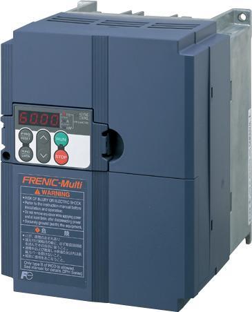
22 Multi-function Keypad
23 NEMA 1 Models:
24 NEMA 1 Models: Type FRNF12E1S-2U + NEMA1-0.2E1S-27 FRNF25E1S-2U + NEMA1-0.2E1S-27 FRNF12E1S-7U + NEMA1-0.2E1S-27 FRNF25E1S-7U + NEMA1-0.2E1S-27 FRNF50E1S-2U + NEMA1-0.4E1S-27 FRNF50E1S-7U + NEMA1-0.4E1S-27 Dimensions W H D 3.27 (83) 6.69 (170) 3.68 (93.5) 4.27 (108.5) FRN001E1S-2U + NEMA1-0.75E1S (133.5) FRN002E1S-2U + NEMA1-2.2E1S-24 FRN003E1S-2U + NEMA1-2.2E1S-24 FRN002E1S-4U + NEMA1-2.2E1S-24 FRN003E1S-4U + NEMA1-2.2E1S-24 FRN005E1S-2U + NEMA1-3.7E1S-24 FRN005E1S-4U + NEMA1-3.7E1S (113) 5.63 (143) 7.15 (181.6) 9.91 (251.8) 5.96 (151.5) 6.00 (152.5) B C FRN003E1S-7U + NEMA1-3.7E1S-24 FRN007E1S-2U + NEMA1-7.5E1S-24 FRN010E1S-2U + NEMA1-7.5E1S-24 FRN007E1S-4U + NEMA1-7.5E1S-24 FRN010E1S-4U + NEMA1-7.5E1S-24 FRN015E1S-2U + NEMA1-15E1S (190.6) (271.2) 6.22 (158) D FRN020E1S-2U + NEMA1-15E1S-24 FRN015E1S-2U + NEMA1-15E1S-24 FRN020E1S-2U + NEMA1-15E1S (220) (315) 7.68 (195) E FRNF50E1S-4U + NEMA1-0.4E1S (127.3) 4.45 (113) 7.09 (180) FRN001E1S-4U + NEMA1-0.75E1S (151.3) FRN001E1S-7U + NEMA1-0.75E1S (83) 6.69 (170) 6.04 (153.5) FRN002E1S-7U + NEMA1-1.5E1S (113) 7.15 (181.6) 6.36 (161.5) B Model A A
General Specifications FECA-TE /2010. Phone: Fax: Web:
 General Specifications FECA-TE-117 06/2010 1. Standard Specifications 1) Three-phase 230V series Output ratings Input ratings Braking Item Specifications Type (FRN C1S-2U) F12 F25 F50 001 002 003 005 Nominal
FRN E1-4LM FRN E1-7LM
 Application Elevator Only Special Specification Described Model FRN E1-2LM a FRN E1-4LM FRN E1-7LM a a Specifications for Description in this specification takes priority over catalogues, operation manuals
AV-300i Specifications. Saftronics Inc. PC10 Product Specifications PC10. Mini Vector AC Drive
 Saftronics Inc. www.saftronics.com TM AV-300i Specifications PC10 Product Specifications PC10 Mini Vector AC Drive 1 (1) T hree-phas e 230V input Drive Hp 1/8 1/4 1/2 1 2 3 5 7.5 10 Nominal applicable
General Specifications
 General Specifications FECA-TE-115 Braking Input ratings for single phase input a) Output ratings for single phase input a) Input ratings for three phase input Output ratings for three phase input Standard
Caution. Three-phase 400V series FRN0.4C1S-4A FRN0.75C1S-4A FRN1.5C1S-4A FRN2.2C1S-4A FRN3.7C1S-4A
 Variation Caution The contents of this catalog are provided to help you select the product model that is best for you. Before actual use, be sure to read the User s Manual thoroughly to assure correct
AV-300i Specifications. Saftronics Inc. VG10 Product Specifications VG10. Dynamic Vector Drive
 Saftronics Inc. www.saftronics.com TM AV-300i Specifications VG10 Product Specifications VG10 Dynamic Vector Drive 1 Category Item Description Nominal Motor 230 VAC, 3 Phase 1/4 Hp to 125 Hp 460 VAC, 3
Series Concepts. Ideal functions to meet various needs. New, compact design. Simple operation. Flexible through optionals
 MEH441a Series Concepts Ideal functions to meet various needs New, compact design Simple operation Flexible through optionals A broad range of model variations Actual size Global products The FRENIC-Mini
QUICK GUIDE PUMP CONTROL. High performance Compact Inverter. Date Version 22/09/
 QUICK GUIDE PUMP CONTROL High performance Compact Inverter Date Version 22/9/29 1..3 Version Details Date Written Checked Approved 1.. Draft J. M. Ibáñez J. Català 1..1 Second Version 17/9/29 J. M. Ibáñez
General Specifications
 General FECATE120 1. Standard 1) 230 V series HD mode designed for heavy duty load applications Item Type (FRN G1S2U) Nominal applied motor *1 for three [HP] Nominal applied motor *1 for single [HP] Output
AF-300 G11 Specifications. GE Industrial Systems. Product Specifications AF-300 G11
 apple GE Industrial Systems Product Specifications AF-300 G11 TM 1 Category Item Description Nominal Motor 230 VAC, 3 Phase 1/4 Hp to 125 Hp 460 VAC, 3 Phase 1/2 Hp to 450 Hp Braking Torque (Standard)
Series Concepts. Ideal functions to meet various needs. New, compact design. Simple operation. Flexible through optionals
 MEH451c Series Concepts Ideal functions to meet various needs New, compact design Simple operation Flexible through optionals A broad range of model variations Actual size Global products The FRENIC-Mini
VFD - D700 Series Specifications. The latest low-cost variable speed control solution for centrifugal pumps.
 VFD - D700 Series Specifications The latest low-cost variable speed control solution for centrifugal pumps. Built-in PID Control to maintain pressure, flow, measured value, and much more 125% overload
CTi Automation - Phone: Fax: Web: -
 CONTENTS Chapter 1 Specifications 1. Standard Specifications... 1-2 1.1 Three-phase 230V FRENIC5000G11S Series... 1-2 1.2 Three-phase 460V FRENIC5000G11S Series... 1-3 1.3 Three-phase 230V FRENIC5000P11S
[ 4 ] Using pulse train input (F01 = 12)
![[ 4 ] Using pulse train input (F01 = 12)](/thumbs/90/102625444.jpg "[ 4 ] Using pulse train input (F01 = 12)") [ 4 ] Using pulse train input (F01 = 12) Selecting the pulse train input format (d59) A pulse train in the format selected by the function code d59 can give a frequency command to the inverter. Three types
[ 4 ] Using pulse train input (F01 = 12) Selecting the pulse train input format (d59) A pulse train in the format selected by the function code d59 can give a frequency command to the inverter. Three types
High Performance AC Drives kW VXM
 VXM 5 year warranty Dual rated from 5.5kW High performance open and closed loop operation Speed or torque control 15 preset speeds FieldBus options Profibus, DeviceNet etc RS485 port IMO loader PC software
FUJI Inverter. Standard Specifications
 FUJI Inverter o Standard Specifications Norminal applied motor The rated output of a general-purpose motor, stated in kw. That is used as a standard motor. Rated capacity The rating of an output capacity,
TOSVERT TM VF-nC3 Parameter List
 TOSVERT TM VF-nC Parameter List E658664 - Setting information * Please fill it in if necessary. Item Content Item Content Setting date / person Customer Application Application model Motor manufacturer
OPC-E1-PG3 Specifications
 OPC-E1-PG3 Specifications Power Electronics Business Group Drive Division Development Dept. b DATE NAME APPROVE a DRAWN 2006-06-05 O. Mizuno CHECKED 2006-06-06 T. Ichihara K. Fujita Fuji Electric Co.,
D SERIES EM16 IP 20 / NEMA 1 & IP 66 / NEMA 4X COMPACT VECTOR CONTROL DRIVE EM 16 COMPACT VECTOR CONTROL DRIVE
 D SERIES EM16 IP 20 / NEMA 1 & IP 66 / NEMA 4X COMPACT VECTOR CONTROL DRIVE EM 16 COMPACT VECTOR CONTROL DRIVE 1 2 SERIES 1 2 pag. 4 pag. 5 Applications Model identification 3 pag. 5 4 pag. 6 Capacity
BOSTON GEAR CONTROLLERS. ACE 20 Series 1/8 through 10 HP Adjustable Frequency AC Motor Controllers. MTY (81)
") BOSTON GEAR CONTROLLERS ACE 20 Series 1/8 through 10 HP Adjustable Frequency AC Motor Controllers ACE 20 Series Offering full-featured control in high torque, low speed applications from 1/8 to 10 HP,
BOSTON GEAR CONTROLLERS ACE 20 Series 1/8 through 10 HP Adjustable Frequency AC Motor Controllers ACE 20 Series Offering full-featured control in high torque, low speed applications from 1/8 to 10 HP,
Series Concepts -'0+ ) 1!!!! $ ( $ $ # $ 2 ( $!! $ #!! $! $ ( $! # # $ $ 2 3 $! 45 (. ( ) / # 6 $( $ * &7 89 : $ ')8;" : - 2 -
 1!!!! $ ( $ $ # $ 2 ( $!! $ #!! $! $ ( $! # # $ $ 2 3 $! 45 (. ( ) / # 6 $( $ * &7 89 : $ ')8; : - 2 -") MEH441c Series Concepts Ideal functions to meet various needs New, compact design Simple operation Flexible through optionals A broad range of model variations Global products Actual size The FRENIC-Mini
MEH441c Series Concepts Ideal functions to meet various needs New, compact design Simple operation Flexible through optionals A broad range of model variations Global products Actual size The FRENIC-Mini
idrive AC variable speed
 idrive AC variable speed General Purpose AC Variable Speed Drives 1Ø, 110V / 50~60Hz, 0.2~0.75kW (¼~1HP)* 1Ø, 230V / 50~60Hz, 0.2~2.2kW (¼~3HP) 3Ø, 230V / 50~60Hz, 0.2~2.2kW (¼~3HP)* 3Ø, 400V / 50~60Hz,
α α Retry count clear Alarm reset Active End of retry S-curve time during accelerati on H04: (Count) setting S curve time during decelerati on
 setting S curve time during decelerati on") Upon success of retry Alarm Occurrence Disappearance Time S-curve acceleration/deceleration To reduce the shock of the mechanical system, the change in the output frequency is made smooth when the frequency
Upon success of retry Alarm Occurrence Disappearance Time S-curve acceleration/deceleration To reduce the shock of the mechanical system, the change in the output frequency is made smooth when the frequency
Fan and Pump AC Inverter
 Fan and Pump AC Inverter Key Features for Fan and Pump Applications PID and Auto Energy Saving Functions. Input Phase Loss and Output Phase Loss Protection. LCD Keypad can be used to copy parameter settings
IMO Jaguar VXG. Quick Start Guide. Refer to VXG Manual for full data. Available to download from IMO Precision Controls Ltd.
 Quick Start Guide Refer to VXG Manual for full data. Available to download from www.imopc.com. IMO Jaguar VXG Thank you for purchasing our Jaguar VXG series of inverters. This product is designed to drive
S11 Adjustable Speed Drive Engineering Specification
 PART 1 - GENERAL 1.0 Scope This specification shall cover Toshiba S11 AC Variable Frequency Drives, 6 pulse for 3- phase 200-240VAC, 380-500VAC and single phase 200V to 240VAC. 1.1 References A. National
Year. Caution. Index. 2 Features. 5/6 Range and Application. 7 Other Features. 8 Specifications. 12 Terminal Functions
 Index Caution 2 Features 5/6 Range and Application 7 Other Features 8 Specifications 2 Terminal Functions This publication is only to be used as a guide. Please seek the full instruction manual before
ROLL TO ROLL FUNCTION MANUAL FR-A (0.4K)-04750(90K)-R2R FR-A (0.4K)-06830(280K)-R2R FR-A (315K)-12120(500K)-R2R
-04750(90K)-R2R FR-A (0.4K)-06830(280K)-R2R FR-A (315K)-12120(500K)-R2R") INVERTER ROLL TO ROLL FUNCTION MANUAL FR-A820-00046(0.4K)-04750(90K)-R2R FR-A840-00023(0.4K)-06830(280K)-R2R FR-A842-07700(315K)-12120(500K)-R2R Roll to Roll Function The FR-A800-R2R inverter has dedicated
INVERTER ROLL TO ROLL FUNCTION MANUAL FR-A820-00046(0.4K)-04750(90K)-R2R FR-A840-00023(0.4K)-06830(280K)-R2R FR-A842-07700(315K)-12120(500K)-R2R Roll to Roll Function The FR-A800-R2R inverter has dedicated
VF-nC1 Adjustable Speed Drive Engineering Specification
 PART 1 - GENERAL 1.0 Scope This specification shall cover Toshiba VF-nC1 AC Variable Frequency Drives, 6 pulse for 100V single-phase 0.1 to 0.75kW, 200V single-phase 0.2 to 2.2kW and 200V threephase 0.1
ADJUSTABLE SPEED DRIVES. AS1 Drive
 ADJUSTABLE SPEED DRIVES AS1 Drive Toshiba s New ASD Product Line The AS1 drive builds on Toshiba s history of supplying powerful, reliable, and versatile drives. We have combined our best drive features
Index 2. G Gain settings 4 31 Glossary of terms A 2 Grommets 2 13
 Index A A Group functions 3 9 AC reactors 5 3 Acceleration 1 15, 3 8 characteristic curves 3 26 second function 3 24 two-stage 4 19 Acceleration stop function 3 21 Access levels 3 5, 3 36, 4 25 Access
CHAPTER AC DRIVE PARAMETERS. In This Chapter...
 CHAPTER AC DRIVE 4 PARAMETERS In This Chapter... GS2 Parameter Summary....................4 2 Detailed Parameter Listings.................4 11 Motor Parameters........................4 11 Ramp Parameters.........................4
GS1 Parameter Summary Detailed Parameter Listings...4 9
 CHAPTER AC DRIVE 4 PARAMETERS Contents of this Chapter... GS1 Parameter Summary...............................4 2 Detailed Parameter Listings..............................4 9 Motor Parameters.........................................4
E3 Adjustable Speed Drive Engineering Specification
 E3 Adjustable Speed Drive Engineering Specification PART 1 - GENERAL 1.0 Scope This specification shall cover Toshiba E3 AC Variable Frequency Drives, 6 pulse for 230V and 460V. 1.1 References A. National
New FUJI ELECTRIC INVERTERS
 High Performance Inverter New FUJI ELECTRIC INVERTERS The FRENIC-Ace Inverters are full feature drives offering great value and maintain high performance through optimal design for a wide range of applications
CHAPTER 8 PARAMETER SUMMARY
 CHAPTER PARAMETER SUMMARY Group 0: System Parameter VFD-V Series 00-00 Identity Code Based on the model type 00-01 Rated Current Display 00-02 Parameter Reset 00-03 00-04 Star-up Display of the Drive Definitions
VFS11 Parameter List for up to CPU version 105
 E65824 VFS Parameter List for up to CPU version 5 Setting Date Customer End user Application Application No/Serial No Inverter s Type-Form Quantity Inverter s Serial No Motor s capacity If user s value
6.9 Jump frequency - Avoiding frequency resonance
 E581595.9 Jump frequency - Avoiding frequency resonance : Jump frequency : Jumping width Function Resonance due to the natural frequency of the mechanical system can be avoided by jumping the resonant
Warning!! 2. The drive contains high voltage that can cause electric shock resulting in personal injury or loss of life.
 ! Warning!! 1. Please read this manual completely before installing the drive. 2. The drive contains high voltage that can cause electric shock resulting in personal injury or loss of life. 3. Be sure
(Supplement to Instruction Manual)
") (Supplement to Instruction Manual) High Performance, Multifunction Inverter About this document This manual, a supplement for the FRENIC-MEGA series of inverters having a ROM version 3600 or later, contains
(Supplement to Instruction Manual) High Performance, Multifunction Inverter About this document This manual, a supplement for the FRENIC-MEGA series of inverters having a ROM version 3600 or later, contains
QUICK GUIDE SINGLE PUMP CONTROL. Frequency inverter for pump control applications SG_PUMP_CONTROL_HVAC_EN_1.1.0
 QUICK GUIDE SINGLE PUMP CONTROL Frequency inverter for pump control applications SG_PUMP_CONTROL_HVAC_EN_1.1.0 Version Details Date Written Checked Approved 1.0.0 Draft version 03/10/13 J. Alonso 1.1.0
Variable Frequency Drive / Inverter (0.4 ~ 280kW)
") Variable Frequency Drive / Inverter (0.4 ~ 280kW) & Standard Features Configuration Comparison Comparison Table Enclosure IP00 IP20 NEMA 1 Rating Single phase 0.4 2.2kW 0.4 1.5kW Three phase 0.4 4kW Constant
Variable Frequency Drive / Inverter (0.4 ~ 280kW) & Standard Features Configuration Comparison Comparison Table Enclosure IP00 IP20 NEMA 1 Rating Single phase 0.4 2.2kW 0.4 1.5kW Three phase 0.4 4kW Constant
New. High Performance Inverter. 24A1-E-0042e4
 High Performance Inverter New F U J I E L E C T R I C I N V E RT E R S The FRENIC-Ace Inverters are full feature drives offering great value and maintain high performance through optimal design for a wide
9. RS485 Communication
 9. RS485 The communication between inverter and external controller is doing by RS485 using modular connector in cling to inverter controller. Function Initial Minimum Maximum code Value Unit Description
ADJUSTABLE SPEED DRIVES FS1
 ADJUSTABLE SPEED DRIVES FS1 Now Available With LonWorks BACnet & MetasysN2 FS1 Model FLA & Dimensions (in.)/ Weight (lbs.) VOLTAGE HP MODEL NUMBER FLA FRAME Dimensions (in.) SHIPPING H W D WEIGHT (lbs.)
New FUJI ELECTRIC INVERTERS
 High Performance Inverter New FUJI ELECTRIC INVERTERS The FRENIC-Ace Inverters are full feature drives offering great value and maintain high performance through optimal design for a wide range of applications
SJ100 Series Inverter Quick Reference Guide. Single-phase Input 200V Class Three-phase Input 200V Class Three-phase Input 400V Class
 HITACHI SJ1 Series Inverter Quick Reference Guide Single-phase Input 2V Class Three-phase Input 2V Class Three-phase Input 4V Class Hitachi Industrial Equipment Systems Co., Ltd. Manual No. NB5821XD Dec.
Manual Overview...1 2
 GETTING STARTED CHAPTER 1 Contents of this Chapter... Manual Overview.....................................1 2 Overview of this Publication..................................1 2 Who Should Read This Manual...............................1
System configuration. Ratings 400 V Class three-phase 90 to 800 kw 690 V Class three-phase 90 to 1000 kw SX-D. Frequency inverters.
 ~ ~ SX High performance Vector Control IP54 full range. Compact design & Robustness Built-in Filter according to C3 Class Built-in Fusses (From 200 kw) Safety according EN13849-1 and EN62061 standards
ADJUSTABLE SPEED DRIVES VF-S11 Sords Electric
 ADJUSTABLE SPEED DRIVES VF-S11 The Next Generation of Micro Inverters is Here. The S11 provides maximum torque with precise speed control. It features an easy-to-use, quiet and compact design. In addition,
9. RS485 Communication (Option)
") 9. RS485 (Option) The communication between inverter and external controller is doing by RS485 using modular connector in cling to inverter controller. Function Initial Minimum Maximum code Value Unit
9. RS485 (Option) The communication between inverter and external controller is doing by RS485 using modular connector in cling to inverter controller. Function Initial Minimum Maximum code Value Unit
TECO F510 Inverter. Quick Start Guide. Step 1. Supply & Motor connection
 Quick Start Guide TECO F510 Inverter This guide is to assist you in installing and running the inverter and verify that it is functioning correctly for it s main and basic features. For detailed information
13. Before making a service call Trip information and remedies
 . Before making a service call Trip information and remedies.1 Trip causes/warnings and remedies When a problem arises, diagnose it in accordance with the following table. If it is found that replacement
D SERIES LM16. COMPACT DRIVE V/f and SLV CONTROL. LM16 COMPACT DRIVE V/f and SLV CONTROL
 D SERIES LM16 COMPACT DRIVE V/f and SLV CONTROL LM16 COMPACT DRIVE V/f and SLV CONTROL 1 2 SERIES 1 2 page 4 page 6 Introduction Fields of application 3 page 7 4 page 8 Designation Product offer 5 6 page
HITACHI. L100-M Series Inverter Quick Reference Guide. Hitachi Industrial Equipment Systems Co., Ltd. Single-phase Input 100V Class
 HITACHI L1-M Series Inverter Quick Reference Guide Single-phase Input 1V Class Hitachi Industrial Equipment Systems Co., Ltd. Manual No. NB5741XD December 23 Caution: Be sure to read the L1 Inverter Manual
FRENIC-Ace Specifications for Global Model [GB]
![FRENIC-Ace Specifications for Global Model [GB]](/thumbs/78/78614258.jpg "FRENIC-Ace Specifications for Global Model [GB]") FRENIC-Ace Specifications for Global Model [GB] FECA-TE-156 1. STANDARD SPECIFICATIONS 1.1. Three phase 230V class series Items Specifications Type (FRN E2S-2GB) 0001 0002 0004 0006 0010 0012 0020 0030
FRENIC-Ace Specifications for Global Model [GB] FECA-TE-156 1. STANDARD SPECIFICATIONS 1.1. Three phase 230V class series Items Specifications Type (FRN E2S-2GB) 0001 0002 0004 0006 0010 0012 0020 0030
The new Yaskawa Varispeed G7 Inverter
 The new Yaskawa Varispeed G7 Inverter Unique new 3-level PWM flux vector Constant or variable torque applications control method 0.4 kw to 300 kw power range Exceptional low speed/high torque control Quick
CHAPTER 8 SUMMARY OF PARAMETER SETTINGS
 CHAPTER 8 SUMMARY OF PARAMETER SETTINGS VFD-S Series!: The parameter can be set during operation, *: Twice the value for 460V class. Group 0 User Parameters Parameters Explanation s 0-00 Identity Code
Frequency Inverters. SJ700B Series. Powerful Inverter for General Purpose Use. SJ700B Series
 Frequency Inverters Frequency Inverters High performance, powerful functions, user friendly. A powerful drive with high starting torque and easy configuration Improved Sensorless Vector Control and Auto
SX (690 V) System configuration
 System configuration") SX (690 V) High performance Vector Control IP54 full range Compact design & Robustness Built-in Filter according to C3 Class Built-in Fuses (From 200 kw) Safety according EN13849-1 and EN62061 standards
SX (690 V) High performance Vector Control IP54 full range Compact design & Robustness Built-in Filter according to C3 Class Built-in Fuses (From 200 kw) Safety according EN13849-1 and EN62061 standards
vacon nx all in one application manual ac drives Phone: Fax: Web: -
 vacon nx ac drives all in one application manual vacon 1 INDEX Document ID:DPD00903A Revision release date: 30.3.2012 1. Basic Application...5 1.1. Introduction...5 1.1.1. Motor protection functions in
NX series Constant and variable torque Variable Speed Drives for induction motors
 Honeywell All in One Application Manual NX series Constant and variable torque Variable Speed Drives for induction motors Subject to changes without notice CONTENTS NX "All in One" APPLICATION MANUAL INDEX
AF91 Adjustable Frequency Drives Series B
 Effective: January, 00 Page New Information AF9 Adjustable Model AF9 Description Model AF9 Adjustable Frequency AC Drives are designed to provide adjustable speed control of -phase motors. These microprocessor-based
INDEX. i 1. B Braking Resistor Dimensions: A 24 Braking Resistors: A 20 Braking Units: A 20. DURAPULSE AC Drive User Manual
 INDEX A AC Drive Cover: 1 6 Dimensions: 2 4 External Parts and Labels: 1 6 Heat Sink Fins: 1 6 Input Mode Switch (Sink/Source): 1 6 Introduction to DuraPulse GS3 AC drive: 1 3 Keypad: 1 6 Model Number
SX (400 V) System configuration
 System configuration") ~ ~ SX (400 V) High performance Vector Control IP54 full range. Compact design & Robustness Built-in Filter according to C3 Class Built-in Fuses (From 200 kw) Safety according EN13849-1 and EN62061 standards
~ ~ SX (400 V) High performance Vector Control IP54 full range. Compact design & Robustness Built-in Filter according to C3 Class Built-in Fuses (From 200 kw) Safety according EN13849-1 and EN62061 standards
SX (400V) System configuration
 System configuration") ~ ~ SX (400V) High performance Vector Control IP54 full range. Compact design & Robustness Built-in Filter according to C3 Class Built-in Fusses (From 200 kw) Safety according EN13849-1 and EN62061 standards
~ ~ SX (400V) High performance Vector Control IP54 full range. Compact design & Robustness Built-in Filter according to C3 Class Built-in Fusses (From 200 kw) Safety according EN13849-1 and EN62061 standards
This operation manual is intended for users with basic knowledge of electricity and electric devices.
 This operation manual is intended for users with basic knowledge of electricity and electric devices. Safety Information Safety Information Read and follow all safety instructions in this manual precisely
ATV12H018F1 variable speed drive ATV kW hp V - 1ph
 Characteristics variable speed drive ATV12-0.18kW - 0.25hp - 100..120V - 1ph Main Range of product Altivar 12 Product or component type Product destination Product specific application Assembly style Component
ATV12H037F1 variable speed drive ATV kW hp V - 1ph - with heat sink
 Characteristics variable speed drive ATV12-0.37kW - 0.55hp - 100..120V - 1ph - with heat sink Main Range of product Altivar 12 Product or component type Product destination Product specific application
SAFETY INSTRUCTIONS WARNING
 Important User Information Thank you for purchasing LS Variable Frequency Drives! SAFETY INSTRUCTIONS Always follow safety instructions to prevent accidents and potential hazards from occurring. In this
Operating Instructions
 4XH35QB151210 Small General Frequency Converter Operating Instructions 220V 0.75KW 5.5KW 400V 0.75KW 15KW Please read the instruction carefully and understand the contents so that it can be installed and
Compact & Powerful Inverter STARVERT ig5a 0.4~1.5kW 1phase 200~230Volts 0.4~22kW 3Phase 200~230Volts 0.4~22kW 3Phase 380~480Volts
 Compact & Powerful Inverter STARVERT ig5a 0.4~1.5kW 1phase 200~230Volts 0.4~22kW 3Phase 200~230Volts 0.4~22kW 3Phase 380~480Volts Inverter STARVERT ig5a LS Starvert ig5a is very competitive in its price
Rexroth Frequency Converter Fe 0.75 kw to 7.5 kw / 400 VAC
 Electric Drives and Controls Hydraulics Linear Motion and Assembly Technologies Pneumatics Rexroth Frequency Converter Fe 0.75 kw to 7.5 kw / 400 VAC Simple, scalable and economical Service Bosch Rexroth
SYSDRIVE 3G3XV Inverter 3G3XV- -EV2 Operation Manual
 SYSDRIVE 3G3XV Inverter 3G3XV- -EV2 Operation Manual Revised November 1997 iv Notice: OMRON products are manufactured for use according to proper procedures by a qualified operator and only for the purposes
ATV12HU22M2. Main. Range of product Altivar 12. Component name Quantity per set Set of 1. Built-in fan. Motor power hp Communication port protocol
 Product datasheet Characteristics ATV12HU22M2 Complementary Main Range of product Altivar 12 Product or component type Product destination Product specific application Assembly style Component name Variable
LG Variable Frequency Drive
 LG Variable Frequency Drive ig5 Series 0.5-5.4HP (200/400V) Installation, Operation and Maintenance Instruction Read this manual carefully before installing, wiring, operating, servicing or inspecting
ATV12HU40M3 variable speed drive ATV12-4kW - 5hp V - 3ph - with heat sink
 Characteristics variable speed drive ATV12-4kW - 5hp - 200..240V - 3ph - with heat sink Main Range of product Altivar 12 Product or component type Product destination Product specific application Assembly
P-SERIES VFD 1-40HP (200~230VAC), 1-400HP (380~480VAC),3Ø Dual Rated for Constant & Variable Torque Integrated PID Control
, 1-400HP (380~480VAC),3Ø Dual Rated for Constant & Variable Torque Integrated PID Control") P-SERIES VFD 1-40HP (200~230VAC), 1-400HP (380~480VAC),3Ø Dual Rated for Constant & Variable Torque Integrated PID Control NEW FIRMWARE MAKES SETUP A SNAP Application based commissioning allows parameters
P-SERIES VFD 1-40HP (200~230VAC), 1-400HP (380~480VAC),3Ø Dual Rated for Constant & Variable Torque Integrated PID Control NEW FIRMWARE MAKES SETUP A SNAP Application based commissioning allows parameters
SJ700 series High performance with Many useful Functions and, yet User Friendly. WJ200 series Pursuing the Ideal Compact Inverter NEW
 WJ200 series Pursuing the Ideal Compact Inverter NEW SJ700 series High performance with Many useful Functions and, yet User Friendly X200 series Simple, Trip-suppression and Eco-friendly Compact Inverter
ATV12H037F1 variable speed drive ATV kW hp V - 1ph - with heat sink
 Characteristics variable speed drive ATV12-0.37kW - 0.55hp - 100..120V - 1ph - with heat sink Product availability : Stock - Normally stocked in distribution facility Price* : 191.76 USD Main Range of
ADVANCED AND EVER ADVANCING FR-V200. FR-V200 series
 ADVANCED AND EVER ADVANCING FR-V200 FR-V200 series CONTENTS 1 SPECIFICATIONS 1 1.1 OPERATION PRINCIPLE...1 1.1.1 What is vector control?...1 1.2 Instructions for Using the Inverter...3 1.3 Specification
TAC ATV38, IP55. Variable Speed Drives for Asynchronous Motors. 3-phase. 380/460 V, Hz
 TAC ATV8, IP55 Variable Speed Drives for Asynchronous Motors. -phase. 80/460 V, 50-60 Hz E-60-24 24 May 2004 ATV 8 IP55 drives are specifically designed for pump and fan applications powered by a three-phase
VFS9 Parameter List for Version110 or later
 VFS9 Parameter List for Version110 or later Setting Date Customer End user Application Application /Serial Inverter s Type-Form Quantity Inverter s Serial Motor s capacity If user s value is same as shipping
MD310 Quick Start Manual. General-Purpose AC Drive
 MD310 Quick Start Manual General-Purpose AC Drive ersion 0.1 Dated 14 th OCT, 2013 CONTENTS CHAPTER 1 PRODUCT INFORMATION... 1 1.1 Designation... 1 1.2 Nameplate... 1 1.3 General Specifications... 2 CHAPTER
Ambient Conditions Storage Conditions Installation Minimum Clearances and Air Flow...2 3
 CHAPTER INSTALLATION 2 AND WIRING Contents of this Chapter... Ambient Conditions..............................2 2 Storage Conditions...............................2 2 Installation.....................................2
STARTING GUIDE FRENIC MEGA. High Performance Multifunction Inverter. 3 ph 400 V 0.4 to 75 kw 3 ph 200 V 0.4 to 55 kw SG_MEGA_GB_1.
 STARTING GUIDE FRENIC MEGA High Performance Multifunction Inverter 3 ph 400 V 0.4 to 75 kw 3 ph 200 V 0.4 to 55 kw SG_MEGA_GB_1.0 Index Version Date Applied by 0.4.0 Version for proofreading 16.11.07 Andreas
NXL HVAC APPLICATION MANUAL Programming manual for NXL HVAC drives
 NXL HVAC APPLICATION MANUAL Programming manual for NXL HVAC drives Page 2 (68) Index Honeywell HVAC Application (Software [ALFIQ105] Ver.2.09) INDEX 1. INTRODUCTION... 3 2. CONTROL I/O... 3. HVAC APPLICATION
USER S MANUAL. Customised to your machine Model: RX 200 V Class Three-Phase Input 0.4 to 55 kw 400 V Class Three-Phase Input 0.
 Cat. No. I560-E2-03A-X RX Customised to your machine Model: RX 200 V Class Three-Phase Input 0. to 55 kw 00 V Class Three-Phase Input 0. to 132 kw USER S MANUAL Introduction Introduction Thank you for
INTERNATIONAL SERVICE BULLETIN - I #2-319 Liberty - Delta M+ VFD parameter list. A VFD parameter list is required when replacing a DELTA M+ VFD.
 RYKO Manufacturing Company 116 N.W. 54th Ave. P.O.Box 38 Grimes, Iowa 5111 Phone (515) 986-37 www.ryko.com Fax (515) 986-3621 sales@ ryko.com INTERNATIONAL SERVICE BULLETIN - I #2-319 Liberty - Delta M+
SYSDRIVE 3G3HV Inverter Models The following 200- and 400-V class 3G3HV Inverter models are available.
 Function The 3G3HV High-capacity General-purpose Inverter is an easy-to-use inverter that has advanced features, such as PID control and energy-saving operations. SYSDRIVE 3G3HV Inverter Models The following
Brake resistor can be connected. 150%/1Hz high starting torque by General -purpose magnetic flux vector control. Safety stop function
 Features 1 Highly reliable inverter! Compact yet equipped with highest level of function/performance!! Standard specifications 5 Safety stop function (1) (1) The FR-D700 series is compliant to the EU Machinery
Multi-function, Compact Inverters. 3G3MV Series
 Multi-function, Compact Inverters 3G3MV Series There has been a great demand for inverters with more functions and easier motor control than conventional i OMRON's powerful, compact 3G3MV Series with versat
Inverter Drive /Vector Drive Motors & Controls
 H2 Inverter/ Encoderless Vector Inverter Drive /Vector Drive & Controls 3/4 thru 50 180-264 VAC 3 Phase - 50/60 Hz 3/4 thru 60 340-528 VAC 3 Phase - 50/60 Hz 3/4 thru 60 515-660 VAC 3 Phase - 60 Hz HVAC
ADTECH Solar inverter
 ADTECH Solar inverter 1. Product description Thank you very much for your selection of special solar inverter launched by ADTECH (SHENZHEN) TECHNOLOGY CO., LTD. Solar energy special inverter is designed
ig5a Compact AC Drive 0.4~1.5kW(0.5~2HP) 1-phase 200~230Volts 0.4~22kW(0.5~30HP) 3-Phase 200~230Volts 0.4~22kW(0.5~30HP) 3-Phase 380~480Volts
 1-phase 200~230Volts 0.4~22kW(0.5~30HP) 3-Phase 200~230Volts 0.4~22kW(0.5~30HP) 3-Phase 380~480Volts") iga Compact AC Drive ~1.kW(0.~2HP) 1-phase 200~230Volts ~22kW(0.~30HP) 3-Phase 200~230Volts ~22kW(0.~30HP) 3-Phase 380~480Volts Drive STARVERT iga LS Starvert iga is very competitive in its price and shows
iga Compact AC Drive ~1.kW(0.~2HP) 1-phase 200~230Volts ~22kW(0.~30HP) 3-Phase 200~230Volts ~22kW(0.~30HP) 3-Phase 380~480Volts Drive STARVERT iga LS Starvert iga is very competitive in its price and shows
INSTRUCTION MANUAL FVR-E11S-7EN
 INSTRUCTION MANUAL FVR-E11S-7EN Three-phase 400V input FVR-E11S-4EN Single-phase 200V input Low noise high performance inverter Caution Thank you for purchasing our FVR-E11S series inverter. This product
GMD Series. Three-phase 200 V series: GMD to 00150L Three-phase 400 V series: GMD to 00150H Single-phase 200 V series: GMD to 00220S
 GMTCNT Instruction Manual Compact Inverter GMD Series Three-phase 200 V series: GMD-00040 to 00150L Three-phase 400 V series: GMD-00040 to 00150H Single-phase 200 V series: GMD-00040 to 00220S Thank you
GE Consumer & Industrial AF-300 G11. User s Guide
 GE Consumer & Industrial AF-300 G11 User s Guide 2007 by GE Drives, Inc. All rights reserved. These instructions do not purport to cover all details or variations in equipment, nor to provide every possible
Version number A=standard P=Cold Plate (Frame A only) T=Brake chopper (Frame A only) Input voltage 11=115VAC 21=230VAC 1φ 23=230VAC 3φ 43=400VAC
 T=Brake chopper (Frame A only) Input voltage 11=115VAC 21=230VAC 1φ 23=230VAC 3φ 43=400VAC") Type number key VFD 007 E 43 A Version number A=standard P=Cold Plate (Frame A only) T= (Frame A only) Input voltage 11=115VAC 21=230VAC 1φ 23=230VAC 3φ 43=400VAC VFD-E series Power 007=0.75kW 022=2.2kW
Type number key VFD 007 E 43 A Version number A=standard P=Cold Plate (Frame A only) T= (Frame A only) Input voltage 11=115VAC 21=230VAC 1φ 23=230VAC 3φ 43=400VAC VFD-E series Power 007=0.75kW 022=2.2kW
ig5a 0.4~1.5kW (0.5~2HP) 1phase 200~230Volts 0.4~22kW (0.5~30HP) 3Phase 200~230Volts 0.4~22kW (0.5~30HP) 3Phase 380~480Volts Compact & Powerful Drive
 1phase 200~230Volts 0.4~22kW (0.5~30HP) 3Phase 200~230Volts 0.4~22kW (0.5~30HP) 3Phase 380~480Volts Compact & Powerful Drive") Compact & Powerful Drive iga ~1.kW (0.~2HP) 1phase 200~230Volts ~22kW (0.~30HP) 3Phase 200~230Volts ~22kW (0.~30HP) 3Phase 380~480Volts Drive Starvert iga LS Starvert iga is very competitive in its price
Compact & Powerful Drive iga ~1.kW (0.~2HP) 1phase 200~230Volts ~22kW (0.~30HP) 3Phase 200~230Volts ~22kW (0.~30HP) 3Phase 380~480Volts Drive Starvert iga LS Starvert iga is very competitive in its price