By: Dr. Ahmed ElShafee
|
|
|
- Frank Rose
- 5 years ago
- Views:
Transcription
,")


 on the y axis to the cutoff")

, not")
1 Lecture (02) Transistor operating point & DC Load line (2), Transistor Bias Circuit 1 By: Dr. Ahmed ElShafee ١ DC Load Line The dc operation can be described graphically using a dc load line. This is a straight line drawn on the characteristic curves from the saturation value where I C =I C(sat) on the y axis to the cutoff value where VCE = VCC on of a transistor circuit on the x axis, The load line is determined by the external circuit (VCC and RC), not the transistor itself, ٢
. ٣ The point at which the load line intersects a characteristic curve represents the Q point for that particular value of IB.")
2 This is the equation of a straight line with a slope of 1/R C, an x intercept of VCE = VCC, and a y intercept of VCC/RC, which is IC(sat). ٣ The point at which the load line intersects a characteristic curve represents the Q point for that particular value of IB. ٤
3 Linear Operation The region along the load line including all points between saturation and cutoff is generally known as the linear region of the transistor s operation. As long as the transistor is operated in this region, the output voltage is ideally a linear reproduction of the input. ٥ AC quantities are indicated by lowercase italic subscripts Assume a sinusoidal voltage, Vin, is superimposed on VBB, I b to vary sinusoidally 100uA above and below its Q point value of 300uA causes the collector current to vary 10 ma above and below its Q point value of 30 ma V ce voltage varies 2.2 V above and below its Q point value of ٦ 3.4 V


4 ٧ Waveform Distortion under certain input signal conditions the location of the Q point on the load line can cause one peak of the Vce waveform to be limited or clipped, When the positive peak is limited, the transistor is being driven into cutoff. ٨
5 input signal is too large for the Q point location and is driving the transistor into cutoff or saturation during a portion of the input cycle. When the negative peak is limited, the transistor is being driven into saturation ٩ When both peaks are limited, the transistor is being driven into both saturation and cutoff by an excessively large input signal. ١٠

6 Example 1 ١١ Solution 1 ١٢
7 ١٣ that before saturation is reached, IC can increase an amount ideally equal to IC can decrease by 39.6 ma before cutoff (I C = 0) is reached the limiting excursion is 21 ma because the Q point is closer to saturation than to cutoff ١٤
8 The 21 ma is the maximum peak variation of the collector current. Actually, it would be slightly less in practice because VCE(sat) is not quite zero. ١٥ Determine the maximum peak variation of the I b base current as follows ١٦

9 Voltage divider bias biasing a transistor for linear operation using a single source resistive voltage divider. A more practical bias method is to use VCC as the single bias source, A dc bias voltage at the base of the transistor can be developed by a resistive voltage divider that consists of R1 and R2, voltage divider bias circuits are designed so that the base current I B is much smaller than the current (I2) through R2 ١٧ Calculate the voltage on the base using the unloaded voltage divider rule you can find the voltages and currents in the circuit ١٨


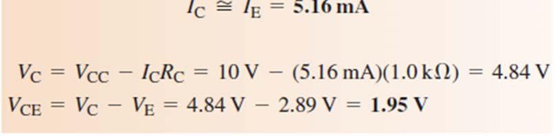
10 Example 02 ١٩ Solution 2 ٢٠

 is at least ten times larger than R2, the loading effect will be 10% or less and the voltage divider is stiff.")
11 Loading Effects of Voltage Divider Bias; DC Input Resistance at the Transistor Base The dc input resistance of the transistor is proportional to β DC when operating in its linear region, the emitter current I E = I B x β DC When the emitter resistor is viewed from the base circuit, the resistor appears to be larger than its actual value because of the dc current gain in the transistor. ٢١ estimate the loading effect by comparing RIN(BASE) to the resistor R2 in the voltage divider. As long as RIN(BASE) is at least ten times larger than R2, the loading effect will be 10% or less and the voltage divider is stiff. If RIN(BASE) is less than ten times R2, it should be combined in parallel with R2. ٢٢

12 Example 3 ٢٣ Solution 3 ٢٤
13 Thanks,.. See you next week (ISA), ٢٥
Lecture (01) Transistor operating point & DC Load line
 Transistor operating point & DC Load line") Lecture (01) Transistor operating point & DC Load line By: Dr. Ahmed ElShafee ١ BJT Characteristic Collector Characteristic Curves B C E ٢ BJT modes of operation Conditions in Cutoff Conditions in Saturation
Lecture (01) Transistor operating point & DC Load line By: Dr. Ahmed ElShafee ١ BJT Characteristic Collector Characteristic Curves B C E ٢ BJT modes of operation Conditions in Cutoff Conditions in Saturation
DC Bias. Graphical Analysis. Script
 Course: B.Sc. Applied Physical Science (Computer Science) Year & Sem.: Ist Year, Sem - IInd Subject: Electronics Paper No.: V Paper Title: Analog Circuits Lecture No.: 3 Lecture Title: Analog Circuits
Figure1: Basic BJT construction.
 Chapter 4: Bipolar Junction Transistors (BJTs) Bipolar Junction Transistor (BJT) Structure The BJT is constructed with three doped semiconductor regions separated by two pn junctions, as in Figure 1(a).
Chapter 5 Transistor Bias Circuits
 Chapter 5 Transistor Bias Circuits Objectives Discuss the concept of dc biasing of a transistor for linear operation Analyze voltage-divider bias, base bias, and collector-feedback bias circuits. Basic
Lecture (09) Bipolar Junction Transistor 3
 Bipolar Junction Transistor 3") Lecture (09) Bipolar Junction Transistor 3 By: Dr. Ahmed ElShafee ١ I THE BJT AS AN AMPLIFIER Amplification is the process of linearly increasing the amplitude of an electrical signal and is one of the
Lecture (09) Bipolar Junction Transistor 3 By: Dr. Ahmed ElShafee ١ I THE BJT AS AN AMPLIFIER Amplification is the process of linearly increasing the amplitude of an electrical signal and is one of the
When you have completed this exercise, you will be able to determine the ac operating characteristics of
 When you have completed this exercise, you will be able to determine the ac operating characteristics of multimeter and an oscilloscope. A sine wave generator connected between the transistor and ground
By: Dr. Ahmed ElShafee
 Lecture (04) Transistor Bias Circuit 3 BJT Amplifiers 1 By: Dr. Ahmed ElShafee ١ Emitter Feedback Bias If an emitter resistor is added to the base bias circuit in Figure, the result is emitter feedback
ECE 334: Electronic Circuits Lecture 2: BJT Large Signal Model
 Faculty of Engineering ECE 334: Electronic Circuits Lecture 2: BJT Large Signal Model Agenda I & V Notations BJT Devices & Symbols BJT Large Signal Model 2 I, V Notations (1) It is critical to understand
The Common Emitter Amplifier Circuit
 The Common Emitter Amplifier Circuit In the Bipolar Transistor tutorial, we saw that the most common circuit configuration for an NPN transistor is that of the Common Emitter Amplifier circuit and that
Lecture (04) BJT Amplifiers 1
 BJT Amplifiers 1") Lecture (04) BJT Amplifiers 1 By: Dr. Ahmed ElShafee ١ The Linear Amplifier A linear amplifier provides amplification of a signal without any distortion so that the output signal A voltage divider biased
Lecture (04) BJT Amplifiers 1 By: Dr. Ahmed ElShafee ١ The Linear Amplifier A linear amplifier provides amplification of a signal without any distortion so that the output signal A voltage divider biased
DEPARTMENT OF ELECTRONICS AND COMMUNICATION ENGINEERING III SEMESTER EC 6304 ELECTRONIC CIRCUITS I. (Regulations 2013)
") DEPARTMENT OF ELECTRONICS AND COMMUNICATION ENGINEERING III SEMESTER EC 6304 ELECTRONIC CIRCUITS I (Regulations 2013 UNIT-1 Part A 1. What is a Q-point? [N/D 16] The operating point also known as quiescent
DEPARTMENT OF ELECTRONICS AND COMMUNICATION ENGINEERING III SEMESTER EC 6304 ELECTRONIC CIRCUITS I (Regulations 2013 UNIT-1 Part A 1. What is a Q-point? [N/D 16] The operating point also known as quiescent
REVIEW TRANSISTOR BIAS CIRCUIT
 EVIEW TANSISTO BIAS CICUIT OBJECTIVES Discuss the concept of dc biasing of a transistor for linear operation Analyze voltage-divider bias, base bias, and collectorfeedback bias circuits. Basic troubleshooting
Bipolar Junction Transistors
 Bipolar Junction Transistors Invented in 1948 at Bell Telephone laboratories Bipolar junction transistor (BJT) - one of the major three terminal devices Three terminal devices more useful than two terminal
Early Effect & BJT Biasing
 Early Effect & BJT Biasing Early Effect DC BJT Behavior DC Biasing the BJT 1 ESE319 Introduction to Microelectronics Early Effect Saturation region Forward-Active region 4 3 Ideal NPN BJT Transfer V Characteristic
Chapter Two "Bipolar Transistor Circuits"
 Chapter Two "Bipolar Transistor Circuits" 1.TRANSISTOR CONSTRUCTION:- The transistor is a three-layer semiconductor device consisting of either two n- and one p-type layers of material or two p- and one
PHY405F 2009 EXPERIMENT 6 SIMPLE TRANSISTOR CIRCUITS
 PHY405F 2009 EXPERIMENT 6 SIMPLE TRANSISTOR CIRCUITS Due Date (NOTE CHANGE): Thursday, Nov 12 th @ 5 pm; Late penalty in effect! Most active electronic devices are based on the transistor as the fundamental
Lecture (08) Bipolar Junction Transistor (2)
 Bipolar Junction Transistor (2)") Lecture (08) ipolar Junction Transistor (2) y: Dr. Ahmed lshafee 1 JT haracteristic ollector haracteristic urves 2 Applying fixed V, increasing V Saturation Assume that V is set to produce a certain value
Lecture (08) ipolar Junction Transistor (2) y: Dr. Ahmed lshafee 1 JT haracteristic ollector haracteristic urves 2 Applying fixed V, increasing V Saturation Assume that V is set to produce a certain value
The collector terminal is common to the input and output signals and is connected to the dc power supply. Common Collector Circuit
 Common Collector Circuit When you have completed this exercise, you will be able to determine the dc operating conditions of a common collector (CC) transistor circuit by using a typical CC circuit. You
I C I E =I B = I C 1 V BE 0.7 V
 Guide to NPN Amplifier Analysis Jason Woytowich 1. Transistor characteristics A BJT has three operating modes cutoff, active, and saturation. For applications, like amplifiers, where linear characteristics
Lab 3: BJT Digital Switch
 Lab 3: BJT Digital Switch Objectives The purpose of this lab is to acquaint you with the basic operation of bipolar junction transistor (BJT) and to demonstrate its functionality in digital switching circuits.
After the initial bend, the curves approximate a straight line. The slope or gradient of each line represents the output impedance, for a particular
 BJT Biasing A bipolar junction transistor, (BJT) is very versatile. It can be used in many ways, as an amplifier, a switch or an oscillator and many other uses too. Before an input signal is applied its
Chapter 6. BJT Amplifiers
 Basic Electronic Devices and Circuits EE 111 Electrical Engineering Majmaah University 2 nd Semester 1432/1433 H Chapter 6 BJT Amplifiers 1 Introduction The things you learned about biasing a transistor
Electronic Circuits II Laboratory 01 Voltage Divider Bias
 Electronic Circuits II Laboratory 01 Voltage Divider Bias # Student ID Student Name Grade (10) 1 Instructor signature 2 3 4 5 Delivery Date -1 / 8 - Objective The objective of this exercise is to examine
7. Bipolar Junction Transistor
 41 7. Bipolar Junction Transistor 7.1. Objectives - To experimentally examine the principles of operation of bipolar junction transistor (BJT); - To measure basic characteristics of n-p-n silicon transistor
Electronic Devices, 9th edition Thomas L. Floyd. Input signal. R 1 and R 2 are selected to establish V B. If the V CE
 3/9/011 lectronic Devices Ninth dition Floyd hapter 5: Transistor ias ircuits The D Operating Point ias establishes the operating point (Q-point) of a transistor amplifier; the ac signal (ma) moves above
Lab 4. Transistor as an amplifier, part 2
 Lab 4 Transistor as an amplifier, part 2 INTRODUCTION We continue the bi-polar transistor experiments begun in the preceding experiment. In the common emitter amplifier experiment, you will learn techniques
Project (02) Dc 2 AC Inverter
 Dc 2 AC Inverter") Project (02) Dc 2 AC Inverter By: Dr. Ahmed ElShafee 1 12v DC to 220v AC Converter Circuit Using Astable Multivibrator Inverter circuits can either use thyristors as switching devices or transistors. Normally
Project (02) Dc 2 AC Inverter By: Dr. Ahmed ElShafee 1 12v DC to 220v AC Converter Circuit Using Astable Multivibrator Inverter circuits can either use thyristors as switching devices or transistors. Normally
Electronic Circuits - Tutorial 07 BJT transistor 1
 Electronic Circuits - Tutorial 07 BJT transistor 1-1 / 20 - T & F # Question 1 A bipolar junction transistor has three terminals. T 2 For operation in the linear or active region, the base-emitter junction
Experiment No. 6 Output Characteristic of Transistor
 Experiment No. 6 Output Characteristic of Transistor Object: To examine the output characteristic of transistor. Apparatus: 1. Two DC power supply. 2. Three AVOmeters. 3. Transistor 2N2222, Resistor 1
UNIT 4 BIASING AND STABILIZATION
 UNIT 4 BIASING AND STABILIZATION TRANSISTOR BIASING: To operate the transistor in the desired region, we have to apply external dec voltages of correct polarity and magnitude to the two junctions of the
Lecture (10) Power Amplifiers (2)
 Power Amplifiers (2)") Lecture (10) Power Amplifiers (2) By: Dr. Ahmed ElShafee ١ Class B/AB Power the ideal maximum peak output current for both dual supply and single supply push pull amplifiers is approximately Ic(sat), and
Lecture (10) Power Amplifiers (2) By: Dr. Ahmed ElShafee ١ Class B/AB Power the ideal maximum peak output current for both dual supply and single supply push pull amplifiers is approximately Ic(sat), and
Electronic Circuits EE359A
 Electronic Circuits EE359A Bruce McNair B206 bmcnair@stevens.edu 201-216-5549 Lecture 4 0 Bipolar Junction Transistors (BJT) Small Signal Analysis Graphical Analysis / Biasing Amplifier, Switch and Logic
E84 Lab 3: Transistor
 E84 Lab 3: Transistor Cherie Ho and Siyi Hu April 18, 2016 Transistor Testing 1. Take screenshots of both the input and output characteristic plots observed on the semiconductor curve tracer with the following
Chapter 12 Power Amplifier
 Chapter 12 Power Amplifier Definitions In small-signal amplifiers the main factors are: Amplification Linearity Gain Since large-signal, or power, amplifiers handle relatively large voltage signals and
BJT as an Amplifier and Its Biasing
 Microelectronic ircuits BJT as an Amplifier and Its Biasing Slide 1 Transfer haracteristics & Biasing Slide 2 BJT urrent-oltage relationship The collector current i I i i B s e i B vbe Is e T v BE T Emitter
UNIT I - TRANSISTOR BIAS STABILITY
 UNIT I - TRANSISTOR BIAS STABILITY OBJECTIVE On the completion of this unit the student will understand NEED OF BIASING CONCEPTS OF LOAD LINE Q-POINT AND ITS STABILIZATION AND COMPENSATION DIFFERENT TYPES
Emitter base bias. Collector base bias Active Forward Reverse Saturation forward Forward Cut off Reverse Reverse Inverse Reverse Forward
 SEMICONDUCTOR PHYSICS-2 [Transistor, constructional characteristics, biasing of transistors, transistor configuration, transistor as an amplifier, transistor as a switch, transistor as an oscillator] Transistor
Chapter Three " BJT Small-Signal Analysis "
 Chapter Three " BJT Small-Signal Analysis " We now begin to examine the small-signal ac response of the BJT amplifier by reviewing the models most frequently used to represent the transistor in the sinusoidal
ITT Technical Institute. ET215 Devices 1. Unit 6 Chapter 3, Sections
 ITT Technical Institute ET215 Devices 1 Unit 6 Chapter 3, Sections 3.7-3.9 Chapter 3 Section 3.7 The Bipolar Transistor as a Switch Objectives: Explain how a transistor can be used as a switch 1. Compute
Video Course on Electronics Prof. D. C. Dube Department of Physics Indian Institute of Technology, Delhi
 Video Course on Electronics Prof. D. C. Dube Department of Physics Indian Institute of Technology, Delhi Module No. # 02 Transistors Lecture No. # 09 Biasing a Transistor (Contd) We continue our discussion
The George Washington University School of Engineering and Applied Science Department of Electrical and Computer Engineering ECE 20 - LAB
 The George Washington University School of Engineering and Applied Science Department of Electrical and Computer Engineering ECE 20 - LAB Experiment # 6 (Part I) Bipolar Junction Transistors Common Emitter
Lecture (06) Bipolar Junction Transistor
 Bipolar Junction Transistor") Lecture (06) Bipolar Junction Transistor By: Dr. Ahmed lshafee ١ Agenda BJT structure BJT operation BJT characteristics ٢ BJT structure The BJT is constructed with three doped semiconductor regions One
Lecture (06) Bipolar Junction Transistor By: Dr. Ahmed lshafee ١ Agenda BJT structure BJT operation BJT characteristics ٢ BJT structure The BJT is constructed with three doped semiconductor regions One
Transistor Biasing. DC Biasing of BJT. Transistor Biasing. Transistor Biasing 11/23/2018
 Transistor Biasing DC Biasing of BJT Satish Chandra Assistant Professor Department of Physics P P N College, Kanpur www.satish0402.weebly.com A transistors steady state of operation depends a great deal
Analog Electronics. Electronic Devices, 9th edition Thomas L. Floyd Pearson Education. Upper Saddle River, NJ, All rights reserved.
 Analog Electronics BJT Structure The BJT has three regions called the emitter, base, and collector. Between the regions are junctions as indicated. The base is a thin lightly doped region compared to the
TRANSISTOR AS SWITCH
 Exp. No #3 TRANSISTOR AS SWITCH Date: OBJECTIVE The purpose of the experiment is to design and analyze the operation of transistor as switch. Also, to design a suitable driver circuit for a given load
Lecture (06) BJT Amplifiers 3
 BJT Amplifiers 3") Lecture (06) BJT Amplifiers 3 By: Dr. Ahmed ElShafee 1 Current Gain 2 Power Gain The overall power gain is the product of the overall voltage gain (Av ) and the overall current gain (Ai). 3 THE COMMON
Lecture (06) BJT Amplifiers 3 By: Dr. Ahmed ElShafee 1 Current Gain 2 Power Gain The overall power gain is the product of the overall voltage gain (Av ) and the overall current gain (Ai). 3 THE COMMON
Lecture (05) BJT Amplifiers 2
 BJT Amplifiers 2") Lecture (05) BJT Amplifiers 2 By: Dr. Ahmed ElShafee 1 Effect of the Emitter Bypass Capacitor on Voltage Gain The emitter bypass capacitor, provides an effective short to the ac signal around the emitter
Lecture (05) BJT Amplifiers 2 By: Dr. Ahmed ElShafee 1 Effect of the Emitter Bypass Capacitor on Voltage Gain The emitter bypass capacitor, provides an effective short to the ac signal around the emitter
UNIT-1 Bipolar Junction Transistors. Text Book:, Microelectronic Circuits 6 ed., by Sedra and Smith, Oxford Press
 UNIT-1 Bipolar Junction Transistors Text Book:, Microelectronic Circuits 6 ed., by Sedra and Smith, Oxford Press Figure 6.1 A simplified structure of the npn transistor. Microelectronic Circuits, Sixth
Small signal Amplifier stages. Figure 5.2 Classification of power amplifiers
 5.1 Introduction When the power requirement to drive the load is in terms of several Watts rather than mili-watts the power amplifiers are used. Power amplifiers form the last stage of multistage amplifiers.
Transistors and Applications
 Chapter 17 Transistors and Applications DC Operation of Bipolar Junction Transistors (BJTs) The bipolar junction transistor (BJT) is constructed with three doped semiconductor regions separated by two
Multivibrators. Department of Electrical & Electronics Engineering, Amrita School of Engineering
 Multivibrators Multivibrators Multivibrator is an electronic circuit that generates square, rectangular, pulse waveforms. Also called as nonlinear oscillators or function generators. Multivibrator is basically
Experiment 8&9 BJT AMPLIFIER
 Experiment 8&9 BJT AMPLIFIER 1 BJT AS AMPLIFIER 1. Objectiv e: 1- To demonstrate the operation and characteristics of small signals common emitter amplifiers. 2- What do we mean by a linear amplifier and
e-tutorial Semester I UNIT III and IV
 e-tutorial B. Sc. Electronics Semester-I (Choice Based Credit System) Semester I ELECTRONICS-DSC 1A: NETWORK ANALYSIS AND ANALOG ELECTRONICS UNIT III and IV Sections covered: Bipolar Junction Transistor
KOM2751 Analog Electronics :: Dr. Muharrem Mercimek :: YTU - Control and Automation Dept. 1 2 (CONT D - II) DIODE APPLICATIONS
 DIODE APPLICATIONS") KOM2751 Analog Electronics :: Dr. Muharrem Mercimek :: YTU - Control and Automation Dept. 1 2 (CONT D - II) DIODE APPLICATIONS Most of the content is from the textbook: Electronic devices and circuit theory,
KOM2751 Analog Electronics :: Dr. Muharrem Mercimek :: YTU - Control and Automation Dept. 1 2 (CONT D - II) DIODE APPLICATIONS Most of the content is from the textbook: Electronic devices and circuit theory,
Experiment #8: Designing and Measuring a Common-Collector Amplifier
 SCHOOL OF ENGINEERING AND APPLIED SCIENCE DEPARTMENT OF ELECTRICAL AND COMPUTER ENGINEERING ECE 2115: ENGINEERING ELECTRONICS LABORATORY Experiment #8: Designing and Measuring a Common-Collector Amplifier
Chapter 3: TRANSISTORS. Dr. Gopika Sood PG Govt. College For Girls Sector -11, Chandigarh
 Chapter 3: TRANSISTORS Dr. Gopika Sood PG Govt. College For Girls Sector -11, Chandigarh OUTLINE Transistors Bipolar Junction Transistor (BJT) Operation of Transistor Transistor parameters Load Line Biasing
Chap. 4 BJT transistors
 Chap. 4 BJT transistors Widely used in amplifier circuits Formed by junction of 3 materials npn or pnp structure ECE 3111 - Electronics - Dr. S. Kozaitis- 1 ECE 3111 - Electronics - Dr. S. Kozaitis- 2
ET215 Devices I Unit 4A
 ITT Technical Institute ET215 Devices I Unit 4A Chapter 3, Section 3.1-3.2 This unit is divided into two parts; Unit 4A and Unit 4B Chapter 3 Section 3.1 Structure of Bipolar Junction Transistors The basic
When you have completed this exercise, you will be able to determine ac operating characteristics of a
 When you have completed this exercise, you will be able to determine ac operating characteristics of a multimeter and an oscilloscope. A sine wave generator connected between the transistor base and ground
Bipolar Junction Transistors (BJTs) Overview
 Overview") 1 Bipolar Junction Transistors (BJTs) Asst. Prof. MONTREE SIRIPRUCHYANUN, D. Eng. Dept. of Teacher Training in Electrical Engineering, Faculty of Technical Education King Mongkut s Institute of Technology
1 Bipolar Junction Transistors (BJTs) Asst. Prof. MONTREE SIRIPRUCHYANUN, D. Eng. Dept. of Teacher Training in Electrical Engineering, Faculty of Technical Education King Mongkut s Institute of Technology
EXPERIMENT 10: Power Amplifiers
 EXPERIMENT 10: Power Amplifiers 10.1 Examination Of Class A Amplifier 10.2 Examination Of Class B Amplifier 10.3 Examination Of Class C Amplifier BASIC ELECTRONICS set 15.1 INTRODUCTION There are classes
Electronic Circuits. Power Amplifiers. Manar Mohaisen Office: F208 Department of EECE
 Electronic Circuits Power Amplifiers Manar Mohaisen Office: F208 Email: manar.subhi@kut.ac.kr Department of EECE Review of the Precedent Lecture Explain the Amplifier Operation Explain the BJT AC Models
Transistor Configuration
 Transistor Configuration 1 Objectives To review BJT biasing circuit. To study BJT amplifier circuit To understand the BJT configuration. To analyse single-stage BJT amplifier circuits. To study the differential
Electronic Devices. Floyd. Chapter 7. Ninth Edition. Electronic Devices, 9th edition Thomas L. Floyd
 Electronic Devices Ninth Edition Floyd Chapter 7 Power Amplifiers A power amplifier is a large signal amplifier that produces a replica of the input signal on its output. In the case shown here, the output
Diode and Bipolar Transistor Circuits
 Diode and Bipolar Transistor Circuits 2 2.1 A Brief Review of Semiconductors Semiconductors are crystalline structures in which each atom shares its valance electrons with the neighboring atoms. The simple
ECE 3274 Common-Emitter Amplifier Project
 ECE 3274 Common-Emitter Amplifier Project 1. Objective The objective of this lab is to design and build three variations of the common- emitter amplifier. 2. Components Qty Device 1 2N2222 BJT Transistor
Chapter 3 Bipolar Junction Transistors (BJT)
") Chapter 3 Bipolar Junction Transistors (BJT) Transistors In analog circuits, transistors are used in amplifiers and linear regulated power supplies. In digital circuits they function as electrical switches,
Chapter 3 Bipolar Junction Transistors (BJT) Transistors In analog circuits, transistors are used in amplifiers and linear regulated power supplies. In digital circuits they function as electrical switches,
Physics 623 Transistor Characteristics and Single Transistor Amplifier Sept. 12, 2017
 Physics 623 Transistor Characteristics and Single Transistor Amplifier Sept. 12, 2017 1 Purpose To measure and understand the common emitter transistor characteristic curves. To use the base current gain
Electrical, Electronic and Digital Principles (EEDP) Lecture 3. Other BJT Biasing Techniques باسم ممدوح الحلوانى
 Lecture 3. Other BJT Biasing Techniques باسم ممدوح الحلوانى") Electrical, Electronic and Digital Principles (EEDP) Lecture 3 Other BJT Biasing Techniques د. باسم ممدوح الحلوانى Approximate Analysis Voltage-divider Bias Exact Analysis Ri = is the equivalent resistance
Electrical, Electronic and Digital Principles (EEDP) Lecture 3 Other BJT Biasing Techniques د. باسم ممدوح الحلوانى Approximate Analysis Voltage-divider Bias Exact Analysis Ri = is the equivalent resistance
Current Mirrors. Basic BJT Current Mirror. Current mirrors are basic building blocks of analog design. Figure shows the basic NPN current mirror.
 Current Mirrors Basic BJT Current Mirror Current mirrors are basic building blocks of analog design. Figure shows the basic NPN current mirror. For its analysis, we assume identical transistors and neglect
The shape of the waveform will be the same, but its level is shifted either upward or downward. The values of the resistor R and capacitor C affect
 Diode as Clamper A clamping circuit is used to place either the positive or negative peak of a signal at a desired level. The dc component is simply added or subtracted to/from the input signal. The clamper
Electrical, Electronic and Digital Principles (EEDP) Lecture 3. Other BJT Biasing Techniques باسم ممدوح الحلوانى
 Lecture 3. Other BJT Biasing Techniques باسم ممدوح الحلوانى") Electrical, Electronic and Digital Principles (EEDP) Lecture 3 Other BJT Biasing Techniques د. باسم ممدوح الحلوانى Approximate Analysis Voltage-divider Bias Exact Analysis Ri = is the equivalent resistance
Electrical, Electronic and Digital Principles (EEDP) Lecture 3 Other BJT Biasing Techniques د. باسم ممدوح الحلوانى Approximate Analysis Voltage-divider Bias Exact Analysis Ri = is the equivalent resistance
Common Emitter Amplifier
 EE 360 Circuits & Electronics Lab. #5 Common Emitter Amplifier Lab Date: March 28, 2001 Takafumi Asaki Partner: Paola Jaramillo Instructor: R. M. Loftus ABSTRACT By using the basic concept of the NPN transistor,
ANALYSIS OF AN NPN COMMON-EMITTER AMPLIFIER
 ANALYSIS OF AN NPN COMMON-EMITTER AMPLIFIER Experiment Performed by: Michael Gonzalez Filip Rege Alexis Rodriguez-Carlson Report Written by: Filip Rege Alexis Rodriguez-Carlson November 28, 2007 Objectives:
Lecture #3 ( 2 weeks) Transistors
 Transistors") Spring 2015 Benha University Faculty of Engineering at Shoubra ECE-291 Electronic Engineering Lecture #3 ( 2 weeks) Transistors Instructor: Dr. Ahmad El-Banna 1 Agenda BJT Structure Basic Operation Transistor
Spring 2015 Benha University Faculty of Engineering at Shoubra ECE-291 Electronic Engineering Lecture #3 ( 2 weeks) Transistors Instructor: Dr. Ahmad El-Banna 1 Agenda BJT Structure Basic Operation Transistor
Transistor Configuration
 Transistor Configuration 1 Objectives To review BJT biasing circuit. To study BJT amplifier circuit To understand the BJT configuration. To analyse single-stage BJT amplifier circuits. To study the differential
.dc Vcc Ib 0 50uA 5uA
 EE 2274 BJT Biasing PreLab: 1. Common Emitter (CE) Transistor Characteristics curve Generate the characteristics curves for a 2N3904 in LTspice by plotting Ic by sweeping Vce over a set of Ib steps. Label
UNIVERSITY OF NORTH CAROLINA AT CHARLOTTE Department of Electrical and Computer Engineering
 UNIVERSITY OF NORTH CAROLINA AT CHARLOTTE Department of Electrical and Computer Engineering EXPERIMENT 7 BJT AMPLIFIER CONFIGURATIONS AND INPUT/OUTPUT IMPEDANCE OBJECTIVES The purpose of this experiment
Electronic Troubleshooting
 Electronic Troubleshooting Chapter 3 Bipolar Transistors Most devices still require some individual (discrete) transistors Used to customize operations Interface to external devices Understanding their
ECE 3274 Common-Collector (Emitter-Follower) Amplifier Project
 Amplifier Project") ECE 3274 Common-Collector (Emitter-Follower) Amplifier Project 1. Objective This project will show the biasing, gain, frequency response, and impedance properties of a common collector amplifier. 2. Components
ECE 3274 Common-Collector (Emitter-Follower) Amplifier Project 1. Objective This project will show the biasing, gain, frequency response, and impedance properties of a common collector amplifier. 2. Components
TRANSISTOR BIASING AND STABILIZATION
 TRANSISTOR BIASING AND STABILIZATION 4.1 NEED FOR TRANSISTOR BIASING: If the o/p signal must be a faithful reproduction of the i/p signal, the transistor must be operated in active region. That means an
Başkent University Department of Electrical and Electronics Engineering EEM 214 Electronics I Experiment 8. Bipolar Junction Transistor
 Başkent University Department of Electrical and Electronics Engineering EEM 214 Electronics I Experiment 8 Bipolar Junction Transistor Aim: The aim of this experiment is to investigate the DC behavior
Electronic Circuits II - Revision
 Electronic Circuits II - Revision -1 / 16 - T & F # 1 A bypass capacitor in a CE amplifier decreases the voltage gain. 2 If RC in a CE amplifier is increased, the voltage gain is reduced. 3 4 5 The load
Tutorial 2 BJTs, Transistor Bias Circuits, BJT Amplifiers FETs and FETs Amplifiers. Part 1: BJTs, Transistor Bias Circuits and BJT Amplifiers
 Tutorial 2 BJTs, Transistor Bias Circuits, BJT Amplifiers FETs and FETs Amplifiers Part 1: BJTs, Transistor Bias Circuits and BJT Amplifiers 1. Explain the purpose of a thin, lightly doped base region.
Physics of Bipolar Transistor
 Physics of Bipolar Transistor Motivations - In many electronic applications, amplifier is the most fundamental building block. Ex Audio amplifier: amplifies electric signal to drive a speaker RF Power
Shankersinh Vaghela Bapu Institute of Technology INDEX
 Shankersinh Vaghela Bapu Institute of Technology Diploma EE Semester III 3330905: ELECTRONIC COMPONENTS AND CIRCUITS INDEX Sr. No. Title Page Date Sign Grade 1 Obtain I-V characteristic of Diode. 2 To
ELEC 2210 EXPERIMENT 7 The Bipolar Junction Transistor (BJT)
") ELEC 2210 EXPERIMENT 7 The Bipolar Junction Transistor (BJT) Objectives: The experiments in this laboratory exercise will provide an introduction to the BJT. You will use the Bit Bucket breadboarding system
ELEC 2210 EXPERIMENT 7 The Bipolar Junction Transistor (BJT) Objectives: The experiments in this laboratory exercise will provide an introduction to the BJT. You will use the Bit Bucket breadboarding system
Experiments #6. Differential Amplifier
 Experiments #6 Differential Amplifier 1) Objectives: To understand the DC and AC operation of a differential amplifier. To measure DC voltages and currents in differential amplifier. To obtain measured
ECE 2201 PRELAB 6 BJT COMMON EMITTER (CE) AMPLIFIER
 AMPLIFIER") ECE 2201 PRELAB 6 BJT COMMON EMITTER (CE) AMPLIFIER Hand Analysis P1. Determine the DC bias for the BJT Common Emitter Amplifier circuit of Figure 61 (in this lab) including the voltages V B, V C and V
ECE 2201 PRELAB 6 BJT COMMON EMITTER (CE) AMPLIFIER Hand Analysis P1. Determine the DC bias for the BJT Common Emitter Amplifier circuit of Figure 61 (in this lab) including the voltages V B, V C and V
Document Name: Electronic Circuits Lab. Facebook: Twitter:
 Document Name: Electronic Circuits Lab www.vidyathiplus.in Facebook: www.facebook.com/vidyarthiplus Twitter: www.twitter.com/vidyarthiplus Copyright 2011-2015 Vidyarthiplus.in (VP Group) Page 1 CIRCUIT
EE 330 Lecture 20. Operating Points for Amplifier Applications Amplification with Transistor Circuits Small Signal Modelling
 EE 330 Lecture 20 Operating Points for Amplifier Applications Amplification with Transistor Circuits Small Signal Modelling Review from Last Lecture Simplified Multi-Region Model Alternate equivalent model
(a) BJT-OPERATING MODES & CONFIGURATIONS
 BJT-OPERATING MODES & CONFIGURATIONS") (a) BJT-OPERATING MODES & CONFIGURATIONS 1. The leakage current I CBO flows in (a) The emitter, base and collector leads (b) The emitter and base leads. (c) The emitter and collector leads. (d) The base
(a) BJT-OPERATING MODES & CONFIGURATIONS 1. The leakage current I CBO flows in (a) The emitter, base and collector leads (b) The emitter and base leads. (c) The emitter and collector leads. (d) The base
Lecture 14. Bipolar Junction Transistor (BJT) BJT 1-1
 BJT 1-1") Lecture 14 ipolar Junction Transistor (JT) JT 1-1 Outline ontinue JT iasing D analysis Fixed-bias circuit (revision) mitter-stabilized bias circuit oltage divider bias circuit D bias with voltage feedback
Lecture 14 ipolar Junction Transistor (JT) JT 1-1 Outline ontinue JT iasing D analysis Fixed-bias circuit (revision) mitter-stabilized bias circuit oltage divider bias circuit D bias with voltage feedback
EEE118: Electronic Devices and Circuits
 EEE118: Electronic Devices and Circuits Lecture XIV James E Green Department of Electronic Engineering University of Sheffield j.e.green@sheffield.ac.uk Review Review Considered several transistor switching
STATIC CHARACTERISTICS OF TRANSISTOR
 STAT CHARACTERISTS OF TRANSISTOR OBJECTIVE The purpose of the experiment is to study the characteristics of bipolar transistor in common emitter (CE) configuration. From the characteristic curve it is
In a cascade configuration, the overall voltage and current gains are given by:
 ECE 3274 Two-Stage Amplifier Project 1. Objective The objective of this lab is to design and build a direct coupled two-stage amplifier, including a common-source gain stage and a common-collector buffer
Objective: To study and verify the functionality of a) PN junction diode in forward bias. Sl.No. Name Quantity Name Quantity 1 Diode
 PN junction diode in forward bias. Sl.No. Name Quantity Name Quantity 1 Diode") Experiment No: 1 Diode Characteristics Objective: To study and verify the functionality of a) PN junction diode in forward bias Components/ Equipments Required: b) Point-Contact diode in reverse bias Components
Experiment No: 1 Diode Characteristics Objective: To study and verify the functionality of a) PN junction diode in forward bias Components/ Equipments Required: b) Point-Contact diode in reverse bias Components
Push-Pull Amplifiers
 NDSU PushPull Amplifiers ECE 321 JSG Background: PushPull Amplifiers The amplifiers we have been looking at are termed CassA amplifiers. They bias the transistor in the active region, and vary the operating
Module 2. B.Sc. I Electronics. Developed by: Mrs. Neha S. Joshi Asst. Professor Department of Electronics Willingdon College, Sangli
 Module 2 B.Sc. I Electronics Developed by: Mrs. Neha S. Joshi Asst. Professor Department of Electronics Willingdon College, Sangli BIPOLAR JUNCTION TRANSISTOR SCOPE OF THE CHAPTER- This chapter introduces
GAUTAM SINGH STUDY MATERIAL Additional Material Unit 1. Amplifiers
 Unit 1. Amplifiers Every material in nature has certain properties. These properties define the behavior of the materials. Material Science is a branch of electronics that deals with the study of flow