Chapter 3 G rounding Grounding Electromagnetic Compatibility Compatibility Engineering by Henry W Ott.
|
|
|
- Rosaline Holmes
- 5 years ago
- Views:
Transcription
1 Chapter 3 Grounding Electromagnetic Compatibility Engineering by Henry W. Ott
2 Introduction Grounding is one of the primary ways of minimizing unwanted noise and of producing a safe system. A good ground system must be designed. A well-designed ground system can often provide protection against unwanted interference and emission, without any additional per- unit cost to the product. The word ground can mean many different things to many different people. Two categories of grounds: (1) safety grounds, (2) signal grounds. Item (2) is better termed as signal returns --- signal returns and power returns. In most cases, safety grounds do not carry current, except during a fault. 2
3 Introduction In addition: (1) chassis grounds, (2) earth grounds. Safety grounds are usually connected to the earth or some conducting body that serves in place of the earth. Signal grounds may or may not be connected to the earth. Basic objective of grounding: First make it safe and then make it work properly without compromising the safety. 3
4 AC Power Distribution and Safety Grounds National Electric Code (NEC) in the United States. Changes to the code are made every 3 years. The basic purpose of power system grounding: protect personnel, animals, structure, and buildings from harm because of electrical shock or fire. In facility wiring, i this is usually accomplished by: 1. Insuring the operation of a protective device in the event of a fault. 2. Minimizing i i i the V between conductive enclosure and other metal parts. 3. Providing lightning protection. Service Entrance Branch Circuits Noise Control 4
5 AC Power Distribution and Safety Grounds Earth Grounds Isolated Grounds Separately Derived Systems Grounding Myth 1. The earth is a low-impedance path for ground current. 2. The earth is an equipotential. 3. The impedance of a conductor is determined by its resistance. 4. To operate with low noise, a circuit or system must be connected to an earth ground. 5. To reduce noise, an electronic system should be connected to a separate quiet ground by use of a separate, isolated ground rod. 6. An earth ground is unidirectional, with current only flowing into the ground. 5
6 AC Power Distribution and Safety Grounds 7. An isolated receptacle is not grounded. 8. A system designer can name ground conductors by the type of the current that they should carry, and the electrons will comply and only flow in the appropriately p designated conductors. 6
7 Better definition for a signal ground: a low-impedance path for current to return to the source. Three basic objectives of signal grounding: 1. Not to interrupt the ground return path. 2. Return the current through the smallest loop possible. 3. Be aware of possible common impedance coupling in the ground. The most important characteristic of a ground conductor: Z = R + jωl g g g In designing a ground, it is important to ask: How does the ground current tfl flow? Ground voltage V = I Z g g g 7

8 To reduce Vg ---- Z g I g 8
9 The proper signal ground system is determined by many things, such as the type of circuitry, f of operation, the size of the system, self-contained or distributed, safety, ESD,. The grounding always involves compromise. Grounding problems have more than one acceptable solution. Grounding is hierarchical. Three categories of signal grounds: 1. Single-point grounds. 2. Multipoint grounds. 3. Hbid Hybrid grounds. In general, it is desirable that the topology of the power distribution system follows that of the ground. 9


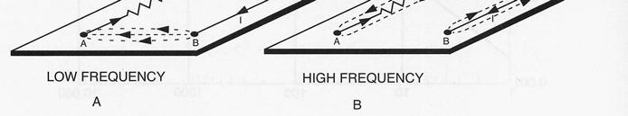
10 Single-Point Ground Systems Single-point grounds are most effectively used at low frequencies, dc up to 20 khz. With single-point grounding, we control the ground topology to direct the ground current to flow where we want it to flow, which decreases in the sensitive portion of the ground. I g 10
11 A V I I I Z = ( ) 1 VC = ( I1+ I2 + I3) Z1+ ( I2 + I3) Z2 + I3Z3 This circuit is least desirable single-point grounding system, but it is commonly used because of its simplicity. The configuration should not be used between circuits that operate at widely different e current levels. e When the system is used, the most critical circuit should be the one nearest the primary ground point. 11


12 VA = I1Z1 VC = I3Z3 This system can be mechanically cumbersome. Most practical single-point systems are actually a combination of the series and parallel connections. Group ground leads selectively, so that circuits of widely varying power and noise levels do not share the same ground return wire. 12


 and in")
13 At high frequencies, the singlepoint ground system is undesirable because the inductance of the ground conductors increase the ground impedance. Multipoint Ground Systems Multipoint grounds are used at high frequency (above 100 khz) and in digital circuitry. L g Z = R + jωl g g g V = I Z g g g 13

14 In order to minimize L g, ground planes or grids can be used. A good low-inductance ground is necessary on any PCB that contains high-frequency or digital logic circuits. The ground plane provides a lowinductance return for signal currents and allows for the possibility of using constant impedance transmission lines for signal interconnections. 14


15 Common Impedance Coupling I2 V V Z I I L1 = S1 ( ) G 1+ 2 IZ 1 G : intracircuit noise voltage IZ 2 G : intercircuit noise voltage I 1 Common impedance coupling becomes a problem when two or more circuits share a common ground + one or more of the following: 1. A high-impedance ground. 2. A large ground current. 3. A very sensitive, low-noise margin circuit, connected to the ground. Normally, at frequencies < 100 khz, a single-point ground system may be preferable; when > 100 khz, a multipoint i t ground system is best. 15

16 Hybrid Grounds 16
17 When many equipment enclosures must be grounded to the power system ground, but it is desirable to have a single-point signal ground for the circuitry. 17

18 Chassis Grounds Chassis ground is any conductor that is connected to the equipment s metal enclosure. The key to minimizing noise and interference is to determine where and how to connect the signal ground to the chassis. It is important to establish a low-impedance connection between the chassis and the circuit ground in the I/O area of the board. Establishing a low-impedance connection between the circuit ground and the chassis in the I/O area is also advantageous with respect to radio frequency immunity. 18
19 Equipment/System Grounding Introduction Electronic circuits for many systems are mounted in large equipment racks or cabinets. A typical system will consist of one or more of these equipment enclosures. Equipment grounding objectives include electrical safety, lightning protection, EMC control, and signal integrity. Three types of systems will be considered: 1. Isolated systems. 2. Clustered systems. 3. Distributed systems. Isolated Systems An isolated system is one in which all functions are contained within a single enclosure with no external signal connections to other grounded systems. 19


20 Equipment/System Grounding Examples: vending machines, TV sets, component stereo system, desktop computer,. This system is simplest of all systems and the easiest to ground properly. The enclosure ground can be provided by 1. the ac power ground (green wire) when powered by single-phase ac. 2. a separate ground conductor run with the power cable when powered by three-phase ac. Internal signals should be grounded as appropriate for the type of circuitry and frequency of operation. 20
Common Impedance Coupling Effect on Video and Audio Circuitry. Prof. Bogdan Adamczyk Grand Valley State University
 Common Impedance Coupling Effect on Video and Audio Circuitry Prof. Bogdan Adamczyk rand Valley State University Outline 1. Signal ground (signal return path) 2. Objectives of grounding 3. Single- vs.
White Paper: Electrical Ground Rules
 Acromag, Incorporated 30765 S Wixom Rd, Wixom, MI 48393 USA Tel: 248-295-0880 Fax: 248-624-9234 www.acromag.com White Paper: Electrical Ground Rules Best Practices for Grounding Your Electrical Equipment
Application Note (Revision NEW) Original Instructions. EMI Control in Electronic Governing Systems
 Original Instructions. EMI Control in Electronic Governing Systems") Application Note 50532 (Revision NEW) Original Instructions EMI Control in Electronic Governing Systems General Precautions Read this entire manual and all other publications pertaining to the work to
Application Note 50532 (Revision NEW) Original Instructions EMI Control in Electronic Governing Systems General Precautions Read this entire manual and all other publications pertaining to the work to
Chapter 16 PCB Layout and Stackup
 Chapter 16 PCB Layout and Stackup Electromagnetic Compatibility Engineering by Henry W. Ott Foreword The PCB represents the physical implementation of the schematic. The proper design and layout of a printed
Chapter 12 Digital Circuit Radiation. Electromagnetic Compatibility Engineering. by Henry W. Ott
 Chapter 12 Digital Circuit Radiation Electromagnetic Compatibility Engineering by Henry W. Ott Forward Emission control should be treated as a design problem from the start, it should receive the necessary
ECE 528 Understanding Power Quality
 ECE 528 Understanding Power Quality http://www.ece.uidaho.edu/ee/power/ece528/ Paul Ortmann portmann@uidaho.edu 208-316-1520 (voice) 1 Today Wiring and grounding Why it s important References Terms and
Freescale Semiconductor, I
 Order this document by /D Noise Reduction Techniques for Microcontroller-Based Systems By Imad Kobeissi Introduction With today s advancements in semiconductor technology and the push toward faster microcontroller
Power Quality. Case Study. Conrad Bottu Laborelec January 2008
 Case Study Electromagnetic compatibility (EMC) study Breakdown of low voltage electronic equipment in a 25 kv substation Conrad Bottu Laborelec January 2008 Power Quality Power Quality 1 Introduction Description
Understanding the Unintended Antenna Behavior of a Product
 Understanding the Unintended Antenna Behavior of a Product Colin E. Brench Southwest Research Institute Electromagnetic Compatibility Research and Testing colin.brench@swri.org Radiating System Source
Grounding Systems and Their Implementation By: Charles Atkinson Canadian Broadcasting Corporation Toronto, Canada
 Grounding Systems and Their Implementation By: Charles Atkinson Canadian Broadcasting Corporation Toronto, Canada and Philip Giddings Engineering Harmonics Toronto, Canada The original document and figures
Amplifier Series BASIC. Installation & Operations Manual
 Amplifier Series BASIC Installation & Operations Manual Bittner-Audio 200 Power Amplifier Series BASIC Bittner - Audio September 200 200 Bittner-Audio. All Rights Reserved. Bittner-Audio reserves specification
Understanding Noise Cut Transformers
 2014 Understanding Noise Cut Transformers By Quality Transformer and Electronics James Nealon Understanding Noise Cut Transformers By Quality Transformer and Electronics Engineering and Sales Staff Quality
1. Introduction to Power Quality
 1.1. Define the term Quality A Standard IEEE1100 defines power quality (PQ) as the concept of powering and grounding sensitive electronic equipment in a manner suitable for the equipment. A simpler and
The Role of the Grounding System in Electronics Lightning Protection
 ILPS 2016 - International Lightning Protection Symposium April 21-22, 2016 Porto Portugal The Role of the Grounding System in Electronics Lightning Protection Roberto Menna Barreto SEFTIM Brazil Rio de
Overview of the ATLAS Electromagnetic Compatibility Policy
 Overview of the ATLAS Electromagnetic Compatibility Policy G. Blanchot CERN, CH-1211 Geneva 23, Switzerland Georges.Blanchot@cern.ch Abstract The electromagnetic compatibility of ATLAS electronic equipments
KOLLMORGEN. Motion Technologies Group. EMC Installation and Application Guidelines for BDS4/5 Goldline Series MB4000H Issue 3
 KOLLMORGEN Motion Technologies Group EMC Installation and Application Guidelines for BDS4/5 Goldline Series MB4000H Issue 3 CONTENTS DOCUMENT HISTORY 1 DECLARATION OF CONFORMITY 1 1. INTRODUCTION 2 2.
Contents. 1 Introduction. 2 System-Level Electrostatic Discharge (ESD) and Electrical Fast Transient. 3 Electromagnetic Interference
 and Electrical Fast Transient. 3 Electromagnetic Interference") Issue 3, October 2002 Electromagnetic Compatibility and Electrical Safety Contents Telcordia GR-1089 - Documentation Information Generic Requirements Notice Of Disclaimer................. iii Contents.......................................
Issue 3, October 2002 Electromagnetic Compatibility and Electrical Safety Contents Telcordia GR-1089 - Documentation Information Generic Requirements Notice Of Disclaimer................. iii Contents.......................................
To Float or Not to Float? Analysis of a floating vs. grounded output Associated Power Technologies
 To Float or Not to Float? Analysis of a floating vs. grounded output Associated Power Technologies Introduction In electrical circuits, voltage is always measured between two points: a point of high potential
1 Introduction. 1.1 General installation information
 1 Introduction Nearly every electrical component emits electromagnetic radiation during its operation. This has effects on the quality of the useful signals especially at the communication level, in which
Device Interconnection
 Device Interconnection An important, if less than glamorous, aspect of audio signal handling is the connection of one device to another. Of course, a primary concern is the matching of signal levels and
One-day Conference 18 March Power Supply, EMC and Signalling, in Railway Systems
 One-day Conference 18 March 2017 Power Supply, EMC and Signalling, in Railway Systems EMC Management and Related Technical Aspects in Railway Systems By Dr Peter S W LEUNG http://www.ee.cityu.edu.hk/~pswleung/
Overview of Grounding for Industrial and Commercial Power Systems Presented By Robert Schuerger, P.E.
 Overview of Grounding for Industrial and Commercial Power Systems Presented By Robert Schuerger, P.E. HP Critical Facility Services delivered by EYP MCF What is VOLTAGE? Difference of Electric Potential
Research on State Estimation and Information Processing Method for Intelligent Substation
 , pp.89-93 http://dx.doi.org/10.14257/astl.2015.83.17 Research on State Estimation and Information Processing Method for Intelligent Substation Tongwei Yu 1, Xingchao Yang 2 1 Electric Power Research Institute,
Tech Talk (12) Down to Earth: A Discussion of the General Requirements for the Earthing of Control and Instrumentation Systems
 Down to Earth: A Discussion of the General Requirements for the Earthing of Control and Instrumentation Systems") 701880MAC0010.1177/0020294017701880 research-article2017 Contributed Paper Tech Talk (12) Down to Earth: A Discussion of the General Requirements for the Earthing of Control and Instrumentation Systems
701880MAC0010.1177/0020294017701880 research-article2017 Contributed Paper Tech Talk (12) Down to Earth: A Discussion of the General Requirements for the Earthing of Control and Instrumentation Systems
There are many important factors when trying to achieve good, reliable communications between 2 devices.
 APPLICATION NOTE THIS INFORMATION PROVIDED BY AUTOMATIONDIRECT.COM TECHNICAL SUPPORT These documents are provided by our technical support department to assist others. We do not guarantee that the data
Improving the immunity of sensitive analogue electronics
 Improving the immunity of sensitive analogue electronics T.P.Jarvis BSc CEng MIEE MIEEE, I.R.Marriott BEng, EMC Journal 1997 Introduction The art of good analogue electronics design has appeared to decline
Electromagnetic Compatibility ( EMC )
") Electromagnetic Compatibility ( EMC ) Introduction EMC Testing 1-2 -1 Agenda System Radiated Interference Test System Conducted Interference Test 1-2 -2 System Radiated Interference Test Open-Area Test
Electromagnetic Compatibility ( EMC ) Introduction EMC Testing 1-2 -1 Agenda System Radiated Interference Test System Conducted Interference Test 1-2 -2 System Radiated Interference Test Open-Area Test
EE 521: Instrumentation and Measurements
 Aly El-Osery Electrical Engineering Department, New Mexico Tech Socorro, New Mexico, USA October 18, 2009 1 / 18 1 Sources of Coherent Interference Capacitive Coupling Inductive Coupling Ground Loops Power
2-Slot Desktop Chassis (DC) Extended Temperature
 Extended Temperature") APRIL 2008 LMC5202A 2-Slot Desktop Chassis (DC) Extended Temperature Copyright 2008. Black Box Corporation. All rights reserved 50 80105BB 01 A0 1000 Park Drive Lawrence, PA 35055 1018 724 746 5500 Fax
APRIL 2008 LMC5202A 2-Slot Desktop Chassis (DC) Extended Temperature Copyright 2008. Black Box Corporation. All rights reserved 50 80105BB 01 A0 1000 Park Drive Lawrence, PA 35055 1018 724 746 5500 Fax
Industrial and Commercial Power Systems Topic 7 EARTHING
 The University of New South Wales School of Electrical Engineering and Telecommunications Industrial and Commercial Power Systems Topic 7 EARTHING 1 INTRODUCTION Advantages of earthing (grounding): Limitation
Grounding Complications
 Grounding Complications Sensitive Equipment Isolated grounding Supplemental grounds Sensitive Electronic Equipment NEC 647 [2002-2005] Originally intended for audio studios -- now Industrial/commercial
"Natural" Antennas. Mr. Robert Marcus, PE, NCE Dr. Bruce C. Gabrielson, NCE. Security Engineering Services, Inc. PO Box 550 Chesapeake Beach, MD 20732
 Published and presented: AFCEA TEMPEST Training Course, Burke, VA, 1992 Introduction "Natural" Antennas Mr. Robert Marcus, PE, NCE Dr. Bruce C. Gabrielson, NCE Security Engineering Services, Inc. PO Box
CHAPTER 6 EMI EMC MEASUREMENTS AND STANDARDS FOR TRACKED VEHICLES (MIL APPLICATION)
") 147 CHAPTER 6 EMI EMC MEASUREMENTS AND STANDARDS FOR TRACKED VEHICLES (MIL APPLICATION) 6.1 INTRODUCTION The electrical and electronic devices, circuits and systems are capable of emitting the electromagnetic
147 CHAPTER 6 EMI EMC MEASUREMENTS AND STANDARDS FOR TRACKED VEHICLES (MIL APPLICATION) 6.1 INTRODUCTION The electrical and electronic devices, circuits and systems are capable of emitting the electromagnetic
SR Series Crossovers. Owner s Manual SR 823 SR 834. A Harman International Company
 SR Series Crossovers Owner s Manual SR 823 SR 834 A Harman International Company Warning For your protection, please read the following: These symbols are internationally accepted symbols that warn of
Electromagnetic Compatibility Engineering. Henry W. Ott Henry Ott Consultants
 Electromagnetic Compatibility Engineering Henry W. Ott Henry Ott Consultants Electromagnetic Compatibility Engineering Electromagnetic Compatibility Engineering Henry W. Ott Henry Ott Consultants Copyright
Electromagnetic Compatibility Engineering
 Electromagnetic Compatibility Engineering Electromagnetic Compatibility Engineering Henry W. Ott Henry Ott Consultants Copyright r 2009 by John Wiley & Sons, Inc. All rights reserved. Published by John
150Hz to 1MHz magnetic field coupling to a typical shielded cable above a ground plane configuration
 150Hz to 1MHz magnetic field coupling to a typical shielded cable above a ground plane configuration D. A. Weston Lowfreqcablecoupling.doc 7-9-2005 The data and information contained within this report
Los A LA-UR Los Alamos National Laboratory Los Alamos, New Mexico 87545
 LA-UR-98-1 Los Alamos NationalLaboratory is operated by the University of California for the United States Department of Energy under contract W-7405-ENG-36 TITLE: SUBMITTED TO: Electrical Potential Transfer
Considerations in Grounding and Shielding Computer-Controlled Audio Devices
 Considerations in Grounding and Shielding Computer-Controlled Audio Devices Stephen R. Macatee Rane Corporation, Mukilteo. WA 98275-3098. USA Adding computer control to audio devices raises design issues,
Grounding for Power Quality
 Presents Grounding for Power Quality Grounding for Power Quality NEC 250.53 states that ground resistance should be less than 25 ohms. Is this true? Grounding for Power Quality No! NEC 250.53 states
Downloaded from
 -ii- FOREWORD This FAA standard sets forth requirements for the application of transient protection, grounding, bonding, shielding and personnel protection practices to the design, fabrication and assembly
A DUMMIES GUIDE TO GROUND FAULT PROTECTION
 A DUMMIES GUIDE TO GROUND FAULT PROTECTION A DUMMIES GUIDE TO GROUND FAULT PROTECTION What is Grounding? The term grounding is commonly used in the electrical industry to mean both equipment grounding
Overview of EMC Regulations and Testing. Prof. Tzong-Lin Wu Department of Electrical Engineering National Taiwan University
 Overview of EMC Regulations and Testing Prof. Tzong-Lin Wu Department of Electrical Engineering National Taiwan University What is EMC Electro-Magnetic Compatibility ( 電磁相容 ) EMC EMI (Interference) Conducted
GROUNDED ELECTRICAL POWER DISTRIBUTION. Excerpt from Inverter Charger Series Manual BY: VIJAY SHARMA ENGINEER
 GROUNDED ELECTRICAL POWER DISTRIBUTION Excerpt from Inverter Charger Series Manual BY: VIJAY SHARMA ENGINEER .0 Conductors for Electrical Power Distribution For single-phase transmission of AC power or
Table of Contents. 1 Introduction. 2 System-Level Electrostatic Discharge (ESD) and Electrical Fast Transient (EFT) 3 Electromagnetic Interference
 and Electrical Fast Transient (EFT) 3 Electromagnetic Interference") Electromagnetic Compatibility and Electrical Safety GR-1089-CORE Table of Contents Table of Contents 1 Introduction 1.1 Purpose and Scope.................................. 1 1 1.2 Items Not Covered in
Electromagnetic Compatibility and Electrical Safety GR-1089-CORE Table of Contents Table of Contents 1 Introduction 1.1 Purpose and Scope.................................. 1 1 1.2 Items Not Covered in
Facility Grounding & Bonding Based on the EMC/PI/SI Model for a High Speed PCB/Cabinet
 Facility Grounding & Bonding Based on the EMC/PI/SI Model for a High Speed PCB/Cabinet and: SILICON LABS AN203 PRINTED CIRCUIT BOARD DESIGN NOTES www.silabs.com William Bush (wbush@ieee.org) Industry Consultant
EC6011-ELECTROMAGNETICINTERFERENCEANDCOMPATIBILITY
 EC6011-ELECTROMAGNETICINTERFERENCEANDCOMPATIBILITY UNIT-3 Part A 1. What is an opto-isolator? [N/D-16] An optoisolator (also known as optical coupler,optocoupler and opto-isolator) is a semiconductor device
ITU-T K.27. Bonding configurations and earthing inside a telecommunication building SERIES K: PROTECTION AGAINST INTERFERENCE
 I n t e r n a t i o n a l T e l e c o m m u n i c a t i o n U n i o n ITU-T K.27 TELECOMMUNICATION STANDARDIZATION SECTOR OF ITU (03/2015) SERIES K: PROTECTION AGAINST INTERFERENCE Bonding configurations
Grounding and Bonding
 Grounding and Bonding 2017 Communications Academy Joe Blaschka Jr., PE Grounding/Bonding What is it? Why do we do it? What does the National Electrical Code say? What about fixed locations? What about
Designing Your EMI Filter
 The Engineer s Guide to Designing Your EMI Filter TABLE OF CONTENTS Introduction Filter Classifications Why Do We Need EMI Filters Filter Configurations 2 2 3 3 How to Determine Which Configuration to
Electromagnetic Compatibility
 Electromagnetic Compatibility Introduction to EMC International Standards Measurement Setups Emissions Applications for Switch-Mode Power Supplies Filters 1 What is EMC? A system is electromagnetic compatible
Introduction to Electromagnetic Compatibility
 Introduction to Electromagnetic Compatibility Second Edition CLAYTON R. PAUL Department of Electrical and Computer Engineering, School of Engineering, Mercer University, Macon, Georgia and Emeritus Professor
Grounding Recommendations for On Site Power Systems
 Grounding Recommendations for On Site Power Systems Revised: February 23, 2017 2017 Cummins All Rights Reserved Course Objectives Participants will be able to: Explain grounding best practices and code
EMC Overview. What is EMC? Why is it Important? Case Studies. Examples of calculations used in EMC. EMC Overview 1
 EMC Overview What is EMC? Why is it Important? Case Studies. Examples of calculations used in EMC. EMC Overview 1 What Is EMC? Electromagnetic Compatibility (EMC): The process of determining the interaction
AC Motor Drives EMC Standard Installation Guide EMC Compliance Practice
 http://www.delta.com.tw/industrialautomation/ AC Motor Drives EMC Standard Installation Guide EMC Compliance Practice i Preface When an AC motor drive is installed in a noisy environment, radiated and/or
AN1705. Motorola Semiconductor Application Note. Noise Reduction Techniques for Microcontroller-Based Systems. Introduction
 Order this document by /D Motorola Semiconductor Application Note Noise Reduction Techniques for Microcontroller-Based Systems By Imad Kobeissi Introduction With today s advancements in semiconductor technology
2/15/2015. Current will always try to return to its source. In order for there to be current, there must be a complete circuit
 Current will always try to return to its source In order for there to be current, there must be a complete circuit Current will take as many paths or circuits available to it to return to the source The
MDC4500-4B Amplifier/Combiner Data Sheet & User Manual. February Rev 0.95
 MDC4500-4B Amplifier/Combiner Data Sheet & User Manual February 2016 - Rev 0.95 MDC4500-4B Amplifier IMPORTANT SAFETY and USEAGE INFORMATION Please review the following safety precautions to avoid injury
O W N E R S M A N U A L. Po w e r A m p l i f i e r s
 O W N E R S M A N U A L Po w e r A m p l i f i e r s 1.0 Equipment installation Normally your Naim equipment will have been installed by the dealer who sold it to you even if you live outside their immediate
MIL-STD B METRIC 1 Feb 92 SUPERSEDING MIL-STD A 2 FEBRUARY 1984 MILITARY STANDARD GROUNDING, BONDING AND SHIELDING
 METRIC 1 Feb 92 SUPERSEDING MIL-STD-188-124A 2 FEBRUARY 1984 MILITARY STANDARD GROUNDING, BONDING AND SHIELDING for Common Long Haul/Tactical Communication Systems Including Ground Based Communications-
EMC filters. Mounting instructions. Date: January 2006
 Date: January 2006 EPCOS AG 2006. Reproduction, publication and dissemination of this data sheet and the information contained therein without EPCOS prior express consent is prohibited. EMC cannot be assured
Solution of EMI Problems from Operation of Variable-Frequency Drives
 Pacific Gas and Electric Company Solution of EMI Problems from Operation of Variable-Frequency Drives Background Abrupt voltage transitions on the output terminals of a variable-frequency drive (VFD) are
MINIMIZING EMI EFFECTS DURING PCB LAYOUT OF Z8/Z8PLUS CIRCUITS
 APPLICATION NOTE MINIMIZING EMI EFFECTS DURING PCB LAYOUT OF Z8/Z8PLUS CIRCUITS INTRODUCTION The Z8/Z8Plus families have redefined ease-of-use by being the simplest 8-bit microcontrollers to program. Combined
a) Determine the smallest, standard-sized circuit breaker that should be used to protect this branch circuit.
 Determine the smallest, standard-sized circuit breaker that should be used to protect this branch circuit.") ECET4520 Exam II Sample Exam Problems Instructions: This exam is closed book, except for the reference booklet provided by your instructor and one (8.5 x11 ) sheet of handwritten notes that may not contain
ECET4520 Exam II Sample Exam Problems Instructions: This exam is closed book, except for the reference booklet provided by your instructor and one (8.5 x11 ) sheet of handwritten notes that may not contain
2620 Modular Measurement and Control System
 European Union (EU) Council Directive 89/336/EEC Electromagnetic Compatibility (EMC) Test Report 2620 Modular Measurement and Control System Sensoray March 31, 2006 April 4, 2006 Tests Conducted by: ElectroMagnetic
Electromagnetic interference at the mains ports of an equipment
 Electromagnetic interference at the mains ports of an equipment Mircea Ion Buzdugan, Horia Bălan, Emil E. Simion, Tudor Ion Buzdugan Technical University from Cluj-Napoca, 15, Constantin Daicoviciu street,
Tower Grounding Training For Telecommunications Networks
 Tower Grounding Training For Telecommunications Networks Contact us Today for a FREE quotation to deliver this course at your company?s location. https://www.electricityforum.com/onsite-training-rfq The
Electromagnetic Compatibility of Power Converters
 Published by CERN in the Proceedings of the CAS-CERN Accelerator School: Power Converters, Baden, Switzerland, 7 14 May 2014, edited by R. Bailey, CERN-2015-003 (CERN, Geneva, 2015) Electromagnetic Compatibility
EPG. by Chris C. Kleronomos
 April 1994 EFFECTIVE EQUIPMENT GROUNDING ECOS Electronics Corporation by Chris C. Kleronomos The quality of the electrical wiring and grounding in a facility containing sensitive electronic equipment is
Two-Wire Shielded Cable Modeling for the Analysis of Conducted Transient Immunity
 Two-Wire Shielded Cable Modeling for the Analysis of Conducted Transient Immunity Spartaco Caniggia EMC Consultant, Viale Moranti 7, 21 Bareggio (MI), Italy spartaco.caniggia@ieee.org Francesca Maradei
Guidance and Declaration - Electromagnetic Compatibility (EMC) for the Delfi PTS ii Portable Tourniquet System
 for the Delfi PTS ii Portable Tourniquet System") Guidance and Declaration - Electromagnetic Compatibility (EMC) for the Delfi TS ii ortable Tourniquet System Guidance and manufacturer s declaration electromagnetic emissions The TS ii ortable Tourniquet
Guidance and Declaration - Electromagnetic Compatibility (EMC) for the Delfi TS ii ortable Tourniquet System Guidance and manufacturer s declaration electromagnetic emissions The TS ii ortable Tourniquet
Sound System Interconnection Or: Dealing With Ground Loop Hums
 Sound System Interconnection Or: Dealing With Ground Loop Hums Introduction Rane Technical Staff RaneNote 110 written 1985; last revised 12/2009 This note, originally written in 1985, continues to be one
Understanding Design, Installation, and Testing Methods That Promote Substation IED Resiliency for High-Altitude Electromagnetic Pulse Events
 Understanding Design, Installation, and Testing Methods That Promote Substation IED Resiliency for High-Altitude Electromagnetic Pulse Events Tim Minteer, Travis Mooney, Sharla Artz, and David E. Whitehead
MINING EARTH LEAKAGE PROTECTION WITH VARIABLE SPEED DRIVES
 MINING EARTH LEAKAGE PROTECTION WITH VARIABLE SPEED DRIVES White Paper Tim Wylie, Ampcontrol s Chief Technology Officer discusses the impact of Variable Speed Drives (VSDs) on earth fault limited networks.
Power/Ground Isolation and Control in Facilities, Systems, and in System Boxes
 Introduction Power/Ground Isolation and Control in Facilities, Systems, and in System Boxes Bruce C. Gabrielson, PhD Security Engineering Services 5005 Bayside Road Chesapeake Beach, Maryland 20732 Ground
Categorized by the type of core on which inductors are wound:
 Inductors Categorized by the type of core on which inductors are wound: air core and magnetic core. The magnetic core inductors can be subdivided depending on whether the core is open or closed. Equivalent
EDBEMV!PZi. Ä!PZiä. Electromagnetic compatibility. Global Drive Basic information on controller applications in plants and machinery
 EDBEMV!PZi Ä!PZiä L Electromagnetic compatibility Global Drive Basic information on controller applications in plants and machinery 2003 Lenze Drive Systems GmbH Without written approval of Lenze Drive
The Ground Myth IEEE. Bruce Archambeault, Ph.D. IBM Distinguished Engineer, IEEE Fellow 18 November 2008
 The Ground Myth Bruce Archambeault, Ph.D. IBM Distinguished Engineer, IEEE Fellow barch@us.ibm.com 18 November 2008 IEEE Introduction Electromagnetics can be scary Universities LOVE messy math EM is not
CCH400 & CCH600 Series
 CCH4 & CCH6 Series 4 W & 6 W - Baseplate Cooled Compact 8.4 (214 mm) x 4 (12 mm) x 1.69 (43 mm) Package High Efficiency up to 9% -4 C to +85 C Baseplate Operating Temperature No Fan, Quiet Operation MIL-STD-461
AP7301 ELECTROMAGNETIC INTERFERENCE AND COMPATIBILITY L T P C COURSE OBJECTIVES:
 AP7301 ELECTROMAGNETIC INTERFERENCE AND COMPATIBILITY L T P C 3 0 0 3 COURSE OBJECTIVES: To understand the basics of EMI To study EMI Sources To understand EMI problems To understand Solution methods in
MODEL 3810/2 Line Impedance Stabilization Network
 EMC TEST SYSTEMS FEBRUARY 1996 REV C PN 399197 MODEL 3810/2 Line Impedance Stabilization Network OPERATION MANUAL USA P.O. Box 80589 Austin, Texas 78708-0589 2205 Kramer Lane, Austin, Texas 78758-4047
Electromagnetic Interference Mitigation
 Electromagnetic Interference Mitigation Picture or Drawing 20.7 x 8.6 cm Frits J.K. Buesink, Senior Researcher EMC frits.buesink@utwente.nl Funded by the European Union on the basis of Decision No 912/2009/EC,
CM-MPS.11, CM-MPS-21, CM-MPS.31 and CM-MPS.41 Data sheet. UL 508, CAN/CSA C22.2 No.14 GL GOST CB scheme CCC
 2CDC 251 048 F0t08 CM-MPS.11 2CDC 251 049 F0t08 CM-MPS.21 Features Monitoring of three-phase mains for phase sequence (can be switched off), phase failure, over- and undervoltage as well as phase unbalance
Installation/User Manual
 Installation/User Manual APS YC500-A Photovoltaic Grid-connected Inverter Version 4.1 1/15 APS America 1015 Hostmark St. Ste 104; Poulsbo, WA 98370 TEL: 206-855-5100 EMAIL: info@apsamerica.com WEB: www.apsamerica.com
Earthing for EMC in Installations
 Earthing for EMC in Installations Ian McMichael n 1 PQSynergy 2010 Conference Earthing for EMC in Installations Introduction Electromagnetic Compatibility or EMC EMC and installations Standards and References
Protection from electromagnetic environment effects
 ITU Regional Development Forum 2008 Bridging the ICT standardization gap in developing countries Protection from electromagnetic environment effects Roberto Pomponi, ITU-T SG 5 Chairman (Telecom Italia)
Wisconsin Contractors Institute Continuing Education
 IMPORTANT NOTE: You should have received an email from us with a link and password to take your final exam online. Please check your email for this link. Be sure to check your spam folder as well. If you
MDW-45 Converter RS RS-422/485
 www.westermo.com MDW-45 Converter RS-232 - RS-422/485 2 6617-2203 General information Legal information The contents of this document are provided as is. Except as required by applicable law, no warranties
Design for EMI & ESD compliance DESIGN FOR EMI & ESD COMPLIANCE
 DESIGN FOR EMI & ESD COMPLIANCE All of we know the causes & impacts of EMI & ESD on our boards & also on our final product. In this article, we will discuss some useful design procedures that can be followed
BIODEX MULTI- JOINT SYSTEM
 BIODEX MULTI- JOINT SYSTEM CONFORMANCE TO STANDARDS 850-000, 840-000, 852-000 FN: 18-139 5/18 Contact information Manufactured by: Biodex Medical Systems, Inc. 20 Ramsey Road, Shirley, New York, 11967-4704
ECC100 Series. -40 ºC to +75 ºC Operation. 100 W - Baseplate Cooled. High Efficiency Resonant Topology. Screw Terminals Available.
 ECC100 Series -40 ºC to +75 ºC Operation 100 W - Baseplate Cooled High Efficiency Resonant Topology Screw Terminals Available 5V Standby Output Remote On/Off & Power OK Signal 3 Year Warranty The ECC100
INTRODUCTION TO CONDUCTED EMISSION
 IEEE EMC Chapter - Hong Kong Section EMC Seminar Series - All about EMC Testing and Measurement Seminar 2 INTRODUCTION TO CONDUCTED EMISSION By Duncan FUNG 18 April 2015 TOPICS TO BE COVERED Background
Use optocouplers for safe and reliable electrical systems
 1 di 5 04/01/2013 10.15 Use optocouplers for safe and reliable electrical systems Harold Tisbe, Avago Technologies Inc. 1/2/2013 9:06 AM EST Although there are multiple technologies--capacitive, magnetic,
Good RF bonding techniques for cabinets
 Another EMC resource from EMC Standards Good RF bonding techniques for cabinets Helping you solve your EMC problems 9 Bracken View, Brocton, Stafford ST17 0TF T:+44 (0) 1785 660247 E:info@emcstandards.co.uk
Caution - leakage currents! Leakage currents in fault-current protected environments
 Caution - leakage currents! Leakage currents in fault-current protected environments Herbert Blum Product Manager EMC > General situation > Leakage current vs. fault current > Leakage currents from frequency
Thyristor power controller B DI1002 V1.0 Manual/Operating instructions
 1 B DI1002 V1.0 Manual/Operating instructions 2 1 Introduction Before you put the thyristor controller into operation, please read these operating instructions. Keep them in safe place accessible for all
C-Bus DSI Gateway. 5508DSIP Series. Installation Instructions
 C-Bus DSI Gateway 5508DSIP Series Installation Instructions Table of Contents 1.0 Product Range...3 2.0 Description...3 3.0 Capabilities...3 4.0 Compatible Loads...3 5.0 Wiring Instructions...4 6.0 C-Bus
EMI Filters Demystified. By William R. Bill Limburg February 21, 2018 Phoenix Chapter, IEEE EMC Society
 EMI Filters Demystified By William R. Bill Limburg February 21, 2018 Phoenix Chapter, IEEE EMC Society An EMI Filter Defined An EMI filter is a network designed to prevent unwanted electrical conducted
EMC Design Guidelines C4ISR EQUIPMENT & SYSTEMS
 EMC Design Guidelines C4ISR EQUIPMENT & SYSTEMS 1.1. SHIELDING Enclosed structure (equipment box or chassis in outside RF environment) should provide at least 100 db of RF shielding at 1 MHz, 40 db at
11 Myths of EMI/EMC ORBEL.COM. Exploring common misconceptions and clarifying them. MYTH #1: EMI/EMC is black magic.
 11 Myths of EMI/EMC Exploring common misconceptions and clarifying them By Ed Nakauchi, Technical Consultant, Orbel Corporation What is a myth? A myth is defined as a popular belief or tradition that has