MC205 Power Amplifier Owner s Manual
|
|
|
- Walter Caldwell
- 5 years ago
- Views:
Transcription


1 McIntosh Laboratory, Inc. 2 Chambers Street Binghamton, New York MC205 Power Amplifier Owner s Manual Phone:
2 2 The lightning flash with arrowhead, within an equilateral triangle, is intended to alert the user to the presence of uninsulated dangerous voltage within the product s enclosure that may be of sufficient magnitude to constitute a risk of electric shock to persons. WARNING - TO REDUCE RISK OF FIRE OR ELECTRICAL SHOCK, DO NOT EXPOSE THIS EQUIPMENT TO RAIN OR MOISTURE. IMPORTANT SAFETY INSTRUCTIONS! PLEASE READ THEM BEFORE OPERATING THIS EQUIPMENT. 1. Read these instructions. 2. Keep these instructions. 3. Heed all warnings. 4. Follow all instructions. 5. Do not use this apparatus near water. 6. Clean only with a dry cloth. 7. Do not block any ventilation openings. Install in accordance with the manufacturer s instructions. 8. Do not install near any heat sources such as radiators, heat registers, stoves, or other apparatus (including amplifiers) that produce heat. 9. Do not defeat the safety purpose of the polarized or grounding-type plug. A polarized plug has two blades with one wider than the other. A grounding type plug has two blades and a NO USER-SERVICEABLE PARTS INSIDE. REFER SERVICING TO QUALIFIED PERSONNEL. The exclamation point within an equilateral triangle is intended to alert the user to the presence of important operating and maintenance (servicing) instructions in the literature accompanying the appliance. To prevent the risk of electric shock, do not remove cover or back. No user-serviceable parts inside. third grounding prong. The wide blade or the third prong are provided for your safety. If the provided plug does not fit into your outlet, consult an electrician for replacement of the obsolete outlet. 10. Protect the power cord from being walked on or pinched particularly at plugs, convenience receptacles, and the point where they exit from the apparatus. 11. Only use attachments/accessories specified by the manufacturer. 12. Use only with the cart, stand, tripod, bracket, or table specified by the manufacturer, or sold with the apparatus. When a cart is used, use caution when moving the cart/ apparatus combination to avoid injury from tip-over. 13. Unplug this apparatus during lightning storms or when unused for long periods of time. 14. Refer all servicing to qualified service personnel. Servicing is required when the apparatus has been damaged in any way, such as powersupply cord or plug is damaged, liquid has been spilled or objects have fallen into the apparatus, the apparatus has been exposed to rain or moisture, does not operate normally, or has been dropped. 15. Do not expose this equipment to dripping or splashing and ensure that no objects filled with liquids, such as vases, are placed on the equipment. 16. To completely disconnect this equipment from the a.c. mains, disconnect the power supply cord plug from the a.c. receptacle. 17. The mains plug of the power supply cord shall remain readily operable. 18. Do not expose batteries to excessive heat such as sunshine, fire or the like. 19. Connect mains power supply cord only to a mains socket outlet with a protective earthing connection.
3 Thank You Your decision to own this McIntosh MC205 Power Amplifier ranks you at the very top among discriminating music listeners. You now have The Best. The McIntosh dedication to Quality, is assurance that you will receive many years of musical enjoyment from this unit. Please take a short time to read the information in this manual. We want you to be as familiar as possible with all the features and functions of your new McIntosh. Please Take A Moment The serial number, purchase date and McIntosh Dealer name are important to you for possible insurance claim or future service. The spaces below have been provided for you to record that information: Serial Number: Purchase Date: Dealer Name: Technical Assistance If at any time you have questions about your McIntosh product, contact your McIntosh Dealer who is familiar with your McIntosh equipment and any other brands that may be part of your system. If you or your Dealer wish additional help concerning a suspected problem, you can receive technical assistance for all McIntosh products at: McIntosh Laboratory, Inc. 2 Chambers Street Binghamton, New York Phone: Fax: Copyright 2006, 2011 by McIntosh Laboratory, Inc. Customer Service If it is determined that your McIntosh product is in need of repair, you can return it to your Dealer. You can also return it to the McIntosh Laboratory Service Department. For assistance on factory repair return procedure, contact the McIntosh Service Department at: McIntosh Laboratory, Inc. 2 Chambers Street Binghamton, New York Phone: Fax: Table of Contents Safety Instructions...2 Thank You and Please Take a Moment...3 Technical Assistance and Customer Service...3 Table of Contents...3 General Information Connector and Cable Information...4 Introduction...4 Performance Features...4 Dimensions...5 Installation...6 Connections: Rear Panel Connections...7 How to Connect for a Five Channel System Connection Diagram (Separate Sheet)...Mc1A How to Connect for a Five Channel and Zone B System (or Seven Channel System) Connection Diagram (Separate Sheet)...Mc1B Front Panel Displays and Controls...12 How to Operate...13 Technical Description Photos Specifications Packing Instruction...19 General Information 1. For additional connection information, refer to the owner s manual(s) for any component(s) connected to the MC205 Power Amplifier. 2. The Main AC Power going to the MC205 and any other McIntosh Component(s) should not be applied until all the system components are connected together. Failure to do so could result in malfunctioning of some or all of the system s normal operations. When the MC205 and other McIntosh Components are in their Standby Power Off Mode, some of the circuitry inside each component is active and communication is occurring between them. 3. In the event the MC205 overheats, due to improper ventilation and/or high ambient temperature, the protection circuits will activate. The Front Panel Power Guard LEDs will continuously indicate ON and the audio will be muted. When the MC205 has returned to a safe operating temperature, normal operation will resume. 4. For the best performance and safety it is important to always match the impedance of the Loudspeaker to the Power Amplifier connections. Refer to How to Connect pages 8 thru 11. Note: The impedance of a Loudspeaker actually varies as the Loudspeaker reproduces different frequencies. As a result, the nominal impedance rating of the Loudspeaker (usually measured at a midrange frequency) might not always agree with the impedance of the Loudspeaker at low frequencies where the greatest amount of power is required. Contact the Loudspeaker Manufacturer for additional information about the actual impedance of the Loudspeaker before connecting it to the McIntosh MC205. 3
4 General Information, con,t and Cable Information, Introduction and Performance Features General Information, con t 5. When discarding the unit, comply with local rules or regulations. Batteries should never be thrown away or incinerated but disposed of in accordance with the local regulations concerning battery disposal. 6. For additional information on the MC205 and other McIntosh Products please visit the McIntosh Web Site at Connector and Cable Information XLR Connectors Below is the Pin configuration for the XLR Balanced Input Connectors on the MC205. Refer to the diagram for connection: PIN 1: Shield/Ground PIN 2: + Output PIN 3: - Output Power Control Connector The MC205 s Power Control Inputs receive On/Off signals of +5 volts. An additional connection is for controlling the illumination of the MC205 Power Output Meters. The 1/8 inch stereo mini phone plug connects to a McIntosh A/V Control Center Power Control Output. Note: The Power Control Connecting Cable is available from the McIntosh Parts Department: PIN 1 PIN 2 PIN 3 Power Control Meter Illumination Control Ground Data and Power Control Cable Part No Six foot, shielded 2 conductor, with 1/8 inch stereo mini phone plugs on each end. Introduction Now you can take advantage of traditional McIntosh standards of excellence in the MC205 Power Amplifier. The five channel Power Amplifier produces a power output of 200 watts per channel and will drive quality Loudspeakers to a high level of performance. The MC205 reproduction is sonically transparent and absolutely accurate. The McIntosh Sound is The Sound of the Music Itself. Performance Features Power Output The MC205 consists of five Power Amplifier Channels, each capable of 200 watts into 4 ohm or 8 ohm Loudspeakers with less than 0.005% distortion. Power Guard The patented McIntosh Power Guard Circuit prevents the amplifier from being over driven into clipping, with its harsh distorted sound that can damage your valuable Loudspeakers. Dynamic Power Manager TM The MC205 s Dynamic Power Manager (DPM) circuitry allows for the connection of either 4 ohm or 8 ohm Loudspeakers, while at the same time delivering identical power output. A peak output current of 25 amperes per channel ensures that it will successfully drive high quality Loudspeakers such as McIntosh, for a truly exciting sound experience. Balanced and Unbalanced Inputs Balanced connections guard against induced noise and allow long cable runs without compromising sound quality. Sentry Monitor and Thermal Protection McIntosh Sentry Monitor power output stage protection circuits ensure the MC205 will have a long and trouble free operating life. Built-in thermal protection circuits guard against overheating. Illuminated Power Meters The Illuminated Power Output Watt Meters on the MC205 are peak responding, and indicate the power output of the amplifier. Power Control The McIntosh Power Control Circuit allows for remote turn-on of the MC205 Power Amplifier from a McIntosh A/V Control Center or Preamplifier for a single or dual Zone System. Special Power Supply A regulated Power Supply and a very large Toroidal Wound Power Transformer, ensures stable noise free operation even though the power line varies. Fiber Optic Solid State Front Panel Illumination The even Illumination of the Front Panel is accomplished by the combination of custom designed Fiber Optic Light Diffusers and extra long life Light Emitting Diodes (LEDs). The glass Front Panel ensures the pristine beauty of the MC205 will be retained for many years. 4
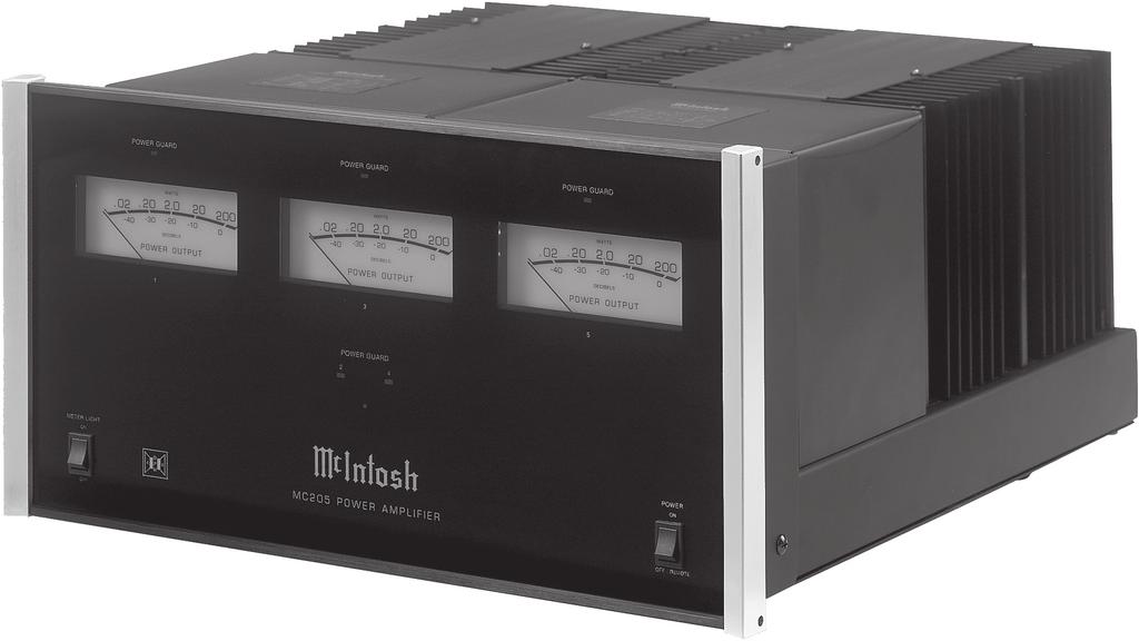
5 Dimensions Dimensions The following dimensions can assist in determining the best location for your MC205. Front View of the MC /2" 44.45cm 8-7/8" 22.54cm 9-7/16" 23.97cm Side View of the MC /4" 47.63cm 16-7/16" 41.75cm Rear View of the MC /16" 42.70cm 3/16" 0.48cm 8-1/4" 20.96cm 7/8" 2.22cm 12" 30.48cm 2" 5.08cm 11-3/4" 29.85cm 5
6 Installation Installation The MC205 can be placed upright on a table or shelf, standing on its four feet. It also can be custom installed in a piece of furniture or cabinet of your choice. The four feet may be removed from the bottom of the MC205 when it is custom installed as outlined below. The four feet together with the mounting screws should be retained for possible future use if the MC205 is removed from the custom installation and used free standing. The required panel cutout, ventilation cutout and unit dimensions are shown. Always provide adequate ventilation for your MC205. Cool operation ensures the longest possible operating life for any electronic instrument. Do not install the MC205 directly above a heat generating component such as a high powered amplifier. If all the components are installed in a single cabinet, a quiet running ventilation fan can be a definite asset in maintaining all the system components at the coolest possible operating temperature. A custom cabinet installation should provide the following minimum spacing dimensions for cool operation. Allow at least 6 inches (15.24cm) above the top, 2 inches (5.08cm) below the bottom and 1 inch (2.54cm) on each side of the Power Amplifier, so that airflow is not obstructed. Allow 19-1/2 inches (49.53cm) depth behind the front panel. Allow 7/8 inch (2.22cm) in front of the mounting panel 1 for clearance. Be sure to cut out a ventilation hole in the mounting shelf according to the dimensions in the drawing. 1 When the MC205 is installed together with other McIntosh Components, check clearances on all components before proceeding. MC205 Front Panel Custom Cabinet Cutout MC205 Side View in Custom Cabinet MC205 Bottom View in Custom Cabinet Cabinet Front Panel Opening for Ventilation Support Shelf Center the opening horizontally with the MC205 Chassis 17-1/16" 43.34cm 6" 15.24cm Cutout Opening for Ventilation 3-3/4" 8.57cm 12-1/4" 31.12cm Cutout Opening for Ventilation 9-7/8" 25.08cm Cutout Opening for Custom Mounting 15-3/4" 40.00cm 11" 27.9cm Chassis Spacers 12-3/8" 31.43cm 8-5/16" 21.11cm 11-1/2" 29.21cm 6
7 Rear Panel Connections and Switch OUTPUT Connections for a 4 ohm or 8 ohm Loudspeaker for Channel 2 (Left Surround) or ZONE B Left Channel OUTPUT Connections for a 4 ohm or 8 ohm Loudspeaker for Channel 5 (Right Front) Selects the impedance (4 or 8 ohms) of the Loudspeakers connected to the MC205 POWER CONTROL ZA receives turn On/ Off signals from a McIntosh component for Zone A (Channels 1-5). ZB receives turn On/Off signals from a McIntosh component for Zone B (Channels 2 and 4). OUTPUT Connections for a 4 ohm or 8 ohm Loudspeaker for Channel 1 (Left Front) OUTPUT Connections for a 4 ohm or 8 ohm Loudspeaker for Channel 4 (Right Surround) or ZONE B Right Channel OUTPUT Connections for a 4 ohm or 8 ohm Loudspeaker for Channel 3 (Center Front) Connect the MC205 power cord to a live AC outlet. Refer to the rear panel to determine the correct voltage Balanced INPUT Channel 1 (Left Front) Balanced INPUT Channel 4 (Right Surround) or ZONE B Right Channel Balanced INPUT Channel 2 (Left Surround) or ZONE B Left Channel Balanced INPUTS Channel 5 (Right Front) and Channel 3 (Center Front) Main Fuse, refer to the rear panel for the correct fuse size and rating Unbalanced INPUTs Channel 2 (Left Surround) and Channel 4 (Right Surround) or ZONE B Left and Right Channels Unbalanced INPUT Channel 5 (Right Front) Unbalanced INPUTs Channel 1 (Left Front) and Channel 3 (Center Front) 7
8 How to Connect for a Five Channel System Caution: Do not connect the AC Power Cord to the MC205 Rear Panel until after the Loudspeaker Connections are made and the protective Terminal Connections Cover is installed. Failure to observe this could result in Electric Shock. The connection instructions below, together with the MC205 Connection Diagram located on the separate folded sheet Mc1A, is an example of a typical Multichannel System. Your system may vary from this, however the actual components would be connected in a similar manner. For additional information refer to Connector and Cable Information on page For Remote Power Control, connect a power control cable from the A/V Control Center Power Control Trigger/Output 1 to the Amplifier POWER CON- TROL ZA input. 2. Connect XLR cables from the Balanced Outputs (FL, C, FR, SR and SL) of an A/V Control Center to the MC205 Balanced INPUTS (1-LF, 3-CTR, 5-RF, 4-RS and 2-LS) making sure to match up channel designation. Note: Unbalanced cables and connections may be used instead of Balanced connections. This McIntosh MC205 Power Amplifier is designed for Loudspeakers with an impedance of 4 ohms or 8 ohms. Connect a single Loudspeaker only to each Channel Output Terminals. When connecting Loudspeakers to the MC205 it is very important to use cables of adequate size, so there is little to no power loss in the cables. The size is specified in Gauge Numbers or AWG (American Wire Gauge). The smaller the Gauge number, the larger the wire size: Loudspeaker Cable Distance vs Wire Gauge Guide Loudspeaker Impedance 25 feet (7.62 meters) or less 50 feet (15.24 meters) or less 100 feet (30.48 meters) or less 2 Ohms 12AWG 10AWG 8AWG 4 Ohms 14AWG 12AWG 10AWG 8 Ohms 16AWG 14AWG 12AWG 3. Prepare the Loudspeaker Hookup Cable for attachment to the MC205 Power Amplifier: Bare wire cable ends: Carefully remove sufficient insulation from the cable ends, refer to figures 1, 2 & 3. If the cable is stranded, carefully twist the strands together as tightly as possible. Figure 1 Figure 2 Figure 3 Notes: 1. If desired, the twisted ends can be tinned with solder to keep the strands together. 2. The prepared bare wire cable ends may be inserted into spade lug connectors. 3. Banana plugs are for use in the United States and Canada only. Banana Plugs are for use in the United States and Canada only: 4. Attach the previously prepared bare wire cable ends into the banana plugs and secure the connections. Refer to figure 4. Figure 4 5. Referring to figure 5, connect the Loudspeaker hookup cables with banana plugs into the hole at the end of the MC205 Negative and Positive Output Terminals. 6. Place the IMPEDANCE Switch to Figure 5 the position (4 ohm or 8 ohm) to match the impedance of the connected Loudspeakers. In the event that some of the Loudspeakers in the system are different impedance, use the impedance of the Front Loudspeakers. If the Loudspeaker s impedance is 6 ohms, select the 4 ohms setting. Refer to General Information Note 4 on page 3 for additional information. WARNING: Loudspeaker terminals are hazardous live and present a risk of electric shock. For additional instruction on making Loudspeaker Connections contact your McIntosh Dealer or McIntosh Technical Support. 7. Connect the MC205 power cord to an active AC outlet. Spade Lug or Wire Connections: 8. Connect the Loudspeaker hookup cables to the MC205 Output Terminal being careful to observe the correct polarities. Insert the spade lug connector or prepared section of the cable end into the terminal side access hole., Then tighten the terminal cap until the cable is firmly clamped into the terminals so the lugs or wire cannot slip out. Refer to figures 6, 7 and 8. 8
9 How to Connect for a Five Channel System Figure 6 Figure 7 Figure 8 9. Place the IMPEDANCE Switch to the position (4 ohm or 8 ohm) to match the impedance of the connected Loudspeakers. In the event that some of the Loudspeakers in the system are different impedance, use the impedance of the Front Loudspeakers. If the Loudspeaker s impedance is 6 ohms, select the 4 ohms setting. Refer to General Information Note 4 on page 3 for additional information. WARNING: Loudspeaker terminals are hazardous live and present a risk of electric shock. For additional instruction on making Loudspeaker Connections contact your McIntosh Dealer or McIntosh Technical Support. 10. Connect the MC205 power cord to an active AC outlet. 9
10 How to Connect for a Five Channel and Zone B System (or Seven Channel System) Caution: Do not connect the AC Power Cord to the MC205 Rear Panel until after the Loudspeaker Connections are made and the protective Terminal Connections Cover is installed. Failure to observe this could result in Electric Shock. The connection instructions below, together with the MC205 Connection Diagram located on the separate folded sheet Mc1B. Below is an example of a typical Five Channel and Zone B System (or Seven Channel System). Your system may vary from this, however the actual components would be connected in a similar manner. For additional information refer to Connector and Cable Information on page For Remote Power Control, connect a power control cable from the A/V Control Center Power Control Trigger/Output 1 to Power Amplifier Two, Power Control In. 2. Connect a power control cable from Power Amplifier Two, Power Control Out to the MC205 POWER CONTROL ZA Input. 3. Connect a power control cable from the A/V Control Center Power Control Trigger/Output 2 to the MC205 Power Amplifier ZB Input. Note: Do not perform this step in a Seven Channel System. 4. Connect XLR cables from the Balanced Outputs (FL and FR) of an A/V Control Center to Power Amplifier Balanced Left and Right Inputs, making sure to match up channel designation. Note: Unbalanced cables and connections may be used instead of Balanced connections. 5. Connect XLR cables from the Balanced Outputs (C, SR and SL) of an A/V Control Center to the MC205 Balanced INPUTS (3-CTR, 4-RS and 2-LS), making sure to match up channel designation. 6. Connect audio cables from the A/V Control Center Zone B Left and Right Channel Outputs to the MC205 Unbalanced 2-LS and 4-RS, making sure to match up channel designation. Note: In a Seven Channel System perform step 6 instead of step In a Seven Channel System, connect XLR cables from the Balanced Outputs (SBL and SBR) of an A/V Control Center to the MC205 Balanced IN- PUTS (5-RF and 1-LF), making sure to match up channel designation. This McIntosh MC205 Power Amplifier is designed for Loudspeakers with an impedance of 4 ohms or 8 ohms. Connect a single Loudspeaker only to each Channel Output Terminals. When connecting Loudspeakers to the MC205 it is very important to use cables of adequate size, so there is little to no power loss in the cables. The size is specified in Gauge Numbers or AWG (American Wire Gauge). The smaller the Gauge number, the larger the wire size: Loudspeaker Cable Distance vs Wire Gauge Guide Loudspeaker Impedance 25 feet (7.62 meters) or less 50 feet (15.24 meters) or less 100 feet (30.48 meters) or less 2 Ohms 12AWG 10AWG 8AWG 4 Ohms 14AWG 12AWG 10AWG 8 Ohms 16AWG 14AWG 12AWG 8. Prepare the Loudspeaker Hookup Cable for attachment to the MC205 Power Amplifier: Bare wire cable ends: Carefully remove sufficient insulation from the cable ends, refer to figures 1, 2 & 3. If the cable is stranded, carefully twist the strands together as tightly as possible. Figure 1 Figure 2 Figure 3 Notes: 1. If desired, the twisted ends can be tinned with solder to keep the strands together. 2. The prepared bare wire cable ends may be inserted into spade lug connectors. 3. Banana plugs are for use in the United States and Canada only. Banana Plugs are for use in the United States and Canada only: 9. Attach the previously prepared bare wire cable ends into the banana plugs and secure the connections. Refer to figure Referring to figure 5, connect the Loudspeaker hookup cables with banana plugs into the hole at the end of the MC205 Negative and Positive Output Terminals. 11. Place the IMPEDANCE Switch to the position (4 ohm or 8 ohm) to match the impedance of the connected Loudspeakers. Figure 4 Figure 5 In the event that some of the Loudspeakers in the system are different impedance, use the imped- 10
11 How to Connect for a Five Channel and Zone B System (or Seven Channel System) ance of the Front Loudspeakers. If the Loudspeaker s impedance is 6 ohms, select the 4 ohms setting. Refer to General Information Note 4 on page 3 for additional information. WARNING: Loudspeaker terminals are hazardous live and present a risk of electric shock. For additional instruction on making Loudspeaker Connections contact your McIntosh Dealer or McIntosh Technical Support. 12. Connect the MC205 power cord to an active AC outlet. eral Information Note 4 on page 3 for additional information. WARNING: Loudspeaker terminals are hazardous live and present a risk of electric shock. For additional instruction on making Loudspeaker Connections contact your McIntosh Dealer or McIntosh Technical Support. 15. Connect the MC205 power cord to an active AC outlet. Spade Lug or Wire Connections: 13. Connect the Loudspeaker hookup cables to the MC205 Output Terminal being careful to observe the correct polarities. Insert the spade lug connector or prepared section of the cable end into the terminal side access hole. Then tighten the terminal cap until the cable is firmly clamped into the terminals so the lugs or wire cannot slip out. Refer to figures 6, 7 and 8. Figure 6 Figure 7 Figure Place the IMPEDANCE Switch to the position (4 ohm or 8 ohm) to match the impedance of the connected Loudspeakers. In the event that some of the Loudspeakers in the system are different impedance, use the impedance of the Front Loudspeakers. If the Loudspeaker s impedance is 6 ohms, select the 4 ohms setting. Refer to Gen- 11
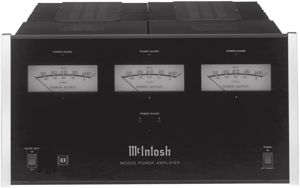
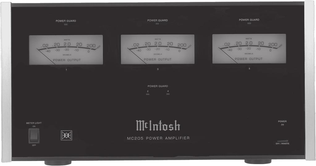
12 Front Panel Displays and Controls LED indicates when Amplifier Channels 1, 3 or 5 POWER GUARD circuit activates Meter indicates the Power Output of the amplifier for Channels 1, 3 and 5 LED indicates when Amplifier Channels 2 or 4 POWER GUARD circuit activates POWER Switch Turns AC Power On or Off/Remote (On/Off) METER LIGHTS Switch selects the Meter Illumination On or Off Standby Power On Indicator 12
13 How to Operate How to Operate Power With the POWER Switch set to the OFF/REMOTE Position, the MC205 will turn On or Off when an A/V Control Center turns On or Off. For manual operation, place the POWER Switch to the ON Position as desired. Refer to figure 9. Note: There must be a power control connection between the MC205 and the McIntosh A/V Control Center in Figure 9 order for the remote power turn-on to function. Meter Illumination Place the METER LIGHTS Switch to the ON position for Illuminated Meters or place the switch to the Off position for no Illumination. When Power Control Input ZA (Zone A only) of the MC205 is connected to a McIntosh A/V Control Center or Preamplifier with Remote Meter Illumination Control, the Meter Illumination will automatically be remotely controlled (On/Off) with the METER LIGHTS Switch to set to the ON position. Refer to Figure 10 figure 10. In the event that some of the Loudspeakers in the system are of different impedance, use the impedance of the Left and Right Front Loudspeakers to set the IMPEDANCE Switch position. Figure 12 Refer to figure 12. Power Output Meters The MC205 Power Output Meters are calibrated to allow for the direct reading of either the Power Output in Watts or Decibels for Loudspeakers connected to Channels 1, 3 and 5. The meters respond to all the musical information being produced by the amplifier. They indicate to an accuracy of at least 95% of the power output with only a single cycle of a 2000Hz tone burst. Refer to figure 13. Figure 13 Impedance Switch The MC205 s Dynamic Power Manager circuitry allows for the connection of either 4 ohm or 8 ohm Loudspeakers to its output terminals, while at the same time delivering the same power output. Refer to figure 11. Place the IMPEDANCE Switch, located on the rear panel, to the position (4 ohm Figure 11 or 8 ohm) that matches the impedance of the connected Loudspeakers. 13

14 Technical Description A continuous average power output rating of 200 watts and an output current of greater than 25 amperes per channel, makes this one of the most advanced and powerful amplifiers McIntosh has ever manufactured. Refer to figures 14 and 15. The distortion limits for the MC205 are no more than 0.005% at rated power output for all frequencies from 20Hz to 20,000Hz. Typical performance at mid frequencies is less than 0.002%. The true distortion readings on the MC205 are so low, it takes special measuring techniques to make accurate readings. The MC205 can deliver the best possible performance from any type of high quality Loudspeaker System. Design Philosophy The MC205 McIntosh Power Amplifier to uses the recently developed Dynamic Power Manager TM (DPM) Circuitry. The MC205 can easily drive 4 ohm speakers, with their high current demand. Additionally, the MC205 can be used with 8 ohm speakers, and deliver equal power. McIntosh s new DPM TM design enables it to run on higher voltage rails when connected to less current-hungry 8 ohm speakers and still deliver 200 watts. The power penalty usually paid with 8 ohm speakers on high current amplifiers does not exist with this new design. The high efficiency circuit design of the MC205 contributes to low operating temperatures. More than 2100 square inches of heat sink area occupies almost half of the MC205 s chassis space and keeps the amplifier operating safely with convection cooling. No fans are needed. Protection Circuits The MC205 incorporates its version of the McIntosh Sentry Monitor output transistor protection circuit. There is absolutely no compromise in sonic performance with this circuit, and it ensures safe operation of the amplifier under even the most extreme operating conditions. Refer to figure 16. The different types of protection circuits incorporated in the Normal Operating Area Sentry Monitor Safety Area Figure 16 Output Transistor Failure MC205 insure a long and safe operating life. The MC205 also includes the unique patented McIntosh Power Guard circuit. Power Guard eliminates the possibility of ever overdriving the amplifier into clipping. Refer to figures 17, 18 and 19. An Block Diagram of the Power Amplifier (one channel shown) Figure 14 Figure 15 14


, the Power Guard activates the PG light and a dynamic electronic attenuator at the amplifier input reduces the input volume just enough to prevent any further increase in")

15 Technical Description overdriven amplifier can Input Test Signal produce both audible and inaudible distortion levels exceeding 40%. The audible distortion is unpleasant to hear, but the inaudible ultrasonic distortion is also undesirable, since it can damage valuable Loudspeaker System tweeters. You will never Figure 17 experience the harsh Without Power Guard and damaging distortion due to clipping. The Power Guard circuit is a waveform comparator, monitoring both the input and output waveforms. Under normal operating conditions, there are no differences between the shape of these waveforms. If an amplifier channel is Figure 18 overdriven, there will be a difference between the two signal waveforms. When the difference exceeds 0.3% (equivalent to 0.3% harmonic distortion), the Power Guard activates the PG light and a dynamic electronic attenuator at the amplifier input reduces the input volume just enough to prevent any further increase in distortion. The Power Guard circuit acts so fast that there are absolutely no audible side effects and the sonic purity of the music reproduction is perfectly preserved. The MC205 Power Amplifier with Power Guard is not limited to just the rated power output, but will actually produce distortion free output well above its rated power due to the McIntosh philosophy of conservative design. Power Supply Circuits To compliment the design of the MC205, there is a high current power supply for the five power amplifier channels. Refer to figure 20. The very large Power Transfomer, has toroidal windings on a toroidal core and can supply over 35 amps of continuous current. Refer to figure 21 (golf ball is for size comparsion). It is enclosed in the legendary McIntosh Potted Enclosures and weighs over 12.06kg. The super size main filter capacitors can store over 310 Joules of energy for the five amplifier channels, necessary for the wide dynamic range that Digital Audio demands. The power amplifier draws high current from the AC power line. Block Diagram of the Power Supply With Power Guard Figure 19 Figure 20 Figure 21 Therefore, it is important that they plug directly into the wall outlet. Also, most owners desire one power switch for the whole audio system. The MC205 is equipped with a circuit that provides remote Power Control from a McIntosh A/V Control Center. When the A/V Control Center is switched On, a (+5V) signal operates the power relay in the MC205. The MC205 also has a remote Power Control input for Zone B operation (two of the five channels). 15
16 16

17 Photos 17
18 Specifications Specifications Power Output Minimum sine wave continuous average power output per channel, all channels operating is: 200 watts into a 4 ohm or 8 ohm load Output Load Impedance 8 and 4 ohms Rated Power Band 20Hz to 20,000Hz Total Harmonic Distortion 0.005% maximum harmonic distortion at any power level from 250 milliwatts to rated power, 20Hz to 20,000Hz Dynamic Headroom 1.7dB Frequency Response +0, -0.25dB from 20Hz to 20,000Hz +0, -3dB from 10Hz to 100,000Hz Input Sensitivity (for rated output) 2.0 Volt Balanced with a 4 ohm Loudspeaker 1.0 Volt Unbalanced with a 4 ohm Loudspeaker 2.8 Volt Balanced with a 8 ohm Loudspeaker 1.4 Volt Unbalanced with a 8 ohm Loudspeaker Signal To Noise Ratio (A-Weighted) 112dB below rated output Intermodulation Distortion 0.005% maximum, if the instantaneous peak power output is rated power or less per channel with all channels operating for any combination of frequencies from 20Hz to 20,000Hz. Wide Band Damping Factor Greater than 70 at 4 ohms Greater than 140 at 8 ohms Input Impedance 20,000 ohms Balanced 10,000 ohms Unbalanced Power Guard Less than 2% THD with up to 14dB overdrive at 1,000Hz Power Requirements 100 Volts, 50/60Hz at 12 Amps 110 Volts, 50/60Hz at 11 Amps 120 Volts, 50/60Hz at 10 Amps 220 Volts, 50/60Hz at 6 Amps 230 Volts, 50/60Hz at 6 Amps 240 Volts, 50/60Hz at 6 Amps Note: Refer to the rear panel of the MC205 for the correct voltage. Overall Dimensions Width is 17-1/2 inches (44.45cm) Height is 9-7/16 inches (23.97cm) including feet Depth is 21 inches (53.3cm) including the Front Panel and Cables Weight 81 pounds (44.2 kg) net, 114 pounds (51.8 kg) in shipping carton Shipping Carton Dimensions Width is 29-1/2 inches (74.93cm) Depth is 30-1/2 inches (77.47cm) Height is 17-1/2 inches (44.45cm) 18
19 Packing Instructions Packing Instructions In the event it is necessary to repack the equipment for shipment, the equipment must be packed exactly as shown below. It is very important that the four plastic feet are attached to the bottom of the equipment. Four 1/4-20 x 2-1/2 inch screws and washers must be used to fasten the unit securely to the bottom pad and shipping skid. This will ensure the proper equipment location on the bottom pad. Failure to do this will result in shipping damage. Use the original shipping carton and interior parts only if they are all in good serviceable condition. If a shipping carton or any of the interior part(s) are needed, please call or write Customer Service Department of McIntosh Laboratory. Please see the Part List for the correct part numbers. Quantity Part Number Description Shipping carton top Shipping carton bottom Foam Pad (top and bottom) Foam Pad (front and rear) Foam Pad (sides) Inner carton top Inner carton bottom Foam Pad (inner carton) Shipping skid /4-20x2-1/4 cap screw Flat washer 19


20 McIntosh Laboratory, Inc. 2 Chambers Street Binghamton, NY The continuous improvement of its products is the policy of McIntosh Laboratory Incorporated who reserve the right to improve design without notice. Printed in the U.S.A. McIntosh Part No
MC75 Tube Power Amplifier Owner s Manual
 McIntosh Laboratory, Inc. 2 Chambers Street Binghamton, New York MC75 Tube Power Amplifier Owner s Manual 13903-2699 Phone: 607-723-3512 www.mcintoshlabs.com 2 The lightning flash with arrowhead, within
Power Amplifier. MC501 Owner s Manual
 Power Amplifier MC501 Owner s Manual McIntosh Laboratory, Inc. 2 Chambers Street Binghamton, New York 13903-2699 Phone: 607-723-3512 FAX: 607-724-0549 The lightning flash with arrowhead, within an equilateral
Power Amplifier. MC252 Owner s Manual
 Power Amplifier MC252 Owner s Manual McIntosh Laboratory, Inc. 2 Chambers Street Binghamton, New York 13903-2699 Phone: 607-723-3512 FAX: 607-724-0549 The lightning flash with arrowhead, within an equilateral
MC312 Power Amplifier Owner s Manual
 McIntosh Laboratory, Inc. 2 Chambers Street Binghamton, New York MC312 Power Amplifier Owner s Manual 13903-2699 Phone: 607-723-3512 www.mcintoshlabs.com Important Safety Information is supplied in a separate
a315 power amplifier Owner s Manual
 Wadia Digital, LLC. 2 Chambers Street Binghamton, New York 13903-2699 Phone: 607-723-3539 Fax: 607-724-0549 www.wadia.com a315 power amplifier Owner s Manual 2 The lightning flash with arrowhead, within
MC302 Power Amplifier Owner s Manual
 McIntosh Laboratory, Inc. 2 Chambers Street Binghamton, New York MC302 Power Amplifier Owner s Manual 13903-2699 Phone: 607-723-3512 www.mcintoshlabs.com 2 The lightning flash with arrowhead, within an
MC462 Quad Balanced Power Amplifier Owner s Manual
 McIntosh Laboratory, Inc. 2 Chambers Street Binghamton, New York MC462 Quad Balanced Power Amplifier Owner s Manual 13903-2699 Phone: 607-723-3512 www.mcintoshlabs.com Important Safety Information is supplied
Power Controller. MPC1500 Owner s Manual. Torus Power Technology under license from Plitron Manufacturing Inc.
 Power Controller MPC1500 Owner s Manual Torus Power Technology under license from Plitron Manufacturing Inc. McIntosh Laboratory, Inc. 2 Chambers Street Binghamton, New York 13903-2699 Phone: 607-723-12
MC58 Eight Channel Power Amplifier
 Owner s Manual MC58 Eight Channel Power Amplifier MC58 McIntosh Laboratory, Inc. 2 Chambers Street Binghamton, New York 13903-2699 Phone: 607-723-3512 FAX: 607-724-0549 The lightning flash with arrowhead,
2BSST POWER AMPLIFIER OWNER S MANUAL
 2BSST POWER AMPLIFIER OWNER S MANUAL IMPORTANT SAFETY INSTRUCTIONS The lightning flash with arrowhead symbol within an equilateral triangle, is intended to alert the user to the presence of un-insulated
A Channel Amplifier
 Installation Manual A2150 2 Channel Amplifier Table of Contents Installation Requirements and Recommendations 1 What s included 1 Speaker Wire Recommendations 1 Setup 2 Rack Mounting 2 Individually Protected
M-300 Mono power amplifier User s guide
 M-300 Mono power amplifier User s guide M-300 Mono power amplifier User s guide Specifications: Contents: Power output: 8Ω: 290W, 0.01% THD SPECIFICATIONS Page 2 Input impedance: Gain: 4Ω: 580W, 0.01%
REVAMP4100 Instruction manual
 REVAMP4100 Instruction manual REVAMP4100 Instruction manual 3 REVAMP4100 manual 4 CLASS-D POWER AMPLIFIER IMPORTANT SAFETY INSTRUCTIONS 1. Read these instructions 2. Keep these instructions 3. Heed all
ECA COMMERCIAL AMPLIFIER OWNER S MANUAL ECA-70MIXAMP V / 70V / 4Ω Amplifier ECA-70MIXAMP-1-60 OUTPUT LEVEL POWER MASTER MIC 1
 OWNER S MANUAL ECA COMMERCIAL AMPLIFIER ECA-MIXAMP--6 V / V / Ω Amplifier TEMP PROT OUTPUT LEVEL ECA-MIXAMP--6 6 POWER MIC MIC MIC MIC AUX AUX BASS TREBLE 5 5 5 5 5 6 6 6 6 6 MASTER 5 6 ON OFF + - + -
REVAMP4120T Instruction manual
 REVAMP4120T Instruction manual REVAMP4120T Instruction manual 3 REVAMP4120T manual 4 CLASS-D POWER AMPLIFIER IMPORTANT SAFETY INSTRUCTIONS 1. Read these instructions 2. Keep these instructions 3. Pay
KLASIK NEAR FIELD ACTIVE STUDIO MONITOR
 USER S MANUAL KLASIK NEAR FIELD ACTIVE STUDIO MONITOR CONTENTS page INTRODUCTION GENERAL INFORMATION 3 REAR PANEL REAR PANEL 4 INPUTS 5 SWITCHES 5 TECHNICAL SPECIFICATIONS TECHNICAL SPECIFICATIONS 7 SAFETY
R-Series R235LS 2-Channel Power Amplifier with Local Source Switching
 R-Series R235LS 2-Channel Power Amplifier with Local Source Switching User s Manual On Off R235LS POWER A MPLIFIER IMPORTANT SAFEGUARDS WARNING TO REDUCE THE RISK OF FIRE OR ELECTRIC SHOCK, DO NOT EXPOSE
MC1000 POWER AMPLIFIER
 MC1000 POWER AMPLIFIER MC1000 POWER AMPLIFIER IMPORTANT SAFETY INSTRUCTIONS THESE INSTRUCTIONS ARE TO PROTECT YOU AND THE MclNTOSH INSTRUMENT. BE SURE TO FAMILIARIZE YOURSELF WITH THEM Copyright 1992
HTA125A/250A. Power Amplifiers. Installation & Use Manual
 HTA125A/250A Power Amplifiers Installation & Use Manual Specifications subject to change without notice. 2010 Bogen Communications, Inc. All rights reserved. 54-5832-04B 1011 NOTICE: Every effort was made
A32. f u l l y b a l a n c e d p o w e r a m p l i f i e r. user guide
 A32 f u l l y b a l a n c e d p o w e r a m p l i f i e r user guide Welcome! Welcome to the Primare A32 Amplifier! The A32 is a modular power amplifier designed as the ideal output stage in a home theatre
STEREO POWER AMPLIFIER OWNER MANUAL PR-150 DESIGNED IN U.K. PDF created with FinePrint pdffactory trial version
 STEREO POWER AMPLIFIER OWNER MANUAL PR-150 DESIGNED IN U.K. INTRODUCTION Congratulations on your purchase of MA PR-150 Stereo Power Amplifier. The performance of PR-150 is perfect for any audio application,
plifier D-501 otion Am Tactile M
 Tactile Motion Amplifier D-501 IMPORTANT SAFETY INSTRUCTIONS WARNING: 1. Read and keep these instructions for future reference. 2. Do not use this apparatus near water. 3. Clean only with a dry cloth.
Big Bang. B B O w n e r s M a n u a l. Power Amplifiers. SpeakerCraft BB2125 POWER ACTIVE PROTECTION L
 Big Bang Power Amplifiers SpeakerCraft BB2125 ACTIVE POWER PROTECTION L R B B 2 1 2 5 O w n e r s M a n u a l SAFETY INSTRUCTIONS APPLICABLE FOR USA, CANADA OR WHERE APPROVED FOR USAGE CAUTION: To reduce
Loudspeaker System. XCS1K Owner s Manual
 Loudspeaker System XCS1K Owner s Manual McIntosh Laboratory, Inc. 2 Chambers Street Binghamton, New York 13903-2699 Phone: 607-723-3512 FAX: 607-724-0549 WARNING - TO REDUCE RISK OF FIRE OR ELECTRICAL
AV30MX-2 Operation Manual
 AV30MX-2 Operation Manual 1 Important safety instructions 1. Please read carefully prior to product installation or operation. 2. Read these instructions. 3. Keep these instructions. 4. Heed all warnings.
WX-1 & WX-3 OPERATING MANUAL AND USER GUIDE. Professional Power Amplifier. WX-1 and WX-3.indd :23:16
 WX-1 & WX-3 Professional Power Amplifier OPERATING MANUAL AND USER GUIDE 3 www.wharfedalepro.com WX-1 and WX-3.indd 1 2014-7-16 10:23:16 TABLE OF CONTENTS TABLE OF CONTENTS... 1 IMPORTANT WARNINGS & SAFETY
Primare A33.2 Amplifier User Guide
 > Primare A33.2 Amplifier User Guide > Preface CAUTION RISK OF ELECTRIC SHOCK DO NOT OPEN CAUTION: To reduce the risk of electrical shock do not remove cover (or back). No user serviceable parts inside.
Opus 21 s80 Integrated Amplifier Owner's Manual
 Opus 21 s80 Integrated Amplifier Owner's Manual r e s o l u t i o n From all of us at Resolution Audio, thank you for choosing the Opus 21 s80 amplifier. We went to great lengths to design and produce
3400 Watt Stereo Power Amplifier
 3400 Watt Stereo Power Amplifier OWNER'S MANUAL Copyright 2014, Samson Technologies Corp. v1.1 Samson Technologies Corp. 45 Gilpin Ave Hauppauge, NY 11788 www.samsontech.com Important Safety Information
Mini-Z. Manual. Model: ZA-21.
 Mini-Z Manual Model: ZA-21 www.drzamps.com This symbol warns the user of dangerous voltage levels localized within the enclosure. This symbol advises the user to read all accompanying literature for safely
DPA-1.2. Instruction Manual. 2 Channel Amplifier with Auto A/B Selector DPA-1.2 DPA-1.2 POWER SERIAL # LINE INPUT SENSING SPEAKER B OUT
 POWER Russound DPA-1.2 Instruction Manual 2 Channel Amplifier with Auto A/B Selector NEWMARKET, NH USA DPA-1.2 Russound 68835 Conforms to UL 6500 Certified to CSA C22.2 No1-94 DPA-1.2 Tested to Comply
XR50 Loudspeaker System Owner s Manual
 McIntosh Laboratory, Inc. 2 Chambers Street Binghamton, New York XR50 Loudspeaker System Owner s Manual 13903-2699 Phone: 607-723-3512 www.mcintoshlabs.com WARNING - TO REDUCE RISK OF FIRE OR ELECTRICAL
AV25-2 User Manual. 1 Important safety instructions
 AV25-2 User Manual 1 Important safety instructions 1. Please read carefully prior to product installation or operation. 2. Read these instructions. 3. Keep these instructions. 4. Heed all warnings. 5.
10 WATT GUITAR COMBO
 10 WATT GUITAR COMBO Caution: To reduce the hazard of electrical shock, do not remove cover or back. No user serviceable parts inside. Please refer all servicing to qualified personnel. WARNING: To reduce
REVAMP2250 Instruction manual
 REVAMP2250 Instruction manual REVAMP2250 Instruction manual 3 REVAMP2250 Manual 4 CLASS-D POWER AMPLIFIER IMPORTANT SAFETY INSTRUCTIONS 1. Read these instructions 2. Keep these instructions 3. Heed all
STEREO TUBE POWER AMPLIFIER
 STEREO TUBE POWER AMPLIFIER STEREO TUBE REAMPLIFIER USER S MANUAL S. T. I N N O V A T O R S - S O F I A 1 5 0 5, 1, T Z A R I C H I N A S T R., T E L. 8 7 0-2 1-5 6, F A X. 9 7 3-3 7-2 7 2 3 Table of Contents
1695T Black Magick. User Manual
 1695T Black Magick User Manual All contents c Absara Audio LLC 2014 1. Important Safety Information The triangle surrounding an exclamation mark alerts users to the presence of important warnings or information.
875HT OWNER S MANUAL
 875HT OWNER S MANUAL 875HT EIGHT CHANNEL POWER AMPLIFIER Table of Contents Important Safety Instructions General Introduction Page 1 Introduction Description Shipping Box & Packing Materials Installation
Important Safety Information
 OWNER'S MANUAL Important Safety Information 1. Read these instructions. 2. Keep these instructions. 3. Heed all warnings. 4. Follow all instructions. 5. Do not use this apparatus near water. 6. Clean only
Lanen True Diversity UHF Systems For electric and bass guitars: GB21 For Series 21 mics: UHF21. User Manual GB21 receiver/uhf21 transmitter
 Lanen True Diversity UHF Systems For electric and bass guitars: GB21 For Series 21 mics: UHF21 User Manual GB21 receiver/uhf21 transmitter Safety Information Thank you for purchasing this digital appliance.
léìë=on ëpm=fåíéöê~íéç=^ãéäáñáéê lïåéêdë=j~åì~ä êéëçäìíáçå
 léìë=on ëpm=fåíéöê~íéç=^ãéäáñáéê lïåéêdë=j~åì~ä êéëçäìíáçå From all of us at Resolution AV, thank you for choosing the Opus 21 s30 amplifier. We went to great lengths to design and produce an integrated
IMPORTANT SAFETY INSTRUCTIONS
 WR-1 Version 1 IMPORTANT SAFETY INSTRUCTIONS 1. 2. 3. 4. 5. 6. 7. 8. 9. Read these instructions. Keep these instructions. Heed all warnings. Follow all instructions. Do not use this apparatus near water.
SAGA PRO SERIES STEREO POWER AMPLIFIER OPERATION MANUAL
 SAGA PRO SERIES STEREO POWER AMPLIFIER OPERATION MANUAL INSTALLATION Use care in unpacking the amplifier, and be sure to save the carton and packing materials so that you can use them for moving, storing,
Lanen Series 21 from Prodipe SB21 Lanen Instrument Mic. User Manual SB21 Lanen Sax / Brass / Percussion
 Lanen Series 21 from Prodipe SB21 Lanen Instrument Mic User Manual SB21 Lanen Sax / Brass / Percussion Safety Information Thank you for purchasing this digital appliance. To ensure perfect operation and
EPA152/252/502. User Manual.
 EPA152/252/502 User Manual www.audac.eu ADDITIONAL INFORMATION This manual is put together with much care, and is as complete as could be on the publication date. However, updates on the specifications,
User Manual LMS-325 Line Monitor Speaker
 User Manual LMS-325 Line Monitor Speaker 9350-7490-000 Rev E 10/2010 PROPRIETARY NOTICE The product information and design disclosed herein were originated by and are the property of Bosch Security Systems,
MODEL A1. PackLite TM POWER AMPLIFIER
 MODEL A1 PackLite TM POWER AMPLIFIER Svenska Nederlands Italiano Français Español Deutsch Dansk English Important Safety Instructions 1. Read these instructions. 2. Keep these instructions. 3. Heed all
IMPORTANT SAFETY INSTRUCTIONS
 Addendum IMPORTANT SAFETY INSTRUCTIONS Read these instructions. Keep these instructions. Heed all warnings. Follow all instructions. Do not use this apparatus near water. Mains powered apparatus shall
XRT30. Loudspeaker System
 Owner s Manual XRT30 Loudspeaker System XRT30 McIntosh Laboratory, Inc. 2 Chambers Street Binghamton, New York 13903-2699 Phone: 607-723-3512 FAX: 607-724-0549 WARNING - TO REDUCE RISK OF FIRE OR ELECTRICAL
OWNER S MANUAL CPS 1 / CPS 2 CONTRACTOR PRECISION SERIES
 OWNER S MANUAL CPS 1 / CPS 2 CONTRACTOR PRECISION SERIES CONTENTS Introduction................................................................... 9 Front Panel...................................................................
3BSST 4BSST POWER AMPLIFIER OWNER S MANUAL UPDATED
 3BSST 4BSST POWER AMPLIFIER OWNER S MANUAL UPDATED 007-01-9 3Bsst & 4Bsst POWER AMPLIFIERS GENERAL INFORMATION Introduction Thank you for choosing an SST SERIES Stereo Power Amplifier. Bryston welcomes
Z-LUX. Manual. Model: ZA-38.
 Z-LUX Manual Model: ZA-38 www.drzamps.com This symbol warns the user of dangerous voltage levels localized within the enclosure. This symbol advises the user to read all accompanying literature for safely
PAM 1270 MULTI-ZONE AMPLIFIER OWNER S MANUAL WARRANTY & REPAIR
 WARRANTY & REPAIR ll OSD AUDIO electronics have (2) year Limited Warranty against defects in materials and workmanship. Proof of purchase must accompany all claims. During the warranty period OSD AUDIO
MAZ 18/MAZ 38. Manual. Model: ZA-8 / ZA-5.
 MAZ 18/MAZ 38 Manual Model: ZA-8 / ZA-5 www.drzamps.com This symbol warns the user of dangerous voltage levels localized within the enclosure. This symbol advises the user to read all accompanying literature
w i t h T A B L E O F C O N T E N T S Safety Information 2 Certifications/Standards 3
 M ono Pow er Amplifier w i t h Information T A B L E O F C O N T E N T S Safety Information 2 Certifications/Standards 3 Warranty 4 Unpacking 4 Setup and Placement 4 Rear Panel Connections 5 Tips for Operation
EPA104/254. User Manual.
 EPA104/254 User Manual www.audac.eu ADDITIONAL INFORMATION This manual is put together with much care, and is as complete as could be on the publication date. However, updates on the specifications, functionality
User Guide. Wideband 4-channel Auto Gain-Control Antenna Divider
 User Guide AD-708 Wideband 4-channel Auto Gain-Control Antenna Divider All rights reserved. Do not copy or forward without prior approvals MIPRO. Specifications and design subject to change without notice.
Classic Series Public Address Amplifiers C10 & C20 Models
 Classic Series Public Address Amplifiers C10 & C20 Models Installation and Use Manual 2009 Bogen Communications, Inc. All rights reserved. Specifications subject to change without notice. 54-5978-01C 1106
PREZONE1 Instruction manual
 PREZONE1 Instruction manual PREZONE1 manual PREZONE1 Instruction manual 3 4 Preamplifiers IMPORTANT SAFETY INSTRUCTIONS Read these instructions - All the safety and operating instructions should be read
DA216S DISTRIBUTION AMPLIFIER
 DISTRIBUTION AMPLIFIER IMPORTANT SAFETY INSTRUCTIONS 1. Read these instructions. 2. Keep these instructions. 3. Heed all warnings. 4. Follow all instructions. 5. Do not use this apparatus near water. 6.
Carmen Ghia. Manual. Model: ZA-07.
 Carmen Ghia Manual Model: ZA-07 www.drzamps.com This symbol warns the user of dangerous voltage levels localized within the enclosure. This symbol advises the user to read all accompanying literature for
SVS SoundPath Wireless Audio Adapter Owner s Manual
 SVS SoundPath Wireless Audio Adapter Owner s Manual SVS SoundPath Wireless Audio Adapter Thank you for choosing SVS! The SoundPath Wireless Audio Adapter reduces subwoofer cable clutter without sacrificing
MC2301. Features and Benefits. Promotional Highlights TUBE POWER AMPLIFIER MCINTOSH LABORATORY INC., 2 CHAMBERS STREET, BINGHAMTON, NEW YORK 13903
 MC2301 Product Preview Page 1 McIntosh Laboratory, Inc., Binghamton, NY 13903 Design Engineering Department PRODUCT PREVIEW MC2301 TUBE POWER AMPLIFIER Project 1336 Promotional Highlights 300 Watts Mono
IMPORTANT SAFETY INSTRUCTIONS
 WR-11 Version 1 IMPORTANT SAFETY INSTRUCTIONS 1. Read these instructions. 2. Keep these instructions. 3. Heed all warnings. 4. Follow all instructions. 5. Do not use this apparatus near water. 6. Clean
Safety Precautions. Important Safety Instructions
 Thank you for purchasing this digital piano. For optimal operation and security, please read this manual carefully and keep it for future reference. Safety Precautions The lightning flash with arrowhead
Model CC4041. CC Series Amplifier. Installation and Use Manual
 BASS 0 TREBLE 0-12 +12-12 +12 INPUT 1 INPUT 2 INPUT 3 INPUT 4 PEAK SIGNAL POWER POWER CC Series Amplifier Model CC4041 Installation and Use Manual 2012 Bogen Communications, Inc. All rights reserved. Specifications
arthur ART48 - YELLOW ACOUSTIC FIDELITY USER MANUAL Assembling instruction on ART48-L/Rmast manual
 V2 ACOUSTIC FIDELITY arthur ART48 - YELLOW USER MANUAL Assembling instruction on ART48-L/Rmast manual WARNINGS PRECAUTIONS WARNINGS Read carefully this manual and follow these precautions before operating
Classic Series Public Address Amplifiers C10 & C20 Models
 Classic Series Public Address Amplifiers C10 & C20 Models Installation and Use Manual 2009 Bogen Communications, Inc. All rights reserved. Specifications subject to change without notice. 54-5978-01B 0901
INSTALLATION MANUAL ECA-70VMINI-60W ECA-70VMINI-60W L VOLUME SPEAKER OUTPUTS 12VDC IN + L+ L- GND R+ R- S GND GND Tx Rx
 INSTALLATION MANUAL ECA-70VMINI-60W ECA-70VMINI-60W L VOLUME R 12VDC IN BALANCED IN STEREO IN UNBALANCED IN SERVICE STATUS IR RS-232 + L+ L- GND R+ R- S GND GND Tx Rx SPEAKER OUTPUTS + page 2 CAUTION Risk
A-16D A-Net Distributor
 A-16D A-Net Distributor For use with the Personal Monitor Mixing System Information in this document is subject to change. All rights reserved. Copyright 2003 Aviom, Inc. Printed in USA Document Rev. 1.03
AV Series AV-25-2 AV-25 Owner s Manual February 2010
 AV Series AV-25-2 AV-25 Owner s Manual February 2010 www.stewartaudio.com Important Safety Instructions Before using your Stewart Audio Inc. Power Amplifier, please read this Owner s Manual carefully to
On-Line Cardio Theater Wireless Digital Transmitter Installation and Instruction Manual
 On-Line Cardio Theater Wireless Digital Transmitter Installation and Instruction Manual Full installation instructions accompany your Cardio Theater equipment order. This On-Line version of our Installation/Instruction
Page 1 of 6 Systems Inc.
 Page 1 of 6 This symbol indicates that dangerous voltage constituting a risk of electric shock is present within this unit. This symbol indicates that there are important operating and maintenance instructions
A WORLD OF LISTENING WARNING: TO PREVENT FIRE OR ELECTRIC SHOCK HAZARD, DO NOT EXPOSE THIS PRODUCT TO RAIN OR MOISTURE.
 DDR-3 FM RDS/DAB digital radio A WORLD OF LISTENING THE LIGHTNING FLASH AND ARROW- HEAD WITHIN THE TRIANGLE IS A WARNING SIGN ALERTING YOU OF DANGEROUS VOLTAGE INSIDE THE RADIO. WARNING: TO PREVENT FIRE
CLASS D STEREO AMPLIFIER 60 WPC. Model: APA102 User Manual
 CLASS D STEREO AMPLIFIER 60 WPC Model: APA102 User Manual CAUTION RISK OF ELECTRICAL SHOCK DO NOT OPEN CAUTION: TO REDUCE THE RISK OF ELECTRIC SHOCK, DO NOT REMOVE THE COVER. NO USER SERVICABLE PARTS INSIDE.
1668RT Jupiter. User Manual
 1668RT Jupiter User Manual All contents c Absara Audio LLC 2015 1. Important Safety Information The triangle surrounding an exclamation mark alerts users to the presence of important warnings or information.
Dual Alarm Clock Radio with Digital Tuning NRC-174. Instruction Manual Please read carefully before use and keep for future reference.
 Dual Alarm Clock Radio with Digital Tuning NRC-174 Instruction Manual Please read carefully before use and keep for future reference. Important Safety Information CAUTION RISK OF ELECTRIC SHOCK DO NOT
Classic Series Amplifiers C35, C60, & C100 Models
 Classic Series Amplifiers C35, C60, & C100 Models Installation and Use Manual 2009 Bogen Communications, Inc. All rights reserved. Specifications subject to change without notice. 54-5979-02E 1203 Notice:
Dual Terror Owners Manual
 Dual Terror Owners Manual Orange Amplifiers OMEC House 108 Ripon Way Borehamwood Hertfordshire WD6 2JA ENGLAND Tel: +44 20 8905 2828 Fax: +44 20 8905 2868 info@omec.com Orange USA 2065 Peachtree Industrial
ENGLISH THANK YOU! DARK TERROR. Thank you for choosing Orange. You are now a member of the Legendary British Guitar Amplifier owners club!
 ENGLISH THANK YOU! Thank you for choosing Orange. You are now a member of the Legendary British Guitar Amplifier owners club! Since 1968 when the company was founded, Orange has been a pioneering force
SPECIAL 6. 6-Watt Vacuum Tube Guitar Amplifier. User Manual
 SPECIAL 6 6-Watt Vacuum Tube Guitar Amplifier User Manual Table of Contents Table of Contents... 3 Product Safety Information...4 Panel Functions... 5 Technical Specifications... 8 Important Safety Instructions
a u d i o p h i l e d i g i t a l - t o - a n a l o g u e c o n v e r t e r user guide
 DAC30 a u d i o p h i l e d i g i t a l - t o - a n a l o g u e c o n v e r t e r user guide Welcome! Welcome to the Primare DAC30! Your DAC30 is a fully balanced audiophile digitalto-analogue converter,
400M. Series. Owner s Manual. Mono Power Amplifier
 400M Mono Power Amplifier Series Owner s Manual 400M Neo Series Owner s Manual Important Safety Instructions 1. Read these instructions. 2. Keep these instructions. 3. Heed all warnings. 4. Follow all
HCA-855A Five Channel High Current Power Amplifier
 LUCASFILM O W N E R ' S M A N U A L HCA-1205A High Current Power Amplifier Power Current Overload 1 2 3 4 5 AC Line Standby Normal HCA-1205A Five Channel High Current Power Amplifier HCA-855A High Current
HCA-1203A Three Channel High Current Power Amplifier
 LUCASFILM L LUCASFILM L O W N E R ' S M A N U A L HCA-1205A High Current Power Amplifier Power Current Overload 1 2 3 4 5 AC Line Standby Normal HCA-1205A Five Channel High Current Power Amplifier HCA-1203A
Owners Manual Excite X14A
 Owners Manual Excite X14A Introduction Introduction Important safety instructions The lightning flash with an arrowhead symbol within an equilateral triangle, is intended to alert the user to the presence
i3speakers LX503 MK2 User Manual
 i3speakers LX503 MK2 User Manual Index Introduction 5 Precautions 6 Safety requirements 6 Caution servicing 7 EC Declaration of Conformity 7 Waste of Electrical and Electronic Equipment (WEEE) 7 Chapter
Model CC4052. CC Series Amplifier. Installation and Use Manual
 CC Series Amplifier Model CC4052 Installation and Use Manual 2012 Bogen Communications, Inc. All rights reserved. Specifications subject to change without notice. 54-2216-01A 1303 NOTICE: Every effort
OWNER S MANUAL CPS 3 / CPS 4 CONTRACTOR PRECISION SERIES
 OWNER S MANUAL CPS 3 / CPS 4 CONTRACTOR PRECISION SERIES IMPORTANT SAFETY INSTRUCTIONS The lightning flash with arrowhead symbol, within an equilateral triangle is intended to alert the user to the presence
ENGLISH THANK YOU! OR15. Thank you for choosing Orange. You are now a member of the Legendary British Guitar Amplifier owners club!
 1 THANK YOU! Thank you for choosing Orange. You are now a member of the Legendary British Guitar Amplifier owners club! Since 1968 when the company was founded, Orange has been a pioneering force in the
Galileo. Prestige Italian Audio Rack Table OWNER S MANUAL
 Galileo Prestige Italian Audio Rack Table OWNER S MANUAL IMPORTANT SAFETY INFORMATION Do not disassemble any part of the product. Do not use any part of the product for other purposes. For service and
Spider IV 15. Pilot s Handbook Manuel de pilotage Pilotenhandbuch Pilotenhandboek Manual del Piloto 取扱説明書
 Spider IV 15 Pilot s Handbook Manuel de pilotage Pilotenhandbuch Pilotenhandboek Manual del Piloto 取扱説明書 Get free lessons and tones! Join Spider Online! www.line6.com/spideronline 40-00-0187 Pilot s Handbook
MIXER POWER AMPLIFIER BG-130
 OPERATING INSTRUCTIONS MIXER POWER AMPLIFIER BG-115 BG-130 TO REDUCE THE RISK OF ELECTRICAL SHOCK, DO NOT REMOVE COVER. NO USER SERVICEABLE PARTS INSIDE. REFER SERVICING TO QUALIFIED SERVICE PERSONNEL
CANARY AUDIO. Power Amplifier CA-309 OWNER S MANUAL. Handcrafted in California MADE IN USA
 CANARY AUDIO 300B Push-Pull Parallel Power Amplifier Mono Block Handcrafted in California CA-309 OWNER S MANUAL MADE IN USA Dear Customer: Please allow us to take this opportunity to thank you for purchasing
OWNER S MANUAL EVOLUTION SERIES POWERED SUBWOOFER
 OWNER S MANUAL EVOLUTION SERIES POWERED SUBWOOFER ES-SUB-EVO8-110 ES-SUB-EVO10-200 ES-SUB-EVO12-300 Important Safety Instructions CAUTION RISK OF ELECTRIC SHOCK! DO NOT OPEN! ATTENTION! RISQUE DE CHOC!
9B SST 2 OWNER S MANUAL
 9B SST 2 OWNER S MANUAL Table of Contents General Introduction............................ Page 1 Description Packing Materials Installation and Ventilation Speaker Wires................................
PROFESSIONAL STEREO AMPLIFIERS USER GUIDE
 PROFESSIONAL STEREO AMPLIFIERS USER GUIDE 967/9673 - September 00 - Version.0 ENGLISH Ti SERIES - Professional stereo amplifiers Page Ti SERIES - Professional stereo amplifiers ENGLISH - Safety information
HARMONY SINGER 2. Battery-Powered Vocal Effects Stompbox with Guitar-Controlled Harmony, Reverb and Tone. User Manual
 HARMONY SINGER 2 Battery-Powered Vocal Effects Stompbox with Guitar-Controlled Harmony, Reverb and Tone User Manual 2 Harmony Singer 2 User Manual Important Safety Instructions Terminals marked with this
Antidote. Manual. Model: ZA-35.
 Antidote Manual Model: ZA-35 www.drzamps.com This symbol warns the user of dangerous voltage levels localized within the enclosure. This symbol advises the user to read all accompanying literature for
MIC MECHANIC 2. Ultra-Simple Battery-Powered Vocal Effects Stompbox with Echo, Reverb and Pitch Correction. User Manual
 MIC MECHANIC 2 Ultra-Simple Battery-Powered Vocal Effects Stompbox with Echo, Reverb and Pitch Correction User Manual 2 MIC MECHANIC 2 User Manual Important Safety Instructions Terminals marked with this