Structured Electronic Design
|
|
|
- Maria Cannon
- 5 years ago
- Views:
Transcription
1 Structured Electronic Design Building the nullor: Biasing R R bias1 bias 2 V + I ce c R bias 2 C 2 C couple couple1 1
2 Today Specs 1 2 N D B Bias Verification Biasing Verification (simulation) 2
3 At the end of small-signal design C comp R f I source R source R load I c =... V c =... I c =... V c =... I c =... V c =... I c =... V c =... noise model simplification LP-product clipping Bias quantities are just parameters 3
4 At the end of small-signal design C comp R f C μ I source R source R load r o C μ C μ r o C μ r o r o I c =... V c =... I c =... V c =... I c =... V c =... I c =... V c =... noise model simplification LP-product clipping Bias quantities are just parameters 4
5 The small-signal model 5
6 Inside de small-signal model r b c μ A "real" rπ cπ r o transistor A battery 6
7 Conclusion When only DC energy sources exist, a non-linear element is needed for amplification P DCpower f P Signal Amplifier AC-power f 7
8 Using the non-linear element I c Distortion Offset I cq Offset I c di V ) = IcQ + + d V beq 2 c( be d f( Vbe) ( Vbe VbeQ ) 2 V be 2dV V = V be V = V be beq be beq V be 2 ( Vbe Vbe Q )
9 Biasing is translation to the origin I c I cq Distortion V beq V be 9
10 Adding and subtracting offsets v be + + Σ I c di V = IcQ+ + d 2 c( be) d f( Vbe) ( Vbe VbeQ) 2 V be 2dV V = V be V = V be beq be beq + 2 ( Vbe Vbe Q)... + _ Σ i c v beq I cq 10
11 Translation (bias) sources V ce V ds V be V gs I b I c I g I d No current or voltage offset No current or voltage offset No current or voltage offset 2 independent sources 2 sources need control I c,d and V ce,ds independent 11
12 Output voltage not enforced internally. (Device is a current source) V be Boundary conditions V ce I b I c Following stage acts as short-circuit (usually) Preceding stage is an open-circuit (usually) 12
13 Implementation of the control current sensor V ds V gs I offset Preceding stage I g I d Following stage The loops need a loop filter but we will deal with that later 13
14 The current sensor current sensor I offset I g Find or create a voltage Measure the voltage 14
15 Poor mans current sensor Voffset I offset C biasfilter C biasfilter V offset I offset V offset I offset 15
16 Special case at input I offset V gs current sensor V ds Signal source current sensor I g I d I offset Following stage 16
17 Special case at output Floating node 17
18 Floating nodes can be very useful current sensor I offset I g Current sensitive voltage Free implementation of a current sensor 18
19 Biasing a single transistor Filter I b Vbe Vce I c 19
20 Biasing a single transistor Ib Voffset C biasfilter V be V ce I c 20
21 Biasing a single transistor Ib Voffset V be C biasfilter V ce I c Conflict: High gain gives high bandwidth (undesired for bias signals) Low gain gives much offset 21
22 Biasing a single transistor (2) ΔI b Voffset V be C biasfilter V ce I c I bnom, Add I b,nom to reduce offset at limited loop gain. 22
23 Local voltage control loops V control V beq1 There is no current through V control V control does not produce power V control can be a passive component 23
24 Local voltage control loops V control C control V beq1 V beq1 Only possible because this bias source is not delivering power 24

25 Practical examples 25
26 Biasing a single transistor ΔI b Voffset V be C biasfilter R bias V ce I c I b, nom V be IbRbias = Vce Vbe V ce C biasfilter I c Problem: Filter function is lost! 26
27 Biasing a single transistor Rbias1 R bias 2 C biasfilter V be V ce C Vce I c ( ) I R + R = V V b bias1 bias2 ce be 27
28 Biasing a single transistor Rbias1 R bias 2 C biasfilter C control V ce C Vce I c ( ) I R + R = V V b bias1 bias2 ce be 28
29 Non-ideal biasing a single transistor Rbias1 R bias 2 Filter I b C biasfilter Vbe Vce C control C Vce I c I c 5 non-idealities: 1. R bias1 loads input 2. R bias2 loads output 3. Collector bias voltage depends on I b 4. C control increases noise contribution of I b 5. C Vce increases output voltage swing: distortion 29
30 C Vce increases output voltage swing: distortion Rbias1 R bias 2 C biasfilter C control C Vce I c Biasing components are inside the loop 30
31 How about this? R R bias1 bias 2 V + I ce c R bias2 C Vce C control 1. R bias1 loads input 2. R bias2 loads output 3. Collector bias voltage depends on I c 4. C couple control increases noise contribution of I b 5. C Vce increases output voltage swing: distortion 6.??? Collector current depends on I b and D (unreliable) 31
32 An active implementation 2I b R bias 2 V ce C biasfilter C control C Vce I c 1. R bias2 loads output (but it can be large) 2. C control increases noise contribution of I b 3. C Vce increases output voltage swing: distortion 4. takes a lot of transistors 32
33 Biasing a circuit It works, but too many sources too many controls current sensor current sensor current sensor 33
34 Removing a voltage control loop V ce3 V be4 Q 3 Q 4 V beq4 Set source V be at nominal value Δ V = V V Bias voltage error for Q 3 : ceq3 be beq4 34
35 Removing voltage controls current sensor current sensor current sensor V V CE Error V CE Error CE Error V Error V CE Error CE Error V CE Not Not removed 35
36 Removing current control loops Q 1 current sensor current sensor current sensor Q3 Q4 Q 2 ΔI B Try to preserve floating nodes as sensing point Bias current error I +Δ I c B 36
37 One overall current control loop Q 1 Q 2 Q3 Q4 Bias Bias current current error error Bias Bias current current error error Bias Bias current current error error Bias Bias current current correct correct 37
38 Circuit with 2 loops and 6 errors V V CE Error V CE Error CE Error V Error V CE Error CE Error V CE Bias Bias current current error error Bias Bias current current error error Bias Bias current current error error Last transistor has no biasing errors Other transistors have acceptable errors One voltage loop to be implemented One current loop to be implemented 38
39 The local voltage loop 39
40 The current sensor + Σ - V ce4 V ce4 + Σ - V ce4 40
41 The bias current loop V ce4 V ce4 Practical loop Voltage and current sources at inconvenient places 41
42 - Shifting of voltage sources I v n, v n + 4 III II - v n,2 + 3 R load v n,1 = v n,2 = v n + V 2 V + 1 R load V 2 V 1 V 1 Preference for grounded branches Grounded sources become supply voltages 42
43 Shifting voltage sources V ce4 V ce4 43
44 Shifting voltage sources V ce4 V ce4 44
45 Merging current sources 3 i n,1 i n,2 1 2 i n Create grounded current sources 1 source 2 equal sources 45
46 Merging the current sources V ce4 2 equal sources 46
47 Result V + CC 4 - I b2 I c1,2 I I c3 c 4 Q 1 Q 2 + V CC1 + - V CC 2 - Q + Q3 4 V CC 3-47
48 Supply voltage or current minimization I I I d1d 1 Id2 d2= 0 I d V d2 I d Q 2 V d1 V g2 Q 2 V g1 Q 1 V g1 Q 1 V d1 V g2 V d1 V d2 Current minimization 48
49 Changing transistor type Bias sources change sign I d V d2 I d V g2 Q 2 2I d V d1 Q 1 Q 2 Q 1 I d V g1 I d Vg2 V d1 V g1 Voltage minimization 49
50 Low voltage or current designs Current sharing saves power? I d 2I d Q 2 Q 1 Q 2 Q 1 V d1 V d1 V g1 I d Vg2 V d1 V g1 V g2 V d2 Always 4 sources Low power? Power dissipation does not change Power reduction? Choice between low voltage or low current 50
51 51
52 Unstable bias loop 52
53 Frequency compensation bias loop V CC 4 R Comp I c1,2 I I c3 c 4 Q 1 Q 2 Q Q 3 4 V CC1 V V CC 2 CC 3 Brute force : C biasfilter large Delicate : R Comp phantom zero 53
54 Differential circuits (b) Extra options that can be used as filter: Nodes that carry no signal Sum of node voltages that carries no signal 54
55 Differential/Common mode Common Common mode mode loop loop Σ Σ Differential Differential mode mode loop loop (needs (needs filter filter in in frequency frequency domain) domain) Still 2 loops and 2 loop filters (1 in f domain, 1 to filter out common mode via adder) Rely on matching, skip differential loop Then no filter in frequency domain needed Result: differential bias error 55
56 Summary of bias procedure Insert bias sources Reduce number of voltage control loops Reduce number of current control loops Shift voltage sources Merge current sources Implement current sensors Try to implement local loops with capacitor Implement bias filter Do frequency compensation 56

57 The finishing touch 57
58 Ideal sources Clipping 58
59 Practical voltage sources V CC Battery Voltage divider Decoupled voltage divider Non-linear voltage divider 59
60 Power supply rejection 150mV 100mV 50mV 0V 10Hz 100Hz 1.0KHz 10KHz 100KHz 1.0MHz 10MHz 100MHz V(R3:1) V(D1:1) V(R1:1) Frequency 60
61 Power supply rejection 150mV 100mV 50mV 0V 10Hz 100Hz 1.0KHz 10KHz 100KHz 1.0MHz 10MHz 100MHz V(R3:1) V(D1:1) V(R1:1) Frequency 61
62 Decoupling 1.0V 0.5V 0V 10Hz 100Hz 1.0KHz 10KHz 100KHz 1.0MHz 10MHz 100MHz V(R7:2) V(R3:1) V(R1:1) Frequency 62
63 Decoupling 1.0V 0.5V 0V 10Hz 100Hz 1.0KHz 10KHz 100KHz 1.0MHz 10MHz 100MHz V(R7:2) V(R3:1) V(R1:1) Frequency 63
64 Current source: implementation Resistor Transistor I out I out R V ref V ref R 64
65 Influence on the circuit I out I out C μ R Vcircuit Vcircuit V ref V ref R I r out out S i n = = = ( V ) ref Vcircuit R R 4kT R I r out out S i n ( V ) ref Vbe = R ro = = β fro D 4kT = + 2qI R b 65
66 Insert impedance only one by one V ref C μ C + μ + C μ
67 Current source: noise I out 4kTrb 2qI c V ref 2qI b R 4kT R 67
68 Influence of R on noise 2qI c 2qI c V ref V ref 2qI b I out 2qI b Extreme: lim R Extreme: lim R 0 68
69 Influence of R on noise 2qI b 2qI c 2qI c 2qI c V ref V ref 2qI b I out 2qI b Extreme: lim R Extreme: lim R 0 69
70 Current source: noise 4kTrb I out 2qI c β = 100 f V ref 2qI b R 4kT R S i out 2qIc 2qIb 4 kt ( R + rb) = β f R r r 1 π π + 1+ R + rπ β fr β f 70
71 Noise resistor = Shot noise 2qI 2qI 4kTR β c + b = R 1 f r r + 1+ π R + π r β R β π f f R = 2r π V = I R R out 5V β f = 100 kt 26mV q 71
72 Simulation **** TRANSISTOR SQUARED NOISE VOLTAGES (SQ V/HZ) RB RC RE IBSN IC IBFN TOTAL 1.313E E E E E E E-15 **** RESISTOR SQUARED NOISE VOLTAGES (SQ V/HZ) R_RL R_RE TOTAL 4.116E E-15 **** TOTAL OUTPUT NOISE VOLTAGE = 1.448E-14 SQ V/HZ = 1.204E-07 V/RT HZ 72
73 Simulation output **** TRANSISTOR SQUARED NOISE VOLTAGES (SQ V/HZ) **** TRANSISTOR SQUARED NOISE VOLTAGES (SQ V/HZ) RB RC RE IBSN IC IBFN 1.313E E E E E E+00 RB RC RE IBSN IC IBFN 1.754E E E E E E+00 (5 (5 kω) kω) (0 (0 Ω) Ω) TOTAL 6.403E-15 TOTAL 4.066E-12 **** RESISTOR SQUARED NOISE VOLTAGES (SQ V/HZ) **** RESISTOR SQUARED NOISE VOLTAGES (SQ V/HZ) R_RL R_RE R_RL TOTAL 4.116E E-15 **** TOTAL OUTPUT NOISE VOLTAGE = 1.448E-14 SQ V/HZ = 1.204E-07 V/RT HZ TOTAL 1.183E-16 **** TOTAL OUTPUT NOISE VOLTAGE = 4.066E-12 SQ V/HZ = 2.017E-06 V/RT HZ 73
74 Low power Low voltage Injected noise: 2qDI 2qI c = Injected noise: D ( I ) b 4q D = 4qD I I c I b 1V V be 6V 5V +Vbe Q 2 DI c Q 2 DI c 2qI b Q 1 I c 2qI b Q 1 I c Double noise current Negligible effect 74
75 Current source: power supply rejection v noise v noise V CC V CC C μ C μ i noise Q 1 I c i noise Q 1 I c Only HF injection Wide-band injection Cascode does not reduce the effect 75
76 Simulation tools 76
77 Simulation After design During the design Simulation result is never a surprise 77
78 Nullator and norrator Voltage amplifier E-type nullor implementation is first choice Source model To To prevent prevent single single connection connection error error Load 78
79 Simulation result 100V E= V E= V E= V 10Hz 100Hz 1.0KHz 10KHz 100KHz 1.0MHz 10MHz 100MHz V(C3:2) V(C2:2) V(C1:2) Frequency 79
80 Nullator and norrator Voltage amplifier G-type nullor implementation Source model To To prevent prevent single single connection connection error error Load 80
81 Simulation results 120V G= V G= V G=-10 0V 10Hz 100Hz 1.0KHz 10KHz 100KHz 1.0MHz 10MHz 100MHz V(C3:2) V(C2:2) V(C1:2) Frequency 81
82 Simulation results G=-100, C1=10n, 20n 20n 100n 120V 80V 40V 0V 10Hz 100Hz 1.0KHz 10KHz 100KHz 1.0MHz 10MHz 100MHz V(C3:2) V(C2:2) V(C1:2) Frequency 82
83 Transistor parameters **** **** BIPOLAR BIPOLAR JUNCTION JUNCTION TRANSISTORS TRANSISTORS NAME NAME Q_Q1 Q_Q1 MODEL MODEL Q2N3904 Q2N3904 IB IB 7.39E E-06 IC IC 9.93E E-04 VBE VBE 6.65E E-01 VBC VBC -1.00E E+00 VCE VCE 1.67E E+00 BETADC BETADC 1.34E E+02 GM GM 3.78E E-02 RPI RPI 4.06E E+03 RX RX 1.00E E+01 RO RO 7.56E E+04 CBE CBE 1.79E E-11 CBC CBC 2.80E E-12 CJS CJS 0.00E E+00 BETAAC BETAAC 1.54E E+02 CBX/CBX2 CBX/CBX2 0.00E E+00 FT/FT2 FT/FT2 2.91E E+08 83
84 C μ 4.0p 0V 0V 3.0p 1V 1V 2V 2V 2.0p 3V,4V,5V IMG(IC(Q1))/(6.28* Frequency) 1.0p 10Hz 100Hz 1.0KHz 10KHz 100KHz 1.0MHz Frequency 84
85 Gummel plot DC-sweep V A uA nA pA >> 0 0.2V 0.3V 0.4V 0.5V 0.6V 0.7V 0.8V 0.9V 1.0V 1 Ic(Q1) IB(Q1) 2 IC(Q1)/ IB(Q1) V_V2 85
86 Ideal transistor 1 100K u >> 100f 0.3V 0.4V 0.5V 0.6V 0.7V 0.8V 0.9V 1.0V 1 Ib(Q1) Ic(Q1) IC(Q1)/ IB(Q1) V_V2 86
87 Non-ideal high and low current behavior 1 100A BF BF IKF IKF ISE ISE E E-12 NE NE A mA 200 ISE ISE and and NE NE IKF IKF 1.0uA nA >> 0 0.3V 0.4V 0.5V 0.6V 0.7V 0.8V 0.9V 1.0V 1 Ib(Q3) Ic(Q3) 2 IC(Q3)/ IB(Q3) V_V2 87
88 Biasing a transistor The The other stages Take current values from Gummel plot 88
89 NAME Q_Q1 MODEL Q2N3904 IB 7.39E-06 IC 9.89E-04 VBE 6.65E-01 VBC -7.40E-01 VCE 1.41E+00 BETADC 1.34E+02 GM 3.77E-02 RPI 4.07E+03 RX 1.00E+01 RO 7.56E+04 CBE 1.78E-11 CBC 2.94E-12 CJS 0.00E+00 BETAAC 1.53E+02 CBX/CBX2 0.00E+00 FT/FT2 2.89E+08 89
90 10V 1.0V G= mV 10mV 10Hz 100Hz 1.0KHz 10KHz 100KHz 1.0MHz 10MHz 100MHz V(Rl1:2) Frequency 10V 1.0V G= mV 10mV 10Hz 100Hz 1.0KHz 10KHz 100KHz 1.0MHz 10MHz 100MHz V(Rl1:2) Frequency 90
91 Noise **** TRANSISTOR SQUARED NOISE VOLTAGES (SQ V/HZ) Q_Q1 RB RC RE IBSN IC IBFN TOTAL 1.360E E E E E E E-16 **** RESISTOR SQUARED NOISE VOLTAGES (SQ V/HZ) R_R1 R_R2 R_Rsim1 R_Rl1 R_Rs1 TOTAL 1.249E E E E E-15 **** TOTAL OUTPUT NOISE VOLTAGE = 3.348E-15 SQ V/HZ = 5.787E-08 V/RT HZ TRANSFER FUNCTION VALUE: V($N_0003)/V_Vs1 = 9.060E+00 EQUIVALENT INPUT NOISE AT V_Vs1 = 6.387E-09 V/RT HZ 91
92 Creating noise sources 92
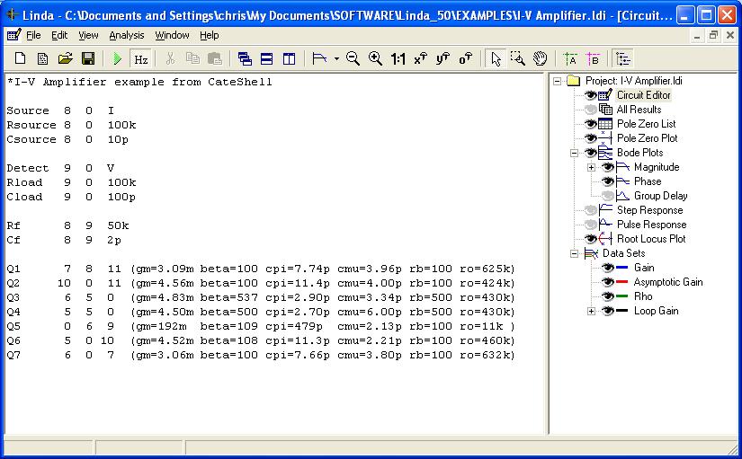
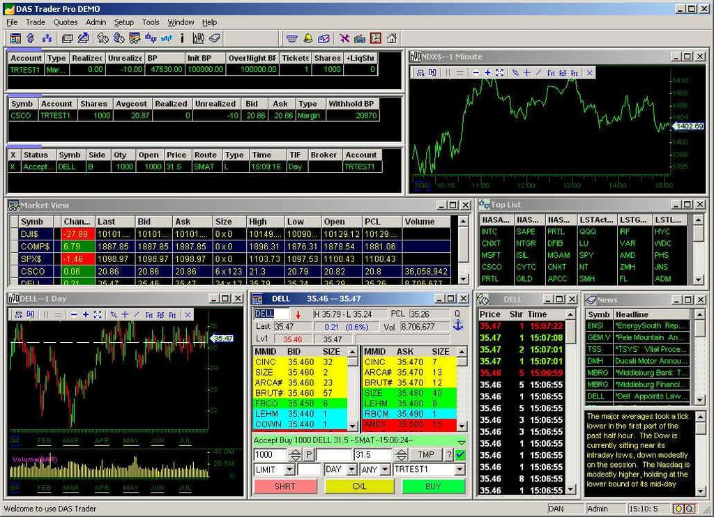
93 Linda 93
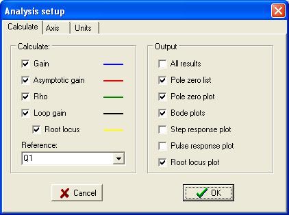
94 Linda simulation 94

95 Linda: root locus 95

96 Linda: bode plot (magnitude) 96
97 Conclusions Idealized circuits can be simulated For verification To find transistor parameters To obtain transistor characteristics To see more complex information (e.g. f-behavior noise) Never a surprising result Linda A To see synthesis parameters (Loopgain, etc.) t 97
5.25Chapter V Problem Set
 5.25Chapter V Problem Set P5.1 Analyze the circuits in Fig. P5.1 and determine the base, collector, and emitter currents of the BJTs as well as the voltages at the base, collector, and emitter terminals.
Analog Integrated Circuit Configurations
 Analog Integrated Circuit Configurations Basic stages: differential pairs, current biasing, mirrors, etc. Approximate analysis for initial design MOSFET and Bipolar circuits Basic Current Bias Sources
BJT Circuits (MCQs of Moderate Complexity)
") BJT Circuits (MCQs of Moderate Complexity) 1. The current ib through base of a silicon npn transistor is 1+0.1 cos (1000πt) ma. At 300K, the rπ in the small signal model of the transistor is i b B C r
BJT Circuits (MCQs of Moderate Complexity) 1. The current ib through base of a silicon npn transistor is 1+0.1 cos (1000πt) ma. At 300K, the rπ in the small signal model of the transistor is i b B C r
Page 1. Telecommunication Electronics ETLCE - A2 06/09/ DDC 1. Politecnico di Torino ICT School. Amplifiers
 Politecnico di Torino ICT School Amplifiers Telecommunication Electronics A2 Transistor amplifiers» Bias point and circuits,» Small signal models» Gain and bandwidth» Limits of linear analysis Op Amp amplifiers
Frequency Response of Common Emitter Amplifier
 Başkent University Department of Electrical and Electronics Engineering EEM 311 Electronics II Experiment 6 Frequency Response of Common Emitter Amplifier Aim: The aim of this experiment is to study the
2. SINGLE STAGE BIPOLAR JUNCTION TRANSISTOR (BJT) AMPLIFIERS
 AMPLIFIERS") 2. SINGLE STAGE BIPOLAR JUNCTION TRANSISTOR (BJT) AMPLIFIERS I. Objectives and Contents The goal of this experiment is to become familiar with BJT as an amplifier and to evaluate the basic configurations
2. SINGLE STAGE BIPOLAR JUNCTION TRANSISTOR (BJT) AMPLIFIERS I. Objectives and Contents The goal of this experiment is to become familiar with BJT as an amplifier and to evaluate the basic configurations
Homework Assignment 12
 Homework Assignment 12 Question 1 Shown the is Bode plot of the magnitude of the gain transfer function of a constant GBP amplifier. By how much will the amplifier delay a sine wave with the following
Physics 160 Lecture 11. R. Johnson May 4, 2015
 Physics 160 Lecture 11 R. Johnson May 4, 2015 Two Solutions to the Miller Effect Putting a matching resistor on the collector of Q 1 would be a big mistake, as it would give no benefit and would produce
ESE319 Introduction to Microelectronics High Frequency BJT Model & Cascode BJT Amplifier
 High Frequency BJT Model & Cascode BJT Amplifier 1 Gain of 10 Amplifier Non-ideal Transistor C in R 1 V CC R 2 v s Gain starts dropping at > 1MHz. Why! Because of internal transistor capacitances that
(a) BJT-OPERATING MODES & CONFIGURATIONS
 BJT-OPERATING MODES & CONFIGURATIONS") (a) BJT-OPERATING MODES & CONFIGURATIONS 1. The leakage current I CBO flows in (a) The emitter, base and collector leads (b) The emitter and base leads. (c) The emitter and collector leads. (d) The base
(a) BJT-OPERATING MODES & CONFIGURATIONS 1. The leakage current I CBO flows in (a) The emitter, base and collector leads (b) The emitter and base leads. (c) The emitter and collector leads. (d) The base
ANALYSIS OF AN NPN COMMON-EMITTER AMPLIFIER
 ANALYSIS OF AN NPN COMMON-EMITTER AMPLIFIER Experiment Performed by: Michael Gonzalez Filip Rege Alexis Rodriguez-Carlson Report Written by: Filip Rege Alexis Rodriguez-Carlson November 28, 2007 Objectives:
AE103 ELECTRONIC DEVICES & CIRCUITS DEC 2014
 Q.2 a. State and explain the Reciprocity Theorem and Thevenins Theorem. a. Reciprocity Theorem: If we consider two loops A and B of network N and if an ideal voltage source E in loop A produces current
The George Washington University School of Engineering and Applied Science Department of Electrical and Computer Engineering ECE 20 - LAB
 The George Washington University School of Engineering and Applied Science Department of Electrical and Computer Engineering ECE 20 - LAB Experiment # 6 (Part I) Bipolar Junction Transistors Common Emitter
INFN Laboratori Nazionali di Legnaro, Marzo 2007 FRONT-END ELECTRONICS PART 2
 INFN Laboratori Nazionali di Legnaro, 6-30 Marzo 007 FRONT-END ELECTRONICS PART Francis ANGHINOLFI Wednesday 8 March 007 Francis.Anghinolfi@cern.ch v1 1 FRONT-END Electronics Part A little bit about signal
Advanced Operational Amplifiers
 IsLab Analog Integrated Circuit Design OPA2-47 Advanced Operational Amplifiers כ Kyungpook National University IsLab Analog Integrated Circuit Design OPA2-1 Advanced Current Mirrors and Opamps Two-stage
By: Dr. Ahmed ElShafee
 Lecture (04) Transistor Bias Circuit 3 BJT Amplifiers 1 By: Dr. Ahmed ElShafee ١ Emitter Feedback Bias If an emitter resistor is added to the base bias circuit in Figure, the result is emitter feedback
UNIT I BIASING OF DISCRETE BJT AND MOSFET PART A
 UNIT I BIASING OF DISCRETE BJT AND MOSFET PART A 1. Why do we choose Q point at the center of the load line? 2. Name the two techniques used in the stability of the q point.explain. 3. Give the expression
DEPARTMENT OF ELECTRONICS AND COMMUNICATION ENGINEERING III SEMESTER EC 6304 ELECTRONIC CIRCUITS I. (Regulations 2013)
") DEPARTMENT OF ELECTRONICS AND COMMUNICATION ENGINEERING III SEMESTER EC 6304 ELECTRONIC CIRCUITS I (Regulations 2013 UNIT-1 Part A 1. What is a Q-point? [N/D 16] The operating point also known as quiescent
DEPARTMENT OF ELECTRONICS AND COMMUNICATION ENGINEERING III SEMESTER EC 6304 ELECTRONIC CIRCUITS I (Regulations 2013 UNIT-1 Part A 1. What is a Q-point? [N/D 16] The operating point also known as quiescent
Improving Amplifier Voltage Gain
 15.1 Multistage ac-coupled Amplifiers 1077 TABLE 15.3 Three-Stage Amplifier Summary HAND ANALYSIS SPICE RESULTS Voltage gain 998 1010 Input signal range 92.7 V Input resistance 1 M 1M Output resistance
TL072 TL072A - TL072B
 A - B LOW NOISE J-FET DUAL OPERATIONAL AMPLIFIERS WIDE COMMON-MODE (UP TO V + CC ) AND DIFFERENTIAL VOLTAGE RANGE LOW INPUT BIAS AND OFFSET CURRENT LOW NOISE e n = 15nV/ Hz (typ) OUTPUT SHORT-CIRCUIT PROTECTION
Lab Experiment #2 Differential Amplifiers. Group Members
 Lab Experiment #2 Differential Amplifiers Group Members Student 1 Student 2 Student 3 Student Name Surname First Name Student ID # Pre-Lab Mark (out of 30) Lab Demo and performance (out of 70) Total Lab
Analog and Telecommunication Electronics
 Politecnico di Torino - ICT School Analog and Telecommunication Electronics A3 BJT Amplifiers»Biasing» Output dynamic range» Small signal analysis» Voltage gain» Frequency response 12/03/2012-1 ATLCE -
I1 19u 5V R11 1MEG IDC Q7 Q2N3904 Q2N3904. Figure 3.1 A scaled down 741 op amp used in this lab
 Lab 3: 74 Op amp Purpose: The purpose of this laboratory is to become familiar with a two stage operational amplifier (op amp). Students will analyze the circuit manually and compare the results with SPICE.
EE4902 C Lab 7
 EE4902 C2007 - Lab 7 MOSFET Differential Amplifier Resistive Load Active Load PURPOSE: The primary purpose of this lab is to measure the performance of the differential amplifier. This is an important
d. Why do circuit designers like to use feedback when they make amplifiers? Give at least two reasons.
 EECS105 Final 5/12/10 Name SID 1 /20 2 /30 3 /20 4 /20 5 /30 6 /40 7 /20 8 /20 Total 1. Give a short answer to each question a. Your friend from Stanford says that he has designed a three-stage high gain
EXPERIMENT NO -9 TRANSITOR COMMON -BASE CONFIGURATION CHARACTERISTICS
 Contents EXPERIMENT NO -9 TRANSITOR COMMON -BASE CONFIGURATION CHARACTERISTICS... 3 EXPERIMENT NO -10. FET CHARACTERISTICS... 8 Experiment # 11 Non-inverting amplifier... 13 Experiment #11(B) Inverting
ECE 3274 Common-Collector (Emitter-Follower) Amplifier Project
 Amplifier Project") ECE 3274 Common-Collector (Emitter-Follower) Amplifier Project 1. Objective This project will show the biasing, gain, frequency response, and impedance properties of a common collector amplifier. 2. Components
ECE 3274 Common-Collector (Emitter-Follower) Amplifier Project 1. Objective This project will show the biasing, gain, frequency response, and impedance properties of a common collector amplifier. 2. Components
UNIVERSITY OF NORTH CAROLINA AT CHARLOTTE Department of Electrical and Computer Engineering
 UNIVERSITY OF NORTH CAROLINA AT CHARLOTTE Department of Electrical and Computer Engineering EXPERIMENT 7 BJT AMPLIFIER CONFIGURATIONS AND INPUT/OUTPUT IMPEDANCE OBJECTIVES The purpose of this experiment
Experiment #8: Designing and Measuring a Common-Collector Amplifier
 SCHOOL OF ENGINEERING AND APPLIED SCIENCE DEPARTMENT OF ELECTRICAL AND COMPUTER ENGINEERING ECE 2115: ENGINEERING ELECTRONICS LABORATORY Experiment #8: Designing and Measuring a Common-Collector Amplifier
ECE4902 C Lab 7
 ECE902 C2012 - Lab MOSFET Differential Amplifier Resistive Load Active Load PURPOSE: The primary purpose of this lab is to measure the performance of the differential amplifier. This is an important topology
QUESTION BANK for Analog Electronics 4EC111 *
 OpenStax-CNX module: m54983 1 QUESTION BANK for Analog Electronics 4EC111 * Bijay_Kumar Sharma This work is produced by OpenStax-CNX and licensed under the Creative Commons Attribution License 4.0 Abstract
UNIT - 1 OPERATIONAL AMPLIFIER FUNDAMENTALS
 UNIT - 1 OPERATIONAL AMPLIFIER FUNDAMENTALS 1.1 Basic operational amplifier circuit- hte basic circuit of an operational amplifier is as shown in above fig. has a differential amplifier input stage and
Chapter 15 Goals. ac-coupled Amplifiers Example of a Three-Stage Amplifier
 Chapter 15 Goals ac-coupled multistage amplifiers including voltage gain, input and output resistances, and small-signal limitations. dc-coupled multistage amplifiers. Darlington configuration and cascode
dc Bias Point Calculations
 dc Bias Point Calculations Find all of the node voltages assuming infinite current gains 9V 9V 10kΩ 9V 100kΩ 1kΩ β = 270kΩ 10kΩ β = 1kΩ 1 dc Bias Point Calculations Find all of the node voltages assuming
4.2.2 Metal Oxide Semiconductor Field Effect Transistor (MOSFET)
") 4.2.2 Metal Oxide Semiconductor Field Effect Transistor (MOSFET) The Metal Oxide Semitonductor Field Effect Transistor (MOSFET) has two modes of operation, the depletion mode, and the enhancement mode.
4.2.2 Metal Oxide Semiconductor Field Effect Transistor (MOSFET) The Metal Oxide Semitonductor Field Effect Transistor (MOSFET) has two modes of operation, the depletion mode, and the enhancement mode.
Two Stage Amplifier Design
 Two Stage Amplifier Design ENGI 242 ELEC 222 HYBRID MODEL PI January 2004 ENGI 242/ELEC 222 2 Multistage Amplifier Design 1 HYBRID MODEL PI PARAMETERS Parasitic Resistances rb = rb b = ohmic resistance
LF147 - LF247 LF347 WIDE BANDWIDTH QUAD J-FET OPERATIONAL AMPLIFIERS
 LF147 - LF247 LF347 WIDE BANDWIDTH QUAD J-FET OPERATIONAL AMPLIFIERS LOW POWER CONSUMPTION WIDE COMMON-MODE (UP TO V + CC ) AND DIFFERENTIAL VOLTAGE RANGE LOW INPUT BIAS AND OFFSET CURRENT OUTPUT SHORT-CIRCUIT
Amplifier Frequency Response, Feedback, Oscillations; Op-Amp Block Diagram and Gain-Bandwidth Product
 Amplifier Frequency Response, Feedback, Oscillations; Op-Amp Block Diagram and Gain-Bandwidth Product Physics116A,12/4/06 Draft Rev. 1, 12/12/06 D. Pellett 2 Negative Feedback and Voltage Amplifier AB
ATLCE - A3 01/03/2016. Analog and Telecommunication Electronics 2016 DDC 1. Politecnico di Torino - ICT School. Lesson A3: BJT Amplifiers
 Politecnico di Torino - ICT School Analog and Telecommunication Electronics A3 BJT Amplifiers»Biasing» Output dynamic range» Small signal analysis» ltage gain» Frequency response AY 2015-16 Biasing Output
Experiment 8 Frequency Response
 Experiment 8 Frequency Response W.T. Yeung, R.A. Cortina, and R.T. Howe UC Berkeley EE 105 Spring 2005 1.0 Objective This lab will introduce the student to frequency response of circuits. The student will
ECE 3274 Common-Emitter Amplifier Project
 ECE 3274 Common-Emitter Amplifier Project 1. Objective The objective of this lab is to design and build the common-emitter amplifier with partial bypass of the emitter resistor to control the AC voltage
Common-Source Amplifiers
 Lab 2: Common-Source Amplifiers Introduction The common-source stage is the most basic amplifier stage encountered in CMOS analog circuits. Because of its very high input impedance, moderate-to-high gain,
Input Stage Concerns. APPLICATION NOTE 656 Design Trade-Offs for Single-Supply Op Amps
 Maxim/Dallas > App Notes > AMPLIFIER AND COMPARATOR CIRCUITS Keywords: single-supply, op amps, amplifiers, design, trade-offs, operational amplifiers Apr 03, 2000 APPLICATION NOTE 656 Design Trade-Offs
PSPICE SIMULATION OF A RESONANT CONVERTER CIRCUIT FOR SWITCHED RELUCTANCE MOTOR DRIVES Souvik Ganguli 1*
 Research Article PSPICE SIMULATION OF A RESONANT CONVERTER CIRCUIT FOR SWITCHED RELUCTANCE MOTOR DRIVES Souvik Ganguli 1* Address for Correspondence 1* Assistant Professor, Department of Electrical & Instrumentation
ECE 442 Solid State Devices & Circuits. 15. Differential Amplifiers
 ECE 442 Solid State Devices & Circuits 15. Differential Amplifiers Jose E. Schutt-Aine Electrical & Computer Engineering University of Illinois jschutt@emlab.uiuc.edu ECE 442 Jose Schutt Aine 1 Background
EE 330 Lecture 20. Operating Points for Amplifier Applications Amplification with Transistor Circuits Small Signal Modelling
 EE 330 Lecture 20 Operating Points for Amplifier Applications Amplification with Transistor Circuits Small Signal Modelling Review from Last Lecture Simplified Multi-Region Model Alternate equivalent model
Linear electronic. Lecture No. 1
 1 Lecture No. 1 2 3 4 5 Lecture No. 2 6 7 8 9 10 11 Lecture No. 3 12 13 14 Lecture No. 4 Example: find Frequency response analysis for the circuit shown in figure below. Where R S =4kR B1 =8kR B2 =4k R
Journal of Engineering Research and Studies
 Research Article PSPICE ANALYSIS OF A VARIABLE DC-LINK VOLTAGE WITH BUCK-BOOST CONVERTER TOPOLOGY FOR SWITCHED RELUCTANCE MOTOR DRIVE Souvik Ganguli * Address for Correspondence * Assistant Professor,
LF153 LF253 - LF353 WIDE BANDWIDTH DUAL J-FET OPERATIONAL AMPLIFIERS
 LF153 LF253 - LF353 WIDE BANDWIDTH DUAL J-FET OPERATIONAL AMPLIFIERS LOW POWER CONSUMPTION WIDE COMMON-MODE (UP TO V + CC ) AND DIFFERENTIAL VOLTAGE RANGE LOW INPUT BIAS AND OFFSET CURRENT OUTPUT SHORT-CIRCUIT
SAMPLE FINAL EXAMINATION FALL TERM
 ENGINEERING SCIENCES 154 ELECTRONIC DEVICES AND CIRCUITS SAMPLE FINAL EXAMINATION FALL TERM 2001-2002 NAME Some Possible Solutions a. Please answer all of the questions in the spaces provided. If you need
Transistor Biasing and Operational amplifier fundamentals. OP-amp Fundamentals and its DC characteristics. BJT biasing schemes
 Lab 1 Transistor Biasing and Operational amplifier fundamentals Experiment 1.1 Experiment 1.2 BJT biasing OP-amp Fundamentals and its DC characteristics BJT biasing schemes 1.1 Objective 1. To sketch potential
E84 Lab 3: Transistor
 E84 Lab 3: Transistor Cherie Ho and Siyi Hu April 18, 2016 Transistor Testing 1. Take screenshots of both the input and output characteristic plots observed on the semiconductor curve tracer with the following
PSPICE ANALYSIS OF A SPLIT DC SUPPLY CONVERTER FOR SWITCHED RELUCTANCE MOTOR DRIVES Souvik Ganguli *
 Research Article PSPICE ANALYSIS OF A SPLIT DC SUPPLY CONVERTER FOR SWITCHED RELUCTANCE MOTOR DRIVES Souvik Ganguli * Address for Correspondence * Assistant Professor, Department of Electrical & Instrumentation
In a cascade configuration, the overall voltage and current gains are given by:
 ECE 3274 Two-Stage Amplifier Project 1. Objective The objective of this lab is to design and build a direct coupled two-stage amplifier, including a common-source gain stage and a common-collector buffer
EE LINEAR INTEGRATED CIRCUITS & APPLICATIONS
 UNITII CHARACTERISTICS OF OPAMP 1. What is an opamp? List its functions. The opamp is a multi terminal device, which internally is quite complex. It is a direct coupled high gain amplifier consisting of
Linear IC s and applications
 Questions and Solutions PART-A Unit-1 INTRODUCTION TO OP-AMPS 1. Explain data acquisition system Jan13 DATA ACQUISITION SYSYTEM BLOCK DIAGRAM: Input stage Intermediate stage Level shifting stage Output
EEE118: Electronic Devices and Circuits
 EEE118: Electronic Devices and Circuits Lecture XIV James E Green Department of Electronic Engineering University of Sheffield j.e.green@sheffield.ac.uk Review Review Considered several transistor switching
Mini Project 3 Multi-Transistor Amplifiers. ELEC 301 University of British Columbia
 Mini Project 3 Multi-Transistor Amplifiers ELEC 30 University of British Columbia 4463854 November 0, 207 Contents 0 Introduction Part : Cascode Amplifier. A - DC Operating Point.......................................
ST.ANNE S COLLEGE OF ENGINEERING AND TECHNOLOGY ANGUCHETTYPALAYAM, PANRUTI Department of Electronics & Communication Engineering OBSERVATION
 ST.ANNE S COLLEGE OF ENGINEERING AND TECHNOLOGY ANGUCHETTYPALAYAM, PANRUTI 67 Department of Electronics & Communication Engineering OBSERVATION EC836 ANALOG AND DIGITAL CIRCUITS LABORATORY STUDENT NAME
Common-source Amplifiers
 Lab 1: Common-source Amplifiers Introduction The common-source amplifier is one of the basic amplifiers in CMOS analog circuits. Because of its very high input impedance, relatively high gain, low noise,
Lab 4. Transistor as an amplifier, part 2
 Lab 4 Transistor as an amplifier, part 2 INTRODUCTION We continue the bi-polar transistor experiments begun in the preceding experiment. In the common emitter amplifier experiment, you will learn techniques
ANALYSIS OF A C-DUMP CONVERTER FOR SWITCHED RELUCTANCE MOTOR DRIVE USING PSPICE Souvik Ganguli 1*
 Research Article ANALYSIS OF A C-DUMP CONVERTER FOR SWITCHED RELUCTANCE MOTOR DRIVE USING PSPICE Souvik Ganguli 1* Address for Correspondence 1* Assistant Professor, Department of Electrical & Instrumentation
Emitter base bias. Collector base bias Active Forward Reverse Saturation forward Forward Cut off Reverse Reverse Inverse Reverse Forward
 SEMICONDUCTOR PHYSICS-2 [Transistor, constructional characteristics, biasing of transistors, transistor configuration, transistor as an amplifier, transistor as a switch, transistor as an oscillator] Transistor
Mini Project 2 Single Transistor Amplifiers. ELEC 301 University of British Columbia
 Mini Project 2 Single Transistor Amplifiers ELEC 301 University of British Columbia 44638154 October 27, 2017 Contents 1 Introduction 1 2 Investigation 1 2.1 Part 1.................................................
NJM324C. Low power quad operational amplifiers
 Low power quad operational amplifiers Features Wide gain bandwidth:.mhz typ. Input common-mode voltage range includes ground Large voltage gain:db typ. Very low supply current per amplifier:ua typ. Low
Electrical, Electronic and Digital Principles (EEDP) Lecture 3. Other BJT Biasing Techniques باسم ممدوح الحلوانى
 Lecture 3. Other BJT Biasing Techniques باسم ممدوح الحلوانى") Electrical, Electronic and Digital Principles (EEDP) Lecture 3 Other BJT Biasing Techniques د. باسم ممدوح الحلوانى Approximate Analysis Voltage-divider Bias Exact Analysis Ri = is the equivalent resistance
Electrical, Electronic and Digital Principles (EEDP) Lecture 3 Other BJT Biasing Techniques د. باسم ممدوح الحلوانى Approximate Analysis Voltage-divider Bias Exact Analysis Ri = is the equivalent resistance
UNIVERSITY OF PENNSYLVANIA EE 206
 UNIVERSITY OF PENNSYLVANIA EE 206 TRANSISTOR BIASING CIRCUITS Introduction: One of the most critical considerations in the design of transistor amplifier stages is the ability of the circuit to maintain
Experiment No. 9 DESIGN AND CHARACTERISTICS OF COMMON BASE AND COMMON COLLECTOR AMPLIFIERS
 Experiment No. 9 DESIGN AND CHARACTERISTICS OF COMMON BASE AND COMMON COLLECTOR AMPLIFIERS 1. Objective: The objective of this experiment is to explore the basic applications of the bipolar junction transistor
Document Name: Electronic Circuits Lab. Facebook: Twitter:
 Document Name: Electronic Circuits Lab www.vidyathiplus.in Facebook: www.facebook.com/vidyarthiplus Twitter: www.twitter.com/vidyarthiplus Copyright 2011-2015 Vidyarthiplus.in (VP Group) Page 1 CIRCUIT
OP07C PRECISION OPERATIONAL AMPLIFIERS
 OP0C PRECISION OPERATIONAL AMPLIFIERS Low Noise No External Components Required Replace Chopper Amplifiers at a Lower Cost Wide Input-Voltage Range...0 to ± V Typ Wide Supply-Voltage Range...± V to ± V
Electronic Troubleshooting
 Electronic Troubleshooting Chapter 3 Bipolar Transistors Most devices still require some individual (discrete) transistors Used to customize operations Interface to external devices Understanding their
Two stage Cascade BJT Amplifier
 Two stage Cascade BJT Amplifier N K Kaphungkui Assistant professor, Electronics & Communication Department, Dibrugarh University, Assam, India ---------------------------------------------------------------------***---------------------------------------------------------------------
ECE 3274 Common-Emitter Amplifier Project
 ECE 3274 Common-Emitter Amplifier Project 1. Objective The objective of this lab is to design and build three variations of the common- emitter amplifier. 2. Components Qty Device 1 2N2222 BJT Transistor
Chapter 5 Transistor Bias Circuits
 Chapter 5 Transistor Bias Circuits Objectives Discuss the concept of dc biasing of a transistor for linear operation Analyze voltage-divider bias, base bias, and collector-feedback bias circuits. Basic
BJT Differential Amplifiers
 Instituto Tecnológico y de Estudios Superiores de Occidente (), OBJECTIVES The general objective of this experiment is to contrast the practical behavior of a real differential pair with its theoretical
LM13600 Dual Operational Transconductance Amplifiers with Linearizing Diodes and Buffers
 LM13600 Dual Operational Transconductance Amplifiers with Linearizing Diodes and Buffers General Description The LM13600 series consists of two current controlled transconductance amplifiers each with
Chapter Two "Bipolar Transistor Circuits"
 Chapter Two "Bipolar Transistor Circuits" 1.TRANSISTOR CONSTRUCTION:- The transistor is a three-layer semiconductor device consisting of either two n- and one p-type layers of material or two p- and one
Design and Simulation of Low Voltage Operational Amplifier
 Design and Simulation of Low Voltage Operational Amplifier Zach Nelson Department of Electrical Engineering, University of Nevada, Las Vegas 4505 S Maryland Pkwy, Las Vegas, NV 89154 United States of America
LM2904AH. Low-power, dual operational amplifier. Related products. Description. Features. See LM2904WH for enhanced ESD performances
 LM2904AH Low-power, dual operational amplifier Datasheet - production data Related products See LM2904WH for enhanced ESD performances Features Frequency compensation implemented internally Large DC voltage
ECE4902 C Lab 5 MOSFET Common Source Amplifier with Active Load Bandwidth of MOSFET Common Source Amplifier: Resistive Load / Active Load
 ECE4902 C2012 - Lab 5 MOSFET Common Source Amplifier with Active Load Bandwidth of MOSFET Common Source Amplifier: Resistive Load / Active Load PURPOSE: The primary purpose of this lab is to measure the
Voltage Biasing Considerations (From the CS atom toward the differential pair atom) Claudio Talarico, Gonzaga University
 Claudio Talarico, Gonzaga University") Voltage Biasing Considerations (From the CS atom toward the differential pair atom) Claudio Talarico, Gonzaga University Voltage Biasing Considerations In addition to bias currents, building a complete
Voltage Biasing Considerations (From the CS atom toward the differential pair atom) Claudio Talarico, Gonzaga University Voltage Biasing Considerations In addition to bias currents, building a complete
GATE SOLVED PAPER - IN
 YEAR 202 ONE MARK Q. The i-v characteristics of the diode in the circuit given below are : v -. A v 0.7 V i 500 07 $ = * 0 A, v < 0.7 V The current in the circuit is (A) 0 ma (C) 6.67 ma (B) 9.3 ma (D)
Chapter 6. BJT Amplifiers
 Basic Electronic Devices and Circuits EE 111 Electrical Engineering Majmaah University 2 nd Semester 1432/1433 H Chapter 6 BJT Amplifiers 1 Introduction The things you learned about biasing a transistor
BJT Amplifier. Superposition principle (linear amplifier)
") BJT Amplifier Two types analysis DC analysis Applied DC voltage source AC analysis Time varying signal source Superposition principle (linear amplifier) The response of a linear amplifier circuit excited
BJT Amplifier Two types analysis DC analysis Applied DC voltage source AC analysis Time varying signal source Superposition principle (linear amplifier) The response of a linear amplifier circuit excited
Homework Assignment 01
 Homework Assignment 01 In this homework set students review some basic circuit analysis techniques, as well as review how to analyze ideal op-amp circuits. Numerical answers must be supplied using engineering
RT2904WH. RobuST low-power dual operational amplifier. Applications. Features. Description
 RobuST low-power dual operational amplifier Datasheet - production data Features D SO8 (plastic micropackage) Pin connections (top view) Frequency compensation implemented internally Large DC voltage gain:
Experiment 8&9 BJT AMPLIFIER
 Experiment 8&9 BJT AMPLIFIER 1 BJT AS AMPLIFIER 1. Objectiv e: 1- To demonstrate the operation and characteristics of small signals common emitter amplifiers. 2- What do we mean by a linear amplifier and
Boosting output in high-voltage op-amps with a current buffer
 Boosting output in high-voltage op-amps with a current buffer Author: Joe Kyriakakis, Apex Microtechnology Date: 02/18/2014 Categories: Current, Design Tools, High Voltage, MOSFETs & Power MOSFETs, Op
LF442 Dual Low Power JFET Input Operational Amplifier
 LF442 Dual Low Power JFET Input Operational Amplifier General Description The LF442 dual low power operational amplifiers provide many of the same AC characteristics as the industry standard LM1458 while
7. Bipolar Junction Transistor
 41 7. Bipolar Junction Transistor 7.1. Objectives - To experimentally examine the principles of operation of bipolar junction transistor (BJT); - To measure basic characteristics of n-p-n silicon transistor
Designing an Audio Amplifier Using a Class B Push-Pull Output Stage
 Designing an Audio Amplifier Using a Class B Push-Pull Output Stage Angel Zhang Electrical Engineering The Cooper Union for the Advancement of Science and Art Manhattan, NY Jeffrey Shih Electrical Engineering
Federal Urdu University of Arts, Science & Technology Islamabad Pakistan THIRD SEMESTER ELECTRONICS - II BASIC ELECTRICAL & ELECTRONICS LAB
 THIRD SEMESTER ELECTRONICS - II BASIC ELECTRICAL & ELECTRONICS LAB DEPARTMENT OF ELECTRICAL ENGINEERING Prepared By: Checked By: Approved By: Engr. Saqib Riaz Engr. M.Nasim Khan Dr.Noman Jafri Lecturer
Linear Regulators: Theory of Operation and Compensation
 Linear Regulators: Theory of Operation and Compensation Introduction The explosive proliferation of battery powered equipment in the past decade has created unique requirements for a voltage regulator
BIPOLAR JUNCTION TRANSISTORS (BJTs) Dr Derek Molloy, DCU
 Dr Derek Molloy, DCU") IPOLAR JUNCTION TRANSISTORS (JTs) Dr Derek Molloy, DCU What are JTs? Two PN junctions joined together is a JT Simply known as a transistor! ipolar? Current carried by electrons and holes Will see FETs
IPOLAR JUNCTION TRANSISTORS (JTs) Dr Derek Molloy, DCU What are JTs? Two PN junctions joined together is a JT Simply known as a transistor! ipolar? Current carried by electrons and holes Will see FETs
Lecture 21: Voltage/Current Buffer Freq Response
 Lecture 21: Voltage/Current Buffer Freq Response Prof. Niknejad Lecture Outline Last Time: Frequency Response of Voltage Buffer Frequency Response of Current Buffer Current Mirrors Biasing Schemes Detailed
Low power quad operational amplifiers
 Low power quad operational amplifiers Features Wide gain bandwidth:.mhz typ. Input common-mode voltage range includes ground Large voltage gain:db typ. Very low supply current per amplifier:ua typ. Low
A Compact Folded-cascode Operational Amplifier with Class-AB Output Stage
 A Compact Folded-cascode Operational Amplifier with Class-AB Output Stage EEE 523 Advanced Analog Integrated Circuits Project Report Fuding Ge You are an engineer who is assigned the project to design
Laboratory Experiment 8 EE348L. Spring 2005
 Laboratory Experiment 8 EE348L Spring 2005 B. Madhavan Spring 2005 B. Madhavan Page 1 of 1 EE348L, Spring 2005 B. Madhavan - 2 of 2- EE348L, Spring 2005 Table of Contents 8 Experiment #8: Introduction
Analog Circuits and Systems
 Analog Circuits and Systems Prof. K Radhakrishna Rao Lecture 10: Electronic Devices for Analog Circuits 1 Multipliers Multipliers provide multiplication of two input voltages or currents Multipliers can
Revised: January 26,
 ECE 3274 Active Load Common Emitter Amplifier Project 1. Objective This project will show how the use of an active load in a common emitter amplifier can affect the gain open loop gain. 2. Components Qty