CL Range Logic relays. Logic relays. Logic relays. Phone: Fax: Web:
|
|
|
- Bathsheba Sanders
- 5 years ago
- Views:
Transcription
1 CL Range
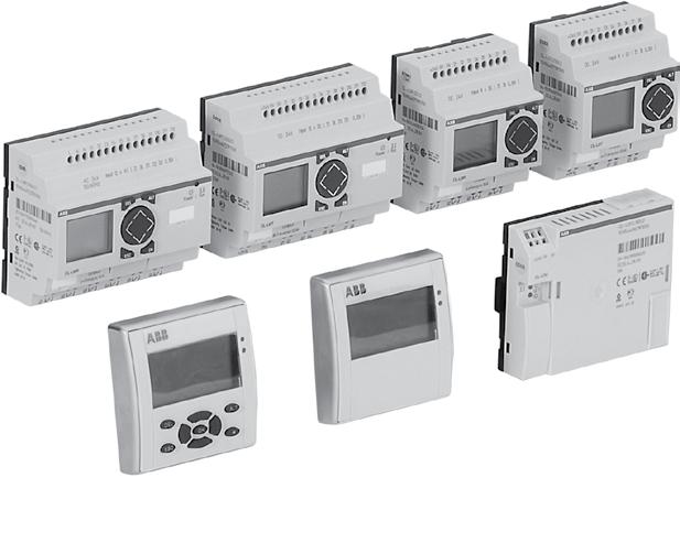
2 CL Range System overview Concept CL range logic relays are suitable for small and medium-sized control tasks and are able to substitute logic wiring in a quick and simple manner. They can be used for applications in control as well as for timing functions, e. g. in buildings, lighting systems, air-conditioning systems, general control functions, in small machines and systems or as stand-alone control module for small applications. Steps to the application of CL range CL range can be used easily, rapidly and comfortably without any timeconsuming planning and programming. The user can discover the advantages and the benefit of these logic relays in no time at all. CL range provides for the control statements according to a simple circuit diagram. Setup, storage, simulation and documentation are performed using the compact and user-friendly CL-SOFT software (CL-LAS.PS002). Logic links instead of wiring S1 K1 S4 S5 S T1 T1 K1 K2 T1 Documentation (download from the internet) Logic relay manual 1SVC M0100 Remote display manual 1SVC M2100 Display system manual 1SVC M1100 Software characteristics (CL-SOFT) display on a PC monitor according to IEC, ANSI different languages to choose from easy installation on all Microsoft Windows TM operating systems Technical Data overview 8 or 12 digital inputs 4 or digital relay outputs optionally with 4 or 8 transistor outputs 128 rungs 3 contacts as n/o or n/c contacts in series plus 1 coil per rung optionally with 2 or 4 analog inputs (not V AC version) power flow display for checking the circuit diagram (devices with display) expansions for local or remote level enclosure color RAL 7035 DIN rail mounting Display system usable as compact HMI logic relay fully graphic, backlit display module 12 digital inputs 4 digital relay outputs optionally with 4 transistor outputs 25 rungs 4 contacts as n/o or n/c contacts in series plus 1 coil per rung optionally with 4 analog inputs (not V AC version) networking-compatible via CL-NET front panel mounting expansion for local Remote display Remote display up to a distance of 5 m Illustration of text and status displays Remote adjustment via keypad Front panel mounting Software 1 timing relays :59 h 1 counting relays for up-, down counting 8 weekly timer, 8 annual timers 1 analog value comparators 1 freely editable display texts 32 markers or auxiliary relays
3 System overview CL Range Stand alone 2 2 Power Expandable Power Display system R Compact HMI logic relay CL-NET b 5 8a 9 1a, 8b 5 1b, 8b 8b 8a 9 1a Logic relay CL-LS.. 1b Expandable logic relay CL-LM.. 2 Power supply CP-D... 3 I/O expansion CL-LER.., CL-LET.. for logic relays CL-LM.. 4 Coupler unit CL-LEC.. for remote expansion of logic relays CL-LM.. 5 Memory module CL-LAS.MD003 for logic relays CL-LS.., CL-LM.. Connecting cable CL-LAS.TK001, CL-LAS.TK002 to connect PC 7 CL-LINK plug CL-LAS.TK011 to connect expansion to logic relays CL-LM.. 8a Remote display connection module CL-LDC.S.. 8b Connecting cable CL-LAD.TK007 to connect a remote displays to a logic relay 9 Display module CL-LDD.. Expansion of logic relays* Display module CL-LDD.. 2 Display base module CL-LDC.LN.. 3 Display I/O module CL-LDR.., CL-LDT.. 4 Termination resistor CL-LAD.TK009 5 I/O expansion CL-LER.., CL-LET.. Coupler unit CL-LEC.. for remote expansion 7 Memory module CL-LAD.MD004 for display base module 8 Connecting cable CL-LAD.TK002, CL-LAD.TK003, CL-LAD.TK004 9 Connecting cable CL-LAD.TK001, CL-LAD.TK011 to connect PC 10 CL-LINK plug CL-LAS.TK011 for expansion of logic relays CL-LM.. K e.g. door of switchgear cabinet Stand alone with I/O module Display CL-LDD.. 2 Remote display connection module CL-LDC.S.. incl. connecting cable 3 Display base module CL-LDC.L b Communication via CL-NET CL-NET a 1 Logic relay CL-LM.. 2 I/O expansion CL-LER.., CL-LET.. 2allocal expansion 2blremote expansion 3 Coupler unit CL-LEC.. for remote expansion of logic relays CL-LM.. 4 CL-LINK plug CL-LAS.TK011 for expansion of logic relays CL-LM.. 5 up to 30 m * max. 1 expansion per logic relay Display CL-LDD.. 2 Display base module CL-LDC.LN.. for CL-NET 3 Display I/O module CL-LDR.., CL-LDT.. 4 Connecting cable CL-LAD.TK002, CL-LAD.TK003, CL-LAD.TK004 5 Termination resistor CL-LAD.TK009
4 CL Range Approvals and marks J existing j pending Expansions Display system Accessories Approvals CL-LSR CL-LST CL-LMR CL-LMT CL-LER CL-LET CL-LEC CL-LDD CL-LDC CL-LDR CL-LDT CL-LAS CL-LAD B UL J J J J J J J J J J J J 1) J 2) F CAN/CSA C22.2 No.14 J J J J J J J J J J J J 1) J 2) F CAN/CSA C22.2 No.213 (hazardous locations) J J J J J J J J J J J J 1) J 2) C GL J J J J J J 3) J 4) J D GOST J J J J J J J J J J J J J P Lloyds Register J J J J J J 3) J 4) J Marks a CE J J J J J J J J J J J J J b C-Tick k k k k k k k k k k k k k 1) not for: CL-LAS-PS002, CL-LAS.TD001, CL-LAS.FD001, CL-LAS.TK002, CL-LAS.TK011 2) not for: CL-LAD.TK00, CL-LAD.TK011, CL-LAD.FD002 3) not for: CL-LDC.SDC2, CL-LDC.SAC2, CL-LDC.LAC2, CL-LDC.LNAC2 4) not for: CL-LDR.1AC2

 kg (lb) 0.20 (0.")
 - 24 V DC 100-240 V DC Graphic display 132 x 4 pixel, with keypad Module to displace the display from the logic relay, incl. connecting cable CL-LAD.TK007, 5m, lenght adaptable CL-LDD.")
5 Ordering details Stand alone logic relays CL Range stand alone CL-LSR Rated operational voltage 24 V AC V AC 12 V DC 24 V DC 24 V DC Display + Keypad J Timer Input / Output Reference code Catalog number J CL-LSR.C12AC1 1SVR440712R0300 J CL-LSR.CX12AC1 1SVR440712R0200 J CL-LSR.12AC2 1SVR440713R0100 J J CL-LSR.C12AC2 1SVR440713R0300 J J J 8 inputs / 4 relay outputs CL-LSR.CX12AC2 CL-LSR.C12DC1 1SVR440713R0200 1SVR440710R0300 J CL-LSR.CX12DC1 1SVR440710R0200 J CL-LSR.12DC2 1SVR440711R0100 J CL-LSR.C12DC2 1SVR440711R0300 J CL-LSR.CX12DC2 1SVR440711R0200 J J 8 inputs / CL-LST.C12DC2 1SVR440711R transistor J outputs CL-LST.CX12DC2 1SVR440711R1200 Weight (1 pce) kg (lb) 0.20 (0.44) CL-LST Display modules Rated operational voltage Description Reference code Catalog number Weight (1 pce) kg (lb) - Graphic display 132 x 4 pixel CL-LDD.XK 1SVR440839R (0.30) - 24 V DC V DC Graphic display 132 x 4 pixel, with keypad Module to displace the display from the logic relay, incl. connecting cable CL-LAD.TK007, 5m, lenght adaptable CL-LDD.K 1SVR440839R (0.29) CL-LDC.SDC2 1SVR440841R (0.3) CL-LDC.SAC2 1SVR440843R (0.3) CL-LDD.K CL-LDC.S..


 100-240 V AC CL-LER.18AC2 1SVR440723R0000 0.2 (0.57) 12 inputs, relay outputs 24 V DC CL-LER.18DC2 1SVR440721R0000 0.22 (0.49) 24 V DC 12 inputs, 8 transistor outputs CL-LET.")
6 CL Range Ordering details Expandable logic relays expandable Rated operational voltage Display + Keypad Timer Input / Output Reference code Catalog number Weight (1 pce) kg (lb) CL-LMR 24 V AC V AC 12 V DC 24 V DC 24 V DC J J CL-LMR.C18AC1 1SVR440722R0300 J CL-LMR.CX18AC1 1SVR440722R0200 J J CL-LMR.C18AC2 1SVR440723R0300 J 12 inputs / CL-LMR.CX18AC2 1SVR440723R0200 relay J J outputs CL-LMR.C18DC1 1SVR440720R0300 J CL-LMR.CX18DC1 1SVR440720R0200 J J CL-LMR.C18DC2 1SVR440721R0300 J CL-LMR.CX18DC2 1SVR440721R0200 J J 12 inputs, CL-LMT.C20DC2 1SVR440721R transistor J outputs CL-LMT.CX20DC2 1SVR440721R (0.79) 0.3 (0.79) Expansions Rated operational voltage Description Reference code Catalog number Weight (1 pce) kg (lb) CL-LER - 2 relay outputs CL-LER.2O 1SVR440709R (0.15) V AC CL-LER.18AC2 1SVR440723R (0.57) 12 inputs, relay outputs 24 V DC CL-LER.18DC2 1SVR440721R (0.49) 24 V DC 12 inputs, 8 transistor outputs CL-LET.20DC2 1SVR440721R (0.4) - Coupler unit for remote expansion with a distance of up to 30 m CL-LEC.CI000 1SVR440709R (0.15) CL-LEC
 Memory module for logic relays Memory size: 32 kb Cable with serial interface to connect PC and logic relay.")

 for connection of logic relay to expansion Primary switch mode power supplies, Rated input voltage: 100-240 V AC Rated output voltage/current: 24 V DC / 0.")
7 Ordering details CL Range CL-LA... Description Reference code Catalog number Weight (1 pce) kg (lb) Software for programming and control of CL range devices. Installation CD-ROM for Microsoft Windows TM. CL-LAS.PS002 1SVR440799R (0.21) Memory module for logic relays Memory size: 32 kb Cable with serial interface to connect PC and logic relay. Length: 2 m CL-LAS.MD003 1SVR440799R (0.04 CL-LAS.TK001 1SVR440799R (0.22) Cable with USB interface to connect PC and logic relay CL-LAS.TK002 1SVR440799R (0.13) CL-LAS.PS002 CL-LAS.TK001 Cable for point-to-point connection of remote-display connection module and logic relay, length adaptable Fixing brackets for screw mounting of logic relay, expansion, display base module Spare plug (CL-LINK) for connection of logic relay to expansion Primary switch mode power supplies, Rated input voltage: V AC Rated output voltage/current: 24 V DC / 0.42 A Primary switch mode power supplies, Rated input voltage: V AC Rated output voltage/current: 24 V DC / 1.3 A CL-LAD.TK007 1SVR440899R (0.44) CL-LAS.FD001 1SVR440799R (0.01) CL-LAS.TK011 1SVR440799R (0.22) CP-D 24/0.42 1) 1SVR427041R (0.13) CP-D 24/1.3 2) 1SVR427043R (0.41) 1) replaces CL-LAS.SD001, technical data see chapter Primary switch mode power supplies 2) replaces CL-LAS.SD002, technical data see chapter Primary switch mode power supplies CL-LAS.MD003
 kg (lb) - Display module Graphic display 132 x 4 pixel CL-LDD.XK 1SVR440839R4500 0.14 (0.")
 24 V DC Display base module CL-LDC.LNDC2 1SVR440821R1000 CPU / power supply, networking-compatible (CL-NET) CL-LDC.LNAC2 1SVR440823R1000 100-240 V AC 0.17 (0.")
 24 V DC Display I/O module 12 inputs, 4 relay outputs, CL-LDR.17DC2 1SVR440851R2000 0.17 (0.38) 1 analog output 24 V DC Display I/O module 12 inputs, 4 transistor outputs CL-LDT.")
8 CL Range Ordering details Display systems CL-LDD.K Display systems Rated operational voltage Description Reference code Catalog number Weight (1 pce) kg (lb) - Display module Graphic display 132 x 4 pixel CL-LDD.XK 1SVR440839R (0.30) - Display module Graphic display 132 x 4 pixel, with keypad CL-LDD.K 1SVR440839R (0.29) 24 V DC Display base module CL-LDC.LDC2 1SVR440821R V AC CPU / power supply CL-LDC.LAC2 1SVR440823R (0.3) 24 V DC Display base module CL-LDC.LNDC2 1SVR440821R1000 CPU / power supply, networking-compatible (CL-NET) CL-LDC.LNAC2 1SVR440823R V AC 0.17 (0.38) V AC Display I/O module CL-LDR.1AC2 1SVR440853R V DC 12 inputs, 4 relay outputs CL-LDR.1DC2 1SVR440851R (0.38) 24 V DC Display I/O module 12 inputs, 4 relay outputs, CL-LDR.17DC2 1SVR440851R (0.38) 1 analog output 24 V DC Display I/O module 12 inputs, 4 transistor outputs CL-LDT.1DC2 1SVR440851R (0.30) 24 V DC Display I/O module 12 inputs, 4 transistor outputs, 1 analog output CL-LDT.17DC2 1SVR440851R (0.30) CL-LDC.LN.. CL-LAD... CL-LAD.MD004 Description Memory module for display base modules Memory size: 25 kb Cable with serial interface to connect PC and display base module Cable with USB interface to connect PC and display base module Network cable (CL-NET) to connect 2 display base modules Length: 0.3 m Network cable (CL-NET) to connect 2 display base modules Length: 0.8 m Network cable (CL-NET) to connect 2 display base modules Length: 1.5 m Cable for point-to-point connection of remote display connection modules and display base module, length adaptable, Length: 5 m Cable for point-to-point connection of 2 display base modules, length adaptable. Length: 5 m Reference code Catalog number Weight (1 pce) kg (lb) CL-LAD.MD004 1SVR440899R (0.03) CL-LAD.TK001 1SVR440899R (0.23) CL-LAD.TK011 1SVR440899R700 CL-LAD.TK002 1SVR440899R (0.12) CL-LAD.TK003 1SVR440899R (0.14) CL-LAD.TK004 1SVR440899R (0.18) CL-LAD.TK005 1SVR440899R (0.44) CL-LAD.TK00 1SVR440899R (0.2) Termination resistor, content: 2 pieces CL-LAD.TK009 1SVR440899R (0.02) Protective cover, transparent, for harsh environmental conditions and application in the food industry CL-LAD.FD001 1SVR440899R (0.07) CL-LAD.TK001 Protective cover, transparent and sealable CL-LAD.FD011 1SVR440899R (0.07) Assembly tool for mounting of display modules CL-LAD.FD002 1SVR440899R3000 CL-LAD.TK002
9 CL Range CL-LSR...12DC2 CL-LSR.C...12DC1 CL-LST.C...12DC2 CL-LSR.C...12AC1 CL-LSR...12AC2 Input circuit - supply circuit Rated operational voltage U e 12 V DC 24 V DC 24 V AC V AC Rated operational voltage tolerance % % % Operational voltage range V DC V DC V AC V AC Rated frequency 0 Hz 50/0 Hz Rated frequency tolerance - ±5 % Residual ripple m 5 % - Input current at 12 V DC typ. 140 ma at 24 V DC - typ. 80 ma - - at 24 V AC - - typ. 200 ma - at 115/120 V AC (0 Hz) typ. 40 ma at 230/240 V AC (50 Hz) typ. 20 ma Power failure buffering (IEC/EN ) 10 ms 20 ms Power dissipation at 12 V DC typ. 2 W at 24 V DC - typ. 2 W - - at 24 V AC - - typ 5 VA - at 115/120 V AC typ. 5 VA at 230/240 V AC typ. 5 VA CL-LMR.C...18DC2 CL-LMR.C...18DC1 CL-LMT.C...20DC2 CL-LMR.C...18AC1 CL-LMR.C...18AC2 Input circuit - supply circuit Rated operational voltage U e 12 V DC 24 V DC 24 V AC V AC Rated operational voltage tolerance % % % Operational voltage range V DC V DC V AC V AC Rated frequency 0 Hz 50/0 Hz Rated frequency tolerance - ±5 % Residual ripple m 5 % - Input current at 12 V DC typ. 200 ma at 24 V DC - typ. 140 ma - - at 24 V AC - - typ. 300 ma - at 115/120 V AC (0 Hz) typ. 70 ma at 230/240 V AC (50 Hz) typ. 35 ma Power failure buffering (IEC/EN ) 10 ms 20 ms Power dissipation at 12 V DC typ. 3.5 W at 24 V DC - typ. 3.5 W - - at 24 V AC - - typ. 7 VA - at 115/120 V AC typ. 10 VA at 230/240 V AC typ. 10 VA CL-LER.18DC2 CL-LET.20DC2 CL-LER.18AC2 Input circuit - supply circuit Rated operational voltage U e 24 V DC V AC Rated operational voltage tolerance % % Operational voltage range V DC V AC Rated frequency 0 Hz 50/0 Hz Rated frequency tolerance - ±5 % Residual ripple m 5 % - Input current at 24 V DC typ. 140 ma - at 115/120 V AC (0 Hz) - typ. 70 ma at 230/240 V AC (50 Hz) - typ. 35 ma Power failure buffering (IEC/EN ) 10 ms 20 ms Power dissipation at 24 V DC typ. 3.4 W - at 115/120 V AC - typ. 10 VA at 230/240 V AC - typ. 10 VA
10 CL Range CL-LSR...12DC2 CL-LSR.C...12DC1 CL-LSR.C...12AC1 CL-LSR.C...12AC2 CL-LST.C...12DC2 Input circuit - Digital inputs 12 V DC 24 V DC 24 V AC 115 / 230 V AC Number 8 Inputs can be used as analog inputs 2 (I7, I8) - Indication of operational states LCD-Display (if existing) Electrical isolation from voltage supply no between digital inputs from the outputs Rated operational 12 V DC 24 V DC 24 V AC voltage U e U e on 0 signal 4 V DC (I1-I8) < 5 V DC (I1-I8) 0- V AC (sinusoidal) 0-40 V AC (sinusoidal) U e on 1 signal 8 V DC (I1-I8) > 15 V DC (I1-I), > 8 V DC (I7, I8) no > 9.5 V DC, 14-2,4 V AC (sinusoidal) (I1-I), > 7 V AC (sinusoidal) (I7,I8) Rated frequency Hz Input current on 1 signal Time delay from 0 to 1 Time delay from 1 to ma (at 12 V DC, I1-I), 1.1 ma (at 12 V DC, I7, I8) 3.3 ma (at 24 V DC, I-I7), 2.2 ma (at 24 V DC, I7, I8) 4 ma (at 24 V AC, 50 Hz, I1-I), 2 ma (at 24 V AC, 50 Hz, I7,I8), 2 ma (at 24 V DC, I7, I8) V AC (sinusoidal) x0.25 ma (at 115 V AC, 0 Hz, I1-I), x0.5 ma (at 230 V AC, 50 Hz, I1-I) 2x4 ma (at 115 V AC, 0 Hz, I7, I8), 2x ma (at 230 V AC, 50 Hz, I7, I8) debounce ON 20 ms 80 ms (at 50 Hz), 2 /3 ms (at 0 Hz) debounce OFF typ. 0.3 ms (I1-I), typ ms (I7, I8) typ. 0,25 ms (I1-I8) 20 ms (at 50 Hz), 1 2 /3 ms (at 0 Hz) debounce ON 80 ms (at 50 Hz, I1-I), 20 ms 80 ms (at 50 Hz, 2 /3 ms (at 0 Hz, I1-I) 2 /3 ms (at 0 Hz) 10 ms (at 50 Hz, I7, I8), 150 ms (at 0 Hz, I7, I8) debounce OFF typ. 0.3 ms (I1-I), typ ms (I7, I8) - 20 ms (at 50 Hz), 1 2 /3 ms (at 0 Hz) 20 ms (at 50 Hz, I1-I), 1 2 /3 ms (at 0 Hz, I1-I) 100 ms (at 50 Hz, I7. I8), 100 ms (at 0 Hz, I7, I8) Cable length (unshielded) 100 m - - Maximum cable length per input - 40 m 40 m (I1-I), 100 m (I7, I8) Frequency counter Number 2 (I3, I4) - - counting frequency < 1 khz - - pulse shape square-wave - - pulse / pause ratio 1:1 - - Rapid counter inputs Number 2 (I1, I2) - - counting frequency < 1 khz - - pulse shape square-wave - - pulse / pause ratio 1:1 - - Cable length (shielded) < 20 m - - Input circuit - Analog inputs Number 2 (I7, I8) - Electrical isolation from voltage supply no - from the digital inputs no - from the outputs - from PC interface, memory module, CL-NET, CL-LINK no - Input type DC voltage - Signal range 0-10 V DC - Resolution analog 0.01 V - digital 0.01 V; 10 Bit (value ) - Input impedance 11.2 kq - Accuracy of the two CL devices ±3 % - actual value within one device ±2 %, ±0.12 V - Conversion time Input delay ON 20 ms - analog/digital Input delay OFF each cycle - Input current < 1 ma - Cable length (shielded) < 30 m -
11 CL Range CL-LMR.C...18DC2 CL-LMR.C...18DC1 CL-LMT.C...20DC2 CL-LMR.C...18AC1 CL-LMR.C...18AC2 Input circuit - Digital inputs 12 V DC 24 V DC 24 V AC 115 / 230 V AC Number 12 Inputs can be used as analog inputs 4 (I7, I8, I11, I12) - Indication of operational states LCD-Display (if existing) Electrical isolation from voltage supply no between digital inputs no from the outputs from PC interface, memory module, CL-NET, CL-LINK no Rated operational 12 V DC 24 V DC 24 V AC voltage U e U e on 0 signal 4 V DC (I1-I12) < 5 V DC (I1-I12, R1-R12) 0- V AC (sinusoidal) 0-40 V AC (sinusoidal) U e on 1 signal > 9.5 V DC, V AC 8 V DC (I1-I12) > 15 V DC (I1-I, I9, I10) (sinusoidal) (I1-I, I9, I10) V AC > 8 V DC (I7, I8, I11, I12) > 7 V AC (sinusoidal) (sinusoidal) (I7,I8; I11, I12) Rated frequency Hz Input current on 1 signal Time delay from 0 to 1 Time delay from 1 to 0 Cable length (unshielded) 3.3 ma (at 12 V DC, I1-I, I9-I12), 1.1 ma (at 12 V DC, I7, I8) 3.3 ma (at 24 V DC, I1-I, I9, I10), 2.2 ma (at 24 V DC, I7, I8, I11, I12) 4 ma (at 24 V AC, 50 Hz, I1-I, I9, I10), 2 ma (at 24 V AC, 50 Hz, I7, I8, I11, I12), 2 ma (at 24 V DC, I7, I8, I11, I12) x0.25 ma (at 115 V AC, 0 Hz, I1-I), x0.5 ma (at 230 V AC, 50 Hz, I1-I) 2x4 ma (at 115 V AC, 0 Hz, I7, I8), 2x ma (at 230 V AC, 50 Hz, I7, I8), 4x0.25 ma (at 115 V AC, 0 Hz, I9-I12), 4x0.5 ma (at 230 V AC, 50 Hz, I9-I12) debounce ON 20 ms 80 ms (at 50 Hz), 2 /3 ms (at 0 Hz) debounce OFF typ. 0.3 ms (I1-I, I9, I10), typ ms (I7, I8, I11, I12) typ ms 20 ms (at 50 Hz), 1 2 /3 ms (at 0 Hz) debounce ON 20 ms 80 ms (at 50 Hz), 2 /3 ms (at 0 Hz) debounce OFF typ. 0.4 ms (I1-I, I9, I10), typ ms (I7, I8, I11, I12) - 20 ms (at 50 Hz), 1 2 /3 ms (at 0 Hz) 100 m Maximum cable length per input max. 40 m, typ. 40 m (I9, I10) typ. 40 m (I1-I, I9-I12), typ. 100 m (I7, I8) Frequency counter number 2 (I3, I4) - - counting frequency < 1 khz - - pulse shape square-wave - - pulse / pause ratio 1:1 - - Rapid counter inputs number 2 (I1, I2) - - counting frequency < 1 khz - - pulse shape square-wave - - pulse / pause ratio 1:1 - - Cable length (shielded) < 20 m - - Input circuit - Analog inputs Number 4 (I7, I8, I11, I12) - Electrical isolation from voltage supply no - from the digital inputs no - from the outputs - from PC interface, memory module, CL-NET, CL-LINK no - Input type DC voltage - Signal range 0-10 V DC - Resolution analog 0.01 V - digital 0.01 V; 10 Bit (value ) - Input impedance 11.2 kq - Accuracy of the actual value Conversion time analog/digital two CL devices ±3 % - within one device ±2 %, ±0.12 V - Input delay ON 20 ms - Input delay OFF each cycle - Input current < 1 ma - Cable length (shielded) < 30 m -
12 CL Range CL-LER.18DC2 CL-LET.20DC2 CL-LER.18AC2 Input circuit - Digital inputs 24 V DC 115 / 230 V AC Number 12 Inputs can be used as analog inputs - Indication of operational states - Electrical isolation from voltage supply no between digital inputs no from the outputs from PC interface, memory module, CL-NET, CL-LINK no Rated operational 24 V DC voltage U e U e on 0 signal < 5 V DC (I1-I12, R1-R12) 0-40 V AC (sinusoidal) U e on 1 signal V AC (sinusoidal) Rated frequency Hz Input current on 1 signal Time delay from 0 to 1 Time delay from 1 to 0 debounce ON debounce OFF debounce ON debounce OFF 3.3 ma (at 24 V DC, R1-R12) 20 ms typ ms (R1-R12) 20 ms - 12x0.25 ma (at 115 V AC, 0 Hz, R1-R12), 12x0.5 ma (at 230 V AC, 50 Hz, R1-R12) 80 ms (at 50 Hz, I1-I12, R1-R12), 2 /3 ms (at 0 Hz, I1-I12, R1-R12) 20 ms (at 50 Hz, I1-I12, R1-R12), 1 2 /3 ms (at 0 Hz, I1-I12, R1-R12) 80 ms (at 50 Hz, I1-I12, R1-R12), 2 /3 ms (at 0 Hz, I1-I12, R1-R12) 20 ms (at 50 Hz, I1-I12, R1-R12), 1 2 /3 ms (at 0 Hz, I1-I12, R1-R12) Cable length (unshielded) 100 m - Maximum cable length per input typ. 40 m (I1-I, I9-I12, R1-R12), - typ. 100 m (I7, I8)
13 CL Range Output circuit - Relay outputs CL-LSR... CL-LMR... CL-LER... Number 4 2 Outputs in groups of 1 2 Parallel switching of outputs to increase capacity Fusing of the output relay not permissible circuit-breaker B1 or fuse 8 A (slow-acting) Electrical isolation from voltage supply Mechanical lifetime from the inputs from PC interface, memory module, CL-NET, CL-LINK protective separation basic isolation no 300 V AC 00 V AC 10x10 switching cycles Rung conventional thermal current (10 A UL) 8 A recommended for load 12 V AC/DC short-circuit proof cos j = 1; characteristic B1 at 00 A short-circuit proof cos j = 0.5 up to 0.7; characteristic B1 at 900 A Rated impulse withstand voltage U imp contact-coil > 500 ma Rated operational voltage U e 250 V AC Rated insulation voltage U i 250 V AC Protective separation (EN 50178) between coil and contact 300 V AC between two contacts 1 A 1 A kv 300V AC Making capacity AC15, 250 V AC, 3 A (00 ops./h) switching cycles DC13, L/R m 150 ms, 24 V DC, 1 A (500 ops./h) switching cycles Breaking capacity AC15, 250 V AC, 3 A (00 ops./h) switching cycles DC13, L/R m 150 ms, 24 V DC, 1 A (500 ops./h) switching cycles Incandesent lamp load 1000 W at 230/240 V AC switching cycles Fluorescent lamp load 500 W at 115/120 V AC switching cycles 10 x 58 W at 230/240 V AC with electrical control gear 10 x 58 W at 230/240 V AC uncompensated 1 x 58 W at 230/240 V AC conventional compensated switching cycles switching cycles switching cycles Switching frequency mechanical operations 10x10 UL/CSA Continuous current at 240 V Continuous current at 24 V switching frequency resistive load / lamp load inductive load 10 Hz 2 Hz 0.5 Hz 10 A AC 8 A DC AC Utilization catagory (Control Circuit Rating Codes) B 300 Light Pilot Duty max. rated operational voltage max. continuous thermal current cos j = 1 at B 300 max. making / breaking apparent power (Make/Break) cos j 1 at B V AC 5 A 300/30 VA DC Utilization catagory (Control Circuit Rating Codes) R 300 Light Pilot Duty max. rated operational voltage max. continuous thermal current at R 300 max. making / breaking apparent power (Make/Break) at R V DC 1 A 28/28 VA CL-LER.2O
14 CL Range CL-LST... CL-LMT... CL-LET... Output circuit - Transistor outputs Number 4 8 Rated operational voltage U e Operational voltage range 24 V DC V DC Residual ripple m 5 % Supply current on 0 signal typ. 9 ma / max. 1 ma Reverse voltage protection on 1 signal typ. 12 ma / max. 22 ma typ. 18 ma / max. 32 ma typ. 24 ma / max. 44 ma (Attention: If supply voltage is reversed, applying voltage at the outputs, causes a short circuit.) Electrical isolation from voltage supply Rated operational current I e on 1 signal DC Lamp load without R v Residual current on 0 signal per channel from the inputs from PC interface, memory module, CL-NET, CL-LINK - max. 0.5 A 5 W < 0.1 ma Max. output voltage on 0 signal at external load < 10 Mq 2.5 V Short-circuit protection Short-circuit tripping current for R a m 10 mq on 1 signal at I e = 0.5 A U = U e - 1 V, thermal (analysis results from diagnosis input I1, I15; R15, R1) 0.7 A m I e m 2 A per output Total short-circuit current 8 A 1 A Peak short-circuit current 1 A 32 A Thermal tripping Max. switching frequency with constant resistive load R L < 100 kq (depending on active channels and their load) Parallel connection of outputs with resistive load, inductive load with external suppressor, combination within one group group 1: Q1-Q switching cycles/h group 1: Q1-Q4, group 2: Q5-Q8 group 1: S1-S4, group 2: S5-S8 number of outputs max. 4 max. total current 2 A (Attention! Outputs must be actuated simultaneously and for the same length of time.) Indication of operational states of the outputs LCD-Display (if existing) Inductive load 1) without external suppressor T 0.95 = 1 ms, utilization factor 0.25 g R = 48 q, duty time 100 % L = 1 mh max. switching frequency f = 0.5 Hz 1500 switching cycles (max. duty time = 50 %) DC13, utilization factor 0.25 g T 0.95 = 72 ms, duty time 100 % R = 48 q, max. switching frequency f = 0.5 Hz L = 1.15 H 1500 switching cycles (max. duty time = 50 %) T 0.95 = 15 ms, utilization factor 0.25 g R = 48 q, duty time 100 % L = 0.24 H max. switching frequency f = 0.5 Hz 1500 switching cycles (max. duty time = 50 %) Inductive load 1) with external suppressor demand factor 1 g duty time 100 % max. switching frequency max. duty time depends on suppressor 1) For inductive loading, without external suppression of the transistor outputs, the following applies: T 0.95 = time in ms, until 95 % of the steady-state current is achieved. T T 0.5 = 3 L/R. Data transfer rate in the CL-NET network: bus lengths of 40 m and over only attainable with cables with additional cross-section and connection adapter.
15 CL Range General data Dimensions (W x H x D) CL-LSR..., CL-LST mm x 90 mm x 58 mm (2.81 inch x 3.54 inch x 2.28 inch) CL-LMR... CL-LMT.. CL-LET.., CL-LER mm x 90 mm x 58 mm (4.23 inch x 3.54 inch x 2.28 inch) CL-LER.2O CL-LEC.CI mm x 90 mm x 58 mm (1.40 inch x 3.54 inch x 2.28 inch) Weight 0.2 kg (0.44 lb) 0.3 kg (0. lb) 0.07 kg (0.15 lb) Mounting DIN rail (IEC/EN 0715), 35 mm or screw mounting with fixing brackets CL-LAS.FD001 (accessories) Mounting position horizontal / vertical Electrical connection Wire size rigid mm 2 (22 12 AWG) fine-strand with wire end ferrule mm 2 (22 12 AWG) Max. tightening torque 0. Nm Environmental data Ambient temperature range operation C, cold acc. to IEC , heat acc. to IEC storage C LCD-Display (clearly legible) C Condensation avoid condensation with suitable methods Humidity, no condensation (IEC/EN ) 5-95 % Air pressure (operation) hpa Degree of protection (IEC/EN 0529) IP20 Vibration (IEC/EN ) Hz (constant amplitude 0.15 mm), Hz (constant acceleration 2 g) Shock resistance (half-sine 15 g / 11 ms) (IEC/EN ) 18 Shocks Drop (IEC/EN ) height of fall 50 mm Free fall, packaged (IEC/EN ) 1 m Insulation data Overvoltage category II Pollution degree (DIN EN 0947) 2 Rating of air and creepage distances EN 50178, UL 508, CSA C22.2, No. 142 Insulation resistance EN Standards Standards and directives EN 55011, EN 55022, IEC/EN , IEC , IEC Electromagnetic compatibility Interference immunity electrostatic discharge (ESD) IEC/EN Level 3 (air discharge 8 kv, contact discharge kv) electromag. field (HF radiation resistance) IEC/EN V/m fast transients (Burst) IEC/EN Level 3 (supply cable 2 kv, signal lines 2 kv) powerful impulses (Surge) IEC/EN supply cable symmetrical (AC) 2 kv, Level 2 (supply cable symmetrical (DC) 0.5 kv) HF line emission IEC/EN V Interference suppression (EN 55011, EN 55022) class B Real time clock Back-up time see diagram - Accuracy typ. ±5 (±0.5 h/year) - Repeat accuracy of the time relay Accuracy (from value) ±1 - Resolution range S 10 ms - range M:S 1 s - range H:M 1 min - Retention behaviour Write cycles of retention memory (minimum) (10 ) - Technical diagram Back-up time of the real time clock Buffer time (hours) C C Operating time (years)
16 CL Range Input circuit - Supply circuit Power failure buffering (IEC/EN ) General data Dimensions (W x H x D) Weight Mounting Mounting position Environmental data CL-LDD ms with keypad: 8.5 x 8.5 x 21.5 mm (3.41 x 3.41 x 0.85 inch) without keypad: 8.5 x 8.5 x 20 mm (3.41 x 3.41 x 0.79 inch) 0.13 kg (0.29 lb) 2 x 22.5 mm, with 2 retainers screwed horizontal / vertical Ambient temperature range operation C (cold acc. to IEC , heat acc. to IEC ) LCD-Display (clearly legible) Condensation storage C C, C (with backlit / continuous operation) avoid condensation with suitable methods Humidity, no condensation (IEC/EN ) 5-95 % Air pressure (operation) Degree of protection (IEC/EN 0529) Vibration (IEC/EN ) Shock resistance (half-sine 15 g / 11 ms) (IEC/EN ) Drop (IEC/EN ) height of fall Free fall, packaged (IEC/EN ) Insulation data hpa IP Hz (constant amplitude 0.15 mm), Hz (constant acceleration 2 g) Pollution degree (DIN EN 0947) 3 18 Shocks Rating of air and creepage distances EN 50178, UL 508, CSA 22.2, No mm Insulation resistance EN Standards Standards and directives EN , EN , EN , EN , IEC , IEC Electromagnetic compatibility Interference immunity electrostatic discharge (ESD) IEC/EN Level 3 (air discharge 8 kv, contact discharge kv) electromag. field (HF radiation resistance) IEC/EN V/m fast transients (Burst) IEC/EN Level 3 (supply cable 2 kv, signal lines 2 kv) powerful impulses (Surge) IEC/EN Level 3 (supply cable symmetrical 2 kv, CL-LDC.L...AC2) 1 m Level 2 (0.5 kv supply cable symmetrical, CL-LDC.L...AC2) HF line emission IEC/EN V Interference suppression (EN 55011, EN 55022) class B
17 CL Range CL-LDC. CL-LDC. CL-LDC. CL-LCD. CL-LDC. CL-LDC. SDC2 SAC2 LDC2 LAC2 LNDC2 LNAC2 Input circuit - Supply circuit Rated operational voltage U e 24 V DC V AC 24 V DC V AC 24 V DC V AC Rated operational voltage tolerance % % % % % % Operational voltage range V DC V AC V DC V AC V DC V AC Frequency 0 Hz 50/0 Hz 0 Hz 50/0 Hz 0 Hz 50/0 Hz Frequency tolerance - ± 5 % - ± 5 % - ± 5 % Residual ripple m 5 % - m 5 % - m 5 % - Input current at 24 V DC typ. 185 ma - typ. 200 ma - typ. 200 ma - at 115/120 V AC (0 Hz) - typ. 90 ma - typ. 90 ma - typ. 90 ma at 230/240 V AC (50 Hz) - typ. 0 ma - typ. 0 ma - typ. 0 ma Power failure buffering (IEC/EN ) 10 ms Power dissipation at 24 V DC 1.5 W W W - at 115/120 V AC - typ. 11 VA - typ. 11 VA - typ. 11 VA at 230/240 V AC - typ. 15 VA - typ. 15 VA - typ. 15 VA Network - point-to-point connection Number of stations 1 - Data transfer rate CL-LS..., CL-LM kbaud - CL-LDD 19.2 kbaud - Distance max. 5 m - Electrical isolation to voltage supply - to connected device - Termination system spring-type terminal - Network - CL-NET Number of stations max. 1 - max. 8 Data transfer rate m kbit/s 25 m kbit/s 40 m kbit/s 125 m kbit/s 300 m - 50 kbit/s 700 m - 20 kbit/s 1000 m - 10 kbit/s Electrical isolation to voltage supply - to inputs - to outputs - to PC interface, memory module, CL-NET, CL-LINK - Bus terminator (first and last station) - Termination system - RJ45, 8 pole General data Dimensions (W x H x D) 75 x 58 x 3.2 mm (2.95 x 2.28 x 1.43 inch) x 90 x 30 mm (4.23 x 3.54 x 1.18 inch) Weight 0.14 kg (0.3 lb) kg (0.32 lb) Mounting plugged onto CL-LDD or plugged onto CL-LDD on DIN rail (IEC/EN 0715) Mounting position Electrical connection - Supply circuit Wire size fine-strand with wire end ferrule 0.2 mm 2 / 2.5 mm 2 (24-12 AWG) rigid 0.2 mm 2 / 4 mm 2 (24-12 AWG) Electrical connection - Data cable Wire size fine-strand with wire end ferrule 0.08 mm 2 / 1.5 mm 2 (28-12 AWG) mm 2 / 2.5 mm 2 (24-12 AWG) rigid 0.08 mm 2 / 2.5 mm 2 (28-12 AWG) mm 2 / 4 mm 2 (24-12 AWG) Environmental data Ambient temperature range operation C (cold acc. to IEC , heat acc. to IEC ) storage C Condensation avoid condensation with suitable methods Humidity, no condensation (IEC/EN ) 5-95 % Air pressure (operation) hpa Degree of protection (IEC/EN 0529) IP20 Vibration (IEC/EN ) Hz (constant amplitude 0.15 mm), Hz (constant acceleration 2 g)
18 CL Range Shock (half-sine 15 g / 11 ms) (IEC/EN ) Drop (IEC/EN ) height of fall Free fall, packaged (IEC/EN ) Insulation data CL-LDC. SDC2 CL-LDC. SAC2 CL-LDC. LDC2 18 Shocks Degree of protection (DIN EN 0947) 2 50 mm 1 m CL-LCD. Rating of air and creepage distances EN 50178, UL 508, CSA 22.2, No 142 Isolation resistance EN Standards LAC2 CL-LDC. LNDC2 CL-LDC. Standards and directives EN , EN , EN , EN , IEC , IEC Electromagnetical compatibility Interference immunity electrostatic discharge (ESD) IEC/EN Level 3 (air discharge 8 kv, contact discharge kv) electromag. field (HF radiation resistance) IEC/EN V/m fast transients (Burst) IEC/EN Level 3 (supply cable 2 kv, signal lines 2 kv) powerful impulses (Surge) IEC/EN Level 3 (supply cable symmetrical 2 kv, CL-LDC.L...AC2) Level 2 (1 kv supply cable symmetrical) HF line emission IEC/EN V Interference suppression (EN 55011, EN 55022) Real time clock LNAC2 Level 2 (0.5 kv supply cable symmetrical, CL-LDC.L...AC2) class B Back-up time - see diagram Accuracy - typ. ± 5 s/day (± 0,5 h/year) Repeat accuracy of the time relay Accuracy (from value) - ± 0.02 % Resolution range S - 5 ms Retention behaviour range M:S - 1 s range H:M - 1 min Write cycles of retention memory (minimum) (read/ write cycles) Technical diagram Back-up time of the real time clock Buffer time (hours) C C Operating time (years)
19 CL Range CL-LD...1DC2 CL-LD...17DC2 CL-LDR.1AC2 Input circuit - Digital inputs 24 V DC 115/230 V Number 12 Inputs can be used as analog inputs 4 (I7, I8, I11, I12) - Indication of operational states - LCD-Display (if existing) Electrical isolation from supply voltage no from digital inputs from the outputs from PC interface, memory module, CL-NET, CL-LINK Rated operational voltage U e 24 V DC - U e on 0 signal < 5 V DC (I1-I, I9, I10), < 8 V DC (I7, I8, I11, I12) 0-40 V AC (sinusoidal) U e on 1 signal > 15 V DC (I1-I, I9, I10), > 8 V DC (I7, I8, I11, I12) V AC (sinusoidal) Rated frequency 0 Hz 50-0 Hz Input current on 1 signal Time delay from 0 to 1 Time delay from 1 to 0 debounce ON debounce OFF debounce ON debounce OFF no 3.3 ma (at 24 V DC, I1-I, I9, I10), 2.2 ma (at 24 V DC, I7, I8, I11, I12) 20 ms typ. 0.1 ms (I1-I4), typ ms (I5-I12) 20 ms typ. 0.1 ms (I1-I4), typ. 0.4 ms (I5, I, I9, I10), typ. 0.2 ms (I7, I8, I11, I12) 12x0.2 ma (at 115 V AC, 0 Hz, I1-I12), 12x0.5 ma (at 230 V AC, 50 Hz, I1-I12) 10 ms (at 50 Hz), 100 ms (at 0 Hz) 10 ms (at 50 Hz), 100 ms (at 0 Hz) 10 ms (at 50 Hz), 100 ms (at 0 Hz) 10 ms (at 50 Hz), 100 ms (at 0 Hz) Cable length (unshielded) 100 m - Maximum cable length per input - typ. 0 m Frequency counter number 4 (I1, I2, I3, I4) - counting frequency < 3 khz - pulse shape square-wave - pulse / pause ratio 1:1 - Incremental counter number 2 (I1 + I2, I3 + I4) - counting frequency < 3 khz - pulse shape square-wave - signal offset 90 - pulse / pause ratio 1:1 - Rapid counter inputs number 4 (I1, I2, I3, I4) - counting frequency < 3 khz - pulse shape square-wave - pulse / pause ratio 1:1 - Cable length (shielded) < 20 m - Input circuit - Analog inputs Number 4 (I7, I8, I11, I12) - Electrical isolation to voltage supply no - to digital inputs no - to outputs - to PC interface, memory modul, CL-NET, CL-LINK - Input type DC voltage - Signal range 0-10 V DC - Resolution analog 0.01 V - digital 0.01 V; 10 Bit (value ) - Input impedance 11.2 kq - Accuracy of the actual value two CL-LD... devices ± 3 % - within one device ± 2 % - Conversion time analog/digital each cycle - Input current < 1 ma - Cable length (shielded) < 30 m -
20 CL Range CL-LD...1DC2 CL-LD...17DC2 CL-LDR.1AC2 Output circuit - Analog outputs Number Electrical separation from voltage supply - no - from the digital inputs - no - from the digital outputs - - from PC interface, memory module, CL-NET, CL-LINK - - Output type - DC voltage - Signal range V DC - Max. output current A - Burden resistance - 1 kq - Overload and short-circuit protection - - Resolution analog V DC - digital - 10 Bit, (value: ) - Setting time ms - Accuracy C - 2 % - 25 C - 1 % - Conversion time - each CPU cycle - General data Dimensions (W x H x D) CL-LDR: 89 x 90 x 44 mm (3.5 x 3.54 x 1.73 inch) CL-LDT (build-in): 89 x 90 x 25 mm (3.5 x 3.54 x 0.98 inch) 89 x 90 x 44 mm (3.5 x 3.54 x 1.73 inch) Weight CL-LDR: 0.15 kg (0.33 lb) / CL-LDT: 014 kg (0.31 lb) 0.15 kg (0.33 lb) Mounting Mounting position Electrical connection snap-on power supply unit horizontal / vertical Wire size fine-strand with wire end ferrule 0.2 mm 2 / 2.5 mm 2 (24-12 AWG) Electrical connection - Data cable rigid 0.2 mm 2 / 4 mm 2 (24-12 AWG) Wire size fine-strand with wire end ferrule 0.08 mm 2 / 1.5 mm 2 (28-12 AWG) Environmental data rigid 0.08 mm 2 / 2.5 mm 2 (28-12 AWG) Ambient temperature range operation C (cold acc. to IEC , heat acc. to IEC ) Condensation storage C avoid condensation with suitable methods Humidity, no condensation (IEC/EN ) 5-95 % Atmospheric pressure (operation) Degree of protection (IEC/EN 0529) hpa Vibration (IEC/EN ) Hz (constant amplitude 0.15 mm), Hz (constant acceleration 2 g) Shock (half-sine 15 g / 11 ms) (IEC/EN ) Drop (IEC/EN ) height of fall Free fall, packaged (IEC/EN ) Insulation data Pollution degree 2 IP20 18 Shocks Rating of air and creepage distances EN 50178, UL 508, CSA C22.2, No mm Isolation resistance EN Standards Standards and directives EN /-2/-3/-4, IEC/EN , IEC , IEC Electromagnetic compatibility electrostatic discharge (ESD) IEC/EN Level 3 (air discharge 8 kv, contact discharge kv) electromag. field (HF radiation res.) IEC/EN V/m fast transients (Burst) IEC/EN Level 3 (supply cable 2 kv, signal cable 2 kv) powerful impulses (Surge) IEC/EN kv (supply cable symmetrical), 1 m Level 2 (0.5 kv supply cable symmetrical) HF line emission IEC/EN V Interference suppression (EN 55011, EN 55022) class B
21 CL Range Output circuit - Relay outputs Number 4 Outputs in groups of - Parallel switching of outputs to increase capacity Fusing of the output relay CL-LDR... not permissible circuit-breaker B1 or fuse 8 A (slow-acting) Electrical isolation from voltage supply Mechanical lifetime from the inputs from PC interface, memory module, CL-NET, CL-LINK protective separation Basic isolation 300 V AC 00 V AC 10x10 switching cycles Rung conventional thermal current (10 A UL) 8 A recommended load 12 V AC/DC short-circuit proof cos j = 1; characteristic B1 at 00 A short-circuit proof cos j = 0.5 up to 0.7; characteristic B1 at 900 A Rated impulse withstand voltage U imp contact-coil > 500 ma Rated operational voltage U e 250 V AC Rated insulation voltage U i 250 V AC Protective separation (EN 50178) between coil and contact 300 V AC between two contacts 1 A 1 A kv 300V AC Making capacity AC15, 250 V AC, 3 A (00 ops./h) switching cycles DC13, L/R m 150 ms, 24 V DC, 1 A (500 ops./h) switching cycles Breaking capacity AC15, 250 V AC, 3 A (00 ops./h) switching cycles DC13, L/R m 150 ms, 24 V DC, 1 A (500 ops/h) switching cycles Incandesent lamp load 1000 W at 230/240 V AC switching cycles Fluorescent lamp load 500 W at 115/120 V AC switching cycles 10 x 58 W at 230/240 V AC with electrical control gear 10 x 58 W at 230/240 V AC uncompensated 1 x 58 W at 230/240 V AC conventional compensated switching cycles switching cycles switching cycles Switching frequency mechanical operations 10x10 UL/CSA Continuous current at 240 V Continuous current at 24 V switching frequency resistive load / lamp load inductive load 10 Hz 2 Hz 0.5 Hz 10 A AC AC Utilization category (Control Circuit Rating Codes) B 300 Light Pilot Duty max. rated operational voltage max. continuous thermal current cos j = 1 at B 300 max. making / breaking apparent power (Make/Break) cos j 1 at B A DC 300 V AC 5 A 300/30 VA DC Utilization category (Control Circuit Rating Codes) R 300 Light Pilot Duty max. rated operational voltage max. continuous thermal current at R 300 max. making / breaking apparent power (Make/Break) at R V DC 1 A 28/28 VA
22 CL Range CL-LDT... Output circuit - Transistor outputs Number 4 Rated operational voltage U e 24 V DC Operational voltage range V DC Residual ripple - Supply current on 0 signal typ. 18 ma / max. 32 ma on 1 signal typ. 24 ma / max. 44 ma Reverse voltage protection (Attention: If supply voltage is reversed, applying voltage at the outputs, causes a short circuit.) Electrical isolation from voltage supply from the inputs from PC interface, memory module, CL-NET, CL-LINK Rated operational current I e on 1 signal DC max. 0.5 A Lamp load without R v 5 W (Q1-Q4) Residual current on 0 signal per channel < 0.1 ma Max. output voltage on 0 signal at external load < 10 Mq 2.5 V on 1 signal at I e = 0.5 A U = U e - 1 V Short-circuit protection thermal (Q1-Q4), (analysis results from diagnosis input I1) Short-circuit tripping current for R a m 10 mq 0.7 A m I e m 2 A per output Total short-circuit current 8 A Peak short-circuit current 1 A Thermal tripping Max. switching frequency with constant resistive load R L < 100 kq (depending on active channels and their load) switching cycles/h Parallel connection of outputs with resistive load, inductive load with external suppressor, combination within one group group 1: Q1-Q4 number of outputs max. 4 max. total current 2 A (Attention! Outputs must be actuated simultaneously and for the same length of time.) Indication of operational states of the outputs LCD-Display (if existing) Inductive load 1) without external suppressor T 0.95 = 1 ms, utilization factor 0.25 g R = 48 q, L = 1 mh duty time 100 % max. switching frequency f = 0.5 Hz (max. duty time = 50 %) 1500 switching cycles DC13, utilization factor 0.25 g T 0.95 = 72 ms, R = 48 q, duty time 100 % L = 1.15 H max. switching frequency f = 0.5 Hz (max. duty time = 50 %) 1500 switching cycles T 0.95 = 15 ms, utilization factor 0.25 g R = 48 q, L = 0.24 H duty time 100 % max. switching frequency f = 0.5 Hz (max. duty time = 50 %) 1500 switching cycles Inductive load 1) with external suppressor demand factor 1 g duty time 100 % max. switching frequency max. duty time depends on suppressor 1) For inductive loading, without external suppression of the transistor outputs, the following applies: T 0.95 = time in ms, until 95 % of the steady-state current is achieved. T T 0.5 = 3 L/R. Data transfer rate in the CL-NET network: bus lengths of 40 m and over only attainable with cables with additional cross-section and connection adapter.
23 Approximate dimensions CL Range CL-LSR, CL-LST CL-LMR, CL-LMT M M CL-LDD CL-LDD.K + CL-LDC.L.. + (CL-LDR or CL-LDT) CL-LDR, CL-LDT
24 CL Range Approximate dimensions CL-LER.2O M CL-LDC.S
Type: EASY719 DA RC Article No.: Ordering information Relay outputs Quantity 6 Power supply V DC 12 V DC. Description
 Type: EASY719 DA RC Article.: 274117 Ordering information Relay outputs Quantity 6 Power supply V DC 12 V DC Description 12 digital inputs (4 inputs available as analog inputs) 6 relay outputs LCD display
Type: EASY719 AC RC Article No.: Ordering information Relay outputs Quantity 6 Power supply V DC 115/230 V AC. Description
 Type: EASY719 AC RC Article No.: 274115 Ordering information Relay outputs Quantity 6 Power supply V DC 115/230 V AC Description 12 digital inputs 6 relay outputs LCD display Operating buttons Screw terminals
Type CP-S, CP-C & CP-A Switch mode
 Switch mode power CP-S, CP-C & CP-A Switch mode Characteristics CP-S and CP-C range Output current 5 A, 10 A and 20 A Integrated power reserve of up to 50 % 5 A and 10 A devices with pluggable connecting
Electronic timer CT-SDS.22 Star-delta change-over with 2 n/o contacts Data sheet
 CDC 0 F0t07 Features Rated control supply voltage -8 V DC, -0 V AC Single-function timer with star-delta change-over One device includes 7 time ranges (0.0 s - 0 min) n/o contacts LEDs for status indication
Electronic timer CT-SDD.22
 CDC 099 F0t0 a Rotary switch for the preselection of the time range b Potentiometer with direct reading scale for the fine adjustment of the time delay c U: green LED V control supply voltage applied W
Electronic timer CT-TGD.22
 2CDC 251 097 F0t06 a Rotary switch for the preselection of the time range of the ON time b Potentiometer with direct reading scale for the fine adjustment of the ON time c Rotary switch for the preselection
Voltage monitoring relays CM-ESS.1 for single-phase AC/DC voltages
 Data sheet Voltage monitoring relays CM-ESS.1 for single-phase AC/DC voltages For the monitoring of voltages in single-phase AC/DC systems, ABB s CM range comprises a wide selection of powerful and compact
Current monitoring relays CM-SRS.2 for single-phase AC/DC currents
 Data sheet Current monitoring relays CM-SRS.2 for single-phase AC/DC currents For the monitoring of currents in single-phase AC/DC systems, ABB s CM range comprises a wide selection of powerful and compact
Electronic timer CT-SDS.22
 CDC 0 F0t07 Features Rated control supply voltage 8 V DC, 0 V AC Single function timer with star delta change over One device includes 7 time ranges (0.0 s 0 min) n/o contacts LEDs for status indication
Electronic timer CT-TGD.12 Pulse generator with 1 c/o (SPDT) contact
 contact") Data sheet Electronic timer CT-TGD.12 Pulse generator with 1 c/o (SPDT) contact The CT-TGD.12 is an electronic time relay with the function pulse generator. It is from the CT-D range. With their MDRC profile
Data sheet Electronic timer CT-TGD.12 Pulse generator with 1 c/o (SPDT) contact The CT-TGD.12 is an electronic time relay with the function pulse generator. It is from the CT-D range. With their MDRC profile
Three-phase monitoring relays CM-PFE and CM-PFE.2
 Data sheet Three-phase monitoring relays CM-PFE and CM-PFE.2 The CM-PFE is a three-phase monitoring relay that monitors the phase parameter phase sequence and phase failure in three-phase mains. 2CDC 251
Current monitoring relays CM-SRS.1 for single-phase AC/DC currents
 Data sheet Current monitoring relays CM-SRS.1 for single-phase AC/DC currents For the monitoring of currents in single-phase AC/DC systems, ABB s CM range comprises a wide selection of powerful and compact
Measuring and monitoring relays CM-SRS.1 Current monitoring relays, single-phase AC/DC
 2CDC 251 244 F0t05 Characteristics Monitoring of DC and AC currents: RMS measuring principle One device includes 3 measuring ranges Over- or undercurrent monitoring configurable Hysteresis adjustable from
Electronic timer CT-AHS.22 OFF-delayed with 2 c/o (SPDT) contacts
 contacts") Data sheet Electronic timer CT-AHS.22 OFF-delayed with 2 c/o (SPDT) contacts The CT-AHS.22 is an electronic timer from the CT-S range with OFF-delay and 10 time ranges. All electronic timers from the CT-S
Data sheet Electronic timer CT-AHS.22 OFF-delayed with 2 c/o (SPDT) contacts The CT-AHS.22 is an electronic timer from the CT-S range with OFF-delay and 10 time ranges. All electronic timers from the CT-S
CM-MPS.11, CM-MPS-21, CM-MPS.31 and CM-MPS.41 Data sheet. UL 508, CAN/CSA C22.2 No.14 GL GOST CB scheme CCC
 2CDC 251 048 F0t08 CM-MPS.11 2CDC 251 049 F0t08 CM-MPS.21 Features Monitoring of three-phase mains for phase sequence (can be switched off), phase failure, over- and undervoltage as well as phase unbalance
Electronic timer CT-AHS.22 OFF-delayed with 2 c/o (SPDT) contacts
 contacts") Data sheet Electronic timer CT-AHS.22 OFF-delayed with 2 c/o (SPDT) contacts The CT-AHS.22 is an electronic timer from the CT-S range with true OFF-delay and 10 time ranges. All electronic timers from
Data sheet Electronic timer CT-AHS.22 OFF-delayed with 2 c/o (SPDT) contacts The CT-AHS.22 is an electronic timer from the CT-S range with true OFF-delay and 10 time ranges. All electronic timers from
CP-E range Benefits and advantages
 Benefits and advantages Characteristics Output voltages 5 V, 12 V, 2 V, 8 V DC Adjustable output voltages Benefits Signalling output/contact Output currents 0.625 A / 0.75 A / 1.25 A / 2.5 A / A / 5 A
Primary switch mode power supplies Product group picture
 Primary switch mode power supplies Product group picture /1 ABB Catalog Electronic Products and Relays 2015 2CDC 110 004 C0210 Primary switch mode power supplies Table of contents Primary switch mode power
ABB NEW. Three-phase monitoring relays. CM-PVS.31 and CM-PVS.41 Data sheet. Features J. Approvals. Marks. Order data. Order data - Accessories
 2CDC 251 042 F0t08 CM-PVS.31 Features Monitoring of three-phase mains for phase sequence (can be switched off), phase failure, over- and undervoltage Threshold values for over- and undervoltage are adjustable
Three-phase monitoring relays
 2CDC 251 046 F0t08 Features Monitoring of three-phase mains for phase sequence, phase failure, phase unbalance Threshold value for phase unbalance adjustable as absolute value Tripping delay can be adjusted
Electronic timer CT-SDE Star-delta change-over with 1 n/c + 1 n/o contact
 Data sheet Electronic timer CT-SDE Star-delta change-over with n/c + n/o contact The CT-SDE is an electronic time relay with star-delta change-over. It is from the CT-E range. The CT-E range is the economic
CP-T range Product group picture
 Product group picture /1 ABB Catalog Electronic Products and Relays 1/1 2CDC 110 00 C09 Table of contents CP-T range Product group picture /1 Table of contents /2 Benefits and advantages / Ordering details
DATASHEET - ETR4-70-A. Delivery program. Timing relay, 2W, 0.05s-100h, multi-function, VAC/DC, potentiometer connection
 DATASHEET - ETR4-70-A Delivery program Timing relay, 2W, 0.05s-100h, multi-function, 24-240VAC/DC, potentiometer connection Part no. ETR4-70-A Catalog No. 031888 Eaton Catalog No. XTTR6A100H70B EL-Nummer
DATASHEET - ETR4-51-A. Delivery program. Technical data General. Timing relay, star-delta, 50 ms, 1W, 3-60s, VAC/DC
 DATASHEET - ETR4-51-A Timing relay, star-delta, 50 ms, 1W, 3-60s, 24-240VAC/DC Part no. ETR4-51-A Catalog No. 031884 Eaton Catalog No. XTTR6A60S51B EL-Nummer 0004133308 (Norway) Delivery program Product
Temperature monitoring relays CM-TCS Monitoring relays for monitoring temperatures with a PT100 sensor (2- or 3-wire connection)
") Data sheet Temperature monitoring relays CM-TCS Monitoring relays for monitoring temperatures with a PT100 sensor (2- or 3-wire connection) The temperature monitoring relays CM-TCS monitor overtemperature,
Data sheet Temperature monitoring relays CM-TCS Monitoring relays for monitoring temperatures with a PT100 sensor (2- or 3-wire connection) The temperature monitoring relays CM-TCS monitor overtemperature,
Electronic timer CT-EBE Flasher starting with OFF, 1 c/o (SPDT) contact
 contact") Data sheet Electronic timer CT-EBE Flasher starting with OFF, 1 c/o (SPDT) contact The CT-EBE is an electronic time relay with the function flasher starting with OFF. It is from the CT-E range. The CT-E
Data sheet Electronic timer CT-EBE Flasher starting with OFF, 1 c/o (SPDT) contact The CT-EBE is an electronic time relay with the function flasher starting with OFF. It is from the CT-E range. The CT-E
Power supply CP-D 24/1.3
 2CDC 271 027 F0t07 a OUTPUT ++/ : terminals output Features Rated output voltage 24 V DC Output voltage adjustable via front face potentiometer OUTPUT Adjust Rated output current 1.3 A Rated output power
Electronic timer CT-MFS.21
 2CDC 251 053 F0t07 a Rotary switch for the preselection of the time range b Potentiometer with direct reading scale for the fine adjustment of the time delay c Rotary switch for the preselection of the
ABB NEW. Multifunctional three-phase monitoring relays. CM-MPS.23 and CM-MPS.43 Data sheet. Features J. Approvals. Marks.
 2CDC 251 052 F0t08 CM-MPS.23 2CDC 251 053 F0t08 CM-MPS.43 - relay status, timing - fault message - fault message Adjustment of the tripping delay t V Adjustment of the threshold value for overvoltage 6
Electronic timer CT-WBS.22 Impulse generating and flashing with 2 c/o (SPDT) contacts
 contacts") Data sheet Electronic timer CT-WBS.22 Impulse generating and flashing with 2 c/o (SPDT) contacts The CT-WBS.22 is a multifunctional electronic timer from the CT-S range. It provides 10 timing functions
Data sheet Electronic timer CT-WBS.22 Impulse generating and flashing with 2 c/o (SPDT) contacts The CT-WBS.22 is a multifunctional electronic timer from the CT-S range. It provides 10 timing functions
Power supply CP-D 24/4.2 Primary switch mode power supply
 Data sheet Power supply CP-D 24/4.2 Primary switch mode power supply The CP-D range of modular power supply units in MDRC design (modular DIN rail components) is ideally suited for installation in distribution
Electronic timer CT-YDE Star-delta change-over with 1 c/o (SPDT) contact
 contact") Data sheet Electronic timer CT-YDE Star-delta change-over with c/o (SPDT) contact The CT-YDE is an electronic time relay with star-delta change-over. It is from the CT-E range. The CT-E range is the economic
Data sheet Electronic timer CT-YDE Star-delta change-over with c/o (SPDT) contact The CT-YDE is an electronic time relay with star-delta change-over. It is from the CT-E range. The CT-E range is the economic
Current monitoring relays CM-SRS.2 For single-phase AC/DC currents
 Data sheet Current monitoring relays CM-SRS.2 For single-phase AC/DC currents The CM-SRS.2 is an electronic current monitoring relay that protects single-phase mains (DC or AC) from over- and undercurrent
Current monitoring relays CM-SRS.1 For single-phase AC/DC currents
 Data sheet Current monitoring relays CM-SRS.1 For single-phase AC/DC currents The CM-SRS.1 is an electronic current monitoring relay that protects single-phase mains (DC or AC) from over- and undercurrent
Voltage monitoring relays CM-ESS.2 For single-phase AC/DC voltages
 Data sheet Voltage monitoring relays CM-ESS.2 For single-phase AC/DC voltages The CM-ESS.2 is an electronic voltage monitoring relay that provides reliable monitoring of voltages as well as detection of
Liquid level monitoring relay CM-ENS.2x
 Data sheet Liquid level monitoring relay CM-ENS.2x The CM-ENS.2x is served to regulate and control liquid levels and ratios of mixtures of conductive fluids. It can be used for overflow protection, dry
Voltage monitoring relay CM-EFS.2 For single-phase AC/DC voltages
 Data sheet Voltage monitoring relay CM-EFS.2 For single-phase AC/DC voltages The CM-EFS.2 is an electronic voltage monitoring relay that provides reliable monitoring of voltages as well as detection of
Electronic timer CT-MVS.12 Multifunctional with 1 c/o (SPDT) contact
 contact") Data sheet Electronic timer CT-MVS.12 Multifunctional with 1 c/o (SPDT) contact The CT-MVS.12 is a multifunctional electronic timer from the CT-S range and provides 10 timing functions and 10 time ranges.
Data sheet Electronic timer CT-MVS.12 Multifunctional with 1 c/o (SPDT) contact The CT-MVS.12 is a multifunctional electronic timer from the CT-S range and provides 10 timing functions and 10 time ranges.
Three-phase monitoring relay CM-PFS
 Data sheet Three-phase monitoring relay CM-PFS The CM-PFS is a three-phase monitoring relay that is used to monitor three phase mains for incorrect phase sequence and phase failure. All devices are available
Power supply CP-E 24/0.75
 2CDC 271 016 F0t06 a OUTPUT L+, L : terminals output b INPUT L, N, PE: terminals input c LOW: red LED output voltage too low d OK: green LED output voltage OK e OUTPUT Adjust: rotary potentiometer output
CP-T range Benefits and advantages
 Benefits and advantages Characteristics Rated output voltages V, V DC Output voltage adjustable via front-face rotary potentiometer OUTPUT Adjust Rated output currents 5 A, 10 A, A, A Rated output powers
"Modular" versions designed for application-specific functions LCD with 4 lines of 18 characters and configurable backlighting
 Smart "Compact" range with display CD12 Smart Part number 88974043 "Modular" versions designed for application-specific functions LCD with 4 lines of 18 characters and configurable backlighting Type Input
Electronic timer CT-AWS Impulse-OFF with 1 c/o contact Data sheet
 2CDC 251 121 F0004 1 5 2 4 3 6 Characteristics Single-function impulse-off timer One device includes 10 time ranges, from 0.05 s to 300 h, for the adjustment of the pulse time Remote potentiometer connection
ABB 1. Multifunctional three-phase monitoring relays. CM-MPS.11, CM-MPS-21, CM-MPS.31 and CM-MPS.41 Data sheet. Features. Approvals. Marks.
 2CDC 251 048 F0t08 CM-MPS.11 2CDC 251 049 F0t08 CM-MPS.21 2CDC 251 050 F0t08 CM-MPS.31 2CDC 251 051 F0t08 CM-MPS.41 R/T: yellow LED - relay status, timing F1: red LED - fault message F2: red LED - fault
Electronic timer CT-MVS.23 Multifunctional with 2 c/o (SPDT) contacts
 contacts") Data sheet Electronic timer CT-MVS.23 Multifunctional with 2 c/o (SPDT) contacts The CT-MVS.23 is a multifunctional electronic timer from the CT-S range. It provides 11 timing functions and 10 time ranges.
Data sheet Electronic timer CT-MVS.23 Multifunctional with 2 c/o (SPDT) contacts The CT-MVS.23 is a multifunctional electronic timer from the CT-S range. It provides 11 timing functions and 10 time ranges.
Electronic timer CT-ERS ON-delayed with 2 c/o contacts Data sheet
 1SVR 430 103 F0200 CT-ERS 1 7 2 6 5 4 8 3 1 10 selectable time ranges, from 0.05 s to 300 h 2 Potentiometer with direct reading scale for the fine adjustment of the time delay 3 Sliding switch to set the
Custom "Compact" range with display CD20 Custom Part number
 Custom "Compact" range with display CD20 Custom Part number 88974051 "Modular" versions designed for Custom application-specific functions (Custom functions) LCD with 4 lines of 18 characters and configurable
02/11/2015
 Smart "Compact" range with display CD20 Smart Part number 88974053 Highly visible blue LCD with 4 lines of 18 characters and configurable backlighting Allow the use of the entire library of specific functions
Three-phase monitoring relay CM-PVE
 Data sheet Three-phase monitoring relay CM-PVE The three-phase monitoring relay CM-PVE monitors the phase parameter phase failure as well as over- and undervoltage in three-phase mains. 2CDC 251 006 S0012
Power supply CP-D 12/2.1
 2CDC 271 025 F0t07 a OUTPUT ++/ : terminals output Features Rated output voltage 12 V DC Output voltage adjustable via front face potentiometer OUTPUT Adjust Rated output current 2.1 A Rated output power
Current monitoring relays CM-SRS.M1 For single-phase AC/DC currents
 Data sheet Current monitoring relays CM-SRS.M1 For single-phase AC/DC currents The CM-SRS.M1 is an electronic current monitoring relay that monitors single-phase mains (DC or AC) for over- and undercurrent
02/11/2015
 Smart range with Removable Terminal blocks XD26RBT Smart Part number 88974561 Designed for industrial, commercial, medical and paramedical machines Faster maintenance process which improves the machine
Power supply CP-E 24/2.5
 2CDC 271 015 F0t06 a OUTPUT L+, L : terminals output b DC OK: terminal signalling output c INPUT L, N, PE: terminals input d OUTPUT OK: green LED output voltage OK e OUTPUT Adjust: potentiometer adjustment
Power supply CP-E 24/2.5
 2CDC 271 015 F0t06 a OUTPUT L+, L : terminals output b DC OK: terminal signalling output c INPUT L, N, PE: terminals input d OUTPUT OK: green LED output voltage OK e OUTPUT Adjust: potentiometer adjustment
02/11/2015
 "Compact" range with display CD12 Part number 88970041 Green LCD with 4 lines of 18 characters and configurable backlighting More cost effective solution Industrial temperature range (-20 C +55 C) Analogue
Three-phase monitoring relay
 1SR 430 824 F9300 Features Monitoring of three-phase mains for phase sequence and failure Powered by the measuring circuit 2 c/o (SPDT) contacts 1 LED for status indication Approvals R: yellow LED - relay
Power supply CP-E 48/5.0 Primary switch mode power supply Data sheet
 2CDC 271 028 F0008 OUTPUT L+, L+, L-, L-: terminals - output Features Rated output voltage 48 V DC Output voltage adjustable via front-face rotary potentiometer OUTPUT Adjust Rated output current 5 A Rated
Power supply CP-E 12/10.0 Primary switch mode power supply Data sheet
 2CDC 271 024 F0008 OUTPUT L+, L+, L-, L-: terminals - output INPUT L, N, PE: terminals - input OUTPUT OK: green LED - output voltage OK OUTPUT LOW: red LED - output voltage too low OUTPUT Adjust: potentiometer
Switching power supplies CP range, Linear power supplies CP-L range. Content
 CP range, Linear power supplies CP-L range Content Switching power supplies, primary switch mode, CP range Benefits and advantages... 136 Approvals... 137 Ordering details... 138 Technical data... 11 Dimensional
Voltage monitoring relays CM-ESS.M For single-phase AC/DC voltages
 Data sheet Voltage monitoring relays CM-ESS.M For single-phase AC/DC voltages The CM-ESS.M is an electronic voltage monitoring relay that provides reliable monitoring of voltages as well as detection of
Three-phase monitoring relays CM-PVS CM-PVS.31, CM-PVS.41 and CM-PVS.81
 Data sheet Three-phase monitoring relays CM-PVS CM-PVS.31, CM-PVS.41 and CM-PVS.81 The three-phase monitoring relays CM-PVS.x1 monitor the phase parameters phase sequence, phase failure as well as over-
Power supply CP-E 24/20.0
 2CDC 271 027 F0008 a OUTPUT L+, L+, L, L-: terminals output b INPUT L, N, PE: terminals input c 13-14: terminals - signalling contact d OUTPUT OK: green LED output voltage OK e OUTPUT LOW: red LED output
ABB 1. Multifunctional three-phase monitoring relays. CM-MPN.52, CM-MPN.62 and CM-MPN.72 Data sheet. Features. Approvals. Marks.
 2CDC 251 054 F0t08 CM-MPN.52 2CDC 251 055 F0t08 CM-MPN.62 2CDC 251 056 F0t08 CM-MPN.72 Features Monitoring of three-phase mains for phase sequence (can be switched off), phase failure, over- and undervoltage
Coupling unit CM-IVN For expansion of the insulation monitoring relay CM-IWN.x measuring range up to U n = 690 V AC and 1000 V DC
 Data sheet Coupling unit CM-IVN For expansion of the insulation monitoring relay CM-IWN.x measuring range up to U n = 690 V AC and 1000 V DC The CM-IVN serves to extend the measuring range of the insulation
Three-phase monitoring relays CM-PSS CM-PSS.31 and CM-PSS.41
 Data sheet Three-phase monitoring relays CM-PSS CM-PSS.31 and CM-PSS.41 The three-phase monitoring relays CM-PSS.x1 monitor the phase parameters phase sequence, phase failure as well as over- and undervoltage.
Three-phase monitoring relays CM-PVS.81
 Data sheet Three-phase monitoring relays CM-PVS.81 The three-phase monitoring relay CM-PVS.81 monitors the phase parameters phase sequence, phase failure as well as over- and undervoltage. The device is
Electronic timer CT-MXS.22 Multifunctional with 2 c/o (SPDT) contacts
 contacts") Data sheet Electronic timer CT-MXS.22 Multifunctional with 2 c/o (SPDT) contacts The CT-MXS.22 is a multifunctional electronic timer from the CT-S range. It provides 5 timing functions, 2 times 10 time
Data sheet Electronic timer CT-MXS.22 Multifunctional with 2 c/o (SPDT) contacts The CT-MXS.22 is a multifunctional electronic timer from the CT-S range. It provides 5 timing functions, 2 times 10 time
02/11/2015
 Modem communication plug and play solutions GSM Part number 88970119 For remote control of your application Automatic notification of alarms via SMS (GSM Modem) / email or on a PC with M3 ALARM software.
Control module CP-A CM
 2CDC 271 002 F0t05 Features Pluggable onto redundancy unit CP A RU Threshold values adjustable (14 28 V) One relay output per monitored input / channel Approvals H UL 508, CAN/CSA C22.2 No.14 H UL 60950,
02/11/2015
 Modem communication plug and play solutions GSM Part number 88970119 For remote control of your application Automatic notification of alarms via SMS (GSM Modem) / email or on a PC with M3 ALARM software.
Three-phase monitoring relay
 1SR 550 870 F9400 Features Monitoring of three-phase mains for phase failure, over- and undervoltage Device with possibility of neutral monitoring available Device with suitability for monitoring single-phase
Thermistor motor protection relays
 Thermistor motor protection relays Content Benefits and advantages... / 68 Selection table... / 68 Ordering details CM-MSE... / 69 CM-MSS... / 69 CM-MSN... / 7 PTC sensor C0... / 7 Technical data... /
08/07/2015
 17.5 mm - 1 Solid State Relay 0.7A MUS2 Part number 88827004 Multi-function or mono-function Multi-range Multi-voltage Screw or spring terminals LED status indicator (relay version) Possibility of external
Electronic timer CT-AHE OFF-delayed with 1 c/o (SPDT) contact
 contact") Data sheet Electronic timer CT-AHE OFF-delayed with 1 c/o (SPDT) contact The CT-AHE is an electronic time relay with OFF-delay. t is from the CT-E range. The CT-E range is the economic range of ABB s time
Data sheet Electronic timer CT-AHE OFF-delayed with 1 c/o (SPDT) contact The CT-AHE is an electronic time relay with OFF-delay. t is from the CT-E range. The CT-E range is the economic range of ABB s time
Power supply CP-T 24/10.0 Primary switch mode power supply
 Data sheet Power supply CP-T 24/10.0 Primary switch mode power supply The CP-T range of three-phase power supply units is the youngest member of ABB s power supply family. In terms of design and functionality,
Multifunctional three-phase monitoring relays CM-MPS CM-MPS.23
 Data sheet Multifunctional three-phase monitoring relays CM-MPS CM-MPS.23 The three-phase monitoring relay CM-MPS.23 monitors the phase parameters phase sequence, phase failure, over- and undervoltage
Power supply CP-T 24/40.0 Primary switch mode power supply
 Data sheet Power supply CP-T 24/40.0 Primary switch mode power supply The CP-T range of three-phase power supply units is the youngest member of ABB s power supply family. In terms of design and functionality,
Electronic timer CT-MVS.23 Multifunctional with 2 c/o (SPDT) contacts
 contacts") Data sheet Electronic timer CT-MVS.23 Multifunctional with 2 c/o (SPDT) contacts The CT-MVS.22 is a multifunctional electronic timer from the CT-S range. It provides 11 timing functions and 10 time ranges.
Data sheet Electronic timer CT-MVS.23 Multifunctional with 2 c/o (SPDT) contacts The CT-MVS.22 is a multifunctional electronic timer from the CT-S range. It provides 11 timing functions and 10 time ranges.
Analog signal converters CC-E I/I
 2CC 281 001 F0b06 Features Loop-powered I/I isolator without external power supply for analog current signals of 0-20 ma and 4-20 ma Electrical isolation between input and output Very low internal voltage
Analog signal converters CC range
 Analog signal converters CC range Benefits and advantages 2CDC 28 Fb Product range for analog signal processing CC-U range 8 different standard signal outputs on one device Input and output side universally
Power supply CP-T 48/5.0 Primary switch mode power supply
 Data sheet Power supply CP-T 48/5.0 Primary switch mode power supply The CP-T range of three-phase power supply units is the youngest member of ABB s power supply family. In terms of design and functionality,
05/09/2012
 17.5 mm EMER8 Part number 88829198 Multifunction or mono-function Multi-range (7 ranges) Multi-voltage or single voltage Screw terminals LED status indicator (1 voltage present LED, 1 timer ON LED) Option
Multifunctional three-phase monitoring relays CM-MPS CM-MPS.23 and CM-MPS.43
 Data sheet Multifunctional three-phase monitoring relays CM-MPS CM-MPS.23 and CM-MPS.43 The three-phase monitoring relays CM-MPS.x3 monitor the phase parameters phase sequence, phase failure, over- and
Electronic timer CT-AWE Impulse-OFF with auxiliary voltage, 1 c/o (SPDT) contact
 contact") Data sheet Electronic timer CT-AWE mpulse-off with auxiliary voltage, 1 c/o (SPDT) contact The CT-AWE is an electronic time relay with mpulse-off function. t is from the CT-E range. The CT-E range is the
Data sheet Electronic timer CT-AWE mpulse-off with auxiliary voltage, 1 c/o (SPDT) contact The CT-AWE is an electronic time relay with mpulse-off function. t is from the CT-E range. The CT-E range is the
Signal converters Index
 Index Power supplies - Signal and data converters General information...1 Analog signal converters....3.26 Features and benefits...3 Application, approvals and marks...4 Overview...5 -.6 Ordering details...7
Electronic timer CT-MBS.22 Multifunctional with 2 c/o (SPDT) contacts
 contacts") Data sheet Electronic timer CT-MBS.22 Multifunctional with 2 c/o (SPDT) contacts The CT-MBS.22 is a multifunctional electronic timer from the CT-S range. It provides 10 timing functions and 10 time ranges.
Data sheet Electronic timer CT-MBS.22 Multifunctional with 2 c/o (SPDT) contacts The CT-MBS.22 is a multifunctional electronic timer from the CT-S range. It provides 10 timing functions and 10 time ranges.
Description Basic devices with positive operation contacts. Standards IEC/EN 60947, EN , VDE 0660, UL, CSA
 Contactor relay, 2N/O+2N/C, AC Part no. DILA-22(24V60HZ) Catalog No. 276390 Eaton Catalog No. XTRE10B22B6 Delivery program Product range DILA relays Application Contactor relays Description Basic devices
02/11/2015
 35 mm - 1 Relay 8A OUR3 Part number 88867103 Multi-function or mono-function Multi-range Multi-voltage Relay output 1 or 2 : 8 A - 250 V (10 A UL) LED status indicator Option of connecting an external
s s s 3-60 s min min 3-60 min h h 3-60 h V AC, 50/60 Hz
 HPL11002EN DILETTiming relays Rated operational current AC-11 230 V 400 V I th I e I e A A A A A Conventional thermal current Time Range Voltage Article No. See price list Std. pack On-delayed Timing functions
Three-phase monitoring relay CM-PBE
 Data sheet Three-phase monitoring relay CM-PBE The three-phase monitoring relay CM-PBE monitors the phase parameter phase failure in three-phase mains. 2CDC 251 007 S0012 Characteristics Monitoring of
Electronic timer CT-MFS.21 Multifunctional with 2 c/o (SPDT) contacts
 contacts") Data sheet Electronic timer CT-MFS.21 Multifunctional with 2 c/o (SPDT) contacts The CT-MFS.21 is a multifunctional electronic timer from the CT-S range. It provides 10 timing functions, 10 time ranges
Data sheet Electronic timer CT-MFS.21 Multifunctional with 2 c/o (SPDT) contacts The CT-MFS.21 is a multifunctional electronic timer from the CT-S range. It provides 10 timing functions, 10 time ranges
Coupling unit CM-IVN For expansion of the insulation monitoring relay CM-IWN.x measuring range up to U n = 690 V AC and 1000 V DC
 Data sheet Coupling unit CM-IVN For expansion of the insulation monitoring relay CM-IWN.x measuring range up to U n = 690 V AC and 1000 V DC The CM-IVN serves to extend the measuring range of the insulation
Power supply CP-T 24/20.0 Primary switch mode power supply
 Data sheet Power supply CP-T 24/20.0 Primary switch mode power supply The CP-T range of three-phase power supply units is the youngest member of ABB s power supply family. In terms of design and functionality,
Overcurrent Protection / 7SJ45
 Overcurrent Protection / SJ SIPROTEC easy SJ numerical overcurrent protection relay powered by CTs Fig. / Description SIPROTEC easy SJ numerical overcurrent protection relay powered by current transformers
02/11/2015
 17.5 mm - 1 Relay 5A EMER8 Part number 88829198 Multifunction or mono-function Multi-range (7 ranges) Multi-voltage or single voltage Screw terminals LED status indicator (1 voltage present LED, 1 timer
Power supply CP-T 48/20.0 Primary switch mode power supply
 Data sheet Power supply CP-T 48/20.0 Primary switch mode power supply The CP-T range of three-phase power supply units is the youngest member of ABB s power supply family. In terms of design and functionality,
Electronic timer CT-SDE
 CDC 51 059 F000 1 Characteristics " 1 single time range from 0. to 0 s " versions with different supply voltage ranges are available: 4 AC/DC and 110-10 AC and 80-415 AC " Single-function timer with star-delta
Transformers, Power Supply Units and Socket Outlets
 Transformers, Power Supply Units and Socket Outlets /2 Introduction /3 4AC3 bell transformers /4 4AC3 safety transformers /5 4AC2 power supply units /6 5TE6 REG socket outlets For further technical product
Description Basic devices with positive operation contacts. Standards IEC/EN 60947, EN , VDE 0660, UL, CSA
 DATASHEET - DILA-22(230V50HZ,240V60HZ) Delivery program Contactor relay, 2N/O+2N/C, AC Part no. DILA-22(230V50HZ,240V60HZ) Catalog No. 276399 Eaton Catalog No. XTRE10B22F EL-Nummer 0004130208 (Norway)