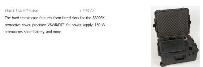
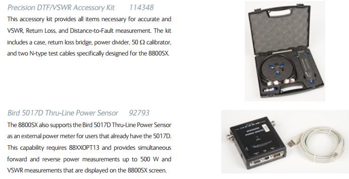
Introduction to the 8800SX Tiles and Controls
|
|
|
- Laurel Clarke
- 5 years ago
- Views:
Transcription


1 Introduction to the 8800SX Tiles and Controls
2 Contents Menu Choose a hyperlink below I/O and Controls Generators Menu Receiver Menu Analyzers Menu Meters Menu Utilities Menu Configuration Menu Options and Accessories External Links External links to related videos: Introducing the Operating GUI Get the latest Data Sheet 8800SX Data Sheet Click on the Click on the Logo to return to this menu shape next to menu items for direct access 1
3 I/O and Controls Controls and Functions (A) (B) (C) (D) (E) (O) (N) (P) (L) (M) (G) (H) (I) (J) (K) (F) (A) Power On/Off Control (B) USB Input (C) Headphone Jack (D) Microphone I/O (E) DMM with Fuse (F) System Menu Button (G) Audio Output Receiver Demod or Function Generator (H) Audio Input Input for Audio Meters Audio Level, Distortion, SINAD (I) Scope Input (J) RF Generator Output Port (-5 to -65 dbm) (K) T/R RF Input/Output Port Direct connect to transceiver Output: -50 to -125 dbm Input: -30 dbm to 50 Watts (125 Watts Duty Cycle) (L)/(M) Bird Thru-Line Power Meter Power Input Power Meter Out (to external 50 Ohm load) (N) Numeric Entry Control (O) Antenna Input: +10 dbm Max Used for off air or low level inputs Output: -30 to -90 dbm (P) Color Resistive Touch display 2
4 I/O and Controls Controls and Functions (A) Battery Power Status Indicator (A) SYS Indicator Green: 88XX Power On/Awake Mode Blue: 88XX Sleep Mode Red: 88XX Shutting Down Green/Red Flashing: Battery Temperature >60 C Green Flashing: Battery Life <5% BAT Indicator Green: Battery at full charge Amber: Battery is charging 3
 Power Supply Input (D) Ground Lug (connect to common ground) (E) Dual USB Inputs (F) Ethernet Interface (D)")
5 I/O and Controls Controls and Functions (A) (B) (F) (E) (A) Remote I/O (factory use only) (B) Battery Cover Battery Fuse (C) Power Supply Input (D) Ground Lug (connect to common ground) (E) Dual USB Inputs (F) Ethernet Interface (D) (C) 4

6 Menu Bar Tile Selections Touch the grey bar to minimize or maximize the menu bar. Touch a Menu Bar Selection to reveal a sub menu. Touch a sub menu item to open that function. 5

7 Menu Bar Menu Reference Chart This chart shows each system menu expanded. Menu items with an arrow to the right indicate that there is a sub menu available. 6
 Advanced Digital Optional Systems P25 Phase II - Option 005 DMR Repeater Option 006 PTC (Positive Train Control) Option 014 Audio Volume (Slider Control) Speaker (ON/OFF)")
8 System Menu Controls and Functions Home Key Pressing the Home button opens/closes the System Menu. Configuration (changing configuration requires system reset). LMR (standard operation) Advanced Digital Optional Systems P25 Phase II - Option 005 DMR Repeater Option 006 PTC (Positive Train Control) Option 014 Audio Volume (Slider Control) Speaker (ON/OFF) Control Audio Squelch (Slider Control) Squelch value indicator Menu Timeout Delay Controls how long the Menu Bar stays open before automatically closing. Backlight (Display Brightness) System Reset (establish default values) Suspend (shuts off display and functions to preserve battery life when not using) Hide Menu (removes the menu bar) Show Icons (shows or hides icon bar) 7
9 ICON Bar ICON Bar Minimized ICON Bar Mid-Size ICON Bar Maximized Freq Flex compensation is enabled Freq Flex compensation is disabled Internal/External 10 MHz Reference Selection/Indicator Take a snapshot (screen image) All tiles are locked in position Tiles are not locked in position and may be moved Remaining battery life indicator Expand information bar 8
10 Generators Menu Selecting the RF Generator Tile Expand the menu bar if minimized Touch the Generators Menu item Touch the Generator Menu selection The Generators Menu allows access to: RF Generator controls AF Generator controls RF Generator Modulation controls 9 9

11 Generators Menu Generator Tile and Controls (Minimized) The minimized Generator Tile allows access to commonly used controls. The Min/Max Icon can be used to minimize or maximize a tile. The Tile Close Icon can be used to remove the tile from the screen. Closing a tile only removes the visibility of the controls. Settings and operation are not changed. 10
 0 to -50 db (use to compensate Generator Output Level for external cable loss or attenuators) Output Port (F) (E) GEN: -5 to -65 dbm ANT: -30 to -90 dbm (H) (F) (I) (G) TR: -50 to -125 dbm")
12 Generators Menu Generator Tile and Controls (Maximized) Generator Frequency (A)/Units (B) 2 MHz to 1 GHz (A) (B) Units GHz, MHz, khz, Hz Output Level (C)/Units (D) dbm, uv, dbuv (C) (D) Output Level Offset (E) 0 to -50 db (use to compensate Generator Output Level for external cable loss or attenuators) Output Port (F) (E) GEN: -5 to -65 dbm ANT: -30 to -90 dbm (H) (F) (I) (G) TR: -50 to -125 dbm PTT Indicator (G) Indicates when microphone PTT is pressed. In this mode, the generator only generates when the microphone PTT button is depressed. Generator Output Enable (H) Turns the RF Generator Output ON or Off Generator Output Level Resolution (I) When enabled, allows RF Generator Level to be lowered by 6 db in 0.1 db steps. Generator must be enabled before using this control. 11


13 Generators Menu Entering Frequencies and Levels Direct Entry Button Entry Scroll Bar Entry When you touch or select a frequency or level entry field, the field will become highlighted and the direct entry pad will be displayed. Direct Entry Pad Using the numeric entries select the desired value. The minus sign is automatically selected for level entries. Terminate the entry with the enter key for level entries. Note: Frequency entries must be terminated with the appropriate GHz, MHz, khz or Hz selection. Touching the Scroll Bar Icon will close the direct entry tile and open a scroll bar where the value can be incremented up or down or the bar can be scrolled. Use the x10 and /10 selections to choose which digit will be moved. To use the button entry, touch the field to be modified and then use the left or right arrow to choose which digit to edit and the up and down arrows to move the value up or down. Use the center button to terminate the entry. 12

14 Generators Menu AF Generator Controls AF Generator Minimized AF Generator Maximized The Fast Stack Icon can be used to stack tiles on top of each other and quickly access the one that is beneath. It acts as a Send to Back feature. Very useful to have many instruments readily available. 13


15 AF Generator Modes GEN1/GEN2 Combine up to two internal function generators with independent frequency and level controls Audio OUT Port can route either the function generator or receiver demod to the Audio OUT connector on the front panel Two Tone Sequential Control Tone A and Tone B frequency, duration and spacing Tone Remote Configure tones for tone remote Tone Sequence Choose between ZVEI1, ZVEI2, ZVEI3, PZVEI, DZVEI, PDZVEI, CCIR1, CCIR2, PCCIR, EEA, EUROSIG, NATEL, EIA or MODAT and two user definable sequences 14

16 Generators Menu Generator Modulation Tile 15
17 Generator Modulation Modes FM/AM Formats Group Analog Modulation Analog INT NONE FM AM Combine two internal modulation sources to modulate the RF Carrier. EXT Apply an external audio signal to the AUD IN Port on the front panel to modulate the RF Carrier. AF GEN Allows control of a single audio generator that can be used simultaneously with the two modulation sources. (RF Generator must be enabled). 16

18 Generator Modulation Modes DTMF Group DTMF Modulation Analog NONE FM AM INT/EXT Configure a constant tone modulation source. External modulation source may be used. DTMF 1 Enter a DTMF tone sequence *# Set State to Off, Cont, Burst or Live DTMF 2 Normal Set Deviation level for DTMF Hi Tone and Lo Tone. Twist Set db of twist and a deviation level. DTMF 3 Set mark and space times. 17
.")
19 Generator Modulation Modes DCS Group DCS Modulation Analog NONE FM AM INT/EXT Configure a constant tone modulation source. External modulation source may be used. AF GEN Allows control of a single audio generator that can be used simultaneously with the two modulation sources. (RF Generator must be enabled). DCS Level entry of deviation level of the DCS Code Code entry for the DCS Code value State allows selection of Off, Normal or Inverted 18

20 Generator Modulation Modes Two Tone, Tone Remote and Tone Sequence Modulation Analog NONE FM AM Group Two Tone Sequential Control Tone A and Tone B frequency, duration and spacing Tone Remote Configure tones for tone remote Tone Sequence Choose between ZVEI1, ZVEI2, ZVEI3, PZVEI, DZVEI, PDZVEI, CCIR1, CCIR2, PCCIR, EEA, EUROSIG, NATEL, EIA or MODAT and two user definable sequences AF GEN Allows control of a single audio generator that can be used simultaneously with the two modulation sources (RF Generator must be enabled) 19
21 Receivers Menu Receivers Selector The receivers selection allows access to: RF Receiver All RF Receiver Controls Tile Decode sub menu Digital Optional Decodes digital information based on technology DCS Decode DCS Decode Window DTMF Decode DTMF Decode Window Tone Decode Tone Decode Window Digital Optional Displays all digital measurements on a single tile Playback Optional Record and Playback for digital radios Analog Displays all analog measurements on a single tile Freq Select Displays access to user defined frequency list 20
22 Receivers Menu Receiver Tile and Controls (Maximized) Receiver Frequency (A)/Units (B) (B) 2 MHz to 1 GHz (A) Units GHz, MHz, khz, Hz Generator Offset (C)/Units (D) (C) (D) (E) RF Signal Generator Frequency Offset dbm, uv, dbuv Lock (E) (F) (G) On: Generator frequency will be offset from the receiver Off: The Generator frequency is unlocked from the receiver Demod (F) (H) (I) FM, AM, Options - P25, DMR, dpmr, ARIB T98, NXDN IF BW (G) (J) (K) 5 khz, 6.25 khz, 8.33 khz, 10 khz, 12.5 khz, 25 khz, 30 khz, 100 khz, 300 khz RF Input Port (H) ANT: +10 dbm Max (L) (M) TR: 50 Watts cont./125 Watts Duty Cycled 21
 Begins search operation for transmit signal. Search range is defined from Config>Freq Find.")
23 Receivers Menu Receiver Tile and Controls (Maximized) AGC (I) (B) Auto/Manual (A) AFBW (Demod Audio BW Filter) (J) LP Filters: 300 Hz, 3 khz, 5 khz, 15 khz (C) (F) (H) (D) (E) (G) (I) HP Filters: 20 Hz, 300 Hz BP Filters: 300 Hz 3 khz, 300 Hz 5 khz, 300 Hz 20 khz plus C-Wt and CCITT Frequency Find (K) Begins search operation for transmit signal. Search range is defined from Config>Freq Find. Apply a signal to the Antenna or TR Port and then touch the Freq Find button to begin the search. Input Level Offset (L) (J) (K) 0 to -50 db (Use to compensate Power/RSSI measurements for external cable loss or attenuators) PreAmp Enable (M) Turns the 20 db Receiver Pre-Amp ON or Off (Ant input only) (L) (M) 22

24 Receiver Menu Receiver Tile and Controls (Minimized) The Minimized Receiver Tile allows access to commonly used controls. The Min/Max Icon can be used to minimize or maximize a tile. The Tile Close Icon can be used to remove the tile from the screen. Closing a tile only removes the visibility of the controls. Settings and operation are not changed. 23


25 Receiver Menu Receiver Decode>Digital The Digital Decode Tile is available with optional digital formats. Decoded Data elements are based on the selected Demod technology like P25, NXDN or DMR for example. 24

26 Receiver Menu Receiver Decode>DCS Decode The DCS Decode panel can decode Transmitter DCS/DPL/CDCSS signals. State Off Normal Inverted 25

27 Receiver Menu Receiver Decode>DTMF Decode The DTMF Decode panel can decode Transmitter DTMF signals. Must be enabled to decode. Shows current and last message. 26


28 Receiver Menu Receiver Decode>Tone Decode The Type selection offers choices of: Two Tone Sequential Tone Remote Tone Sequence Choose between ZVEI1, ZVEI2, ZVEI3, PZVEI, DZVEI, PDZVEI, CCIR1, CCIR2, PCCIR, EEA, EUROSIG, NATEL, EIA or MODAT State is ON to decode or Off The Clear button clears decoded values from the decode window The Source can be either the 8800SX Receiver Demod or the Front Panel Audio IN Port 27

29 Receiver Menu Receiver Digital For Optional digital systems like P25, NXDN, DMR etc. the Digital Demod Tile provides all of the necessary measurements required to properly evaluate a digital signal. Demod Type: P25, DMR, dpmr, ARIBT98, NXDN RF Frequency Error Signal Power/Slot Power for TDMA Signals Broadband Power TX BER BER Patterns are available P , CAL, O.153, FRAMESYNC NXDN 1031, CAL, O.153, FSW+PN9, FRAMESYNC DMR 1031, CAL, O.153, FRAMESYNC Symbol Deviation Modulation Fidelity/FSK Error Symbol Clock Error NAC (P25) Norm Button: Calibrates the Signal Power Meter Rest Acquire: Resets the digital readings Zero RF: Zero s the RF Power Meter (Broadband) 28

30 Receiver Menu Receiver Playback For Optional digital systems like P25, NXDN, DMR etc. the Record and Playback feature is available. Simply Key the Digital Transmitter and press the Record button. Begin talking as desired then de-key the transmitter. The recorded audio will then be played back to the receiver. The recording is automatically saved and may be played back as often as desired. For DMR systems, both simplex and duplex modes are supported. 29

31 Receiver Menu Receiver Analog For standard systems like FM and AM the Analog Demod Tile provides all of the necessary measurements required to properly evaluate an analog signal on a single tile. RF Frequency Error Signal Power/RSSI Broadband Power AM/FM Modulation Audio Counter Audio Distortion Meter Audio SINAD Meter Audio Level Meter The Zero function can be used to zero the Broadband Power Meter for more accurate test results. The Normalize function can be used to calibrate the RSSI meter for more accurate results. 30

32 Receiver Menu Receiver Frequency Select The Frequency Select tile can be used to access a stored frequency list. The list controls the RF Generator and RF Receiver frequencies. The Next and Previous buttons can be used to step through a list of frequencies moving up and down through the list as desired. The Freq List field shows the list name of the currently selected frequency list. The Browse button allows access to choose a different frequency list. Multiple lists may be saved and can be stored in user defined directory structures. Frequency lists can be created through the Config>Freq List selection. These files can be exported and modified with standard spreadsheet software. 31
33 Analyzers Menu Analyzers Selections The Analyzers selection allows access to: Channel Analyzer Look and listen up to a 5 MHz span Wide Analyzer Offers spectrum display with spans up to 50 MHz Oscilloscope View audio signals in time domain Tracking Generator Option 010 Sweep Filters Perform Distance to Fault Plots Perform Return Loss Sweeps Perform VSWR Sweeps Digital Plots Included with any digital option Symbol Distribution Constellation Eye Diagram Power Profile Included with DMR option Shows Power Profile mask limits and pass/fail status for DMR subscriber power ramps. 32

34 Analyzers Menu Channel Analyzer The Channel Analyzer allows viewing of the RF Spectrum up to a 5 MHz span while allowing all other demod activities to continue. The RF frequency and Gain Control (AGC) can be changed by the Receiver Tile when minimized but must be maximized with the icon to change other settings. 33
35 Analyzers Menu Channel Analyzer - Maximized When the Channel Analyzer is maximized, many controls and features become available. The TAB group on the right side allow access to different types of controls. The Tab groups are: Control PBW (Power Bandwidth) Markers Capture OBW (Occupied Bandwidth) Option 011 To choose a different tab, simply touch it. The Tab bar can be scrolled by touching a TAB and sliding it up or down or the arrows may be used to scroll through the Tab list. 34

36 Analyzers Menu Channel Analyzer Maximized Control Tab The Control Tab allows access to the following controls: Center Frequency Vertical Top of Scale Vertical Scale factor 20, 15, 10, 5, 2 db/div. Span 5, 2, 1 MHz, 500, 200, 100 khz, 50, 20 and 10 khz PreAmp control Auto, On, Off With a 10 khz Span and the PreAmp ON, a near -150 dbm noise floor can be seen to look for small signal levels from the ANT Port. Enable On/Off. Analyzer stops sweeping when in the Off condition. Normalize: Calibrates the RSSI Meter and the vertical scale of the analyzer. 35

37 Analyzers Menu Channel Analyzer Maximized PBW Tab The PBW Tab allows access to the following controls and readings: Offset Control Offsets the PBW Markers at the top of the display. RBWe reading This is the Equivalent Resolution BW for the FFT Analyzer. PBW Reading Summation of power in the analyzer trace between the white PBW markers at the top of the display. Power BW Control: 1 khz to 5 MHz in a 1,2,5 sequence. Changes the width of the PBW Markers. FFT Window Type: Hanning or FlatTop Trace Averaging Value Peak Hold Feature 36
 Marker Level Delta Marker Readings Icons allow movement and control of markers The selected marker appears larger than unselected markers.")
38 Analyzers Menu Channel Analyzer Maximized Markers Tab The Markers Tab allows access to the following controls and readings: Up to 6 markers can be enabled simultaneously. Marker Frequency (Entry and indicator) Marker Level Delta Marker Readings Icons allow movement and control of markers The selected marker appears larger than unselected markers. To select a marker, touch the marker control of interest. Add a marker Remove selected marker Move marker to the left or right Move the marker to the beginning or end of the sweep Delta Marker Press delta then press the other marker to view the delta value Peak Max/Min search Move marker to next peak or valley 37


39 Analyzers Menu Channel Analyzer Maximized Capture Tab The Capture Tab allows storage and recall of analyzer traces. Traces are saved as.csv files and may be exported for use with common spread sheet software. A recalled trace will be displayed in white while the live trace is displayed in green. The clear button will remove a recalled trace. 38

40 Analyzers Menu Channel Analyzer Maximized OBW Tab - Optional The Optional OBW Tab provides a measurement of a signals power and occupied bandwidth. A modulated signal will appear lower on the spectrum analyzer than what its actual power level is. Percentile: User entry to define the percent of bandwidth to be displayed by the blue markers. In this case, 99.9% of the RF Energy occupies khz of this trace display. OBW Power: This is the actual RF Energy level that is within the blue markers. In this case, the level is dbm. Mode Live, Peak Hold, Hold Allows measurement of a static trace or a peak hold trace. OBW Enable: Turn this measurement On or Off 39

41 Analyzers Menu Wideband Analyzer The Wideband Analyzer offers all of the same controls as the CH Analyzer with the following exceptions: The Wideband Analyzer offers spans up to 50 MHz. Demodulated audio may be choppy at spans greater than 5 MHz. The AGC operates only in manual mode. The AGC setting must be manually adjusted to best match the level of the incoming signal. 40

42 Analyzers Menu Scope The scope allows viewing of audio signals in the time domain. To access scope controls, expand or maximize the scope with the icon. 41
43 Analyzers Menu Scope - Maximized When the scope is maximized, many controls and features become available. The TAB group on the right side allow access to different types of controls. The Tab groups are: Control Trigger Markers Capture To choose a different tab, simply touch it. The Tab bar can be scrolled by touching a TAB and sliding it up or down or the arrows may be used to scroll through the Tab list. 42

44 Analyzers Menu Scope Maximized Control Tab The Control Tab allows access to the following controls: Source: Scope Input Port, Receiver Demod Signal, Audio Input Port Coupling Scope: AC, DC, GND Demod: DC Audio IN: AC Response Normal Fast: Provides faster scope refresh rate Voffset: Move the trace up or down Vertical: Choose a vertical scale from a list that is suitable for the input signal level Horizontal: Choose a horizontal sweep rate from the following list: 0.5 ms, 1 ms, 2 ms, 4 ms, 6 ms, 10 ms, 20 ms, 50 ms, 100 ms Enable: On/Off (Off disables sweep) 43

45 Analyzers Menu Scope Maximized Trigger Tab The Trigger Tab allows access to the following controls: Trigger Edge Falling Rising Trigger Level Trigger Type Normal Auto 44

46 Analyzers Menu Scope Maximized Markers Tab The Markers Tab allows access to the following controls and readings: Up to 6 Markers can be enabled simultaneously. Marker Time in ms Marker Level Delta Marker Readings Icons allow movement and control of markers The selected marker appears larger than unselected markers. To select a marker, touch the marker control of interest. Add a marker Remove selected marker Move marker to the left or right Move the marker to the beginning or end of the sweep Delta Marker: Press delta then press the other marker to view the delta value Peak Max/Min search Move marker to next peak or valley 45


47 Analyzers Menu Scope Maximized Capture Tab The Capture Tab allows storage and recall of scope traces. Traces are saved as.csv files and may be exported for use with common spread sheet software. A recalled trace will be displayed in white while the live trace is displayed in green. The clear button will remove a recalled trace. 46

48 Analyzers Menu Tracking Generator Maximized Only Option Precision DTF/VSWR Kit Return Loss Bridge Power Divider 50 Ohm Termination Test Cables The Tracking Generator Option offers the following functions: Tracking Generator Used to align or test filters and RF Frequency Response. Return Loss/VSWR Sweeps Measure antenna performance and tuning Requires use of an external Return Loss Bridge Distance to Fault Plots (DTF) Measure cable lengths and find transmission line faults Requires a 50 Ohm Power Divider and 50 Ohm Termination 47
49 Analyzers Menu Tracking Generator Maximized Only Option 010 The TAB group on the right side allow access to different types of controls. The Tab groups are: Control 1 Control 2 Markers Capture To choose a different tab, simply touch it. The Tab bar can be scrolled by touching a TAB and sliding it up or down or the arrows may be used to scroll through the Tab list. 48
50 Analyzers Menu Tracking Generator Control 1 Tab The Tracking Generator Output is always routed to the GEN Output Port. After Calibration with the Set Ref Level, the Y unit can be changed between: dbm (this will remove the Set Ref correction) db (used for Return Loss) VSWR The Control 1 Tab allows access to the following controls: Mode Tracking Generator 2 MHz to 1 GHz Used for filter testing, VSWR and Return Loss sweeps DTF Used for Distance to Fault Plots Control of the sweep can be done by two different methods: Center Frequency and Span Start/Stop Frequency Set Reference Level Calibrates a 0 db reference Connect test cables from the GEN Output to the ANT Input and touch the Set Ref Level button. Note: Make sure that the input is set to ANT on the Control 2 Tab. 49
 The Tracking Generator is unleveled and 0 db represents Maximum Output level Input Port ANT (Normal input) TR")
51 Analyzers Menu Tracking Generator Control 2 Tab Setting the Reference Level to a lower value like -10 dbm will allow measurement maximum depth of a filter. The Control 2 Tab allows access to the following controls: Tracking Generator Level (db) The Tracking Generator is unleveled and 0 db represents Maximum Output level Input Port ANT (Normal input) TR Vertical Scale 2, 5, 10, 15 and 20 db/div. Reference Level ANT: +10 to -70 TR: +50 to -30 Peak Hold PreAmp Control On/Off On ANT Ref Level: -10 to
 Marker Level Delta Marker Readings Icons allow movement and control of markers The Selected marker appears larger than unselected markers.")
52 Analyzers Menu Tracking Generator Markers Tab The Markers Tab allows access to the following controls and readings: Up to 6 markers can be enabled simultaneously. Marker Frequency (Entry and Indicator) Marker Level Delta Marker Readings Icons allow movement and control of markers The Selected marker appears larger than unselected markers. To select a marker, touch the marker control of interest. Add a marker Remove selected marker Move marker to the left or right Move the marker to the beginning or end of the sweep Delta Marker: Press delta then press the other marker to view the delta value Peak Max/Min search Move marker to next peak or valley 51


53 Analyzers Menu Tracking Generator Capture Tab The Capture Tab allows storage and recall of Tracking Generator sweeps. Traces are saved as.csv files and may be exported for use with common spread sheet software. A recalled trace will be displayed in white while the live trace is displayed in green. The clear button will remove a recalled trace. 52


54 Analyzers Menu Digital Plots Optional Included with P25, DMR, NXDN, dpmr, ARIB T98 Digital Plots Tile offers 3 different graphical views of a digital signal Distribution Plot: Shows how often each symbol is accessed. Constellation Plot: Shows Symbol Deviation symmetry. Eye Diagram: Symbol clock error will cause the signal to be unstable around the center vertical line. The Cycle button will rotate through the three different views. The Distribution and Constellation displays can clearly show issues with symbol deviation. The Eye diagram can show issues with Symbol Clock Error. 53


55 Analyzers Menu Power Profile Optional Included with DMR The Power Profile Digital Plot can visually show issues with magnitude error. A mask is provided that the power ramp should fall within. An indicator light is green if the ramp is within the mask and red if any part of the ramp exceeds the mask. This Power ramp shows an issue that is within the mask but results in a magnitude error of more than 2%. 54
56 Meters Menu Meter Selections The Meters Menu selection allows access to the following stand alone meter functions: RSSI DMM SNR (Option 22) Modulation Distortion SINAD AF Counter Audio Level RF RF Error RF Power Inline: Option 12 (Bird 5017D) Option 20 (R&S NRTZ) Power Config 55


57 Meters Menu RSSI Meter Meter Color codes Black: No limit is set Red: Reading is above the upper limit Green: Reading is within limits Blue: Readings is below the lower limit The RSSI Meter has three different sizes with each larger size offering more details. Config Tab Units: dbm, Watts, uwatts, uvolts Range: Various ranges are available depending on the units selection. The default is auto range. Average: Default is 1 but higher averaging values may be entered to settle unstable readings. Ext. Attenuation: This control is also on the Receiver Tile. A negative value entry will compensate the reading to account for cable loss or external attenuators. Normalize This feature will calibrate the RSSI Meter for maximum accuracy. Limits Tab Allows entry of upper and lower limit values. Provides controls to enable use of upper and lower limits independently. This is common to all meters. 56


58 Meters Menu DMM Meter The DMM Meter has three different sizes with each larger size offering more details. Config Tab Range: Various ranges are available depending on the type selection. The default is auto range. Type: DCA, DCV, ACA, ACV Average: Default is 1 but higher averaging values may be entered to settle unstable readings. Peak Hold Enable Peak Hold Clear Peak Hold Reading Enable: Used to disable or enable the readings. Up to 20 amps can be measured with a current shunt (AC24011) using the COM and V/ohms input. Limits Tab Allows entry of upper and lower limit values. Provides controls to enable use of upper and lower limits independently. This is common to all meters. 57

59 Meters Menu SNR Meter Option 022 The SNR Meter Type Demod SNR: Used for transmitter testing Measured signal is the 8800SX Receiver Demod signal. Transmitter is externally modulated with AF Generator 1. Audio SNR: Used for receiver testing Measured signal is Audio IN The 8800SX Modulator is used to modulate the generator that injected into the radio receiver. Range Auto or fixed ranges Enable: Start or stop the SNR Meter operation. Limits Tab Allows entry of upper and lower limit values. Provides controls to enable use of upper and lower limits independently. This is common to all meters. 58


60 Meters Menu Modulation Meter The Modulation Meter has three different sizes with each larger size offering more details. This meter measured the modulation value in either khz for FM Deviation or % for AM Modulation determined by the Receiver Demod type selection. Config Tab Range Average Type: Peak Plus, Peak Minus, PK-PK/2, RMS Units: khz, % or dbr Set Relative Function: Valid only when units setting is set to dbr. This will establish a new 0 db reference. Peak Hold Function: Causes only the highest reading to be displayed. Reset Meter Function: Resets the peak hold reading. Limits Tab Allows entry of upper and lower limit values. Provides controls to enable use of upper and lower limits independently. This is common to all meters. 59


61 Meters Menu Distortion Meter The Distortion Meter has three different sizes with each larger size offering more details. Config Tab Source: Audio In or Receiver Demod Range: Auto or fixed Average: Sets the number of readings to average. For unstable signals, increase averaging. Notch Frequency: Option 021 The Standard Notch Frequency is 1 khz. Option 021 allows the notch frequency to be varied between 1000 Hz and 5000 Hz. Limits Tab Allows entry of upper and lower limit values. Provides controls to enable use of upper and lower limits independently. This is common to all meters. 60


62 Meters Menu SINAD Meter The SINAD Meter has three different sizes with each larger size offering more details. Config Tab Source: Audio In or Receiver Demod Range: Auto or fixed Average: Sets the number of readings to average. For unstable signals, increase averaging. Notch Frequency: Option 021 The Standard Notch Frequency is 1 khz. Option 021 allows the notch frequency to be varied between 1000 Hz and 5000 Hz. Limits Tab Allows entry of upper and lower limit values. Provides controls to enable use of upper and lower limits independently. This is common to all meters. 61

63 Meters Menu AF Counter The AF or Audio Frequency Counter has three different sizes with each larger size offering more details. Config Tab Source: Audio In or Receiver Demod Uses include measuring PL/CTCSS Tone Frequencies Range: Auto or fixed Average: Sets the number of readings to average. For unstable signals, increase averaging Limits Tab Allows entry of upper and lower limit values. Provides controls to enable use of upper and lower limits independently. This is common to all meters. 62


64 Meters Menu Audio Level Meter The Audio Level Meter has three different sizes with each larger size offering more details. Config Tab Source: Audio In or Receiver Demod Uses include measuring PL/CTCSS Tone Frequencies Input Load: High Z, 150, 600 or 1K ohm internal loads Input Range: 3 V or 30 V Detector: RMS, Peak+, Peak-, Pk2Pk Range: Auto or fixed Units: V, mv, dbuv, dbm, Watts, dbr Average: Sets the number of readings to average. For unstable signals, increase averaging External Load Value: Enter an external load factor to calculate dbm when using an external load. Set Relative Function: Set a 0 db Reference for dbr mode Limits Tab Allows entry of upper and lower limit values. Provides controls to enable use of upper and lower limits independently. 63


65 Meters Menu RF Error Meter The RF Error Meter has three different sizes with each larger size offering more details. Config Tab Range: Auto or fixed Average: Sets the number of readings to average. For unstable signals, increase averaging. Default value is 1 Period: Default value is 1 second Units: Hz or PPM Limits Tab Allows entry of upper and lower limit values. Provides controls to enable use of upper and lower limits independently. The RF Error Meter measures the difference in frequency between the 8800SX receiver frequency and the incoming signal. 64

66 Meters Menu RF Power Meter This is a Broadband Power Meter that will show RF energy at the TR Port. The receiver frequency provides a correction factor for the power meter for best accuracy. The RF Power Meter has three different sizes with each larger size offering more details. Config Tab Units: Watts or dbm Range: Auto or fixed Average: Sets the number of readings to average. For unstable signals, increase averaging. Default value is 1 Offset: A negative entry will correct the power meter for an external cable or attenuator loss. Zero Function: Zeros DC Offset from the Broadband Power Meter. Must be done prior to using for maximum accuracy. Meter Type: Average, Minimum, Maximum Clear: Resets minimum or maximum readings Limits Tab Allows entry of upper and lower limit values. Provides controls to enable use of upper and lower limits independently. 65


67 Meters Menu Inline Power Meter Option 012 The Inline Power Meter (Option 012) is an unterminated thru-line power meter with an input for a transmit signal and an output to an external load. This meter is capable of power measurements to 500 Watts Peak. The Power Meter can show both forward and reflected power measurements along with VSWR or Return Loss match making it ideal for testing base stations and transmission lines to the matching antenna. This meter can be used to measure both FM, AM and TDMA signals. Set the Duty Cycle to 50% to measure DMR signals which are on for 30 ms and off for 30 ms. Units Power can be measured in Watts or dbm. Offset entry allows a negative offset to compensate for external cable loss. Match can be displayed as VSWR, Return Loss or RHO A Configuration Screen is available to allow entry of upper and lower limits for color coded pass/fail tests. Option 013 provides metering for use with an External Bird Model 5017D. Option 020 provides metering for use with an External R/S NRTZ Power Sensor. 66

68 Utilities Menu Utilities Selections The Utilities Menu selection allows access to the following stand alone meter functions: Selection of optional languages Presets Three standard presets Seven user definable presets Store/Recall setups with pre-configured samples Cal Software Option installation System information/network settings Software update Freq Flex Timebase optimizaton Aeroflex Self-Test Auto-Test Optional Automated OEM Radio Alignment File Manager Transfer files to and from the 8800SX 67
69 Utilities Menu Presets The small tab at the top center of the display allows access to the launch bar. Simply touch the tab and the launch bar will expand. Presets quickly configure standard tile selections and locations. Press the Utilities Tab and then the Presets Menu to rapidly configure the 8800SX for either analog or digital testing. 68


70 Utilities Menu Store/Recall Setup files store complete instrument configurations that include all settings. To open the menu, simply touch the tab and the menu will expand. Every 8800SX is pre-configured with a large group of sample setups to configure the instrument for a variety of basic tests. Press the Utilities Tab and then the Store/Recall item to gain access to the preconfigured test setups that are within every instrument. 69

71 Utilities Menu Store/Recall Navigation When first entering the Store/Recall Menu, a folder named Sample Setups will be visible. To enter the folder, touch or highlight the Sample Setups item on the list then press the icon to enter the folder. 70

72 Utilities Menu The Sample Setups After entering the Sample Setups folder, there are a variety of basic test folders available. Highlight the Analog FM folder and press the icon to enter the folder. 71

73 Utilities Menu Configure the 8800SX for FM Transmitter Test Highlight the TX_Test_FM setup file and press the Recall button. This will configure the 8800SX to perform basic FM transmitter tests. 72
 Server IP: IP address of a file server Copy from Server: Copies license")
74 Utilities Software - Options The Software Options Screen displays all installed options and allows installation of a new option/license file. Install License: Installs a license file that has been copied into memory Remove License: Password protected (Aeroflex use) Server IP: IP address of a file server Copy from Server: Copies license file from a file server Copy from USB: Copies license file from USB memory Unique ID Status Serial Number: Displays the serial number of the unit To install a new license file: Verify the unit displays a serial number. If the serial number field is blank, contact Aeroflex Customer Service. This procedure can only be completed with a serial number installed in the unit. Unzip the license file to the PC then copy the license file (options.new) to the following directory on a USB Flash Drive: Aeroflex\License. Install the USB flash drive in the USB Connector and wait for the unit to recognize the USB flash drive (approximately 15 seconds). Select Copy from USB button and verify the status field displays Copying from USB Drive. When the copy process is completed, the status field displays Copying from USB Done. 6. Select install license button. When license file installation is complete the status field displays Installing License Done. 7. The unit prompts to cycle power. 73


75 Utilities Software System Status and Hardware Tabs The Software System Status display shows internal temperatures of various internal components. The Software System Hardware display shows hardware revisions of system components. Allows entry of system Time and Date. Provides access to the backlight control which is also on the System Menu. Calibration on Start requires (Aeroflex Use). Alarm On/Off: Turn off the thermal alarm. Leave this in the ON state. 74


76 Utilities Software System Remote and Clone Me Tabs The Software System Remote Tab allows entry of Static or DHCP mode. DHCP: Network assigns an IP address and other parameters. Static: Manually enter IP Address, Subnet Mask, and Gateway values. With networking enabled, it is possible to use a VNC viewer application on a computer to remotely control the 8800SX. Files may also be transferred with a WINSCP application. NOTE: If networking is not required, set the mode to OFF. This will reduce the bootup time of the 8800SX. The Software System Clone Me Tab allows the ability to copy setups files from one 8800SX to another over an Ethernet interface. Enter the source and target IP addresses select Setups Copy. 75

77 Utilities Software Freq-Flex The Freq Flex Function allows calibration of the internal 10 MHz reference to an external RF Signal of known accuracy. This calibration is most accurate at high frequencies. Inject an Unmodulated RF Carrier to the ANT or TR Port. ANT: Level must be between -50 and +10 dbm TR: Level must be between -10 and +20 dbm With external signal applied, touch the Start Calibration to calibrate the internal time base to the frequency of the external reference signal. After calibration the source may be changed between external and internal. Internal: Calibration offset is not applied External: Calibration offset is applied The Icon Bar shows the status and can be used to change from internal to external by touching the icon. 76


78 Utilities Auto-Test System - Optional The 8800SX supports a growing list of automated test and alignment applications and are based on OEM alignment and test specifications for each specific model. Connect the radio s USB Programming Cable from the radio to one of the 8800SX USB Ports. Connect an RF Cable from the radio s TX Output to the 8800SX TR Port. Turn on the radio and select Read Radio and the 8800SX will identify the model of radio that is connected. Either Test Only or Align and Test can be selected. Touch the Run button to execute the process. Test results are automatically stored internally and a filename is created based on the Model, Serial Number and Time/Date stamp. All radio information is captured including radio software versions and options. 77

79 Utilities File Manager The File Manager allows the ability to transfer files from the 8800SX storage directories to a USB memory stick. The 8800SX storage directories include: Auto-Test Results Cable Types: Used for DTF measurements Frequency Lists: Stored Frequency lists Presets Save Recall: Stored setup files Snapshot: Stored screen shots Traces_analyzer: Stored spectrum analyzer traces Traces_oscope: Stored scope traces Traces_track_gen: Stored traces from the Tracking Generator system. Includes DTF and Return Loss Traces. Touch a directory name to highlight it then use the arrow keys next to the path name to navigate to the directory and file group of interest. Touch the usbstick_sda1 folder and use the path arrows above to navigate to the USB folder of interest. Files can now be transferred from either direction. 78
80 Configuration Menu Configuration Selections The Configuration Menu selection allows access to the following features: Audio Input and Output signal routing Input and Output control Digital Included with any digital option Configure limits and averaging for all digital meters Freq Find Configure parameters used by Receiver Frequency Find Feature Analog Configure limits and averaging for all analog meters Channel Plan Option 15 AAR Channel Plan Tone Configure User Definable Tone Sequence Freq List Configure frequency lists 79

81 Config Audio The Audio Configuration Tile is used to configure Audio Routing, Input Range and Filtering. Audio Tab Audio IN Load: High Z, 150 Ohm, 600 Ohm or 1 k Ohm internal load selections. Audio IN Range: 3 V or 30 V Set this range to be appropriate for audio signals coming into the Audio IN Port. Audio OUT Port AF GEN: Audio Generator is routed to the AUD OUT Port. DEMOD: Receiver Demod Audio is routed to the AUD OUT Port. Audio IN Filter: Choose from a list of low pass, high pass and band pass filters to filter audio coming into the AUD IN Port. Routing Tab Define audio signal that various devices may be evaluating. Choose between Audio IN, Receiver Demod and others. Selections are different for different devices. Audio in Demod AF Gen Audio in Demod Scope Demod Audio in Audio in Demod Scope Audio in Audio in Demod 80


82 Config Digital Provided with any Optional Digital System The Digital Config Tile provides access to upper and lower limit entries for all digital meters. Meter averaging can also be set for each meter independently. Meters are separated by tab selections on the right side of the display. This is a fast method to configure meter limits if multiple meters are to be configured. 81

83 Config Frequency Find The Frequency Find Configuration Tile allows configuration of the frequency search parameters. Start Frequency: Begin the search at start frequency Stop Frequency: Search up to the stop frequency Channel Spacing: Step size of the search Threshold: Signal must be greater than this value To initiate a search for a transmitter, use the Freq Find Button on the Receiver Tile. 82


84 Config Analog Config The Analog Config Tile provides access to upper and lower limit entries for all analog meters. Meters are separated by tab selections on the right side of the display. This is a much faster method to configure meter limits if multiple meters are to be configured. 83

85 Config Channel Plan Option 015 Option 015 is for the AAR Channel plan used by the various railroads in North America including: Norfolk Southern CSX BNSF UPRR P&W, MBTA and Amtrack A channel entry controls the generator and receiver frequencies along with the modulator and demodulator settings. Channels 5 97, are used for FM Channels are used for NXDN Technology 84


86 Config Tone The 8800SX provides entries for two user definable tone sequences for use with Tone Sequential. Separate lists are available for the RF Generator Modulator and the Audio Generator. Tones 0-7 and 8-F can be defined for frequency, duration, and pause. Use the AF Generator or RF Generator Modulator Tone Seq Tab to send the sequence. 85

87 Config Frequency List Frequency lists can be exported and modified with standard spreadsheet software. After being modified, they can be imported back. Use the File Manager to transfer files. The Frequency List configuration allows entries in a variety of ways. Each entry allows entry of a user definable label. List Type Analog Enter Gen/Rec frequencies, Gen Level Set Lvl control On: Sets the Gen Level Off: Does not set the Gen Level PL DCS: Adds the ability to set Mod1 and Mod2 frequency and Deviation levels along with on/off controls. PL or DCS can be chosen for Mod 2. P25: Adds the ability to add a NAC for P25 Encode. DMR: Adds the ability to enter a Color Code and Call ID for DMR Encode. NXDN: Adds the ability to enter a RAN Code and Baud Rate for NXDN Encode dpmr: Adds the ability to enter CC, Call ID, Unit ID, and Comms Format. 86


88 Putting It All Together Screen Arrangements Use Tile Stacking and the Fast Stack Icon to quickly access any controls or tiles that might be useful for specific tasks. Use meter configuration screens to set limits on specific meters of interest for fast pass/fail tests. Save the configuration as a preset to store only tile locations or as a setup to store all settings and tile locations. 87

89 8800SX Options and Accessories 88
90 Questions or Comments? Contact Information For information about pricing for our products, contact the sales office by calling VIAVI Solutions at (800) or ing For technical/product support, calibration, maintenance and general customer service inquiries, you can contact our help desk by clicking here, calling (800) , or ing Click here for more information on the 3920B and latest software versions and training materials. 89
Basic Transceiver tests with the 8800S
 The most important thing we build is trust ADVANCED ELECTRONIC SOLUTIONS AVIATION SERVICES COMMUNICATIONS AND CONNECTIVITY MISSION SYSTEMS Basic Transceiver tests with the 8800S Basic Interconnects Interconnect
VIAVI Solutions 3550 Series Software Release Notes
 Version 2.3.1 Release Notes 7/31/2018 1. A new field for temperature has been added to Option 14 Bird Thru Line Power meter. 1. The marker frequency entries are not altered by changing the center frequency
VIAVI Solutions 8800 Series Software Release Notes
 Version 2.3.1 Release Notes 7/31/2018 1. A new field for temperature has been added to Option 13 Bird Thru Line Power meter. 1. The marker frequency entries are not altered by changing the center frequency
8800SX DMR Repeater Test Option 06
 8800SX DMR Repeater Test Option 06 DMR Repeater Test Option The DMR Repeater test option allows testing of a DMR Repeater that is in conventional DMR Mode. Trunking or analog configurations are not supported.
APX Mobile and Portable Automated Test and Alignment
 APX Mobile and Portable Automated Test and Alignment Software Updates First things first! Be sure to check that you are running the latest software versions for the 8800SX and its applications. Visit the
FM Modulation. Accuracy. Total. Harmonics. Input Range. Frequency. Range. Deviation. Range. Modulation. Accuracy. Audio In Switchable Loads.
 Product Specification VIAVI 3550R Touch-Screen Radio Test System VIAVI Solutions General Specifications RF Signal Generator Output SSB Phase Noise 2 MHz - 1 GHz (usable from 500 khz) T/R Port: -50 to -125
Testing Motorola DMR MOTOTRBO Radios with the Cobham 3920B Radio Test Platform
 Application Note Testing Motorola DMR MOTOTRBO Radios with the Cobham 3920B Radio Test Platform The Cobham 3920B is the complete tool for anyone wishing to test Analog or Digital MOTOTRBO mobile or portable
3900 Series Digital Radio Test Set DMR Option Manual. Issue-10
 EXPORT CONTROL WARNING: This document contains controlled technical data under the jurisdiction of the Export Administration Regulations (EAR), 15 CFR 730-774. It cannot be transferred to any foreign third
Wireless Analog and Digital Radio Test Set. Hybrid Bench and Portable Radio Test System for Complete Testing of Analog and Digital Radios
 Wireless 8800 Analog and Digital Radio Test Set Hybrid Bench and Portable Radio Test System for Complete Testing of Analog and Digital Radios Standing on 50 years of experience and leadership in radio
8800SX Digital Radio Test Set
 8800SX Digital Radio Test Set Hybrid Bench and Field Portable Design 2016 Brochure The most important thing we build is trust 2 Cobham 8800SX Digital Radio Test Set The NEW 8800SX expands upon the unprecedented
Quick Site Testing with the 8800SX
 Quick Site Testing with the 8800SX Site Testing with the 8800SX Basic Tests 5 site testing involves several tests to verify site operation. NOTE: This is not intended to be a complete commissioning procedure.
8800SX. Advanced Analog and Digital Radio Test for Both Bench and Field Test Environments. Digital Radio Test Set. Data Sheet
 8800SX Digital Radio Test Set Data Sheet The most important thing we build is trust Advanced Analog and Digital Radio Test for Both Bench and Field Test Environments The NEW 8800SX expands upon the unprecedented
3900 Series Digital Radio Test Set. NXDN Remote Programming Manual Issue-8
 EXPORT CONTROL WARNING: This document contains controlled technical data under the jurisdiction of the Export Administration Regulations (EAR), 15 CFR 730-774. It cannot be transferred to any foreign third
Understanding the Precision Antenna, Cable, and Power Measurements on the 3550 Radio Test System
 Application Note Understanding the Precision Antenna, Cable, and Power Measurements on the 3550 Radio Test System The Aeroflex 3550 Radio Test System now includes new methods for more accurately measuring
FREEDOM Communications System Analyzer R8600 DATA SHEET
 FREEDOM Communications System Analyzer R8600 DATA SHEET Table of Contents Operating/Display Modes 3 General 3 Generator (Receiver Test) 4 Receiver (Transmitter Test) 5 Spectrum Analyzer 6 Oscilloscope
8800SX. Advanced Analog and Digital Radio Test Set for Bench and Field Environments. Digital Radio Test Set. Data Sheet
 8800SX Digital Radio Test Set Data Sheet The most important thing we build is trust Advanced Analog and Digital Radio Test Set for Bench and Field Environments The NEW 8800SX expands upon the unprecedented
FREEDOM Communications System Analyzer R8100 DATA SHEET
 FREEDOM Communications System Analyzer R8100 DATA SHEET Table of Contents Operating/Display Modes 3 General 3 Generator (Receiver Test) 4 Receiver (Transmitter Test) 5 Spectrum Analyzer 6 Oscilloscope
8800S Digital Radio Test Set
 8800S Digital Radio Test Set Hybrid Bench and Field Portable Design 2015 Brochure The most important thing we build is trust 2 Cobham 8800S Digital Radio Test Set The NEW 8800S expands upon the unprecedented
VIAVI 3550R. Touch-Screen Radio Test System. Product Brief
 Product Brief VIAVI 3550R Touch-Screen Radio Test System VIAVI Solutions The complete portable, on site radio communication test system for analog and digital communication systems. Now available with
8800SX. Advanced Analog and Digital Radio Test Set for Bench and Field Environments. Digital Radio Test Set. Data Sheet
 8800SX Digital Radio Test Set Data Sheet The most important thing we build is trust Advanced Analog and Digital Radio Test Set for Bench and Field Environments The 8800SX expands upon the unprecedented
Installed Radio Testing with the 3500
 Application Note Installed Radio Testing with the 3500 Aeroflex has uniquely designed the Aeroflex 3500 portable radio test set for complete testing of installed radio communication systems. The 3500 is
FREEDOM Communications System Analyzer R8000C DATA SHEET
 FREEDOM Communications System Analyzer R8000C DATA SHEET Table of Contents Operating/Display Modes 3 General 3 Generator (Receiver Test) 4 Receiver (Transmitter Test) 5 Spectrum Analyzer 6 Oscilloscope
3550R. Touch-Screen Radio Test System. Data Sheet. The most important thing we build is trust
 3550R Touch-Screen Radio Test Data Sheet The most important thing we build is trust The complete portable, on site radio communication test system for analog and digital communication systems. Now available
The Complete Portable, On Site Radio Communication Test System for Analog and Digital Communication Systems
 Wireless 3550 Touch-Screen Radio Test System The Complete Portable, On Site Radio Communication Test System for Analog and Digital Communication Systems Full Feature RF Test Functions -140 dbm DANL Spectrum
8800SX Series P25 Phase II Test Option 05
 8800SX Series P25 Phase II Test Option 05 8800SX P25 Phase 2 Operation Introduction The P25 Phase 2 Option 05 allows transmitter and receiver testing of both subscriber portable and mobile radios as well
3550R. Touch-Screen Radio Test System. Data Sheet. The most important thing we build is trust
 3550R Touch-Screen Radio Test Data Sheet The most important thing we build is trust The complete portable, on site radio communication test system for analog and digital communication systems. Now available
The Complete Portable, On Site Radio Communication Test System for Analog and Digital Communication Systems. Multi-Function Oscilloscope
 Wireless 3550 Touch-Screen Radio Test System The Complete Portable, On Site Radio Communication Test System for Analog and Digital Communication Systems The 3550. The first truly portable touch-screen
DMR Application Note Testing MOTOTRBO Radios On the R8000 Communications System Analyzer
 DMR Application Note Testing MOTOTRBO Radios On the R8000 Communications System Analyzer April 2 nd, 2015 MOTOTRBO Professional Digital Two-Way Radio System Motorola and MOTOTRBO is registered in the U.S.
PC Tune PC Tune Test Procedures for 5100 Series Portable Radios
 PC Tune PC Tune Test Procedures for 5100 Series Portable Radios Part Number 002-9998-6513014 August 2008 Copyright 2006, 2007, 2008 by EFJohnson Technologies The EFJohnson Technologies logo, PC Configure,
Application Note: DMR Application Note Testing MOTOTRBO Radios On the Freedom Communications System Analyzer
 : DMR Application Note Testing MOTOTRBO Radios On the Freedom Communications System Analyzer MOTOTRBO Professional Digital Two-Way Radio System Motorola and MOTOTRBO is registered in the U.S. Patent and
FREEDOM Communications System Analyzer R8100 DATA SHEET
 FREEDOM Communications System Analyzer R8100 DATA SHEET Table of Contents Operating/Display Modes 3 General 3 Generator (Receiver Test) 4 Receiver (Transmitter Test) 5 Spectrum Analyzer 6 Oscilloscope
DSA-815 Demo Guide. Solution: The DSA 800 series of spectrum analyzers are packed with features.
 FAQ Instrument Solution FAQ Solution Title DSA-815 Demo Guide Date:08.29.2012 Solution: The DSA 800 series of spectrum analyzers are packed with features. Spectrum analyzers are similar to oscilloscopes..
FREEDOM Communications System Analyzer R8000C DATA SHEET
 FREEDOM Communications System Analyzer R8000C DATA SHEET Table of Contents Operating/Display Modes General 3 3 Generator (Receiver Test) 4 Receiver (Transmitter Test) 5 Spectrum Analyzer 6 Oscilloscope
Testing Motorola P25 Conventional Radios Using the R8000 Communications System Analyzer
 Testing Motorola P25 Conventional Radios Using the R8000 Communications System Analyzer Page 1 of 24 Motorola CPS and Tuner Software Motorola provides a CD containing software programming facilities for
Signal Generators for Anritsu RF and Microwave Handheld Instruments
 Measurement Guide Signal Generators for Anritsu RF and Microwave Handheld Instruments BTS Master Spectrum Master Tracking Generator Option 20 Vector signal Generator Option 23 Anritsu Company 490 Jarvis
8800SX Digital Radio Test Set
 8800SX Digital Radio Test Set Hybrid Bench and Field Portable Design Brochure The most important thing we build is trust 2 Cobham 8800SX Digital Radio Test Set The NEW 8800SX expands upon the unprecedented
FREEDOM Communications System Analyzer R8100 DATA SHEET
 FREEDOM Communications System Analyzer R8100 DATA SHEET Table of Contents Operating/Display Modes General 3 3 Generator (Receiver Test) 4 Receiver (Transmitter Test) 5 Spectrum Analyzer 6 Oscilloscope
Application Note: Testing P25 Conventional Radios Using the Freedom Communications System Analyzers
 : Testing P25 Conventional Radios Using the Freedom Communications System Analyzers FCT-1007A Motorola CPS and Tuner Software Motorola provides a CD containing software programming facilities for the radio
R2590 Communications System Analyzer. High-end Analyzer at a Low-end Price
 R2590 Communications System Analyzer High-end Analyzer at a Low-end Price R2590 Communications System Analyzer Big solutions on a small budget. The R2590 system analyzer sets a new standard for value in
2801 Multilock. Communications System Analyzer. Data Sheet. Boosting wireless efficiency
 Data Sheet 2801 Multilock Communications System Analyzer Boosting wireless efficiency A real multi-talented instrument the Willtek 2801 Multilock The Willtek 2801 Multilock is a test instrument for multiple
CAD-MF. PC-Based Multi-Format ANI & Emergency ANI Display Decoder. Manual Revision: Covers Firmware Revisions: CAD-MF: 1.
 CAD-MF PC-Based Multi-Format ANI & Emergency ANI Display Decoder Manual Revision: 2010-05-25 Covers Firmware Revisions: CAD-MF: 1.0 & Higher Covers Software Revisions: CAD: 3.21 & Higher Covers Hardware
Agilent 8920A RF Communications Test Set Product Overview
 Agilent 8920A RF Communications Test Set Product Overview Cut through problems faster! The Agilent Technologies 8920A RF communications test set was designed to solve your radio testing and troubleshooting
Mastr III P25 Base Station Transmitter Tune-up Procedure
 Mastr III P25 Base Station Transmitter Tune-up Procedure 1. Overview The Mastr III Base Station transmitter alignment is performed in several steps. First, the Transmit Synthesizer module is aligned to
Appendix G: IFR 8800 Test Procedures MAINTENANCE GUIDE.
 Appendix G: IFR 8800 Test Procedures MAINTENANCE GUIDE www.codanradio.com MAINTENANCE GUIDE MT-4E ANALOG & P25 DIGITAL RADIO SYSTEMS Contents Appendix G: IFR 8800 Test Procedures...1 MT-4E Testing with
AirScope Spectrum Analyzer User s Manual
 AirScope Spectrum Analyzer Manual Revision 1.0 October 2017 ESTeem Industrial Wireless Solutions Author: Date: Name: Eric P. Marske Title: Product Manager Approved by: Date: Name: Michael Eller Title:
ATB-7300 to NAV2000R Product Comparison
 ATB-7300 to NAV2000R Product Comparison Aeroflex Aeroflex Parameter / Function ATB-7300 NAV2000R Collins 479S-6A simulation Yes Yes ARINC 410 Auto-Tune Compatible No Yes Signal Generator Frequency Freq
Wireless Portable Radio Communications Test Set. Advanced Test Equipment Rentals ATEC (2832)
") Established 1981 Advanced Test Equipment Rentals www.atecorp.com 800-404-ATEC (2832) Wireless 3500 Portable Radio Communications Test Set Designed to dramatically improve radio operational time in vehicle
Established 1981 Advanced Test Equipment Rentals www.atecorp.com 800-404-ATEC (2832) Wireless 3500 Portable Radio Communications Test Set Designed to dramatically improve radio operational time in vehicle
Technical Equipment Specification
 STATE OF CALIFORNIA Office of the State Chief Information Officer Public Safety Communications Division Technical Equipment Specification Equipment Type: Transmitter/Receiver Mobile Relay/Base/Control
8800SX TETRA Base Station Operation
 8800SX TETRA Base Station Operation 8800SX TETRA Base Station Test The 8800SX TETRA Base Station Test option utilizes the ETSI standard defined TETRA T1 test mode. - ETSI is the European Telecommunications
Suitable firmware can be found on Anritsu's web site under the instrument library listings.
 General Caution Please use a USB Memory Stick for firmware updates. Suitable firmware can be found on Anritsu's web site under the instrument library listings. If your existing firmware is older than v1.19,
Power Meter. Measurement Guide. for Anritsu RF and Microwave Handheld Instruments BTS Master Site Master Spectrum Master Cell Master
 Measurement Guide Power Meter for Anritsu RF and Microwave Handheld Instruments BTS Master Site Master Spectrum Master Cell Master Power Meter Option 29 High Accuracy Power Meter Option 19 Inline Peak
3900 Series Digital Radio Test Set P25 Remote Programming Manual
 EXPORT CONTROL WARNING: This document contains controlled technical data under the jurisdiction of the Export Administration Regulations (EAR), 15 CFR 730-774. It cannot be transferred to any foreign third
CCIR EURO DZVEI NAT EL EEA CCIRH 5/6 T ONE DDZVEI ZVEI EIA CCIRH4 POCSAG
 however our new color display does just that. With high resolution and improved visibility, the COM-120C provides high performance test features with even easier to read test results. With the RCC Signaling
IC-400pro - RADIOAFICION.COM
 PROCEDURES IC-400pro - 5- PREPARATION When you adjust the contents on pages 5-5 and 5-6, SOFT- WARE, the optional CS-400PRO ADJ SOFTWARE (Rev..0 or later), *OPC- JIG CABLE (modified OPC- CLONING CABLE;
GC723A / GC724B Cable and Antenna Analyzer
 www.gctm.net GC723A / GC724B Cable and Antenna Analyzer GC723A / GC724B Cable and Antenna Analyzer Introduction A large number of abnormal cell site problems are typically caused by the antenna system,
Military Communications
 Military Communications 3515A Military Portable Radio Communications Test Set New Integrated Audio Connectors The Aeroflex 3515A was developed for military use and offers rugged construction and testing
Test Equipment Solutions Datasheet
 Test Equipment Solutions Datasheet Test Equipment Solutions Ltd specialise in the second user sale, rental and distribution of quality test & measurement (T&M) equipment. We stock all major equipment types
TV SIGNAL LEVEL METER USER MANUAL
 TV SIGNAL LEVEL METER USER MANUAL - 0 - 1. Overview (1) (1) RF input (2) (3) A D E B C (2) Speaker (3) LCD display (4) Charger indicator (5) RS232 communication port (6) DC-IN port F G A. The battery icon
JD723A/JD724B/JD726A Cable and Antenna Analyzers
 COMMUNICATIONS TEST & MEASUREMENT SOLUTIONS JD723A/JD724B/JD726A Cable and Antenna Analyzers Key Features Portable and lightweight handheld instrument. Built in wireless frequency bands as well as the
FCC ID: AXI IC: 10239A Alignment
 Introduction The VX-261 is carefully aligned at the factory for the specified performance across the frequency range specified for each version. Realignment should therefore not be necessary except in
Localizer provides signal generation over the Localizer band of to MHz with 90 Hz and 150 Hz tones, amplitude modulated
 The IFR 4000 verifies the operation and installation of ILS, VOR and Marker Beacon receivers and VHF/UHF AM/FM and HF AM/SSB transceivers. The IFR 4000, with its lightweight size (under 8 lbs.), long run
APPENDIX A PARAMETER DESCRIPTIONS
 APPENDIX A PARAMETER DESCRIPTIONS CONTENTS Page INTRODUCTION A.5 CHANNEL PARAMETERS #101 -#102 Channel Frequencies A.5 #103 Microcomputer Clock Offset A.6 #104 Transmitter Power A.6 #105 Squelch A.6 #106
JD746A/JD786A CellAdvisor RF Analyzer
 JD746A/JD786A CellAdvisor RF Analyzer JD746A JD786A Spectrum Analyzer: 100 khz to 4 GHz 9 khz to 8 GHz Cable and Antenna Analyzer: 5 MHz to 4 GHz 5 MHz to 6 GHz RF Power Meter: 10 MHz to 4 GHz 10 MHz to
WPE 48N USER MANUAL Version1.1
 Version1.1 Security instructions 1. Read this manual carefully. 2. Follow all instructions and warnings. 3. Only use accessories specified by WORK PRO. 4. Follow the safety instructions of your country.
OPERATOR S MANUAL KYODO WEST MODEL KG506 FULL-DUPLEX MOBILE. Preliminary
 OPERATOR S MANUAL KYODO WEST MODEL KG506 FULL-DUPLEX MOBILE Preliminary 1.0 INTRODUCTION Thank you for purchasing the KYODO WEST MODEL KG506 Full-Duplex Mobile Radio. This manual contains information to
Tetra Base Station Test and Monitoring
 Tetra Base Station Test and Monitoring Introduction to Tetra Base Station Test and Monitoring The two options TETRA Base Station Monitoring ( R8-TETRA_BSM) and TETRA Base Station T1 Test (R8-TETRA_BST1)
Wireless. COM-120C Communications Service Monitor.
 Wireless COM-120C Communications Service Monitor The new standard for 1 GHz Communication Service Monitors based on Aeroflex s highly successful line of Radio Test Sets New color display provides excellent
Military Communications
 Military Communications 3515 Series Portable Radio Communications Test Set The Aeroflex 3515 is a first-line radio test set designed to verify that portable radios, man-pack radios, vehicle and aircraft
SDI. Table of Contents
 NMSC-2 User Manual 2 Table of Contents Introduction........ 4 Hardware Installation.... 5 NMSC Power On.. 8 Overview... 9 FFT Measurement Screen.. 10 FFT Setup..... 11 FFT Detector..... 14 FFT Calibration.....
HP 8920B RF Communications Test Set
 H HP 8920B RF Communications Test Set Technical Specifications NEW Test Features New, intuitive call processing and on-call parametric test interface. High-level HP-IB commands simplify call processing
Roger Kane Managing Director, Vicom Australia
 Understanding and testing of DMR standard Roger Kane Managing Director, Vicom Australia @CommsConnectAus#comms2014 Presentation Title: Understanding and Testing DMR Speaker: Roger Kane @CommsConnectAus
HP 8921A Cell Site Test Set. Product Note AMPS Base Station Testing
 HP 8921A Cell Site Test Set Product Note 8921-1 AMPS Base Station Testing AMPS Base Station Testing This product note describes manual operation of the HP 8921A Cell Site Test Set (or HP 8920A RF Communications
ICOM IC-R8600 Specifications, Features & Options
 General Frequency coverage IC-R8600 USA: 0.010000 821.999999MHz*, 851.000000 866.999999MHz, 896.000000 3000.000000MHz (*Guaranteed range: 0.100000 821.999999MHz) Antenna connector Frequency stability Mode
AT-D868UV CodePlug Programming Guide
 INTRODUCTION The AnyTone D868UV radio is a VHF and UHF radio with both Digital DMR (Tier I and II) and Analog capabilities. It offers a total of 4,000 channels (Analog and Digital) and up to 130,000 contacts,
i2820h (USA) ie2820(europe)
 ie2820(europe)") January 2007 DUAL BAND TRANSCEIVERS i2820h (USA) ie2820(europe) The above photo shows the IC-2820H. The IC-E2820 differs slightly from this photo. Icom proudly announces the debut of the new dual band
January 2007 DUAL BAND TRANSCEIVERS i2820h (USA) ie2820(europe) The above photo shows the IC-2820H. The IC-E2820 differs slightly from this photo. Icom proudly announces the debut of the new dual band
PXIe Contents CALIBRATION PROCEDURE
 CALIBRATION PROCEDURE PXIe-5632 This document contains the verification and adjustment procedures for the PXIe-5632 Vector Network Analyzer. Refer to ni.com/calibration for more information about calibration
Measurement Procedure & Test Equipment Used
 Measurement Procedure & Test Equipment Used Except where otherwise stated, all measurements are made following the Electronic Industries Association (EIA) Minimum Standard for Portable/Personal Land Mobile
Studio Broadcast System
 SET UP and USE 1. REGULATORY AND COMPLIANCE STATEMENTS... 3 2. OVERVIEW 2.1 Core Performance Targets 2.2 Specifications 2.3 System Components 2.4 System Block Diagram 3. BP24 UWB BODY PACK TRANSMITTER...
ID-5100 User Evaluation & Test Report
 ID-5100 User Evaluation & Test Report By Adam Farson VA7OJ/AB4OJ Iss. 1, August 13, 2014. Part I: Brief User Evaluation. Introduction: This report describes the evaluation and lab test of ID-5100 S/N 05001175.
External Source Control
 External Source Control X-Series Signal Analyzers Option ESC DEMO GUIDE Introduction External source control for X-Series signal analyzers (Option ESC) allows the Keysight PXA, MXA, EXA, and CXA to control
3GPP2 Signal Analyzer
 Measurement Guide 3GPP2 Signal Analyzer for Anritsu RF and Microwave Handheld Instruments BTS Master, Cell Master, Spectrum Master RF Demod OTA CDMA Option 42 Option 43 Option 33 EV-DO Option 62 Option
XOPT240 P25 AES Encryption (Requires 390XOPT200) (U.S. DoC License Required, Contact Wichita Export Administration for $2,332.
 (U.S. DoC License Required, Contact Wichita Export Administration for $2,332.") 3920 Description MSRP Effective 91164 3920B Digital Radio Test Set 1MHz - 1GHz with Standard Analog Duplex Operation and DMM $32,855.00 1-Apr-16 83359 390XOPT110 TETRA MS (Mobile Station Testing) $10,494.00
3920 Description MSRP Effective 91164 3920B Digital Radio Test Set 1MHz - 1GHz with Standard Analog Duplex Operation and DMM $32,855.00 1-Apr-16 83359 390XOPT110 TETRA MS (Mobile Station Testing) $10,494.00
Digital HF Receiver WJ-8723
 Developmental Specification WATKINS-JOHNSON April 1996 Digital HF Receiver WJ-8723 Description The WJ-8723 is a fully synthesized, general-purpose HF receiver that monitors RF communications from 5 khz
TABLE OF CONTENTS. Keypad Programming Manual 1
 TABLE OF CONTENTS How To Program Radios...2 Keypad Programming...2 A. Navigation...3 1. Group Parameters (CH 00)...4 2. Channel Parameters (CH 01 - CH20)...4 3. Global Parameters (GRP 00)...5 B. Group
Advanced Test Equipment Rentals ATEC (2832) Contents
 Contents") i Established 1981 Advanced Test Equipment Rentals www.atecorp.com 800-404-ATEC (2832) Contents Appendix B: IFR COM-120 Test Procedures...1 MT-4E Testing with the IFR COM-120 by Aerofl ex...1 General Set-Up
i Established 1981 Advanced Test Equipment Rentals www.atecorp.com 800-404-ATEC (2832) Contents Appendix B: IFR COM-120 Test Procedures...1 MT-4E Testing with the IFR COM-120 by Aerofl ex...1 General Set-Up
Why Modern Servicing Requires Complete Waveform & Circuit Analyzing!
 Why Modern Servicing Requires Complete Waveform & Circuit Analyzing! DC Bias Voltages DC Currents Resistance AC Signals Of Various Waveshapes & Amplitudes Continuity Of Circuit Paths & Components If you
"Terminal RG-1000" Customer Programming Software. User Guide. August 2016 R4.3
 "Terminal RG-1000" Customer Programming Software User Guide August 2016 R4.3 Table of Contents Table of Contents Introduction 2 3 1.1 Software installation 3 1.2 Connecting the RG-1000 GATEWAYs to the
Spectrum Analyzer. Spectrum Analyzer. Antenna Panel Inputs. Auxiliary Antenna Inputs. Two models available: 24 GHz and 8 GHz OSCOR
 Whip antenna extension connector Auto Switching (utilizes 5 independent antennas) OSCOR ADVANTAGES FULL 24 GHz COVERAGE Headphone Jack SWEEPS FROM 10 khz TO 24 GHz AT 12.2 khz STEPS IN LESS THAN 1 SECOND
JEM Radio II Operation Guide. Manual P/N M Victor Place Colorado Springs, Colorado
 JEM Radio II Manual P/N M09999-999 2115 Victor Place Colorado Springs, Colorado 80915 800.284.0399 www.jemcom.com Table of Contents Display... 3 Channel Entry... 4 Shortcuts... 4 Text Messages... 4 Buttons...
HP 33120A Function Generator / Arbitrary Waveform Generator
 Note: Unless otherwise indicated, this manual applies to all Serial Numbers. The HP 33120A is a high-performance 15 MHz synthesized function generator with built-in arbitrary waveform capability. Its combination
Spectrum Analyzers 2680 Series Features & benefits
 Data Sheet Features & benefits n Frequency range: 9 khz to 2.1 or 3.2 GHz n High Sensitivity -161 dbm/hz displayed average noise level (DANL) n Low phase noise of -98 dbc/hz @ 10 khz offset n Low level
y Over-the-air radio testing ystandard instruments included in the 3515: yrf Signal Generator ymodulation Meters yaudio Generators y RF Power Meters
 Product Brief VIAVI 3515 Series Portable Radio Communications Test Set VIAVI Solutions The VIAVI Solutions 3515 is a first-line radio test set designed to verify that portable radios, man-pack radios,
Measuring Frequency Settling Time for Synthesizers and Transmitters
 Products: FSE Measuring Frequency Settling Time for Synthesizers and Transmitters An FSE Spectrum Analyser equipped with the Vector Signal Analysis option (FSE-B7) can measure oscillator settling time
PGT313 Digital Communication Technology. Lab 3. Quadrature Phase Shift Keying (QPSK) and 8-Phase Shift Keying (8-PSK)
 and 8-Phase Shift Keying (8-PSK)") PGT313 Digital Communication Technology Lab 3 Quadrature Phase Shift Keying (QPSK) and 8-Phase Shift Keying (8-PSK) Objectives i) To study the digitally modulated quadrature phase shift keying (QPSK) and
PGT313 Digital Communication Technology Lab 3 Quadrature Phase Shift Keying (QPSK) and 8-Phase Shift Keying (8-PSK) Objectives i) To study the digitally modulated quadrature phase shift keying (QPSK) and
ELECRAFT KX3 EXTENDED VFO TEMPERATURE COMPENSATION PROCEDURE Copyright 2012 Elecraft LLC Rev. A9, November 14, 2012
 ELECRAFT KX3 EXTENDED VFO TEMPERATURE COMPENSATION PROCEDURE Copyright 2012 Elecraft LLC Rev. A9, November 14, 2012 Introduction The KX3 standard VFO temperature compensation is entirely adequate for most
MicroFox2 Manual. Version 0.5 August 28, 2017
 Overview The Byonics MicroFox2 (MF2) is a small, 500mW, frequency agile 2-meter transceiver designed for hidden transmitter hunts, also called T-hunts, foxhunts, and ARDF. It is based on the Byonics MicroFox-PicCon,
PXA Configuration. Frequency range
 Keysight Technologies Making Wideband Measurements Using the Keysight PXA Signal Analyzer as a Down Converter with Infiniium Oscilloscopes and 89600 VSA Software Application Note Introduction Many applications
Quick Start Guide for the PULSE PROFILING APPLICATION
 Quick Start Guide for the PULSE PROFILING APPLICATION MODEL LB480A Revision: Preliminary 02/05/09 1 1. Introduction This document provides information to install and quickly start using your PowerSensor+.
Key Reference. Agilent Technologies E8257D/67D PSG Signal Generators. Manufacturing Part Number: E Printed in USA July 2007
 Agilent Technologies E8257D/67D PSG Signal Generators This guide applies to the following signal generator models: E8267D PSG Vector Signal Generator E8257D PSG Analog Signal Generator Due to our continuing
MultiMaster. Base Station Test Tools. Multi Purpose Base Station Tester. Introduction. Feature
 Introduction The GenComm is a comprehensive and cost effective solution for performing base station and repeater maintenance in any environment covering all CDMA Standards including cdmaone, cdma2000 1x