Lecture 8. Spread Spectrum and OFDM
|
|
|
- Cecil Hancock
- 5 years ago
- Views:
Transcription
1 Lecture 8 Spread Spectrum and OFDM

 2")

2 Time Domain View (Sieve) 2 Channel Direct Sequence Spread Spectrum
3 Spread Spectrum 3 n Usually the spectrum of a signal is related to the data (symbol) rate n The null-to-null 1/T n T is the symbol duration n Spread-spectrum n The spectrum is much wider than 1/T n n The spreading is achieved using a spreading signal also called a code signal or spreading code The receiver uses correlation or matched filtering to recover the original data
4 Types of Spread Spectrum 4 n Direct-sequence spread spectrum (DSSS) n Each information symbol is chipped into a pattern of smaller symbols n The pattern is called the spread-spectrum code or sequence n It is used in IS-95, W-CDMA, cdma2000 and IEEE n Frequency hopping spread spectrum (FHSS) n Symbols or packets are transmitted on different frequency carriers each time n Slow frequency hopping the same frequency carrier is used over several symbols or a packet (common) n Fast frequency hopping the frequency carrier is changed within a symbol period n Used in GSM, IEEE (legacy) and Bluetooth
5 Systems using Spread 5 Spectrum ndsss is employed in 2G CDMA systems n IS-95, cdma2000 ndsss is employed in all 3G cellular systems numts and HSPA ndsss was used in legacy IEEE (WiFi)
6 DSSS Modulation 6 n The original data stream is chipped up into a pattern of pulses of smaller duration Data Bit Data In n Good autocorrelation properties Spread Bits n Good cross-correlation properties with other patterns Spreading Code In n Each pattern is called a spread spectrum code or spread spectrum sequence chip Periodic Spreading Code
7 DSSS details 7 n Instead of transmitting a rectangular pulse for a zero or a one, we transmit a sequence of narrower rectangular pulses n The narrow pulses are called chips n You often see references to chips/sec instead of bits/sec n The easiest way of creating a DSSS signal is to multiply one period of the spreading sequence with each data symbol n Example: IEEE n Barker sequence: [ ] n To transmit a 0, you send [ ] n To transmit a 1 you send [ ] n Sometimes parts of the spreading sequence are multiplied with the data symbol
8 Processing gain 8 n Definition of processing gain n The duration of a chip is usually represented by T c n The duration of the bit is T n The ratio T/T c = N is called the processing gain of the DSSS system n The processing gain is also the ratio between the bandwidth of the spread signal to the bandwidth of the data signal n In many cases, this is also the ratio of the height of the autocorrelation peak to the maximum sidelobe n This ratio depends on the spreading code properties


9 Operation of a DSSS 9 Transceiver Demodulation involves a process called correlation
10 Spectrum and Autocorrelation 10 E Autocorrelation of Rectangle Original signal PSD f c 1 T f c + 1 T f E Autocorrelation of Barker-11 f c 1 T c Spread Signal PSD f c + 1 T c f
11 Autocorrelation properties of the Barker 11 sequence n The width of the mainlobe is 2T/11 n About one-tenth the width of the autocorrelation of the rectangular pulse n The height of the mainlobe is 11 times the height of the sidelobes n The ratio of mainlobe peak to sidelobe is an important measure of how good a spreading code is
 chip time time Periodic Autocorrelation -1 (c) T s")
12 7- Chip M-sequence 12 T s Data Bit T s time chip time 7 (a) [ ] Spreading Code (b) chip time time Periodic Autocorrelation -1 (c) T s
13 Autocorrelation 13 n Consider the spreading sequence n [ ] Aperiodic autocorrelation Result: 1 x x x 1 = Periodic autocorrelation Result: 1 x x x x x x x 1= -1
14 Example in a two-path channel 14 n Random data sequence of ten data bits n Spreading by 11 chips using a Barker pulse n Two path channel with inter-path delay of 17 chips > bit duration n Multipath amplitudes n Main path: 1 n Second path: 1.1 n Just for illustration! n Reality: n Many multipath components n Rayleigh fading amplitudes n Noise!
15 Data and Channel
16 Output without spreading 16 Signal after correlation is sampled at green lines Output of a Matched Filter Errors introduced by the channel Without Multipath With Multipath
17 Output with spreading 17 Output of a Matched Filter Errors introduced by the channel are removed Without Multipath With Multipath


18 Summary of DSSS and Combatting 18 Multipath Traditional Transmission Symbol 1 Symbol 2 Data Bit T s time Intersymbol Interference DSSS Transmission T s time chip Channel Reduced Intersymbol Interference & In-band Diversity
19 The RAKE receiver 19 n Observe the peaks in the channel output in the previous slides that are NOT sampled (Peaks that are not at the green vertical line) n They contain the same information as the sampled peaks but these peaks are delayed! n A RAKE receiver consists of a tapped delay-line that samples these peaks n Each peak usually suffers independent fading n This is a form of diversity inherently available in DSSS systems n In IS-95 systems the RAKE receiver has three fingers n It can sample three such peaks simultaneously n A 4th finger is used to listen to adjacent cells for RSS measurements and to support soft hand-off n The mobile station is temporarily connected to more than one base station
20 Principle of RAKE Receiver 20 n Steps n Multiple versions of a signal arrive more than one chip interval apart n Receiver attempts to recover signals from multiple paths and combine them n This method achieves better performance than simply recovering dominant signal and treating remaining signals as noise
21 CDMA/DSSS Summary
22 CDMA Properties: Near-Far 22 Problem n A CDMA receiver cannot successfully de-spread the desired signal in a high multiple-access-interference environment n Power control and channel problems! n Unless a transmitter close to the receiver transmits at power lower than a transmitter farther away, the far transmitter cannot be heard n Power control must be used to mitigate the near-far problem n Mobiles transmit at such power levels to ensure that received power levels are equal at base station Base station
23 CDMA Deployment Issues 23 nradio planning in CDMA systems is different from standard TDMA/FDMA systems n Reuse is defined differently n Capacity calculations are different
24 Network planning for CDMA 24 n There is no concept of co-channel or adjacent channel interference n Interference arises from users in the same cell and from neighboring cells n Coding and spread spectrum play a very important role in the mitigation of interference n Instead of defining an S r based on signal strength, it is more common to use a value of E b /I t that provides a given quality of signal n Usually this is the value that provides a frame error rate of 1% this provides a good MOS for voice n The quantity I t is the total interference
25 More on Eb /I t 25 n The value of E b /I t depends greatly on n Propagation conditions n Transmit powers of the interfering users n Speed of the MS n Number of multipath signals that can be used for diversity n Cell breathing n The boundary of a CDMA cell is not fixed and depends on where the E b /I t is reached n Capacity must be offloaded to other carriers to overcome this effect
26 Coverage holes in CDMA 26 Soft handoff regions Single CDMA Cell High interference hole Multiple CDMA Cells n Power control, soft handoff and RSS thresholds play a very important role in the design n If too many BSs (or sectors) cover an area, this may create a coverage hole n Usually, not more than three BSs or sectors should cover an area
27 Approach 27 n Somewhat simplified, but works in general for M users in a cell n Let us consider the reverse link (uplink) n There are two components of the interference n Own cell interference - I o n Other cell interference I oc n Assuming perfect power control, the own cell interference is given by: I o = (M-1) S v f n S is the average power received from each of the M mobile stations n The reverse link activity factor is v f n The activity factor is a measure of what fraction of time a transmission occurs
28 Other Cell Interference 28 n n n n n n Interference from other cells fluctuates as a function of the load The average value I oc can be expressed as follows I oc = f M S v f Assumption is that all other cells are similar to the current cell The factor f indicates fraction of other cell received power compared to the own-cell received power In some ways, f is a measure of the reuse factor The factor f depends on the size of the given cell, the path loss exponent, shadow fading distribution, soft handoff parameters, etc.
29 Approach (II) 29 n Total interference is given by: I total = I o + I oc = [(1+f)M-1] v f S = [M/h - 1] v f S n Here the term h refers to the reuse efficiency n Suppose there is imperfect power control, we can represent this by a factor h c I total = [M/h - 1] v f (S/h c ) n In general, the required SIR must be smaller than the observed SIR (E b /I t ) req < (SIR) system n Ignore thermal noise n The desired signal has a power S multiplied by the processing gain G p
30 Approach (III) 30 n Proceeding further, we get: E b I t = S G p = [M/h - 1] v f (S/h c ) S G p [(1+f)M-1] v f S/h c M = 1 1+f + G p h c (E b /I t ) v f (1+f) n Solving for M we get: M max = 1 + G p h c (E b /I t ) v f (1+f) n M max is called the pole point or asymptotic cell capacity
31 Cell Loading and Pole Point in IS n Cell loading n A measure of the total interference in the system compared to thermal noise n Represented by the quantity r = M/M max n You can show that it is also approximately equal to the ratio of the total interference to the thermal noise n Sample calculation n Let (E b /I t ) reqd = 6 db = 4, R = 9.6 kbps, R c = Mcps, h c = 0.8, v f = 0.5, f = 0.67 n Then, the pole point or M max will be: n M max = 1 + ( / )(0.8/(4 0.5 [1+0.67]) = = 32 n If a 3 sector antenna is used, typically, the gain in capacity is by a factor of 2.55 so that the pole point is: = 81
32 Comparison with AMPS/TDMA 32 n In AMPS, each service provider has 12.5 MHz BW n With a 3 sector antenna, we can have a frequency reuse of 7 n There are 30 khz channels per voice call n Number of channels/cell = ( / ) (1/7) = 57 n In the case of IS-136, with a 3 sector antenna, we can have a frequency reuse of 4 n Each 30 khz channel can carry 3 voice calls n Number of channels/cell = ( / ) (1/4) 3 = n What was the pole point of IS-95? n 81 per carrier per cell sector n With 8 cdma carriers in a 12.5 MHz bandwidth, we can have up to 648 channels per cell sector n With 10 cdma carriers in a 12.5 MHz bandwidth, we can have up to 810 channels per cell sector
33 Remarks 33 n Ranges of values n Power control inefficiency h c varies between 0.7 and 0.85 n Voice activity factor v f varies between 0.4 and 0.6 n The other cell interference f varies between 0.56 and 1.28 for a path loss exponent of 4 and a standard deviation of shadow fading of 6 to 10 db
34 Other issues 34 n Forward Link n n n n We have to be worried about the pilot, sync, paging and traffic channels in IS-95 and many more in cdma2000 and UMTS The strength of the pilot channel effectively determines the size of the cell Interference is from clusters of high power transmitters rather than many distributed low power transmitters Design should try to make the forward and reverse link capacities as close to one another as possible n This will reduce the amount of unnecessary interference and enable smooth handoffs between cells n PN Sequence Reuse n How closely should the same pilot offsets be used? (later when we do IS-95) n How does the link budget affect the capacity? n How does soft handoff affect the capacity?

35 Frequency Domain View (Gate) 35 Channel OR Orthogonal Frequency Division Multiplexing
36 Diversity (continued) Frequency 36 Hopping n Traditional n Transmitter/receiver pair communicate on a fixed frequency channel. n Frequency Hopping Idea n Noise, fading and interference change with frequency band in time n Move from band to band n Time spent on a single frequency is termed the dwell time n Originally developed for military communications n Spend a short amount of time in one frequency band n Prevent interception or jamming


37 Frequency Hopping Spread Spectrum 37 Developed during WWII by actress Hedy Lammar and classical composer George Antheil Patent given to government
38 Frequency Hopping Spread 38 Spectrum n Two types of systems n Slow Hopping n Dwell time long enough to transmit several bits in a row (timeslot) n Fast Hopping n Dwell time on the order of a bit or fraction of a bit (primarily for military systems) n Transmitter and receiver must know hopping pattern or algorithm that determines the pattern before communications. n Cyclic pattern best for low number of frequencies and combating small-scale fading : n Example with four frequencies: f4, f2, f1, f3, f4, f2, f1, f3,. n Random pattern best for large number of frequencies, combating co-channel interference, and interference averaging n Example with six frequencies: f1, f3, f2, f1, f6, f5, f4, f2, f6, n Use random number generator with same seed at both ends
39 Frequency Hopping concept 39 CLK C B A f c t f 4 t f 2 t f 5 C B A t f 6 CLK One Period of Sequence = t 4 t 5 t f 7 f 3 f 1 f 7 f 6 t f 4 frequency channels f 5 f 4 f 3 f 2 f 1 time
40 Combatting Time Dispersion Hop Frequencies Received SNR Transmission Lost Here Retransmission Here Successful frequency
41 Example Systems 41 Collision Different Users ngsm (2G Cellular) n Very slow hopping Received SNR GHz 1 MHz GHz noriginal IEEE n Slow hopping nbluetooth n Also slow hopping frequency over 79 frequencies each 1 MHz wide n Per packet hopping
42 How do you utilize the entire bandwidth? Idea in IEEE g/a = OFDM!
43 Orthogonal Frequency Division 43 Multiplexing n Idea in frequency domain: n Coherence bandwidth limits the maximum data rate of the channel n Send data in several parallel sub-channels each at a lower data rate and different carrier frequency n Idea in time domain: n n By using several sub-channels and reducing the data rate on each channel, the symbol duration in each channel is increased If the symbol duration in each channel is larger than the multipath delay spread, we have few errors n OFDM enables n n Spacing carriers (sub-channels) as closely as possible Implementing the system completely in digital eliminating analog VCOs
44 What is OFDM? 44 n Modulation/Multiplexing technique n Usual transmission n Transmits single high-rate data stream over a single carrier n With OFDM n Multiple parallel low-rate data streams n Low-rate data streams transmitted on orthogonal subcarriers n Allows spectral overlap of sub-channels
45 OFDM Remarks 45 n It is NOT a new technology but has found new importance because of applications n DSL modems where the channel is not uniform n Digital audio and video broadcast n Wireless LAN applications n IEEE a and HIPERLAN-2 n Fast implementation using FFT s is now possible n Can be adaptive (used in a) n Problems n Synchronization between carriers n Peak-to-average power (PAP) ratios n Requires linear amplifiers
46 OFDM Advantages 46 n Bandwidth efficiency n Reduction of ISI n Needs simpler equalizers n Robust to narrowband interference and frequency selective fading n Possibility of improving channel capacity using adaptive bit loading over multiple channels

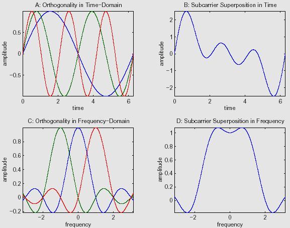
47 OFDM in frequency and time domains 47 n n Note orthogonality in both domains What is one OFDM symbol? Power Spectrum Fourier transform of symbol Channel B c single carrier frequency sub-carrier Sub-Carriers Amplitude 4 Carriers Spanning the Bandwidth of One Carrier Frequency time
48 OFDM Signal/Symbol 48 Df
49 OFDM Symbol 49 n One OFDM symbol lasts for say T s seconds n The symbol consists of the sum of the individual symbols from the many sub-carriers n Example: Consider QPSK on each carrier n In general n For N subchannels, the N samples of the i-th transmitted OFDM symbol can be written as Complex Number IFFT
50 Guard Time and Cyclic Prefix 50 n Guard time eliminates ISI if larger than expected delay spread occurs n If the guard time has no signal, intercarrier interference (ICI) may occur n ICI is like a cross talk between subcarriers n A cyclic prefix eliminates ICI n Ensures that delayed replicas of OFDM symbols always have integer number of cycles within the FFT interval n Maintains orthogonality between subcarriers n Cyclic prefix is removed at the receiver

51 OFDM Transmission basic system 51 n N consecutive complex symbols are converted into a group of N parallel data streams, which then are modulated over orthogonal subcarriers Channel Encoding Symbol Mapping Serial to Parallel N-Point IFFT Parallel To Serial Guard/CP Insertion Radio Channel + AWGN Channel Decoding Parallel to Serial Detector N-Point FFT Serial to Parallel Guard/CP Removal
52 Adaptive OFDM 52 H(f) frequency
53 Channel Partitioning for Multicarrier 53 Modulation n As the channel is frequency selective, it makes sense to split the channel into several smaller parts n Each smaller chunk is now an AWGN channel n Each AWGN channel provides a different SNR n Question: How do we allocate transmit powers/modulation schemes to each chunk? What is the most optimal? Noise PSD/ H(f) Allocation of power Water-filling algorithm Allocate more energy where the SNR is better!
54 Adaptive OFDM 54 n Improve channel capacity further n Change modulation scheme n Allocating bits/power per subcarrier according to the quality of each subchannel AOFDM Components Adaptive Loading/Allocation Algorithm + Set of Modulation Schemes + Channel Quality Estimator*
55 Adaptive Modulation 55 Set of Modulation Schemes No transmission (0 bits) BPSK (1 bit/symbol) QPSK (2 bits/symbol) 8-QAM (3 bits/symbol) 16-QAM (4 bits/symbol)
56 Adaptive Modulation on Parallel 56 Channels SNR (db) BW Efficiency 4 bits 3 bits 2 bits 1 bit Number of Subcarriers 16
57 Operation of Adaptive Algorithms 57 Based on optimal Water-Filling Power Distribution Channel Quality Estimator Adaptive Algorithm Channel Quality Information, e.g. SNR time Modulation Scheme Selection Subcarrier 1 Bits And Power Allocation Subcarrier 2 Subcarrier 3 + Subcarrier N
58 OFDM Based Wireless LANs IEEE a n Operates in the U-NII Band n , , and GHz n Provides multiple transmission modes/rates depending on channel conditions. n 6, 9, 12, 18, 24, 36, 48, and 54 Mbps n 4 digital modulations: BPSK, QPSK, 16-QAM, 64 QAM n Radio spectrum is divided into 8 separate segments/channels, 20 MHz each n 52 carriers (subchannels) per channel n Each subcarrier has bandwidth of ~300 khz n 48 for data modulation, and 4 for pilot signal
59 Recent Trends nmimo with OFDM n IEEE n, ac n Data rates greater than 100 Mbps nofdm for wide area data services n LTE and WiMax nother PHY technologies n UWB with OFDM n MC-CDMA
60 Revisiting Data Rates in Wireless 60 nhome A/V networks are expected to need 1-10 Gbps n Assuming a spectral efficiency of 1 bps/hz, we need at least 1 GHz of spectrum n Have ignored the effects of multipath fading n Brute force approach n May not meet the technology, regulatory and cost requirements ncan we increase the bps/hz in wireless systems?

61 Edholm s Law 61 n Phil Edholm n Nortel s CTO n Three Telecom Categories n Wireline n Nomadic (Portable) n Wireless (Mobile) Eventual convergence n Data rates increase exponentially n There is a predictable time lag between wireless and wireline systems Source: IEEE Spectrum - July 2004
62 How can we increase data rates? 62 n Traditional ways n Reduce the symbol duration n Needs larger bandwidth n Leads to a wideband channel and frequency selectivity - irreducible error rates n Increase the number of bits/symbol n Error rates increase with M for the same E b /N 0 n MIMO systems n There is no need to increase the bandwidth or power n But what are the limitations? n Use multiple transmit (Tx) and receive (Rx) antennas n Increases spectral efficiency to several tens of bps/hz
63 What is MIMO? 63 n So far we have considered Single Input Single Output or SISO systems n n Both transmitter and receiver have one antenna each Simplest form of transceiver architecture n Single input multiple-output (SIMO) systems n Receiver has multiple antennas n Multiple input multiple output (MIMO) systems n n Both transmitter and receiver have multiple antennas Strictly: Each antenna has its own RF chain (modulator, encoder and so on)
64 Performance enhancements due to 64 MIMO ndiversity gain n Ability to receive multiple copies of the signal with independent fading nspatial multiplexing gain n Send different information bits over different antennas and recover the information ninterference reduction n Reduce the region of interference thereby increasing capacity
Mobile & Wireless Networking. Lecture 2: Wireless Transmission (2/2)
") 192620010 Mobile & Wireless Networking Lecture 2: Wireless Transmission (2/2) [Schiller, Section 2.6 & 2.7] [Reader Part 1: OFDM: An architecture for the fourth generation] Geert Heijenk Outline of Lecture
192620010 Mobile & Wireless Networking Lecture 2: Wireless Transmission (2/2) [Schiller, Section 2.6 & 2.7] [Reader Part 1: OFDM: An architecture for the fourth generation] Geert Heijenk Outline of Lecture
Technical Aspects of LTE Part I: OFDM
 Technical Aspects of LTE Part I: OFDM By Mohammad Movahhedian, Ph.D., MIET, MIEEE m.movahhedian@mci.ir ITU regional workshop on Long-Term Evolution 9-11 Dec. 2013 Outline Motivation for LTE LTE Network
Part 3. Multiple Access Methods. p. 1 ELEC6040 Mobile Radio Communications, Dept. of E.E.E., HKU
 Part 3. Multiple Access Methods p. 1 ELEC6040 Mobile Radio Communications, Dept. of E.E.E., HKU Review of Multiple Access Methods Aim of multiple access To simultaneously support communications between
Lecture 13. Introduction to OFDM
 Lecture 13 Introduction to OFDM Ref: About-OFDM.pdf Orthogonal frequency division multiplexing (OFDM) is well-known to be effective against multipath distortion. It is a multicarrier communication scheme,
OFDMA and MIMO Notes
 OFDMA and MIMO Notes EE 442 Spring Semester Lecture 14 Orthogonal Frequency Division Multiplexing (OFDM) is a digital multi-carrier modulation technique extending the concept of single subcarrier modulation
S.D.M COLLEGE OF ENGINEERING AND TECHNOLOGY
 VISHVESHWARAIAH TECHNOLOGICAL UNIVERSITY S.D.M COLLEGE OF ENGINEERING AND TECHNOLOGY A seminar report on Orthogonal Frequency Division Multiplexing (OFDM) Submitted by Sandeep Katakol 2SD06CS085 8th semester
References. What is UMTS? UMTS Architecture
 1 References 2 Material Related to LTE comes from 3GPP LTE: System Overview, Product Development and Test Challenges, Agilent Technologies Application Note, 2008. IEEE Communications Magazine, February
Outline / Wireless Networks and Applications Lecture 7: Physical Layer OFDM. Frequency-Selective Radio Channel. How Do We Increase Rates?
 Page 1 Outline 18-452/18-750 Wireless Networks and Applications Lecture 7: Physical Layer OFDM Peter Steenkiste Carnegie Mellon University RF introduction Modulation and multiplexing Channel capacity Antennas
Simple Algorithm in (older) Selection Diversity. Receiver Diversity Can we Do Better? Receiver Diversity Optimization.
 Selection Diversity. Receiver Diversity Can we Do Better? Receiver Diversity Optimization.") 18-452/18-750 Wireless Networks and Applications Lecture 6: Physical Layer Diversity and Coding Peter Steenkiste Carnegie Mellon University Spring Semester 2017 http://www.cs.cmu.edu/~prs/wirelesss17/
18-452/18-750 Wireless Networks and Applications Lecture 6: Physical Layer Diversity and Coding Peter Steenkiste Carnegie Mellon University Spring Semester 2017 http://www.cs.cmu.edu/~prs/wirelesss17/
Page 1. Overview : Wireless Networks Lecture 9: OFDM, WiMAX, LTE
 Overview 18-759: Wireless Networks Lecture 9: OFDM, WiMAX, LTE Dina Papagiannaki & Peter Steenkiste Departments of Computer Science and Electrical and Computer Engineering Spring Semester 2009 http://www.cs.cmu.edu/~prs/wireless09/
Comparative Study of OFDM & MC-CDMA in WiMAX System
 IOSR Journal of Electronics and Communication Engineering (IOSR-JECE) e-issn: 2278-2834,p- ISSN: 2278-8735.Volume 9, Issue 1, Ver. IV (Jan. 2014), PP 64-68 Comparative Study of OFDM & MC-CDMA in WiMAX
Multiple Access Techniques
 Multiple Access Techniques EE 442 Spring Semester Lecture 13 Multiple Access is the use of multiplexing techniques to provide communication service to multiple users over a single channel. It allows for
Page 1. Outline : Wireless Networks Lecture 6: Final Physical Layer. Direct Sequence Spread Spectrum (DSSS) Spread Spectrum
 Spread Spectrum") Outline 18-759 : Wireless Networks Lecture 6: Final Physical Layer Peter Steenkiste Dina Papagiannaki Spring Semester 2009 http://www.cs.cmu.edu/~prs/wireless09/ Peter A. Steenkiste 1 RF introduction Modulation
Outline 18-759 : Wireless Networks Lecture 6: Final Physical Layer Peter Steenkiste Dina Papagiannaki Spring Semester 2009 http://www.cs.cmu.edu/~prs/wireless09/ Peter A. Steenkiste 1 RF introduction Modulation
Lecture 9: Spread Spectrum Modulation Techniques
 Lecture 9: Spread Spectrum Modulation Techniques Spread spectrum (SS) modulation techniques employ a transmission bandwidth which is several orders of magnitude greater than the minimum required bandwidth
Practical issue: Group definition. TSTE17 System Design, CDIO. Quadrature Amplitude Modulation (QAM) Components of a digital communication system
 Components of a digital communication system") 1 2 TSTE17 System Design, CDIO Introduction telecommunication OFDM principle How to combat ISI How to reduce out of band signaling Practical issue: Group definition Project group sign up list will be put
1 2 TSTE17 System Design, CDIO Introduction telecommunication OFDM principle How to combat ISI How to reduce out of band signaling Practical issue: Group definition Project group sign up list will be put
SC - Single carrier systems One carrier carries data stream
 Digital modulation SC - Single carrier systems One carrier carries data stream MC - Multi-carrier systems Many carriers are used for data transmission. Data stream is divided into sub-streams and each
EC 551 Telecommunication System Engineering. Mohamed Khedr
 EC 551 Telecommunication System Engineering Mohamed Khedr http://webmail.aast.edu/~khedr 1 Mohamed Khedr., 2008 Syllabus Tentatively Week 1 Week 2 Week 3 Week 4 Week 5 Week 6 Week 7 Week 8 Week 9 Week
Chapter 2 Overview - 1 -
 Chapter 2 Overview Part 1 (last week) Digital Transmission System Frequencies, Spectrum Allocation Radio Propagation and Radio Channels Part 2 (today) Modulation, Coding, Error Correction Part 3 (next
Orthogonal Frequency Division Multiplexing & Measurement of its Performance
 Available Online at www.ijcsmc.com International Journal of Computer Science and Mobile Computing A Monthly Journal of Computer Science and Information Technology IJCSMC, Vol. 5, Issue. 2, February 2016,
Multiple Access Schemes
 Multiple Access Schemes Dr Yousef Dama Faculty of Engineering and Information Technology An-Najah National University 2016-2017 Why Multiple access schemes Multiple access schemes are used to allow many
ALi Linear n-stage t ShiftRegister output tsequence
 PN CODE GENERATION (cont d) ALi Linear n-stage t ShiftRegister output tsequence Modulo-2 Adder h hn-1 h hn-2 h h2 h h1 X n-1 X n-2 X 1 X 0 Output Note: hi=1 represents a closed circuit; hi=0 represents
ECS455: Chapter 4 Multiple Access
 ECS455: Chapter 4 Multiple Access 4.4 DS/SS 1 Dr.Prapun Suksompong prapun.com/ecs455 Office Hours: BKD 3601-7 Tuesday 9:30-10:30 Tuesday 13:30-14:30 Thursday 13:30-14:30 Spread spectrum (SS) Historically
OFDM AS AN ACCESS TECHNIQUE FOR NEXT GENERATION NETWORK
 OFDM AS AN ACCESS TECHNIQUE FOR NEXT GENERATION NETWORK Akshita Abrol Department of Electronics & Communication, GCET, Jammu, J&K, India ABSTRACT With the rapid growth of digital wireless communication
CSC344 Wireless and Mobile Computing. Department of Computer Science COMSATS Institute of Information Technology
 CSC344 Wireless and Mobile Computing Department of Computer Science COMSATS Institute of Information Technology Wireless Physical Layer Concepts Part III Noise Error Detection and Correction Hamming Code
CS263: Wireless Communications and Sensor Networks
 CS263: Wireless Communications and Sensor Networks Matt Welsh Lecture 3: Antennas, Propagation, and Spread Spectrum September 30, 2004 2004 Matt Welsh Harvard University 1 Today's Lecture Antennas and
Lecture LTE (4G) -Technologies used in 4G and 5G. Spread Spectrum Communications
 -Technologies used in 4G and 5G. Spread Spectrum Communications") COMM 907: Spread Spectrum Communications Lecture 10 - LTE (4G) -Technologies used in 4G and 5G The Need for LTE Long Term Evolution (LTE) With the growth of mobile data and mobile users, it becomes essential
COMM 907: Spread Spectrum Communications Lecture 10 - LTE (4G) -Technologies used in 4G and 5G The Need for LTE Long Term Evolution (LTE) With the growth of mobile data and mobile users, it becomes essential
Multi-carrier Modulation and OFDM
 3/28/2 Multi-carrier Modulation and OFDM Prof. Luiz DaSilva dasilval@tcd.ie +353 896-366 Multi-carrier systems: basic idea Typical mobile radio channel is a fading channel that is flat or frequency selective
Orthogonal frequency division multiplexing (OFDM)
") Orthogonal frequency division multiplexing (OFDM) OFDM was introduced in 1950 but was only completed in 1960 s Originally grew from Multi-Carrier Modulation used in High Frequency military radio. Patent
Orthogonal frequency division multiplexing (OFDM) OFDM was introduced in 1950 but was only completed in 1960 s Originally grew from Multi-Carrier Modulation used in High Frequency military radio. Patent
Lecture 3: Wireless Physical Layer: Modulation Techniques. Mythili Vutukuru CS 653 Spring 2014 Jan 13, Monday
 Lecture 3: Wireless Physical Layer: Modulation Techniques Mythili Vutukuru CS 653 Spring 2014 Jan 13, Monday Modulation We saw a simple example of amplitude modulation in the last lecture Modulation how
Receiver Designs for the Radio Channel
 Receiver Designs for the Radio Channel COS 463: Wireless Networks Lecture 15 Kyle Jamieson [Parts adapted from C. Sodini, W. Ozan, J. Tan] Today 1. Delay Spread and Frequency-Selective Fading 2. Time-Domain
CDMA - QUESTIONS & ANSWERS
 CDMA - QUESTIONS & ANSWERS http://www.tutorialspoint.com/cdma/questions_and_answers.htm Copyright tutorialspoint.com 1. What is CDMA? CDMA stands for Code Division Multiple Access. It is a wireless technology
Orthogonal Frequency Division Multiplexing (OFDM) based Uplink Multiple Access Method over AWGN and Fading Channels
 based Uplink Multiple Access Method over AWGN and Fading Channels") Orthogonal Frequency Division Multiplexing (OFDM) based Uplink Multiple Access Method over AWGN and Fading Channels Prashanth G S 1 1Department of ECE, JNNCE, Shivamogga ---------------------------------------------------------------------***----------------------------------------------------------------------
Orthogonal Frequency Division Multiplexing (OFDM) based Uplink Multiple Access Method over AWGN and Fading Channels Prashanth G S 1 1Department of ECE, JNNCE, Shivamogga ---------------------------------------------------------------------***----------------------------------------------------------------------
Wireless Networks: An Introduction
 Wireless Networks: An Introduction Master Universitario en Ingeniería de Telecomunicación I. Santamaría Universidad de Cantabria Contents Introduction Cellular Networks WLAN WPAN Conclusions Wireless Networks:
Introduction to Wireless and Mobile Networking. Hung-Yu Wei g National Taiwan University
 Introduction to Wireless and Mobile Networking Lecture 3: Multiplexing, Multiple Access, and Frequency Reuse Hung-Yu Wei g National Taiwan University Multiplexing/Multiple Access Multiplexing Multiplexing
CSCD 433/533 Wireless Networks
 CSCD 433/533 Wireless Networks Lecture 8 Physical Layer, and 802.11 b,g,a,n Differences Winter 2017 1 Topics Spread Spectrum in General Differences between 802.11 b,g,a and n Frequency ranges Speed DSSS
Chapter 2 Overview - 1 -
 Chapter 2 Overview Part 1 (last week) Digital Transmission System Frequencies, Spectrum Allocation Radio Propagation and Radio Channels Part 2 (today) Modulation, Coding, Error Correction Part 3 (next
Lecture 3 Cellular Systems
 Lecture 3 Cellular Systems I-Hsiang Wang ihwang@ntu.edu.tw 3/13, 2014 Cellular Systems: Additional Challenges So far: focus on point-to-point communication In a cellular system (network), additional issues
S PG Course in Radio Communications. Orthogonal Frequency Division Multiplexing Yu, Chia-Hao. Yu, Chia-Hao 7.2.
 S-72.4210 PG Course in Radio Communications Orthogonal Frequency Division Multiplexing Yu, Chia-Hao chyu@cc.hut.fi 7.2.2006 Outline OFDM History OFDM Applications OFDM Principles Spectral shaping Synchronization
Spread Spectrum. Chapter 18. FHSS Frequency Hopping Spread Spectrum DSSS Direct Sequence Spread Spectrum DSSS using CDMA Code Division Multiple Access
 Spread Spectrum Chapter 18 FHSS Frequency Hopping Spread Spectrum DSSS Direct Sequence Spread Spectrum DSSS using CDMA Code Division Multiple Access Single Carrier The traditional way Transmitted signal
UNIK4230: Mobile Communications. Abul Kaosher
 UNIK4230: Mobile Communications Abul Kaosher abul.kaosher@nsn.com Multiple Access Multiple Access Introduction FDMA (Frequency Division Multiple Access) TDMA (Time Division Multiple Access) CDMA (Code
Wireless Medium Access Control and CDMA-based Communication Lesson 16 Orthogonal Frequency Division Medium Access (OFDM)
") Wireless Medium Access Control and CDMA-based Communication Lesson 16 Orthogonal Frequency Division Medium Access (OFDM) 1 4G File transfer at 10 Mbps High resolution 1024 1920 pixel hi-vision picture
Wireless Medium Access Control and CDMA-based Communication Lesson 16 Orthogonal Frequency Division Medium Access (OFDM) 1 4G File transfer at 10 Mbps High resolution 1024 1920 pixel hi-vision picture
An OFDM Transmitter and Receiver using NI USRP with LabVIEW
 An OFDM Transmitter and Receiver using NI USRP with LabVIEW Saba Firdose, Shilpa B, Sushma S Department of Electronics & Communication Engineering GSSS Institute of Engineering & Technology For Women Abstract-
Frame Synchronization Symbols for an OFDM System
 Frame Synchronization Symbols for an OFDM System Ali A. Eyadeh Communication Eng. Dept. Hijjawi Faculty for Eng. Technology Yarmouk University, Irbid JORDAN aeyadeh@yu.edu.jo Abstract- In this paper, the
Bit Error Rate Performance Evaluation of Various Modulation Techniques with Forward Error Correction Coding of WiMAX
 Bit Error Rate Performance Evaluation of Various Modulation Techniques with Forward Error Correction Coding of WiMAX Amr Shehab Amin 37-20200 Abdelrahman Taha 31-2796 Yahia Mobasher 28-11691 Mohamed Yasser
Field Experiments of 2.5 Gbit/s High-Speed Packet Transmission Using MIMO OFDM Broadband Packet Radio Access
 NTT DoCoMo Technical Journal Vol. 8 No.1 Field Experiments of 2.5 Gbit/s High-Speed Packet Transmission Using MIMO OFDM Broadband Packet Radio Access Kenichi Higuchi and Hidekazu Taoka A maximum throughput
Decrease Interference Using Adaptive Modulation and Coding
 International Journal of Computer Networks and Communications Security VOL. 3, NO. 9, SEPTEMBER 2015, 378 383 Available online at: www.ijcncs.org E-ISSN 2308-9830 (Online) / ISSN 2410-0595 (Print) Decrease
Chapter 2: Wireless Transmission. Mobile Communications. Spread spectrum. Multiplexing. Modulation. Frequencies. Antenna. Signals
 Mobile Communications Chapter 2: Wireless Transmission Frequencies Multiplexing Signals Spread spectrum Antenna Modulation Signal propagation Cellular systems Prof. Dr.-Ing. Jochen Schiller, http://www.jochenschiller.de/
Optimal Number of Pilots for OFDM Systems
 IOSR Journal of Electronics and Communication Engineering (IOSR-JECE) e-issn: 2278-2834,p- ISSN: 2278-8735.Volume 8, Issue 6 (Nov. - Dec. 2013), PP 25-31 Optimal Number of Pilots for OFDM Systems Onésimo
Implementation and Comparative analysis of Orthogonal Frequency Division Multiplexing (OFDM) Signaling Rashmi Choudhary
 Signaling Rashmi Choudhary") Implementation and Comparative analysis of Orthogonal Frequency Division Multiplexing (OFDM) Signaling Rashmi Choudhary M.Tech Scholar, ECE Department,SKIT, Jaipur, Abstract Orthogonal Frequency Division
Implementation and Comparative analysis of Orthogonal Frequency Division Multiplexing (OFDM) Signaling Rashmi Choudhary M.Tech Scholar, ECE Department,SKIT, Jaipur, Abstract Orthogonal Frequency Division
Chapter 7 Multiple Division Techniques for Traffic Channels
 Introduction to Wireless & Mobile Systems Chapter 7 Multiple Division Techniques for Traffic Channels Outline Introduction Concepts and Models for Multiple Divisions Frequency Division Multiple Access
4x4 Time-Domain MIMO encoder with OFDM Scheme in WIMAX Context
 4x4 Time-Domain MIMO encoder with OFDM Scheme in WIMAX Context Mohamed.Messaoudi 1, Majdi.Benzarti 2, Salem.Hasnaoui 3 Al-Manar University, SYSCOM Laboratory / ENIT, Tunisia 1 messaoudi.jmohamed@gmail.com,
Performance of Orthogonal Frequency Division Multiplexing System Based on Mobile Velocity and Subcarrier
 Journal of Computer Science 6 (): 94-98, 00 ISSN 549-3636 00 Science Publications Performance of Orthogonal Frequency Division Multiplexing System ased on Mobile Velocity and Subcarrier Zulkeflee in halidin
Survey on Effective OFDM Technology for 4G
 Survey on Effective OFDM Technology for 4G Kanchan Vijay Patil, 2 R D Patane, Lecturer, 2 Professor, Electronics and Telecommunication, ARMIET, Shahpur, India 2 Terna college of engineering, Nerul, India
Access Methods and Spectral Efficiency
 Access Methods and Spectral Efficiency Yousef Dama An-Najah National University Mobile Communications Access methods SDMA/FDMA/TDMA SDMA (Space Division Multiple Access) segment space into sectors, use
Wireless Physical Layer Concepts: Part III
 Wireless Physical Layer Concepts: Part III Raj Jain Professor of CSE Washington University in Saint Louis Saint Louis, MO 63130 Jain@cse.wustl.edu These slides are available on-line at: http://www.cse.wustl.edu/~jain/cse574-08/
OFDMA PHY for EPoC: a Baseline Proposal. Andrea Garavaglia and Christian Pietsch Qualcomm PAGE 1
 OFDMA PHY for EPoC: a Baseline Proposal Andrea Garavaglia and Christian Pietsch Qualcomm PAGE 1 Supported by Jorge Salinger (Comcast) Rick Li (Cortina) Lup Ng (Cortina) PAGE 2 Outline OFDM: motivation
Advanced 3G & 4G Wireless Communication Prof. Aditya K. Jagannatham Department of Electrical Engineering Indian Institute of Technology, Kanpur
 Advanced 3G & 4G Wireless Communication Prof. Aditya K. Jagannatham Department of Electrical Engineering Indian Institute of Technology, Kanpur Lecture - 30 OFDM Based Parallelization and OFDM Example
1. INTRODUCTION II. SPREADING USING WALSH CODE. International Journal of Advanced Networking & Applications (IJANA) ISSN:
 ISSN:") Analysis of DWT OFDM using Rician Channel and Comparison with ANN based OFDM Geeta S H1, Smitha B2, Shruthi G, Shilpa S G4 Department of Computer Science and Engineering, DBIT, Bangalore, Visvesvaraya
Analysis of DWT OFDM using Rician Channel and Comparison with ANN based OFDM Geeta S H1, Smitha B2, Shruthi G, Shilpa S G4 Department of Computer Science and Engineering, DBIT, Bangalore, Visvesvaraya
Point-to-Point Communications
 Point-to-Point Communications Key Aspects of Communication Voice Mail Tones Alphabet Signals Air Paper Media Language English/Hindi English/Hindi Outline of Point-to-Point Communication 1. Signals basic
RADIO LINK ASPECT OF GSM
 RADIO LINK ASPECT OF GSM The GSM spectral allocation is 25 MHz for base transmission (935 960 MHz) and 25 MHz for mobile transmission With each 200 KHz bandwidth, total number of channel provided is 125
Performance Evaluation of STBC-OFDM System for Wireless Communication
 Performance Evaluation of STBC-OFDM System for Wireless Communication Apeksha Deshmukh, Prof. Dr. M. D. Kokate Department of E&TC, K.K.W.I.E.R. College, Nasik, apeksha19may@gmail.com Abstract In this paper
Level 6 Graduate Diploma in Engineering Wireless and mobile communications
 9210-119 Level 6 Graduate Diploma in Engineering Wireless and mobile communications Sample Paper You should have the following for this examination one answer book non-programmable calculator pen, pencil,
SHIV SHAKTI International Journal of in Multidisciplinary and Academic Research (SSIJMAR) Vol. 3, No. 4, August-September (ISSN )
 Vol. 3, No. 4, August-September (ISSN )") SHIV SHAKTI International Journal of in Multidisciplinary and Academic Research (SSIJMAR) Vol. 3, No. 4, August-September (ISSN 2278 5973) Orthogonal Frequency Division Multiplexing: Issues and Applications
SHIV SHAKTI International Journal of in Multidisciplinary and Academic Research (SSIJMAR) Vol. 3, No. 4, August-September (ISSN 2278 5973) Orthogonal Frequency Division Multiplexing: Issues and Applications
Chapter 7. Multiple Division Techniques
 Chapter 7 Multiple Division Techniques 1 Outline Frequency Division Multiple Access (FDMA) Division Multiple Access (TDMA) Code Division Multiple Access (CDMA) Comparison of FDMA, TDMA, and CDMA Walsh
SEN366 (SEN374) (Introduction to) Computer Networks
 (Introduction to) Computer Networks") SEN366 (SEN374) (Introduction to) Computer Networks Prof. Dr. Hasan Hüseyin BALIK (8 th Week) Cellular Wireless Network 8.Outline Principles of Cellular Networks Cellular Network Generations LTE-Advanced
SEN366 (SEN374) (Introduction to) Computer Networks Prof. Dr. Hasan Hüseyin BALIK (8 th Week) Cellular Wireless Network 8.Outline Principles of Cellular Networks Cellular Network Generations LTE-Advanced
Performance Analysis of OFDM for Different Digital Modulation Schemes using Matlab Simulation
 J. Bangladesh Electron. 10 (7-2); 7-11, 2010 Performance Analysis of OFDM for Different Digital Modulation Schemes using Matlab Simulation Md. Shariful Islam *1, Md. Asek Raihan Mahmud 1, Md. Alamgir Hossain
Multiple Access Techniques for Wireless Communications
 Multiple Access Techniques for Wireless Communications Contents 1. Frequency Division Multiple Access (FDMA) 2. Time Division Multiple Access (TDMA) 3. Code Division Multiple Access (CDMA) 4. Space Division
Multiplexing Module W.tra.2
 Multiplexing Module W.tra.2 Dr.M.Y.Wu@CSE Shanghai Jiaotong University Shanghai, China Dr.W.Shu@ECE University of New Mexico Albuquerque, NM, USA 1 Multiplexing W.tra.2-2 Multiplexing shared medium at
ECE 476/ECE 501C/CS Wireless Communication Systems Winter Lecture 9: Multiple Access, GSM, and IS-95
 ECE 476/ECE 501C/CS 513 - Wireless Communication Systems Winter 2003 Lecture 9: Multiple Access, GSM, and IS-95 Outline: Two other important issues related to multiple access space division with smart
OFDM Systems For Different Modulation Technique
 Computing For Nation Development, February 08 09, 2008 Bharati Vidyapeeth s Institute of Computer Applications and Management, New Delhi OFDM Systems For Different Modulation Technique Mrs. Pranita N.
EENG473 Mobile Communications Module 3 : Week # (12) Mobile Radio Propagation: Small-Scale Path Loss
 Mobile Radio Propagation: Small-Scale Path Loss") EENG473 Mobile Communications Module 3 : Week # (12) Mobile Radio Propagation: Small-Scale Path Loss Introduction Small-scale fading is used to describe the rapid fluctuation of the amplitude of a radio
EENG473 Mobile Communications Module 3 : Week # (12) Mobile Radio Propagation: Small-Scale Path Loss Introduction Small-scale fading is used to describe the rapid fluctuation of the amplitude of a radio
2: Diversity. 2. Diversity. Some Concepts of Wireless Communication
 2. Diversity 1 Main story Communication over a flat fading channel has poor performance due to significant probability that channel is in a deep fade. Reliability is increased by providing more resolvable
Planning of LTE Radio Networks in WinProp
 Planning of LTE Radio Networks in WinProp AWE Communications GmbH Otto-Lilienthal-Str. 36 D-71034 Böblingen mail@awe-communications.com Issue Date Changes V1.0 Nov. 2010 First version of document V2.0
CDMA Principle and Measurement
 CDMA Principle and Measurement Concepts of CDMA CDMA Key Technologies CDMA Air Interface CDMA Measurement Basic Agilent Restricted Page 1 Cellular Access Methods Power Time Power Time FDMA Frequency Power
EE359 Lecture 18 Outline
 EE359 Lecture 18 Outline Announcements HW due Fri; last HW posted, due Friday 12/9 at 4 pm (no late HWs) MIMO decoder supplemental handout posted Lectures net week are Monday 12/5 12-1:20 (Thornton 102
BER Analysis for MC-CDMA
 BER Analysis for MC-CDMA Nisha Yadav 1, Vikash Yadav 2 1,2 Institute of Technology and Sciences (Bhiwani), Haryana, India Abstract: As demand for higher data rates is continuously rising, there is always
SPREAD SPECTRUM (SS) SIGNALS FOR DIGITAL COMMUNICATIONS
 SIGNALS FOR DIGITAL COMMUNICATIONS") Dr. Ali Muqaibel SPREAD SPECTRUM (SS) SIGNALS FOR DIGITAL COMMUNICATIONS VERSION 1.1 Dr. Ali Hussein Muqaibel 1 Introduction Narrow band signal (data) In Spread Spectrum, the bandwidth W is much greater
Dr. Ali Muqaibel SPREAD SPECTRUM (SS) SIGNALS FOR DIGITAL COMMUNICATIONS VERSION 1.1 Dr. Ali Hussein Muqaibel 1 Introduction Narrow band signal (data) In Spread Spectrum, the bandwidth W is much greater
With a lot of material from Rich Nicholls, CTL/RCL and Kurt Sundstrom, of unknown whereabouts
 Signal Processing for OFDM Communication Systems Eric Jacobsen Minister of Algorithms, Intel Labs Communication Technology Laboratory/ Radio Communications Laboratory July 29, 2004 With a lot of material
MITIGATING CARRIER FREQUENCY OFFSET USING NULL SUBCARRIERS
 International Journal on Intelligent Electronic System, Vol. 8 No.. July 0 6 MITIGATING CARRIER FREQUENCY OFFSET USING NULL SUBCARRIERS Abstract Nisharani S N, Rajadurai C &, Department of ECE, Fatima
A Research Concept on Bit Rate Detection using Carrier offset through Analysis of MC-CDMA SYSTEM
 Available Online at www.ijcsmc.com International Journal of Computer Science and Mobile Computing A Monthly Journal of Computer Science and Information Technology ISSN 2320 088X IMPACT FACTOR: 5.258 IJCSMC,
SNS COLLEGE OF ENGINEERING COIMBATORE DEPARTMENT OF INFORMATION TECHNOLOGY QUESTION BANK
 SNS COLLEGE OF ENGINEERING COIMBATORE 641107 DEPARTMENT OF INFORMATION TECHNOLOGY QUESTION BANK EC6801 WIRELESS COMMUNICATION UNIT-I WIRELESS CHANNELS PART-A 1. What is propagation model? 2. What are the
Fundamentals of OFDM Communication Technology
 Fundamentals of OFDM Communication Technology Fuyun Ling Rev. 1, 04/2013 1 Outline Fundamentals of OFDM An Introduction OFDM System Design Considerations Key OFDM Receiver Functional Blocks Example: LTE
Introduction to WiMAX Dr. Piraporn Limpaphayom
 Introduction to WiMAX Dr. Piraporn Limpaphayom 1 WiMAX : Broadband Wireless 2 1 Agenda Introduction to Broadband Wireless Overview of WiMAX and Application WiMAX: PHY layer Broadband Wireless Channel OFDM
Wireless Communication: Concepts, Techniques, and Models. Hongwei Zhang
 Wireless Communication: Concepts, Techniques, and Models Hongwei Zhang http://www.cs.wayne.edu/~hzhang Outline Digital communication over radio channels Channel capacity MIMO: diversity and parallel channels
UNIFIED DIGITAL AUDIO AND DIGITAL VIDEO BROADCASTING SYSTEM USING ORTHOGONAL FREQUENCY DIVISION MULTIPLEXING (OFDM) SYSTEM
 SYSTEM") UNIFIED DIGITAL AUDIO AND DIGITAL VIDEO BROADCASTING SYSTEM USING ORTHOGONAL FREQUENCY DIVISION MULTIPLEXING (OFDM) SYSTEM 1 Drakshayini M N, 2 Dr. Arun Vikas Singh 1 drakshayini@tjohngroup.com, 2 arunsingh@tjohngroup.com
UNIFIED DIGITAL AUDIO AND DIGITAL VIDEO BROADCASTING SYSTEM USING ORTHOGONAL FREQUENCY DIVISION MULTIPLEXING (OFDM) SYSTEM 1 Drakshayini M N, 2 Dr. Arun Vikas Singh 1 drakshayini@tjohngroup.com, 2 arunsingh@tjohngroup.com
2.
 PERFORMANCE ANALYSIS OF STBC-MIMO OFDM SYSTEM WITH DWT & FFT Shubhangi R Chaudhary 1,Kiran Rohidas Jadhav 2. Department of Electronics and Telecommunication Cummins college of Engineering for Women Pune,
Wireless Transmission & Media Access
 Wireless Transmission & Media Access Signals and Signal Propagation Multiplexing Modulation Media Access 1 Significant parts of slides are based on original material by Prof. Dr.-Ing. Jochen Schiller,
Performance Evaluation of Wireless Communication System Employing DWT-OFDM using Simulink Model
 Performance Evaluation of Wireless Communication System Employing DWT-OFDM using Simulink Model M. Prem Anand 1 Rudrashish Roy 2 1 Assistant Professor 2 M.E Student 1,2 Department of Electronics & Communication
Major Leaps in Evolution of IEEE WLAN Technologies
 Major Leaps in Evolution of IEEE 802.11 WLAN Technologies Thomas A. KNEIDEL Rohde & Schwarz Product Management Mobile Radio Tester WLAN Mayor Player in Wireless Communications Wearables Smart Homes Smart
Analysis of Interference & BER with Simulation Concept for MC-CDMA
 IOSR Journal of Electronics and Communication Engineering (IOSR-JECE) e-issn: 2278-2834,p- ISSN: 2278-8735.Volume 9, Issue 4, Ver. IV (Jul - Aug. 2014), PP 46-51 Analysis of Interference & BER with Simulation
Channel Estimation in Multipath fading Environment using Combined Equalizer and Diversity Techniques
 International Journal of Scientific & Engineering Research Volume3, Issue 1, January 2012 1 Channel Estimation in Multipath fading Environment using Combined Equalizer and Diversity Techniques Deepmala
Spread Spectrum (SS) is a means of transmission in which the signal occupies a
 is a means of transmission in which the signal occupies a") SPREAD-SPECTRUM SPECTRUM TECHNIQUES: A BRIEF OVERVIEW SS: AN OVERVIEW Spread Spectrum (SS) is a means of transmission in which the signal occupies a bandwidth in excess of the minimum necessary to send
SPREAD-SPECTRUM SPECTRUM TECHNIQUES: A BRIEF OVERVIEW SS: AN OVERVIEW Spread Spectrum (SS) is a means of transmission in which the signal occupies a bandwidth in excess of the minimum necessary to send
CHAPTER 2. Instructor: Mr. Abhijit Parmar Course: Mobile Computing and Wireless Communication ( )
") CHAPTER 2 Instructor: Mr. Abhijit Parmar Course: Mobile Computing and Wireless Communication (2170710) Syllabus Chapter-2.4 Spread Spectrum Spread Spectrum SS was developed initially for military and intelligence
CHAPTER 2 Instructor: Mr. Abhijit Parmar Course: Mobile Computing and Wireless Communication (2170710) Syllabus Chapter-2.4 Spread Spectrum Spread Spectrum SS was developed initially for military and intelligence
Chapter 1 Acknowledgment:
 Chapter 1 Acknowledgment: This material is based on the slides formatted by Dr Sunilkumar S. Manvi and Dr Mahabaleshwar S. Kakkasageri, the authors of the textbook: Wireless and Mobile Networks, concepts
Spread Spectrum: Definition
 Spread Spectrum: Definition refers to the expansion of signal bandwidth, by several orders of magnitude in some cases, which occurs when a key is attached to the communication channel an RF communications
Lecture 7: Centralized MAC protocols. Mythili Vutukuru CS 653 Spring 2014 Jan 27, Monday
 Lecture 7: Centralized MAC protocols Mythili Vutukuru CS 653 Spring 2014 Jan 27, Monday Centralized MAC protocols Previous lecture contention based MAC protocols, users decide who transmits when in a decentralized
ORTHOGONAL frequency division multiplexing (OFDM)
") 144 IEEE TRANSACTIONS ON BROADCASTING, VOL. 51, NO. 1, MARCH 2005 Performance Analysis for OFDM-CDMA With Joint Frequency-Time Spreading Kan Zheng, Student Member, IEEE, Guoyan Zeng, and Wenbo Wang, Member,
144 IEEE TRANSACTIONS ON BROADCASTING, VOL. 51, NO. 1, MARCH 2005 Performance Analysis for OFDM-CDMA With Joint Frequency-Time Spreading Kan Zheng, Student Member, IEEE, Guoyan Zeng, and Wenbo Wang, Member,
ANALYSIS OF BER AND SEP OF QPSK SIGNAL FOR MULTIPLE ANENNAS
 ANALYSIS OF BER AND SEP OF QPSK SIGNAL FOR MULTIPLE ANENNAS Suganya.S 1 1 PG scholar, Department of ECE A.V.C College of Engineering Mannampandhal, India Karthikeyan.T 2 2 Assistant Professor, Department
Data and Computer Communications. Tenth Edition by William Stallings
 Data and Computer Communications Tenth Edition by William Stallings Data and Computer Communications, Tenth Edition by William Stallings, (c) Pearson Education - 2013 CHAPTER 10 Cellular Wireless Network
CHAPTER 3 ADAPTIVE MODULATION TECHNIQUE WITH CFO CORRECTION FOR OFDM SYSTEMS
 44 CHAPTER 3 ADAPTIVE MODULATION TECHNIQUE WITH CFO CORRECTION FOR OFDM SYSTEMS 3.1 INTRODUCTION A unique feature of the OFDM communication scheme is that, due to the IFFT at the transmitter and the FFT