INSTITUTE OF AERONAUTICAL ENGINEERING
|
|
|
- Alison Chapman
- 5 years ago
- Views:
Transcription

1 POWER POINT PRESENTATION ON ELECTRICAL MACHINES - II II B. Tech II semester (JNTUH-R15) Mr. K DEVENDER REDDY, Assistant Professor ELECTRICAL AND ELECTRONICS ENGINEERING INSTITUTE OF AERONAUTICAL ENGINEERING DUNDIGAL, HYDERABAD
2 UNIT -I Single-Phase Transformers
3 Single-Phase Transformers Objectives: Discuss the different types of transformers. List transformer symbols and formulas. Discuss polarity markings.

4 Single-Phase Transformers A transformer is a magnetically operated machine. All values of a transformer are proportional to its turns ratio.
5 Single-Phase Transformers The primary winding is connected to the incoming power supply. The secondary winding is connected to the driven load.

6 Single-Phase Transformers This is an isolation transformer. The secondary winding is physically and electrically isolated from the primary winding.

7 Single-Phase Transformers The two windings of an isolation transformer are linked together by the magnetic field.

8 Single-Phase Transformers The isolation transformer greatly reduces voltage spikes.

9 Single-Phase Transformers Basic construction of an isolation transformer.
10 Single-Phase Transformers Each set of windings (primary and secondary) is formed from loops of wire wrapped around the core. Each loop of wire is called a turn. The ratio of the primary and secondary voltages is determined by the ratio of the number of turns in the primary and secondary windings. The volts-per-turn ratio is the same on both the primary and secondary windings.
11 Single-Phase Transformers Transformer Symbols N P = number of turns in the primary N S = number of turns in the secondary E P = voltage of the primary E S = voltage of the secondary I P = current in the primary I S = current in the secondary
12 Single-Phase Transformers Transformer Formulas E P / E S = N P / N S E P x N S = E S x N P E P x I P = E S x I S N P x I P = N S x I S

13 Single-Phase Transformers The distribution transformer is a common type of isolation transformer. This transformer changes the high voltage from the power company to the common 40/10 V.
14 Single-Phase Transformers The control transformer is another common type of isolation transformer. This transformer reduces high voltage to the value needed by control circuits.

15 Single-Phase Transformers Polarity dots are placed on transformer schematics to indicate points that have the same polarity at the same time.
16 Single-Phase Transformers Review: 1. All values of voltage, current, and impedance in a transformer are proportional to the turns ratio.. The primary winding of a transformer is connected to the source voltage. 3. The secondary winding is connected to the load.
17 Single-Phase Transformers Review: 4. An isolation transformer has its primary and secondary voltage electrically and mechanically separated. 5. Isolation transformers help filter voltage and current spikes. 6. Polarity dots are often added to schematic diagrams to indicate transformer polarity.
18 Transformer Regulation Loading changes the output voltage of a transformer. Definition of % Regulation V noload V V load load *100 V no-load =RMS voltage across the load terminals without load V load = RMS voltage across the load terminals with a specified load

19 ' 0 ' 1 0; max. 0 eq eq eq eq or imum when is V Clearly Z I V V Maximum Transformer Regulation
20 Transformer Losses and Efficiency Transformer Losses Core/Iron Loss =V 1 / R c1 Copper Loss = I 1 R 1 + I R Definition of % efficiency V VI Cos Losses V I Cos V I Cos *100 1 / Rc1 I1 R1 I R VI Cos V V 1 / Rc1 I Req VI Cos Cos I Cos = load power factor *100 *100 Transformer 0
21 Maximum Transformer Efficiency The efficiency varies as with respect to independent quantities namely, current and power factor Thus at any particular power factor, the efficiency is maximum if core loss = copper loss.this can be obtained by differentiating the expression of efficiency with respect to I assuming power factor, and all the voltages constant. At any particular I maximum efficiency happens at unity power factor. This can be obtained by differentiating the expression of efficiency with respect to power factor, and assuming I and all the voltages constant. Maximum efficiency happens when both these conditions are satisfied. Transformer 1
22 Maximum efficiency point 100 pf=1 pf= 0.8 pf= At this load current core loss = copper loss % full load current Transformer
23 Transformer Equivalent circuit (1) I1 INL E1 E I Transformer 3
24 Transformer Equivalent circuit () I I1 INL Transformer 4
25 Transformer Equivalent circuit (3) I1 I INL Transformer 5
26 Transformer Equivalent circuit (4) I1 INL I' Transformer 6

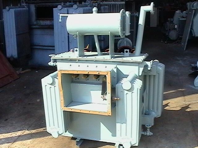
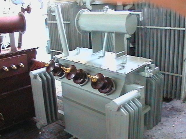
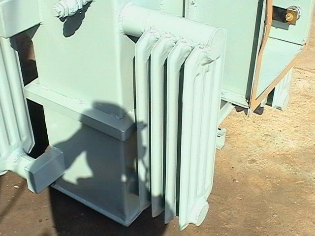
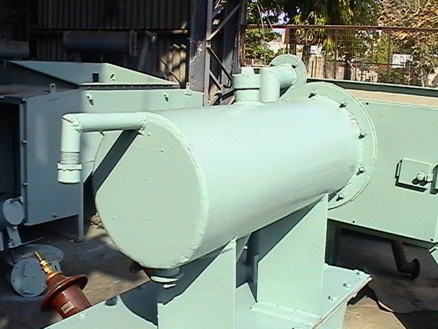
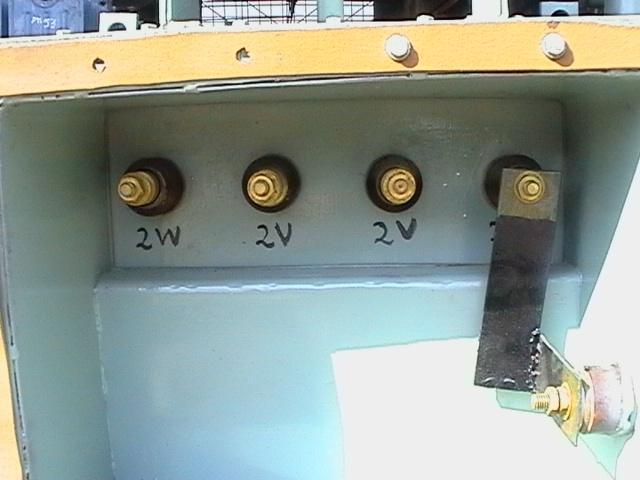
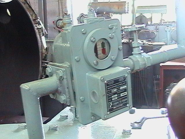
27 PARTS OF TRANSFORMER MAIN TANK RADIATORS CONSERVATOR EXPLOSION VENT LIFTING LUGS AIR RELEASE PLUG OIL LEVEL INDICATOR TAP CHANGER WHEELS HV/LV BUSHINGS FILTER VALVES OIL FILLING PLUG DRAIN PLUG CABLE BOX
28
29
30
31
32
33
34
35
36
37
38 UNIT TESTING OF TRANSFORMERS
39 TESTING OF TRANSFORMER Testing of single phase Transformers OC Test SC test Sumpner s Test or Back to Back Test
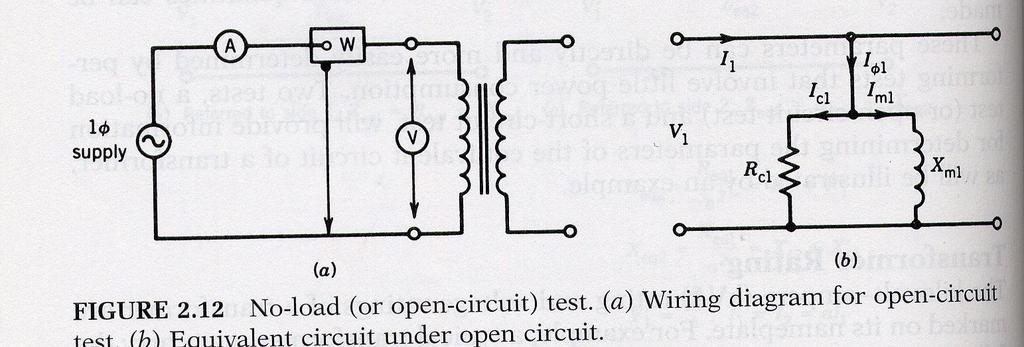
40 Open circuit Test It is used to determine L m1 (X m1 )and R c1 Usually performed on the low voltage side The test is performed at rated voltage and frequency under no load This test gives the values of core losses in a transformer Transformer 40
41
42 Woc= Core loss of the transformer From the data Cosø= Woc/(Voc*Ioc) Iw=IocCosø Ių = Ioc Sinø Rcl=Voc/Iw Xml=Voc/I ų
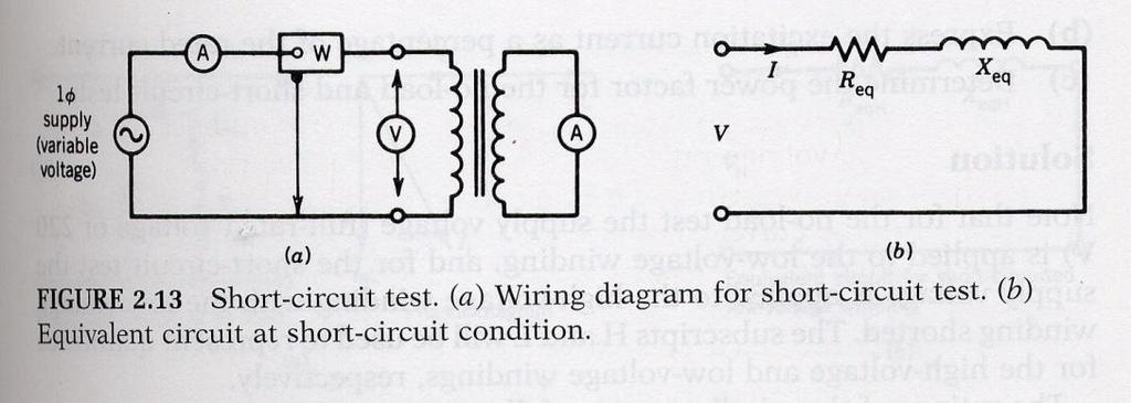
43 Short circuit Test It is used to determine Ll p (X eq ) and R p (R eq ) Usually performed on the high voltage side This test is performed at reduced voltage and rated frequency with the output of the low voltage winding short circuited such that rated current flows on the high voltage side. This test gives copper loss of the transformer. Transformer 43
44
45 Wsc= copper losses of the transformer. Zeq=Vsc/Isc Req=Wsc/Isc² Xeq=sqrt(Zeq²-Req²)
46 Efficiency of the transformer Ŋ = output Power/ Input power Ŋ = XVICosø/(XVICosø + Pc +x²pcu)

47 Sumpner s test or back to back test on set of transformers From this test Losses and Efficiency of the two transformers can be determined

48 Parallel operation of transformers Wrong connections give circulating between the windings that can destroy transformers. Transformer 48
49 To connect the transformers in parallel the following conditions must be satisfied i. Transformers must be of same rating. ii. Transformers should have the same phase sequence. iii. voltage ratio must be same. iv. Per unit impedence of the transformers must be same.
50 UNIT-III AUTO AND POLY PHASE TRANSFORMERS
51 Autotransformer Primary and secondary on the same winding. Therefore there is no galvanic isolation. Transformer 51
52 Features of Autotransformer Lower leakage Lower losses Lower magnetizing current Increase kva rating No galvanic Isolation Transformer 5
53 Review of balanced three phase circui Two possible configurations: Star (Y) and delta () Star has neutral, delta does not Transformer 53
54 Star (Y) connection Line current is same as phase current Line-Line voltage is 3 phase-neutral voltage Power is given by 3 V L-L I L cos or 3V ph I ph cos Transformer 54
55 Delta () connection Line-Line voltage is same as phase voltage Line current is 3 phase current Power is given by 3 V L-L I L cos or 3V ph I ph cos Transformer 55

56 Typical three phase transformer connections Transformer 56
57 Other possible three phase transformer Connections Y- zigzag - zigzag Open Delta or V Scott or T Transformer 57
58 How are three phase transformers made? Either by having three single phase transformers connected as three phase banks. Or by having coils mounted on a single core with multiple limbs The bank configuration is better from repair perspective, whereas the single three phase unit will cost less,occupy less space, weighs less and is more efficient Transformer 58

59 Phase-shift between line-line voltages in transformers Transformer 59
60 Vector grouping of transformers Depending upon the phase shift of line-neutral voltages between primary and secondary; transformers are grouped. This is done for ease of paralleling. Usually transformers between two different groups should not be paralleled. Group 1 :zero phase displacement (Yy0, Dd0,Dz0) Group :180 0 phase displacement (Yy6, Dd6,Dz6) Group 3 : 30 0 lag phase displacement (Dy1, Yd1,Yz1) Group 4 : 30 0 lead phase displacement (Dy11, Yd11,Yz11) (Y=Y; D= ; z=zigzag) Transformer 60

61 Calculation involving 3-ph transformers Transformer 61

62 An example involving 3-ph transformers Transformer 6

63 Open delta or V connection Transformer 63
64 Open delta or V connection Power from winding ab is P ab =V ab I a cos(30 0 +) Power from winding bc is P cb =V cb I c cos(30 0 -) Therefore total power is =V L-L I L cos30 0 cos or 57.7% of total power from 3 phases Transformer 64
65 Harmonics in 3- Transformer Banks In absence of neutral connection in a Y-Y transformers 3 rd harmonic current cannot flow This causes 3 rd harmonic distortion in the phase voltages (both primary and secondary) but not line-line voltages, as 3 rd harmonic voltages get cancelled out in line-line connections Remedy is either of the following : a) Neutral connections, b) Tertiary winding c) Use zigzag secondary d) Use stardelta or delta-delta type of transformers. a) The phenomenon is explained using a star-delta transformer. Transformer 65
")
66 Harmonics in 3- Transformer Banks() Transformer 66

 67")
67 Harmonics in 3- Transformer Banks(3) Transformer 67

68 Three-Phase Transformers Sine wave distortion caused by harmonics.

69 UNIT-4 POLY-PHASE INDUCTION MOTORS
70 Introduction Three-phase induction motors are the most common and frequently encountered machines in industry simple design, rugged, low-price, easy maintenance wide range of power ratings: fractional horsepower to 10 MW run essentially as constant speed from no-load to full load Its speed depends on the frequency of the power source not easy to have variable speed control requires a variable-frequency power-electronic drive for optimal speed control

71 Construction An induction motor has two main parts a stationary stator consisting of a steel frame that supports a hollow, cylindrical core core, constructed from stacked laminations (why?), having a number of evenly spaced slots, providing the space for the stator winding Stator of IM
72 Construction a revolving rotor composed of punched laminations, stacked to create a series of rotor slots, providing space for the rotor winding one of two types of rotor windings conventional 3-phase windings made of insulated wire (wound-rotor)» similar to the winding on the stator aluminum bus bars shorted together at the ends by two aluminum rings, forming a squirrel-cage shaped circuit (squirrel-cage) Two basic design types depending on the rotor design squirrel-cage: conducting bars laid into slots and shorted at both ends by shorting rings. wound-rotor: complete set of three-phase windings exactly as the stator. Usually Y-connected, the ends of the three rotor wires are connected to 3 slip rings on the rotor shaft. In this way, the rotor circuit is accessible.


73 Construction Squirrel cage rotor Wound rotor Notice the slip rings

74 Construction Slip rings Cutaway in a typical woundrotor IM. Notice the brushes and the slip rings Brushe s

75 Rotating Magnetic Field Balanced three phase windings, i.e. mechanically displaced 10 degrees form each other, fed by balanced three phase source A rotating magnetic field with constant magnitude is produced, rotating with a speed n sync 10 f e P rpm Where f e is the supply frequency and P is the no. of poles and n sync is called the synchronous speed in rpm (revolutions per minute)
76 Synchronous speed P 50 Hz 60 Hz
77 Rotating Magnetic Field

78 Rotating Magnetic Field
79 Rotating Magnetic Field B ( t) B ( t) B ( t) B ( t) net a b c B sin( t) 0 B sin( t 10 ) 10 B sin( t 40) 40 B M M M M sin( t)ˆ x 3 [0.5B sin( 10 )] ˆ M t x[ BM sin( t 10 )] yˆ 3 [0.5B sin( 40 )] ˆ M t x[ BM sin( t 40 )] yˆ
80 Rotating Magnetic Field Bnet ( t) [ BM sin( t) BM sin( t) BM cos( t) BM sin( t) BM cos( t)]ˆ x [ BM sin( t) BM cos( t) BM sin( t) BM cos( t)]ˆ y [1.5 B sin( t)] xˆ[1.5 B cos( t)] yˆ M M
81 Rotating Magnetic Field
82 Principle of operation This rotating magnetic field cuts the rotor windings and produces an induced voltage in the rotor windings Due to the fact that the rotor windings are short circuited, for both squirrel cage and wound-rotor, and induced current flows in the rotor windings The rotor current produces another magnetic field A torque is produced as a result of the interaction of those two magnetic fields kb B ind R s Where ind is the induced torque and B R and B S are the magnetic flux densities of the rotor and the stator respectively
83 Induction motor speed At what speed will the IM run? Can the IM run at the synchronous speed, why? If rotor runs at the synchronous speed, which is the same speed of the rotating magnetic field, then the rotor will appear stationary to the rotating magnetic field and the rotating magnetic field will not cut the rotor. So, no induced current will flow in the rotor and no rotor magnetic flux will be produced so no torque is generated and the rotor speed will fall below the synchronous speed When the speed falls, the rotating magnetic field will cut the rotor windings and a torque is produced

84 Induction motor speed So, the IM will always run at a speed lower than the synchronous speed The difference between the motor speed and the synchronous speed is called the Slip n n n slip sync m Where n slip = slip speed n sync = speed of the magnetic field n m = mechanical shaft speed of the motor

85 The Slip Where s is the slip s n sync n sync Notice that : if the rotor runs at synchronous speed s = 0 n if the rotor is stationary s = 1 Slip may be expressed as a percentage by multiplying the above eq. by 100, notice that the slip is a ratio and doesn t have units m
86 Frequency The frequency of the voltage induced in the rotor is given by P n fr 10 Where f r = the rotor frequency (Hz) P = number of stator poles n = slip speed (rpm) P( ns nm) fr 10 P sns sfe 10
, the frequency of the induced voltage is equal to the supply frequency On the other hand, if the rotor")
87 Frequency What would be the frequency of the rotor s induced voltage at any speed n m? f r s f e When the rotor is blocked (s=1), the frequency of the induced voltage is equal to the supply frequency On the other hand, if the rotor runs at synchronous speed (s = 0), the frequency will be zero


88 Torque While the input to the induction motor is electrical power, its output is mechanical power and for that we should know some terms and quantities related to mechanical power Any mechanical load applied to the motor shaft will introduce a Torque on the motor shaft. This torque is related to the motor output power and the rotor speed load Pout Nm. n m m 60 and m rad / s

89 Horse power Another unit used to measure mechanical power is the horse power It is used to refer to the mechanical output power of the motor Since we, as an electrical engineers, deal with watts as a unit to measure electrical power, there is a relation between horse power and watts hp 746 watts
90 Equivalent Circuit The induction motor is similar to the transformer with the exception that its secondary windings are free to rotate As we noticed in the transformer, it is easier if we can combine these two circuits in one circuit but there are some difficulties

91 Equivalent Circuit When the rotor is locked (or blocked), i.e. s =1, the largest voltage and rotor frequency are induced in the rotor, Why? On the other side, if the rotor rotates at synchronous speed, i.e. s = 0, the induced voltage and frequency in the rotor will be equal to zero, Why? E se R R0 Where E R0 is the largest value of the rotor s induced voltage obtained at s = 1(loacked rotor)


92 Equivalent Circuit The same is true for the frequency, i.e. It is known that X L f L So, as the frequency of the induced voltage in the rotor changes, the reactance of the rotor circuit also changes X L f L Where X r0 is the rotor reactance at the supply frequency (at blocked rotor) f r s f e r r r r r sf L sx r0 e r
93 Where E R is the induced voltage in the rotor and R R is the rotor resistance Equivalent Circuit Then, we can draw the rotor equivalent circuit as follows
 R se Where E R0 is the induced voltage and X R0 is the rotor reactance at blocked rotor condition (s = 1) R R0 ER0 RR ( jx R0) s")
94 Equivalent Circuit Now we can calculate the rotor current as I R ER ( R jx ) R Dividing both the numerator and denominator by s so nothing changes we get I R R0 ( R jsx ) R se Where E R0 is the induced voltage and X R0 is the rotor reactance at blocked rotor condition (s = 1) R R0 ER0 RR ( jx R0) s
95 Equivalent Circuit Now we can have the rotor equivalent circuit
96 Equivalent Circuit Now as we managed to solve the induced voltage and different frequency problems, we can combine the stator and rotor circuits in one equivalent circuit Where X a X eff R0 R a R I eff R eff E a E a R 1 eff R0 eff I a N N S R
97 Power losses in Induction Copper losses machines Copper loss in the stator (P SCL ) = I 1 R 1 Copper loss in the rotor (P RCL ) = I R Core loss (P core ) Mechanical power loss due to friction and windage How this power flow in the motor?
98 Power flow in induction motor
99 Power relations P 3 V I cos 3V I cos in L L ph ph PSCL 3 I R 1 1 P P ( P P ) AG in SCL core PRCL 3I R P P P conv AG RCL P P ( P P ) out conv f w stray ind P conv m
100 Equivalent Circuit We can rearrange the equivalent circuit as follows Actual rotor resistance Resistance equivalent to mechanical load
101 Power relations P 3 V I cos 3V I cos in L L ph ph PSCL 3 I R 1 1 P P ( P P ) AG in SCL core PRCL 3I R P P P P conv AG RCL conv (1 s) P AG 3I P P ( P P ) out conv f w stray R P conv (1 s) s ind P RCL P 3I R s P (1 ) RCL s s conv m (1 sp ) AG (1 s) s P RCL s

102 Power relations P AG 1 P conv 1- s P : P : P AG RCL conv 1 : s : 1-s P RCL s
103 Torque, power and Thevenin s Theorem Thevenin s theorem can be used to transform the network to the left of points a and b into an equivalent voltage source V TH in series with equivalent impedance R TH +jx TH
104 Torque, power and Thevenin s Theorem jx M VTH V R j ( X X ) 1 1 R jx ( R jx ) // jx TH TH 1 1 M M V V TH X M R ( X X ) 1 1 M


105 Torque, power and Thevenin s Theorem Since X M >>X 1 and X M >>R 1 X M VTH V X 1 X M Because X M >>X 1 and X M +X 1 >>R 1 X X X M RTH R1 X 1 X M TH 1
106 Torque, power and Thevenin s Theorem I V Z TH T V TH R RTH XTH X s ( ) Then the power converted to mechanical (P conv ) R (1 s) P conv 3I s And the internal mechanical torque (T conv ) ind P conv m P conv (1 s) s R 3I s s PAG s
 s ind 1 s 3V TH R RTH XTH X s R s ( )")
107 Torque, power and Thevenin s Theorem ind 3 V R TH s s R RTH ( XTH X ) s ind 1 s 3V TH R RTH XTH X s R s ( )
108 Torque-speed characteristics Typical torque-speed characteristics of induction motor
109 Comments 1. The induced torque is zero at synchronous speed. Discussed earlier.. The curve is nearly linear between no-load and full load. In this range, the rotor resistance is much greater than the reactance, so the rotor current, torque increase linearly with the slip. 3. There is a maximum possible torque that can t be exceeded. This torque is called pullout torque and is to 3 times the rated full-load torque.
110 Comments 4. The starting torque of the motor is slightly higher than its full-load torque, so the motor will start carrying any load it can supply at full load. 5. The torque of the motor for a given slip varies as the square of the applied voltage. 6. If the rotor is driven faster than synchronous speed it will run as a generator, converting mechanical power to electric power.
111 Complete Speed-torque c/c
 R s T max R ( X X )")
112 Maximum torque Maximum torque occurs when the power transferred to R /s is maximum. This condition occurs when R /s equals the magnitude of the impedance R TH + j (X TH + X ) R s T max R ( X X ) TH TH s T max R R ( X X ) TH TH

113 Maximum torque The corresponding maximum torque of an induction motor equals max 1 3V TH R R ( X X ) s TH TH TH The slip at maximum torque is directly proportional to the rotor resistance R The maximum torque is independent of R

114 Maximum torque Rotor resistance can be increased by inserting external resistance in the rotor of a woundrotor induction motor. The value of the maximum torque remains unaffected but the speed at which it occurs can be controlled.
115 Maximum torque Effect of rotor resistance on torque-speed characteristic
116 Determination of motor parameters Due to the similarity between the induction motor equivalent circuit and the transformer equivalent circuit, same tests are used to determine the values of the motor parameters. No-load test: determine the rotational losses and magnetization current (similar to no-load test in Transformers). Locked-rotor test: determine the rotor and stator impedances (similar to short-circuit test in Transformers).
117 UNIT-5 CIRCLE DIAGRAM AND SPEED CONTROL OF INDUCTION MOTORS
118 No-load test 1. The motor is allowed to spin freely. The only load on the motor is the friction and windage losses, so all P conv is consumed by mechanical losses 3. The slip is very small
119 No-load test 4. At this small slip R (1 s) R (1 s) R & s s X The equivalent circuit reduces to
120 No-load test 5. Combining R c & R F+W we get
/s is very large. 8.")
121 No-load test 6. At the no-load conditions, the input power measured by meters must equal the losses in the motor. 7. The P RCL is negligible because I is extremely small because R (1-s)/s is very large. 8. The input power equals P P P P in SCL core F & W 3I R 1 1 P rot Where P P P rot core F& W

122 No-load test 9. The equivalent input impedance is thus approximately V Zeq X1 X I 1, nl M If X 1 can be found, in some other fashion, the magnetizing impedance X M will be known
123 Blocked-rotor test In this test, the rotor is locked or blocked so that it cannot move, a voltage is applied to the motor, and the resulting voltage, current and power are measured.


124 Blocked-rotor test The AC voltage applied to the stator is adjusted so that the current flow is approximately full-load value. The locked-rotor power factor can be found as PF cos 3VI The magnitude of the total impedance Z LR V I P in l l
125 Blocked-rotor test Z R jx ' LR LR LR Z LR cos j Z LR sin R R R LR 1 X X X ' ' ' LR 1 Where X 1 and X are the stator and rotor reactances at the test frequency respectively R R R LR 1 f rated ' X LR X LR X1 X ftest
126 Blocked-rotor test X 1 and X as function of X LR Rotor Design X 1 X Wound rotor 0.5 X LR 0.5 X LR Design A 0.5 X LR 0.5 X LR Design B 0.4 X LR 0.6 X LR Design C 0.3 X LR 0.7 X LR Design D 0.5 X LR 0.5 X LR
127 Speed Control of Induction Motor 1- Variable Terminal Voltage Control - Variable Frequency Control 3- Rotor Resistance Control 4- Injecting Voltage in Rotor Circuit
128 ms 1- Variable Terminal Voltage Control m T L V decreasing T variable terminal voltage control Low speed range Lower rated speed variable frequency control Wide speed range Lower & higher rated speed
129 a f / f rated - Variable Frequency Control Per-Unit Frequency I I 1- Operation Below the Rated Frequency a <1 m m E X E ax rated m m a * E f rated rated E f rated 1 * L m 1 * L m At rated frequency At any frequency, f Comparing of the above equations, value if E a E rated f f rated E rated I m will stay constant at a value equal to its rated E f E f rated rated The above equation suggests that the flux will remain constant if the back emf changes in the same ratio as the frequency, in other ward, when E/f ratio is maintained constant.
130 The rotor current at any frequency f can be obtained from the following equation: r r rated r r rated r X as R E ax s R ae I ms sl ms m ms a a a s ms m Angular Speed at frequency f Synchronous Speed at rated frequency rated f / * 3 3 r r r rated ms r r ms X as R as R E s R I a T Torque at frequency f At a given f and E r r m ax R s m ms sl a ms sl ms m ms a sa r rated ms X E T max 3
131 T 3 a ms I R r s E rated * Rr as R r X r as 3 / r ms R as r X r T 3E rated ms R r as consta nt sl (6-51)
132 m ms a ms T Braking Motoring
133 R s X s V/f Control X r R r / s I s I m Ir V X m E R s X s X r R r / s I m I s I r V X m E
134 V/f Control / / * 3 3 r s r s r rated ms r r ms X X s R R s R V s R I T max 3 r s s s rated ms X X R R V T At rated frequency / / / * 3 r s r s r rated ms X X as R a R as R V T max / / 3 r s s s rated ms X X a R a R V T At any frequency, f, 1 a
135 V/f Control m ms a ms T
136 Operation above the rated frequency a>1 The terminal voltage has to be constant = Rated Volatge= V consta nt T 3 Flux * R when a rated r ms V Rs Rr / s a X s X r / as V rated At any frequency, f, a 1 T max 3 ms a R s V rated R s a X s X r
137 m Constant torque locus ms f rated a ms Constant torque locus T
138 THANK U.
INSTITUTE OF AERONAUTICAL ENGINEERING (Autonomous) Dundigal, Hyderabad ELECTRICAL AND ELECTRONICS ENGINEERING
 Dundigal, Hyderabad ELECTRICAL AND ELECTRONICS ENGINEERING") Course Name Course Code Class Branch INSTITUTE OF AERONAUTICAL ENGINEERING (Autonomous) Dundigal, Hyderabad - 500 043 ELECTRICAL AND ELECTRONICS ENGINEERING QUESTION BANK : ELECRICAL MACHINES I : A40212
Course Name Course Code Class Branch INSTITUTE OF AERONAUTICAL ENGINEERING (Autonomous) Dundigal, Hyderabad - 500 043 ELECTRICAL AND ELECTRONICS ENGINEERING QUESTION BANK : ELECRICAL MACHINES I : A40212
INSTITUTE OF AERONAUTICAL ENGINEERING (Autonomous) Dundigal, Hyderabad
 Dundigal, Hyderabad") INSTITUTE OF AERONAUTICAL ENGINEERING (Autonomous) Dundigal, Hyderabad - 00 0 ELECTRICAL AND ELECTRONICS ENGINEERING QUESTION BANK Course Name Course Code Class Branch : ELECRICAL MACHINES - II : A0 :
INSTITUTE OF AERONAUTICAL ENGINEERING (Autonomous) Dundigal, Hyderabad - 00 0 ELECTRICAL AND ELECTRONICS ENGINEERING QUESTION BANK Course Name Course Code Class Branch : ELECRICAL MACHINES - II : A0 :
INSTITUTE OF AERONAUTICAL ENGINEERING (Autonomous) Dundigal, Hyderabad
 Dundigal, Hyderabad") INSTITUTE OF AERONAUTICAL ENGINEERING (Autonomous) Dundigal, Hyderabad - 00 03 ELECTRICAL AND ELECTRONICS ENGINEERING ASSIGNMENT Course Name : ELECRICAL MACHINES - II Course Code : A0 Class : II B.TECH-II
INSTITUTE OF AERONAUTICAL ENGINEERING (Autonomous) Dundigal, Hyderabad - 00 03 ELECTRICAL AND ELECTRONICS ENGINEERING ASSIGNMENT Course Name : ELECRICAL MACHINES - II Course Code : A0 Class : II B.TECH-II
Three-Phase Induction Motors. By Sintayehu Challa ECEg332:-Electrical Machine I
 Three-Phase Induction Motors 1 2 3 Classification of AC Machines 1. According to the type of current Single Phase and Three phase 2. According to Speed Constant Speed, Variable Speed and Adjustable Speed
Code No: R Set No. 1
 Code No: R05220204 Set No. 1 II B.Tech II Semester Supplimentary Examinations, Aug/Sep 2007 ELECTRICAL MACHINES-II (Electrical & Electronic Engineering) Time: 3 hours Max Marks: 80 Answer any FIVE Questions
VALLIAMMAI ENGINEERING COLLEGE
 VALLIAMMAI ENGINEERING COLLEGE SRM Nagar, Kattankulathur 603 203 DEPARTMENT OF ELECTRONICS AND INSTRUMENTATION ENGINEERING QUESTION BANK IV SEMESTER EI6402 ELECTRICAL MACHINES Regulation 2013 Academic
ELG2336 Introduction to Electric Machines
 ELG2336 Introduction to Electric Machines Magnetic Circuits DC Machine Shunt: Speed control Series: High torque Permanent magnet: Efficient AC Machine Synchronous: Constant speed Induction machine: Cheap
Hours / 100 Marks Seat No.
 17415 15162 3 Hours / 100 Seat No. Instructions (1) All Questions are Compulsory. (2) Answer each next main Question on a new page. (3) Illustrate your answers with neat sketches wherever necessary. (4)
PESIT Bangalore South Campus Hosur road, 1km before Electronic City, Bengaluru -100 Department of Electronics & Communication Engineering
 INTERNAL ASSESSMENT TEST 3 Date : 15/11/16 Marks: 0 Subject & Code: BASIC ELECTRICAL ENGINEERING -15ELE15 Sec : F,G,H,I,J,K Name of faculty : Mrs.Hema, Mrs.Dhanashree, Mr Nagendra, Mr.Prashanth Time :
INSTITUTE OF AERONAUTICAL ENGINEERING (Autonomous) Dundigal, Hyderabad
 Dundigal, Hyderabad") INSTITUTE OF AERONAUTICAL ENGINEERING (Autonomous) Dundigal, Hyderabad -00 03 ELECTRCIAL AND ELECTRONICS ENGINEERING TUTORIAL QUESTION BANK Course Name Course Code Class Branch : DC MACHINES AND TRANSFORMERS
INSTITUTE OF AERONAUTICAL ENGINEERING (Autonomous) Dundigal, Hyderabad -00 03 ELECTRCIAL AND ELECTRONICS ENGINEERING TUTORIAL QUESTION BANK Course Name Course Code Class Branch : DC MACHINES AND TRANSFORMERS
148 Electric Machines
 148 Electric Machines 3.1 The emf per turn for a single-phase 2200/220- V, 50-Hz transformer is approximately 12 V. Calculate (a) the number of primary and secondary turns, and (b) the net cross-sectional
CHAPTER 2. Transformers. Dr Gamal Sowilam
 CHAPTER Transformers Dr Gamal Sowilam Introduction A transformer is a static machine. It is not an energy conversion device, it is indispensable in many energy conversion systems. A transformer essentially
SYNCHRONOUS MACHINES
 SYNCHRONOUS MACHINES The geometry of a synchronous machine is quite similar to that of the induction machine. The stator core and windings of a three-phase synchronous machine are practically identical
EE 350: Electric Machinery Fundamentals
 EE 350: Electric Machinery Fundamentals Lecture Schedule See Time Table Course Type, Semester Fundamental Engineering, Fifth Credit Hours Three + One Pre-requisite Physics Instructor Dr. Muhammad Asghar
3. What is hysteresis loss? Also mention a method to minimize the loss. (N-11, N-12)
") DHANALAKSHMI COLLEGE OF ENGINEERING, CHENNAI DEPARTMENT OF ELECTRICAL AND ELECTRONICS ENGINEERING EE 6401 ELECTRICAL MACHINES I UNIT I : MAGNETIC CIRCUITS AND MAGNETIC MATERIALS Part A (2 Marks) 1. List
DHANALAKSHMI COLLEGE OF ENGINEERING, CHENNAI DEPARTMENT OF ELECTRICAL AND ELECTRONICS ENGINEERING EE 6401 ELECTRICAL MACHINES I UNIT I : MAGNETIC CIRCUITS AND MAGNETIC MATERIALS Part A (2 Marks) 1. List
 VIDYARTHIPLUS - ANNA UNIVERSITY ONLINE STUDENTS COMMUNITY UNIT 1 DC MACHINES PART A 1. State Faraday s law of Electro magnetic induction and Lenz law. 2. Mention the following functions in DC Machine (i)
Generator Advanced Concepts
 Generator Advanced Concepts Common Topics, The Practical Side Machine Output Voltage Equation Pitch Harmonics Circulating Currents when Paralleling Reactances and Time Constants Three Generator Curves
Code No: R Set No. 1
 Code No: R05310204 Set No. 1 III B.Tech I Semester Regular Examinations, November 2007 ELECTRICAL MACHINES-III (Electrical & Electronic Engineering) Time: 3 hours Max Marks: 80 Answer any FIVE Questions
Module 1. Introduction. Version 2 EE IIT, Kharagpur
 Module 1 Introduction Lesson 1 Introducing the Course on Basic Electrical Contents 1 Introducing the course (Lesson-1) 4 Introduction... 4 Module-1 Introduction... 4 Module-2 D.C. circuits.. 4 Module-3
INSTITUTE OF AERONAUTICAL ENGINEERING (AUTONOMOUS) Dundigal, Hyderabad
 Dundigal, Hyderabad") INSTITUTE OF AERONAUTICAL ENGINEERING (AUTONOMOUS) Dundigal, Hyderabad - 500 043 CIVIL ENGINEERING ASSIGNMENT Name : Electrical and Electronics Engineering Code : A30203 Class : II B. Tech I Semester Branch
INSTITUTE OF AERONAUTICAL ENGINEERING (AUTONOMOUS) Dundigal, Hyderabad - 500 043 CIVIL ENGINEERING ASSIGNMENT Name : Electrical and Electronics Engineering Code : A30203 Class : II B. Tech I Semester Branch
Transformers. gpmacademics.weebly.com
 TRANSFORMERS Syllabus: Principles of operation, Constructional Details, Losses and efficiency, Regulation of Transformer, Testing: OC & SC test. TRANSFORMER: It is a static device which transfers electric
SECTION 4 TRANSFORMERS. Yilu (Ellen) Liu. Associate Professor Electrical Engineering Department Virginia Tech University
 Liu. Associate Professor Electrical Engineering Department Virginia Tech University") SECTION 4 TRANSFORMERS Yilu (Ellen) Liu Associate Professor Electrical Engineering Department Virginia Tech University Analysis of Transformer Turns Ratio......................... 4.2 Analysis of a Step-Up
SECTION 4 TRANSFORMERS Yilu (Ellen) Liu Associate Professor Electrical Engineering Department Virginia Tech University Analysis of Transformer Turns Ratio......................... 4.2 Analysis of a Step-Up
Transformer & Induction M/C
 UNIT- 2 SINGLE-PHASE TRANSFORMERS 1. Draw equivalent circuit of a single phase transformer referring the primary side quantities to secondary and explain? (July/Aug - 2012) (Dec 2012) (June/July 2014)
PART A. 1. List the types of DC Motors. Give any difference between them. BTL 1 Remembering
 UNIT I DC MACHINES Three phase circuits, a review. Construction of DC machines Theory of operation of DC generators Characteristics of DC generators Operating principle of DC motors Types of DC motors
INSTITUTE OF AERONAUTICAL ENGINEERING Dundigal, Hyderabad
 Course Name Course Code Class Branch INSTITUTE OF AERONAUTICAL ENGINEERING Dundigal, Hyderabad -500 043 AERONAUTICAL ENGINEERING TUTORIAL QUESTION BANK : ELECTRICAL AND ELECTRONICS ENGINEERING : A40203
CHAPTER 5 SYNCHRONOUS GENERATORS
 CHAPTER 5 SYNCHRONOUS GENERATORS Summary: 1. Synchronous Generator Construction 2. The Speed of Rotation of a Synchronous Generator 3. The Internal Generated Voltage of a Synchronous Generator 4. The Equivalent
Aligarh College of Engineering & Technology (College Code: 109) Affiliated to UPTU, Approved by AICTE Electrical Engg.
 Affiliated to UPTU, Approved by AICTE Electrical Engg.") Aligarh College of Engineering & Technology (College Code: 19) Electrical Engg. (EE-11/21) Unit-I DC Network Theory 1. Distinguish the following terms: (a) Active and passive elements (b) Linearity and
Aligarh College of Engineering & Technology (College Code: 19) Electrical Engg. (EE-11/21) Unit-I DC Network Theory 1. Distinguish the following terms: (a) Active and passive elements (b) Linearity and
THE UNIVERSITY OF BRITISH COLUMBIA. Department of Electrical and Computer Engineering. EECE 365: Applied Electronics and Electromechanics
 THE UNIVERSITY OF BRITISH COLUMBIA Department of Electrical and Computer Engineering EECE 365: Applied Electronics and Electromechanics Final Exam / Sample-Practice Exam Spring 2008 April 23 Topics Covered:
INSTITUTE OF AERONAUTICAL ENGINEERING (Autonomous) Dundigal, Hyderabad
 Dundigal, Hyderabad") I INSTITUTE OF AERONAUTICAL ENGINEERING (Autonomous) Dundigal, Hyderabad-500043 CIVIL ENGINEERING TUTORIAL QUESTION BANK Course Name : BASIC ELECTRICAL AND ELECTRONICS ENGINEERING Course Code : AEE018
I INSTITUTE OF AERONAUTICAL ENGINEERING (Autonomous) Dundigal, Hyderabad-500043 CIVIL ENGINEERING TUTORIAL QUESTION BANK Course Name : BASIC ELECTRICAL AND ELECTRONICS ENGINEERING Course Code : AEE018
A Practical Guide to Free Energy Devices
 A Practical Guide to Free Energy Devices Part PatD14: Last updated: 25th February 2006 Author: Patrick J. Kelly This patent application shows the details of a device which it is claimed, can produce sufficient
INSTITUTE OF AERONAUTICAL ENGINEERING (AUTONOMOUS)
") Name Code Class Branch INSTITUTE OF AERONAUTICAL ENGINEERING (AUTONOMOUS) Dundigal, Hyderabad -500 043 CIVIL ENGINEERING TUTORIAL QUESTION BANK : ELECTRICAL AND ELECTRONICS ENGINEERING : A30203 : II B.
Name Code Class Branch INSTITUTE OF AERONAUTICAL ENGINEERING (AUTONOMOUS) Dundigal, Hyderabad -500 043 CIVIL ENGINEERING TUTORIAL QUESTION BANK : ELECTRICAL AND ELECTRONICS ENGINEERING : A30203 : II B.
Module 7. Transformer. Version 2 EE IIT, Kharagpur
 Module 7 Transformer Lesson 28 Problem solving on Transformers Contents 28 Problem solving on Transformer (Lesson-28) 4 28.1 Introduction. 4 28.2 Problems on 2 winding single phase transformers. 4 28.3
EEE3441 Electrical Machines Department of Electrical Engineering. Lecture. Basic Operating Principles of Transformers
 Department of Electrical Engineering Lecture Basic Operating Principles of Transformers In this Lecture Basic operating principles of following transformers are introduced Single-phase Transformers Three-phase
Unit FE-5 Foundation Electricity: Electrical Machines
 Unit FE-5 Foundation Electricity: Electrical Machines What this unit is about Power networks consist of large number of interconnected hardware. This unit deals specifically with two types of hardware:
SHRI RAMSWAROOP MEMORIAL COLLEGE OF ENGG. & MANAGEMENT
 SHRI RAMSWAROOP MEMORIAL COLLEGE OF ENGG. & MANAGEMENT B.Tech. [SEM I (CE,EC,EE,EN)] QUIZ TEST-3 (Session: 2012-13) Time: 1 Hour ELECTRICAL ENGINEERING Max. Marks: 30 (EEE-101) Roll No. Academic/26 Refer/WI/ACAD/18
Electrical Machines (EE-343) For TE (ELECTRICAL)
 For TE (ELECTRICAL)") PRACTICALWORKBOOK Electrical Machines (EE-343) For TE (ELECTRICAL) Name: Roll Number: Year: Batch: Section: Semester: Department: N.E.D University of Engineering &Technology, Karachi Electrical Machines
PRACTICALWORKBOOK Electrical Machines (EE-343) For TE (ELECTRICAL) Name: Roll Number: Year: Batch: Section: Semester: Department: N.E.D University of Engineering &Technology, Karachi Electrical Machines
Placement Paper For Electrical
 Placement Paper For Electrical Q.1 The two windings of a transformer is (A) conductively linked. (B) inductively linked. (C) not linked at all. (D) electrically linked. Ans : B Q.2 A salient pole synchronous
MAHARASHTRA STATE BOARD OF TECHNICAL EDUCATION
 Important Instructions to examiners: 1) The answers should be examined by key words and not as word-to-word as given in the model answer scheme. 2) The model answer and the answer written by candidate
Investigating the effects of Unbalanced Voltages and Voltage Harmonics on a Three-Phase Induction Motors Performance
 Investigating the effects of Unbalanced Voltages and Voltage Harmonics on a Three-Phase Induction Motors Performance School of Engineering and Energy This report is submitted to the School of Engineering
COLLEGE OF ENGINEERING DEPARTMENT OF ELECTRICAL AND ELECTRONICS ENGINEERING ACADEMIC YEAR / EVEN SEMESTER QUESTION BANK
 KINGS COLLEGE OF ENGINEERING DEPARTMENT OF ELECTRICAL AND ELECTRONICS ENGINEERING ACADEMIC YEAR 2010-2011 / EVEN SEMESTER QUESTION BANK SUBJECT CODE & NAME: EE 1352 - ELECTRICAL MACHINE DESIGN YEAR / SEM
El-Hawary, M.E. The Transformer Electrical Energy Systems. Series Ed. Leo Grigsby Boca Raton: CRC Press LLC, 2000
 El-Hawary, M.E. The Transformer Electrical Energy Systems. Series Ed. Leo Grigsby Boca Raton: CRC Press LLC, 000 97 Chapter 4 THE TRANSFORMER 4. NTRODUCTON The transformer is a valuable apparatus in electrical
UNIT II MEASUREMENT OF POWER & ENERGY
 UNIT II MEASUREMENT OF POWER & ENERGY Dynamometer type wattmeter works on a very simple principle which is stated as "when any current carrying conductor is placed inside a magnetic field, it experiences
Introduction : Design detailed: DC Machines Calculation of Armature main Dimensions and flux for pole. Design of Armature Winding & Core.
 Introduction : Design detailed: DC Machines Calculation of Armature main Dimensions and flux for pole. Design of Armature Winding & Core. Design of Shunt Field & Series Field Windings. Design detailed:
1. Explain in detail the constructional details and working of DC motor.
 DHANALAKSHMI SRINIVASAN INSTITUTE OF RESEARCH AND TECHNOLOGY, PERAMBALUR DEPT OF ECE EC6352-ELECTRICAL ENGINEERING AND INSTRUMENTATION UNIT 1 PART B 1. Explain in detail the constructional details and
Electrical Machines I : Transformers
 UNIT TRANSFORMERS PART A (Q&A) 1. What is step down transformer? The transformer used to step down the voltage from primary to secondary is called as step down transformer. (Ex: /11).. Draw the noload
Hours / 100 Marks Seat No.
 17404 21314 3 Hours / 100 Seat No. Instructions (1) All Questions are Compulsory. (2) Answer each next main Question on a new page. (3) Illustrate your answers with neat sketches wherever necessary. (4)
CERTIFICATES OF COMPETENCY IN THE MERCHANT NAVY MARINE ENGINEER OFFICER
 CERTIFICATES OF COMPETENCY IN THE MERCHANT NAVY MARINE ENGINEER OFFICER EXAMINATIONS ADMINISTERED BY THE SCOTTISH QUALIFICATIONS AUTHORITY ON BEHALF OF THE MARITIME AND COASTGUARD AGENCY STCW 78 as amended
Reg. No. : BASIC ELECTRICAL TECHNOLOGY (ELE 101)
") Department of Electrical and Electronics Engineering Reg. No. : MNIPL INSTITUTE OF TECHNOLOGY, MNIPL ( Constituent Institute of Manipal University, Manipal) FIRST SEMESTER B.E. DEGREE MKEUP EXMINTION (REVISED
Department of Electrical and Electronics Engineering Reg. No. : MNIPL INSTITUTE OF TECHNOLOGY, MNIPL ( Constituent Institute of Manipal University, Manipal) FIRST SEMESTER B.E. DEGREE MKEUP EXMINTION (REVISED
Dhanalakshmi Srinivasan Institute of Technology, Samayapuram, Trichy. Cycle 2 EE6512 Electrical Machines II Lab Manual
 Cycle 2 EE652 Electrical Machines II Lab Manual CIRCUIT DIAGRAM FOR SLIP TEST 80V DC SUPPLY 350Ω, 2 A 3 Point Starter L F A NAME PLATE DETAILS: 3Ф alternator DC shunt motor FUSE RATING: Volts: Volts: 25%
Three phase transformer 1
 Three phase transformer 1 Electric Engineering Name Institution: Three phase transformer 2 Table of Contents Operation of transformer under no load... 3 Operation of transformer under load... 4 Circuit
EE 340 Power Transformers
 EE 340 Power Transformers Preliminary considerations A transformer is a device that converts one AC voltage to another AC voltage at the same frequency. It consists of one or more coil(s) of wire wrapped
86 chapter 2 Transformers
 86 chapter 2 Transformers Wb 1.2x10 3 0 1/60 2/60 3/60 4/60 5/60 6/60 t (sec) 1.2x10 3 FIGURE P2.2 2.3 A single-phase transformer has 800 turns on the primary winding and 400 turns on the secondary winding.
Experiment 3. Performance of an induction motor drive under V/f and rotor flux oriented controllers.
 University of New South Wales School of Electrical Engineering & Telecommunications ELEC4613 - ELECTRIC DRIVE SYSTEMS Experiment 3. Performance of an induction motor drive under V/f and rotor flux oriented
REV NO EXPERIMENT NO 1 AIM: To perform open and short circuit tests on 1-phase transformer and to calculate efficiency. Apparatus required:
 KARNAL INSTITUTE OF TECHNOLOGY & MANAGEMENT KUNJPURA, KARNAL LAB MANUAL OF ------- SUBJECT CODE DATE OF ISSUE: SEMESTER: BRANCH: REV NO EXPERIMENT NO 1 AIM: To perform open and short circuit tests on 1-phase
MAHARASHTRA STATE BOARD OF TECHNICAL EDUCATION
 Important Instructions to examiners: 1) The answers should be examined by key words and not as word-to-word as given in the model answer scheme. 2) The model answer and the answer written by candidate
Inductance, capacitance and resistance
 Inductance, capacitance and resistance As previously discussed inductors and capacitors create loads on a circuit. This is called reactance. It varies depending on current and frequency. At no frequency,
Module 7. Electrical Machine Drives. Version 2 EE IIT, Kharagpur 1
 Module 7 Electrical Machine Drives Version 2 EE IIT, Kharagpur 1 Lesson 34 Electrical Actuators: Induction Motor Drives Version 2 EE IIT, Kharagpur 2 Instructional Objectives After learning the lesson
Generalized Theory Of Electrical Machines
 Essentials of Rotating Electrical Machines Generalized Theory Of Electrical Machines All electrical machines are variations on a common set of fundamental principles, which apply alike to dc and ac types,
UNIVERSITY OF TECHNOLOGY By: Fadhil A. Hasan ELECTRICAL MACHINES
 UNIVERSITY OF TECHNOLOGY DEPARTMENT OF ELECTRICAL ENGINEERING Year: Second 2016-2017 By: Fadhil A. Hasan ELECTRICAL MACHINES І Module-II: AC Transformers o Single phase transformers o Three-phase transformers
Practical Transformer on Load
 Practical Transformer on Load We now consider the deviations from the last two ideality conditions : 1. The resistance of its windings is zero. 2. There is no leakage flux. The effects of these deviations
3.1.Introduction. Synchronous Machines
 3.1.Introduction Synchronous Machines A synchronous machine is an ac rotating machine whose speed under steady state condition is proportional to the frequency of the current in its armature. The magnetic
LECTURE NOTES ON ELECTRICAL MACHINE-II. Subject Code-PCEL4302
 LECTURE NOTES ON ELECTRICAL MACHINE-II Subject Code-PCEL4302 For B.Tech 5 th Semester Electrical Engineering MODULE-III SYNERGY INSTITUTE OF ENGINEERING AND TECHNOLOGY Department of Electrical Engineering
Induction motor control by vector control method.
 International Refereed Journal of Engineering and Science (IRJES) e- ISSN :2319-183X p-issn : 2319-1821 On Recent Advances in Electrical Engineering Induction motor control by vector control method. Miss.
GATE SOLVED PAPER - EE
 YEAR 03 Q. Leakage flux in an induction motor is (A) flux that leaks through the machine (B) flux that links both stator and rotor windings (C) flux that links none of the windings (D) flux that links
KNOW MORE ABOUT THE TRANSFORMERS. Glossary Transformers
 KNOW MORE ABOUT THE TRANSFORMERS Glossary Transformers Ambient temperature The existing temperature of the atmosphere surrounding a transformer installation. Ampere The practical unit of electric current.
DISCUSSION OF FUNDAMENTALS
 Unit 4 AC s UNIT OBJECTIVE After completing this unit, you will be able to demonstrate and explain the operation of ac induction motors using the Squirrel-Cage module and the Capacitor-Start Motor module.
Three Phase Induction Motor Drive Using Single Phase Inverter and Constant V/F method
 Three Phase Induction Motor Drive Using Single Phase Inverter and Constant V/F method Nitin Goel 1, Shashi yadav 2, Shilpa 3 Assistant Professor, Dept. of EE, YMCA University of Science & Technology, Faridabad,
TRANSFORMER THEORY. Mutual Induction
 Transformers Transformers are used extensively for AC power transmissions and for various control and indication circuits. Knowledge of the basic theory of how these components operate is necessary to
Downloaded From All JNTU World
 Code: 9A02403 GENERATION OF ELECTRIC POWER 1 Discuss the advantages and disadvantages of a nuclear plant as compared to other conventional power plants. 2 Explain about: (a) Solar distillation. (b) Solar
Type of loads Active load torque: - Passive load torque :-
 Type of loads Active load torque: - Active torques continues to act in the same direction irrespective of the direction of the drive. e.g. gravitational force or deformation in elastic bodies. Passive
1. A battery has an emf of 12.9 volts and supplies a current of 3.5 A. What is the resistance of the circuit?
 1. A battery has an emf of 12.9 volts and supplies a current of 3.5 A. What is the resistance of the circuit? (a) 3.5 Ω (b) 16.4 Ω (c) 3.69 Ω (d) 45.15 Ω 2. Sign convention used for potential is: (a) Rise
Code No. : 09(1) Roll No...
 Roll No...") This question paper contains 6 printed pages ] Code No. : 09(1) Roll No..... O(CCEM)9 ELECTRICAL ENGINEERING Paper: I Time Allowed: 3 hours I l Maximum Marks : 300 Note: (i) Answers must be written in
This question paper contains 6 printed pages ] Code No. : 09(1) Roll No..... O(CCEM)9 ELECTRICAL ENGINEERING Paper: I Time Allowed: 3 hours I l Maximum Marks : 300 Note: (i) Answers must be written in
Unit 3 Magnetism...21 Introduction The Natural Magnet Magnetic Polarities Magnetic Compass...21
 Chapter 1 Electrical Fundamentals Unit 1 Matter...3 Introduction...3 1.1 Matter...3 1.2 Atomic Theory...3 1.3 Law of Electrical Charges...4 1.4 Law of Atomic Charges...4 Negative Atomic Charge...4 Positive
Preface...x Chapter 1 Electrical Fundamentals
 Preface...x Chapter 1 Electrical Fundamentals Unit 1 Matter...3 Introduction...3 1.1 Matter...3 1.2 Atomic Theory...3 1.3 Law of Electrical Charges...4 1.4 Law of Atomic Charges...5 Negative Atomic Charge...5
MAHARASHTRA STATE BOARD OF TECHNICAL EDUCATION
 Important Instructions to examiners: 1. The answers should be examined by key words and not as word-to-word as given in the model answer scheme. 2. The model answer and the answer written by candidate
AC Machinery. Revised October 6, Fundamentals of AC Machinery 1
 Fundamentals of AC Machinery Revised October 6, 2008 4. Fundamentals of AC Machinery 1 AC Machines: We begin this study by first looking at some commonalities that eist for all machines, then look at specific
EE 410/510: Electromechanical Systems Chapter 5
 EE 410/510: Electromechanical Systems Chapter 5 Chapter 5. Induction Machines Fundamental Analysis ayssand dcontrol o of Induction Motors Two phase induction motors Lagrange Eqns. (optional) Torque speed
GATE 2000 Electrical Engineering
 GATE 2000 Electrical Engineering SECTION A (TOTAL MARKS=75) 1. This question consists of 25 (TWENTTY FIVE) sub-questions. Each sub-question carries ONE mark. The answers to these sub-questions MUST be
CHIEF ENGINEER REG III/2 MARINE ELECTROTECHNOLOGY
 CHIEF ENGINEER REG III/2 MARINE ELECTROTECHNOLOGY LIST OF TOPICS 1 Electric Circuit Principles 2 Electronic Circuit Principles 3 Generation 4 Distribution 5 Utilisation The expected learning outcome is
SHRI RAMSWAROOP MEMORIAL COLLEGE OF ENGG. & MANAGEMENT B.Tech. [SEM I (EE, EN, EC, CE)] QUIZ TEST-3 (Session: ) Time: 1 Hour ELECTRICAL ENGINEE
![SHRI RAMSWAROOP MEMORIAL COLLEGE OF ENGG. & MANAGEMENT B.Tech. [SEM I (EE, EN, EC, CE)] QUIZ TEST-3 (Session: ) Time: 1 Hour ELECTRICAL ENGINEE](/thumbs/94/118213481.jpg "SHRI RAMSWAROOP MEMORIAL COLLEGE OF ENGG. & MANAGEMENT B.Tech. [SEM I (EE, EN, EC, CE)] QUIZ TEST-3 (Session: ) Time: 1 Hour ELECTRICAL ENGINEE") SHRI RAMSWAROOP MEMORIAL COLLEGE OF ENGG. & MANAGEMENT B.Tech. [SEM I (EE, EN, EC, CE)] QUIZ TEST-3 (Session: 2014-15) Time: 1 Hour ELECTRICAL ENGINEERING Max. Marks: 30 (NEE-101) Roll No. Academic/26
SHRI RAMSWAROOP MEMORIAL COLLEGE OF ENGG. & MANAGEMENT B.Tech. [SEM I (EE, EN, EC, CE)] QUIZ TEST-3 (Session: 2014-15) Time: 1 Hour ELECTRICAL ENGINEERING Max. Marks: 30 (NEE-101) Roll No. Academic/26
Electrical Theory. Power Principles and Phase Angle. PJM State & Member Training Dept. PJM /22/2018
 Electrical Theory Power Principles and Phase Angle PJM State & Member Training Dept. PJM 2018 Objectives At the end of this presentation the learner will be able to: Identify the characteristics of Sine
Level 6 Graduate Diploma in Engineering Electro techniques
 9210-137 Level 6 Graduate Diploma in Engineering Electro techniques Sample Paper You should have the following for this examination one answer book non-programmable calculator pen, pencil, ruler, drawing
TRANSFORMERS PART A. 2. What is the turns ratio and transformer ratio of transformer? Turns ratio = N2/ N1 Transformer = E2/E1 = I1/ I2 =K
 UNIT II TRANSFORMERS PART A 1. Define a transformer? A transformer is a static device which changes the alternating voltage from one level to another. 2. What is the turns ratio and transformer ratio of
Bakiss Hiyana binti Abu Bakar JKE, POLISAS BHAB
 1 Bakiss Hiyana binti Abu Bakar JKE, POLISAS 1. Explain AC circuit concept and their analysis using AC circuit law. 2. Apply the knowledge of AC circuit in solving problem related to AC electrical circuit.
DEPARTMENT OF ELECTRICAL & ELECTRONICS ENGINEERING 1
 DEPARTMENT OF ELECTRICAL & ELECTRONICS ENGINEERING 1 OC & SC TESTS ON SINGLE PHASE TRANSFORMER Circuit Diagram: (a) OC Test (b) SC Test Name Plate Details 1 Φ T/F: KVA = LV Voltage = HV Voltage = Frequency
1. (a) Determine the value of Resistance R and current in each branch when the total current taken by the curcuit in figure 1a is 6 Amps.
 Determine the value of Resistance R and current in each branch when the total current taken by the curcuit in figure 1a is 6 Amps.") Code No: 07A3EC01 Set No. 1 II B.Tech I Semester Regular Examinations, November 2008 ELECTRICAL AND ELECTRONICS ENGINEERING ( Common to Civil Engineering, Mechanical Engineering, Mechatronics, Production
Code No: 07A3EC01 Set No. 1 II B.Tech I Semester Regular Examinations, November 2008 ELECTRICAL AND ELECTRONICS ENGINEERING ( Common to Civil Engineering, Mechanical Engineering, Mechatronics, Production
PROBLEMS on Transformers
 PROBLEMS on Transformers (A) Simple Problems 1. A single-phase, 250-kVA, 11-kV/415-V, 50-Hz transformer has 80 turns on the secondary. Calculate (a) the approximate values of the primary and secondary
CHAPTER 3 EQUIVALENT CIRCUIT AND TWO AXIS MODEL OF DOUBLE WINDING INDUCTION MOTOR
 35 CHAPTER 3 EQUIVALENT CIRCUIT AND TWO AXIS MODEL OF DOUBLE WINDING INDUCTION MOTOR 3.1 INTRODUCTION DWIM consists of two windings on the same stator core and a squirrel cage rotor. One set of winding
ELECTRONIC CONTROL OF A.C. MOTORS
 CONTENTS C H A P T E R46 Learning Objectives es Classes of Electronic AC Drives Variable Frequency Speed Control of a SCIM Variable Voltage Speed Control of a SCIM Chopper Speed Control of a WRIM Electronic
1. SQUIRREL CAGE AC MOTOR. NO LOAD TEST
 1. SQUIRREL CAGE AC MOTOR. NO LOAD TEST 1.1 INTRODUCTION. DESCRIPTION OF THE EXPERIMENT The three-phase induction motor carries a three-phase winding on its stator. The rotor is either a wound type or
CERTIFICATES OF COMPETENCY IN THE MERCHANT NAVY MARINE ENGINEER OFFICER
 CERTIFICATES OF COMPETENCY IN THE MERCHANT NAVY MARINE ENGINEER OFFICER EXAMINATIONS ADMINISTERED BY THE SCOTTISH QUALIFICATIONS AUTHORITY ON BEHALF OF THE MARITIME AND COASTGUARD AGENCY STCW 78 as amended
Experiment No. Experiments for First Year Electrical Engg Lab
 Experiment No im: To determine Regulation and Efficiency of a single phase transformer using open circuit (O.C.) and short circuit (S.C.) tests pparatus: - Single phase transformer Single phase dimmer
Experiment 2 IM drive with slip power recovery
 University of New South Wales School of Electrical Engineering & Telecommunications ELEC4613 - ELECTRIC DRIE SYSTEMS Experiment 2 IM drive with slip power recovery 1. Introduction This experiment introduces
Conventional Paper-II-2013
 1. All parts carry equal marks Conventional Paper-II-013 (a) (d) A 0V DC shunt motor takes 0A at full load running at 500 rpm. The armature resistance is 0.4Ω and shunt field resistance of 176Ω. The machine
International Journal of Advance Engineering and Research Development
 Scientific Journal of Impact Factor(SJIF): 3.134 International Journal of Advance Engineering and Research Development Volume 2,Issue 6, June -2015 e-issn(o): 2348-4470 p-issn(p): 2348-6406 MULTI SPEED
Type KLF Generator Field Protection-Loss of Field Relay
 Supersedes DB 41-745B pages 1-4, dated June, 1989 Mailed to: E, D, C/41-700A ABB Power T&D Company Inc. Relay Division Coral Springs, FL Allentown, PA For Use With Delta Connected Potential Transformers
Power. Power is the rate of using energy in joules per second 1 joule per second Is 1 Watt
 3 phase Power All we need electricity for is as a source of transport for energy. We can connect to a battery, which is a source of stored energy. Or we can plug into and electric socket at home or in
UNIT-III STATOR SIDE CONTROLLED INDUCTION MOTOR DRIVE
 UNIT-III STATOR SIDE CONTROLLED INDUCTION MOTOR DRIVE 3.1 STATOR VOLTAGE CONTROL The induction motor 'speed can be controlled by varying the stator voltage. This method of speed control is known as stator
PROBLEMS. Figure13.74 For Prob Figure13.72 For Prob Figure13.75 For Prob Figure13.73 For Prob Figure13.76 For Prob
 CHAPTER 13 Magnetically Coupled Circuits 571 13.9 In order to match a source with internal impedance of 500 to a 15- load, what is needed is: (a) step-up linear transformer (b) step-down linear transformer
Walchand Institute of Technology. Basic Electrical and Electronics Engineering. Transformer
 Walchand Institute of Technology Basic Electrical and Electronics Engineering Transformer 1. What is transformer? explain working principle of transformer. Electrical power transformer is a static device