Bentley Rail Design Update. Robert Nice Bentley UK
|
|
|
- Oswald West
- 5 years ago
- Views:
Transcription

1 Bentley Rail Design Update Robert Nice Bentley UK

2 The Global Rail Market is now worth 125 billion / year 59% Rolling stock 30% Infrastructure 11% Systems technology 2

3 Regional Trends Source: 3
4 Bentley s Rail Design Solution Offers Horizontal alignment design Vertical alignment design Single and multi-element regression analysis for maintence New line design Cant / superelevation design Turnouts Also includes specialized toolsets for Design checking Design to field Light rail manufacturing Magnetic levitation 4
5 Adapts to Any Project or Workflow Bentley Rail Track is suitable for designing Light rail Heavy rail High-speed rail Steel on steel or magnetic levitation systems Bentley Rail Track has been internationalized Available in German, Spanish, Chinese plus other languages Bentley Rail Track is localizable Deliver standard turnouts Build in railway specific design checking 5
6 Major Differences Between Road & Rail Horizontal alignment design based upon cant (i.e. superelevation) Arc or chord definition alignments Horizontal spiral transition types Clothoids + cubic parabola, AREMA, bi-quadratic parabola, Bloss, sinusoid, cosine and Viennese 1 to 1 relationship between the horizontal transition and the cant transition Vertical alignment design Parabolic vertical curves Circular vertical curves + clothoids Turnouts are a type of geometry Multiple types (single, double and slips) Multiple bending methodology 6
7 Horizontal & vertical geometry Includes new design as well as maintenance workflows.
8 Alignment Design Multiple methods to define horizontal and vertical geometry Curve sets Fix / Float / Free Elements Single / multi-element regression analysis The process of best fitting true geometry to raw survey points Quick regression (New in V8i) A horizontal set of commands and a corresponding vertical set of commands Reduces training issues Tools are interchangeable Use curve sets, elements or regression in combination 8

9 Regression Workflow Pre-regression data validation Point selection and sorting Survey data ordering is not required Curvature diagrams Indicates approximate locations of specific elements and their types Indicates questionable data Inclusion of cant, if surveyed, enhances the field data! Edit / review Select / Regress, which is heads-up selection / auto element type determination! Reduces potential user errors & time Quick Regression (New in V8i) Slew diagrams and reporting 9
10 Vertical Alignment Healing An attempt to synchronize / update the vertical alignment when the horizontal alignment has changed. The coordinate position of vertical PI s will be held! Stationing up-station of the edit will change, but the coordinate position remains! Add a station equation to account for the gap or overlap (and stationing will return to even values!) (New in V8i) 10
11 Additional Transition Spirals Cubic parabola Length along axis (Australia) Length along tangent (Czech & NSW (New in V8i) AREMA - (New in V8i) Chord definition Length along axis Simple & compound 11
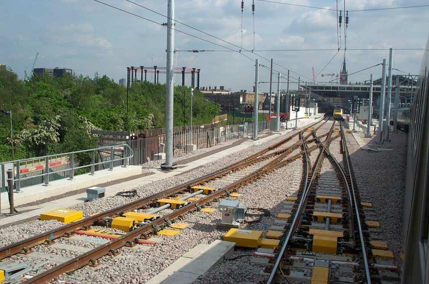
12 Turnouts Specialized geometric objects

13 Turnouts Single, double and slips Tangential and non-tangential turnouts Multiple bending / flexing methods to satisfy various industry standards! Swiss Germany / Austrian UK 13
14 Turnout Library Typical Turnout Library Editor Creation of typical turnouts (standards) The software delivers various country standards German (heavy & light rail) UK (113A s & RT60 s) Indian Railways Dutch Railways / ProRail Spanish Or we will help you to create them AREMA Alternative (US + Canada) Familiar terminology Matches AREMA Track Manuals Delivered with the product 14

15 Advantages of utilizing turnouts Manage the underlying horizontal alignments Once created the software will re-establish the associated turnouts After editing the software updates the associated turnouts and horizontal alignments Maintain the rules for bending turnout geometry 15
")

16 Creating Turnouts Consolidate and minimized functionality (New in V8i) Interface changes based upon library Create from the interface or interactively 16

17 Create Turnout Connections Start with a single turnout and create a connection to a new turnout (New in V8i) A simplification to minimize using the Turnout Connection Editor for simple crossovers Ending turnout will match the beginning turnout. Connection is linear or circular 17

18 Turnout Connection Editor Used for more advanced geometric constructions Crossovers Sidings Editing an existing construction Maintains rules and relationships! 18


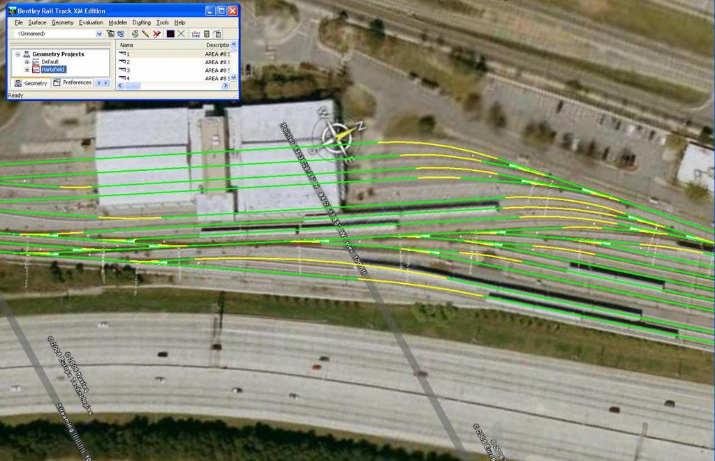
19 Resulting in models like these yards! 19

20 Detailed Design Checking Includes CEN Standards Austrian Rail Danish Rail Dutch Rail German Rail Transrapid Execute as you design Interactive + passive Execute as a post-design process Ideal for checking a consultant s design Written to match the railway s requirements 20


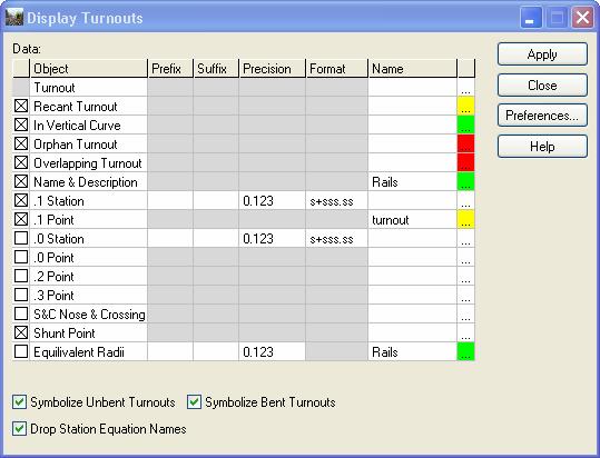
21 Display and also design check 21


22 Working with Leading Suppliers Reading data from Plasser & Theurer s EM-SAT geometry measurement system Advanced long chord measuring resolved to real world coordinates! 22

23 Usability Configurable list views Right click in list view title and check on / off columns Resizing dialogs Cant Alignment Editor Check Integrity Review / Edit Regression Points Others


24 Updated GUI Presentation Implement tree view and grids for various geometry view commands View Stationing View Station &Offset View Curve Set View Vertical in Plan View Switch Height Plan Others Consistency
25 New in V8i (General) Roundabouts was added to the InRoads Group install. Activate the roundabout functionality by clicking a command such as the Civil Library Browser under MicroStation > Tasks > Civil > Roundabouts. Civil AccuDraw is new functionality similar to MicroStation AccuDraw with added civil engineering functionality. Access Civil AccuDraw through the MicroStation Tools menu. Civil Global Positioning System adds civil engineering functionality to the MicroStation > Tools > Geographic > Global Positioning System (GPS) command. Slide 25
26 New in V8i (General) Horizontal Element > Edit Horizontal Element. The Maintain Element Connectivity with Minimum Movement allows the user to change the geometry a line or a circular arc and have the adjacent elements also update. The option utilizes the component technique of fix, float and free to re-compute the geometry. Regression > Edit/Review Regression Points. The Select button is now called Select Only. This button will only select points for regression. The user can still do <Ctrl> + Select to include points in the analysis. The user can still <Shift> + Select to include points in a fence in the analysis. Also, the Regress button is now called Select & Regress. This button will allow the user to select the regression points and automatically perform the regression. The software will stay in this heads-up mode to select and regress multiple elements, until the user rejects. These changes apply to both the Edit / Review Horizontal Regression and Edit / Review Vertical Regression commands. Slide 26
27 New in V8i (General) Regression > Edit/Review Regression Points. The columns are now configurable. Regression > View Regression Points and Evaluation > Profile > Annotate Profile > Horizontal and Vertical Slew leafs. The ability to display the slew values in millimeters was added. Regression points are now removed from the buffer when the corresponding cogo point is deleted. Slide 27
28 New in V8i Translators > Import EM-SAT was added to import data from a Plasser & Theurer survey machine. View Geometry > Stationing. The ability to display cant annotation at a user defined interval was added. Superelevation > Cant Editor. The columns are now configurable. Slide 28
29 New in V8i Geometric element freedoms are now maintained with the data for the life of the data. The following commands are affected: Geometry > Horizontal Regression > Multiple Horizontal Element Regression Analysis Geometry > Vertical Regression > Multiple Vertical Element Regression Analysis Geometry > Turnouts > Turnout Connection Editor Geometry > Turnouts > Create Connection Slide 29
30 New in V8i Horizontal Regression > Multiple Horizontal Element Regression Analysis. Editable Applied Cant fields were added for the Beginning and Ending Elements and an Applied Cant column was added in the Connecting Element list. Horizontal Regression > Multiple Horizontal Element Regression Analysis. If the Beginning Element is the first element in an alignment then the user will be able to edit a linears tangential direction or a circular arcs radius. In a similar manner, if the Ending Element is the last element in an alignment then the user will be able to edit a linears tangential direction or a circular arcs radius. Horizontal Regression > Edit/Review Horizontal Regression Points. Quick Regression was added. Slide 30
31 New in V81 Transition spirals. The cubic parabola spiral implementation has been enhanced for Czech Railways. The primary difference is the Czech cubic parabola is defined by the length along the spirals tangent rather than the length along the centerline. Transition spirals. The cubic parabola spiral implementation has been enhanced for New South Wales, Australia. Transition spirals. The software has been enhanced to also include the America Railway Engineering and Maintenance Associations cubic spiral. The AREMA transition is based upon degree of curvature defined as chord definition. Turnouts. Combined turnouts and the Switch & Crossing (S&C) style of turnouts into a single set of functionality. Within the Create Turnouts and Create Connection commands, the classical style of turnouts now has all of the applicable options that S&C has. Slide 31
32 New in V8i Turnouts. The software now attempts to re-establish orphaned turnouts. Turnouts > Display Turnouts. The ability to display the station at the beginning of a turnout was added. Turnouts > Display Turnouts and Display Turnouts in Profile have been converted to grid views. Turnouts > Create Connection was added. Create Vertical through Turnouts. The computations were simplified to always copy & transform elements to the noncontrolling vertical. Drafting > Network Rail Extensions was added to display turnouts using Network Rail methodology. Light Rail Manufacturing > Annotate Rail Offsets has been enhanced. Utilities > Design Checks > Dutch Rail tab was added. Slide 32
33 Bentley Rail Overhead Line A new product for the creation of overhead line equipment for electrified railways
34 Design Process Reference lines Wire runs Connections Wire height and stagger Structures Other equipment 34

 35 WWW.")
35 Reference Lines Place manually at known locations, relative to fixed locations, or automatically Works around exclusion zones (i.e. underground utilities, etc.) 35

36 Wire Runs Wire runs associated with network track paths Start Anchor Mast Start out of running Mast Start in running Mast Track served by wire Design Wire Run Other Wire Runs Fixed Mast End in running Mast End out of running Mast End Anchor Mast 36

37 Height & Stagger Modify & edit wire staggers Automatically calculates Wind blow off Axial forces Etc. Display design violations! Customizable to specific railway standards! 37


38 Structures Structures types include: Mast single Portal Assembly Create individually or in multiples Utilize templates 38

39 Templates Used for Structures In-span equipment Wire tension equipment User defined Templates Made of assemblies Made of components Graphic & non-graphic data Create once, use over and over! 39


40 Wire Run End Conditions Mid-Wire Tension End Wire Fixity/ Tension 40


41 Other Equipment Transformers Post restraints In span equipment Span bonding 41

42 Reporting Reports XML / XSL Checking Bills of materials Equipment pick lists 42

43 Overhead Line Modeling 43


44 44 Questions?
Bentley Rail Track Update
 Bentley Rail Track Update Robert Nice Bentley Systems UK Recent Past and Near Future Today, I will discuss recent enhancements to Bentley Rail Track. Some of these enhancements you may be very familiar
OpenRail SELECTseries 4 - Managing Geometry and Corridor Modeling
 2015 Bentley Systems, Incorporated OpenRail SELECTseries 4 - Managing Geometry and Corridor Modeling Robert Nice Senior Application Engineer Agenda: Why work in SELECTseries 4? Moving to SELECTseries 4
2014 Bentley Systems, Incorporated. Bentley Rail Track SELECTseries2 Maintenance Release
 2014 Bentley Systems, Incorporated Bentley Rail Track SELECTseries2 Maintenance Release Topics Look back What's in the latest release What's next 2 WWW.BENTLEY.COM 2014 Bentley Systems, Incorporated Previous
X11-Using the New Civil Geometry Tools
 X11-Using the New Civil Geometry Tools Joe Waxmonsky, PE Bentley Civil 2010 Bentley Systems, Incorpo ora 2010 Bentley Systems, Incorpora 2010 Nordic Civil Geometry 2 WWW.BENTLEY.COM Roads and Bridges 2010
Civil Product Update. Derricke Gray, Product Manager Bentley Civil Americas
 Civil Product Update Derricke Gray, Product Manager Bentley Civil Americas 1 WWW.BENTLEY.COM 2016 Bentley Systems, Incorporated 2016 Bentley Systems, Incorporated Agenda Civil Update o Where we are at
Full Contents. InRoads Essentials
 Section 1: Overview Essentials 1.1 Introduction... 3 Learning InRoads... 3 Basic Rules... 3 How to Use This Guide... 4 Section Breakdown... 5 Section 1: Overview Essentials... 5 Section 2: Production Essentials...
AutoCAD Civil 3D 2009 ESSENTIALS
 AutoCAD Civil 3D 2009 ESSENTIALS SDC PUBLICATIONS Schroff Development Corporation www.schroff.com Better Textbooks. Lower Prices. Alignments and Profiles Section 2: Profiles In this section you learn how
Full Contents. Essentials, Workbook
 Section 1: Overview Essentials 1.1 Introduction... 3 Learning InRoads... 3 Basic Rules... 3 How to Use This Guide... 4 Section Breakdown... 5 Section 1: Overview Essentials... 5 Section 2: Production Essentials...
OpenRoads Best Practice - Civil Cells
 OpenRoads Best Practice - Civil Cells Presented by: Ian Rosam, Director Civil Product Management, Bentley Systems, Inc. 1 WWW.BENTLEY.COM 2017 Bentley Systems, Incorporated 2017 Bentley Systems, Incorporated
Lesson 4 Holes and Rounds
 Lesson 4 Holes and Rounds 111 Figure 4.1 Breaker OBJECTIVES Sketch arcs in sections Create a straight hole through a part Complete a Sketched hole Understand the Hole Tool Use Info to extract information
What's the Latest with InRoads Storm & Sanitary SS1?
 What's the Latest with InRoads Storm & Sanitary SS1? Joe Waxmonsky, Bentley Civil Why implement S&S? To avoid this: 2 WWW.BENTLEY.COM Single-source it 3 WWW.BENTLEY.COM StormCAD reads S&S files! StormCAD
Radius Return Select this option to annotate the elevations along the radius return of the intersection.
 ODOT_IntersectionDetail.mvba Application Name: Current version: Required MicroStation Version: Required GEOPAK Version: Video Documentation ODOT_IntersectionDetail.mvba V11.07.15 MicroStation XM or V8i
Civil AccuDraw. Tools > Civil AccuDraw >Activate Toolbar Bentley Systems, Incorporated
 Tools > >Activate Toolbar 2D 3D 2009 Bentley Systems, Incorporated 1 WWW.BENTLEY.COM Toggle 2 WWW.BENTLEY.COM 3 WWW.BENTLEY.COM Z DZ 4 WWW.BENTLEY.COM Distance-Direction Single Origin 5 WWW.BENTLEY.COM
Existing and Design Profiles
 NOTES Module 09 Existing and Design Profiles In this module, you learn how to work with profiles in AutoCAD Civil 3D. You create and modify profiles and profile views, edit profile geometry, and use styles
Engineering Technology
 Engineering Technology Introduction to Parametric Modelling Engineering Technology 1 See Saw Exercise Part 1 Base Commands used New Part This lesson includes Sketching, Extruded Boss/Base, Hole Wizard,
Sicat Master. Engineering of overhead contact line systems. siemens.com/rail-electrification
 Sicat Master Engineering of overhead contact line systems siemens.com/rail-electrification When engineering overhead contact lines for mass transit and main line railways, we combine the calculations of
Bentleyuser.dk Årsmøde 2010 Nordic Civil 2010
 Bentleyuser.dk Årsmøde 2010 Nordic Civil 2010 8.-10. November 2010, Munkebjerg Hotel, Vejle Workshop - X9 Resurfacing and Overlay Tools InRoads V8i Presenter: Joe Waxmonsky, P.E., Bentley Systems USA Bentley
Revit Structure 2014 Basics
 Revit Structure 2014 Basics Framing and Documentation Elise Moss Authorized Author SDC P U B L I C AT I O N S Better Textbooks. Lower Prices. www.sdcpublications.com Powered by TCPDF (www.tcpdf.org) Visit
Creo Parametric 2.0: Introduction to Solid Modeling. Creo Parametric 2.0: Introduction to Solid Modeling
 Creo Parametric 2.0: Introduction to Solid Modeling 1 2 Part 1 Class Files... xiii Chapter 1 Introduction to Creo Parametric... 1-1 1.1 Solid Modeling... 1-4 1.2 Creo Parametric Fundamentals... 1-6 Feature-Based...
Revit Structure 2012 Basics:
 SUPPLEMENTAL FILES ON CD Revit Structure 2012 Basics: Framing and Documentation Elise Moss autodesk authorized publisher SDC PUBLICATIONS www.sdcpublications.com Schroff Development Corporation Structural
Ohio Department of Transportation, VBA Documentation
 Contents 1.1 Current Versions... 2 1.2 Overview... 3 1.3 Supporting Files and Standards... 4 1.3.1 ODOT_Drainage.cel... 4 1.3.2 ODOT2013.ddb... 5 1.4 ODOT_StormSewerPlan2013.mvba... 6 1.4.1 Mode: Place
Bentley Civil Update and Direction
 www. bentley. com Bentley Civil Update and Direction Mike Wilson Director, Software Development, Bentley Civil The cast of characters this year Bentley Civil Mike Wilson that would be me Director, Software
Module 10. Assemblies and Corridors. Objectives
 NOTES Module 10 Assemblies and Corridors In this module, you learn to work with assemblies and corridors in AutoCAD Civil 3D. Corridor models are used to represent road designs in Civil 3D. An assembly
General Guide to RoadPlus Editor
 20 30 40 50 GPS System 500 General Guide to RoadPlus Editor Version 4.0 English System GPS500 Congratulations on your purchase of a new Leica System GPS500. 2 View of chapters Introduction Design Elements
Table of Contents. What's New in GRAITEC Advance BIM Designers 2018 R2 ADVANCE BIM DESIGNERS CONCRETE SERIES... 4
 What's New 2018 R2 Table of Contents ADVANCE BIM DESIGNERS CONCRETE SERIES... 4 REINFORCED CONCRETE FOOTING DESIGNER... 4 Multi-layer soil calculation... 4 Bottom Constructive Reinforcement... 5 REINFORCED
Exercise 1: The AutoCAD Civil 3D Environment
 Exercise 1: The AutoCAD Civil 3D Environment AutoCAD Civil 3D Interface Object Base Layer Object Component Layers 1-1 Introduction to Commercial Site Grading Plans AutoCAD Civil 3D Interface AutoCAD Civil
SolidWorks Part I - Basic Tools SDC. Includes. Parts, Assemblies and Drawings. Paul Tran CSWE, CSWI
 SolidWorks 2015 Part I - Basic Tools Includes CSWA Preparation Material Parts, Assemblies and Drawings Paul Tran CSWE, CSWI SDC PUBLICATIONS Better Textbooks. Lower Prices. www.sdcpublications.com Powered
Introduction to Sheet Metal Features SolidWorks 2009
 SolidWorks 2009 Table of Contents Introduction to Sheet Metal Features Base Flange Method Magazine File.. 3 Envelopment & Development of Surfaces.. 14 Development of Transition Pieces.. 23 Conversion to
Subdivision Cross Sections and Quantities
 NOTES Module 11 Subdivision Cross Sections and Quantities Quantity calculation and cross section generation are required elements of subdivision design projects. After the design is completed and approved
Prasanth. Lathe Machining
 Lathe Machining Overview Conventions What's New? Getting Started Open the Part to Machine Create a Rough Turning Operation Replay the Toolpath Create a Groove Turning Operation Create Profile Finish Turning
GstarCAD Mechanical 2015 Help
 1 Chapter 1 GstarCAD Mechanical 2015 Introduction Abstract GstarCAD Mechanical 2015 drafting/design software, covers all fields of mechanical design. It supplies the latest standard parts library, symbols
Drawing Standard for Plans Showing Horizontal Alignment
 Discipline: Engineering (Track & Civil) Category: Standard Drawing Standard for Plans Showing Horizontal Alignment ETD-00-01 Applicability New South Wales CRIA (NSW CRN) Primary Source ARTC NSW Standard
AECOsim Building Designer. Quick Start Guide. Chapter 2 Making the Mass Model Intelligent Bentley Systems, Incorporated.
 AECOsim Building Designer Quick Start Guide Chapter 2 Making the Mass Model Intelligent 2012 Bentley Systems, Incorporated www.bentley.com/aecosim Table of Contents Making the Mass Model Intelligent...3
Introduction to Autodesk Inventor for F1 in Schools (Australian Version)
") Introduction to Autodesk Inventor for F1 in Schools (Australian Version) F1 in Schools race car In this course you will be introduced to Autodesk Inventor, which is the centerpiece of Autodesk s Digital
Introduction to Autodesk Inventor for F1 in Schools (Australian Version) F1 in Schools race car In this course you will be introduced to Autodesk Inventor, which is the centerpiece of Autodesk s Digital
Revit Structure 2013 Basics
 Revit Structure 2013 Basics Framing and Documentation Elise Moss Supplemental Files SDC P U B L I C AT I O N S Schroff Development Corporation Better Textbooks. Lower Prices. www.sdcpublications.com Tutorial
SD DEPARTMENT OF TRANSPORTATION OFFICE OF ROAD DESIGN
 SD DEPARTMENT OF TRANSPORTATION OFFICE OF ROAD DESIGN CADD Procedures Manual Section B - Design 1 Table of Contents InRoads Master Workflow... 3 Getting Started... 3 Open InRoads Files... 3 Create and
Using Siemens NX 11 Software. The connecting rod
 Using Siemens NX 11 Software The connecting rod Based on a Catia tutorial written by Loïc Stefanski. At the end of this manual, you should obtain the following part: 1 Introduction. Start NX 11 and open
The Revolve Feature and Assembly Modeling
 The Revolve Feature and Assembly Modeling PTC Clock Page 52 PTC Contents Introduction... 54 The Revolve Feature... 55 Creating a revolved feature...57 Creating face details... 58 Using Text... 61 Assembling
SOLIDWORKS 2015 and Engineering Graphics
 SOLIDWORKS 2015 and Engineering Graphics An Integrated Approach Randy H. Shih SDC PUBLICATIONS Better Textbooks. Lower Prices. www.sdcpublications.com Powered by TCPDF (www.tcpdf.org) Visit the following
New Features in TerraScan. Version 013.xxx
 New Features in TerraScan Terrasolid Workshop ILMF 2013 Denver, CO 14 February 2013 Darrick Wagg GeoCue Corporation 9668 Madison Blvd., Suite 202 Madison, AL 35758 +1 (256) 461-8289 support@geocue.com
Inventor Activity 5: Lofted Vase
 Inventor Activity 5: Lofted Vase In this tutorial, you will use a few new commands to create a free form Lofted object. Sometimes you want to create an object that is not made up of square, flat, or perfectly
On completion of this exercise you will have:
 Prerequisite Knowledge To complete this exercise you will need; to be familiar with the SolidWorks interface and the key commands. basic file management skills the ability to rotate views and select faces
DRAFT Solid Edge ST4 Update Training Draft
 DRAFT Solid Edge ST4 Update Training Draft Presented by: Steve Webb Topics Parts List Table Titles Column Headers Headers Merging Header Rotate Cell Aspect Ratio Cell Formatting Overriding Disabled Cells
COPYRIGHTED MATERIAL. Welcome to the Civil 3D Environment
 Welcome to the Civil 3D Environment Chapter 1 To paraphrase, Civil 3D isn t your father s AutoCAD. If you re just getting into the Civil 3D environment, want to learn how to get around in models, and would
GEOPAK V8i SELECTseries 1, Road 2
 GEOPAK V8i SELECTseries 1, Road 2 Ohio Department of Transportation October, 2012 Ohio Department of Transportation GEOPAK Road Training Guide for MicroStation V8i SELECTseries 1, October, 2012 The information
An Introduction to Dimensioning Dimension Elements-
 An Introduction to Dimensioning A precise drawing plotted to scale often does not convey enough information for builders to construct your design. Usually you add annotation showing object measurements
AutoCAD Civil 3D 2013 South African Country Kit
 AutoCAD Civil 3D 2013 South African Country Kit Contents 1 General... 3 1.1 Introduction from the author and creator... 3 1.2 Overview... 4 2 Drawing Settings... 8 2.1 Edit Drawing Settings... 8 3 Layers...
and Engineering Graphics
 SOLIDWORKS 2018 and Engineering Graphics An Integrated Approach Randy H. Shih SDC PUBLICATIONS Better Textbooks. Lower Prices. www.sdcpublications.com Powered by TCPDF (www.tcpdf.org) Visit the following
User Guide V10 SP1 Addendum
 Alibre Design User Guide V10 SP1 Addendum Copyrights Information in this document is subject to change without notice. The software described in this document is furnished under a license agreement or
< Then click on this icon on the vertical tool bar that pops up on the left side.
 Pipe Cavity Tutorial Introduction The CADMAX Solid Master Tutorial is a great way to learn about the benefits of feature-based parametric solid modeling with CADMAX. We have assembled several typical parts
Lesson 6 2D Sketch Panel Tools
 Lesson 6 2D Sketch Panel Tools Inventor s Sketch Tool Bar contains tools for creating the basic geometry to create features and parts. On the surface, the Geometry tools look fairly standard: line, circle,
Advance Steel 2010 / SP2
 Advance Steel 2010 / SP2 This document describes the improvements in Service Pack 2 for Advance Steel 2010. Advance Steel 2010 SP2 is Windows 7 compliant! BOM/LISTS New sorting option in Drawing index
Introducing SolidWorks
 Introducing SolidWorks SAAST Robotics 2008 SolidWorks Software Visually-based 3-D Mechanical design software Engineers and Designers use it to: Quickly sketch out ideas Experiment with features, dimensions
IDEA Connections. User guide
 IDEA Connections user guide IDEA Connections User guide IDEA Connections user guide Content 1.1 Program requirements... 4 1.1 Installation guidelines... 4 2 User interface... 5 2.1 3D view in the main
AUTOCAD CIVIL 3D 2016
 SMALL SCALE AND MICRO IRRIGATION SUPPORT PROJECT Training Manual on AUTOCAD CIVIL 3D 2016 for irrigation professionals SMIS RPMU, Hawassa January 25-30/2017 (Prepared by Abdo Kedir) CONTENTS 1 CIVIL 3D
SolidWorks 95 User s Guide
 SolidWorks 95 User s Guide Disclaimer: The following User Guide was extracted from SolidWorks 95 Help files and was not originally distributed in this format. All content 1995, SolidWorks Corporation Contents
OpenBridge Modeler: What is it and how can I use it today?
 2015 Bentley Systems, Incorporated OpenBridge Modeler: What is it and how can I use it today? Steve Willoughby, Senior Application Engineer Agenda: Introducing OpenBridge Modeler OpenBridge Modeler Features
ME Week 2 Project 2 Flange Manifold Part
 1 Project 2 - Flange Manifold Part 1.1 Instructions This project focuses on additional sketching methods and sketching commands. Revolve and Work features are also introduced. The part being modeled is
Practice Workbook. Cross Sections: Creating, Annotating, and Volumes
 Practice Workbook This workbook is designed for use in Live instructor-led training and for OnDemand selfstudy. The explanations and demonstrations are provided by the instructor in the classroom, or in
Getting Started. Before You Begin, make sure you customized the following settings:
 Getting Started Getting Started Before getting into the detailed instructions for using Generative Drafting, the following tutorial aims at giving you a feel of what you can do with the product. It provides
Introduction to CATIA V5
 Introduction to CATIA V5 Release 17 (A Hands-On Tutorial Approach) Kirstie Plantenberg University of Detroit Mercy SDC PUBLICATIONS Schroff Development Corporation www.schroff.com Better Textbooks. Lower
Explanation of buttons used for sketching in Unigraphics
 Explanation of buttons used for sketching in Unigraphics Sketcher Tool Bar Finish Sketch is for exiting the Sketcher Task Environment. Sketch Name is the name of the current active sketch. You can also
TUTORIAL 4: Combined Axial and Bending Problem Sketch Path Sweep Initial Project Space Setup Static Structural ANSYS
 TUTORIAL 4: Combined Axial and Bending Problem In this tutorial you will learn how to draw a bar that has bends along its length and therefore will have both axial and bending stresses acting on cross-sections
An Introduction to Autodesk Inventor 2011 and AutoCAD Randy H. Shih SDC PUBLICATIONS. Schroff Development Corporation
 An Introduction to Autodesk Inventor 2011 and AutoCAD 2011 Randy H. Shih SDC PUBLICATIONS www.sdcpublications.com Schroff Development Corporation An Introduction to Autodesk Inventor 2011 and AutoCAD 2011
AEROPLANE. Create a New Folder in your chosen location called Aeroplane. The four parts that make up the project will be saved here.
 AEROPLANE Prerequisite Knowledge Previous knowledge of the following commands is required to complete this lesson. Sketching (Line, Rectangle, Arc, Add Relations, Dimensioning), Extrude, Assemblies and
Resurfacing and Overlay Made Easy with New Overlay Tools in Roadway Designer
 Resurfacing and Overlay Made Easy with New Overlay Tools in Roadway Designer Joe Waxmonsky, Bentley Civil 2 WWW.BENTLEY.COM Why Overlay? Why Overlay? Accommodate wedging / leveling Milling Widening Crown
To apply proposed roadway data (vertical alignments, cross section template data, cut/fill slopes, etc.)
") That CAD Girl J ennifer dib ona Website: www.thatcadgirl.com Email: thatcadgirl@aol.com Phone: (919) 417-8351 Fax: (919) 573-0351 Roadway Design Extracting Existing Ground Cross Sections This document
That CAD Girl J ennifer dib ona Website: www.thatcadgirl.com Email: thatcadgirl@aol.com Phone: (919) 417-8351 Fax: (919) 573-0351 Roadway Design Extracting Existing Ground Cross Sections This document
Practice Workbook. Cross Sections: Creating, Annotating, and Volumes. SELECTseries 4 ( ) or newer
 or newer") Practice Workbook This workbook is designed for use in Live instructor-led training and for OnDemand self study. The explanations and demonstrations are provided by the instructor in the classroom, or
Practice Workbook This workbook is designed for use in Live instructor-led training and for OnDemand self study. The explanations and demonstrations are provided by the instructor in the classroom, or
Shaft Hanger - SolidWorks
 ME-430 INTRODUCTION TO COMPUTER AIDED DESIGN Shaft Hanger - SolidWorks BY: DR. HERLI SURJANHATA ASSIGNMENT Submit TWO isometric views of the Shaft Hanger with your report, 1. Shaded view of the trimetric
Evaluation Chapter by CADArtifex
 The premium provider of learning products and solutions www.cadartifex.com EVALUATION CHAPTER 2 Drawing Sketches with SOLIDWORKS In this chapter: Invoking the Part Modeling Environment Invoking the Sketching
Autodesk Advance Steel. Drawing Style Manager s guide
 Autodesk Advance Steel Drawing Style Manager s guide TABLE OF CONTENTS Chapter 1 Introduction... 5 Details and Detail Views... 6 Drawing Styles... 6 Drawing Style Manager... 8 Accessing the Drawing Style
AutoCAD 2D I. Module 16. Isometric and Dimensioning. IAT Curriculum Unit PREPARED BY. January 2011
 AutoCAD 2D I Module 16 Isometric and Dimensioning PREPARED BY IAT Curriculum Unit January 2011 Institute of Applied Technology, 2011 Module 16 Auto CAD Self-paced Learning Modules AutoCAD 2D Isometric
AUTODESK INVENTOR Trial Projects
 AUTODESK INVENTOR Trial Projects Drawing Creation Create detailed drawings of a collar flange PART 1: CREATING DRAWING VIEWS page: 2 1. 2. 3. Start by clicking the Projects icon in the ribbon. Navigate
Alternatively, the solid section can be made with open line sketch and adding thickness by Thicken Sketch.
 Sketcher All feature creation begins with two-dimensional drawing in the sketcher and then adding the third dimension in some way. The sketcher has many menus to help create various types of sketches.
Applied Steel Detailing Tekla Structures 11.0 Basic Training February 10, 2005
 Tekla Structures 11.0 Basic Training February 10, 2005 Copyright 2005 Tekla Corporation Contents Contents...i 1...3 1.1 AutoConnections...4 1.2 General about the Criteria for Creating Connections...6 1.3
Sheet Metal OverviewChapter1:
 Sheet Metal OverviewChapter1: Chapter 1 This chapter describes the terminology, design methods, and fundamental tools used in the design of sheet metal parts. Building upon these foundational elements
Advance Steel. Drawing Style Manager s guide
 Advance Steel Drawing Style Manager s guide TABLE OF CONTENTS Chapter 1 Introduction...7 Details and Detail Views...8 Drawing Styles...8 Drawing Style Manager...9 Accessing the Drawing Style Manager...9
Advance Steel. Tutorial
 Advance Steel Tutorial Table of contents About this tutorial... 7 How to use this guide...9 Lesson 1: Creating a building grid...10 Step 1: Creating an axis group in the X direction...10 Step 2: Creating
BASIC TERMS OF ROAD GEOMETRY
 BASIC TERMS OF ROAD GEOMETRY Contour line = a line, which connects terrain points of the same elevation Contour line interval (equidistance) = elevation difference between contour lines Line of maximum
SurvCADDR. Section - Profile Module. File Modify Display Draw Inq-Set Pnts Profiles Design Sections Misc PRODUCT DESCRIPTION BENEFITS & ADVANTAGES
 File Modify Display Draw Inq-Set Pnts Profiles Design Sections Misc SurvCADDR Section - Profile Module PRODUCT DESCRIPTION engineeringsoftwareforanexpandinguniverse The Section - Profile Module creates
AutoCAD Inventor - Solid Modeling, Stress and Dynamic Analysis
 PDHonline Course G280 (15 PDH) AutoCAD Inventor - Solid Modeling, Stress and Dynamic Analysis Instructor: John R. Andrew, P.E. 2012 PDH Online PDH Center 5272 Meadow Estates Drive Fairfax, VA 22030-6658
Lesson 16 Helical Sweeps and Annotations
 Lesson 16 Helical Sweeps and Annotations Figure 16.1 Helical Compression Spring Drawing OBJECTIVES Create a helical compression spring with a Helical Sweep Use sweeps to create hooks on extension springs
SolidWize. Online SolidWorks Training. Simple Sweep: Head Scratcher
 SolidWize Online SolidWorks Training Simple Sweep: Head Scratcher Step 1: Creating the Handle: Sketch Using Inches as the unit create a sketch on the Front plane. Start with the sketch shown below: Create
Full Contents. Survey V8.08 Essentials
 Section 1: Overview Essentials 1.1 Introduction... 3 Learning InRoads Survey... 3 Basic Rules... 3 How to Use This Guide... 4 Section Breakdown... 5 Section 1: Overview Essentials... 5 Section 2: Production
1.6.7 Add Arc Length Dimension Modify Dimension Value Check the Sketch Curve Connectivity
 Contents 2D Sketch... 1 1.1 2D Sketch Introduction... 1 1.1.1 2D Sketch... 1 1.1.2 Basic Setting of 2D Sketch... 2 1.1.3 Exit 2D Sketch... 4 1.2 Draw Common Geometry... 5 2.2.1 Points... 5 2.2.2 Lines
5 More Than Straight Lines
 5 We have drawn lines, shapes, even a circle or two, but we need more element types to create designs efficiently. A 2D design is a flat representation of what are generally 3D objects, represented basically
Generative Drafting (ISO)
") CATIA Training Foils Generative Drafting (ISO) Version 5 Release 8 January 2002 EDU-CAT-E-GDRI-FF-V5R8 1 Table of Contents (1/2) 1. Introduction to Generative Drafting Generative Drafting Workbench Presentation
CATIA Training Foils Generative Drafting (ISO) Version 5 Release 8 January 2002 EDU-CAT-E-GDRI-FF-V5R8 1 Table of Contents (1/2) 1. Introduction to Generative Drafting Generative Drafting Workbench Presentation
Toothbrush Holder. A drawing of the sheet metal part will also be created.
 Prerequisite Knowledge Previous knowledge of the following commands is required to complete this lesson; Sketch (Line, Centerline, Circle, Add Relations, Smart Dimension,), Extrude Boss/Base, and Edit
3D Modeling Demonstration
 2014 Bentley Systems, Incorporated 3D Modeling Demonstration Derricke Gray, Product Manager Bentley Civil Americas ESS Statewide Rollouts: 3D Modeling Engineering Content Management (ProjectWise) 2 WWW.BENTLEY.COM
Release Notes - Fixes in Tekla Structures 2016i PR1
 Release Notes - Fixes in Tekla Structures 2016i PR1, you can now set the to either or. is modified., the ID of the connection plate is not changed anymore when the connection now uses normal rebar groups
AutoDesk Inventor: Creating Working Drawings
 AutoDesk Inventor: Creating Working Drawings Inventor allows you to quickly and easily make quality working drawings from your 3D models. This tutorial will walk you through the steps in creating a working
Generative Drafting Overview What's New Getting Started User Tasks
 Generative Drafting Overview Conventions What's New Getting Started Defining the Drawing Sheet Part Drawing Opening a Part Creating a Front View Creating a Projection View Creating a Section View Creating
Table of Contents. Dedication Preface. Chapter 1: Introduction to CATIA V5-6R2015. Chapter 2: Drawing Sketches in the Sketcher Workbench-I.
 Table of Contents Dedication Preface iii xvii Chapter 1: Introduction to CATIA V5-6R2015 Introduction to CATIA V5-6R2015 1-2 CATIA V5 Workbenches 1-2 System Requirements 1-4 Getting Started with CATIA
Architecture 2012 Fundamentals
 Autodesk Revit Architecture 2012 Fundamentals Supplemental Files SDC PUBLICATIONS Schroff Development Corporation Better Textbooks. Lower Prices. www.sdcpublications.com Tutorial files on enclosed CD Visit
Virtual components in assemblies
 Virtual components in assemblies Publication Number spse01690 Virtual components in assemblies Publication Number spse01690 Proprietary and restricted rights notice This software and related documentation
Module 2: Radial-Line Sheet-Metal 3D Modeling and 2D Pattern Development: Right Cone (Regular, Frustum, and Truncated)
") Inventor (5) Module 2: 2-1 Module 2: Radial-Line Sheet-Metal 3D Modeling and 2D Pattern Development: Right Cone (Regular, Frustum, and Truncated) In this tutorial, we will learn how to build a 3D model
Inventor (5) Module 2: 2-1 Module 2: Radial-Line Sheet-Metal 3D Modeling and 2D Pattern Development: Right Cone (Regular, Frustum, and Truncated) In this tutorial, we will learn how to build a 3D model
Creo Parametric 4.0 Advanced Design
 Table of Introduction...1 Objective of This Book...1 Textbook Outline...2 Textbook Conventions...3 Exercise Files...3 System Configuration...4 Datum Features...5 Introduction...5 Sketches and Datum Curves...6
Table of contents. User interface 1: Customizable tool palette... 6 User interface 2: General GUI improvements... 7
 Table of contents WELCOME TO ADVANCE CONCRETE 2014... 5 USER INTERFACE ENHANCEMENTS... 6 User interface 1: Customizable tool palette... 6 User interface 2: General GUI improvements... 7 MODELING... 10