TCSS 372 Laboratory Project 2 RS 232 Serial I/O Interface
|
|
|
- Reynold Cross
- 5 years ago
- Views:
Transcription
1 11/20/06 TCSS 372 Laboratory Project 2 RS 232 Serial I/O Interface BACKGROUND In the early 1960s, a standards committee, known as the Electronic Industries Association (EIA), developed a common serial bus interface standard for asynchronous data communications equipment, named RS232. It is still used today for connecting peripheral equipment, like printers, to computers, as well as connecting computers together. It is now being replaced by a faster asynchronous serial bus, USB or Universal Serial Bus. Originally, data communications was thought to mean digital data exchange between a centrally located mainframe computer and a remote computer terminal, or possibly between two terminals without a computer involved. These devices were linked by telephone voice lines, and consequently required a modem at each end for signal translation. While simple in concept, the many opportunities for data error that occur when transmitting data through an analog channel require a relatively complex design. It was thought that a standard was needed first to ensure reliable communication, and second to enable the interconnection of equipment produced by different manufacturers, thereby fostering the benefits of mass production and competition. It specified signal voltages, signal timing, signal function, a protocol for information exchange, and mechanical connectors. You will see both 25 pin and 9 pin connectors used for RS232 today. If the full EIA232 standard is implemented as defined, the equipment at the far end (left end below) of the connection is named the DTE device (Data Terminal Equipment, usually a computer or terminal), and has a male connector. Equipment at the near end (right end below) of the connection (the telephone line interface) is named the DCE device (Data Circuit-terminating Equipment or Data Communications Equipment, usually a modem), has a female connector, and utilizes the same available pins for signals and ground. The cable linking DTE and DCE devices is a parallel straight-through cable with no cross-overs or self-connects in the connector hoods. If all devices exactly followed this standard, all cables would be identical, and there would be no chance that an incorrectly wired cable could be used. This drawing shows the orientation and connector types for DTE and DCE devices:

2 The signals on an RS232 9 pin connector are: If one wants to connect two computers together, a "null modem" connection can be used in place of the pair of modems. Since both computers are DTE's, the straight through connection from a DTE to a DCE will not work. A null modem crosses the send and receive lines and connects the other wires, the flow control or "handshaking signals", correctly for a DTE to communicate with another DTE. The configuration for a null modem is: "Full Handshaking Null Modem" Sometimes null modems are connected with "loop back" connections to "fake" the handshaking as follows: "Loop back Handshaking Null Modem" Sometimes designers actually don't bother with the handshaking signals at all. They don't program the equipment to either look at or to generate the signals:
3 "No Handshaking Null Modem" This lack of standard for a connection often gives one fits when configuring a system! Maybe you have been there? For our project we will ignore handshaking. That will make it simpler for us, but still not at all trivial. RS232 transmits a sequence of bytes, each of which is transmitted as a sequence of pulses. These pulses are sent at a selected Baud (or bit) rate: Baud rate: Max speed of transmission of bits: Typically 110, 300, 1200, 2400, 4800, 9600, bits/sec The protocol for the sequence of pulses representing the bytes of ASCII Characters is: Start bit: A first bit always of the same polarity for equipment to sync on Data Bits: The useful data follows the start bit: Typically 5, 6, 7, or 8 bits Parity Bit: A bit used for error checking: Even Parity, Odd Parity, Mark Parity, Space Parity, No Parity Stop Bits: The trailing bits after the data and parity to ensure time to "catch" data between bytes: Typically 1, 1.5, or 2 bits Understand that both communicating devices must be using the same protocol parameters for the communication to be successful. Here is an example Java program that sends characters or strings of characters over the cable. You may want to use a version of it to generate your characters on the host computer: import java.io.*; import javax.comm.*; public class SimpleWrite { public static void main(string[] args) throws Exception { OutputStream outputstream; outputstream = get_the_serial_port(); byte[] data = {'a'}; for (int i = 0; i < 1000; i++) { outputstream.write(data); // string sent System.out.println ("i = " + i); Thread.sleep(1000); // milliseconds suspended } } public static OutputStream get_the_serial_port() throws Exception
; return serialport.getoutputstream(); This program uses the javax.comm package.")
4 } { } CommPortIdentifier portid; portid = CommPortIdentifier.getPortIdentifier("COM1"); // COM Port # SerialPort serialport; serialport = (SerialPort) portid.open("simplewriteapp", 2000); serialport.setserialportparams(9600, // baud rate SerialPort.DATABITS_8, SerialPort.STOPBITS_1, SerialPort.PARITY_NONE); return serialport.getoutputstream(); This program uses the javax.comm package. It is not included in the java JDK(jre). It can be obtained at: OBJECTIVE We want to design and build an interface that will capture characters sent by the host computer via the RS 232 serial protocol, and display the data bits on LED s. ASSIGNMENT (Work in pairs.) 1) Do the following procedure to understand the RS-232 protocol: a) Hook channel 1 of the analog oscilloscope to the output of a serial port (Ground is pin 5). The transmitted signal is on pin 3. Here is a picture of our oscilloscope connected to the serial cable from our computer.
5 Hook channel 2 to the pulse generator output and set the pulse rate to approximately 9600 Hz. b) Transmit a character using Java Comm Library (javax.comm is installed on the laboratory computer JDK's). Describe what you see. Draw a picture of your wave form identifying the frequency, voltage between the transmitted character, the value of a "1" and a "0" level, the start bit, the data bits and their order and orientation, the partiy bit, and the stop bits. Explain how you know those identifications are correct. How did you use the pulse generator display to confirm your identification of the bit rate? c) Transmit a zero (the number 0, not the character '0'), and record the result. d) Choose other characters to transmit, and record the results. e) Choose alternate values for EACH parameter: Baud rates, data bits, parity, and stop bits. Record the results and observations. 2) Design a logic circuit that will capture a character sent. Each time a new character is sent, it should replace the last value. Lets assume the protocol is 1 start bit, 8 data bits, no parity, and two stop bits. Use a 1489 Line Receivers to buffer the signal from the RS-232 line. The voltage levels on the RS-232 cable are approximately 15 volts. The 1489 Line Receiver will handle these and give you a 1 level consistent with 5 volt logic. I would use a 74HC163 4-bit synchronous binary counter for the state machine to control your circuit. The 74HC163 has a synchronous reset. That means that the reset occurs on the next clock pulse after the reset signal appears on the reset pin. I would use a 74HC164 8-bit synchronous shift register to capture the character bits. The outputs can be connected to leds in series with 1k current limiting resistors (we don t want to burn out the leds). 3) After you are comfortable that your design should work, build and test your circuit. REPORT Each individual should submit a formal report. Your report should include documentation of your lab results. Notes: 1) In general, don t leave control inputs open. They should be connected to a logical 1 or a logical 0. 2) The 74HC163 Synchronous Binary Counter has a synchronous reset, i.e., it resets when the reset input is a logical 0 on the rising edge of the clock.
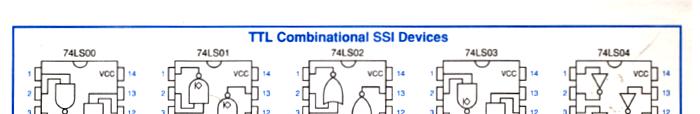
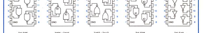
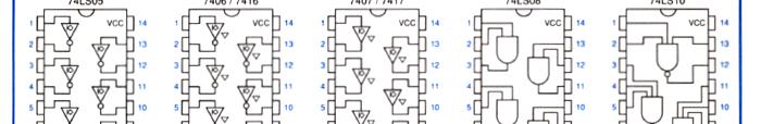
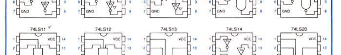
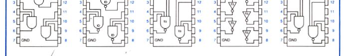
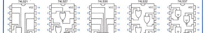
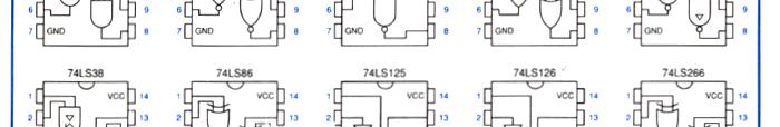
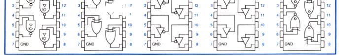
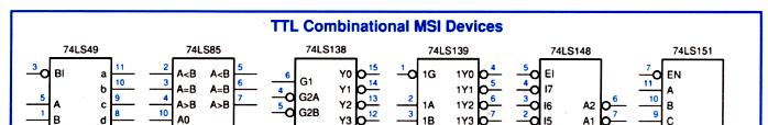
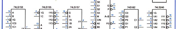
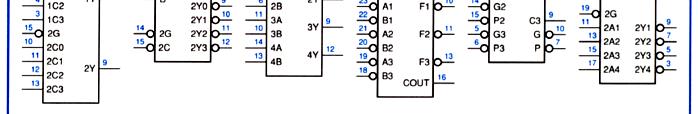
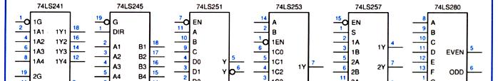
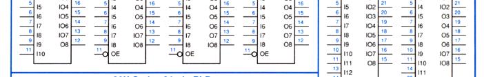
6 3) The 1489 is an inverting buffer. It accepts an input significantly higher than a logical 1, like the15 volts that the RS-232 line provides. The control inputs on it SHOULD be left open! 4) Our chip inventory includes: 74xx00 2 Input Nand Gates (4) 74xx02 2 Input Nor Gates (4) 74xx04 Invertors (6) 74xx08 2 Input And Gates (4) 74xx32 2 Input Or Gates (4) 74xx74 D Flip Flops (2) 74xx109 J/K Flip Flops (2) 74xx112 J/K Inverted Clock Flip Flops (2) 74xx125 Tri-state Buffers (4) 74xx163 4 Bit Sync Binary Counter with Sync Reset (1) 74xx164 8 Bit Synchronous Shift Register (1) MC1489 Inverting Line Receivers (4)
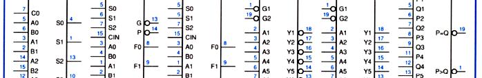
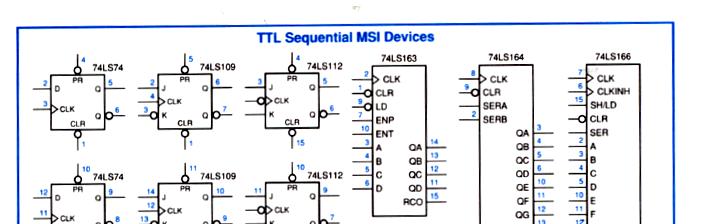
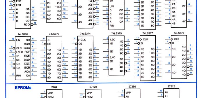
7 74HC163 4 Bit Synchronous Binary Counter: 74HC164 8 Bit Synchronous Shift Register:
8 MC1489N Quad Line Receiver: Note: The control inputs on it SHOULD be left open!
9
10

11
12
EECE494: Computer Bus and SoC Interfacing. Serial Communication: RS-232. Dr. Charles Kim Electrical and Computer Engineering Howard University
 EECE494: Computer Bus and SoC Interfacing Serial Communication: RS-232 Dr. Charles Kim Electrical and Computer Engineering Howard University Spring 2014 1 Many types of wires/pins in the communication
APPLICATION BULLETIN. SERIAL BACKGROUNDER (Serial 101) AB23-1. ICS ICS ELECTRONICS division of Systems West Inc. INTRODUCTION CHAPTER 2 - DATA FORMAT
 AB23-1. ICS ICS ELECTRONICS division of Systems West Inc. INTRODUCTION CHAPTER 2 - DATA FORMAT") ICS ICS ELECTRONICS division of Systems West Inc. AB- APPLICATION BULLETIN SERIAL BACKGROUNDER (Serial 0) INTRODUCTION Serial data communication is the most common means of transmitting data from one point
ICS ICS ELECTRONICS division of Systems West Inc. AB- APPLICATION BULLETIN SERIAL BACKGROUNDER (Serial 0) INTRODUCTION Serial data communication is the most common means of transmitting data from one point
ROM/UDF CPU I/O I/O I/O RAM
 DATA BUSSES INTRODUCTION The avionics systems on aircraft frequently contain general purpose computer components which perform certain processing functions, then relay this information to other systems.
Electronics / Water analogy. Resistor. Inductance. Capacitor. Water Electronics Energy - Energy Pressure - Voltage Flow - Current Volume - Charge
 Electronics / Water analogy Water Electronics Energy - Energy Pressure - Voltage Flow - Current Volume - Charge Resistor U = R * I 1 Capacitor U 1 i dt C U L di dt Inductance Turbine Flywheel Diode Transistor
EE 314 Spring 2003 Microprocessor Systems
 EE 314 Spring 2003 Microprocessor Systems Laboratory Project #9 Closed Loop Control Overview and Introduction This project will bring together several pieces of software and draw on knowledge gained in
Lab 5. Binary Counter
 Lab. Binary Counter Overview of this Session In this laboratory, you will learn: Continue to use the scope to characterize frequencies How to count in binary How to use an MC counter Introduction The TA
Lab 6. Binary Counter
 Lab 6. Binary Counter Overview of this Session In this laboratory, you will learn: Continue to use the scope to characterize frequencies How to count in binary How to use an MC14161 or CD40161BE counter
Serial Input/Output. Lecturer: Sri Parameswaran Notes by: Annie Guo
 Serial Input/Output Lecturer: Sri Parameswaran Notes by: Annie Guo 1 Serial communication Concepts Standards USART in AVR Lecture overview 2 Why Serial I/O? Problems with Parallel I/O: Needs a wire for
Unit D. Serial Interfaces. Serial vs. Parallel. Serial Interfaces. Serial Communications
 D.1 Serial Interfaces D.2 Unit D Embedded systems often use a serial interface to communicate with other devices. Serial implies that it sends or receives one bit at a time. Serial Communications Serial
Chapter 15: Serial Controlled (HF) Radio Support
 Radio Support") 15-1 Chapter 15: Serial Controlled (HF) Radio Support This section describes the controller's interface for serial controlled radios. Most such radios are for the HF bands, but some such as the FT-736
15-1 Chapter 15: Serial Controlled (HF) Radio Support This section describes the controller's interface for serial controlled radios. Most such radios are for the HF bands, but some such as the FT-736
EIG DNP V3.0 Protocol Assignments
 E Electro Industries/G augetech "The Leader in Web Accessed Power Monitoring" EIG DNP V3.0 Protocol Assignments For Futura+ and DM Series Power Monitors Version 1.14 July 15, 2003 Doc # E100-7-03 V1.14
COMP467. Local Asynchronous Communication. Goals. Data is usually sent over a single channel one bit at a time.
 COMP467 Local Asynchronous Communication Goals Understand the RS-232 transmission format Be able to compute the parity of a byte Understand the difference between baud and bits per second Be able to calculate
EXPERIMENT NO:-1. OBJECTIVE: To study Basics of serial communication ports and protocols.
 EXPERIMENT NO:-1 OBJECTIVE: To study Basics of serial communication ports and protocols. EQUIPMENTS: DCT-03 Kit 9 Pin D connector Cables 2 Nos. Computers 2 nos. Connecting Chords. Power Supply. THEORY:
WTPCT-M. eeder. Pulse Counter/Timer Module. Technologies FEATURES SPECIFICATIONS DESCRIPTION. Weeder Technologies
 eeder Technologies 90-A Beal Pkwy NW, Fort Walton Beach, FL 32548 www.weedtech.com 850-863-5723 Pulse Counter/Timer Module FEATURES Reads frequency from 0.50000 to 1,400,000 Hz using 5 digit resolution
King Fahd University of Petroleum & Minerals Computer Engineering Dept
 King Fahd University of Petroleum & Minerals Computer Engineering Dept COE 342 Data and Computer Communications Term 021 Dr. Ashraf S. Hasan Mahmoud Rm 22-144 Ext. 1724 Email: ashraf@ccse.kfupm.edu.sa
WTDIN-M. eeder. Digital Input Module. Technologies FEATURES SPECIFICATIONS DESCRIPTION. Weeder Technologies
 eeder Technologies 90-A Beal Pkwy NW, Fort Walton Beach, FL 32548 www.weedtech.com 850-863-5723 Digital Input Module FEATURES 8 wide-range digital input channels with high voltage transient protection.
WTDOT-M. eeder. Digital Output Module. Technologies FEATURES SPECIFICATIONS DESCRIPTION. Weeder Technologies
 eeder Technologies 90-A Beal Pkwy NW, Fort Walton Beach, FL 32548 www.weedtech.com 850-863-5723 Digital Output Module FEATURES 8 high-current open-collector output channels with automatic overload shutdown.
Number system: the system used to count discrete units is called number. Decimal system: the number system that contains 10 distinguished
 Number system: the system used to count discrete units is called number system Decimal system: the number system that contains 10 distinguished symbols that is 0-9 or digits is called decimal system. As
CHAPTER 10: DIGITAL INSTRUMENTATION PRINCIPLES
 I. Why digital? CHAPTER 10: DIGITAL INSTRUMENTATION PRINCIPLES Almost all the transducers we have considered so far have had an analog output, that is, the output is a different form from the input but
USING RS-232 to RS-485 CONVERTERS (With RS-232, RS-422 and RS-485 devices)
") ICS DataCom Application Note USING RS- to RS- CONVERTERS (With RS-, RS- and RS- devices) INTRODUCTION Table RS-/RS- Logic Levels This application note provides information about using ICSDataCom's RS-
ICS DataCom Application Note USING RS- to RS- CONVERTERS (With RS-, RS- and RS- devices) INTRODUCTION Table RS-/RS- Logic Levels This application note provides information about using ICSDataCom's RS-
1. The decimal number 62 is represented in hexadecimal (base 16) and binary (base 2) respectively as
 and binary (base 2) respectively as") BioE 1310 - Review 5 - Digital 1/16/2017 Instructions: On the Answer Sheet, enter your 2-digit ID number (with a leading 0 if needed) in the boxes of the ID section. Fill in the corresponding numbered
BioE 1310 - Review 5 - Digital 1/16/2017 Instructions: On the Answer Sheet, enter your 2-digit ID number (with a leading 0 if needed) in the boxes of the ID section. Fill in the corresponding numbered
Concept of Serial Communication
 Concept of Serial Communication Agenda Serial v.s. Parallel Simplex, Half Duplex, Full Duplex Communication RS-485 Advantage over RS-232 Serial v.s. Parallel Application: How to Measure the temperature
EVDP610 IXDP610 Digital PWM Controller IC Evaluation Board
 IXDP610 Digital PWM Controller IC Evaluation Board General Description The IXDP610 Digital Pulse Width Modulator (DPWM) is a programmable CMOS LSI device, which accepts digital pulse width data from a
NETWORK. TE = Terminal Equipment (DTE - Data Terminal Equipment) NT = Network - Terminating Equipment (DCE - Data Circuit - Terminating Equipment)
 NT = Network - Terminating Equipment (DCE - Data Circuit - Terminating Equipment)") NETWORK INTERFACING TE NT NETWORK NT TE Interface Interface TE = Terminal Equipment (DTE - Data Terminal Equipment) NT = Network - Terminating Equipment (DCE - Data Circuit - Terminating Equipment) Interface
NETWORK INTERFACING TE NT NETWORK NT TE Interface Interface TE = Terminal Equipment (DTE - Data Terminal Equipment) NT = Network - Terminating Equipment (DCE - Data Circuit - Terminating Equipment) Interface
PART 4 DIGITAL METHODS. Chapter 13 Digital Fundamentals. Parallel Data Transfer. Fig Parallel data handshaking
 PART 4 DIGITAL METHODS Chapter 13 Digital Fundamentals The remainder of this book will deal with digital methods in modern communications. We will build on the introduction to digital data in Chapter 3,
LCM100 USER GUIDE. Line Carrier Modem INDUSTRIAL DATA COMMUNICATIONS
 USER GUIDE INDUSTRIAL DATA COMMUNICATIONS LCM100 Line Carrier Modem It is essential that all instructions contained in the User Guide are followed precisely to ensure proper operation of equipment. Product
Chapter 12: Digital Modulation and Modems
 Chapter 12: Digital Modulation and Modems MULTIPLE CHOICE 1. FSK stands for: a. Full-Shift Keying c. Full-Signal Keying b. Frequency-Shift Keying d. none of the above 2. PSK stands for: a. Pulse-Signal
Chapter 9: Serial Communication Interface SCI. The HCS12 Microcontroller. Han-Way Huang. September 2009
 Chapter 9: Serial Communication Interface SCI The HCS12 Microcontroller Han-Way Huang Minnesota State t University, it Mankato September 2009 H. Huang Transparency No.9-1 Why Serial Communication? Parallel
Fanuc Serial (RS232) Communications Information
 Communications Information") Memex Automation Inc. 777 Walkers Line, Burlington, Ontario Canada L7N 2G1 Fanuc Serial (RS232) Communications Information Contents Signal Description Fanuc Serial Cable Information Timing Chart When The
Memex Automation Inc. 777 Walkers Line, Burlington, Ontario Canada L7N 2G1 Fanuc Serial (RS232) Communications Information Contents Signal Description Fanuc Serial Cable Information Timing Chart When The
GP4 PC Servo Control Kit 2003 by AWC
 GP4 PC Servo Control Kit 2003 by AWC AWC 310 Ivy Glen League City, TX 77573 (281) 334-4341 http://www.al-williams.com/awce.htm V1.0 30 Aug 2003 Table of Contents Overview...1 If You Need Help...1 Building...1
ECE 4510/5530 Microcontroller Applications Week 6 Lab 5
 Microcontroller Applications Week 6 Lab 5 Dr. Bradley J. Bazuin Associate Professor Department of Electrical and Computer Engineering College of Engineering and Applied Sciences Lab 5 Element Hardware
ANALOG AND DIGITAL PHYSICAL INTERFACES
 ANALOG AND DIGITAL PHYSICAL INTERFACES Habib Youssef, Ph.D youssef@ccse.kfupm.edu.sa Department of Computer Engineering King Fahd University of Petroleum and Minerals Dhahran, Saudi Arabia COMPUTER NETWORK
Debugging a Boundary-Scan I 2 C Script Test with the BusPro - I and I2C Exerciser Software: A Case Study
 Debugging a Boundary-Scan I 2 C Script Test with the BusPro - I and I2C Exerciser Software: A Case Study Overview When developing and debugging I 2 C based hardware and software, it is extremely helpful
WIEG4PRT-A Four port Wiegand to RS232 Converter.
 WIEG4PRT-A Four port Wiegand to RS232 Converter. Designed for embedding into products manufactured by third-parties, this Wiegand to RS232 converter is designed with 4 ports for taking up to 4 Wiegand
WIE232-A Dual Wiegand to RS232 Converter.
 WIE232-A Dual Wiegand to RS232 Converter. Designed for embedding into products manufactured by third-parties, this Wiegand to RS232 converter is designed with 2 ports for taking up to 2 Wiegand sources
Interface: Serial EIA RS-232D/CCITT V.24, DCE; RTS/CTS delay 0,8 or 64 ms (user-selectable).
.") BLACK BOX PWR RTS TD-1 RD-1 TD-2 DCD RD-2 TEST DIG ANA REM LDM-MR 19.2 REM ANA DIG AGC 2/4 WIRE ABLE / ABLE SWITCHES 2 W 4 W 1 2 3 4 CARRIER LEVEL 0 dbm -3 dbm -6 dbm -9 dbm PIN 21 (RLB) RPF PIN 18 AN.
BLACK BOX PWR RTS TD-1 RD-1 TD-2 DCD RD-2 TEST DIG ANA REM LDM-MR 19.2 REM ANA DIG AGC 2/4 WIRE ABLE / ABLE SWITCHES 2 W 4 W 1 2 3 4 CARRIER LEVEL 0 dbm -3 dbm -6 dbm -9 dbm PIN 21 (RLB) RPF PIN 18 AN.
Sequential Logic Circuits
 LAB EXERCISE - 5 Page 1 of 6 Exercise 5 Sequential Logic Circuits 1 - Introduction Goal of the exercise The goals of this exercise are: - verify the behavior of simple sequential logic circuits; - measure
Microcontrollers. Serial Communication Interface. EECE 218 Microcontrollers 1
 EECE 218 Microcontrollers Serial Communication Interface EECE 218 Microcontrollers 1 Serial Communications Principle: transfer a word one bit at a time Methods:» Simplex: [S] [R]» Duplex: [D1] [D2]» Half
Stensat Transmitter Module
 Stensat Transmitter Module Stensat Group LLC Introduction The Stensat Transmitter Module is an RF subsystem designed for applications where a low-cost low-power radio link is required. The Transmitter
DigiPoints Volume 1. Student Workbook. Module 2 Modem Overview
 Modem Overview Page 2.1 DigiPoints Volume 1 Module 2 Modem Overview Summary One of the potential advantages the cable telecommunications industry has is the ability to carry data signals at speeds significantly
This section of the manual will document the Ad-Maestro s control ports, COMM Ports and their settings respectively.
 This section of the manual will document the Ad-Maestro s control ports, COMM Ports and their settings respectively. Parallel - The Parallel port provides a control interface with video devices utilizing
Lecture #3 RS232 & 485 protocols
 SPRING 2015 Integrated Technical Education Cluster At AlAmeeria E-626-A Data Communication and Industrial Networks (DC-IN) Lecture #3 RS232 & 485 protocols Instructor: Dr. Ahmad El-Banna 1 Agenda What
CALIFORNIA SOFTWARE LABS
 Pulse Shaping on the Palm Pilot With serial, infrared and remote control applications CALIFORNIA SOFTWARE LABS R E A L I Z E Y O U R I D E A S California Software Labs 6800 Koll Center Parkway, Suite 100
This FAQ covers Single Direction use of current loop with transmitting devices.
 PAGE 1 OF 5 This FAQ covers Single Direction use of current loop with transmitting devices. Q: How do I connect the Current Loop Converter to my Current Loop device? A: This Current Loop interface has
PRODUCT INFORMATION B&B ELECTRONICS. Port-Powered RS-232 Fiber Optic Modem with Handshake Support. Model 9PFLST. Description. RS-232 Connections
 -01-1/ 00 by B&B Electronics. All rights reserved. Model Port-Powered RS- Fiber Optic Modem with Handshake Support Description The allows any two pieces of RS- asynchronous serial equipment to communicate
CHAPTER 5 TRANSMISSION OF DIGITAL DATA INTERFACES & MODEMS
 CHAPTER 5 TRANSMISSION OF DIGITAL DATA INTERFACES & MODEMS Information generated by a source need to be encoded into a suitable format for transmission. To transmit the encoded signals generated by the
Sequential Logic Circuits
 Exercise 2 Sequential Logic Circuits 1 - Introduction Goal of the exercise The goals of this exercise are: - verify the behavior of simple sequential logic circuits; - measure the dynamic parameters of
GPUX Four Channel PWM Driver
 GPUX Four Channel PWM Driver USB to R/C PWM Four Channel Driver With Dual Signal I/O V1.0 Gizmo Parts www.gizmoparts.com GPUX User Manual V1.0 Page 12 of 12 Introduction The GPUX is a converter that connects
Technical Note #15. Radio Frequency Modems. GE ED&C Home Search ED&C GE ED&C Power Management Home GE ED&C PMCS Home
 1 of 5 GE ED&C Home Search ED&C GE ED&C Power Management Home GE ED&C PMCS Home GE Power Management Control System Description Software Hardware Operation Product Support Operator Interfaces F A Q s App
DELD MODEL ANSWER DEC 2018
 2018 DELD MODEL ANSWER DEC 2018 Q 1. a ) How will you implement Full adder using half-adder? Explain the circuit diagram. [6] An adder is a digital logic circuit in electronics that implements addition
WWVB Receiver/Decoder With Serial BCD or ASCII Interface DESCRIPTION FEATURES APPLICATIONS
 Linking computers to the real world WWVB Receiver/Decoder With Serial BCD or ASCII Interface DESCRIPTION General The Model 321BS provides computer readable time and date information based on the United
The "FISH" Quad Hand Sensor
 The "FISH" Quad Hand Sensor Physics and Media Group MIT Media Laboratory 20 Ames Street E15-022 Cambridge, Mass 02139-4307 (617) 253-2383 phm@media.mit.edu ** U S E R S G U I D E ********* TABLE OF CONTENTS
This FAQ covers the common questions from technicians installing these converters.
 PAGE 1 OF 6 This FAQ covers the common questions from technicians installing these converters. Q: How do I connect the Current Loop Converter to my Current Loop device? A: This Current Loop interface has
Harris IRT Enterprises Multi-Channel Digital Resistance Tester Model XR
 Harris IRT Enterprises Multi-Channel Digital Resistance Tester Model 6012-06XR Specifications & Dimensions 2 Theory of Operation 3 System Block Diagram 4 Operator Controls & Connectors 5 Test Connections
SMARTALPHA RF TRANSCEIVER
 SMARTALPHA RF TRANSCEIVER Intelligent RF Modem Module RF Data Rates to 19200bps Up to 300 metres Range Programmable to 433, 868, or 915MHz Selectable Narrowband RF Channels Crystal Controlled RF Design
Voltage regulator TAPCON 240
 Voltage regulator TAPCON 240 Supplement 2398402/00 Protocol description for IEC 60870-5-103 All rights reserved by Maschinenfabrik Reinhausen Copying and distribution of this document and utilization and
Local Asynchronous Communication. By S.Senthilmurugan Asst.Professor/ICE SRM University. Chennai.
 Local Asynchronous Communication By S.Senthilmurugan Asst.Professor/ICE SRM University. Chennai. Bitwise Data Transmission Data transmission requires: Encoding bits as energy Transmitting energy through
Stat-4 Stat-8 Stat-24
 JULY 1993 MX864A MX866A MX868A Stat-4 Stat-8 Stat-24 STAT-4 POWER MAIN 1 2 3 4 SYNC ERR OVF TEST 1 2 3 4 RESET STAT-24 STAT-8 POWER MAIN 1 2 3 4 5 6 7 8 SYNC ERR OVF TEST 1 2 3 4 5 6 7 8 TEST SYNC 23 24
300 BAUD MODEM DESIGN. by Brian Terwilliger 5th Year Microelectronics Student Rochester Institute of Technology
 300 BAUD MODEM DESIGN by Brian Terwilliger 5th Year Microelectronics Student Rochester Institute of Technology ABSTRACT The 300 bps MODEM was researched and is in the process of being designed and built.
CS601 Data Communication Solved Objective For Midterm Exam Preparation
 CS601 Data Communication Solved Objective For Midterm Exam Preparation Question No: 1 Effective network mean that the network has fast delivery, timeliness and high bandwidth duplex transmission accurate
Voltage regulator TAPCON 260
 Voltage regulator TAPCON 260 Supplement 2531975/00 Protocol description for IEC 60870-5-103 All rights reserved by Maschinenfabrik Reinhausen Copying and distribution of this document and utilization and
a6850 Features General Description Asynchronous Communications Interface Adapter
 a6850 Asynchronous Communications Interface Adapter September 1996, ver. 1 Data Sheet Features a6850 MegaCore function implementing an asychronous communications interface adapter (ACIA) Optimized for
DI-1100 USB Data Acquisition (DAQ) System Communication Protocol
 System Communication Protocol") DI-1100 USB Data Acquisition (DAQ) System Communication Protocol DATAQ Instruments Although DATAQ Instruments provides ready-to-run WinDaq software with its DI-1100 Data Acquisition Starter Kits, programmers
DI-1100 USB Data Acquisition (DAQ) System Communication Protocol DATAQ Instruments Although DATAQ Instruments provides ready-to-run WinDaq software with its DI-1100 Data Acquisition Starter Kits, programmers
BASIC PARAMETERS FOR THE MEASUREMENT OF ERROR PERFORMANCE AT BIT RATES BELOW THE PRIMARY RATE
 INTERNATIONAL TELECOMMUNICATION UNION CCITT O.153 THE INTERNATIONAL TELEGRAPH AND TELEPHONE CONSULTATIVE COMMITTEE (11/1988) SERIES O: SPECIFICATIONS FOR MEASURING EQUIPMENT Equipment for the measurement
13. OP-03 RS-232C SERIAL INTERFACE
 This document hosted by: www.oldwillknottscales.com 13. OP-03 RS-232C SERIAL INTERFACE This interface allows the HC-i series to be connected with a multifunction printer or a personal computer. The OP-03
USER'S MANUAL. Model : K
 USER'S MANUAL Model : 2000-64K TM GINA MODEL 2000-64K Overview GINA Model 2000-64K is a stand-alone, high frequency data transceiver using spread spectrum technology. GINA 2000-64K capabilities include
Interface converter G kbit/sec
 converter User s Guide 12345678901234567890123456789012123456789012345678901234567890121234567890123456789012345678901212345678901 Interface converter G.703.1 64 kbit/sec Features Maximum line attenuation
MODEL PAXCDC -SERIAL COMMUNICATIONS PLUG-IN OPTION CARDS
 Tel +1 (717) 767-6511 Fax +1 (717) 764-0839 www.redlion.net Bulletin No. PAXCDC-E Drawing No. LP0402 Released 3/05 MODEL PAXCDC -SERIAL COMMUNICATIONS PLUG-IN OPTION CARDS DESCRIPTION This bulletin serves
Digital Logic Circuits
 Digital Logic Circuits Let s look at the essential features of digital logic circuits, which are at the heart of digital computers. Learning Objectives Understand the concepts of analog and digital signals
Serial Communication AS5132 Rotary Magnetic Position Sensor
 Serial Communication AS5132 Rotary Magnetic Position Sensor Stephen Dunn 11/13/2015 The AS5132 is a rotary magnetic position sensor capable of measuring the absolute rotational angle of a magnetic field
MEASAR RS232 Interface Protocol Rev. E
 1. COM-Port Settings MEASAR RS232 Interface Protocol Rev. E CEM COM01 (COM02, COM04 respectively) is a Data Terminal Equipment, connector is male Sub- D 9 pin, connection to the host computer is via Null-Modem
CS302 - Digital Logic Design Glossary By
 CS302 - Digital Logic Design Glossary By ABEL : Advanced Boolean Expression Language; a software compiler language for SPLD programming; a type of hardware description language (HDL) Adder : A digital
MAINTENANCE MANUAL DIGITAL SELECTOR MODULE 19D902519G1 TABLE OF CONTENTS
 D MAINTENANCE MANUAL DIGITAL SELECTOR MODULE 19D902519G1 TABLE OF CONTENTS Page SPECIFICATIONS...2 CIRCUIT AND FUNCTIONAL DESCRIPTION...3 CONNECTORS AND SYSTEM INTERFACE...4 DIGITAL SELECTOR MODULE AND
Transmission Principles
 Transmission Principles Serialization, Bit synchronization, Framing, Error Checking Physical Aspects of Transmission, Modem Agenda Introduction Bit synchronization asynchronous synchronous Frame synchronization
Representation of Information. Transmission Principles. Agenda. Transmission of Information
 Representation of Information information is stored, processed and exchanged by computer systems in binary form bit (binary digit) values or Transmission Principles Serialization, Bit synchronization,
Intermittent Vibration 0.075
 FEATURES DESCRIPTION PLC-COM-CM1 Series Multi Drop Configuration of up to 32 Units Baud Rates Range from 300 to 38,400 bps 1:1/1:N/N:M (RS-422) Communication is Supported Full-Duplex (RS-422) and Half-Duplex
Module 3: Physical Layer
 Module 3: Physical Layer Dr. Associate Professor of Computer Science Jackson State University Jackson, MS 39217 Phone: 601-979-3661 E-mail: natarajan.meghanathan@jsums.edu 1 Topics 3.1 Signal Levels: Baud
DASL 120 Introduction to Microcontrollers
 DASL 120 Introduction to Microcontrollers Lecture 2 Introduction to 8-bit Microcontrollers Introduction to 8-bit Microcontrollers Introduction to 8-bit Microcontrollers Introduction to Atmel Atmega328
CHAPTER 6 DIGITAL INSTRUMENTS
 CHAPTER 6 DIGITAL INSTRUMENTS 1 LECTURE CONTENTS 6.1 Logic Gates 6.2 Digital Instruments 6.3 Analog to Digital Converter 6.4 Electronic Counter 6.6 Digital Multimeters 2 6.1 Logic Gates 3 AND Gate The
Asynchronous Serial Communications The MC9S12 Serial Communications Interface (SCI) Asynchronous Data Transfer
 Asynchronous Data Transfer") Asynchronous Serial Communications The MC9S12 Serial Communications Interface (SCI) Asynchronous Data Transfer In asynchronous data transfer, there is no clock line between the two devices Both devices
Asynchronous Serial Communications The MC9S12 Serial Communications Interface (SCI) Asynchronous Data Transfer In asynchronous data transfer, there is no clock line between the two devices Both devices
CMU232 User Manual Last Revised October 21, 2002
 CMU232 User Manual Last Revised October 21, 2002 Overview CMU232 is a new low-cost, low-power serial smart switch for serial data communications. It is intended for use by hobbyists to control multiple
CS601-Data Communication Latest Solved Mcqs from Midterm Papers
 CS601-Data Communication Latest Solved Mcqs from Midterm Papers May 07,2011 Lectures 1-22 Moaaz Siddiq Latest Mcqs MIDTERM EXAMINATION Spring 2010 Question No: 1 ( Marks: 1 ) - Please choose one Effective
Standard single-purpose processors: Peripherals
 3-1 Chapter 3 Standard single-purpose processors: Peripherals 3.1 Introduction A single-purpose processor is a digital system intended to solve a specific computation task. The processor may be a standard
Digital Fundamentals
 Digital Fundamentals Tenth Edition Floyd Chapter 1 2009 Pearson Education, Upper 2008 Pearson Saddle River, Education NJ 07458. All Rights Reserved Objectives After completing this unit, you should be
INTERNATIONAL TELECOMMUNICATION UNION DATA COMMUNICATION NETWORK: INTERFACES
 INTERNATIONAL TELECOMMUNICATION UNION CCITT X.21 THE INTERNATIONAL (09/92) TELEGRAPH AND TELEPHONE CONSULTATIVE COMMITTEE DATA COMMUNICATION NETWORK: INTERFACES INTERFACE BETWEEN DATA TERMINAL EQUIPMENT
PERIPHERAL INTERFACING Rev. 1.0
 PERIPHERAL INTERFACING Rev.. This work is licensed under the Creative Commons Attribution-NonCommercial-Share Alike 2.5 India License. To view a copy of this license, visit http://creativecommons.org/licenses/by-nc-sa/2.5/in/deed.en
Module -18 Flip flops
 1 Module -18 Flip flops 1. Introduction 2. Comparison of latches and flip flops. 3. Clock the trigger signal 4. Flip flops 4.1. Level triggered flip flops SR, D and JK flip flops 4.2. Edge triggered flip
USB Multifunction Arbitrary Waveform Generator AWG2300. User Guide
 USB Multifunction Arbitrary Waveform Generator AWG2300 User Guide Contents Safety information... 3 About this guide... 4 AWG2300 specifications... 5 Chapter 1. Product introduction 1 1. Package contents......
CONTENTS Sl. No. Experiment Page No
 CONTENTS Sl. No. Experiment Page No 1a Given a 4-variable logic expression, simplify it using Entered Variable Map and realize the simplified logic expression using 8:1 multiplexer IC. 2a 3a 4a 5a 6a 1b
DIGITAL CIRCUITS AND SYSTEMS ASSIGNMENTS 1 SOLUTIONS
 DIGITAL CIRCUITS AND SYSTEMS ASSIGNMENTS 1 SOLUTIONS 1. Analog signal varies continuously between two amplitudes over the given interval of time. Between these limits of amplitude and time, the signal
EE401,EC401,DEE19,DETE19
 EE401,EC401,DEE19,DETE19 IV SEMESTER DIPLOMA EXAMINATION, JANUARY 2013 LINEAR & DIGITAL ICs Time: 3 Hours Max. Marks: 75 GROUP A : Answer any three questions. (Question No. 1 is compulsory) Q.1 What is
Department of Electronics and Communication Engineering
 Department of Electronics and Communication Engineering Sub Code/Name: BEC3L2- DIGITAL ELECTRONICS LAB Name Reg No Branch Year & Semester : : : : LIST OF EXPERIMENTS Sl No Experiments Page No Study of
DIGITAL ELECTRONICS: LOGIC AND CLOCKS
 DIGITL ELECTRONICS: LOGIC ND CLOCKS L 9 INTRO: INTRODUCTION TO DISCRETE DIGITL LOGIC, MEMORY, ND CLOCKS GOLS In this experiment, we will learn about the most basic elements of digital electronics, from
Laboratory Manual CS (P) Digital Systems Lab
 Digital Systems Lab") Laboratory Manual CS 09 408 (P) Digital Systems Lab INDEX CYCLE I A. Familiarization of digital ICs and digital IC trainer kit 1 Verification of truth tables B. Study of combinational circuits 2. Verification
Laboratory Manual CS 09 408 (P) Digital Systems Lab INDEX CYCLE I A. Familiarization of digital ICs and digital IC trainer kit 1 Verification of truth tables B. Study of combinational circuits 2. Verification
745 Transformer Protection System Communications Guide
 Digital Energy Multilin 745 Transformer Protection System Communications Guide 745 revision: 5.20 GE publication code: GEK-106636E GE Multilin part number: 1601-0162-A6 Copyright 2010 GE Multilin GE Multilin
DSP4xxFP SA USER S MANUAL. A01561 Rev. A. This Manual covers all configurations of the DSP4xxSA Modem with the Serial Number SA and up.
 DSP4xxFP SA USER S MANUAL A01561 Rev. A This Manual covers all configurations of the DSP4xxSA Modem with the Serial Number SA700425 and up. DSP4xxSA User s Manual A01561 Rev. X Proprietary Data This document
DIGITAL ELECTRONICS QUESTION BANK
 DIGITAL ELECTRONICS QUESTION BANK Section A: 1. Which of the following are analog quantities, and which are digital? (a) Number of atoms in a simple of material (b) Altitude of an aircraft (c) Pressure
Multi-Channel RS-232 Serial RF Transceiver
 RF-232 Multi-Channel RS-232 Serial RF Transceiver The RF-232 subassembly is a multi-channel serial radio transceiver. This device accepts and outputs standard serial data at one of three selectable data
NMEA Protocol Converter 2 Plus 3 Users Guide
 NMEA Protocol Converter 2 Plus 3 Constellation Data Systems, Inc. 10296 Springfield Pike Cincinnati, OH 45215 Phone: (513) 984-4491 Fax: (513) 984-4896 Web: www.constellationdata.com Copyright 2006 Constellation
Exercise 1: Circuit Block Familiarization
 Exercise 1: Circuit Block Familiarization EXERCISE OBJECTIVE When you have completed this exercise, you will be able to locate and identify the circuit blocks and components on the DIGITAL LOGIC FUNDAMENTALS