Optical Sources & Detectors for Fiber Optic communication
|
|
|
- Harold Williams
- 5 years ago
- Views:
Transcription

1 Optical Sources & Detectors for Fiber Optic communication JK Chhabra EX Scientist, CSIO, Chandigarh Professor ECE JIET Jind Consultants Professor IIIT Allahabad chhabra_

2 The Nobel Prize in Physics 2009 Charles Kuen Kao "for groundbreaking achievements concerning the transmission of light in fibers for optical communication", the other half jointly to Willard S. Boyle and George E. Smith "for an imaging semiconductor circuit - the CCD sensor".

3 Charles Kao


4 Optical Fiber Tx Light Source Rx Photo detector

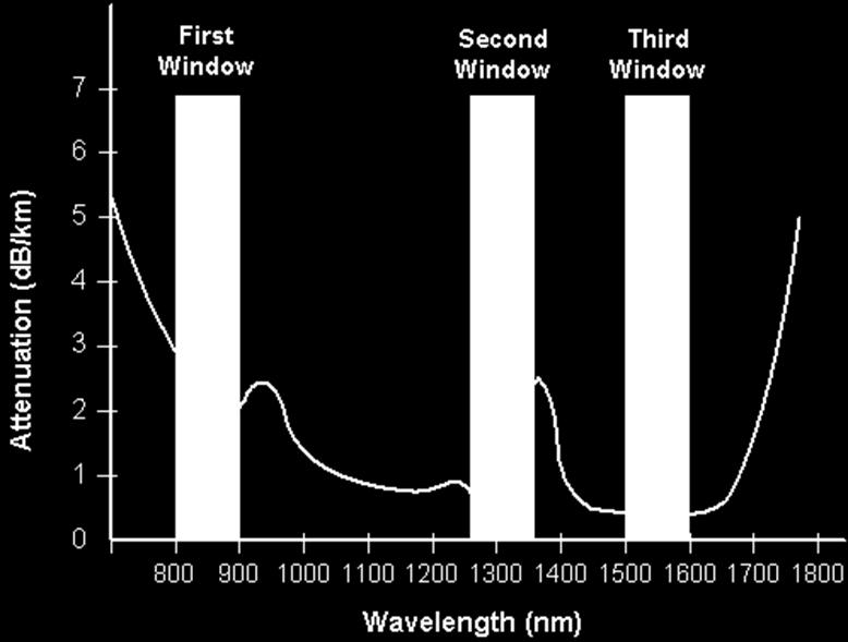
5 Optical fiber Attenuation
 LASER (Light Amplification by Stimulated Emission of")
6 Types of Optical Fiber compatible Sources LED (Light Emitting Diodes) LASER (Light Amplification by Stimulated Emission of Radiation)

7 LEDs Emits incoherent light through spontaneous emission. Used for Multimode systems with Mb/s rates. Broad spectral width and wide output pattern. 850nm region: GaAs and AlGaAs nm region: InGaAsP and InP Two commonly used types: ELEDs and SLEDs
8 Electron diffusion across a pn junction
9 6-1: Light-Emitting Semiconductors Wavelength Direct Band gap- Range Semiconductors like Si (µm) Indirect Band gap- Material Wavelength Range (µm) Bandgap Energy (ev) III V compounds like GaAlAs, GaAsP, InGaAsP Table 6-1: Light-Emitting Semiconductors Bandgap Energy (ev) AlGaInP GaAs AlGaAs InGaAs InGaAsP
10 LED Output Characteristics Typical Powers 1-10 mw Typical beam divergence 120 degrees FWHM Surface emitting LEDs 30 degrees FWHM Edge emitting LEDs Typical wavelength spread nm An Introduction to Fiber Optic Systems-John Powers
11 TYPES of LEDs Edge Emitting LED s Surface Emitting LED s

12 LEDs for FO Communication Coupling lens used to increase efficiency. Short optical Links with Large NA fibers. Data rates less than 20 Mbps.

13 SURFACE EMITTING LED S Coupling lens used to increase efficiency. Short optical Links with Large NA fibers. Data rates less than 20 Mbps.


14 Edge Emitting LED s Edge-emitting Diode: An LED that emits light from its edge, producing more directional output than surface-emitting LED'sthat emit from their top surface. Effective Area: Light is not distributed in the fiber core uniformly. Rather, it follows a distribution that typically peaks in the center of the core and then tails off near the core-cladding interface. It usually extends some short distance into the cladding as well.
15 LED : Specifications of importance Optical Output Power Output Spectrum Light coupling into Fiber Modulation Bandwidth
16 Packaging Microlensed LED

17 Laser Diodes

18 Movie Semiconductor Diode Inventor

19 Commercial Laser for Optical Communications HMV --His Master,s Voice
20

21 LDs Laser Diodes Emit coherent light through stimulated emission Mainly used in Single Mode Systems Light Emission range: 5 to 10 degrees Require Higher complex driver circuitry than LEDs Laser action occurs from three main processes: photon absorption, spontaneous emission, and stimulated emission.
22 Lasing Characteristics Lasing threshold is minimum current that must occur for stimulated emission Any current produced below threshold will result in spontaneous emission only At currents below threshold LDs operate as ELEDs LDs need more current to operate and more current means more complex drive circuitry with higher heat dissipation Laser diodes are much more temperature sensitive than LEDs
23 Semiconductor Laser Diode


24 Current flow Edge emitting lasers Active layers very thin Light emitting area ~ 0.5 µm x 5 µm Diffraction causes rapid beam spread Laser action in Narrow stripe + - Reflective facet - +
25 VCSEL

 Courtesy of")
26 VCSELs and VECSELs vertical-cavity surface-emitting laser (VCSEL) gain material is sandwiched between DBRs (top right) aperture defined in a layer on or in the VCSEL no facet cleaving necessary; VCSELs can be easily mass-produced Courtesy of Keithley Instruments can be made into high-power arrays vertical-external-cavity surface-emitting laser (VECSEL) essentially a VCSEL with one DBR mirror replaced with an external-cavity mirror can be made into high-power arrays external cavity allows for internal frequency-doubling (bottom right) Courtesy of Necsel
27 Resonant cavity VCSEL Vertical cavity surface emitting laser Laser output Mirrors above and below junction Top partly reflective Bottom totally reflecting metal contact n-type substrate (transparent) Output mirror (partly transparent) spacers Junction layer p-type layers blocking layer metal contact
28 Apple awards Finisar $390 million for VCSEL R&D, manufacturing December 14, 2017 Apple says. VCSELs will be used to support smartphone and other consumer product capabilities. For example, VCSELs currently enable Face ID, Animoji and Portrait mode selfies with the iphone X True Depth camera, and other popular Apple features, as well as the proximity-sensing capabilities of AirPods

29 VCSEL LASER Movie


30 Current flow Fiber coupling Fiber butt coupled to lightemitting spot Fiber Light fits in core Light in core Reflective facet 38
31 External cavity laser-2 39
32 Tunable Laser Tunable Laser Employed in broad-band interconnections and broadcast networks where the need for high power, narrow line width, and a tunable single-frequency emission is a must. Laser that is able to produce controllable multiple wavelengths within single cavity. Able to switch transmission of different wavelengths without using multiplexer for transmission to many different channels at by tuning the output frequency to its designated channel.
33 Tunable Laser Operation Current is injected into the Active Region causing the entire optical cavity to oscillate in a single longitudinal mode. A current is then injected into the grating control region causing a refractive index decrease which induces a shift of the Bragg wavelength and variation in the mode. The phase region with the injected phase current allows for recovery in Bragg wavelength in order to keep the same mode in the center of the filter band. This results in an output with variable wavelength.

34 Edge emitter with mirrored facets For a description of cleaving, see Laser Focus World "Alignment and etching techniques assist fabrication of edgeemitting laser diodes," cles/2007/06/laser-diode-fabricationalignment-and-etching-techniquesassist-fabrication-of-edge-emittinglaser-diodes.html gain region is defined within semiconductor, is much wider than it is thick cavity is defined by cleaved facets that are coated to serve as laser mirrors can be single or multiple lateral mode due to rectangular cavity cross-section, single-mode output is elliptical; can be circularized externally by anamorphic optics

35 External-cavity edge emitter one (or both) of the cavity mirrors is external to the LD itself more-complex optomechanical arrangement can achieve narrower linewidths a wavelength-selective element such as a grating can be incorporated for tunability

 for linewidth")
36 Edge-emitting LD with DBR or FBG a distributed Bragg reflector (DBR, above) can be used as a cavity mirror within an edge-emitting LD; adds wavelength stability an optical fiber containing a short section of fiber Bragg grating (FBG, below) can be coupled to an edge-emitting LD for wavelength stability, relative insensitivity to temperature changes or the LD itself can contain a longer, weaker grating that produces distributed feedback (DFB) for linewidth narrowing
37 Source Comparison LDs. LED SLED LD Principle of Light Generation Spontaneous Emission Amplified Spontaneous Emission Stimulated Emission Optical Spectrum Broadband Broadband Narrowband or multiple Fabry-Perot modes Total optical output power Medium Medium High Optical power density Low Medium High Optical waveguide No Yes Yes Light Emittance All directions Divergence-limited Divergence-limited Spatial coherence Low High High Coupling into singlemode fibers Poor Efficient Efficient Temporal coherence Low Low High Generation of speckle noise Low Low High
38 Laser Diode Transmitter
39

40 xample Commercial Transmitter Module Palomar Technologies

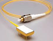
41 Transmitter Packages There are a variety of transmitter packages for different applications. One popular transmitter configuration is the butterfly package. This device has an attached fiber fly lead and components such as the diode laser, a monitoring photodiode, and a thermoelectric cooler. 52
42 Summary Optical light sources convert electrical signals into optical signals and launch them. Commonly used light sources include LEDs, ELEDs, SLEDs, and LDs. LEDs produce nonlinear incoherent light whereas a Laser Diode produces linear coherent light. Incoherent light sources used in multimode systems as where Laser Diodes/Tunable Lasers in single mode systems Laser diodes must operate above their threshold region to produce coherent light, otherwise operating as ELED. Laser diodes are much faster in switching response than LEDs Tunable laser is able to produce coherent light output with controlled variable wavelength Tunable laser is used in multi wavelength systems by replacing a system where many sources are coupled into a multiplexing device system

43 Optical Detectors
44 Requirements of Optical detector High sensitivity at the operating wavelength High Fidelity Large electrical response to the optical signal Short response time to obtain a suitable bandwidth A minimum noise introduced by the detector Stability of performance characteristics Small Size Low bias voltage High reliability Low cost
45 Reverse bias condition
46 Input Output Characteristics of Photodiode Ip(mA) P(mW) Input to a photodiode is light power P Output is current Ip Ip P So Ip=RP where R is responsivity and its value is constant Responsivity R ranges from.5a/w and this characteristics shows how effectively a photodiode convert light into an electrical signal
47 Disadvantages of PN photodiode Narrow depletion Region There is need to increase the width of the depletion region without manipulating unnecessarily the value of the reverse bias voltage.
48 Basic PIN Photodiode Structure Rear Illuminated Photodiode Front Illuminated Photodiode

49 PIN diode Optical Detectors The most common optical detector used with fiber-optic systems is the PIN diode The PIN diode is also operated in the reverse-bias mode As a photodetector, the PIN diode takes advantage of its wide depletion region, in which electrons can create electron-hole pairs The low junction capacitance of the PIN diode allows for very fast switching
50 Advantages of P-I-N photodiode Intrinsic layer is thick, so more number of incident photons enter into this layer and generate electron hole pair, so results in the high quantum efficiency of the device. Reverse biasing voltage is small (usually 50) because the thickness of the depletion region is controlled by the thickness of the intrinsic layer, not by reverse voltage. High bandwidth ( Efforts to improve the bandwidth of 110 Ghz).
51 Wavelength Response Silicon nm Germanium nm GaAs nm InGaAs nm InGaAsP nm 63
52 Detector Sensitivity vs. Wavelength Absorption coefficient vs. Wavelength for several materials (Bowers 1987) Photodiode Responsivity vs. Wavelength for various materials (Albrecht et al 1986)
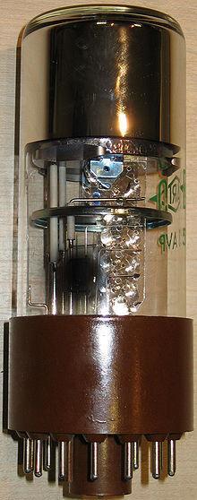
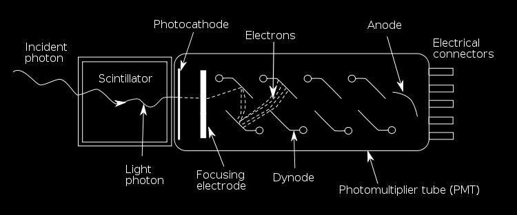
53 Photomultiplier Tube
54 Avalanche Photodiode P + i p N+

55 A P D Drawback of P-I-N photodiode is that it need of an amplifier to magnify the photocurrent produced by the photodiode. The quantum efficiency of the APD is M times larger than that of a P- I-N photo diode. R(APD)=M x R (PIN) M depends upon 1 Accelerating voltage 2 Thickness of the gain region 3 Ratio of electrons to holes participating in the ionization process. M ranges from 10 to 500.
56 Avalanche Photodiodes (APDs) High resistivity p-doped layer increases electric field across absorbing region High-energy electron-hole pairs ionize other sites to multiply the current -Leads to greater sensitivity
57 Noise Sources in photodiode Shot Noise: Deviation of the actual number of electrons from the average numbers is known as shot noise. Thermal Noise The deviation of an instantaneous number of electrons from their average value because of temperature change is called Thermal Noise. Thermal Noise is often called Johnson noise.
58 Johnson (thermal) Noise Noise in a resistor can be modeled as due to a noiseless resistor in parallel with a noise current source The variance of the noise current source is given by: s = i» 2 2 i 4kBTB R Where k B is Boltzman's constant T is the Temperature in Kelvins B is the bandwidth in Hz (not bits/sec)
59 Dark current Noise The dark current noise arises due to dark current which flows in the circuit when the photodiode is in unilluminated environment under bias condition. The magnitude of this current depends on the Operating temperature. Biased voltage Type of detectors Excess Noise: Cause- Avalanche Multiplication Process
60 Receivers Convert optical signals to electronic signals Stages Wavelength-division demultiplexing Detection: optical-to-electronic signals Thresholding, retiming (electronic regeneration) Time-division demultiplexing WDM: must be done before detectors Detectors can't discriminate close wavelengths 74
61 RECEIVERS
62 Receiver Types +Bias +Bias +Bias Rf I s I s I s Output Output Output RL 50 Amplifier RL Ct Amplifier Equalizer Ct Amplifier Low Impedance Low Sensitivity Easily Made Wide Band High Impedance Requires Equalizer for high BW High Sensitivity Low Dynamic Range Careful Equalizer Placement Required Transimpedance High Dynamic Range High Sensitivity Stability Problems Difficult to equalize
63 Receiver Functional Block Diagram Fiber-Optic Communications Technology-Mynbaev & Scheiner
64 Bit Error Rate BER is equal to number of errors divided by total number of pulses (ones and zeros). Total number of pulses is bit rate B times time interval. BER is thus not really a rate, but a unitless probability.
65 Eye Diagrams Eye pattern measurements are made in the time domain and immediately show the effects of waveform distortion on the display screen of standard BER test equipment. The eye opening width defines the time interval over which signals can be sampled without interference from adjacent pulses (ISI). The best sampling time is at the height of the largest eye opening. The eye opening height shows the noise margin or immunity to noise. The rate at which the eye closes gives the sensitivity to timing errors. The rise time is the interval between the 10 and 90% rising-edge points
66 Thank you Chhabra_
67 Bibliography: The excerpts of this lecture are based on the information drawn from following reference. 1. Gerd Keiser, Optical Fiber Communication 3 rd edn., Mc Graw Hill, Djafar K. Mynbaev, Lowell L. Scheiner, Fiber-Optic Communication Technology, LPE, Pearson Education Asia, videos 5.
Optodevice Data Book ODE I. Rev.9 Mar Opnext Japan, Inc.
 Optodevice Data Book ODE-408-001I Rev.9 Mar. 2003 Opnext Japan, Inc. Section 1 Operating Principles 1.1 Operating Principles of Laser Diodes (LDs) and Infrared Emitting Diodes (IREDs) 1.1.1 Emitting Principles
Chapter 3 OPTICAL SOURCES AND DETECTORS
 Chapter 3 OPTICAL SOURCES AND DETECTORS 3. Optical sources and Detectors 3.1 Introduction: The success of light wave communications and optical fiber sensors is due to the result of two technological breakthroughs.
Basic concepts. Optical Sources (b) Optical Sources (a) Requirements for light sources (b) Requirements for light sources (a)
 Optical Sources (a) Requirements for light sources (b) Requirements for light sources (a)") Optical Sources (a) Optical Sources (b) The main light sources used with fibre optic systems are: Light-emitting diodes (LEDs) Semiconductor lasers (diode lasers) Fibre laser and other compact solid-state
Optical Sources (a) Optical Sources (b) The main light sources used with fibre optic systems are: Light-emitting diodes (LEDs) Semiconductor lasers (diode lasers) Fibre laser and other compact solid-state
Lecture 6 Fiber Optical Communication Lecture 6, Slide 1
 Lecture 6 Optical transmitters Photon processes in light matter interaction Lasers Lasing conditions The rate equations CW operation Modulation response Noise Light emitting diodes (LED) Power Modulation
UNIT-III SOURCES AND DETECTORS. According to the shape of the band gap as a function of the momentum, semiconductors are classified as
 UNIT-III SOURCES AND DETECTORS DIRECT AND INDIRECT BAND GAP SEMICONDUCTORS: According to the shape of the band gap as a function of the momentum, semiconductors are classified as 1. Direct band gap semiconductors
Review of Semiconductor Physics
 Review of Semiconductor Physics k B 1.38 u 10 23 JK -1 a) Energy level diagrams showing the excitation of an electron from the valence band to the conduction band. The resultant free electron can freely
Semiconductor Optical Communication Components and Devices Lecture 18: Introduction to Diode Lasers - I
 Semiconductor Optical Communication Components and Devices Lecture 18: Introduction to Diode Lasers - I Prof. Utpal Das Professor, Department of lectrical ngineering, Laser Technology Program, Indian Institute
Laser Diode. Photonic Network By Dr. M H Zaidi
 Laser Diode Light emitters are a key element in any fiber optic system. This component converts the electrical signal into a corresponding light signal that can be injected into the fiber. The light emitter
Introduction Fundamentals of laser Types of lasers Semiconductor lasers
 ECE 5368 Introduction Fundamentals of laser Types of lasers Semiconductor lasers Introduction Fundamentals of laser Types of lasers Semiconductor lasers How many types of lasers? Many many depending on
Optical Receivers Theory and Operation
 Optical Receivers Theory and Operation Photo Detectors Optical receivers convert optical signal (light) to electrical signal (current/voltage) Hence referred O/E Converter Photodetector is the fundamental
White Paper Laser Sources For Optical Transceivers. Giacomo Losio ProLabs Head of Technology
 White Paper Laser Sources For Optical Transceivers Giacomo Losio ProLabs Head of Technology September 2014 Laser Sources For Optical Transceivers Optical transceivers use different semiconductor laser
Examination Optoelectronic Communication Technology. April 11, Name: Student ID number: OCT1 1: OCT 2: OCT 3: OCT 4: Total: Grade:
 Examination Optoelectronic Communication Technology April, 26 Name: Student ID number: OCT : OCT 2: OCT 3: OCT 4: Total: Grade: Declaration of Consent I hereby agree to have my exam results published on
S Optical Networks Course Lecture 2: Essential Building Blocks
 S-72.3340 Optical Networks Course Lecture 2: Essential Building Blocks Edward Mutafungwa Communications Laboratory, Helsinki University of Technology, P. O. Box 2300, FIN-02015 TKK, Finland Tel: +358 9
MAHALAKSHMI ENGINEERING COLLEGE TIRUCHIRAPALLI
 MAHALAKSHMI ENGINEERING COLLEGE TIRUCHIRAPALLI - 621213 DEPARTMENT : ECE SUBJECT NAME : OPTICAL COMMUNICATION & NETWORKS SUBJECT CODE : EC 2402 UNIT III: SOURCES AND DETECTORS PART -A (2 Marks) 1. What
Light Sources, Modulation, Transmitters and Receivers
 Optical Fibres and Telecommunications Light Sources, Modulation, Transmitters and Receivers Introduction Previous section looked at Fibres. How is light generated in the first place? How is light modulated?
Lecture 4 Fiber Optical Communication Lecture 4, Slide 1
 Lecture 4 Optical transmitters Photon processes in light matter interaction Lasers Lasing conditions The rate equations CW operation Modulation response Noise Light emitting diodes (LED) Power Modulation
Optical Amplifiers. Continued. Photonic Network By Dr. M H Zaidi
 Optical Amplifiers Continued EDFA Multi Stage Designs 1st Active Stage Co-pumped 2nd Active Stage Counter-pumped Input Signal Er 3+ Doped Fiber Er 3+ Doped Fiber Output Signal Optical Isolator Optical
Lecture 9 External Modulators and Detectors
 Optical Fibres and Telecommunications Lecture 9 External Modulators and Detectors Introduction Where are we? A look at some real laser diodes. External modulators Mach-Zender Electro-absorption modulators
Detectors for Optical Communications
 Optical Communications: Circuits, Systems and Devices Chapter 3: Optical Devices for Optical Communications lecturer: Dr. Ali Fotowat Ahmady Sep 2012 Sharif University of Technology 1 Photo All detectors
CONTENTS. Chapter 1 Wave Nature of Light 19
 CONTENTS Chapter 1 Wave Nature of Light 19 1.1 Light Waves in a Homogeneous Medium 19 A. Plane Electromagnetic Wave 19 B. Maxwell's Wave Equation and Diverging Waves 22 Example 1.1.1 A diverging laser
Optical Fiber Communication Lecture 11 Detectors
 Optical Fiber Communication Lecture 11 Detectors Warriors of the Net Detector Technologies MSM (Metal Semiconductor Metal) PIN Layer Structure Semiinsulating GaAs Contact InGaAsP p 5x10 18 Absorption InGaAs
Optical Sources and Detectors
 Optical Sources and Detectors 1. Optical Sources Optical transmitter coverts electrical input signal into corresponding optical signal. The optical signal is then launched into the fiber. Optical source
Optical Fibers p. 1 Basic Concepts p. 1 Step-Index Fibers p. 2 Graded-Index Fibers p. 4 Design and Fabrication p. 6 Silica Fibers p.
 Preface p. xiii Optical Fibers p. 1 Basic Concepts p. 1 Step-Index Fibers p. 2 Graded-Index Fibers p. 4 Design and Fabrication p. 6 Silica Fibers p. 6 Plastic Optical Fibers p. 9 Microstructure Optical
21. (i) Briefly explain the evolution of fiber optic system (ii) Compare the configuration of different types of fibers. or 22. (b)(i) Derive modal eq
 Briefly explain the evolution of fiber optic system (ii) Compare the configuration of different types of fibers. or 22. (b)(i) Derive modal eq") Unit-1 Part-A FATIMA MICHAEL COLLEGE OF ENGINEERING & TECHNOLOGY Senkottai Village, Madurai Sivagangai Main Road, Madurai - 625 020. [An ISO 9001:2008 Certified Institution] DEPARTMENT OF ELECTRONICS AND
Unit-1 Part-A FATIMA MICHAEL COLLEGE OF ENGINEERING & TECHNOLOGY Senkottai Village, Madurai Sivagangai Main Road, Madurai - 625 020. [An ISO 9001:2008 Certified Institution] DEPARTMENT OF ELECTRONICS AND
Semiconductor Lasers Semiconductors were originally pumped by lasers or e-beams First diode types developed in 1962: Create a pn junction in
 Semiconductor Lasers Semiconductors were originally pumped by lasers or e-beams First diode types developed in 1962: Create a pn junction in semiconductor material Pumped now with high current density
NEW YORK CITY COLLEGE of TECHNOLOGY
 NEW YORK CITY COLLEGE of TECHNOLOGY THE CITY UNIVERSITY OF NEW YORK DEPARTMENT OF ELECTRICAL AND TELECOMMUNICATIONS ENGINEERING TECHNOLOGY Course : TCET 4102 (TC 700) Fiber-optic communications Module
UNIT III. By Ajay Kumar Gautam Asst. Prof. Electronics & Communication Engineering Dev Bhoomi Institute of Technology & Engineering, Dehradun
 UNIT III By Ajay Kumar Gautam Asst. Prof. Electronics & Communication Engineering Dev Bhoomi Institute of Technology & Engineering, Dehradun SYLLABUS Optical Absorption in semiconductors, Types of Photo
Chapter 1 Introduction
 Chapter 1 Introduction 1-1 Preface Telecommunication lasers have evolved substantially since the introduction of the early AlGaAs-based semiconductor lasers in the late 1970s suitable for transmitting
Semiconductor Lasers Semiconductors were originally pumped by lasers or e-beams First diode types developed in 1962: Create a pn junction in
 Semiconductor Lasers Semiconductors were originally pumped by lasers or e-beams First diode types developed in 1962: Create a pn junction in semiconductor material Pumped now with high current density
Luminous Equivalent of Radiation
 Intensity vs λ Luminous Equivalent of Radiation When the spectral power (p(λ) for GaP-ZnO diode has a peak at 0.69µm) is combined with the eye-sensitivity curve a peak response at 0.65µm is obtained with
BN 1000 May Profile Optische Systeme GmbH Gauss Str. 11 D Karlsfeld / Germany. Tel Fax
 BN 1000 May 2000 Profile Optische Systeme GmbH Gauss Str. 11 D - 85757 Karlsfeld / Germany Tel + 49 8131 5956-0 Fax + 49 8131 5956-99 info@profile-optsys.com www.profile-optsys.com Profile Inc. 87 Hibernia
Functional Materials. Optoelectronic devices
 Functional Materials Lecture 2: Optoelectronic materials and devices (inorganic). Photonic materials Optoelectronic devices Light-emitting diode (LED) displays Photodiode and Solar cell Photoconductive
VERTICAL CAVITY SURFACE EMITTING LASER
 VERTICAL CAVITY SURFACE EMITTING LASER Nandhavel International University Bremen 1/14 Outline Laser action, optical cavity (Fabry Perot, DBR and DBF) What is VCSEL? How does VCSEL work? How is it different
Photodiode: LECTURE-5
 LECTURE-5 Photodiode: Photodiode consists of an intrinsic semiconductor sandwiched between two heavily doped p-type and n-type semiconductors as shown in Fig. 3.2.2. Sufficient reverse voltage is applied
Vertical External Cavity Surface Emitting Laser
 Chapter 4 Optical-pumped Vertical External Cavity Surface Emitting Laser The booming laser techniques named VECSEL combine the flexibility of semiconductor band structure and advantages of solid-state
Optical Communications
 Optical Communications Telecommunication Engineering School of Engineering University of Rome La Sapienza Rome, Italy 2005-2006 Lecture #4, May 9 2006 Receivers OVERVIEW Photodetector types: Photodiodes
is a method of transmitting information from one place to another by sending light through an optical fiber. The light forms an electromagnetic
 is a method of transmitting information from one place to another by sending light through an optical fiber. The light forms an electromagnetic carrier wave that is modulated to carry information. The
InP-based Waveguide Photodetector with Integrated Photon Multiplication
 InP-based Waveguide Photodetector with Integrated Photon Multiplication D.Pasquariello,J.Piprek,D.Lasaosa,andJ.E.Bowers Electrical and Computer Engineering Department University of California, Santa Barbara,
Optoelectronics ELEC-E3210
 Optoelectronics ELEC-E3210 Lecture 4 Spring 2016 Outline 1 Lateral confinement: index and gain guiding 2 Surface emitting lasers 3 DFB, DBR, and C3 lasers 4 Quantum well lasers 5 Mode locking P. Bhattacharya:
Figure Responsivity (A/W) Figure E E-09.
 Figure E E-09.") OSI Optoelectronics, is a leading manufacturer of fiber optic components for communication systems. The products offer range for Silicon, GaAs and InGaAs to full turnkey solutions. Photodiodes are semiconductor
OSI Optoelectronics, is a leading manufacturer of fiber optic components for communication systems. The products offer range for Silicon, GaAs and InGaAs to full turnkey solutions. Photodiodes are semiconductor
EE119 Introduction to Optical Engineering Spring 2003 Final Exam. Name:
 EE119 Introduction to Optical Engineering Spring 2003 Final Exam Name: SID: CLOSED BOOK. THREE 8 1/2 X 11 SHEETS OF NOTES, AND SCIENTIFIC POCKET CALCULATOR PERMITTED. TIME ALLOTTED: 180 MINUTES Fundamental
Elements of Optical Networking
 Bruckner Elements of Optical Networking Basics and practice of optical data communication With 217 Figures, 13 Tables and 93 Exercises Translated by Patricia Joliet VIEWEG+ TEUBNER VII Content Preface
Visible Superluminescent LEDs for Smart Lighting
 Visible Superluminescent LEDs for Smart Lighting M. Duelk, M.Rossetti, A. Castiglia, M. Malinverni, N. Matuschek, C. Vélez EXALOS AG, 8952 Schlieren, Switzerland J.-F. Carlin, N. Grandjean Ecole Polytechnique
ECE 340 Lecture 29 : LEDs and Lasers Class Outline:
 ECE 340 Lecture 29 : LEDs and Lasers Class Outline: Light Emitting Diodes Lasers Semiconductor Lasers Things you should know when you leave Key Questions What is an LED and how does it work? How does a
Key Questions. What is an LED and how does it work? How does a laser work? How does a semiconductor laser work? ECE 340 Lecture 29 : LEDs and Lasers
 Things you should know when you leave Key Questions ECE 340 Lecture 29 : LEDs and Class Outline: What is an LED and how does it How does a laser How does a semiconductor laser How do light emitting diodes
Lecture 18: Photodetectors
 Lecture 18: Photodetectors Contents 1 Introduction 1 2 Photodetector principle 2 3 Photoconductor 4 4 Photodiodes 6 4.1 Heterojunction photodiode.................... 8 4.2 Metal-semiconductor photodiode................
Figure Figure E E-09. Dark Current (A) 1.
 1.") OSI Optoelectronics, is a leading manufacturer of fiber optic components for communication systems. The products offer range for Silicon, GaAs and InGaAs to full turnkey solutions. Photodiodes are semiconductor
OSI Optoelectronics, is a leading manufacturer of fiber optic components for communication systems. The products offer range for Silicon, GaAs and InGaAs to full turnkey solutions. Photodiodes are semiconductor
R. J. Jones Optical Sciences OPTI 511L Fall 2017
 R. J. Jones Optical Sciences OPTI 511L Fall 2017 Semiconductor Lasers (2 weeks) Semiconductor (diode) lasers are by far the most widely used lasers today. Their small size and properties of the light output
Lecture 1: Course Overview. Rajeev J. Ram
 Lecture 1: Course Overview Rajeev J. Ram Office: 36-491 Telephone: X3-4182 Email: rajeev@mit.edu Syllabus Basic concepts Advanced concepts Background: p-n junctions Photodetectors Modulators Optical amplifiers
EE 230: Optical Fiber Communication Transmitters
 EE 230: Optical Fiber Communication Transmitters From the movie Warriors of the Net Laser Diode Structures Most require multiple growth steps Thermal cycling is problematic for electronic devices Fabry
Absorption: in an OF, the loss of Optical power, resulting from conversion of that power into heat.
 Absorption: in an OF, the loss of Optical power, resulting from conversion of that power into heat. Scattering: The changes in direction of light confined within an OF, occurring due to imperfection in
Chap14. Photodiode Detectors
 Chap14. Photodiode Detectors Mohammad Ali Mansouri-Birjandi mansouri@ece.usb.ac.ir mamansouri@yahoo.com Faculty of Electrical and Computer Engineering University of Sistan and Baluchestan (USB) Design
Ph 77 ADVANCED PHYSICS LABORATORY ATOMIC AND OPTICAL PHYSICS
 Ph 77 ADVANCED PHYSICS LABORATORY ATOMIC AND OPTICAL PHYSICS Diode Laser Characteristics I. BACKGROUND Beginning in the mid 1960 s, before the development of semiconductor diode lasers, physicists mostly
Instruction manual and data sheet ipca h
 1/15 instruction manual ipca-21-05-1000-800-h Instruction manual and data sheet ipca-21-05-1000-800-h Broad area interdigital photoconductive THz antenna with microlens array and hyperhemispherical silicon
Fabrication of High-Speed Resonant Cavity Enhanced Schottky Photodiodes
 Fabrication of High-Speed Resonant Cavity Enhanced Schottky Photodiodes Abstract We report the fabrication and testing of a GaAs-based high-speed resonant cavity enhanced (RCE) Schottky photodiode. The
OPTI510R: Photonics. Khanh Kieu College of Optical Sciences, University of Arizona Meinel building R.626
 OPTI510R: Photonics Khanh Kieu College of Optical Sciences, University of Arizona kkieu@optics.arizona.edu Meinel building R.626 Photodetectors Introduction Most important characteristics Photodetector
Optical communications
 Optical communications Components and enabling technologies Optical networking Evolution of optical networking: road map SDH = Synchronous Digital Hierarchy SONET = Synchronous Optical Network SDH SONET
Optical Communication and Networks M.N. Bandyopadhyay
 Optical Communication and Networks M.N. Bandyopadhyay Director National Institute of Technology (NIT) Calicut Delhi-110092 2014 OPTICAL COMMUNICATION AND NETWORKS M.N. Bandyopadhyay 2014 by PHI Learning
Physics of Waveguide Photodetectors with Integrated Amplification
 Physics of Waveguide Photodetectors with Integrated Amplification J. Piprek, D. Lasaosa, D. Pasquariello, and J. E. Bowers Electrical and Computer Engineering Department University of California, Santa
Tutorial. Various Types of Laser Diodes. Low-Power Laser Diodes
 371 Introduction In the past fifteen years, the commercial and industrial use of laser diodes has dramatically increased with some common applications such as barcode scanning and fiber optic communications.
2 in the multipath dispersion of the optical fibre. (b) Discuss the merits and drawbacks of cut bouls method of measurement of alternation.
 Discuss the merits and drawbacks of cut bouls method of measurement of alternation.") B.TECH IV Year I Semester (R09) Regular Examinations, November 2012 1 (a) Derive an expression for multiple time difference tt 2 in the multipath dispersion of the optical fibre. (b) Discuss the merits
B.TECH IV Year I Semester (R09) Regular Examinations, November 2012 1 (a) Derive an expression for multiple time difference tt 2 in the multipath dispersion of the optical fibre. (b) Discuss the merits
InP-based Waveguide Photodetector with Integrated Photon Multiplication
 InP-based Waveguide Photodetector with Integrated Photon Multiplication D.Pasquariello,J.Piprek,D.Lasaosa,andJ.E.Bowers Electrical and Computer Engineering Department University of California, Santa Barbara,
Comparative Study of an Optical Link with PIN and APD as Photo-Detector Preetam Jain 1, Dr Lochan Jolly 2
 Comparative Study of an Optical Link with PIN and APD as Photo-Detector Preetam Jain 1, Dr Lochan Jolly 2 1 ME EXTC Student Thakur College of Engineering and Technology 2 Professor Thakur College of Engineering
FIBER OPTICS. Prof. R.K. Shevgaonkar. Department of Electrical Engineering. Indian Institute of Technology, Bombay. Lecture: 18.
 FIBER OPTICS Prof. R.K. Shevgaonkar Department of Electrical Engineering Indian Institute of Technology, Bombay Lecture: 18 Optical Sources- Introduction to LASER Diodes Fiber Optics, Prof. R.K. Shevgaonkar,
IST IP NOBEL "Next generation Optical network for Broadband European Leadership"
 DBR Tunable Lasers A variation of the DFB laser is the distributed Bragg reflector (DBR) laser. It operates in a similar manner except that the grating, instead of being etched into the gain medium, is
Spatial Investigation of Transverse Mode Turn-On Dynamics in VCSELs
 Spatial Investigation of Transverse Mode Turn-On Dynamics in VCSELs Safwat W.Z. Mahmoud Data transmission experiments with single-mode as well as multimode 85 nm VCSELs are carried out from a near-field
Optical MEMS in Compound Semiconductors Advanced Engineering Materials, Cal Poly, SLO November 16, 2007
 Optical MEMS in Compound Semiconductors Advanced Engineering Materials, Cal Poly, SLO November 16, 2007 Outline Brief Motivation Optical Processes in Semiconductors Reflectors and Optical Cavities Diode
Optical Amplifiers Photonics and Integrated Optics (ELEC-E3240) Zhipei Sun Photonics Group Department of Micro- and Nanosciences Aalto University
 Zhipei Sun Photonics Group Department of Micro- and Nanosciences Aalto University") Photonics Group Department of Micro- and Nanosciences Aalto University Optical Amplifiers Photonics and Integrated Optics (ELEC-E3240) Zhipei Sun Last Lecture Topics Course introduction Ray optics & optical
Photonics Group Department of Micro- and Nanosciences Aalto University Optical Amplifiers Photonics and Integrated Optics (ELEC-E3240) Zhipei Sun Last Lecture Topics Course introduction Ray optics & optical
Wavelength switching using multicavity semiconductor laser diodes
 Wavelength switching using multicavity semiconductor laser diodes A. P. Kanjamala and A. F. J. Levi Department of Electrical Engineering University of Southern California Los Angeles, California 989-1111
PHYSICAL ELECTRONICS(ECE3540) APPLICATIONS OF PHYSICAL ELECTRONICS PART I
 APPLICATIONS OF PHYSICAL ELECTRONICS PART I") PHYSICAL ELECTRONICS(ECE3540) APPLICATIONS OF PHYSICAL ELECTRONICS PART I Tennessee Technological University Monday, October 28, 2013 1 Introduction In the following slides, we will discuss the summary
PHYSICAL ELECTRONICS(ECE3540) APPLICATIONS OF PHYSICAL ELECTRONICS PART I Tennessee Technological University Monday, October 28, 2013 1 Introduction In the following slides, we will discuss the summary
Coherent Receivers Principles Downconversion
 Coherent Receivers Principles Downconversion Heterodyne receivers mix signals of different frequency; if two such signals are added together, they beat against each other. The resulting signal contains
Lecture 14: Photodiodes
 Lecture 14: Photodiodes Background concepts p-n photodiodes photoconductive/photovoltaic modes p-i-n photodiodes responsivity and bandwidth Reading: Senior 8.1-8.8.3 Keiser Chapter 6 1 Electron-hole photogeneration
Fiber-Optic Communication Systems
 Fiber-Optic Communication Systems Second Edition GOVIND P. AGRAWAL The Institute of Optics University of Rochester Rochester, NY A WILEY-iNTERSCIENCE PUBLICATION JOHN WILEY & SONS, INC. NEW YORK / CHICHESTER
OFCS OPTICAL DETECTORS 11/9/2014 LECTURES 1
 OFCS OPTICAL DETECTORS 11/9/2014 LECTURES 1 1-Defintion & Mechanisms of photodetection It is a device that converts the incident light into electrical current External photoelectric effect: Electrons are
Spontaneous Hyper Emission: Title of Talk
 Spontaneous Hyper Emission: Title of Talk Enhanced Light Emission by Optical Antennas Ming C. Wu University of California, Berkeley A Science & Technology Center Where Our Paths Crossed Page Nanopatch
High brightness semiconductor lasers M.L. Osowski, W. Hu, R.M. Lammert, T. Liu, Y. Ma, S.W. Oh, C. Panja, P.T. Rudy, T. Stakelon and J.E.
 QPC Lasers, Inc. 2007 SPIE Photonics West Paper: Mon Jan 22, 2007, 1:20 pm, LASE Conference 6456, Session 3 High brightness semiconductor lasers M.L. Osowski, W. Hu, R.M. Lammert, T. Liu, Y. Ma, S.W. Oh,
UNIT - 5 OPTICAL RECEIVER
 UNIT - 5 LECTURE-1 OPTICAL RECEIVER Introduction, Optical Receiver Operation, receiver sensitivity, quantum limit, eye diagrams, coherent detection, burst mode receiver operation, Analog receivers. RECOMMENDED
Photonics and Optical Communication
 Photonics and Optical Communication (Course Number 300352) Spring 2007 Dr. Dietmar Knipp Assistant Professor of Electrical Engineering http://www.faculty.iu-bremen.de/dknipp/ 1 Photonics and Optical Communication
2.5GBPS 850NM VCSEL LC TOSA PACKAGE
 DATA SHEET LC TOSA PACKAGE FEATURES: 850nm multi-mode oxide isolated VCSEL Extended Temperature Range Operation ( 40 to +85 deg operating range) Capable of modulation operation from DC to 2.5Gbps TO-46
Optical switches. Switching Technology S Optical switches
 Optical switches Switching Technology S38.165 http://www.netlab.hut.fi/opetus/s38165 13-1 Optical switches Components and enabling technologies Contention resolution Optical switching schemes 13-2 1 Components
Application Instruction 002. Superluminescent Light Emitting Diodes: Device Fundamentals and Reliability
 I. Introduction II. III. IV. SLED Fundamentals SLED Temperature Performance SLED and Optical Feedback V. Operation Stability, Reliability and Life VI. Summary InPhenix, Inc., 25 N. Mines Road, Livermore,
LEDs, Photodetectors and Solar Cells
 LEDs, Photodetectors and Solar Cells Chapter 7 (Parker) ELEC 424 John Peeples Why the Interest in Photons? Answer: Momentum and Radiation High electrical current density destroys minute polysilicon and
ECE 4606 Undergraduate Optics Lab Interface circuitry. Interface circuitry. Outline
 Interface circuitry Interface circuitry Outline Photodiode Modifying capacitance (bias, area) Modifying resistance (transimpedance amp) Light emitting diode Direct current limiting Modulation circuits
Lecture 4 INTEGRATED PHOTONICS
 Lecture 4 INTEGRATED PHOTONICS What is photonics? Photonic applications use the photon in the same way that electronic applications use the electron. Devices that run on light have a number of advantages
VCSEL Based Optical Sensors
 VCSEL Based Optical Sensors Jim Guenter and Jim Tatum Honeywell VCSEL Products 830 E. Arapaho Road, Richardson, TX 75081 (972) 470 4271 (972) 470 4504 (FAX) Jim.Guenter@Honeywell.com Jim.Tatum@Honeywell.com
Vertical Cavity Surface Emitting Laser (VCSEL) Technology
 Technology") Vertical Cavity Surface Emitting Laser (VCSEL) Technology Gary W. Weasel, Jr. (gww44@msstate.edu) ECE 6853, Section 01 Dr. Raymond Winton Abstract Vertical Cavity Surface Emitting Laser technology, typically
Vertical Cavity Surface Emitting Laser (VCSEL) Technology Gary W. Weasel, Jr. (gww44@msstate.edu) ECE 6853, Section 01 Dr. Raymond Winton Abstract Vertical Cavity Surface Emitting Laser technology, typically
Vixar High Power Array Technology
 Vixar High Power Array Technology I. Introduction VCSELs arrays emitting power ranging from 50mW to 10W have emerged as an important technology for applications within the consumer, industrial, automotive
Ring cavity tunable fiber laser with external transversely chirped Bragg grating
 Ring cavity tunable fiber laser with external transversely chirped Bragg grating A. Ryasnyanskiy, V. Smirnov, L. Glebova, O. Mokhun, E. Rotari, A. Glebov and L. Glebov 2 OptiGrate, 562 South Econ Circle,
High-power semiconductor lasers for applications requiring GHz linewidth source
 High-power semiconductor lasers for applications requiring GHz linewidth source Ivan Divliansky* a, Vadim Smirnov b, George Venus a, Alex Gourevitch a, Leonid Glebov a a CREOL/The College of Optics and
14.2 Photodiodes 411
 14.2 Photodiodes 411 Maximum reverse voltage is specified for Ge and Si photodiodes and photoconductive cells. Exceeding this voltage can cause the breakdown and severe deterioration of the sensor s performance.
Fundamentals of Laser
 SMR 1826-3 Preparatory School to the Winter College on Fibre 5-9 February 2007 Fundamentals of Laser Imrana Ashraf Zahid Quaid-i-Azam University Islamabad Pakistan Fundamentals of Laser Dr. Imrana Ashraf
SYLLABUS Optical Fiber Communication
 SYLLABUS Optical Fiber Communication Subject Code : IA Marks : 25 No. of Lecture Hrs/Week : 04 Exam Hours : 03 Total no. of Lecture Hrs. : 52 Exam Marks : 100 UNIT - 1 PART - A OVERVIEW OF OPTICAL FIBER
Diode Lasers, Single- Mode 50 to 200 mw, 830/852 nm. 54xx Series
 Diode Lasers, Single- Mode 50 to 200 mw, 830/852 nm 54xx Series www.lumentum.com Data Sheet Diode Lasers, Single-Mode 50 to 200 mw,830/852 nm High-resolution applications including optical data storage,
Micro-sensors - what happens when you make "classical" devices "small": MEMS devices and integrated bolometric IR detectors
 Micro-sensors - what happens when you make "classical" devices "small": MEMS devices and integrated bolometric IR detectors Dean P. Neikirk 1 MURI bio-ir sensors kick-off 6/16/98 Where are the targets
Optoelectronics EE/OPE 451, OPT 444 Fall 2009 Section 1: T/Th 9:30-10:55 PM
 Optoelectronics EE/OPE 451, OPT 444 Fall 009 Section 1: T/Th 9:30-10:55 PM John D. Williams, Ph.D. Department of Electrical and Computer Engineering 406 Optics Building - UAHuntsville, Huntsville, AL 35899
3550 Aberdeen Ave SE, Kirtland AFB, NM 87117, USA ABSTRACT 1. INTRODUCTION
 Beam Combination of Multiple Vertical External Cavity Surface Emitting Lasers via Volume Bragg Gratings Chunte A. Lu* a, William P. Roach a, Genesh Balakrishnan b, Alexander R. Albrecht b, Jerome V. Moloney
High-frequency tuning of high-powered DFB MOPA system with diffraction limited power up to 1.5W
 High-frequency tuning of high-powered DFB MOPA system with diffraction limited power up to 1.5W Joachim Sacher, Richard Knispel, Sandra Stry Sacher Lasertechnik GmbH, Hannah Arendt Str. 3-7, D-3537 Marburg,
NON-AMPLIFIED PHOTODETECTOR USER S GUIDE
 NON-AMPLIFIED PHOTODETECTOR USER S GUIDE Thank you for purchasing your Non-amplified Photodetector. This user s guide will help answer any questions you may have regarding the safe use and optimal operation
Optical Fibre Communication Systems
 Optical Fibre Communication Systems Lecture 4 - Detectors & Receivers Professor Z Ghassemlooy Northumbria Communications Laboratory Faculty of Engineering and Environment The University of Northumbria
RECENTLY, using near-field scanning optical
 1 2 1 2 Theoretical and Experimental Study of Near-Field Beam Properties of High Power Laser Diodes W. D. Herzog, G. Ulu, B. B. Goldberg, and G. H. Vander Rhodes, M. S. Ünlü L. Brovelli, C. Harder Abstract