User's Guide Model 26 Cryogenic Temperature Controller
|
|
|
- Alberta Powers
- 5 years ago
- Views:
Transcription
1 User's Guide Model 26 Cryogenic Temperature Controller CRYOGENIC CONTROL SYSTEMS, INC. P.O. Box 7012 Rancho Santa Fe, CA Tel: (858) Fax: (858)
2 Copyright Cryogenic Control Systems, Inc. All Rights Reserved. Printing History Edition 1d. Certification Cryogenic Control Systems, Inc. (Cryo-con) certifies that this product met its published specifications at the time of shipment. Cryo-con further certifies that its calibration measurements are traceable to the United States National Institute of Standards and Technology (NIST). Warranty This product is warranted against defects in materials and workmanship for a period of one year from date of shipment. During this period Cryo-con will, at its option, either repair or replace products which prove to be defective. For products returned to Cryo-con for warranty service, the Buyer shall prepay shipping charges and Cryo-con shall pay shipping charges to return the product to the Buyer. However, the Buyer shall pay all shipping charges, duties, and taxes for products returned to Cryo-con from another country. Warranty Service For warranty service or repair, this product must be returned to a service facility designated by Cryo-con. Limitation of Warranty The foregoing warranty shall not apply to defects resulting from improper or inadequate maintenance by the Buyer, Buyer supplied products or interfacing, unauthorized modification or misuse, operation outside of the environmental specifications for the product, or improper site preparation or maintenance. The design and implementation of any circuit on this product is the sole responsibility of the Buyer. Cryo-con does not warrant the Buyer's circuitry or malfunctions of this product that result from the Buyer's circuitry. In addition Cryo-con does not warrant any damage that occurs as a result of the Buyer's circuit or any defects that result from Buyersupplied products. Notice Information contained in this document is subject to change without notice. Cryo-con makes no warranty of any kind with regard to this material, including, but not limited to, the implied warranties of merchantability and fitness for a particular purpose. Cryo-con shall not be liable for errors contained herein or for incidental or consequential damages in connection with the furnishing, performance, or use of this material. No part of this document may be photocopied, reproduced, electronically transferred, or translated to another language without prior written consent. Trademark Acknowledgement CalGen and Cryo-Con are registered trademarks of Cryogenic Control Systems, Inc. All other product and company names are trademarks or trade names of their respective companies. Safety The Model 26 does not contain any user serviceable parts. Do not open the enclosure. Do not install substitute parts or perform any unauthorized modification to the product. For service or repair, return the product to Cryo-con or an authorized service center.
3 Table of Contents Introduction...1 Sensor Inputs...1 Control Loops...2 User Interface...3 Remote Control...4 Preparing the controller for use...7 Supplied Items...7 Verify the AC Power Line Voltage Selection...7 Apply Power to the Controller...7 Installation...8 Initial Setup and Configuration...10 Options and Accessories...12 Returning Equipment...14 A Quick Start Guide to the User Interface...15 Specifications, Features and Functions...19 Specification Summary...19 Performance Summary...24 Input Channel Characteristics...27 Control Loop Outputs...31 Remote Interfaces...33 Rear Panel...34 Mechanical, Form Factors and Environmental...35 Front Panel Operation...37 The Keypad...37 The Front Panel Display...42 Front Panel Menu Operation...47 Instrument Setup Menus...47 Basic Setup and Operation...67 Configuring a Sensor...67 Using NTC Resistor Sensors...67 Using PTC resistor sensors...68 Downloading a Sensor Calibration Curve...69 Autotuning...72 Temperature Ramping...77 Cryocooler Signature Subtraction...78 Using an external power booster...80 Using CalGen...80 Using Thermocouple Sensors...84 System Shielding and Grounding Issues...89 Instrument Calibration...91 Cryo-con Calibration Services...91 Calibration Interval...91 Remote Operation...92 Remote Interface Configuration...92 iii
4 Remote Programming Guide...95 General Overview...95 An Introduction to the SCPI Language...96 Remote Command Tree Remote Command Descriptions Code snippet in C EU Declaration of Conformity Appendix A: Installed Sensor Curves Factory Installed Curves User Installed Sensor Curves Sensor Curves on CD User Calibration Curve File Format Appendix B: Updating Instrument Firmware Discussion Updating unit firmware Appendix C: Troubleshooting Guide Error Displays Control Loop and Heater Problems Temperature Measurement Errors Remote I/O problems General problems Appendix D: Tuning Control Loops Introduction Various methods for obtaining PID coefficients Manual Tuning Procedures Appendix E: Sensor Data Cryo-con S700 Silicon Diode Cryo-con S900 Silicon Diode Sensor Packages Appendix F: Configuration Scripts Script File Structure Script File Example Appendix G: Sensor Data Tables Silicon Diode Platinum RTD Rhodium-Iron Cryogenic Linear Temperature Sensor (CLTS) Cernox Ruthenium-Oxide Appendix H: Rear Panel Connections Sensor Connections Control Loop #1 Connections Control Loop #2 and Relay Connections Ethernet (LAN) Connection IEEE Connections USB Connections Index iv
5 Index of Figures Figure 1: Rack Mount Kit...8 Figure 2: Rack Mount Kit...9 Figure 3: Model 26 Rear Panel Layout...34 Figure 4: Model 26 Front Panel Layout...37 Figure 5: Thermocouple Module...84 Figure 6: Thermocouple Switches...84 Figure 7: Proper Assembly of the Input Connector Figure 8: Diode and Resistor Sensor Connections v
6 Index of Tables Table 1: Model 26 Instrument Accessories...12 Table 2: Cryogenic Accessories...13 Table 3: Loop #1 Output Summary...16 Table 4: Control Type Summary...16 Table 5: Supported Sensor Types...19 Table 6: Accuracy and Resolution for PTC Resistors...20 Table 7: 10mV Constant-Voltage Accuracy Specifications...21 Table 8: Supported Sensor Configurations...27 Table 9: PTC Resistor Sensor Configuration...28 Table 10: Loop 1 Heater output ranges...31 Table 11: Loop 2 Heater output ranges...32 Table 12: Keypad key functions...41 Table 13: Temperature Units...43 Table 14: Input Channel Configuration Menu...48 Table 15: Control Loop Setup Menus...51 Table 16: User Configurations Menu...53 Table 17: System Configuration Menu...54 Table 18: Over Temperature Disconnect Configuration...56 Table 19: Network Configuration Menu...58 Table 20: PID Table Edit Menu...60 Table 21: Sensor Setup Menu...61 Table 22: Calibration Curve Menu...62 Table 23: Auto Tune Menu...63 Table 24: digital output Status Indicators...65 Table 25: Digital Output Modes...65 Table 26: Recommended Sensor Configuration Data...70 Table 27: Autotune Menu...75 Table 28: Autotune States...76 Table 29: First CalGen Menu, Diode Sensor...82 Table 30: CalGen Menu, 2-point Diode Sensor...82 Table 31: CalGen New Curve Menu...83 Table 32: Thermocouple Polarities...86 Table 33: GPIB Host Setup Parameters...93 Table 34: BB Package Specifications Table 35: Input Connector Pin-out Table 36: Sensor Cable Color Codes Table 37: Loop 1 Connections Table 38: Loop #2 and Digital Output Connections vi
7 Introduction Introduction The model 26 cryogenic temperature controller was designed for applications requiring high output power while still supporting a wide range of temperature sensors. Four inputs and four independent control loops provide a total output power of 150W. Each input is independent and capable of temperature measurement to 500mK with an appropriate temperature sensor. The Model 26 supports virtually any cryogenic temperature sensor produced by any manufacturer. The four control loop outputs feature a primary 100W heater, a secondary heater of 50W and two 10-Volt non-powered outputs. All control modes are supported by all outputs. The 26 front panel incorporates a large high resolution graphics TFT type Liquid Crystal Display with an exceptionally wide viewing angle. With it's bright white LED back-light, complete instrument status can be seen at a glance, even from across the room. Sensor Inputs The Model 26 has four identical input channels, each of which implements a ratiometric AC resistance bridge. This bridge uses separate, balanced circuits to simultaneously measure both the voltage drop across the temperature sensor and the current flowing through it. By measuring current with a higher accuracy than it can be set, precision resistance measurements are obtained, even at low excitation levels. Negative-Temperature-Coefficient (NTC) resistors are often used as low temperature thermometers, especially at ultra-low temperature. Examples include Rutheniumoxide, Carbon-Glass, Cernox, Carbon-Ceramic, Germanium and several others. Their resistance and sensitivity increase dramatically at low temperature but their sensitivity is usually poor at warmer temperatures. The Model 26 provides robust support for NTC resistor sensors by using constantvoltage AC excitation. In the warm region where the sensor has low resistance and low sensitivity, constant-voltage will apply a high excitation current to improve measurement accuracy. At low temperature where the sensor has high sensitivity and high resistance, measurement errors are dominated by sensor self-heating. Constant-voltage excitation reduces this error by reducing power dissipated in the sensor as temperature decreases. A common source of error at ultra-low temperature is sensor self-heating due to DC offsets in the measurement electronics. The Model 26 resistance bridge measures the actual current flowing through the sensor to actively cancel DC offsets by using a feedback loop to offset it's excitation source. Low temperature systems can be negatively affected by coarse steps in excitation current. The Model 26 prevents this by using a step-less, continuously variable excitation source. 1
8 Introduction Positive Temperature Coefficient (PTC) resistor sensors including Platinum, CLTS and Rhodium-Iron RTDs use the resistance bridge in a constant-current, AC mode. Platinum RTD sensors use a built-in DIN standard calibration curve that has been extended to 14K for cryogenic use. Lower temperature use is possible with custom calibrations. Thermocouple sensors are supported by using an optional thermocouple module that plugs into any of the Model 26's input channels. Up to four modules can be connected to a single instrument. For all sensor types, conversion of a sensor reading into temperature is performed by using a Cubic Spline interpolation algorithm. In addition to providing higher accuracy than conventional linear interpolation, the spline function eliminates discontinuities during temperature ramps or sweeps by ensuring that the first and second derivatives are continuous. Control Loops There are four independent control loop outputs: 1. Loop #1 heater output is a linear, low noise RFI filtered current source that can provide up to 1.0 Ampere into 50 resistive loads or 2.0 Ampere into 25 loads. Four full-scale ranges are available in decade increments down to 500mW full-scale. 2. Loop #2 is a linear heater with three output ranges of 50-Watts and 5-Watt and 500mW full-scale into a 50 load. 3. Loop #3 and #4 are a non-powered analog voltage output intended to control an external booster power supply. Output is selectable at 10 or 5 Volts full scale. 2
9 Introduction User Interface The Model 26 s user interface consists of a large, bright TFT type Liquid Crystal Display and a full 21-key keypad. In this user-friendly interface, all features and functions of the instrument can be accessed via this simple and intuitive menu driven interface. The Home screen projects four user configurable zones that allow the real-time display of all input channel, control loop and instrument status information. From this screen, accessing any of the instrument's configuration menus requires only the press of a single key. As always, convenient names can be assigned to input channels. Cryo-con's innovative instrument configuration menus show real-time status information so the user can instantly view the results of any changes made. On the control loop menu, the controlling source temperature, heater range and power output level can be observed while tuning a loop. An essential feature for debugging system software is the Network Configuration Menu's ability to show remote commands as they are sent and received to the instrument. 1A:Sample Holder Loop 1A:Sample Holder Set Pt: K Pgain: Igain: 60.00S Dgain: 7.500/S Pman: % Type: RampT Input: ChA 2B:First Stage K K K 1-Off-Low K 2-Off-Low C:Second Stage D:Rad Shield K 4.845K RO-600 RuOx 10mV Ä R500 RuOx 10mV A: K Ramp 42% of Mid Range: MID PID Table index: 2 Next Network Configuration Menu Dev: M DHCP Ena: On Msk: :50:C2:6F:40:3C IP: GWy: >input a:temp?;units?;name?;sys:time? <0.5321;K;Sample Holder;14:37:25. Sensor Curves: The Model 26 includes built-in curves that support most industry standard temperature sensors. Additionally, eight user calibration curves are available for custom or calibrated sensors. Each user curve may have up to 200 entries and are entered from the front panel, or transferred via any of the available remote interfaces. New calibration curves may be generated using the CalGen feature to fit any existing diode, Platinum or NTC resistor calibration curve at up to three user specified temperature points. This provides an easy and effective method for obtaining higher accuracy temperature measurements without expensive sensor calibrations. 3
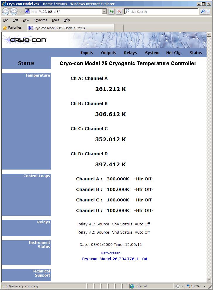
10 Introduction Data logging is performed by continuously recording to an internal 1,365 entry circular buffer. Data is time stamped so that the actual time of an event can be determined. Non-volatile memory is used so that data will survive a power failure. Input Channel Statistics: The Model 26 continuously tracks temperature history independently on each input channel and provides a statistical summary that indicates the channel's minimum, maximum, average and standard deviation. Also shown are the slope and the offset of the best-fit straight line of temperature history data. Alarms: Visual, remote and audible alarms are independently programmed to assert, or clear based on high or low temperature condition, or a detected sensor fault. Latched alarms are asserted on an alarm condition and will remain asserted until cleared by the user. Relays: The Model 26 has two 10-Ampere dry-contact relays. These can be used to control a refrigerator system or other external equipment. Each relay can be asserted or cleared based on the temperature reading of a selected input channel. High and low setpoints may be set from the front panel or a remote interface. Furthermore, the relays can be manually asserted ON or OFF. Remote Control Standard Remote Interfaces include Ethernet and USB. IEEE-488.2(GPIB) is optional. The Model 26 connects directly to any Ethernet Local-Area-Network (LAN) to make measurements easily and economically. TCP/IP and UDP data port servers brings fast Ethernet connectivity to all common data acquisition software programs including LabView. An ASCII text based command language identical to those commonly used with GPIB or RS-232 interfaces is implemented. This is the primary way that user software interfaces to the instrument. Using the Ethernet SMTP protocol, the controller will send based on selected alarm conditions. is configured by using the web page interface. Using the Ethernet HTTP protocol, the instrument s embedded web server allows the instrument to be viewed and configured from any web browser. 4
11 Introduction 5
12 Introduction In order to eliminate ground-loop and noise pickup problems commonly associated with IEEE-488 systems, the Model 26 moves the internal IEEE-488 circuitry to an optional external module that interfaces directly to the electrically isolated and low noise Ethernet interface. This compact module is completely transparent to the IEEE- 488 system and does not require changes to customer software or LabView drivers. Remote Command Language: The Model 26's remote command language is SCPI compliant according to the IEEE specification. SCPI establishes a common language and syntax across various types of instruments. It is easy to learn and easy to read. The SCPI command language is identical across all Cryo-con products so that the user's investment in system software is always protected. Command Scripts can be used to completely configure an instrument including setting custom sensor calibration curves and PID tables. Further, scripts can query and test data. They are commonly used in a manufacturing environment to set a baseline state and test a target product. In the laboratory, scripts can be used to save and restore configurations for various experiments. XML (Extensible Markup Language) is used for the structure and format of script files. XML can be generated and edited with a standard text editor. Further, it is easy to read and understand. Firmware updates: Instrument firmware updates may be installed by using the Ethernet connection. Cryo-con provides firmware updates, on request, via . They are free of charge and generally include enhancements and new features as well as problem fixes. Send to cctechsupport@cryocon.com Ethernet API: An Applications Program Interface (API) package is supplied that facilitates communication with the instrument using the TCP/IP and UDP protocols. It is supplied as a Microsoft Windows DLL that is easily linked with C, C++ or Basic programs. 6
13 Preparing the controller for use Preparing the controller for use The following steps help you verify that the controller is ready for use. Supplied Items Confirm that you have received the following items with your controller. If anything is missing, contact Cryogenic Control Systems, Inc. directly. Model 26 Cryogenic Temperature Controller. This User s Manual. Cryo-con software CD. Input connector kit ( ) consisting of four screw-in DIN-6 input connectors (PN ). Output connector kit ( ) consisting of a 10-pin detachable terminal block ( ) and a 2-pin detachable terminal block ( ).. Detachable 120VAC USA Line Cord ( ), or universal Euro cord. Certificate of Calibration. Verify the AC Power Line Voltage Selection The Model 26 will accept power AC power line voltages from 90 to 240VAC with a frequency range of 50 to 60Hz. Apply Power to the Controller Connect the power cord and turn the controller on by pressing the Power key for a minimum of 2 Seconds. The front panel will show a Power Up display with the model number and firmware revision. While the Power Up display is shown, the controller is performing a self-test procedure that verifies the proper function of internal data and program Cryogenic Control Systems, Inc. Model 26 SN: Rev: 1.23B IP: Static Port: 5000 MAC: 00:50:c2:6f:40:3E Calibration: Testing NVRAM: Testing Device Name: NewCryocon Connecting GPIB Adrs: 012 RS232: 9600 Status: Self Test memories, remote interfaces and input/output channels. If an error is detected during this process, the controller will freeze operation with an error message display. In this case, turn the unit off and refer to Appendix C: Troubleshooting Guide. Caution: Do not remove the instrument s cover or attempt to repair the controller. There are no user serviceable parts, jumpers or switches inside the unit. Further, there are no software ROM chips, trim pots, batteries or battery-backed memories. All firmware installation and instrument calibration functions are performed externally via the remote interfaces. After about fifteen seconds, the self-test will complete and the controller will begin normal operation. 7

14 Preparing the controller for use Installation General The Model 26 can be used as a bench top instrument, or mounted in an equipment rack. In either case, it is important to ensure that adequate ventilation is provided. Cooling airflow enters through the side holes and exhausts out the fan on the rear panel. It is important to allow at least ½" of clearance on the left and right sides and to ensure that the exhaust path of the fan is not blocked. Rack Mounting You can rack mount the controller in a standard 19-inch rack cabinet using the optional rack mount kit. Instructions and mounting hardware are included with the kit Single instrument 2U rack mount kit Single instrument shelf rack mount kit Dual instrument shelf rack mount kit. Figure 1: Rack Mount Kit 8
15 Preparing the controller for use Using the one- or two-instrument shelf rack mount kit, additional equipment may be mounted on the shelf space next to the controller. Note that these rack mount kits extends the height of the controller from 2U (3½") to 3U (5¼"). Since the controller is an industry standard size, it is possible to mount any similar size instrument next to it in the rack. Figure 2: Rack Mount Kit Warning: When using the shelf type rack mount kits, do not use screws that protrude into the bottom of instrument more than ¼". Otherwise, they can touch internal circuitry and damage it. 9
16 Preparing the controller for use Initial Setup and Configuration Before attempting to control temperature, the following instrument parameters should be checked: 1. The Loop #1Heater resistance setting should match the actual heater resistance that you are going to use. Choices are 50 and 25. A heater resistance of less than 25 should use the 25 setting. Using the 50 setting with a heater resistance much less than 50 may cause the instrument to overheat and disengage the control loops. Set the heater resistance by pressing the Loop 1 key and refer to the Loop Configuration Menu section. 2. The Loop #1 heater range should be set to a range where the maximum output power will not damage the equipment. To set this parameter, press the Loop 1 key and refer to the Loop Configuration Menu section. 3. The controller has an over-temperature disconnect feature that monitors a selected input and will disconnect both control loops if the specified temperature is exceeded. This feature should be enabled in order to protect your equipment from being over heated. To enable, press the System key and refer to the System Functions Menu section. i NOTE: Factory defaults may be restored at any time by use of the following sequence: 1) Turn AC power OFF. 2) Press and hold the Enter key while turning power back ON. This sequence will restore factory defaults including resetting user supplied sensor calibration curves and saved user configurations. However, it will NOT erase the instrument s internal calibration data. 10
17 Preparing the controller for use Model Identification The model number of all Cryo-con controllers is identified on the front and rear panel of the instrument as well as in various instrument displays. Ordering Information Standard Model 26 Description Controller with four standard multi-function sensor input channels. Controller includes: User's Manual, Cryo-con software CD, four input connectors, heater connector, terminal block plug, detachable power cord and a certificate of calibration. Specify AC Line Voltage when ordering: -100 Detachable USA power cord Detachable universal Euro (Shuko) line cord. Options Description Thermocouple Input Module. Field installable. Supports all thermocouple types. Controller supports up to 4 modules IEEE (GPIB) Option. Field installable. 11
18 Preparing the controller for use Technical Assistance. Troubleshooting guides and user s manuals are available on our web page at Technical assistance may be also be obtained by contacting Cryo-con as follows: Cryogenic Control Systems, Inc. PO Box 7012 Rancho Santa Fe, CA Telephone: (858) x100 FAX: (858) cctechsupport@cryocon.com For updates to LabView drivers, Cryo-con utility software and product documentation, go to our web site and select the Download area. Options and Accessories Instrument Accessories Cryo-con Part # Description Two instrument shelf rack mount kit One instrument shelf rack mount kit Shielded IEEE Interface Bus Cable, 6'6" AC Power Cord AC Power Cord, Cont. European (Shuko) Din-6 Sensor Input Connector, Amphenol T Ten-pin detachable terminal block for Loop 2 and relay connections Output connector kit consisting of a 3-pin heater connector and a 10- pin terminal block receptacle ' Sensor cable, four wire, wired to DIN-6 connector Additional User s Manual/CD Table 1: Model 26 Instrument Accessories 12
19 Preparing the controller for use Cryogenic Accessories Cryo-con Part # S900 R400 R500 CP-100 GP-100 XP-100 Description S900 series Silicon diode Temperature Sensors. Temperature range: 1.4 to 500K Cryo-con R400 Ruthenium-Oxide temperature sensor. Temperature range: 2.0K to 273K. Optimized for use in Liquid Helium systems including superconducting magnets. Cryo-con R500 Ultra-low temperature Ruthenium-Oxide temperature sensor. Temperature range: 500mK to 40K. CP-100 series Ceramic Wound RTD, 100 GP-100 series Glass Wound RTD, 100 XP-100 series Thin Film Platinum RTD, 100 XP-1K XP-1K series Thin Film Platinum RTD, 1, Cartridge Heater, Silicon free, 25 / 25 Watt, 1/4" x 1 1/8". Temperature range to 1,600K Cartridge Heater, Silicon free, 50 / 50 Watt, 1/4" x 1 1/8. Temperature range to 1,600K Pre-cut Nichrome wire heater w/connectors, Pre-cut Nichrome wire heater w/connectors, Bulk Nichrome Heater Wire, 32AWG, Polyamide insulation, 100 Table 2: Cryogenic Accessories 13
20 Preparing the controller for use Returning Equipment If an instrument must be returned to Cryo-con for repair or recalibration, a Return Material Authorization (RMA) number must first be obtained from the factory. This may be done by Telephone, FAX or . When requesting an RMA, please provide the following information: 1. Instrument model and serial number. 2. User contact information. 3. Return shipping address. 4. If the return is for service, please provide a description of the malfunction. If possible, the original packing material should be retained for reshipment. If not available, consult factory for packing assistance. Cryo-con s shipping address is: Cryogenic Control Systems, Inc La Brisa Rancho Santa Fe, CA
21 A Quick Start Guide to the User Interface. A Quick Start Guide to the User Interface. Pressing the Power key will toggle the controller's AC power on and off. This key must be pressed and held for two seconds before power will toggle. Pressing the Stop key will immediately disengage both control loops. Pressing the Control key will engage them. Use the ESC key to exit an erroneous entry. Home Status Display Pressing the Home key will return the screen to the Home Display from anywhere in the sub-menus. The Home Display is the primary display for instrument status information. The Home Status display consists of four zone quadrants. Each zone has 4 lines, containing 20 characters each, and can be individually configured to show useful information with minimum clutter. To configure zone displays, press the Display key. Accessing the heater setpoint To instantly access the setpoint for either control loop, press the Set Pt key. Configuring a temperature sensor Configuring an input sensor from the front panel is performed by using the Input Channel Configuration Menu. First, press input channel key ChA, ChB, ChC, or ChD to select the desired channel for configuration. The first line of the Input Channel Configuration menu is used to change the sensor units. It shows the selected input channel, the current temperature (in real time) and the current units. An + -- example is shown here. To change the sensor units, use the + and 0 keys to scroll through the available options. When the desired units are shown, press the Enter key to make the selection. The display will now show the current temperature with the new units. Next, go to the sensor selection field by pressing the down arrow navigation key. This field is used to select the actual sensor type. In the example shown below, the input channel is currently configured for a standard Cryo-con S900 diode sensor. Use the + and 0 keys to scroll through the available sensors including user sensors. When the desired sensor is shown, press the Enter key to make the selection. A complete listing of selectable sensors is given in Appendix A. Before one of the user-supplied sensors can be +Sen: 1 Cryocon S900 used, the sensor s calibration curve and configuration data must be installed. This is best done by using Cryo-con s utility software. This completes the process of configuring an input channel. Press the Home key to return to the Home Status display. 15
22 A Quick Start Guide to the User Interface. Configuring the Control Loops Before using the Loop #1 (main heater) control output, it is essential that the proper load resistance and output range be selected. This is done using the Control Loop Setup menu as follows: Press the Loop 1 key. Use the navigation keys to scroll to the Range field and then select the desired heater range. Be sure to select a range that does not exceed the ratings of your cryostat. A summary of fullscale output power for the various ranges is + given here: Range Max. Output Power W 100Watts 50Watts Hi 25 Watts 50 Watts Mid 2.5 Watts 5.0 Watts Low 0.25 Watts 0.50 Watts Table 3: Loop #1 Output Summary Next, the control type should be set by scrolling to the Type field and selecting the desired loop operating mode. + A summary of control types is given here: Type Off Man Table PID RampP RampT Control loop is disabled. Description Manual control mode. Here, a constant heater output power is applied. The Pman field selects the output power as a percentage of full-scale. PID control mode where the PID coefficients are generated from a stored, user supplied PID table. Standard PID control. Temperature ramp control. Uses PID control to perform a temperature ramp. Temperature ramp control using a PID table. Uses PID control to perform a temperature ramp. Table 4: Control Type Summary 16
23 A Quick Start Guide to the User Interface. Caution: The Model 26 has an automatic control-on-power-up feature. If enabled, the controller will automatically begin controlling temperature whenever AC power is applied. For a complete description of this function, please see the Auto Ctl function in the System Functions menu section. Restoring Factory Defaults Factory default settings may be restored with the following simple procedure: 1. Turn AC power OFF by pressing the Power key. 2. Press and hold the Enter key while turning AC power back ON. Keep the key pressed until you see the power-up display indicating that defaults have been restored. i NOTE: Factory defaults may be restored at any time by use of the following sequence: 1) Turn AC power OFF. 2) Press and hold the Enter key while turning power back ON. This sequence will restore factory defaults including resetting user supplied sensor calibration curves and saved user configurations. However, it will NOT erase the instrument s internal calibration data. 17
24
25 Specifications, Features and Functions Specifications, Features and Functions Specification Summary User Interface Display Type: 40 character by 8 line TFT LCD with LED backlight. Number of Inputs Displayed: Four. Keypad: Sealed Silicon Rubber. Temperature Display: Six significant digits, autoranged. Display Update Rate: 0.5 Seconds. Display Units: K, C, F or native sensor units. Display Resolution: User selectable to seven significant digits. Input Channels There are four input channels, each of which may be independently configured for any of the supported sensor types. Sensor Connection: 4-wire differential. Snap-in circular connector. Connections are described in the Sensor Connections section. Supported Sensors Include: Type Excitation Temperature Range Silicon diode 10mA DC 1.4 to 475K Platinum RTD Constant-Current, 1mA AC 14 to 1200K Example Cryo-con S900 SI-440, 430, 410 Lakeshore DT-670, 470 Cryo-con CP-100 Cryo-con GP-100 Cryo-con XP-100 Cryo-con XP-1K Cernox Constant-Voltage AC 500mK to 420K Lakeshore, all types Ruthenium-Oxide Constant-Voltage AC 500mK to 273K SI RO-600, SI RO-105 Carbon-Ceramic Constant-Voltage AC 500mK to 300K TMi-A1 Rhodium-Iron Constant-Current, 1mA AC 1.4 to 800K Oxford PHZ 0002 Germanium Thermistor Silicon Thermistor Constant-Voltage AC Constant-Voltage AC 500mK to 400K AdSem, Inc. 500mK to 400K AdSem, Inc. Thermistor Constant-Voltage AC K Measurement Specialties CLTS Constant-current, 100uA AC 4 to 325K Vishay CLTS-2B Thermocouple None 1.4 to 1500K All thermocouple types. Table 5: Supported Sensor Types 19
26 Specifications, Features and Functions Sensor Selection: Front Panel or remote interface. There are no internal jumpers or switches. Sample Rate: 15Hz per channel in all measurement modes. Digital Resolution: 24 bits. Measurement Filter: 0.5, 1, 2, 4, 8, 16, 32 and 64 Seconds. Calibration Curves: Built-in curves for industry standard sensors plus eight user curves with up to 200 entries each. Interpolation is performed using a Cubic Spline. CalGen: Calibration curve generator fits any diode or resistor sensor curve at 1, 2 or 3 user specified temperature points. Sensor Performance Specifications: Diode Sensors Configuration: Constant-Current mode, 10mA ± 0.05% DC excitation. Note: Current source error has negligible effect on measurement accuracy. Input voltage range: 0 to 2.00VDC. Accuracy: ±(80mV % * reading) Resolution: 2.3mV Drift: 25ppm/ºC over an ambient temperature range of 25ºC± 5ºC. PTC Resistor Sensors Configuration: Constant-Current AC resistance bridge mode. Ratiometric measurement cancels any error in excitation current. Drift: 20ppm/ºC over an ambient temperature range of 25ºC± 5ºC. AC Excitation Frequency: 7.5Hz bipolar square wave. Range Max/Min Resistance Excitation Current Resolution Accuracy PTC100 1mA 500W 0.01W 1.0mA 0.1mW ± ( %)Ω PTC1K 100mA 7.5KW 0.1W 100mA 1.0mW ± ( %)Ω Table 6: Accuracy and Resolution for PTC Resistors Note: The Model 26 is calibrated with AC excitation. User selection of DC excitation will introduce offset errors in temperature measurement. 20
27 Specifications, Features and Functions Thermocouple Sensors Thermocouple devices are supported by using an optional external module. Measurement Drift: 25ppm/ºC Input Range: ±70mV Accuracy: ±1.0µ V ± 0.05%. Resolution: % Installed Types: K, E, T and Chromel-AuFe (0.07%). Input Connector: Isothermal, Screw-type terminals. NTC Resistor Sensors Type: 10mV Constant-Voltage AC resistance bridge. Fixed or auto-ranged. Excitation Current: 2.5mA to 10nA. Four ranges of 2.5mA, 250uA and 25uA full-scale. Excitation Frequency: 7.5Hz bipolar square wave. Drift: >10W and <10KW: 15ppm/ºC <10W or >10KW: 25ppm/ºC over an ambient temperature range of 25ºC± 5ºC. DC Offset Current: <8nA by active cancellation. Resistance Range: 4.0W to 100KW. Resolution: Shown below are typical RMS resistance noise values measured at 50% of full-scale on a room-temperature resistor with a 3-Second analog time-constant. Accuracy: Resistance Range Excitation Current Range Min/Max Resistance Accuracy at 25C 1Ω 1.0mA 1-4Ω ±0.02Ω ± 0.05% * Rdg 4Ω 1.0mA 4-40Ω ±0.02Ω ± 0.05% * Rdg 40Ω 100µA Ω ±0.2Ω ± 0.05% * Rdg 400Ω 10µA 400-4KΩ ±2.0Ω ± 0.05% * Rdg 4KΩ 10µA 4K - 40KΩ ±20Ω ± 0.05% * Rdg 100KΩ 10µA 40K - 100KΩ ±50Ω ± 0.1% * Rdg Table 7: 10mV Constant-Voltage Accuracy Specifications While it is possible to measure resistance above100kω, accuracy is not guaranteed. 21
28 Specifications, Features and Functions Control Outputs Number of Loops: Four. Control Input: Either sensor input. Loop Update Rate: 15Hz per loop. Control Type: PID table, PID, Ramp or Manual. Autotune: Minimum bandwidth PID loop design. PID Tables: Six user PID tables available for storage of Setpoint vs. PID and heater range. Up to 16 entries/table. Setpoint Accuracy: Six+ significant digits. Fault Monitors: Control loops are disconnected upon detection of a control sensor fault or excessive internal temperature. Over Temperature Disconnect: Heater may be relay disconnected from user equipment when a specified temperature is exceeded on any selected input. Loop #1 Primary Heater Output Type: Short circuit protected linear current source. Compliance is 50V. Ranges: Four output ranges. 100W: 2.0A into 25. OR Hi: 1.0A Mid: 0.33A, Lo: 0.10A into a 50 or less load. Minimum Load Resistance: 0. Digital Resolution: 5.0PPM of full-scale, corresponding to 16 bits. Readback: Heater output power, Heatsink temperature. Connector: 2-pin detachable terminal block. Loop #2 Heater Output Type: Short circuit protected linear current source. Compliance is 50V. Ranges: HI: 1.0A, Mid: 0.333A and Lo: 0.1A into a resistance of 50. Minimum Load Resistance: 0. Digital Resolution: 5.0PPM of full-scale, corresponding to 16 bits. Readback: Heater output power. Connector: 10-pin detachable terminal block. Status Outputs Audible and Visual Alarms: Independent audible and visual alarms. Status reported via Remote Interface: Heater over temperature fault. Loop #3 and #4 Outputs Type: 0-10 or 0-5 Volt analog output. All control modes available. Maximum Output Current: 20mA. Connector: 10-pin detachable terminal block. Relay Outputs Number: 2 Type: Dry-contact. Contact Rating: VAC, VAC or VDC for resistive loads. Function: Asserted or cleared based on temperature setpoint data. Deadband: User defined. Connector: 10-pin detachable terminal block. 22
29 Specifications, Features and Functions Remote Interfaces Remote interfaces are electrically isolated to prevent ground loops. Ethernet: Supported protocols include: HTTP, TCP/IP, UDP and SMTP. Electrically isolated. USB: Emulates a standard RS-232 serial port. Baud rates are 9600, 19,200, 38,400, and Baud. IEEE-488 (GPIB): External option. Full IEEE compliant. USB 2.0: External option. Serial port emulator. Language: Remote interface language is IEEE SCPI compliant. Further, it is identical within the entire Cryo-con instrument line. Compatibility: National Instruments LabView drivers available for all interfaces. Ethernet API available for C++ and Basic. User Setups Four User Setups are available that save and restore the complete configuration of the instrument. General Ambient Temperature: 25 o C 5 o C for specified accuracy. Mechanical: 8.5"W x 3.5"H x 12"D. One half-width 2U rack. Instrument bail standard, rack mount kit optional. Weight: 9 Lbs. Enclosure: Aluminum. Machined Aluminum front panel. Power Requirement: 90 to 240VAC, 50-60Hz. 200VA max. 23
30 Specifications, Features and Functions Performance Summary Measurement Accuracy Diode Sensors The formulas for computing measurement accuracy while using diode sensors are: Where: MAV SenRdg MAT MAV SenSen MAV is the electronic Measurement Accuracy in Volts MAT is the Measurement Accuracy in Kelvin SenRdg is the sensor reading in Volts at the desired temperature. SenSen is the sensor sensitivity in Volts / Kelvin at the desired temperature. For example, to calculate the measurement accuracy of the Model 26 using a Cryocon S900 sensor at 10K, look up the sensor reading and sensitivity in the S900 data table in Appendix G. At 10K, SenRdg is Volts and SenSen is Volts/Kelvin. Therefore, and MAV MAT MAV The result is MAV = 128 V and MAT = 49mK. 24
31 Specifications, Features and Functions PTC Resistor Sensors (RTDs) The formulas for PTC resistor sensor in the PTC100 range are: Where: MAR SenVal MAR MAT SenSen MAR is the electronic Measurement Accuracy in Ohms MAT is the Measurement Accuracy in Kelvin SenVal is the sensor reading in Ohms at the desired temperature. SenSen is the sensor sensitivity in Ohms / Kelvin at the desired temperature. To calculate the measurement accuracy of the Model 26 using a 100W Platinum RTD in the PTC100 range with the sensor at 77.35K, look up the sensor reading and sensitivity in Appendix G. The appendix shows that SenRdg is 20.38W and SenSen is W/Kelvin. Therefore, the computed values show that MAR = W and MAT = 9.5mK. For ranges other than PTC100, please refer to the PTC Specifications table. NTC Resistor Sensors The formulas for NTC resistor sensors are: Where: MAR SenVal Range MAT MAR SenSen MAR is the electronic Measurement Accuracy in Ohms Range is the resistance range in Ohms (100, 1K or 10K) MAT is the Measurement Accuracy in Kelvin SenVal is the sensor reading in Ohms at the desired temperature. SenSen is the sensor sensitivity in Ohms / Kelvin at the desired temperature. To calculate the measurement accuracy of the Model 26 using a Cryo-con R500 Ruthenium-Oxide sensor in the 1KW range with the sensor at 1.0K, look up the sensor reading and sensitivity in Appendix G. SenVal is 2327W and SenSen is -1203W/Kelvin. Therefore the computed values equal MAR = 0.17W and MAT = 100 K. 25
32 Specifications, Features and Functions Measurement Resolution and Control Stability The input analog-to-digital converter used by the Model 26 is 24 bits with no missing codes. Thus, the measurement resolution is identifiable as one part in However, the only use for measurement resolution is to compute control stability. Since control stability is limited by the output DAC rather than the input, the measurement resolution specification is limited to one part in MR FullScale 2 20 Where: MRT MR SenSen MR is the electronic measurement resolution in sensor units. FullScale is the full scale range MRT is the measurement resolution in temperature units. SenSen is the sensor sensitivity at the measurement point. 26
33 Specifications, Features and Functions Input Channel Characteristics There are four independent, multi-purpose input channels; each of which can separately be configured for use with any supported sensor. Input Configurations A complete list of the sensor types supported by the Model 26 is shown below: Sensor Type Max. Voltage/ Resistance Bias Type Excitation Current Typical Use Diode 2.25V CI 10µA DC Silicon diode, GaAs diode. ACR 10 to 1.0M CV 2.5mA - 100nA AC NTC resistors including Ruthenium Oxide, Cernox PTC CI 1.0mA AC 100 Platinum, Rhodium-Iron PTC1K 5-5.0K CI 100uA AC 1,000 Platinum CLTS 300 CI 100uA AC CLTS TC70 ±70mV None 0 All thermocouple types. (requires Thermocouple option) None 0 None 0 Disable Input Channel Bias types are: Table 8: Supported Sensor Configurations CI Bridge maintains a constant current through the sensor. CV Bridge maintains a constant voltage-drop across the sensor. i Note: Any disconnected inputs to the Model 26 should be set to type 'None'. This will turn the input off. Silicon Diode Sensors Silicon diode sensors (2-volt diodes) are configured with a 10mA current source excitation and a 2.25 Volt input voltage range. Gallium-Arsenide Diode Sensors Gallium-Arsenide diodes or 6-Volt diodes are sometimes used in systems where magnetic fields are present. Use is limited to operation above about 30K with fields of less than 5T. The Model 26 supports these sensors down to 25K. If your requirements are for lower temperature operation, Ruthenium-Oxide is a better choice. Gallium-Arsenide sensors do not fit standard calibration curves, therefore, the user must provide a sensor-specific curve before using this type of sensor. 27
34 Specifications, Features and Functions Cryogenic Linear Temperature Sensor (CLTS) Supported by use of a 100uA constant-current AC resistance bridge. A standard calibration curve for the Vishay CLTS-2B sensor is available on the utility CD. Maximum resistance is 1.2K and minimum is 10. Sensor type is PTC1K. PTC Resistor Sensor (RTDs) The Model 26 supports all types of Positive-Temperature-Coefficient (PTC) resistive sensors using a constant-current AC or DC resistance bridge technique. Standard calibration curves are provided for DIN43760 and IEC751 Platinum sensors. These curves have been extended down to 14K. Below that, the sensors can be used with user supplied calibration curves. A table of recommended setups for various types of PTC resistor sensors is shown here: Type Measurement Range Sensor Excitation Platinum, K mA, AC Platinum, K mA, AC Rhodium-Iron 1.0K mA, AC Table 9: PTC Resistor Sensor Configuration When AC excitation is On, the sensor excitation current is a 7.5 Hz square wave. This square wave excitation generates a small noise signal in the sensor cable, which can be picked up by sensitive measurement equipment in the system. Turning AC excitation Off will eliminate this noise at the cost of introducing a thermal EMF DC offset voltage into the sensor measurement. 28
35 Specifications, Features and Functions NTC Resistor Sensors The Model 26 supports almost all types of Negative-Temperature-Coefficient (NTC) resistive sensors by using a constant-voltage AC resistance bridge technique, these sensors can be used down to very low temperatures. Examples of NTC resistor sensors include: Ruthenium Oxide, Cernox, Carbon Glass, Germanium and other thermistors. Constant-voltage excitation is necessary since the resistance thermometers used below about 10K exhibit a negative temperature coefficient. Therefore, a constantvoltage measurement reduces the power dissipation in the sensor as temperature decreases. By maintaining low power levels, sensor self-heating errors that occur at very low temperatures are minimized. In the constant-voltage mode, sensor excitation is a 7.5Hz bipolar square-wave. The actual power being dissipated in the sensor may be viewed in real-time by going to the Input Configuration Menu. An asterisk (*) character next to the temperature display indicates that the resistance bridge is not balanced at the proper voltage bias. When used with high resistances, measurement accuracy steadily degrades due to the extremely low excitation current required. The trade-off in measurement accuracy vs. sensor excitation current is taken for two reasons: 1. The sensitivity of NTC resistor sensors is extremely high in the low temperature end of their range. Therefore the reduced measurement accuracy does not degrade temperature measurement accuracy. 2. The low current settings are required since sensor self-heating at low temperature is a very significant source of errors. Calibration tables for NTC sensors may be entered either directly in Ohms or in (base 10) Log of Ohms to accommodate the generally logarithmic nature of their calibration curves. 29
36 Specifications, Features and Functions CalGen Calibration Curve Generator The CalGen feature generates new calibration curves for Silicon diode, thermocouple or Platinum sensors. This provides a method for obtaining higher accuracy temperature measurements without expensive sensor calibrations. Curves can be generated from any user-selected curve and are written to a specified internal user calibration curve area. The CalGen function may be performed in the instrument by using the front panel. Alternatively, the feature is also implemented in the Cryo-con utilities software. Input Channel Statistics Input temperature statistics are continuously maintained on each input channel. This data may be viewed in real time on the Input Channel menu, or accessed via any of the remote I/O ports. Statistics are: Minimum Temperature. Maximum Temperature. Temperature Variance. Slope and Offset of the best-fit straight line to temperature history. Accumulation Time The temperature history may be cleared using a reset command provided. Electrical Isolation and Input Protection The input channel measurement circuitry is electrically isolated from other internal circuits. However, the common mode voltage between an input sensor connection and the instrument's ground should not exceed 40V. Sensor inputs and outputs are provided with protection circuits. The differential voltage between sensor inputs should not exceed 15V. 30
37 Specifications, Features and Functions Control Loop Outputs Control Loop #1, Primary Heater Output The Loop #1 heater output is a short circuit protected linear current source. Automatic shutdown circuitry is provided that will protect the heater output stage from excessive temperature. Here, the heater output will be turned off until the output stage returns to its safe operating range, then the output will be returned to normal operation. Range Full-Scale Current Compliance Voltage Max. Output Power W 2.0A 50V 100 Watts 50 Watts High 1.0A 50V 25 Watts 50 Watts Medium 0.333A 20V 2.5 Watts 5.0 Watts Low 0.100A 12V 0.25 Watts 0.50 Watts Table 10: Loop 1 Heater output ranges. Heater output power displays are based on the heater read-back circuitry which measures output current independently of the actual heater circuitry. Thus, heater fault conditions are detected and their corresponding alarms asserted. i Note: Heater output displays are given as a percentage of output power, not output current. In order to compute actual output power, multiply this percentage by the full-scale power of the selected range. However, to compute actual output current, you must first take the square root of the percentage and then multiply by the full-scale current. 31
38 Specifications, Features and Functions Control Loop #2, Secondary Heater Output Control loop #2 is a constant current source similar to Loop #1. Compliance is 50V. Range Full-Scale Current Compliance Voltage Max. Output Power High 1.0A 50V 25 Watts 50 Watts Medium 0.333A 20V 2.5 Watts 5.0 Watts Low 0.100A 12V 0.25 Watts 0.50 Watts Table 11: Loop 2 Heater output ranges. Control Types There are four control types available in the Model 26. They are Manual, PID, PID Table, Ramp and Ramp Table. All modes are available on all control loops. Manual mode operation allows setting the output power manually as a percentage of full-scale power. PID control allows feedback control using an enhanced PID algorithm that is implemented using 32-bit floating point Digital Signal Processing techniques. Enhancements include: 1. Noise filtering on the derivative term. The D term will provide better control stability, but is often not used because, without filtering, it makes the control loop too sensitive to noise. 2. Integrator wind up compensation. While slewing to a new setpoint, the integrator in the PID loop can build up to a very large value. If no compensation is applied, overshoot and time to stability at the new setpoint can be delayed for an extremely long time. This is especially true in cryogenic environments where process time constants can be very long. 3. Dithering and filtering the outputs in order to increase output resolution and improve control stability. The PID Table control mode is a PID control loop just as described above. However, it is used to look up PID and heater range values based on the specified setpoint. This is useful where a process must operate over a wide range temperature range since optimum PID values usually change with temperature. To use the Table mode effectively, the user must first characterize the cryogenic process over the range of temperature that will be used, then generate PID and heater range values for various temperature zones. This is usually done using the autotune capability. Once the information is placed into a PID Table, the Model 26 will control in Table mode by interpolating optimum PID values based on setpoint. The Model 26 allows for the entry of six independent PID Tables. Each table may contain up to 16 temperature zones. In the Ramp control mode, the controller approaches a new setpoint at a user specified rate. When this setpoint is reached, the controller will revert to PID control. 32
39 Specifications, Features and Functions Alarm Outputs Alarm outputs include a LED indicator, an audible alarm, on-screen display and remote reporting. Alarms may be asserted based on high temperature, low temperature, input sensor fault or heater fault conditions. A user selectable dead-band is applied to all alarms. The High and Low temperature alarms may be latched. See the Input Channel Configuration Menu. i Note: To clear a latched alarm, first press the Alarm key and then press the Home key. Relays The Model 26 has two dry-contact mechanical relay outputs. Relays are asserted or cleared based on the temperature reading of selected input channels. Each output has a high and low set-point that may be enabled from the front panel or a remote interface. Furthermore, relays can be manually asserted ON or OFF. Normally-Open contacts are available on the rear panel. Contact rating is VAC, VAC or VDC for resistive loads. Maximum switching power is 150W. Remote Interfaces Ethernet LAN, IEEE (GPIB) and USB are standard. All functions and read-outs available from the instrument may be completely controlled by any of these interfaces. The GPIB is fully IEEE compliant. Connection is made at the rear panel. The USB is a serial port emulator. Default baud rate is The programming language used by the Model 26 is identical for all interfaces and is SCPI language compliant. 33
 and International Electrotechnical Commission (IEC) safety standards.")
40 Specifications, Features and Functions Rear Panel Figure 3: Model 26 Rear Panel Layout AC Power Connection The Model 26 requires single-phase AC power of 90 to 240VAC at 50 to 60Hz. The power jack and mating plug of the power cable meet Underwriters Laboratories (UL) and International Electrotechnical Commission (IEC) safety standards. Internal fuses automatically reset after a brief power-down. i Note: A serious fault condition will trip the internal fuses in the Model 26. To reset them, disconnect the AC power cord for about 30 Seconds. i Note: The Model 26 uses a smart power on/off scheme. When the power button on the front panel is pressed to turn the unit off, the instrument's setup is copied to flash memory and restored on the next power up. If the front panel button is not used to toggle power to the instrument, the user should configure it and cycle power from the front panel button one time. This will ensure that the proper setup is restored when AC power is applied. Caution: Protective Ground: To minimize shock hazard, the instrument is equipped with a three-conductor AC power cable. Plug the power cable into an approved three-contact electrical outlet or use a three-contact adapter with the grounding wire (green) firmly connected to an electrical ground (safety ground) at the power outlet. 34
41 Specifications, Features and Functions Mechanical, Form Factors and Environmental Enclosure The Model 26 enclosure is standard 2-U half-width 17-inch rack-mountable type that may be used either stand-alone or incorporated in an instrument rack. Dimensions are: 8.5"W x 3.5"H x 12"D. Weight is 9 Lbs. An instrument bail and feet are standard. Rack Mount kits are available from Cryocon for both single instrument or side-by-side dual configurations. A rack mount kit is optional. Environmental and Safety Concerns. Safety The Model 26 protects the operator and surrounding area from electric shock or burn, mechanical hazards, excessive temperature, and spread of fire from the instrument. Keep Away From Live Circuits: Operating personnel must not remove instrument covers. There are no internal user serviceable parts or adjustments. Refer instrument service to qualified maintenance personnel. Do not replace components with power cable connected. To avoid injuries, always disconnect power and discharge circuits before touching them. Cleaning: Do not submerge instrument. Clean exterior only with a damp cloth and mild detergent. Grounding: To minimize shock hazard, the instrument is equipped with a three-conductor AC power cable Plug the power cable into an approved three-contact electrical outlet only. Safety Symbols 35
42

43 Front Panel Operation Front Panel Operation The user interface of the Model 26 Cryogenic Temperature Controller consists of a 40 character by eight line TFT LCD and a keypad. All features and functions of the instrument are accessed via this simple and intuitive menu-driven interface. The Keypad Figure 4: Model 26 Front Panel Layout Function Keys The Function Keys on the Model 26 are Power, Stop, Control, Home, and Enter. These buttons always perform the same function, regardless of the context of the display. The Power key is used to turn AC power to the controller on or off. Note that this key must be pressed and held for one second in order to toggle AC power. i Note: The Model 26 uses a smart power on/off scheme. When the power button on the front panel is pressed to turn the unit off, the instrument's configuration is copied to flash memory and restored on the next power up. If the front panel button is not used to toggle power to the instrument, the user should configure the controller and cycle power from the front panel button one time. This will ensure that the proper setup is restored when AC power is applied. The Stop and Control keys are used to disengage or engage the instrument s output control loops. Pressing Control will immediately turn on all enabled heater outputs and pressing Stop will turn them both off. To enable or disable an individual loop, go to the Loop Configuration Menu menu and select the desired Type. 37

44 Front Panel Operation The Home key is used to take the display to one of the Home Status displays. These displays show the full status of the instrument. The Enter key is used to enter numeric data or selections. The Keypad and Setup Menu Keys The keypad keys on the far right side of the instrument serve a dual function. When the display is showing one of the configuration menus, the keypad is used for navigation and data entry. When the display is in the Home Status Display, their function is identified by a label printed just above the key and is as follows: ChA, ChB, ChC, ChD - Go to the Input Channel Setup menu. Loop 1, Loop 2 - Go to the Control Loop Setup menu. Auto Tune - Go to the auto-tuning menu for either loop. Config - Go to the User Configurations menu. Sensors - Go to the Sensors configuration menu, including sensor calibration curves. PID Table - Go to the PID tables setup menu. System - Go to the System setup menu. This includes fields for Remote Input / Output, Display filters and the Over Temperature Disconnect feature. Display - Go to the Display setup menu. This allows configuration of the front panel display from a list of options Alarm - Go to the Alarm Status menu. Set Pt - Set the setpoint values for both control loops. Options - Go to the Options Setup Menu. 38
45 Front Panel Operation Keypad Data Entry The keypad is used to enter data and make selections in the various configuration menus. Fields require the entry of numeric or enumeration data. Enumeration fields are display fields where the value is one of several specific choices. For instance, the Heater Range field in the Loop 1 setup menu may contain one of only three possible values: HIGH, MID and LOW. There are many enumeration fields that contain only the values ON and OFF. Enumeration Fields An enumeration is always indicated by the + character in the first column of the field. To edit an enumeration field, place the cursor at the desired field by using the Navigation keys. Then, use the + or 0 keys to scroll through all of the possible choices in sequence. When a field has been changed, the cursor will flash over the + symbol. To select the displayed value, press the Enter key. To cancel selection without updating the field, press the Esc key. To select the displayed value, press the Enter key. To cancel selection without updating the field, press the Esc key. The cursor will then return to the + symbol. Numeric Data Fields Numeric data is indicated by a pound-sign (#) in the first column of the field. The Keypad Keys are used to enter data into numeric fields. These keys are: the numerals 0 through 9, the period key (.) and the +/- key. When the cursor is positioned to a field that requires numeric data, the keypad keys become hot and pressing one of them will result in the field being selected and numeric entry initiated. This is indicated by a flashing cursor. When the Enter key is pressed, numeric data in the selected field will be checked for range and the instrument s configuration is correspondingly updated. i Note: If the numeric entry is outside of the required range, an error is indicated by the display of the previous value of the field. 39
46 Front Panel Operation Once the entry of numeric data has started, it can be aborted by pressing the Home key. This will cause the field to be de-selected and its value will be unchanged. Pressing the ESC ( ), key will exit data entry and restore the field to its previous value. The key can be used as a backspace. i Note: Up to 20 digits may be entered in a numeric field. When digit entry has exceeded the display field width, additional characters will cause the display to scroll from right to left. When entry is complete, the updated display field may not show all of the digits entered because of limited field width, however, the digits are retained to the full precision of the controller's internal 32 bit floating point format. 40
47 Front Panel Operation Summary of keypad functions Key Function Description Power Toggle power. Must be held in for two seconds. Stop Disengage all control loops. Control Engage all control loops. Enter Enter key Home Go to the Home Status Display. ChA Input Channel Menu for Channel A. / Scroll Display UP Esc If in data entry mode, Escape. Additionally, if the keypad has been locked by a remote interface, pressing this key will unlock it and clear the Remote LED / Scroll Display DOWN. Sensors Go to the sensor setup menu / Scroll Display RIGHT System If in data entry mode, backspace. From home display, go to the System setup menu / Scroll Display RIGHT.. Display Go to the display configuration menu. ± Setpoint Change the setpoint value for either control loop. / Scroll to NEXT selection. 0 Alarm Go to the Alarm Status menu. / Scroll to PREVIOUS selection 1 ChB Input Channel Menu for Channel B. 2 ChC Input Channel Menu for Channel C. 3 ChD Input Channel Menu for Channel D. 4 Options Options Setup Menu. Loop 3 and 4 setup menus. 5 Loop 1 Go to the Loop 1 setup menu. 6 Loop 2 Go to the Loop 2 setup menu. 7 Sensors Sensor data and calibration curve menu. 8 PID Table PID table menu. 9 Auto Tune Autotune menu. Table 12: Keypad key functions. The LED indicators and Audible Alarm There are three LED indicators located just below the main display. The blue Control LED is illuminated whenever either of the control loops are engaged and actively controlling temperature. To disengage the loops, press the Stop key. The red Alarm LED is illuminated whenever a user programmed alarm has been triggered. To clear the alarm, the enabled event that is asserting the alarm must be disabled. Press the Alarm key to view the status of all alarms. The green Remote LED can be turned on or off under program control by the remote interface. Use of this LED by a computer connected to the instrument is optional. This LED may also indicate that the keypad is locked out. To clear the LED and the keypad lockout, press the Esc key. 41
48 Front Panel Operation The Front Panel Display Home Status Displays At the top of the instrument s menu tree are the home status displays. They can be selected from anywhere in the instrument s menu tree by pressing the Home key. The Home display is easily configured to show only desired data. There are four zones, each of which may be independently configured. 1A Sample Holder 2B First Stage K K K 1-Off-Low K 2-Off-Low C: Second Stage D:Rad Shield K K RO-600 RuOx 10uV R500 RuOx 10mV Pressing the Display key will list the configuration of each zone. To change the contents of Home Zone Configuration Menu a zone, scroll to the Zone 1 Loop 1 Status desired zone and press Zone 2 Loop 2 Status the Enter key. This will Zone 3 ChC Temperature Zone 4 ChD Temperature result in a display of all possible selections for the selected zone. A summary of the important selections is given below: Temperature Displays an input channel temperature in 2x font. Above the temperature is the input channel indicator, name string and alarm status. Below is the sensor type and excitation level. Loop Status Displays These displays show the current status of a selected control loop. The control loop's input temperature is shown in 2x font. Above is the loop and channel indicator, the input channel's name string and alarm status. Below in 1x font is the loop's setpoint, heater range and percent-of-full-scale output power. Input Channel Statistics Display The Channel A, B, C and D statistics displays show the selected input channel temperature, the slope of the temperature history, the minimum and maximum temperatures. The slope of the temperature history (M) is given in Display Units per Minute. When any of the statistics pages are displayed, pressing the Enter key will reset the accumulation. 42
49 Front Panel Operation Temperature Displays A typical Input Channel Temperature Display is shown on this page. It consists of the input channel designator, a Temperature reading and the current temperature units. The temperature, a seven-character field, is affected by the Display Resolution setting in the System menu. This setting may be 1, 2, 3 or Full. Settings of 1, 2, or 3 indicate the number of digits to the right of the decimal point to display whereas the Full setting causes the display to be left justified in order to show the maximum number of significant digits possible. The Display Resolution setting does not affect the internal accuracy of arithmetic operations. It is generally used to eliminate the display of unnecessary digits that are beyond the sensor s actual resolution. If the Input Channel has been disabled, a blank display K Kelvin is shown. C Celsius F Fahrenheit Temperature units are selected in the individual input Ohms channel setup menus, ChA, ChB, ChC or ChD. V Volts Temperature Units may be K, C or F. When Sensor Units Table 13: Temperature Units (S) is selected, the raw input readings are exhibited. These will be in Volts or Ohms. Sensor Fault Display A sensor fault condition is identified by a temperature display of seven dash (-) characters as shown here. The sensor is open, disconnected or shorted. Temperature Out of Range Display If a temperature reading is within the measurement range of the instrument but is not within the specified Sensor Calibration Curve, a display of seven dot (.) characters is shown. i Note: In some cases, there will be an erratic temperature display when no sensor is connected. This is not an error condition. The high input impedance of the controller s input preamplifier causes erratic voltage values when left unconnected. If an input is left unconnected, the sensor type should be set to type "None", which turns the input off. 43
50 Front Panel Operation Loop Status Displays When the Model 26 is not controlling temperature, the status of the Loop output is shown. The first character of the Loop Status Display is always the loop number, which will be either a superscripted 1 or 2 corresponding to Loop 1 or Loop 2. The Loop number is accompanied by the heater status as follows: 1. -OFF- Indicates that heater output is 1 functional and the control loop is off or disabled. For the primary heater, Loop 1, the range is also shown. Range settings may be either 100W, Hi, Mid or Low. The range is set in the Loop 1 menu. For the secondary output, or Loop 2, the range will be shown as Hi, MID or LO. The range is set in the Loop 2 menu. 2. Overtemp indicates that the controller s Internal Temperature Monitor circuit shut off the heater. This fault is usually the result of a shorted heater or use of a heater with significantly less resistance than the selected load resistance. After the controller has been allowed to cool to an acceptable temperature, pressing the CONTROL button will clear the 1 error and restore control mode. 3. OTDisconn indicates that the heater output was disconnected by the Over Temperature Disconnect Monitor. This monitor is configured by the user and functions to disable the heater if a specified over temperature condition exists on a selected input channel. See the System menu for information on how to 1 configure and use this important feature. If the Model 26 is controlling temperature (loop ON), the heater status display shows the loop output as a percentage of full scale. This example shows the Heater Status for Loop 2 in a Model 26 controller. The unit is in control mode and is outputting 30% of full scale 2 HI output current. This means that the output power is (30%)^2, or 9% of 50 Watts. 44
51 Front Panel Operation Loop Bar Chart Display The Loop Bar Chart is a 50-segment bar chart that shows the measured output of a selected loop output. The bar is composed of ten blocks with five segments. Therefore, output current can be read to an accuracy of 2%. Note that the bar chart does not have a loop number indicator. Some examples are: Loop ON, zero output: Loop OFF: Loop ON, 50% output: i Note: The Model 26 uses an independent circuit to read current actually flowing through the load. The heater bar graph shows this measured current. If the unit is controlling temperature, but the bar graph indicates zero current flow, an error condition exists, possibly an open heater. 45
52
53 Front Panel Menu Operation Front Panel Menu Operation Instrument Setup Menus To access the various instrument setup menus, press one of the Setup Menu keys. The display must be in Home Status in order for these keys to be active. The user may exit a Setup Menu and return to the Home Status display at any time by pressing the Home key. Menus contain several lines, so scroll through the display using the Navigation keys. The last character of each line in a setup menu is the format indicator. The indicator will be blank until the cursor is moved to the line. Format indicators are: # - Numeric entry. + - Enumeration entry using the + and 0 keys. - The line is selected by pressing the Select key. The Setpoint Menu The setpoint menu is accessed by pressing the Set Pt key. This gives one-key access to the setpoints for all of the control loops. Press the Home key to exit the menu without update. The Alarm Status Display Menu The current status of the temperature alarms may be viewed by pressing the Alarm key. Alarms are set for each input channel using the Input Channel Setup menu described below. When an alarm is asserted, the Alarm LED on the front panel will light. Pressing the Alarm key will display all of the alarms. Status is shown as follows: No alarm LO Low temperature alarm HI High temperature alarm The letter L at the end of the line indicates that the alarm is latched. A latched alarm is asserted when the alarm condition is set. It stays asserted until it is manually cleared by the user. i Note: To clear a latched alarm, first press the Alarm key to view the alarms and then press the Home key to clear the latch and return to the Home display. 47
54 Front Panel Menu Operation Input Channel Configuration Menu These menus contain all of the user-configurable parameters for a selected sensor input channel. Use the navigation keys to move around the list. When the cursor (+) is located to the left of the ChA indicator, channels B, C and D may be displayed by pressing the + key. To sequence in the reverse direction, press the 0 key. ChA:Sample Holder High Alarm: K -- High Alarm Enable:No Low Alarm: Sen:32 RO-600 Low Alarm Enable:No Input Config Deadband: 0.25 CalGen Latched Enable:No Statistics Audible Enable:No K Input Channel Configuration Menu Input channel units. Selections are K, C, F or S. Here, S selects primitive sensor units. When S is selected, the actual sensor units of Volts or Ohms will be displayed. Sensor type selection. Allows selection of any user or factory installed sensor. The 20 shown indicates that the current sensor is number Input Config. Go to the input configuration menu. 4 CalGen Go to the CalGen screen. 5 Statistics Go to the input channel statistics screen Setpoint for the High Temperature alarm. Use the keypad for numeric entry and then press the Enter key. High temperature alarm enable. Selections are Yes or No. 8 Setpoint for the Low Temperature alarm. 9 + Enables latching alarms on the selected input channel. 10 Deadband: Alarm dead-band Enables the internal audio alarm to sound on any enabled alarm condition. Enables or disables latching alarm conditions. A latched alarm is cleared by pressing the Alarm key followed by Home key. Table 14: Input Channel Configuration Menu 48
55 Front Panel Menu Operation Temperature Units Enumeration, Default: K The Temperature Units field (line 1) assigns the units used to display temperature for the input channel. Options are K for Kelvin, C for Celsius, F for Fahrenheit and S for sensor units. Note that if the S option is selected, the actual sensor units will be displayed when the field is deselected. Available sensor units are V for Volts and for Ohms. Use the + or 0 key to scroll through all of the options. When the desired units are displayed, press the Enter key to make the selection. The display will now show the current temperature with the new units. Sensor Type Selection Enumeration Line 2 selects the Sensor type for the input channel. When this field is selected, the scroll keys are used to scroll through all of the available sensor types. Factory installed sensors appear first and then user sensors. For a list of both factory and user sensors, refer to Appendix A. New user sensor types and calibration curves are added using the Sensors menu. Setting a Temperature Alarm The Alarm lines are used to setup alarm conditions. The Model 26 allows alarm conditions to be assigned independently to any of the input channels. High temperature and low temperature alarms may be entered and enabled. Note that a user selected dead-band is applied to the assertion of high and low temperature alarms. Alarm conditions are indicated on the front panel by the Alarm LED and various display fields. They are also reported via the remote interfaces. When the audible alarm is enabled, a high-pitched buzzer will sound when an alarm condition is asserted. The Model 26 supports latched alarms. These are alarms that remain asserted even after the condition that caused the alarm has been cleared. To clear a latched alarm, first press Alarm to view the Alarm Status Display and then press the Home key to clear. Input Channel Statistics The Model 26 continuously tracks temperature history on each input channel. The Input Statistics shown in this menu provides a summary of that history. The channel history is reset whenever the channel is initialized and can also be reset by pressing the Enter key while the cursor is on any of the statistics lines. The Accum line shows the length of time that the channel history has been accumulating. It is in units of Minutes. The Minimum and Maximum temperature lines show the temperatures from during the accumulation time. Values are shown in the currently selected display units. S2 is the temperature variance, which is computed as standard deviation squared. The M and b fields display the slope and the offset of the LMS best-fit straight line to the temperature history data. 49
56 Front Panel Menu Operation CalGen Sub-menu Selection of the CalGen field initiates the calibration curve generator feature. This feature is described in the section Using CalGen. Setting a Temperature Alarm The Alarm lines are used to setup alarm conditions. The Model 26 allows alarm conditions to be assigned independently to any of the input channels. High temperature and low temperature alarms may be entered and enabled. Note that there is a 0.25K hysteresis in the assertion of high and low temperature alarms. Alarm conditions are indicated on the front panel by the Alarm LED and various display fields. They are also reported via the remote interfaces. When the audible alarm is enabled, a high-pitched buzzer will sound when an alarm condition is asserted. The Model 26 supports latched alarms. These are alarms that remain asserted even after the condition that caused the alarm has been cleared. To clear a latched alarm, first press Alarm to view the Alarm Status Display and then press the Home key to clear. Loop Configuration Menu These menus contain all of the user-configurable parameters for the selected control loop. The Loop 1 menu is used to perform the setup of the primary heater output. This display was designed to provide all of the information required to tune heater parameters and is rather complex. Loop 1A:Sample Holder Set Pt: K Pgain: Igain: S Dgain: /S Pman: % Type: Man Input: ChA A: 1.234K 1-Off-Low -Htr-Off Range: LOW PID Table index: 1 Next Loop #1 and #2 menus can be accessed directly from the front panel. Loop #3 and #4 can be accessed by first pressing the Options key. When the cursor is on the top line, the user can scroll through all of the control loop menus by pressing the + or 0 keys. Loop 3D:Booster Supply Set Pt: K Pgain: Igain: S Dgain: /S Pman: % Type: Man Input: ChD D: K 3-Off-Low -Htr-Off Range: 10VDC PID Table index: 1 Next 50
57 Front Panel Menu Operation Loop Configuration Menu 1 Set Pt: K Numeric setpoint entry. 2 A: K Indicator of the controlling input channel and it's current temperature. 3 1-Off-LOW -Htr-Off- Status indicator for the control loop. 4 Proportional gain, or P term for PID control. 5 Integrator gain term, in Seconds, for PID control. 6 Derivative gain term, in inverse-seconds, for PID control. 7 Output power, as a percent of full scale, when controlling in the Manual mode. 8 + Control input channel, ChA, ChB, ChC or ChD. 9 + Output power range Control Type. 11 Power limit as a percent of full scale. On loop 1, this limit only applies to the HI range. 12 Maximum value allowed for the setpoint on this loop. 13 Table number for control in Table mode. 14 Ramp rate in temperature units per minute. 15 Next Go to the next page of the control loop setup menu. Table 15: Control Loop Setup Menus. Setpoint Numeric Entry In the first line of this menu the user can change the setpoint, while still viewing the temperature of the controlling source channel. This allows the user to view the temperature without leaving the setup menu. i Note: Entry of a setpoint can be overridden by the Maximum Setpoint field described below. The instrument will not accept an entry that exceeds the maximum. Control loop setpoints may also be entered by using the Set Pt key. Control Loop PID values Numeric Entry The Pgain, Igain and Dgain lines correspond to the Proportional, Integral and Derivative coefficients of the control loop. Pman is the output power that will be applied to the load if the manual control mode is selected. Values for the Proportional, or P, gain term range from zero to This is a unitless gain term that is applied to the control loop. Gain is scaled to reflect the actual heater range and the load resistance. Integrator gain values range from zero to 10,000. The units of this term are Seconds. A value of zero turns the integration function off. 51
58 Front Panel Menu Operation Derivative gain values have units of inverse Seconds and may have values from zero to A value of zero turns the Derivative control function off. The Pman field is only used when the heater output is in manual control mode. The value is represented in percent of full-scale output power (Watts) and may have values from zero to 100%. i Note: The Model 26 expresses heater output values in terms of percent of full-scale output power. The actual power, in Watts, applied to the load is proportional to the square-root of output current. Control Source Input Channel Enumeration The input filed selects the control loop source input. Any input channel may be selected. Control Loop Range Enumeration, Default: Low The Range field selects the full-scale output for the selected control loop. Control Types Enumeration, Default: Man The Type filed selects the actual control algorithm used for the selected loop. Loop control modes are: 1. Man for Manual control mode. Here, a constant heater output power is applied when the unit is controlling temperature. The Pman field selects the output as a percentage of full-scale. 2. Table. This is a PID control mode where the PID coefficients are generated from a stored PID table based on setpoint. 3. PID for standard PID control. 4. Off. In this mode, the controller will not apply power on this output channel. Note that the Model 26 is a dual-loop controller. The Off control mode is used if regulation is desired only on the other channel. 5. RampP. This is a temperature ramp mode. When a ramp operation is complete, the controller will revert to standard PID mode control at the final setpoint. 6. RampT. This is a temperature ramp mode that uses the PID tables to generate tuning parameters. For more information on control algorithms, refer to the Heater Control Types table above. For more information on temperature ramps, refer to the section on Temperature Ramping below. 52
59 Front Panel Menu Operation Output Power Limit Numeric entry, Default: 100% The Power Limit field defines the maximum output power that the controller is allowed to output. It is a percent of the maximum allowed output. Maximum value is 100% and minimum is 15%. The Power Limit is applied to the HI range only. i Note: Output Power Limit is an important cryostat protection feature. The user is encouraged to apply it. Maximum Setpoint Numeric Entry, Default: 1000K The Maximum Setpoint field is used to prevent the casual user from inadvertently entering a temperature that might damage the cryostat. Maximum value is 10,000K and minimum is 0 K. Setpoint values use the temperature units selected for the controlling input channel. See the section on Temperature Displays. i Note: The Maximum Setpoint selection is an important cryostat protection feature. The user is encouraged to apply it. PID Table Index Numeric entry, Default: 0 The PID Table index line is used to identify the number of the user supplied PID Table that will be used when the Table control mode is selected. The Model 26 will store up to six PID Tables. They are numbered zero through five. Ramping Rate Numeric entry, Default: 0.10/min When performing a temperature ramp, the Ramp field defines the ramp rate. Units are display units per minute. In the default case, this means Kelvin per minute. For more information on temperature ramps, refer to the section on Temperature Ramping. User Configurations Menu The User Configurations Menu is displayed by pressing the Config key. It is used to save or restore up to four instrument setups. Each setup saves the entire state of the Model 26 including setpoints, heater configurations, input channel data etc. 1 User Configurations Menu Pressing the Enter key saves the instrument setup to the selected configuration number. 2 ecall Pressing the Enter key restores a saved configuration. Table 16: User Configurations Menu Saving a User Configuration In the Config menu, navigate to the Save field of the desired configuration. Press the Enter key to execute the save. Restoring a User Configuration First, press the Config key and navigate to the Recall field of the desired configuration. Press the Enter key to execute the restore. 53
60 Front Panel Menu Operation The System Configuration Menu This menu is accessed by pressing the System key from the Home Status Display. It is used to set many of the instrument s parameters including display resolution, I/O port settings etc. System Configuration Menu Display TC: 4S FW Rev: 1.00A Display Res: 3 Network Config Pwr Up In Ctl: No RS232: 9600 AC Line: 60Hz GPIB Adrs: 12 Datalog Config Over Temp Config Date: 08/01/2009 Time: 12:12:42 1 +Display TC: 4S System Configuration Menu Sets the display time constant in seconds. Selections range from 0.5S to 64S 2 +Display Res: 3 Sets the resolution. Selections are: 1, 2, 3 or Full. 3 Network Config Press Enter to go to the network configuration menu. 4 +USB Sets USB serial port emulator baud rate 5 +GPIB Adrs 12 Sets GPIB I/O address. It is a numeric entry (Note: GPIB is an external option) 6 Datalog Config Press Enter to go to the data logging setup screen. 7 Over Temp Config Press Enter to go to the Over Temperature Disconnect configuration screen. 8 FW Rev:1.01A Displays the firmware revision level and hardware revision letter. 9 +Pwr Up In Ctl: Power Up Mode. Off for normal operation. On to engage the control loops 10 seconds after power has been turned on. 10 +AC Line: 60Hz AC line frequency. Select 50 or 60Hz. Table 17: System Configuration Menu 54
61 Front Panel Menu Operation Display Time Constant Enumeration, Default: 2 Seconds The Display TC field is used to set the display time-constant. This is an enumeration field that sets the time constant used for all temperature displays. Choices are 0.5, 1.0, 2.0, 4.0, 8.0, 16.0, 32.0 and 64 Seconds. The time-constant selected is applied to all channels and is used to smooth data in noisy environments. The filtering only applies to displayed data; it is not used by the control loops. Display Resolution Enumeration, Default: 3 The Display Resolution line (Display Res) is used to set the temperature resolution of the front panel display. Settings of 1, 2 or 3 will fix the number of digits to the right of the decimal point to the specified value. A setting of FULL will left-justify the display to show maximum resolution possible. Note that the Display Resolution setting only formats the display as a user convenience. The internal resolution of the Model 26 is not affected by this setting. Synchronous Filter Configuration Numeric Entry Default: 7 The Synchronous Filter is used to subtract synchronous noise from the input channel. An example of synchronous noise is the thermal signature of a cryocooler. The default value of 7 taps is used for a line-frequency synchronous cryocooler. Values go from 1 (off) to 25 taps with 25 corresponding to 2.5 seconds of filtering. This is an advanced setup function. Unless you are familiar with the synchronous noise source that you are trying to remove, leave this field at its default value of 7. When the number of taps is changed, the control loops will have to be re-tuned because this filter affects the PID values. AC Line Frequency Selection Enumeration, Default: 60Hz Select the AC power line frequency. Choices are 50 or 60 Hz. This function only affects the operation of the Synchronous Filter described above. Power-up in Control Mode. Default: Off The Auto Ctl: field sets the power up mode of the controller s loops. Choose Off for normal operation where the control loops are engaged by pressing the Control key and disengaged by pressing the Stop key. When on, the controller will power up, then after ten seconds, will automatically engage the control loops. Caution: When enabled, the Power-Up in Control mode feature causes the controller to engage the control loops automatically whenever AC power is applied. Please exercise caution in the use of this feature. 55
62 Front Panel Menu Operation Over Temperature Disconnect Configuration Navigate to the OTD Configuration menu by pressing the System key and then selecting the Over Temp Config field. The Over Temperature Disconnect (OTD) feature monitors a selected input channel for an over temperature condition. If this exists, all heaters outputs are disconnected and the Loop Status indicator is set to "OTDisconn". A mechanical relay is used for the disconnect so that the load is protected, even if the condition was caused by a fault in the controller s output circuitry. The OTD must first be configured to monitor one of the input channels. Note that the OTD feature is completely independent of control loop function and may monitor any input. Next, an OTD Setpoint must be specified. This is the temperature at which an over temperature shut down is asserted. Temperature units are taken from the source input channel. Finally, the OTD function must be enabled. Important: The Over Temperature Disconnect is an important cryostat protection feature. The user is encouraged to apply it Over Temperature Disconnect Configuration Sets the Over Temperature Disconnect enable. Selections are On or Off. Sets the Over Temperature Disconnect source input channel. Selections are ChA or ChB. 3 # Sets the Over Temperature Disconnect setpoint temperature. Table 18: Over Temperature Disconnect Configuration 56
63 Front Panel Menu Operation Data Logging Configuration Menu i Note: This section applies only to the internal data logging feature of the Model 26. Remote data logging is also supported by the Cryo-con Utility Software program. The Data Logging Configuration menu is used to start, stop and configure the data logging process. This menu is accessed from the System Menu. The only user configurable parameter is the Interval in units of seconds. Once this is set, data logging starts when the State is ON and stops when the state is OFF. The last line of the field can be used to clear the buffer. DataLogging Configuration Menu +State: ON #Interval: 5 Sec Count: 562 Last Log: 8/1/ :15:09 Press Enter to delete data log buffer The data logging function records all four input temperatures along with a real-time clock stamp. The log buffer is circular and contains 1365 entries. Then the maximum number of entries is exceeded, the oldest samples are written over. The buffer is maintained in Non-Volatile memory and will therefore survive a power failure. +State: ON #Interval: Count: Sec Last Log: 8/1/ :59:50 DataLogging Configuration Menu Turns logging ON and OFF. Press Enter to delete data log buffer Sets the Data Logging interval in units of Seconds. Minimum is 1 and maximum is 99,999. Number of records in the log buffer. Date / time stamp of last record recorded. Logged data is read via any of the remote interfaces as follows: Hyperterminal: Enter the command DLOG?. Note: you should setup a Receive File to store the data before executing this command because a large volume of data is returned. Cryocon Utility Software: Click on the Upload Internal Datalog button. This will enable reading the log buffer to a spreadsheet.csv file. Note: Reading a full log buffer takes about six minutes on any of the remote interfaces. 57
64 Front Panel Menu Operation Network Configuration Menu Navigate to this menu by pressing the System key and selecting the Network Config field. 1 M #Port: :50:C2:6F:40:3F Network Configuration Menu Instrument name reported over the LAN. May be modified by using the embedded web page. Network IP address. Numeric entry. Factory default is Network subnet mask. Numeric entry. Default is Network gateway. Only used if the instrument is to be connected through a gateway to the Internet. Default is TCP/IP port assignment. Default is The UDP port assignment is always the TCP/IP port plus 1 (Default: 5001). Media Access Control (MAC) address. Unique for each instrument. 6 +DHCP Ena: OFF Enable DHCP IP address assignment. 8 Remote I/O: Last command received. 9 Remote I/O: Last response. Table 19: Network Configuration Menu Local Area Network Setup Setup of the Local Area Network requires a device name, an IP address, a subnet mask and a gateway. The device name is any 15 character string. It is reported on the display, but can only be changed via a remote command. The name is used by LAN systems that have name servers. In this case, the instrument can be addressed by it's name rather than it's IP address. The IP address uniquely identifies the instrument on the LAN. The factory default is While any address can be entered, addresses usually begin with which is a Class C network. Other addresses are used only when the instrument is directly connected to the Internet. The subnet mask is used to divide the LAN addresses into segments. The default subnet mask is A gateway IP address need only be entered if the instrument communicates with the Internet via a gateway. The factory default gateway is , which is used in systems with Internet Connection Sharing. 58
65 Front Panel Menu Operation PID Tables Menu The Model 26 can store six user generated PID tables. Each table may have up to sixteen setpoint zones. Each setpoint zone in a table requires the entry of a setpoint along with corresponding values for P, I, D and full-scale heater range. When controlling in the Table mode, the Model 26 will derive control loop PID coefficients and heater range by interpolation of the PID Table zones based on that zone s setpoint. PID Tables can be used with both control loops. Building a table from the front panel requires the entry of several numeric values. For this reason, the user may want to consider using one of the remote interfaces. The start, and top level, of this process is the PID Tables menu. Two menu screens below this are used to enter numeric data. Here is an overview of the process: 1. The PID Tables menu is used to select the PID Table number (zero through three). 2. Once the table is identified, selecting the EDIT PID TABLE line will take the menu used to edit individual lines of the selected table. 3. To enter or edit an entry, set the desired entry index and enter the zone data on the following lines. 4. The last line of this menu is used to save the table when the entire table is complete. When a table is saved, it is automatically conditioned so that it can be used directly by the control loop software. The conditioning deletes all entries with setpoint values of zero or less and sorts the table based on setpoint. Therefore, an entry may be deleted by setting the setpoint to any negative number. 59
66 Front Panel Menu Operation The PID Table Menu The PID Table Menu is accessed by pressing the PID Table key from the Home Display and then selecting a table. The first line of this display shows which PID table is being edited. Placing the cursor on this line will allow the user to scroll through all of the tables. Edit PID Table 01 Table Index: 00 P: 1.60 I: 160.0S D: 40.0/S SaveTable&Exit Setpt: K Ch: Default Range: HI +Table Index #P P gain value #I: #D: #SetPt +Ch: +Range: Sets the line number to edit. I value in units of Seconds. PID Table Edit Menu D value in units of inverse-seconds. Setpoint in units of temperature. Input channel. Can be set to any input or to default where default is the input channel shown in the loop setup menu. Heater range setting. Table 20: PID Table Edit Menu Pressing the Esc key from this menu will abort the line entry process and return the display to the PID Table Menu above. Any edits made to the line will be lost. When a table index is selected, all of the lines on this menu will be updated to show the selected line. Any data in the selected index will be displayed on the following lines. The following data can be entered into the PID zone: Setpoint (SP), Proportional gain (P), Integral gain (I), Derivative gain (D) and heater range. To delete a zone from the PID Table, enter zero or a negative number in the setpoint field. These entries will be rejected when the table is conditioned and stored in Flash memory. Save the entire table by scrolling to the last line, SaveTable&Exit, then press the Enter key. 60
67 Front Panel Menu Operation Sensor Setup Menu The Sensor Setup menu is used to view and edit user temperature sensor data. The Sensor Header Edit Menu Pressing the Sensor key from the Home Status Display accesses the Sensor Setup Menu. From there, the Sensor Header Edit Menu can be accessed by by scrolling to the sensor and pressing Enter. Definition of a sensor requires entering configuration data on this screen followed by entering a calibration curve. + # + Sensor Header Edit Menu Sets the Sensor Type. Sets the sensor Temperature Coefficient and Calibration Curve Multiplier. Sets Units of the sensor s Calibration Curve. Choices are: Ohms, Volts and LogOhm. Table 21: Sensor Setup Menu The first line on this menu is the sensor table index. Selecting this field allows the user to scroll through all of the sensors configured in the unit, including user sensors. The index is displayed along with the sensor name. Note: the sensor name may be entered via any of the Remote I/O interfaces, but may not be changed from the front panel. Sensor Type is an enumeration of all of the basic sensor types supported by the Model 26. Choices are shown in the Supported Sensor Configurations table above. The Multiplier field is a floating-point numeric entry and is used to specify the sensor's temperature coefficient and to scale the calibration curve. Negative multipliers imply that the sensor has a negative temperature coefficient. The absolute value of the multiplier scales the calibration curve. For example, the curve for a Platinum sensor that has 100 of resistance at 0 C may be used with a 1000 sensor by specifying a multiplier of Also note that the temperature coefficient field is only used when the unit is controlling temperature based on the sensor units of Volts or Ohms. Units is an enumeration field that identifies the primitive units used by the sensor s calibration curve. Choices are Volts, Ohms and LogOhm. LogOhm selects the base ten logarithm of ohms and is useful with sensors whose resistance vs. temperature curve is logarithmic. The Calibration Curve Edit menu From this screen, the user can input individual entries into a sensor calibration curve. Note that these curves can have up to 200 points requiring the entry of 400 floating point numeric values. For lengthy curves, you may want to consider using one of the remote interfaces. Cryocon provides a free PC utility that uploads or downloads curves which can be created by a text editor. 61
68 Front Panel Menu Operation The Calibration Curve Edit menu is accessed by pressing the Sensor key, scrolling to the desired curve and then scrolling to the Edit field of that curve. The procedure for entering or editing a calibration curve is summarized as follows: 1. First, set the index (IX) field to the curve entry that you want to enter. This will cause the display of data at that index. 2. Enter data points values by entering numeric data and pressing Enter. 3. Go to the next index by changing the IX field. 4. When all data points have been entered, the SaveCurve&Exit field is selected to save the curve. Once complete, the controller will condition the curve by rejecting invalid entries, then sorting the curve in order of ascending sensor unit values. Therefore, an entry may be deleted by placing a zero or negative number in the temperature field. Calibration Curve Menu Sets the current index to an entry within the current table. Values are 0 to 159. When the Enter key is pressed, the following lines will display any data corresponding to the selected entry Temperature. Units are always in Kelvin. Sensor reading. Units are taken from the Sensor Setup menu described above and may be Volts, Ohms or Logohms. Pressing Enter save entered data and exit the menu. To exit without saving, press the Home key. Table 22: Calibration Curve Menu 62
69 Front Panel Menu Operation The Auto Tune Menu The Model 26 can automatically tune both control loops. For a complete description of the autotune process including configuration of the tuning menus, refer to the section titled autotuning. The autotuning menu entries are shown below: +Autotune:Loop 1 #DeltaP: 5% Mode: PI- #Timeout: 180S Idle #P= #I= #D= Save & Exit Go Auto Tune Menu Sets the loop number for autotuning. Each control loop must be tuned separately. Sets the maximum power delta allowed during the tuning process. Value is a percent of full-scale output power for the selected loop. Sets autotuning mode. Choices are P, PI or PID. Sets the autotune timeout in seconds. If the process model has not converged within this time, tuning is aborted. Pressing Enter will initiate the autotune sequence. The current auto tune state is also shown. Proportional gain term generated by autotune. This field will be blank until a successful autotune is completed Integral gain term generated by autotune. This field will be blank until a successful autotune is completed. Control Type. Selections are: Off, Man, PID, RampP and Table. Derivative gain term generated by autotune. This field will be blank until a successful autotune is completed. Table 23: Auto Tune Menu 63
70 Front Panel Menu Operation The Options Menu Press the Options key to access the Options Menu. This will display the following menu: Relay 1 Relay 2 Control Loop 3 Control Loop 4 Options Menu Go to the Relay 1 Configuration Menu Go to the Relay 2 Configuration Menu Go to the Loop #3 Configuration Menu Go to the Loop #4 Configuration Menu The Relay Configuration Menu The Relay Menu is accessed from the Options Menu described above. It is used to configure two relay outputs of the Model 26. Rly Status: --- +Mode:Auto +Source:ChA #High: Enable: #Low: Enable: No #Deadband: 0.25 Relay Configuration Menu Status of the Relay. Output mode selection. Select the input channel used as the source for controlling the output. Set point for the High Temperature output. The output, when enabled, will be asserted when the input temperature is above this value. High temperature output enable. Selections are Yes or No. Set point for the Low Temperature output. The output, when enabled, will be asserted when the input temperature is below this value. Low temperature output enable. Deadband, or transition band, in units of the controlling input channel. The first line of the display is an information only line that describes the state of the digital output and the current temperature on the source input channel. It is used to assist in the configuration of the digital outputs. Digital output status indicators are shown in the table below. The deadband field sets the amount of hysteresis applied to the temperature before a digital output is set or cleared. Units for this field are in the same units as the controlling input channel. For example, if the deadband is set to 0.25K, a high temperature digital output will not assert until the current temperature exceeds the setpoint by 0.25K and will not clear until the temperature is 0.25K below the setpoint. 64
71 Front Panel Menu Operation Relay Status Indicators --- Relay is in Auto mode and is clear. HI LO ON OFF Relay is asserted by a high temperature condition. Relay is asserted by a low temperature condition. Relay is in manual mode and is asserted. Relay is in manual mode and is clear. Table 24: digital output Status Indicators Relay Modes are as follows: Digital Output Modes Auto ON OFF Control Relay is controlled by enabled high and low setpoints. Relay is in manual mode and is asserted. Relay is in manual mode and is clear. Relay is asserted whenever the controller is in Control mode. Useful in controlling external booster supplies. Table 25: Digital Output Modes 65
72
73 Basic Setup and Operation Basic Setup and Operation Configuring a Sensor Before connecting a new sensor to the Model 26, the instrument should be configured to support it. Most common sensors are factory installed while others require a simple configuration sequence. A complete list of sensors installed at the factory is shown in Appendix A. To configure the instrument for one of these sensors, proceed as follows: 1. To install the sensor on Input Channel A, press the ChA key. For Channel B, press the ChB key etc. This will take you to the Input Channel Setup menu for the selected channel. The first line of this display will show the current temperature in real-time and allow you to select the desired display units. Press the + or 0 keys to sequence through the available options and press the Enter key to make the selection. 2. Use the navigation keys to go down to the Sen: filed. Press the + or 0 keys to scroll through all of the sensor types available. When the desired sensor is displayed, press the Enter key to configure the instrument. Select None to disable the input channel. At the end of the factory-installed sensors, eight user-installed selections will be shown. The default name for these are User Sensor N. However, this name can be changed to give a better indication of the sensor type that is connected. Once sensor configuration is complete, review the section on Sensor Connections to connect the sensor to the instrument. Using NTC Resistor Sensors NTC sensors are configured by first going to the input channel menu, selecting a NTC sensor and then selecting the Input Config field. An example NTC Input Configuration menu is shown here. A Cryo-con R500 sensor was selected. Temperature and sensor power dissipation are shown in real-time. Temperature units can be changed in the real-time temperature display field. ChA:Sample Holder NTC Sensor Configuration K* Pd: 1.66e-10W Bias Voltage: 10mV Bridge Range: Auto Return to ChA cfg Bridge Range is generally set to Auto but may be set to hold a range in systems where transients due to autoranging are disruptive. Fixed ranges of 1.0mA, 100uA and 10uA are available. 67
74 Basic Setup and Operation The asterisk (*) character next to the sensor resistance reading indicates that the resistance bridge is not locked. This may indicate that it is still autoranging or that the sensor resistance is too high or too low for the selected voltage bias. Using PTC resistor sensors The Model 26 supports all types of Positive-Temperature-Coefficient resistor sensors. Examples include Platinum and Rhodium- Iron. The PTC Sensor Configuration Menu is shown here: The full-scale input resistance and the ChA:Sample Holder PTC Sensor Configuration K FS Input: 500 Ohms AC Excitation:ON Excitation:1mA Pd: 1.66e-10W Return to ChA cfg excitation level will change depending on the type of PTC sensor selected. PTC sensor excitation can be either AC or DC. The Model 26is calibrated with AC excitation. Switching to DC will introduce a DC offset that will result in temperature measurement errors. When AC excitation is On, the sensor excitation current is a 7.5 Hz square wave. This square wave excitation generates a small noise signal. Rarely, this signal will be seen up by sensitive measurement equipment in the system. Turning AC excitation Off will eliminate this noise at the cost of introducing a DC offset measurement error. 68

75 Basic Setup and Operation Downloading a Sensor Calibration Curve The Model 26 accommodates up to eight user-defined sensor calibration curves that can be used for custom or calibrated sensors. Since these curves have up to 200 entries, they are usually maintained on a computer as a text file and downloaded to the controller by using the Cryo-con Utility Software. However, curve data may also be entered and edited from the front panel. Cryo-con sensor calibration curves have a file extension of.crv. They may be opened and edited with any text editor. The format of the file is detailed in Appendix A. The process for downloading a sensor calibration curve using the Cryo-con utility software is detailed in the section titled Downloading or Uploading a Sensor Calibration Curve. This section discusses how to set up a curve specifically for download to the Model 26. The Cryo-con utility software will read and attempt to parse the following file types: Cryo-con.crv Lakeshore.340 SI.txt Other.txt Sensor Curve File Types Directly supported. Supported. Reads curve data. Header information must be entered by using the header dialog box. The Cryo-con utility software will convert these files into.crv format automatically. No header information. Columns are reversed from other formats. Must be manually converted to a.crv file before use. Software will attempt to parse any text file. If the file contains columns of sensor readings vs. temperature, the entries will be properly parsed and the curve can be used or converted to a.crv file after the header dialog box is filled out. In order to download a file, run the utility software and select 'Sensor Curve Download'. The user will be prompted to select a file. Once the software has read the file, the header information dialog box will appear. 69
76 Basic Setup and Operation The Sensor Name can be any string, up to 15 characters, that helps identify the sensor. The Sensor Type, Multiplier and Unit fields affect how the instrument is configured, so they must be correctly set or unexpected results will be obtained. Sensor Type Multiplier Units Example Cernox ACR -1.0 LogOhms CX1030E1.crv Ruthenium-Oxide ACR -1.0 LogOhms LSRX102.crv Thermistors ACR -1.0 LogOhms LSRX102.crv Rhodium-Iron 27 PTC Ohms rhfe27.crv CLTS-2B CLTS 1 Ohms Germanium ACR -1.0 LogOhms LSRX102.crv Carbon Glass ACR -1.0 LogOhms LSRX102.crv Silicon diode Diode -1.0 Volts s900diode.crv Carbon Ceramic ACR -1.0 LogOhms LSRX102.crv Platinum 100 PTC Ohms PT crv Platinum 1K PTC1K 1.0 Ohms PT1K385.crv Table 26: Recommended Sensor Configuration Data Note that NTC resistor data is generally in units of LogOhms. However, it can also be in units of Ohms. Be sure to check the curve data for reasonableness. i Note: One simple way to generate a sensor calibration curve is to open a similar sensor file with a text editor and paste in your own data. The example files in the above table are for that purpose. They are located in the Model 26 sub-directory of the Cryo-con utility software package. 70

77 Basic Setup and Operation At this point, it is a good idea to view a graph of the curve data. The above graph is for a Ruthenium-Oxide sensor with units of LogOhms. It shows the typical highly non-linear curve for that type sensor. If the curve data was in units of Ohms, it would be so extremely non-linear that significant errors might result. Check the graph for reasonableness and then dismiss it. Proceed with downloading the curve to the instrument. Once complete, check and verify the result. The curve may be uploaded from the controller by using the Operations>Sensor Curve>Upload function of the utility software. Or it may be manually checked from the controller's front panel by pressing the Sensors key. 71
78 Basic Setup and Operation Autotuning The Autotune Process In performing autotuning, the Model 26 applies a generated waveform to the heater output and analyzes the resulting changes in process temperature. This is used to develop a process model, then a PID solution. It is important to note that a range of PID combinations exist, which provide accurate control for a given process. Furthermore, process modeling is a statistical method affected by noise and system non-linearity. Consequently, multiple autotuning of the same process may yield different results. However, if the process model has not corrupted, any of the generated results will provide equally stable temperature control. For further explanation, the different PID solutions generated by autotuning vary only in the resultant closed loop bandwidth. Low bandwidth solutions are slower to respond to changes in setpoint or load disturbances. High bandwidth solutions are responsive but can exhibit overshoot and damped oscillation. The Model 26 attempts to generate minimum overshoot solutions since many cryogenic temperature control applications require this. If the process is noisy, bandwidth is minimized as much as possible. If the process is very quiet, a more aggressive solution is generated subject to the minimum overshoot requirement. The autotune algorithm produces a heater output waveform in order to force the process model to converge. In general, a large amplitude waveform will provide the best possible signal-to-noise ratio, resulting in a faster and more accurate solution. However, it is important in some systems for the user to constrain the amplitude and duration of the heater output waveform by using the DeltaP and Timeout parameters. Small values for DeltaP force the use of small changes in heater power. This makes the process model more susceptible to corruption by noise. Large values of DeltaP will allow the use of large heater power swings, but this may also drive the process into non-linear operation, which also corrupts the tuning result. Worse, it may allow the application of too much heater power, which causes an over temperature condition. Experience indicates that most cryogenic systems autotune properly using a DeltaP of 5% whereas a noisy system requires 10% or more. A common example of a noisy cryogenic system is one where a Silicon diode sensor is used with a setpoint near room temperature. 72
79 Basic Setup and Operation System Noise and Tuning Modes Three modes of autotuning may be selected. They are: P only, PI and PID. Using P only autotuning gives the maximum value for P that will not cause oscillation. The process temperature stabilizes at some point near the setpoint. Using PI or PID control results in stable control at the setpoint. The Derivative, or D, term in PID is used to make the controller more responsive to changes in setpoint or thermal load. It does not affect the control accuracy when the system has stabilized. However derivative action, by it's nature, amplifies noise. Therefore, PID autotuning and control should only be used with very quiet systems. PI control should be used with all others. Sensor type has a significant impact on measurement noise. The Model 26 uses a ratiometric technique to measure resistor sensors such as Thermistors, Platinum RTDs, Carbon Glass etc. This effectively cancels most of the measurement noise and allows effective use of PID control. Voltage mode sensors, which include diodes and thermocouples, cannot benefit from ratiometric measurement, therefore, PI control is recommended. It is a very common mistake to attempt PID control using a diode sensor above 70K. This is the least sensitive region of the sensor so measurement noise is very high. PI control is recommended. Below about 20K, the sensitivity of the diode increases significantly and PID control may be used effectively. Pre-Tuning and System Stability. Before autotuning can be initiated by the controller, the system must be stable in terms of both temperature and heater output power. This requires the user to perform a basic pre-tuning operation before attempting the first autotune. The goal of pre-tuning is to stabilize the process at a temperature near the desired setpoint so that the tuning algorithm can use this as a baseline to model the process. Cryogenic systems will usually require different PID values at different setpoint temperatures. Therefore, the pre-tuning process should result in a temperature near the desired setpoint. Pre-tuning does NOT require that the user establish stable control at the target setpoint. This is the job of the autotuning algorithm and is much more difficult than the stability required by pre-tuning. One method of pre-tuning is to use PID control with a small initial value for P and zero for I and D. This will result in stability at a temperature of the setpoint minus some constant offset. Increasing the P value reduces the offset amount. When P is too large, the system oscillates. Another pre-tuning technique is to Manual control mode with some fixed value of output power. When the system becomes stable at a temperature corresponding to the set heater power level, a system characterization process is performed using that temperature as an initial setpoint. 73
80 Basic Setup and Operation System Characterization. System characterization is the process of using autotune to generate optimal PID coefficients for each setpoint over a wide range of possible setpoints. The characterization process is performed once. Then, the setpoints and corresponding generated PID values are transferred to an internal PID table. Thereafter, the system is efficiently controlled using the Table control mode. Autotune Setup and Execution The Autotune menu for either control loop is accessed by pressing the Auto Tune key from the Home Operate Screen. Upon entry, the autotune state variable is set to Idle and the P, I and D fields on the bottom of the display will be blank. As described above, various setup conditions must be met before autotune can be performed: 1. The Model 26 must be in Control mode. 2. Both the output power and the process temperature must be stable. The user must stabilize the process before the autotune function can accurately model it. If the process is not stable, erroneous values of P, I and D will be generated. 3. The input control channel units must be in temperature, not sensor units of Volts or Ohms. This is because PID control is a linear process and sensor output is generally non-linear. Note that the Model 26 can be manually tuned using sensor units but autotuning cannot be performed. 74
81 + # + # Autotune Menu Basic Setup and Operation Sets the loop number for autotuning. Each control loop must be tuned separately. Sets the maximum power delta allowed during the tuning process. Value is a percent of full-scale output power. Sets autotuning mode. Choices are P, PI or PID. Sets the autotune timeout in seconds. If the process model has not converged within this time, tuning is aborted. Real-time display of the temperature on the input channel being tuned. Pressing Enter will initiate the autotune sequence. Autotune status. Display only Proportional gain term generated by autotune. This field will be blank until a successful autotune is completed. Integral gain term generated by autotune. This field will be blank until a successful autotune is completed. Derivative gain term generated by autotune. This field will be blank until a successful autotune is completed. Pressing Enter cause the controller to transfer the generated PID coefficients to the selected loop, initiate control with the new parameters and exit to the Home Operate Display. Table 27: Autotune Menu The Delta P field is in percent and is the maximum change in output power that the controller is allowed to apply during the modeling process. A value of 100% allows use of full-scale power increments. A value of 20% uses a maximum power increment of 20% of the current heater output. The Mode field tells autotune to generate coefficients for P only, PI only, or PID. Choices are: P--, PI- and PID. The Timeout field is in units of Seconds and indicates the maximum period of time that the process model will run before aborting. This value should be set to at least two or three times the estimated maximum time constant of the process. i Note: Depending on the setup configuration, the autotune algorithm may apply full-scale heater power to the process for an extended time. Therefore, care should be taken to ensure that autotune does not overheat user equipment. If overheating is a concern, the Over Temperature Disconnect Monitor should be configured to disconnect the heater and abort the autotune process when an input temperature exceeds the specified maximum. 75
82 Basic Setup and Operation The autotune sequence is initiated by selecting the Go field. If the initialization of process modeling is successful, the status display line will change from idle to Running. If initialization is not successful, one of the above listed conditions has not been met. State Idle Stabilize Running Complete Failed Abort Idle. Waiting for input temperature and output power to stabilize. Actively autotuning. Successful completion. Failed due to processing error. Usually, this is because the process model did not converge. Try a smaller DeltaP setting. Aborted by the user. Table 28: Autotune States i Note: When autotuning is initiated, the algorithm will stay in the 'Stabilize' state until the output power and the input temperature are stable. Time in this state is not part of the selected timeout. If the system is not stable, the autotuning process will stay in the Stabilize state indefinitely. To abort, press the Home key. When the tuning process is successfully completed, a status of Complete will be indicated and the values of P, I and D will be updated with the generated values. To accept these values and save them as the loop PID coefficients, select the Save&Exit field. To reject the values and exit, press the ESC key. Autotune may always be aborted by pressing the ESC key. An unsuccessful autotune is indicated by one of the following status lines: 1. Failed. This indicates that the process model did not converge or that PID values could not be generated from the result. 2. Aborted. Autotune was aborted by user intervention such as pressing the Stop key. 76
83 Basic Setup and Operation Temperature Ramping Operation The Model 26 performs a temperature ramp function using a specified ramp rate and target setpoint. Once placed in a ramping control mode, a ramp is initiated by changing the setpoint. The unit then progresses to the new setpoint at the selected ramp rate. Upon reaching the new setpoint, ramp mode is terminated and standard PID type regulation will be performed. Ramping may be independently performed on control loop. The procedure for temperature ramping is as follows: 1. Set the Ramp Rate in the Heater Configuration Menu. This parameter specifies the ramp rate in Units Per Minute, where Units are the measurement units of the input channel controlling the heater. For example, if the input channel units are Kelvin, the ramp rate is in K/min. 2. Select the ramping Control Mode, RampP. 3. Press CONTROL. Now, the controller will begin temperature regulation at the current setpoint. 4. Enter a new setpoint. The controller will enter ramping mode, and ramp to the target setpoint at the specified rate. 5. When the new setpoint is reached, ramping mode terminates and temperature regulation will begin at the new setpoint. 6. Entry of a different setpoint will initiate another ramp. As a variation on the above procedure: 1. The controller may be regulating temperature in any available control mode. This mode can be changed to a ramping mode without exiting the control loop. This will not result in a glitch in heater output power. 2. Once a ramp mode is selected, ramping is performed, as above, by changing the setpoint. The current status of the ramp function may be seen on the Operate Screen. When a ramp is active, the word RMP will appear in the control loop status displays. It may also be queried via any of the remote ports using the LOOP 1:RAMP? Command. Ramping Algorithm The ramp algorithm uses a basic PID type control loop and continuously varies the setpoint until the specified temperature is reached. This means that the PID control loop will continuously track the moving setpoint. The result is that there will be small time lag between the target ramp and the actual temperature. Although not normally a problem, the ramp time lag may be minimized by using aggressive PID values. This is accomplished by increasing P, decreasing I and setting D to zero. Ramping Parameters and Setup The Ramp Rate is set on the Control Loop Setup menu. Note that the ramp rate on Loop 1 is independent of the rate on Loop 2. 77
84 Basic Setup and Operation Summary To perform a temperature ramp, proceed as follows: 1. Set the control loop P, I and D parameters to allow stable control at both ends of the desired ramp. This is usually done by using slow PID values (Low values for P, high for I and zero for D). 2. Set the Ramp Rate in the Heater Configuration Menu. Set the setpoint to the starting value for the ramp. 3. Press CONTROL. Now, the controller will begin temperature regulation at the current setpoint. 4. Enter a new setpoint. The controller will enter ramping mode, and ramp to the target setpoint at the specified rate. The word RMP will appear in the control loop menu. 5. When the new setpoint is reached, ramping mode terminates and temperature regulation begins at the new setpoint. Cryocooler Signature Subtraction Cryocoolers often have a thermal signature that is associated with the mechanical cooling process. At the low end of their temperature range, this signature can have amplitudes of one or more Kelvin. Since the thermal signature is related to the mechanical cooling process, it is low frequency and has an irregular shape that is rich in harmonics. With most coolers, the frequency will be a sub-multiple of the AC line frequency around 2Hz and the shape will be a narrow spike followed by a long lull. If a conventional PID control loop is connected to a cryocooler, the thermal signature disrupts the loop and degrades the accuracy of control. If a fast PID loop is used, it attempts to track the signature, which usually results in placing a waveform on the loop output heater that causes control performance to degrade even further. In still other systems, the thermal signature of the cryocooler is outside of the PID control loop bandwidth enough to cause a phase reversal that actually amplifies the signature causing the entire system to become unstable. These systems oscillate with a sine-wave at a very low frequency. Faced with a significant thermal signature, users are generally required to de-tune the PID loop and live with the resulting inaccurate control. Here, there is still the possibility of instability. The Model 26 uses a digital time-synchronous filter to actively subtract the cooler s signature, resulting in much higher control accuracy and loop responsiveness. With the Synchronous Filter enabled, the controller synchronously subtracts the thermal signal from the input temperature signal. Since synchronous subtraction is used to eliminate the undesired signature, there is no phase-shift or loss of signal energy, as would be the case if a classical notch or low-pass filter is used. Subtraction is performed ahead of the PID control loop. Therefore, the input to the loop contains only the baseline temperature signal. 78
85 Basic Setup and Operation Using the Input Signature Subtraction filter gives much higher temperature measurement accuracy and allows the use of aggressive, high precision control. It is applicable to virtually any cryocooler system. Synchronous Filter Setup To use the synchronous filter, two parameters must be set: The AC Line Frequency setting must correspond to the actual power input AC frequency. The filter uses this to synchronize to the cooler. The Synchronous Filter Taps parameter must be set for the specific cryocooler type. This parameter gives the filter a starting point for the number of filter taps required to perform an accurate subtraction. Determination of a proper setting may require some experimentation. To set the AC Line Frequency, go to the System menu and scroll down to the field AC Line field. Then, select 60 or 50 Hz as required. + To set the Synchronous Filter Taps parameter, enter a number between 1 and 25 into the Sync Filt. Taps field. A setting of 1 turns the filter off. Most cryocoolers use a setting of 7 since this is the most common sub-multiple of the AC line frequency applied. i Note: If you are not using a cryocooler, please leave the Sync Filt. Taps field set at the default of 7. i Note: If you change the setting the Sync Filt. Taps setting, you will need to re-tune the PID control loop. Viewing a Cryocooler Thermal Signature In order to view a cryocooler s thermal signature and experiment with the synchronous filter, the Cryo-con Utility Software may be used. In the Data Logging menu, set the interval field to the minimum allowed value of 0.1 Seconds and then open a strip chart. Use the manual settings on the strip-chart to zoom in on the temperature. The signature with the chart set to the base temperature plus or minus about 0.5K should be observable. In order to see the cooler signature, set the Sync Filt. Taps field to one. This disables the removal of the signature. From here, you can enter various values in order to see the affect of the synchronous filter. Shown here is an example of a Cryomech PT403 pulse-tube refrigerator with a very low heat-capacity load. The first part of the graph is with the synchronous filter turned off and the second part shows a setting of 11 taps. In most cases, a tap setting may be found that completely eliminates the signature. 79

86 Basic Setup and Operation Using an external power booster Some systems require more power than the Model 26 can provide, or require a higher power secondary control loop. An auxiliary DC power supply or amplifier can be used for this purpose. The non-powered control loops #3 and #4 are designed to drive power supplies that can be programmed by an input voltage. Two output ranges of 5V or 10V are provided to match the inputs of most supplies. Further, either of the Model Model 26 relays can be used to turn the supply on or off. To configure a supply, simply go to the loop #3 or #4 configuration menu and select a voltage range that matches the supply input requirements. All of the other configuration parameters work the same as they do for loop #1 and #2. To configure a relay to turn the external supply on or off, go to the relay configuration menu and select a mode of 'Control'. In this mode, the relay will be asserted whenever the instrument is in Control mode. Power supplies designed for Automatic Test Equipment (ATE) usually have a remote on/off capability that can be controlled by one of the Model 26's relays. To do this, set the relay mode to Control. In this mode, the relay will assert whenever the Model 26 is controlling temperature and will otherwise clear. Using CalGen The CalGen feature is used to generate new calibration curves for Silicon diode, thermocouple or Platinum sensors. This provides a method for obtaining higher accuracy temperature measurements without expensive sensor calibrations. Most Cryo-con temperature controllers support CalGen directly on the instrument. However, the utility software package implements the same algorithm and can be used with virtually any instrument capable of measuring temperature. Curves can be generated from any user selected sensor calibration curve and are written to a specified internal user curve location. For diode sensors the user may specify one, two or three data points. CalGen generates the new curve based on fitting the input curve to the user specified points. 80
87 Basic Setup and Operation Platinum or thermocouple calibration curves require one or two data points. The generated curve is a best fit of the input curve to the two specified input points. Since CalGen fits a sensor calibration curve to measured data, any errors in the measurement electronics are also effectively canceled. i Note: CalGen is re-entrant. Therefore, the user can enter or exit the CalGen menus at any time without loss of previously captured data points. For example, a data point may be captured near 300K, next, the user may exit the CalGen process in order to stabilize the controller near 77K. When the CalGen menu is re-entered for curve generation, the point captured at 300K is still valid. CalGen Initial Setup Generation of a calibration curve using CalGen requires the measurement of various temperature points. Therefore, an input channel must be configured with the correct sensor before the CalGen process can start. To initiate the curve generation, select the CalGen field on the Input Channel Setup menu. This takes the screen to a sub-menu for the specific sensor type. i Note: Before CalGen can be initiated, there must be a valid temperature reading on the selected input channel. If this is not the case, selecting the CalGen field will cause the display of an error message. When the input channel has a valid reading, CalGen determines if the sensor is a diode or Platinum sensor. The calibration curve of the selected input sensor is used as the input to the curve generation process. Using CalGen With Diode Sensors Options for generating diode calibration curves are: 1. One point near 300K. The portion of a diode Sensor curve above 30K is fit to a user-specified point near 300K. This is a two-point fit where the 30K point is taken from the existing calibration curve. The portion of the curve below 30K is unaffected. 2. Two points: 300K and 77K. Here, two user-specified points are taken to fit the diode curve region above 30K. The entire curve is offset to match the 77K point, then, the >30K region is fit to the two points. 3. Three points: 300K, 77K and 4.2K. Two points above 30K are fit as in the selection above. Then, a third point is used to fit a single point in the highsensitivity region below 20K. 4. One point near 4.2K. This is a two-point fit where the 20K point is taken from the existing calibration curve. The portion of the curve above 20K is unaffected. For a diode sensor, a sub-menu is displayed that allows the user to select the number of points desired for the CalGen fit. 81
88 Basic Setup and Operation 1pt 2pt CalGen 3pt CalGen 1pt First CalGen Menu, Diode Sensor Pressing the Enter key will select curve generation with a single point near 300K. Pressing the Enter key will select curve generation at two points where both points must be > 50K. Pressing the Enter key will select curve generation three points: Two above 50K and one near 4.2K. Pressing the Enter key will select curve generation with a single point near 4.2K. Table 29: First CalGen Menu, Diode Sensor From this screen, select the desired number of points. For example, select 2 point. This will take the display to the two-point curve generator screen shown here. # Capture Unit: V CalGen Menu, 2-point Diode Sensor The exact temperature at a point near 300K is entered here. Note: if CalGen has not been used on this channel before, the word Capture will appear. Otherwise, the last captured sensor reading will appear. Pressing the Enter key will capture the existing unit reading and associate it with the 300K point. The value will be displayed on line 1 above. # Capture The exact temperature at a point near 77K is entered here. Unit: V New Curve Pressing the Enter key will capture the existing unit reading and associate it with the 77K point. The value will be displayed on line 3 above. Pressing the Enter key will initiate the generation of a new curve. Table 30: CalGen Menu, 2-point Diode Sensor The two temperature points, one near 300K and the other near 77K may be entered in any order. To enter the 300K-point, change the field to the exact required temperature. Then, allow the temperature measurement to stabilize. When the measurement is stable, select the Capture field next to the temperature field. This will cause the Model 26 to capture the sensor reading and associate it with the specified temperature. When a sensor reading is captured, the actual reading will be displayed in place of the word Capture. Note that the user may capture a new reading by selecting this field again, even if it already contains a reading. The Unit field of this screen will display the actual sensor reading in real time. This will allow the user to determine when the unit is stable at the required temperature. Next, the second temperature must be entered in the same way as before. 82
89 Basic Setup and Operation When both temperature points have been entered, the user may select the New Curve field in order to generate the new curve. This will cause the display of a menu like the one shown here: CalGen New Curve Menu # User Sensor 1 --Save-- Sets the curve number for the generated curve. Numeric entry. Note: only the user curves can be written. Pressing the Enter key will cause the generation of a new curve. The curve will be stored at the curve number specified on line 1. Table 31: CalGen New Curve Menu From this screen, the user must select the target user curve for the generated curve. Finally, select the Save field in order to generate the curve and store it in the selected user location. Note: The CalGen process may be aborted by pressing the Esc or Home key. Using CalGen With Platinum and Resistor Sensors The calibration curve generation procedure for Platinum or Resistor sensors is the same as for the diode sensors described above. However, these curves are generated using two user specified points. Therefore, the selection of the number of points is not required. 83

.")
90 Basic Setup and Operation Using Thermocouple Sensors Thermocouple temperature sensors offer an extremely wide range of operation. They can also be inexpensive and easy to install. However, devices used in cryogenic applications are often difficult to apply because they exhibit poor sensitivity at low temperature and are generally constructed with metals that are difficult to use. In order to obtain the best possible measurement accuracy, the recommendations given here should be carefully applied. Installing the Thermocouple Module All thermocouple sensors require the use of an optional Cryo-con external thermocouple module ( ). This module plugs into any sensor input channel of a Model 26. Up to four modules can be installed on a single instrument and they can easily be added or removed at any time. They are powered by the Model 26 and perform amplification, cold-junction compensation, open sensor detection and connection to copper. Internal switches are used to select the cold junction compensation for specific types. Open the module and use the switches to select types K, E, T, AuFe 0.7% or off. Module Configuration Before a thermocouple module can be used, the thermocouple type must be set into the module's internal switches. This selects the cold-junction compensation method. To access the switches, remove the cover by removing the two screws from the plastic cover. The type is set by the four switches shown here. Settings are E, K or T, AuFe 0.7% and OFF. The Off setting disables coldjunction compensation. Select the type by sliding the proper switch to the right. Ensure that there is only one type selected. Next, replace the plastic cover on the module. The thermocouple module is now ready for use. Figure 5: Thermocouple Module Figure 6: Thermocouple Switches Instrument Setup Instrument setup is performed as follows: 1. Connect the thermocouple module to any of the available input channels. 2. From the front panel, go to the Input Channel Configuration menu by pressing the appropriate ChA or ChB key. Next, scroll down to the Sen: field and select the sensor by pressing the Next key. When the proper thermocouple type is displayed, press the Enter key. 3. Scroll down to the Input Config field and press the Enter key to display the Thermocouple Sensor Configuration Menu. 4. Optionally perform the offset calibration procedure described below. 5. Return to the Home screen by pressing the Home key several times. 84
91 Basic Setup and Operation Offset Calibration Thermocouple devices can vary significantly from their standard curves, especially at cryogenic temperatures where their sensitivity is reduced. To accommodate these variations, the Model 26 allows an offset calibration for individual thermocouple devices. Note that device calibration do not affect the instrument's basic calibration. Device calibration is performed by using the instrument's Input Configuration menu. An example is shown here. Alternatively, calibration may be performed by using remote commands. This menu is selected by ChA:Radiation Shield Thermocouple Sensor Configuration K FS Input: 70mV Set Reading: 0.00K Return to ChA cfg pressing the ChA key and then setting the Sensor field to the desired thermocouple type. Next, select the Input Config field. For cryogenic applications, an offset calibration is usually done at a low temperature reference point. Examples being liquid nitrogen or even liquid helium. The result of the calibration is that the controller will read the correct temperature when the sensor is held at that reference. Setting the Reading field to zero turns offset calibration OFF. This is useful to start a new calibration. Since thermocouples lose sensitivity at low temperature, an offset calibration in that range will generally have little effect on the higher temperature accuracy. An offset calibration is done as follows: 1. Connect the controller as usual for thermocouple measurements. For best accuracy, be sure that ambient temperature doesn't vary. 2. Allow the instrument to warm up for at least ½ hour without moving or handling the sensor. 3. From the instrument front panel, first set the thermocouple sensor and then go to the input configuration menu. 4. Establish the thermocouple device at a precisely known temperature. When stable, enter the desired reading in the Set Reading field and press Enter. For example, if the sensor is immersed in liquid nitrogen, enter a value of 77.35K 5. The input temperature reading should now stabilize at the value entered. Note that the Set Reading temperature is always in units of Kelvin. 85

 Terminal (-)Terminal Chrome Purple Chrome Yellow Copper Blue Chromel Silver Constantan Red Aluminum Red Constantan Red Gold Gold")
92 Basic Setup and Operation Thermocouple Device Installation The thermocouple device must first be connected to a standard thermocouple minispade connector of the proper type. Wires are attached using the screw terminals. Polarity is marked on the input connector and a summary of common thermocouple types is given in the table below. The input connector should have its plastic back-shell and rubber grommet installed in order to prevent local air currents from generating errors in the cold junction circuitry. Type E K T Chromel- AuFe Connector Color Purple Yellow Blue White (+) Terminal (-)Terminal Chrome Purple Chrome Yellow Copper Blue Chromel Silver Constantan Red Aluminum Red Constantan Red Gold Gold Table 32: Thermocouple Polarities Note that the Chromel-AuFe device is a special cryogenic device. The connector used is White, indicating a type U (unspecified) device. Grounded vs. Floating Thermocouples Electrically floating devices are always recommended because they provide generally lower noise operation and cannot facilitate ground-loop conditions. However, the thermocouple module inputs are differential and have a high impedance to ground. This will allow operation with grounded devices in most systems. Always ensure that there is no more than a 5V difference between the grounded thermocouple and the instrument's chassis ground. Common Installation Issues Cold Junction Compensation Cold Junction Compensation in the Cryo-con thermocouple module is performed by a circuit that measures the temperature of the input connector pins. This reading is then used offset the device's output voltage. Errors can be minimized by reducing local air currents around the module. 86
93 Basic Setup and Operation Device Calibration Errors Variation in the manufacture of thermocouple wire and it s annealing over time can cause errors in temperature measurement. Instruments that measure temperatures above about 0 o C will usually allow the user to correct calibration errors by adjusting an offset in order to zero the error at room temperature. Unfortunately, in cryogenic applications, thermocouples lose sensitivity at low temperatures so a single offset voltage correction is insufficient. Thermocouples used over a wide temperature range may need to be calibrated at two temperature extremes. AC Power Line Noise Pickup AC power noise pickup is indicated by temperature measurements that are significantly in error. In extreme cases, there may be no valid measurements at all. When a grounded sensor is used, a poor quality ground may have sufficient AC voltage to exceed the input range of the module. This can often be corrected by running a copper connection from a point near the sensor ground and the chassis ground of the controller. Defective building wiring or insufficient grounding is usually the root cause. General recommendations to minimize AC pickup include: 1. Minimize the length of the thermocouple wires. Connect the module as near as possible to the sensor so that thermocouple wires are converted to copper as soon as possible. 2. Twist the wires. 3. Avoid running sensor wires near, or parallel to AC power lines. 87
94
95 System Shielding and Grounding Issues System Shielding and Grounding Issues The Model 26 supports a single-point grounding scheme to prevent ground loops and low frequency power-line noise pickup. A single-point-ground scheme starts with the establishment of a good quality ground point somewhere in your system. All components of the system, including the cryostat and connected instruments, should have a direct low impedance connection to this point. In many systems, the ground point can be the third-wire-ground connection of the AC power outlet. If your facility does not provide a good quality ground in it's AC power distribution scheme, it is strongly recommended that one be fabricated. Noise pickup and ground loop problems are usually traced to how this connection is made. To minimize RFI noise pickup, The Model 26 implements a shielding scheme that allows the construction of a complete shield around the instrument and cryostat. The instrument's enclosure is all Aluminum with wide conductive overlaps on all mating surfaces. Connecting cable shields to this enclosure on one end and to the cryostat on the other completes a continuous shield, thus forming a Faraday Cage RFI shield around the entire system. In order for the instrument s grounding and shielding scheme is working effectively: 1. All sensors and heaters must be electrically floating with respect to ground. 2. The instrument side of all sensor cable shields must be connected to their connector s metal back-shell. Heater cables should have their shields connected to the chassis ground lug. 3. At least one cable must have it's shield connected to the connector's backshell on the cryostat end. 4. A good quality earth-ground point must be established. All instruments and the cryostat should have a direct connection to this point. i Note: There is some possibility that a ground-loop will be formed when a sensor cable shield is connected at both the cryostat and instrument end. If this happens, it is recommended that the ground-loop first be fixed and then the connection be made. Ground-loops are usually fixed by properly implementing a single-point-ground scheme. i Note: The Ethernet LAN interface is electrically isolated and cannot introduce ground loops. 89
96
97 Instrument Calibration Instrument Calibration Calibration of the Model 26 controller requires the use of various voltage and resistance standards in order to generate calibration factors for the many measurement ranges available. Calibration is Closed-Case. There are no internal mechanical adjustments required. The Model 26 cannot be calibrated from the front panel. Calibration data is stored in the instrument s non-volatile memory and is accessed only via the remote interfaces. A calibration procedure document may be obtained by contacting Cryo-con technical support at CCTechSupport@cryocon.com. Cryo-con Calibration Services When the controller is due for calibration, contact Cryo-con for low-cost recalibration. The Model 26 is supported on our automated calibration systems which allow Cryocon to provide this service at competitive prices. Calibration Interval The Model 26 should be calibrated at a regular interval determined by the measurement accuracy requirements of your application. A 90-day interval is recommended for the most demanding applications, while a 1- year or 2-year interval may be adequate for less demanding applications. Cryo-con does not recommend extending calibration intervals beyond 2 years. Whatever calibration interval is selected, Cryo-con recommends that complete readjustment should always be performed at the calibration interval. This will increase user confidence that the instrument will remain within specification for the next calibration interval. This criterion for re-adjustment provides the best measure of the instrument s long-term stability. Performance data measured using this method can easily be used to extend future calibration intervals. 91
98 Remote Operation Remote Operation Remote Interface Configuration The Model 26 has two remote interfaces: The Ethernet LAN and the RS-232. There are also two external options: IEEE (GPIB) and USB. Connection to all of these interfaces is made on the rear panel of the instrument. For specifics about the connectors and cables required, refer to the section on Rear Panel Connections. Supported Ethernet Protocols HTTP: The Model 26's HTTP server is used to implement the instrument's embedded web server. SMTP: The Simple Mail Transport Protocol is used to send from the Model 26 to a selected address. TIMEP: The Time Protocol allows a client to obtain the date and time from a host TIMEP server. If a time server is available on the Local Area Network, the Model 26 will periodically query it to update it s internal real-time clock. TCP/IP UDP: These ports are available for communication using an ASCII command language. Ethernet Configuration Each device on an Ethernet Local Area Network must have a unique IP Address. This address must be within the range of the computers you want it to communicate with. The range is determined by the Subnet Mask. To connect to a LAN switch or hub, use a standard Category 5 patch cable. To connect directly to a PC, use a Category 5 crossover type patch cable. The Model 26 is shipped with a default IP address of and Subnet Mask of Using these settings, the instrument communicates with any computer or device that has an IP addresses in the range of through The user can configure the Model 26 to use any other IP address by going to the Network Configuration Menu. TCP/IP Data Socket Configuration TCP/IP is a connection orientated protocol that is more complex and has higher overhead than UDP. The user must bind a TCP/IP socket and negotiate a connection before communicating with an instrument. The default TCP/IP port address is This can be changed from the front panel by going to the Network Configuration Menu. UDP Configuration UDP is a simple connection-less protocol that can be used to communicate with Cryocon instruments. The user binds a UDP socket and communicates with the instrument in a fashion similar to the older RS-232 style communications. UDP uses a port that is the TCP port address plus one. Therefore, the factory default is
99 Remote Operation IEEE-488 (GPIB) Option Configuration The only configuration parameter for the optional GPIB interface is to set the address. This is done by using the System Functions Menu described above. Once the external GPIB interface is connected to the controller's LAN port, configuration is performed by the instrument. Note that each device on the GPIB interface must have a unique address. Set the instrument's address to any value between 1 and 31. The address is set to 12 when the unit is shipped from the factory. The GPIB interface does not use a termination character, or EOS. Rather, it uses the EOI hardware handshake method to signal the end of a line. Therefore, the host must be configured to talk to the instrument using EOI and no EOS. Primary Address: 1-31 Secondary Address: Timeout Terminate Read on EOS Set EOI with EOS on Writes EOS byte None 2S NO YES N/A Table 33: GPIB Host Setup Parameters USB configuration The USB connection on the Model 26 is a simple serial port emulator. Therefore, installation of drivers is not generally required. Once connected, configuration and use are identical to a standard RS-232 serial port. The USB serial port emulator interface supports Baud Rates of 9600, 19,200, 38,400, 57,600 and The factory default is Other USB communications parameters are fixed in the instrument. They are: Parity: None, Bits: 8, Stop Bits: 1, Mode: Half Duplex i Note: Ensure that the baud rate expected by your computer matches the baud rate set in the instrument. The rate is changeable from the instrument's front panel by using the System Functions Menu. Default is USB drivers generally assign the next available COM port to the Model 26 when it is connected. This selection can be changed by setting parameters in the driver software. The USB interface uses a "New Line", or Line Feed character as a line termination. In LabView or the C programming language, this character is \n or hexadecimal 0xA. The controller will always return the \n character at the end of each line. 93
100
101 Remote Programming Guide Remote Programming Guide General Overview The IEEE SCPI remote interface language is common to all Cryo-con products. Since the language supports both simple and advanced functions, it may initially seem complex. However, the use of English language keywords and a consistent tree-structured architecture make it easy to read and learn. Language Architecture The programming language used by all Cryo-con instruments is described as follows: The industry standard SCPI language defined by the IEEE standard is used. Therefore, anyone with experience in test and measurement will find it familiar. All Cryo-con instruments use the same language and future instruments will continue in the same fashion. Therefore, your investment in system software will not be lost when a product is revised or replaced. Keywords used in commands are common English words, not cryptic acronyms. This makes command lines easy to read and understand, even for someone that is not familiar with the instrument. The SCPI is a 'tree structured' language where commands are divided into groups and associated commands into sub-groups. This architecture simplifies composing commands and improves readability. Purpose If the user's intent is to remotely program a Cryo-con instrument with fairly simple sequences, skip to the section titled Commonly Used Commands. This is a simple cheat-sheet format list of the commands that are most frequently used. For an advanced user familiar with the SCPI programming language, the section titled Remote Command Descriptions is a complete reference to all commands. If you are unfamiliar with the SCPI language, but it is necessary to perform advanced programming tasks, SCPI is introduced in the next section. For all users, the section titled "Debugging Tips" is often helpful and the "Remote Command Tree" is a single page listing that shows the syntax of each command. 95
102 Remote Programming Guide An Introduction to the SCPI Language SCPI is an acronym for Standard Commands for Programmable Instruments. Commonly pronounced 'skippy', it is an ASCII-based instrument command language defined by the IEEE specification and is commonly used by test and measurement instruments. SCPI commands are based on a hierarchical structure, also known as a tree system. In this system, associated commands are grouped together under a common node or root, thus forming subsystems. A portion the command tree for a Cryo-con instrument is shown here: INPut SYSTem TEMPerature BEEP UNITs ADRS VARIance LOCKout SLOPe ALARm NAMe LOOP CONFig SETPT SAVE RANGe RESTore RATe In the above, INPut and LOOP are root keywords whereas UNITs and RATe are second-level keywords. A colon ( : ) separates a command keyword from lower-level keyword. Command Format The format used to show commands is shown here: INPut { A B }:ALARm:HIGH <value>;name "name"; The command language is case-insensitive, but commands are shown here as a mixture of upper and lower case letters. The upper-case letters indicate the abbreviated spelling for the command. For shorter program lines, send the abbreviated form. For better program readability, send the long form. For example, in the above statement, INP and INPUT are all acceptable. Braces ( { } ) enclose the parameter choices for a given command string. The braces are not sent as part of the command string. A vertical bar ( ) separates multiple parameter choices for a given command string. Triangle brackets ( < > ) indicate that you must specify a numeric value for the enclosed parameter. Double-quote ( " ) marks must enclose string parameters. Commands are terminated using a semicolon ( ; ) character. The semicolon at the end of the line is assumed and is optional. The { },, <> and " characters are for the illustration of the command syntax and not part of the command syntax. 96
103 Remote Programming Guide Command Separators A colon ( : ) is used to separate a command keyword from a lower-level keyword. It is necessary to insert a blank space to separate a parameter from a command keyword. Compound Commands A semicolon ( ; ) is used as a separator character that separates commands within the same subsystem. For example, sending the following command string: INPut A:UNITs K;TEMPer?; has the same effect as sending the following two commands: INPut A:UNITs K; INPut A:TEMPer?; If multiple commands address different subsystems, the combination of a semicolon ( ; ) and a colon ( : ) are used. The semi-colon terminates the previous command and the colon indicates that the next command is in a different subsystem. For example: INPut A:TEMPer?;:LOOP 1:SETPt ; has the effect of sending the following two commands: INPut A:TEMPer?; LOOP 1:SETPt ; Queries You can query the current value of most parameters by adding a question mark (?) to the command. For example, the following command set the setpoint on control loop 1 to : LOOP 1:SETPt ; You can change it into a query that reads the setpoint by using the following: LOOP 1:SETPt?; The instrument's response will be a numeric string such as: Compound queries are commonly used to save programming steps. For example, the query: LOOP 1:SETPt?;PGAin?;IGAin?;DGAin?; reports the loop 1 setpoint, P-gain, I-gain and D-gain. An example response is: ;20.0;60;12.5; Note that the response is also separated by semicolons. The representation of the decimal symbol for floating point numbers must be a period, '.', instead of comma, ',' as is customary used in some European countries. Command Terminators Each command must be terminated with a line-feed ( \n ) character. SCPI Common Commands The IEEE SCPI standard defines a set of common commands that perform basic functions like reset, self-test and status reporting. Note that they are called common commands because they must be common to all SCPI compliant instruments, not because they are commonly used. 97
104 Remote Programming Guide Common commands always begin with an asterisk (*), are four to five characters in length and may include one or more parameters. Examples are: *IDN? *CLS *OPC? SCPI Parameter Types The SCPI language defines several different data formats to be used in program messages and response messages. Numeric Parameters: Commands that require numeric parameters will accept all commonly used decimal representations of numbers including optional signs, decimal points and scientific notation. Enumeration Parameters: These are used to set values that have a limited number of choices. Query responses will always return an enumeration parameter in uppercase letters. Some examples of commands with enumeration parameters are: INPut {A B C D}:UNITs {K C F S} LOOP { 1 2}:TYPe { OFF MAN PID TABLE RAMPP} String Parameters: String parameters can be up to 15 characters in length and contain any ASCII characters excluding the double-quote ( " ). String parameters must be enclosed in double-quotes ( " ). For example: CONFig 4:NAMe "Cold Plate" 98
105 Remote Programming Guide Commonly Used Commands. A complete summary of remote commands is given in the User's Manual chapter titled "Remote Command Summary". The manual also has complete descriptions of all remote commands. This section is intended to show a few of the more commonly used commands. i NOTE: Remote commands are not case sensitive. Function Command Comment Instrument Identification Read the instrument identification string *idn? Returns the instrument identification string in IEEE format. For example:"cryocon,26,204683,1.01a" identifies the manufacturer followed by the model name, serial number and firmware revision code. Input Channel Commands Parameter for the input is A, B, C or D corresponding to inputs A, B, C or D. Read the temperature on input channel B Set the temperature units on input channel A to Kelvin. input? b input a:units k Temperature is returned in the current display units. Format is a numeric string. For example: Choices are K- Kelvin, C- Celsius, F- Fahrenheit and S- native sensor units (Volts or Ohms). Read the temperature units on channel B input b:units? Return is: K, C, F or S. Control Loop Start/Stop commands Disengage all control loops. stop Both control loops are stopped. Engage all control Loops. control Starts both control loops Ask if control loops are on or off. control? Return is ON or OFF 99
106 Remote Programming Guide Function Command Comment LOOP Commands. Configure control loop outputs. Parameter is 1 or 2 corresponding to Loop 1 or Loop 2. Set the setpoint for control loop 1 Read the setpoint for control loop 1 Set the controlling source i nput for loop 1 Set the loop 2 P gain term for PID control. loop 1:setpt loop 1:setpt? loop 1:source a loop 2:pgain Sets the loop 1 setpoint to Units are taken from the controlling input channel. Reads the loop 1 setpoint as a numeric string. Sets the Loop 1 controlling source to input channel A. Choices are any input channel. P gain is unit-less. Set the loop 1 I gain term. loop 1:igain 66.1 I gain has units of seconds. Set the loop 2 D gain term. loop 2:dgain D gain has units of inverse-seconds. Set the heater range for loop 1 loop 1:range hi Choices are hi- high, mid- medium and low- low. Read the loop 1 heater range loop 1:range? Reports HI, MID, LOW Read the control mode for loop 1 Set the control mode for loop 2 Set the output power level for manual control. Read the current output power level loop 1:type? loop 2:type rampp loop 1:pman 25 loop 2:htrread? Returns the control loop type. Choices are: OFF, MAN, PID, TABLE, RAMPT or RAMPP. Choices are OFF, PID, MAN, TABLE and RAMPP Sets the power output of loop 1 to 25% of full scale when the loop is in the manual output mode. Reports the current output power as a percentage of full scale. 100
107 Remote Programming Guide Debugging Tips 1. To view the last command that the instrument received and the last response it generated, press the System key and then select the Network Configuration Menu. The last two lines of this menu show > and < characters. These two lines show the last command received by the instrument and the last response generated. 2. Some commands require the instrument to write to non-volatile flash type memory, which can be time consuming. In order to avoid overrunning the instrument use compound commands that return a value, thus indicating that command processing is complete. For example: INPUT A:UNITS K;UNITS? will respond with the input units only after the command has completed. Another example: LOOP 1:SETPOINT ;:*OPC? Here, the operation complete command :*OPC? will return a '1' when command processing is complete. 3. It is often easiest to test commands by using the Cryo-con utility software. Run the program, connect to the instrument and use the Interact mode to send commands and view the response. Alternatively, any communications program like Windows Hyperterminal can be used to interact with the instrument via the LAN or serial ports. 4. For ease of software development, keywords in all SCPI commands may be shortened. The short form of a keyword is the first four characters of the word, except if the last character is a vowel. If so, the truncated form is the first three characters of the word. Some examples are: inp for input, syst for system alar for alarm etc. 101
108 Remote Programming Guide SCPI Status Registers The Instrument Status Register The Instrument Status Register (ISR) is queried using the SYSTEM:ISR? command. The ISR is commonly used to generate a service request (GPIB) when various status conditions occur. In this case, the ISR is masked with the Instrument Status Enable (ISE) register. The ISR is defined as follows: ISR Bit7 Bit6 Bit5 Bit4 Bit3 Bit2 Bit1 Bit0 Alarm Htr SFB SFA Where: Bit7 Alarm: Indicates that an alarm condition is asserted. Use the ALARM commands to query individual alarms. Bit4 Htr: Indicates a heater fault condition. Use the HEATER commands to query the heater. Bit1 to Bit0 SFx: Indicates that a sensor fault condition is asserted on an input channel. Use the INPUT commands to query the input channels. The Instrument Status Enable Register The Instrument Status Enable (ISE) Register is a mask register. It is logically anded" with the contents of the ISR in order to set the Instrument Event (IE) bit in the Status Byte (STB) register. This can cause a service request (GPIB) to occur. Bits in the ISE correspond to the bits in the ISR defined above. 102
109 Remote Programming Guide The Standard Event Register The Standard Event Register (ESR) is defined by the SCPI to identify various standard events and error conditions. It is queried using the Common Command *ESR? This register is frequently used to generate an interrupt packet, or service request when various I/O errors occur. Bits in the ESR are defined as follows: ESR Bit7 Bit6 Bit5 Bit4 Bit3 Bit2 Bit1 Bit0 OPC QE DE EE CE PWR Where: Bit7 OPC: Indicates Operation Complete. Bit5 QE: Indicates a Query Error. This bit is set when a syntax error has occurred on a remote query. It is often used for debugging. Bit4 DE: Indicates a Device Error. Bit3 EE: Indicates an Execution Error. This bit is set when a valid command was received, but could not be executed. An example is attempting to edit a factory supplied calibration table. Bit2 CE: Indicates a Command Error. This bit is set when a syntax error was detected in a remote command. Bit0 PWR: Indicates power is on. The Standard Event Enable Register The Standard Event Enable Register (ESE) is defined by the SCPI as a mask register for the ESR defined above. It is set and queried using the Common Command *ESE. Bits in this register map to the bits of the ESR. The logical AND of the ESR and ESE registers sets the Standard Event register in the Status Byte (STB). 103
110 Remote Programming Guide The Status Byte The Status Byte (STB) is defined by the SCPI and is used to collect individual status bits from the ESE and the ISR as well as to identify that the instrument has a message for the host in it s output queue. It is queried using the Common Command *STB?. Bits are defined as follows: STB Bit7 Bit6 Bit5 Bit4 Bit3 Bit2 Bit1 Bit0 RQS SE MAV IE Where: Bit6 RQS: Request for Service. Bit5 SE: Standard Event. This bit is set as the logical AND of the ESR and ESE registers. Bit4 MAV: Message Available Bit3 IE: Instrument Event. This bit is set as the logical AND of the ISR and ISE registers. The Status Byte Register The Status Enable Register (SRE) is defined by the mask register for the STB. It is set and queried using the Common Commands *SRE. The logical AND of the SRE and STB registers is used to generate a service request on the GPIB interface. 104
111 Remote Programming Guide Remote Command Tree Control Loop Start /Stop commands STOP CONTrol CONTrol? SYSTEM commands SYSTem:LOCKout {ON OFF} SYSTem:NVSave SYSTem:REMLed {ON OFF} SYSTem:BEEP <seconds> SYSTem:DISTc { } SYSTem:ADRes <address> SYSTem:RESeed SYSTem:HOMe SYSTem:SYNCtaps <taps> SYSTem:NAMe "name" SYSTem:HWRev? SYSTem:FWREV? SYSTem:LINefreq {60 50} SYSTem:DRES {FULL 1 2 3} SYSTem:PUControl {ON OFF} SYSTem:BAUD { } SYSTem:DATe "mm/dd/yyyy" SYSTem:TIMe "hh:mm:ss" Configuration Commands CONFig <ix>:name "name" CONFig <ix>:save CONFig <ix>:restore 105
112 Remote Programming Guide Input Commands INPut? {A B C D} or INPut {A B C D}:TEMPerature? INPut {A B C D}:UNITs {K C F S} INPut {A B C D}:NAMe Instrument Name" INPut {A B C D}:SENPr? INPut {A B C D}:BRANge {Auto 1.0MA 100UA 10UA} INPut {A B C D}:ACBias {On Off} INPut {A B C D}:SENsorix <ix> INPut {A B C D}:BRUNlock? INPut {A B C D}:POWer? INPut {A B C D}:ALARm? INPut {A B C D}:ALARm:HIGHest <setpt> INPut {A B C D}:ALARm:LOWEst <setpt> INPut {A B C D}:ALARm:DEAdband <setpt> INPut {A B C D}:ALARm:HIENa { YES NO } INPut {A B C D}:ALARm:LOENa { YES NO } INPut {A B C D}:Clear INPut {A B C D}:LTEna { YES NO } INPut {A B C D}:AUDio { YES NO } INPut {A B C D}:MINimum? INPut {A B C D}:MAXimum? INPut {A B C D}:VARiance? INPut {A B C D}:SLOpe? INPut {A B C D}:OFFSet? INPut:TIMe? INPut:RESet INPut {A B C D}: TCSet Loop Commands LOOP { }:SOURce {A B C D} LOOP { }:SETPt <setpt> LOOP { }: TYPe { OFF PID MAN TABLE RAMPP RAMPT} LOOP { }:TABelix <ix> LOOP { }:RANGe { HI MID LOW} LOOP { }:RAMP? LOOP { }:RATe <rate> LOOP { }:PGAin <gain> LOOP { }:IGAin <gain> LOOP { }:DGAin <gain> LOOP { }:PMAnual <pman> LOOP { }:OUTPwr? LOOP { }:HTRRead? LOOP { }:HTRHst? LOOP { }:MAXPwr <maxpwr> LOOP { }:MAXSet <maxset> 106
113 Remote Programming Guide Autotune Commands LOOP { }:AUTotune:STARt LOOP { }:AUTotune:EXIT LOOP { }:AUTotune:SAVE LOOP { }:AUTotune:MODe {P PI PID} LOOP { }:AUTotune:DELTap <num> LOOP { }:AUTotune:TIMeout <num> LOOP { }:AUTotune:PGAin? LOOP { }:AUTotune:PGAin? LOOP { }:AUTotune:DGAin? LOOP { }:AUTotune:STATus? OVERTEMP commands OVERtemp:ENABle {ON OFF} OVERtemp:SOURce {A B C D} OVERtemp:TEMPerature <temp> Sensor Calibration Curve Commands CALcur SENSor <index>:name name string" SENSor <index>:nentry? SENSor <index>:units {VOLTS OHMS LOGOHM} SENSor <index>:type { DIODE ACR PTC100 PTC1K NTC10UA ACR TC70 NONE } SENSor <index>:multiply <multiplier> Relay Commands RELays? {1 2} RELays {1 2} :SOURce {A B C D} RELays {1 2} :MODe {auto control on off} RELays {1 2} :HIGHest <setpt> RELays {1 2} :LOWEST <setpt> RELays {1 2} :DEADband <deadband> RELays {1 2} :HIENa { YES NO } RELays {1 2} :LOENa { YES NO } PID Table Commands PIDTable? <num> PIDTable <num>:name Name String" PIDTable <num>:nentry? PIDTable <num> PIDTable <num>:table 107
114 Remote Programming Guide Network Commands NETWork:IPADdress NETWork:PORT <port number> NETWork:MACaddress NETWork:NAMe Name NETWork:DHCP {ON OFF} Mail Commands MAIL {A B C D} :ADDR "IPA" MAIL {A B C D}:FROM "from address" MAIL {A B C D}:DEST to address" MAIL {A B C D}:PORT <port number> MAIL {A B C D}:STATE {ON OFF} IEEE Common Commands *CLS *ESE *ESR *OPC *IDN? *RST *SRE *STB Data-logging Commands DLOG:STATe {ON OFF} DLOG:INTerval <Seconds> DLOG:COUNt? DLOG? DLOG:READ? DLOG:RESEt DLOG:CLEAr 108
115 Remote Programming Guide Remote Command Descriptions IEEE Common Commands *CLS The *CLS common command clears the status data structures, including the device error queue and the MAV (Message Available) bit. *ESE The *ESE command sets the Standard Event Status Enable (ESE) Register bits. The ESE Register contains a bit mask for the bits to be enabled in the Standard Event Status (SEV) Register. A one in the ESE register enables the corresponding bit in the SEV register. A zero disables the bit. The *ESE? Query returns the current contents of the ESE register. *ESR The *ESR query returns the contents of the Standard Event (SEV) status register. *OPC The *OPC command causes the instrument to set the operation complete bit in the Standard Event (SEV) status register when all pending device operations have finished. The *OPC Query places an ASCII 1 in the output queue when all pending device operations have completed. *IDN? The *IDN? Query causes the instrument to identify itself. The Model 26 will return the following string: Cryo-con, 26,<serial number>,<firmware revision> Where: <serial number> is the unit's serial number and <firmware revision> is the revision level of the unit's firmware *RST Reset the controller. This results in a hardware reset in the Model 26. The reset sequence takes about 15 seconds to complete. During that time, the instrument is not accessible over any remote interface. The *RST command sets the Model 26 to it s last power-up default setting. *SRE The *SRE command sets the Status Byte Enable (SRE) Register bits. The SRE Register contains a bit mask for the bits to be enabled in the Status Byte (STB) Register. A one in the SRE register will enable the corresponding bit in the STB register. A zero will disable the bit. The *SRE? Query returns the current contents of the SRE register. *STB? The *STB query returns the contents of the Status Byte Register. 109
116 Remote Programming Guide Control Loop Start / Stop Commands STOP Disengage both control loops. CONTrol The control command will cause the instrument to enter the control mode by activating enabled control loops. To disable an individual loop, set its control type to OFF. i Note: To disengage temperature control, use the STOP command. System Commands. System commands are a group of commands associated with the overall status and configuration of the instrument rather than a specific internal subsystem. SYSTem:LOCKout {ON OFF} Sets or queries the remote lockout status indicator. Used to enable or lockout the front panel keypad of the instrument, thereby allowing or preventing keypad entry during remote operation. When the keypad is locked, the Remote LED illuminates and most of the keys on the keypad will not function. However, the Stop key still functions. To exit the keypad lock out from the front panel, push the Esc button. This will clear the Remote LED to indicate that the keypad is now unlocked. SYSTem:NVSave Save NV RAM to Flash. This saves the entire instrument configuration to flash memory so that it will be restored on the next power-up. Generally only used in environments where AC power is not toggled from the front panel. This includes remote and rack-mount applications. SYSTem:REMLed {ON OFF} Sets or queries the remote LED status indicator on the instrument's front panel. Note that the Remote LED is automatically handled by the GPIB interface but must optionally be turned on and off when using the LAN or RS- 232 interface. SYSTem:BEEP <seconds> Asserts the audible alarm for a specified number of seconds. Command only, no query. SYSTem:DISTc { } Set or query the display filter time constant. The display filter is time-constant filter that is applied to all reported or displayed temperature data. Available time constants are 0.5, 1, 2, 4, 8, 16, 32 or 64 Seconds. SYSTem:ADRS <address> Selects the address that the IEEE (GPIB) remote interface will use. The address is a numeric value between 1 and 31 with a factory default of 12. The addresses assigned to instruments must be unique on each GPIB bus structure. This command has no effect on other interfaces. 110
117 Remote Programming Guide SYSTem:RESeed Re-seeds the input channel s averaging filter, allowing the reading to settle significantly faster. The display filter may have filter time-constants that are very long. The RESEED command inserts the current instantaneous temperature value into the filter history, thereby allowing it to settle rapidly. i Note: The RESEED command is useful in systems where a computer is waiting for a reading to settle. Issuing the RESEED command will reduce the required settling time of the reading. SYSTem:HOMe Causes the front panel display to go to the Operate Screen. SYSTem:SYNCtaps <taps> Sets or queries the number of taps in the synchronous filter. This is an advanced setup function. The default is 7 taps. SYSTEM:NAME "name" The controller contains a unit name string that may be set or queried using this command. This can be used to assign a descriptive name to the instrument. SYSTem:HWRev? Queries the instrument s hardware revision level. SYSTem:FWREV? Queries the instrument s firmware revision level. SYSTem:LINefreq {60 50} Sets or queries the AC Power Line frequency setting which may be either 50 or 60 for 50Hz or 60Hz. Command only affects the operation of the synchronous cryo-cooler filter. 111
118 Remote Programming Guide SYSTem:DRES {FULL 1 2 3} Sets or queries the controller's display resolution. Choices are: FULL: The display will show numbers with the maximum possible resolution. 1, 2 or 3: The display will show the specified number of digits to the right of the decimal point. NOTE: This command only sets the number of digits displayed on the front panel display. It does NOT affect the internal accuracy of the instrument or the format of measurements reported on the remote interfaces. The main use for this command is to eliminate the flicker in low order digits when the controller is used in a noisy environment. SYSTem:PUControl {ON OFF} Sets or queries the controller's power up in control mode setting. Power-up in control mode causes the controller to automatically enter control mode 10 seconds after AC power is applied. Exercise caution when using this command as it can have unintended consequences. SYSTem:BAUD { } Sets or queries the USB 232 Baud rate. SYSTem:DATe "mm/dd/yyyy" Sets or queries the instrument's date. Date is in string format and is surrounded by double-quotes. Format is mm/dd/yyyy for month / day / year. SYSTem:TIMe "hh:mm:ss" Sets or queries the instrument's time. Time is in string format and is surrounded by double-quotes. Format is hh:mm:ss for hour:mm:ss. Twentyfour hour format is used. Configuration Commands CONFig <ix>:name "name" Instrument setups can be named for user convenience. This command sets and queries the user configuration names. The parameter <ix> is the configuration number, which is 0 through 5. The second parameter, "name", is a string with a maximum length of 15 ASCII characters. CONFig <ix>:save Saves an the current instrument setup to a user setup. <ix> is the index number of the desired instrument setup. Values may be 0 through 5. Command only. CONFig <ix>:restore Restores a previously stored user instrument setup. <ix> is the index number of the desired instrument setup. Values may be 0 through 5. Command only. 112
119 Remote Programming Guide Input Commands The INPUT group of commands are associated with the configuration and status of the four input channels. Parameter references to the input channels may be: Numeric ranging in value from zero to two. Channel ID tags including CHA or CHB. Alphabetic including A or B. INPut? {A B C D} or INPut {A B C D}:TEMPerature? The INPUT query reports the current temperature reading on any of the input channels. Temperature is filtered by the display time constant filter and reported in display units. Query only. INPut {A B C D}:UNITs {K C F S} Sets or queries the display units of temperature used by the specified input channel. Units may be K for Kelvin, C for Celsius, F for Fahrenheit or S for primitive sensor units. In the case of sensor units, the instrument will determine if the actual units are Volts or Ohms based on the actual sensor type. INPut {A B C D}:NAMe Name String" Sets or queries the name string for the selected input channel. The name string can be up to 15 ASCII characters. The string is used to name the input channel in order to clarify it's use. INPut {A B C D}:SENPr? The INPUT:SENPR query reports the reading on a selected input channel. For diode sensors, the reading is in Volts while resistor sensors are reported in Ohms. The reading is not filtered by the display time-constant filter. However, the synchronous input filter has been applied. Query only. INPut {A B}:ACEXcite {On Off} Default: On Applies to PTC100 and PTC1K sensors only. When AC excitation is selected a square-wave is used for sensor excitation. This is the default and gives best accuracy. In some systems, the AC excitation waveform can be picked up by sensitive equipment. In this case, AC excitation should be turned off. 113
120 Remote Programming Guide INPut {A B C D} Default: Auto BRANge {Auto 1.0MA 100UA 10UA} Sets or queries the resistance bridge range. This is a range-hold function. Normally, this is set to auto so that the instrument will autorange excitation. For special applications, the resistance bridge may be set to a specific excitation range. INPut {A B C D}:SENSor <ix> Sets or queries the sensor index number. <ix>, is taken from Appendix A INPut {A B C D}:SENSPwr? Queries the sensor power dissipation in Watts. Response is in scientific notation. INPut {A B C D}:BRUNlock? Queries the bridge unlock indicator. Returns a space character if the bridge is locked or an asterisk (*) character if the bridge is unlocked. If the bridge is unlocked, it is still searching for a balance point. The sensor reading will be correct, but the excitation current and power dissipation will be incorrect. INPut {A B C D}:ALARm? Queries the alarm status of the specified input channel. Status is a two character string where: -- indicates that no alarms are asserted SF indicates a Sensor Fault condition. HI indicates a high temperature alarm LO indicates a low temperature alarm. The user selectable display time constant filter is applied to input channel temperature data before alarm conditions are tested. INPut {A B C D}:ALARm:HIGHest <setpt> Sets or queries the temperature setting of the high temperature alarm for the specified input channel. When this temperature is exceeded an enabled high temperature alarm condition is asserted. INPut {A B C D}:ALARm:LOWEst <setpt> Sets or queries the temperature setting of the low temperature alarm for the specified input channel. When the input channel temperature is below this, an enabled low temperature alarm condition is asserted. Temperature is assumed to be in the display units of the selected input channel. INPut {A B C D}:ALARm:DEAdband <setpt> Sets or queries the dead-band setting. Dead-band is assumed to be in the display units of the selected input channel. INPut {A B C D}:ALARm:HIENa { YES NO} Sets or queries the high temperature alarm enable for the specified input channel. An alarm must be enabled before it can be asserted. 114
121 Remote Programming Guide INPut {A B C D}:ALARm:LOENa { YES NO } Sets or queries the low temperature alarm enable for the specified input channel. An alarm must be enabled before it can be asserted. INPut {A B C D}:ALARm:LTENa { YES NO } Sets or queries the latched alarm enable mode. When an alarm is latched, it can be cleared by using the CLEar command. INPut {A B C D}:ALARm:CLEar Clears any latched alarm on the selected input channel. INPut {A B C D}:ALARm:AUDio { YES NO } Sets or queries the audio alarm enable. When enabled, an audio alarm will sound whenever an alarm condition is asserted. INPut {A B C D}:MINimum? Queries the minimum temperature that has occurred on an input channel since the statitics were reset. INPut {A B C D}:MAXimum? Queries the maximum temperature that has occurred on an input channel since the statitics were reset. INPut {A B C D}:VARiance? Queries the temperature variance that has occurred on an input channel since the statitics were reset. Variance is calculated as the Standard Deviation squared. INPut {A B C D}:SLOpe? Queries the input channel statistics. SLOPE is the slope of the best fit straight line passing through all temperature samples that have been collected since the statitics were reset. SLOPE is in units of the input channel display per Minute. INPut {A B C D}:OFFSet? Queries the input channel statistics. OFFSET is the offset of the best fit straight line passing through all temperature samples that have been collected since the statitics were reset. OFFSET is in units of the input channel display. INPut {A B C D}:STAts:TIMe? Queries the time duration over which input channel statistics have been accumulated. Query only. INPut {A B C D}:STAts:RESet Resets the accumulation of input channel statistical data. Command only affects the selected input channel. INPut {A B C D}:TCOFfset <offset> Sets or queries the offset value for thermocouple inputs. <offset> is the decimal value of offset and is in units of Kelvin. Refer to the section on Using Thermocouple Sensors for more information. 115
122 Remote Programming Guide LOOP commands Loop commands are used to configure and monitor the controller's temperature control loops. Loop 1 is the controller s primary heater output channel. The Model 26 has three ranges. Loop 2 is a secondary output. The Model 26 has a single range linear heater. LOOP { }:SOURce {A B C D} Sets and queries the selected control loop's controlling input channel, which may be any one of the four input channels. LOOP { }:SETPt <setpt> Sets and queries the selected control loop s setpoint. This is a numeric value that has units determined by the display units of the controlling input channel. Values above the one set in the maximum setpoint, or below zero are rejected. LOOP { }:TYPe { OFF PID MAN TABLE RAMPP } Sets and queries the selected control loop s control type. Allowed values are: Off - loop disabled PID - loop control type is PID Man - loop is manually controlled Table - loop is controlled by PID Table lookup. RampP - loop is controlled by PID, but is in ramp mode. RampT - loop is controlled by PID Table lookup, but is in ramp mode. LOOP { }:TABLeix <ix> Sets and queries the number of the PID table used when controlling in Table mode. Six PID tables are available to store PID parameters vs. setpoint and heater range. <ix> is the loop s control PID table index. Table index is in the range of 1 through 6. LOOP {1}:RANGe { 100W HI MID LOW } Sets or queries the control loop's output range. LOOP {2}:RANGe { HI MID LOW } Sets or queries the control loop's output range. LOOP { }:RAMP? Queries the unit to determine if a temperature ramp is in progress on the specified control loop. Note that temperature ramps on the Loop 1 and Loop 2 channels are independent of each other. Query response is ON or OFF. LOOP { }:RATe <rate> Sets and queries the ramp rate used by the selected control loop when performing a temperature ramp. <rage> is the ramp rate in Units / Minute. This may be a value between 0 and 100. Rate is in display units per Minute. 116
123 Remote Programming Guide LOOP { }:PGAin <gain> Sets or queries the selected control loop s proportional gain term. This is the P term in PID and is a unit-less numeric field with values between 0 (off) and LOOP { }:IGAin <gain> Sets and queries the integrator gain term used by the selected control loop. This is a numeric field with units of seconds. Allowed values are 0 (off) through 1000 seconds. LOOP { }:DGAin <gain> Sets and queries the differentiator gain term used by the selected control loop. This is a numeric field with units of inverse seconds. Allowed values are 0 (off) through 1000/Seconds. Note: Use of the D gain term can add significant noise. It should never be set to a value greater than 1/4 of the integrator gain. LOOP { }:PMANual <pman> Sets and queries the output power level used by the selected control loop when it is in the manual control mode. <value> is the desired selected control loop output power. This is a numeric field in units of percent of full scale. Actual output power will depend on the loop range setting. LOOP { }:OUTPwr? Queries the output power of the selected control loop. This is a numeric field that is a percent of full scale. LOOP { }:HTRRead? Queries the actual output power of either control loop. The output current of the heaters is continuously monitored by an independent read-back circuit. The read-back power reported by this command is a percent of full scale. The absolute value of full scale is determined by the selected heater range. Note that the read-back value is a percent of full-scale power. To compute the output current, first compute the square-root of the read-back value. LOOP { }:MAXPwr <maxpwr> Sets or queries the maximum output power setting of the selected control loop. <MaxPwr> is the desired maximum output power limit expressed as a percentage of full scale. LOOP { }:MAXSet <maxset> Sets or queries the maximum allowed set point for the selected control loop. <MaxSet> is the desired maximum set point. Setpoint values are in units of the controlling input channel. LOOP { }:VSENse? Queries the control loop output voltage. If the instrument is not controlling temperature, return is 0.00V. LOOP { }:ISENse? Queries the control loop output current. If the instrument is not controlling temperature, return is 0.00A. 117
124 Remote Programming Guide LOOP { }:LSENse? Queries the control sensed load resistance. If the instrument is not controlling temperature, return is LOOP { }:HTRHst? Queries the temperature of the control loop's heat sink. Valid for loops #1 and #2 only. Returns temperature in ºC. Control Loop Autotune Commands The Model 26's control loop autotune functions can be configured and run entirely from the remote interface. The general sequence is: 1. Configure the autotune parameters. 2. Initiate the autotune sequence. 3. Read the autotune state and wait for the sequence to complete. 4. Execute the autotune save command to transfer the generated tuning parameters to the controller's PID values and continue with PID control. LOOP { }:AUTotune:STARt Command to initiate the autotune sequence on the selected control loop. LOOP { }:AUTotune:EXIT Command to abort the autotune sequence. LOOP { }:AUTotune:SAVE Command to save the autotune generated PID values to the selected control loop and continue with PID regulation. LOOP { }:AUTotune:MODe {P PI PID} Set or query the autotune mode. Choices are P to generate P only tuning values, PI for PI values and PID for all values. Recommended value is PID. LOOP { }:AUTotune:DELTap <num> Set or query the maximum allowed change in output power that the controller is allowed to generate. Parameter is numeric and is in percent of full-scale output power. A common value is 5 for 5%. LOOP { }:AUTotune:TIMeout <num> Set or query the autotune timeout. Parameter is numeric and is in units of Seconds. LOOP { }:AUTotune:PGAin? Query the autotune generated proportional or P-gain parameter. This query will return a value of-1 until the autotune status is Complete". LOOP { }:AUTotune:PGAin? Query the autotune generated integrator or I-gain parameter. This query will return a value of-1 until the autotune status is Complete". LOOP { }:AUTotune:DGAin? Query the autotune generated derivative or D-gain parameter. This query will return a value of-1 until the autotune status is Complete". 118
125 Remote Programming Guide LOOP { }:AUTotune:STATus? Queries the status of the autotune process. Return values are: IDLE RUNNING COMPLETE FAILED ABORT - Autotune has not started. -Autotune is running. -Autotune successfully completed. -Unable to generate PID values. -Aborted by operator intervention. OVERTEMP commands These commands are associated with the heater s Over Temperature Disconnect (OTD) feature. This is used to disconnect the heater if a specified temperature is exceeded on any selected input channel. OVERtemp:ENABle {ON OFF} Sets and queries the Over Temperature Disconnect enable. The OTD does not function if disabled. OVERtemp:SOURce {A B C D} Sets and queries the input channel that is used as the source for the Over Temperature Disconnect feature. OVERtemp:TEMPerature <temp> Sets and queries the temperature used by the over temperature disconnect feature. Note that this temperature has the same units of the source input channel. 119
126 Remote Programming Guide Relay Commands The relay subsystem includes the two auxiliary relays in the Model 26. Using the RELAYS commands, these relays are independently configured to assert or clear based on the status of any of the four sensor input channels. Relay outputs are dry-contact and are available on the rear panel of the instrument. The user selectable display time constant filter is applied to input channel temperature data before relay conditions are tested. The user selectable relay deadband is also applied. RELays? {1 2} Relay Status Query. The two auxiliary relays available in the Model 26 are addressed as 0 and 1. The RELAYS command can be used to query the status of each relay where: -- Relay is in Auto mode and is clear. Hi Relay is asserted by a high temperature condition. Lo Relay is asserted by a low temperature condition. ON Relay is in manual mode and is asserted. OFF Relay is in manual mode and is clear. RELays {1 2} :SOURce {A B C D} Relay Input Source. Sets or queries the source input channel for a specified relay. RELays {1 2} :HIGHest <setpt> Relay High setpoint. Sets or queries the temperature setting of the high temperature setpoint for the specified relay. Parameter <setpt> is floatingpoint numeric and is in units of the controlling input channel. RELays {1 2} :MODe {AUTo ON OFF} Set or query the relay mode. Modes are: Auto Relay is controlled by enabled high and low setpoints. ON Relay is in manual mode and is asserted. OFF Relay is in manual mode and is clear. Control Relay is asserted whenever the controller is in Control mode. RELays {1 2} :LOWest <setpt> Relay Low setpoint. Sets or queries the temperature setting of the low temperature setpoint for a specified relay. Parameter <setpt> is floating-point numeric and is in units of the controlling input channel. RELays {1 2} :HIENa { YES NO } Relay High Enable. Sets or queries the high temperature enable for the specified relay. RELays {1 2} :LOENa { YES NO } Relay Low Enable. Sets or queries the low temperature enable for the specified relay. 120
127 Remote Programming Guide RELays {1 2} :DEAdband <dead-band> Sets or queries the dead-band parameter. This controls the amount of hysteresis that is applied before a relay is asserted or cleared. Parameter <dead-band> is floating-point numeric and is in units of the controlling input channel. Sensor Calibration Curve Commands The CALCUR commands are used to transfer sensor calibration curves between the instrument and the host controller. Curves are referenced by an index number. In the Model 26, there are eight user curves numbered 1 through 8. The CALCUR data block consists of many lines of ASCII text. The format is the same as the file format for user calibration curves, which is detailed in the section User Calibration Curve File Format CALCUR <index> Sets or queries sensor calibration curve data. Uses a fragmented message protocol to sens many lines of ASCII text to the instrument. Note: It is much easier to use Cryo-con's Utility Software to send and receive sensor calibration curves. i NOTE:The instrument takes about five seconds to process and store a calibration curve. Please insert this time delay between transferring sequential curves. Sensor commands Sensor commands are used to set and query information about the sensors installed in the controller. Both factory and user installed sensors can be queried, but only user sensors may be edited. i NOTE: Factory installed sensors are indexed from 0 to 61. User installed sensors have index values from 61 to 68 corresponding to user curves 1 through 8. For additional information, refer to Appendix A. SENSorix <index>:name "Name String" Sets and queries the name string of the user-installed sensor at index <index>. The name string can be up to 15 ASCII characters. SENSorix <index>:nentry? Queries the number of entries in the user-installed sensor at index <index>. Response is a decimal integer ranging from zero to
128 Remote Programming Guide SENSorix <index>:units {VOLT LOGOHM OHMS} Sets or queries the units of a user installed calibration curve at <index>. For information on the curve units, refer to the User Calibration Curve File Format section. SENSorix <index>: TYPe {DIODE ACR PTC100 PTC1K TC70 NTC10UA} Sets or queries the type of sensor at <index>. For more information on sensor types, please refer to the Input Configurations section. Index is 0 through 7. SENSorix <index>:multiply <multiplier> Sets or queries the multiplier field of a user installed calibration curve at <index>. For information on the multiplier, refer to the User Calibration Curve File Format section. 122
129 Remote Programming Guide PIDTABLE commands The PIDTABLE commands are used to transfer PID tables between the Model 26 and the host controller. Use of the Cryo-con Utility software to transfer PID tables is recommended since the process is relatively complex. PID Tables are referenced by their index number, which is between 1 and 6. Table data corresponding to a specific index may be identified using the PIDTABLE? query. There is a maximum of 16 entries in each PID table. Each entry contains a setpoint, P, I and D coefficients and a heater range. The file format of a PID table is shown below: <name>\n <entry 0>\n <entry 1>\n * * * <entry N>\n ;\n Where: <name> is the name of the table and is a maximum of 16 ASCII characters. <entry> is a PID entry. A line that contains only a single semicolon indicates the end of the table. The format of an entry is: <Setpt> <P> <I> <D> <range> <Source>\n Fields are separated by a white space. The entry is terminated by a new line (\n) character. <Setpt> <P> <I> <D> are floating-point numbers that correspond to Setpoint, Pgain, Igain and Dgain. <range> is the heater range string. <Input Channel> is the controlling source input channel and may be ChA, ChB, ChC, ChD or Default. Note that default selects the input channel from the loop's source setting. Floating point numbers may be entered with many significant digits. They will be converted to 32 bit floating point, which supports about six significant digits. 123
130 Remote Programming Guide An example of a sixteen entry PID Table is as follows: PID Test HI Default HI Default HI Default HI Default HI Default HI Default MID Default MID Default MID ChB MID ChB MID ChB MID ChB LOW ChA LOW ChA LOW ChA LOW ChA ; Entries may be sent to the controller in any order. Entries containing invalid numeric fields will be deleted. PIDTable? <index> Queries the name string of a PID table at a specified index. PIDTable <index>:name "Name" Sets or queries the name string of the PID Table at a specified index. The name string is used to associate a convenient name with a PID table. It may include up to 15 ASCII characters. PIDTable <index>:nentry? Queries the number of entries in a PID Table. This number is generated from the table itself and cannot be changed using this command. PIDTable <index>:table Uploads or downloads a complete PID table. Transfer will end on a line containing a single semi-colon. 124
131 Remote Programming Guide Network Commands The following commands are used to configure the Model 26's Ethernet interface. NETWork:IPADdress "IPA" Sets or queries the controller's IP address. The address is expressed as an ASCII string, so the input parameter must be enclosed in quotes. For example, the default IP address parameter is ". NETWork:PORT <port number> Sets or queries the controller's TCP port number. Default is NETWork:NAMe "Name" Sets or queries the controller's network name. This name is expressed as an ASCII string, so the input parameter must be enclosed in quotes. Maximum of 15 characters. NETWork:DHCP {ON OFF} Sets or queries the controller's DHCP status. NETWork:MACADdress? Queries the controller's MAC address. The address is returned as an ASCII string. Cryo-con MAC addresses range from 00:50:C2:6F:40:00 to 00:50:C2:6F:4f:ff. They cannot be changed by the user. Mail Commands The Model 26 can send over the Ethernet port when an alarm condition is asserted on an enabled input channel. The following remote commands are used to configure . However, it is much easier to configure using the controller's embedded web server. MAIL {A B C D}:ADDR "IPA" Set or query the server IP address. Parameter format is an ASCII string and must be enclosed in quotation marks. For example: ". MAIL {A B C D}:FROM "from address" Set or query the 'from' address. Parameter is an ASCII String. For example: Model26@mynetwork.com". MAIL {A B C D}:DEST "to address" Set or query the 'from' address. Parameter is an ASCII String. For example: Model24@mynetwork.com". MAIL {A B C D}:PORT <port number> Set or query the port. Parameter is integer and default is 25. MAIL {A B C D}:STATE {ON OFF} Set or query the input channel send enables. If a channel is enabled, will be sent when an alarm condition is asserted on the selected input channel. 125
132 Remote Programming Guide Data Logging Commands DLOG:STATe {ON OFF} Turns the data logging function ON or OFF. Equivalent to Start / STOP. DLOG:INTerval <Seconds> Sets the data logging time interval in seconds. DLOG:COUNt? Queries the number of entries in the log buffer. DLOG? DLOG:READ? Reads the entire contents of the log buffer. Each record is sent on a single line. Format is: <#>, MM/DD/YYYY, HR,MN,SC, ChA, ChB, ChC,ChD where: <#> is the record number. MM/DD/YYYY is the date in Month, Day, Year format. HR,MN,SC is the time in Hour, Minute, Second format. Lines end with a <CR><LF> sequence. End of transmission is indicated by a line that only contains a semi-colon. DLOG:RESEt Sets the logging record number to zero. DLOG:CLEAr Clears the data logging buffer. 126
133 Remote Programming Guide Code snippet in C++ The following code opens a Cryo-con instrument at address on the Local Area Network. It is written in Microsoft Visual C++ and uses the eznet LAN library provided on the Cryo-con utility CD. // Example Ethernet LAN program using C // TCPIP declarations #include "TCPIPdrv.h" TCPIPdrv LAN; //Define global LAN object char IPA[ ] = " "; //Instrument's IP address on the LAN char tempstr[257]; //temporary character string //Open the instrument. If(!LAN.open(IPA)){ //can't connect... LAN.close(); throw ("Can't talk to instrument"); }; //read the IDN string LAN.IO("*IDN?",tempstr,256); printf("idn is %s\n",tempstr); //Print IDN //read the MAC address LAN.IO("net:mac?",tempstr,256); printf("mac is: %s\n",tempstr); //Start temperature control LAN.IO(control"); //Stop temperature control LAN.IO(stop"); //Read channel B input LAN.IO("input? B",tempstr,256); printf("channel B temperature is: %s\n",tempstr); //send compound command to input channel A and wait for it to finish. LAN.IO("INPUT A:UNIT S;SENSOR 33;:*OPC?",tempstr,256); //close the instrument LAN.close(); 127
134
135 EU Declaration of Conformity EU Declaration of Conformity According to ISO/IEC Guide 22 and EN Product Category: Measurement, Control and Laboratory Product Type: Temperature Measuring and Control System Model Numbers: Model 26 Manufacturer's Name: Cryogenic Control Systems, Inc. Manufacturer's Address: P. O. Box 7012 Rancho Santa Fe, CA Tel: ( 858) , Fax: (858) The before mentioned products comply with the following EU directives: 89/336/EEC, "Council Directive of 3 May 1989 on the approximation of the laws of the Member States relating to electromagnetic compatibility" 73/23/EEC, "Council Directive of 19 February 1973 on the harmonization of the laws of Member States relating to electrical equipment designed for use within certain voltage limits". The compliance of the above mentioned product with the Directives and with the following essential requirements is hereby confirmed: Emissions Immunity Safety EN 55011,1998 EN , 1997 EN , 2001 IEC , 2001 The technical files and other documentation are on file with Mr. Guy Covert, President and CEO. As the manufacturer we declare under our sole responsibility that the above mentioned products comply with the above named directives. Guy D. Covert President, Cryogenic Control Systems, Inc. March 3,
136
137 Appendix A: Installed Sensor Curves Appendix A: Installed Sensor Curves Factory Installed Curves The following is a list of factory-installed sensors and the corresponding sensor index. Sensor IX Name Description 0 None No Sensor. Used to turn the selected input channel off. 1 Cryo-con S900 2 LS DT LS DT CD-12A 5 SI 410 Diode 20 Pt Pt1K Pt10K 385 Cryo-con S700 series Silicon diode. Range: 1.4 to 500K. 10 A constant current excitation. Lakeshore DT-670 series Silicon diode, Curve 11. Range: 1.4 to 500K. 10 A constant current excitation. Lakeshore DT-470 series Silicon diode, Curve 10. Range: 1.4 to 500K. 10 A constant current excitation. Cryo Industries CD-12A Silicon diode. Range: 1.4 to 500K. 10 A constant current excitation. Scientific Instruments, Inc. 410 diode Curve. Range: 1.5 to 450K. 10 A excitation. DIN43760 standard 100 Platinum RTD. Range: 23 to 873K, 1mA excitation at 0 C Platinum RTD using DIN43760 standard calibration curve. Range: 23 to 1023K, 100 A excitation. 10K at 0 C Platinum RTD. Temperature coefficient , Range: 23 to 873K, 10 A excitation. 23 RhFe 27, 1mA Rhodium-Iron. 27 at 0 C. 1mA DC excitation. 1.5 to 873K 31 SI RO SI RO Cryo-con R Cryo-con R400 Scientific Instruments Inc. RO-105 Ruthenium Oxide sensor. Temperature range is: 2 to 273K. Use with the NTC10uA input configuration only. Scientific Instruments Inc. RO-600 Ruthenium-Oxide sensor with constant-voltage AC excitation. Temperature range is: 500mK to 40K. Use 10mV bias. Cryocon R500 Ruthenium-Oxide sensor with constant-voltage AC excitation. Temperature range is: 500mK. Use 10mV bias. Cryocon R400 Ruthenium-Oxide sensor. Temperature range is: 2 to 273K. Use with the NTC10uA input configuration only. 45 TC Type K Thermocouple, Type K. Range: 3.2 to 1643K 46 TC Type E Thermocouple, Type E. Range: 3.2 to 1273K 47 TC Type T Thermocouple, Type T. Range: 3.2 to 673K 48 TC AuFe.07% Chromel-AuFe 7% thermocouple. Range: 3 to 610K 131
138 Appendix A: Installed Sensor Curves The SENSORIX remote commands are used to query and edit sensors installed in the controller. For example, the command: INPUT B SENSORIX 34 would set input B to use the R400 sensor. INPUT A: SENSORIX 1 would set input A to use the S900 diode. INPUT A: SENSORIX 0 would turn input A off by setting the sensor to none. SENSORIX 1:NAME? Returns the name string at index 1. Factory installed sensors may not be edited by using these commands. User Installed Sensor Curves The user may install up to four custom sensors. This table shows the sensor index and default name of the user curves: User Curve Sensor IX Default Name 0 61 User Sensor User Sensor User Sensor User Sensor User Sensor User Sensor User Sensor User Sensor 8 Using the above table, the SENSORIX commands can be used to address the user curves. For example: INPUT B SENSorix 62 assigns input B to user sensor #2. SENSorix 64:NAMe? Returns the name string of user sensor 4 SENSorix 63:TYPe ACR sets the type of user sensor #3 to ACR. i NOTE: Factory installed sensors are indexed from 0 to 60. User installed sensors have index values from 61 to 68 corresponding to user curves 1 through
139 Appendix A: Installed Sensor Curves Sensor Curves on CD The following sensors are available on the CD supplied: File Description Cryocon S700 Cryo-con S700 series Silicon diode. Range: 1.4 to 500K. 10mA constant current excitation. CryocalD3.crv SI410.crv Curve10.crv Curve11.crv PT crv PT1K385.crv PT crv PT1K375.crv aufe07cr.crv TCTypeE.crv TCTypeK.crv TCTypeT.crv CX1030E1.crv Cryocal D3 Silicon diode. Range: 1.5 to 300K Scientific Instruments, Inc. SI-410 Silicon diode. Range: 1.5 to 450K Lakeshore Curve 10 Silicon diode curve for DT-470 series diodes. Range: 1.4 to 495K. Lakeshore Curve 10 Silicon diode curve for DT-670 series diodes. Range: 1.4 to 500K. Cryocon CP-100, DIN43760 or IEC751 standard Platinum RTD, 100W at 0 C. Range: 23 to 1020K DIN43760 or IEC751 standard Platinum RTD, 1000W at 0 C. Range: 23 to 1020K Platinum RTD, 100W at 0 C Temperature coefficient W/C. Range: 73K to 833K. Platinum RTD, 1000W at 0 C Temperature coefficient W/C. Range: 73K to 833K. Chromel-AuFe 7% thermocouple. Range: 3 to 610K Thermocouple, Type E. Range: 3.2 to 1273K Thermocouple, Type K. Range: 3.2 to 1643K Thermocouple, Type T. Range: 3.2 to 673K Cernox CX1030 example curve. Range: 4 to 325K User Calibration Curve File Format Sensor calibration curves may be sent to any Cryo-con instrument using a properly formatted text file. This file has the extension.crv. It consists of a header block, lines of curve data and is terminated by a single semicolon (;) character. The header consists of four lines as follows: Sensor Name: Sensor name string Sensor Type: Enumeration Multiplier: Signed numeric Units: Units of calibration curve: {OHMS VOLTS LOGOHM} The Sensor Name string can be up to 15 characters and is used to identify the individual sensor curve. When downloaded to a Cryo-con instrument, this name appears in the sensor selection menu of the embedded web server and will appear on all sensor selection fields on the front panel. The Sensor Type Enumeration identifies the required input configuration of the input channel. For the Model 26, selections are: DIODE, PTC100, PTC1K, NTC10uA, TC70, NONE and ACR. These configurations are described in the section titled Supported Sensor Configurations. 133
140 Appendix A: Installed Sensor Curves The Multiplier field is a signed, decimal number that identifies the sensor's temperature coefficient and curve multiplier. Generally, for Negative-Temperature- Coefficient (NTC) sensors, the value of the multiplier is -1.0 and for a Positive- Temperature-Coefficient (PTC) sensor, the value is 1.0. As an advanced function, the multiplier field can be used as a multiplier for the entire calibration curve. For example, a 10K Platinum RTD can use a calibration curve for a 100 Platinum RTD by using a multiplier of The fourth line of the header is the sensor units field. This may be Volts, Ohms or Logohm. Generally, diode type sensor curves will be in units of Volts and most resistance sensors will be in units of Ohms. However, many resistance sensors used at low temperature have highly nonlinear curves. In this case, the use of Logohm units give a more linear curve and provide better interpolation accuracy. Logohm is the base-10 logarithm of Ohms. Examples of sensor calibration curves that are in units of Ohms include Platinum RTDs and Rhodium-Iron RTDs. Examples of sensors that best use Logohm include Cernox, Ruthenium-Oxide and Carbon-Ceramic. After the header block, there are two to 200 lines of sensor calibration data points. Each point of a curve contains a sensor reading and the corresponding temperature. Sensor readings are in units specified by the units line in the curve header. Temperature is always in Kelvin. The format of an entry is: <sensor reading> <Temperature> Where <sensor reading> is a floating-point sensor reading and <Temperature> is a floating-point temperature in Kelvin. Numbers are separated by one or more white spaces. Floating point numbers may be entered with many significant digits. They will be converted to 32 bit floating point which supports about six significant digits. The last entry of a table is indicated by a semicolon ( ; ) character with no characters on the line. i NOTE: All curves must have a minimum of two entries and a maximum of 200 entries. Entries may be sent to the instrument in any order. The instrument will sort the curve in ascending order of sensor reading before it is copied to Flash RAM. Entries containing invalid numeric fields are deleted before the curve is stored. 134
141 Appendix A: Installed Sensor Curves The following is an example of a calibration curve transmitted to the instrument via the LAN interface: Good Diode Diode 1.0 volts ; In summary, 1. Lines must always be terminated by a line-feed character (\n). Carriagereturn characters (\r) are ignored. 1. The first line is a name string that can be up to 15 characters. Longer strings are truncated by the instrument. The second line identifies the instrument's input configuration and must be one of the allowed selections described in the Supported Sensor Configurations section. 2. The third line is the multiplier field and is 1.0 for PTC sensors and -1.0 for NTC sensors or diodes. 3. The fourth line of the header is the sensor units and must be Volts, Ohms or Logohm. 4. Curve entries must be the sensor reading followed by the temperature in units of Kelvin. Values are separated by one or more white space or tab characters. 5. The last line in the file has a single semicolon ( ; ) character. All lines after this are rejected. 6. It is recommended that the curve back is read after downloading to ensure that the instrument parsed the file correctly. This is easily done by using the Cryo-con utility software s curve upload function under Operations>Sensor Curve>upload. 135
142
143 Appendix B: Updating Instrument Firmware Appendix B: Updating Instrument Firmware Updates require the use of the Cryo-con Firmware Update Utility software and a hex file containing the updated firmware. These are available on the Internet. i Note: Updating firmware in any instrument is not entirely without risk. Please only perform the procedure when some down time is available. The update will abort on the detection of a hardware malfunction. Also, the update may change instrument features that you are currently using in a different way. Factory defaults settings are restored that will erase any existing user calibration curves or PID tables. Discussion Cryo-con instruments have two blocks of flash type program memory. In the standard configuration, the Internal block contains a boot-loader program and the External block contains the actual instrument firmware. During the normal power-up sequence, the boot-loader tests the external flash memory and then transfer execution to it in order to run the instrument's firmware. From there, the Cryo-con firmware update utility can be used to update instrument's firmware. The firmware update sequence is as follows: 1. Connect the LAN port of the instrument to your PC, turn the instrument ON and then run the FWutility.exe. 2. Click the Connect button to connect the PC to the instrument using TCP/IP. If there is an error, a dialog box will appear. Correct the problem and re-try. 3. While connected, the instrument still functions normally. Click on the Set Flash Mode button to place the instrument in the firmware update mode. In this mode, the instrument executes the boot-loader from the Internal flash memory and is waiting to program the External memory with the new firmware. 4. Click Connect again and then click the Program / Verify button to start the update process. 5. When the update process is complete, the instrument will automatically reset itself and start running the updated firmware. 137
144 Appendix B: Updating Instrument Firmware Updating unit firmware Before starting, be sure to have the FWutility.exe file and a hex file that contains the desired firmware update. On the instrument, check the current hardware and firmware revision by pressing the System key and scrolling down to the revision field. A typical display is: FW Ver: 3.00D meaning that the instrument has firmware revision 3.00 and hardware revision D. The name of the hex file is used to identify the firmware update update. For example: M26_301.hex specifies that this is revision 3.01 for a Model 26 with hardware revision C. i Note: The flash loader software does NOT check the hex file for compatibility with the target instrument. Please be sure that you are using the correct file. Connecting a PC to the instrument It is recommended that the instrument is connected directly to a PC using a LAN Crossover cable. The standard LAN patch cable is designed to connect a PC to a hub and will not work when used to connect to an instrument. The Crossover cable has the transmit and receive lines reversed, which allows direct connection to an instrument. These cables should be clearly marked with the word 'Crossover'. From the PC, open the network connections dialog, select the network adapter that you are using with the Cryo-con instrument and select ''Internet Protocol (TCP/IP). In the TCP/IP dialog box, select 'Use the following IP' addresses and enter following: IP address: Subnet mask: Other fields are not used. Click OK. This should allow you to communicate with the instrument. i The advanced user can configure the Ethernet connection in any convenient way. The above procedure is given because it is known to work. The instrument will keep the assigned IP through the entire update process. However, when the update is complete, factory defaults are restored and the IP will be set to

145 Appendix B: Updating Instrument Firmware Loading Firmware Start the firmware update by running the Cryo-con Firmware Utility. This launches a dialog box as shown here. The instrument's default IP will appear in the dialog box. This can be changed if necessary. Click the Connect button. The status box should update to indicate a connection, but the instrument display will not change. Next, the firmware update file needs to be selected. Click on the browse button (...) to launch a file selection dialog. Select the firmware hex file and click Open. The Firmware HEX file field will be updated with the file name. Also, the Set Flash Mode button will become active. Caution: Once you click the Set Flash Mode button, the instrument will enter the firmware update mode and will not function normally again until the entire firmware update process is complete without error. Be sure you have the correct hex file before proceeding. Click the Set Flash Mode button to set the instrument into the flash programming mode. The instrument will reset and start in the flash load mode. This is indicated by the display shown. Since the instrument was reset, click Connect again to re-establish contact. This activates the Program/Verify button. The instrument will now display Connected... Cryogenic Control Systems, Inc. Boot Loader Waiting for connect. IP: Port:5000 Rev:1.07A Click the Program/Verify button to start the firmware download. The last few lines of the instrument's display will indicate the status. First, the flash memories are erased and then individual records are programmed and verified. There are about 6800 records in a typical file and the programming process takes about ten minutes. When programming is complete, the unit will automatically reset and begin running the updated firmware. Factory defaults are also restored. 139
146 Appendix B: Updating Instrument Firmware It is possible to power the instrument OFF during the programming process. This will require a re-start of the entire process after powering ON again. Once the download progress starts, the instrument powers-up in the boot loader mode and will not run the normal instrument firmware until the entire download process is completed without error. If an error occurs, an error message will display on the instrument's front panel for 20 seconds and then an alert box will show on the PC. Types of errors are: 1) Failure to erase flash memory. 2) Write error and 3) Verify error. If the error persists after several programming attempts, there is a hardware problem and you will need to contact Cryo-con. 140
147 Appendix C: Troubleshooting Guide Appendix C: Troubleshooting Guide Error Displays Display Or, an erratic display of temperature. Condition Input channel voltage measurement is out of range. Ensure that the sensor is connected and properly wired. Ensure that the polarity of the sensor connections is correct. Refer to the Sensor Connections section. Many sensors can be checked with a standard Ohmmeter. For resistor sensors, ensure that the resistance is correct by measuring across both the Sense and Excitation contacts. For a diode sensor, measure the forward and reverse resistance to ensure a diode-type function. Input channel is within range, but measurement is outside the limits of the selected sensor s calibration curve. Check sensor connections as described above. Ensure that the proper sensor has been selected. Refer to the Input Channel Configuration Menu section. Change the sensor units to Volts or Ohms and ensure that the resulting measurement is within the selected calibration curve. Refer to the section on Input Channel Configuration Menu to display the calibration curve. 141
148 Appendix C: Troubleshooting Guide Control Loop and Heater Problems Symptom Overtemp displayed. Readback displayed. SensorFLT displayed. OTDisconn displayed. The heater output current monitor is jumping up and down by about 1% The controller should be applying power, but the display is showing 0% output. Condition The control loops were disengaged by detection of an excessive internal temperature. Possible causes: Shorted heater. Check heater resistance. Selection of a heater resistance that is much greater than the actual heater resistance. Refer to the Control Loop Setup menu section. Selection of an AC Power line voltage that is much less than the actual voltage. Refer to the Fuse Replacement and Voltage Selection section. Check that the instrument s fan is running and that the sides and rear panel allow easy air flow. The control loops were disengaged by the heater current read-back monitor. Most likely cause is an open heater. The control loops were disengaged by a sensor fault condition. Correct the input sensor fault condition to proceed. The control loops will only engage when there is a valid temperature reading on their input. The exception is when a loop is assigned a control mode of Off or Manual. The control loops were disengaged by the Over Temperature Disconnect monitor. This was done to protect user equipment from damage due to overheating. To configure the monitor, refer to the System Functions Menu section. This is normal and does not indicate unstable heater power. The output current monitor is coarsely quantized and is displayed only for an indication of proper function. The output indicated on the display is the actual measured output power of the control loop. A reading of 0% while the controller is attempting to output power usually indicates an open heater. Unstable control. If the system is oscillating, try de-tuning the PID values by decreasing P, increasing I and setting D to zero. If the oscillations cannot be stopped by this procedure, the cause is likely that your system has an excessive time delay. Linear control algorithms, including PID, cannot control systems with excessive time delay. These problems often occur in systems that use heat pipes, or depend on gas flow between the heater and temperature sensor elements. The only solution to such systems is to redesign the equipment to reduce the time delay, or to externally implement a time delay compensation algorithm, such as a Smith Predictor. Do not try to control on Ohms or Volts. The controller will work correctly with either of these sensor units, but the PID values required are significantly different and most sensors are non-linear. Furtherer, there is no advantage to controlling in sensor units. Optimize the control loop parameters by using the Autotune feature described in the Autotuning section. Most cryogenic systems require significantly different PID parameters at different temperatures. To ensure stable control over a wide temperature range, use the PID Table feature described in the PID Table Entry section. If the heater is controlling with an output power level less than 10%, switch to the next lower heater range. 142
149 Symptom Autotune indicates a status of Abort or Fail. Autotune times out and does not generate effective PID parameters. Appendix C: Troubleshooting Guide Condition Autotune will only abort if the control loops are not engaged or there is an invalid temperature reading on the control input channel. If it cannot generate a solution because of issues in the system dynamics, it will indicate a status of Fail. Extend the Display Filter time constant to reduce system level noise and try autotune again. The display filter is described in the System Functions Menu section. Systems using diode type sensors above 50K will usually require a 4 or 8 second time constant. This setting may be returned to any desired value once tuning is complete. Switch to the lowest possible heater range that will control at the target setpoint. Try autotuning in the PI- mode instead of PID. Most cryogenic systems do not benefit from the D term. If a Cryo-cooler is being used, set the controller s cryocooler filter to Input mode. This may be returned to Off or Cancel mode once tuning is complete. Experiment with the DeltaP parameter. Increasing it often improves autotune success. Temperature Measurement Errors Symptom Noise on temperature measurements. Possible causes: Condition 1. Excessive noise pickup, especially AC power line noise. Check your wiring and shielding. Sensors must be floating, so check that there is no continuity between the sensor connection and ground. Review the System Shielding and Grounding Issues section. Note: Cryo-con controllers use a shielding scheme that is slightly different than some other controllers. If you are using cable sets made for use with other controllers, some shield connections may need to change. If pin 3 of the input connector is connected to the cable shield, disconnect it and either re-connect the shield to the backshell contact or leave the shield floating. No connection should ever be made to pin 3 of the input connector. Check for shielding problems by temporarily removing the input connector s backshell. If the noise changes significantly, current is being carried by the shields and is being coupled into the controller. 2. Use a longer display filter time constant to reduce displayed noise. 143
150 Appendix C: Troubleshooting Guide Symptom DC offset in temperature measurements. Possible causes: Condition 1. The wrong sensor type or sensor calibration curve is being used. Refer to the Input Channel Configuration Menu section. 2. DC offset in cryostat wiring. Review the Thermal EMF and AC Bias Issues section. Use AC bias, if necessary, to cancel the offset error. 3. A four-wire measurement is not being used. Some cryostats use a to a two-wire measurement internally. This can cause offset errors due to lead resistance. 4. Thermocouples: These sensors will often have DC offset errors. Use offset calibration procedure described in the section titled Using Thermocouple Sensors. No temperature reading. Review the Error Displays section above. Remote I/O problems Symptom Can t talk to RS-232 interface. Intermittent lockup on RS- 232 interface. Possible causes: Condition 1. Ensure that the RS-232 port is selected. Press the System key and scroll down to the RIO-Port: field. 2. Ensure that the baud rate of the controller matches that of the host computer. To check the controller s baud rate, press the System key and scroll down to the RIO-RS232 field. 3. Ensure that the host computer settings are 8-bits, No parity, one stop bit. 4. The RS-232 port does not have an effective hardware handshake method. Therefore, terminator characters must be used on all strings sent to the controller. Review the RS- 232 Configuration section. 5. Ensure that you are using a Null-Modem type cable. There are many variations of RS-232 cables and only the Null- Modem cable will work with Cryo-con controllers. This cable is detailed in the RS-232 Connections section. Debugging tip: Cryo-con utility software can be used to talk to the controller over the RS-232 port using the terminal mode. All command and response strings are displayed. This is a good way to establish a connection. Possible causes: 1. Long cables. Try using a lower baud rate. In some cases, inserting a 50mS delay between commands will help. 2. Noise pickup. Try using shielded cables with the shield connected to a metal backshell at both ends. 3. Don t send reset (RST) commands to the controller before reading. 144
151 Appendix C: Troubleshooting Guide Symptom Can t talk to IEEE-488 interface. Possible causes: Condition 1. Ensure that the GPIB port is selected. Press the System key and scroll down to the RIO-Port: field. 2. Ensure that the EOI handshake is set. Please review the GPIB Configuration section. 3. Check that the controller s address matches the host computer s assignment. Press the System key and scroll down to the RIO-Address: field. Debugging tip: Cryo-con utility software can be used to talk to the controller over the IEEE-488 port using the terminal mode. All command and response strings are displayed. Since the software provides the proper interface setup, it is a good way to establish initial connection. Intermittent lockup on the IEEE-488 interface. Possible causes: 1. Bus cables too long or too many loads on a single bus. 2. Don t send reset commands before each query. This was common in early IEEE-488 systems. 3. Ground loops: Some equipment manufacturers improperly connect the IEEE-488 Shield Ground wire to their circuit board ground. This can cause ground loops with equipment that is properly connected. Debug by disconnecting instruments from the bus. 4. Use of unshielded bus cables. Symptom Can t talk to the LAN interface. Possible causes: Condition 1. A Category 5 crossover patch cable is being used where a Category 5 patch cable should be used, or visa-versa. 2. The TCP settings between the monitor and the PC are incompatible. Review the network configuration section. 3. PC Client software not configured to use TCP Data Socket Debugging tip: Cryo-con utility software can be used to talk to the monitor over the LAN Data Socket port using the terminal mode. All command and response strings are displayed. Since the software provides the proper interface setup, it is a good way to establish initial connection. 145
152 Appendix C: Troubleshooting Guide General problems Symptom Controller periodically resets, or resets when Control key is pressed. Complete failure. Condition Generally caused by low AC line voltage. Check the AC voltage and ensure that it matches the instrument s voltage selection. AC line voltage selection is described in the Fuse Replacement and Voltage Selection section. Possible cause: 1. Blown fuse. Check line voltage selection before installing new fuses. Review the Fuse Replacement and Voltage Selection section. 2. Rack mounted instruments: Screws were used in the rack mount shelf that are too long and have penetrated the internal circuit board of the controller. 146
153 Appendix D: Tuning Control Loops Appendix D: Tuning Control Loops Introduction Tuning PID loops to maintain high accuracy control can be a laborious process since the time-constants in cryogenic systems are often long. Further, some systems must operate over a very wide range of temperature, requiring different PID settings at different setpoints. The following is a guide to various methods of obtaining PID control loop coefficients. Various methods for obtaining PID coefficients The system provider If your controller was received as part of a cryogenic system, the PID control loops should already be setup for optimum control. If the system operates over a wide range of temperature, it will use one of the available Table control modes where PID values are listed for different setpoints. If the installed PID values do not provide stable control, you should contact the system manufacturer for assistance. Taking PID values from a different controller If the PID values required to control a system are known from a different type controller, these values may be useful. The Proportional, or P term is a unit-less gain factor. There is no industry standard definition for it and, therefore, it can vary significantly from one manufacturer to another. If the P term does not work well when used directly, try a using the value divided by ten. For further assistance, please contact Cryo-con support. The Integral, or I term is in units of Seconds and should be the same for different controllers. Note however that some manufacturers use a Reset value instead of directly using an Integral term. In this case, the Integral term is just the inverse of the Reset value. The Derivative, or D gain term is in units of inverse Seconds and should be the same for various controllers. Using Factory Default PID values Controllers are shipped from the factory with very conservative PID values. They will give stable control in a wide range of systems, but will have very slow response times. Often, the factory values provide a good start for the autotune process. The values are: P 0.1, I 5.0 and D 0.0. Autotuning Autotuning is the easiest way to obtain PID values, or optimize existing ones. Please review the Autotuning section of this manual. Manual Tuning The final, and most laborious method of tuning a control loop is manual tuning. This involves generating values for P, I and D by observing the system s response to the stimulus of the heater output. 147
154 Appendix D: Tuning Control Loops Various methods of manually tuning the controller are described below. Manual Tuning Procedures Manually tuning a PID control loop is relatively simple. It is greatly assisted by use of a data-logging program, such as the Cryo-con utility software package described in the Cryo-con Utility Software section. Ziegler-Nichols Frequency Response Method This method is based on the assumption that a critically damped system is optimal and the fact that stability and noise must be traded for response time. It requires driving your system into temperature oscillation. Care should be taken so that this oscillation does not cause damage. Enable the Over Temperature Disconnect feature of the controller if there is concern over possible damage from overheating. 1. Enter a setpoint value that is a typical for the envisaged use of the system. Select a heater range that is safe for the equipment. Set initial PID values of Pgain=0.1, Igain=0 and Dgain=0. 2. Engage the control loops by pressing the Control key. 3. Increase the Pgain term until the system is just oscillating. Note the Pgain setting as the Ultimate Gain, Kc, and the period of oscillation as the Ultimate Period, Tc. 4. Set the PID values according to the following table: Control Type Pgain Igain Dgain P only 0.5*Kc 0 0 PI only 0.4*Kc 0.8*Tc 0 PID 0.6*Kc 0.5*Tc 0.85*Tc 5. Wait for the system to stabilize. If the resultant heater power output reading is less than 10% of full scale, select the next lower heater range setting. A range change will not require re-tuning. i Note: In systems where there is high thermal noise, including cryocoolers, a Dgain value of zero is often used. The Dterm is a derivative action, which can introduce additional noise into the control process. Alternate Methods There are various other methods to manually tune PID loops. Most are based on graphical techniques and all use a stimulus-response technique. For further reading: Automatic Tuning of PID controllers Instrument Society of America 67 Alexander Dr PO Box Research Triangle Park, NC
155 Appendix E: Sensor Data Appendix E: Sensor Data Cryo-con S700 Silicon Diode The Cryo-con S700 Silicon diode sensor with a 10mA excitation current. Volts Temp(K) Volts Temp(K) Volts Temp(K)
156 Appendix E: Sensor Data Cryo-con S900 Silicon Diode The Cryo-con S900 Silicon diode sensor with a 10mA excitation current. Volts Temp(K) Volts Temp(K) Volts Temp(K)

157 Appendix E: Sensor Data Sensor Packages The SM and CP Sensor Packages The S900-SM is mounted in a rugged surface-mounted package. This compact package features a low thermal mass and is easy to install. Package material is gold plated OHFC copper on an Alumina substrate. Solder limits the temperature range to 400K. Leads are 3 inches, material is 37 AWG copper with Polyimide insulation. Positive connection is Red and negative is Black. Sensor is easily installed by attaching the 0.075" substrate directly to the desired surface using cryogenic varnish. Leads should be thermally 0.075" anchored. The CP is an ultra-compact 'CP'. It features low thermal mass and operation to 500K " Package material is gold plated OHFC copper. Leads are 3 inches. Material is 37 AWG copper with Polyimide insulation. Positive connection is Red and negative is Black. This package is extremely small and has a low thermal mass. 3.00" 151
158 Appendix E: Sensor Data The BB Sensor Package The BB package is an industry standard 0.310" bobbin package that features excellent thermal contact to the internal sensing element. This ensures a rapid thermal response and minimizes thermal gradients between the sensing element and the sensor package. Mechanical integrity of the sensor assures reliable performance even in severe applications. With the bobbin package, the lead wires are thermally anchored to the sensor mounting. This is essential for accurate sensor readings. Bobbin Material Marking Sensor Bonding Mass Leads Mounting Temperature Bobbin Package Specifications Gold plated Oxygen free hard Copper. Individual serial number. Stycast â epoxy. 1.1g excluding leads. 36 inches, 36AWG Phosphor-Bronze. Fourlead color coded cryogenic ribbon cable. Insulation is heavy Formvar machine screw. 400K Maximum. Table 34: BB Package Specifications Connections to the BB package are made using a color-coded four-wire, 36 AWG cryogenic ribbon cable. Cable Color Codes Wires may be separated by dipping in Isopropyl Alcohol and V+ Clear then wiping clean. Insulation is Formvar V- Green and is difficult to strip. Techniques I+ Black include use of a mechanical stripper, scrapping with a razor blade and passing the wire quickly over a low flame. I- Red 152
159 Appendix E: Sensor Data The BB package is easily mounted with a #4-40 brass screw. A brass screw is recommended because thermal stress will be reduced at cryogenic temperature. The mounting surface should be clean. A rinse with Isopropyl Alcohol is recommended. First, apply a small amount of Apiezonf N grease to the threads of the screw and on the mounting surface of the sensor package. Next, place the bobbin on the mounting surface, insert screw through bobbin and lightly tighten. The Canister Sensor Package Cryo-con's Ruthenium-Oxide sensors are available in a small 0.95" x 0.2" cylindrical canister package. Construction: Gold-plated cylindrical OHFC copper canister, Stycast epoxy filler. There is no internal atmosphere. Epoxy limits the maximum storage temperature to 400K. Leads: Four, 36 AWG, Phosphor-Bronze, color coded. Formvar insulation. Mass: 0.4g. Installation: Use a 0.101" diameter drill. Place a small amount of Apiezon N grease in the hole before inserting the sensor. Ensure that the leads are thermally anchored. Cable Color Code V+ Clear V- Green I+ Black I- Red 0.200in [5.08mm] 0.095in [2.41mm] 4 x AWG 36 Connection: All connections should be 4-wire in order to eliminate errors due to lead resistance. Leads are coated with Butyl and may be separated by dipping them in Isopropyl Alcohol. Lead insulation is heavy Formvar which is difficult to strip. Techniques include use of a mechanical stripper or scrapping with a razor blade. 153
160
161 Appendix F: Configuration Scripts Appendix F: Configuration Scripts The Cryo-con Utility software package can be used to send configuration scripts to any Cryo-con instrument. These scripts consist mostly of standard remote commands and queries. Scripts can be used to completely configure an instrument including setting custom sensor calibration curves and PID tables. They are commonly used in a manufacturing environment to set a baseline state for a target product. In the laboratory, scripts can be used to save and restore configurations for various experiments. XML, or Extensible Markup Language, is used for the structure and format of script files. XML can be generated and edited with a standard text editor but advanced users may want to use one of the commonly available XML editors. Since it provides a structure and allows user documentation, it is easy to read and understand. Configuration scripts have a file extension of.xml. These files are sent to an instrument by using the Operations->Send Command File function of the Cryo-con Utility Software. Any remote command or query that is recognized by the instrument can be used in a script file. This includes commands that read and write user sensor calibration curves and PID tables. A complete description of available remote commands is given in the chapter titled Remote Programming Guide. The Remote Command Tree section is particularly useful for the advanced user. Script File Structure Header and Footer Like all XML files, script files have the following header and footer: <?xml version="1.0"?> <Transactions>... </Transactions> All user supplied information is placed between the Transactions tags. 155
162 Appendix F: Configuration Scripts Basic XML Tags Comment: <! > Inserts a comment in the file for documentation and readability. The comment within the angle brackets after the exclamation is ignored by the software. <!Download User Curve 4> <! Loop > Model: <Model> </Model> Contains the Crycon instrument model number for source/destination verification. <Model>Model24 Version 2.03</Model> Remote Command: <Command> </Command> Send a remote command to the instrument. Commands can be any of the instrument's commands as described in the Remote Programming Guide. <Command>input c:sensor 2</Command> <Command>LOOP 1:SOURCE A;Setpt 20.0</Command> <Command>OVERTEMP:ENABLE ON</Command> Query: <Query> </Query> Query data from the instrument. Queries can be any of the instrument's commands as described in the Remote Programming Guide. Query is generally used with a Response tag to compare the instrument's response to an expected value. If there is no Response tag, the result of the query is printed but not tested for errors. <Query>input c:sensor?</query> <Query>input b:units K;units?</Query> Response: <Response> </Response> Identifies the expected response to a query. This tag must always follow a Query tag, otherwise, it is ignored. When the comparison fails, an error text message will be displayed and recorded to a file. <Query>Relays? 1</Query> <Response>Lo</Response> <Query>input c:units?</query> <Response>K</Response> <! Should be Kelvin. Error if not > 156
163 Appendix F: Configuration Scripts Floating Point Response: <Floatresponse> <Floatresponse> Compare the response returned from the instrument against an expected floating point number. This tag must always follow a Query tag; otherwise, it is ignored. When the comparison fails, an error text message will display. The returned value passes the test if within +/-2.5% of the expected value. <Query>input a:alar:high?</query> <FloatResponse> </FloatResponse> Pause: <Pause> </Pause> Provide a pause for a specified number of milliseconds to allow the instrument to react to a command. Maximum 20 seconds. Generally, this is only used with the RS- 232 serial interface where there is no hardware handshake. <Pause>1000</Pause> <! Delay 1 second > Group Tags Any tag that is not defined is treated as a group tag. They are used to provide structure and enhance readability. Otherwise, they are ignored. Complex Tags Sending a user sensor calibration curve or a PID table to an instrument requires a complex tag because it can require many lines of data. User Sensor Calibration Curve: <Calcur> Send a sensor calibration curve to the instrument. <!Download User curve 4> <CalCur>Calcur 4</CalCur> <!--Curve Name--> <CalCur>My Sensor</CalCur> <!--Curve Type--> <CalCur>Diode</CalCur> <!--Multiplier--> <CalCur> </CalCur> <!--Units--> <CalCur>Volts</CalCur> <!--Curve Entries--> <CalCur> </CalCur> <CalCur> </CalCur> <CalCur> </CalCur> <CalCur> </CalCur> <!--Send the end-of-transmission character--> <CalCur>;</CalCur> Transmission of the calibration curve starts with the first CALCUR tag and ends when the end-of-transmission character is sent. Comments are ignored. 157
164 Appendix F: Configuration Scripts PID tables are sent to the instrument by using standard command tags. For example: <PIDtable> <!--Group tag is for documentation only---> <Command>PIDTABLE 0:TABLE</Command> <Command>PID table 1</Command> <Command> ChA LOW</Command> <Command> ChA LOW</Command> <Command> ChA LOW</Command> <Command> default LOW</Command> <Command> default MID</Command> <Command> default MID</Command> <Command> default MID</Command> <Command> default MID</Command> <Command> default MID</Command> <Command> default MID</Command> <!--Send end-of-transmission--> <Command>;</Command> </PIDtable> Script File Example <?xml version="1.0"?> <Transactions> <Model>Model24 Version 3.06</Model> <Input> <!----- CHA -----> <Command>input a:sensor 20</Command> <! Set to PT100> <Query>input a:temp?</query> <Command>input a:sensor 21</Command> <! Set to PT1K> <Query>input a:temp?</query> <! Ignore response> <!---- CHB------> <Command>input b:sensor 20</Command> <Query>input b:temp?</query> <Response>K</Response> <Command>input b:sensor 21</Command> <Query>input b:temp?</query> </Input> 158
165 Appendix F: Configuration Scripts <Loop> <! Loop > <Command>Loop 1:SetPt 250</Command> <Command>Loop 1:Type MAN</Command> <Query>Loop 1:Type?</Query> <Command>Loop 1:Pman 20</Command> <Query>Loop 1:Pman?</Query> <Command>control</Command> <Query>Loop 1:Outp?</Query> <Command>Stop</Command> </Loop> <PIDTable> <!Download to table 6> <Command>PIDTABLE 5:table</Command> <!Table Name> <Command>LOOP1 Htr</Command> <!Table Entries> <Command> Default HI</Command>> <Command> Default HI</Command> <Command> Default HI</Command> <Command> Default HI</Command> <Command> Default HI</Command> <Command> Default HI</Command> <Command> ChA MID</Command> <Command> ChA MID</Command> <Command> ChA MID</Command> <Command> ChA MID</Command> <Command> ChA MID</Command> <Command> ChB MID</Command> <Command> ChB Low</Command> <Command> ChB Low</Command> <Command> ChB Low</Command> <Command>;</Command> </PIDTable> 159
166 Appendix F: Configuration Scripts <SensorCurve> <!User curve 4> <CalCur>CALCUR 4</CalCur> <!Curve Name> <CalCur>Test S700</CalCur> <!Curve Type> <CalCur>Diode</CalCur> <!Multiplier> <CalCur> </CalCur> <!Unit> <CalCur>Volts</CalCur> <!Curve Entries> <CalCur> </CalCur> <CalCur> </CalCur> <CalCur> </CalCur> <CalCur> </CalCur> <CalCur> </CalCur> <CalCur> </CalCur> <CalCur> </CalCur> <CalCur> </CalCur> <CalCur> </CalCur> <CalCur> </CalCur> <CalCur> </CalCur> <CalCur> </CalCur> <CalCur> </CalCur> <CalCur> </CalCur> <CalCur> </CalCur> <CalCur> </CalCur> <CalCur> </CalCur> <CalCur> </CalCur> <CalCur> </CalCur> <CalCur> </CalCur> <CalCur> </CalCur> <CalCur> </CalCur> <CalCur> </CalCur> <CalCur> </CalCur> <CalCur> </CalCur> <CalCur> </CalCur> <CalCur>;</CalCur> </SensorCurve> </Transactions> 160
167 Appendix G: Sensor Data Tables Appendix G: Sensor Data Tables Silicon Diode Silicon diode sensors offer good sensitivity over a wide temperature range and are reasonably interchangeable. Use in magnetic fields is not recommended. Silicon diode sensors use a constantcurrent DC excitation of 10 A. Cryo-con S900 Silicon Diode Name: Cryocon S900 Configuration: Diode T(K) Volts mv/k Cryo-con S800 Silicon Diode Name: Cryocon S800 Configuration: Diode T(K) Volts mv/k Scientific Instruments SI-430 and SI-440 Name: SI 430 Diode Configuration: Diode Name: SI 440 Diode Configuration: Diode T(K) Volts mv/k
168 Scientific Instruments SI-410 Name: SI 410 Diode Configuration: Diode T(K) Volts mv/k Lakeshore DT-670 Silicon Diode Name: LS DT-670 Configuration: Diode T(K) Volts mv/k Appendix G: Sensor Data Tables Lakeshore DT-470 Silicon Diode Name: LS DT-470 Configuration: Diode T(K) Volts mv/k
169 Platinum RTD Platinum RTD sensors feature high stability, low magnetic field dependence and excellent interchangeability. They conform to the DIN43760 standard curve. The Model 26 uses 1.0mA Constant- Current AC excitation. Platinum RTD, DIN43760 and IEC751 Name: Pt Configuration: PTC100 Name: Pt1K 385 Configuration: PTC1K T(K) Ohms W/K Appendix G: Sensor Data Tables Rhodium-Iron Rhodium-Iron sensors feature high stability, low magnetic field dependence and reasonable interchangeability. The Model 26 supports them with 1.0mA Constant-Current AC excitation. Rhodium-Iron 27W Name: RhFe 27 1mA Configuration: PTC100 T(K) Ohms W/K Cryogenic Linear Temperature Sensor (CLTS) CLTS sensors are inexpensive and offer excellent interchangeability. The Model 26 supports them with 100uA Constant- Current AC excitation. CLTS-2B Name: CLTS Configuration: CLTS T(K) Ohms W/K
170 Cernox Cernox temperature sensors do not follow a standard calibration curve. Data shown here is for typical sensors. Lakeshore Cernox CX-1010 Name: User Supplied Config: ACR 10mV T(K) Ohms W/K Appendix G: Sensor Data Tables Lakeshore Cernox CX-1030 Name: User Supplied Config: ACR 10mV T(K) Ohms W/K
171 Lakeshore Cernox CX-1050 Name: User Supplied Config: ACR 10mV T(K) Ohms W/K Lakeshore Cernox CX-1070 Name: User Supplied Config: ACR 10mV T(K) Ohms W/K Appendix G: Sensor Data Tables Lakeshore Cernox CX-1080 Name: User Supplied Config: ACR 10mV T(K) Ohms W/K Ruthenium-Oxide Scientific Instruments RO-600 Name: SI RO-600 Config: ACR 10mV T(K) Ohms W/K
172 Thermocouples An external thermocouple module is required. Thermocouple Type E Name: TC type E Config: TC70 K μv μv/k Appendix G: Sensor Data Tables Thermocouple Type K Name: TC type K Config: TC70 K μv μv/k
173 Thermocouple Type T Name: TC type T Config: TC70 K μv μv/k Appendix G: Sensor Data Tables Thermocouple Type Chromel-AuFe(0.07%) Name: AuFe 0.07% Config: TC70 K μv μv/k
174

 2 Sense (+), V+ 3 Sense (-), V- 4 Excitation (+), I+ 5 Excitation (-), I- 6 Aux Power: +5VDC @ 500mA (NC) S Cable Shield or drain wire Table 35: Input Connector")
175 Appendix H: Rear Panel Connections Appendix H: Rear Panel Connections Sensor Connections All sensor connections are made at the rear panel of the Model 26 using the four 6- pin circular connectors provided. All sensor types should be connected to the Model 26 using a four-wire connection. It is strongly recommended that sensors be connected using shielded, twisted pair wire. Wires are connected as shown below and the shield should be connected to the special shield pin shown here. Pin Function 1 Aux Power Ground (NC) 2 Sense (+), V+ 3 Sense (-), V- 4 Excitation (+), I+ 5 Excitation (-), I- 6 Aux Power: 500mA (NC) S Cable Shield or drain wire Table 35: Input Connector Pin-out Caution: To ensure proper low noise operation, cable shields or drain wires should be connected to the shield pin on the input connector. Figure 7: Proper Assembly of the Input Connector 169

176 Appendix H: Rear Panel Connections i Assembly Aid: To screw the threaded back-shell over the connector body, insert the body part way into the receptical on the rear panel of the Model 26. This will hold it in place so the backshell can be tightly screwed in. Caution: Any disconnected inputs to the Model 26 should be configured to a sensor type of 'None'. This will turn the input off and prevent the high-impedance preamplifiers from drifting. Recommended color codes for a sensor cable are as follows: Color Code Signal Pin White Excitation(+) 4 Green Excitation(-) 5 Red Sense(+) 2 Black Sense(-) 3 Table 36: Sensor Cable Color Codes The cable used is Belden This is a dual twisted pair cable with individual shields and a drain wire. The shields and drain wire are connected to the connector's metal back-shell in order to complete the shielding connection. A four-wire connection is recommended in order to eliminate errors due to lead resistance. Cryogenic applications often use fine wires made from specialty metals that have low heat conduction. This results in high electrical resistance and, therefore, large measurement errors if the four-wire scheme is not used. Four-wire connection to diode and resistive type sensors is diagrammed below: Figure 8: Diode and Resistor Sensor Connections 170
Cryogenic Temperature Controller Model 42/44
 The cryogenic temperature controllers are the first instruments in their class to extend operation to ultra-low temperature providing robust support for He3 refrigerators at a very cost-effective price.
User's Guide Model 24C Cryogenic Temperature Controller
 User's Guide Model 24C Cryogenic Temperature Controller CRYOGENIC CONTROL SYSTEMS, INC. P.O. Box 7012 Rancho Santa Fe, CA 92067 Tel: (858) 756-3900 Fax: (858) 759-3515 www.cryocon.com Copyright 2010-2018
Model 32/32B. Major highlights of the Model 32:
 Cryogenic Temperature Controllers Model 32/32B The Model 32 sets the standard for simplicity, useable features and price. It is a costeffective, two-channel controller designed for fixed cryogenic applications
User's Guide Model 32 & 32B Cryogenic Temperature Controller
 User's Guide Model 32 & 32B Cryogenic Temperature Controller CRYOGENIC CONTROL SYSTEMS, INC. P.O. Box 7012 Rancho Santa Fe, CA 92067 Tel: (858) 756-3900 Fax: (858) 759-3515 www.cryocon.com Copyright 2008-2011
Cryogenic Temperature Controllers Model 32/32B
 The Model 32 sets the standard for simplicity, useable features and price. It is a costeffective, two-chael controller designed for fixed cryogenic applications (i.e., cryostat and cryocooler) where measurement
Model 332 Temperature Controller
 94 Instruments Model 332 Temperature Controller Features Operates down to 500 mk with appropriate NTC RTD sensors Model 332 Temperature Controller Two sensor inputs Supports diode, RTD, and thermocouple
Model 325 Temperature Controller
 www.lakeshore.com Model 325 Temperature Controller Operates down to 1.2 K with appropriate sensor Two sensor inputs Model 325 Temperature Controller Supports diode, RTD, and thermocouple sensors Sensor
Model Channel Cryogenic Temperature Monitor
 Model 224 12-Channel Cryogenic Temperature Monitor Model 224 12-Channel Cryogenic Temperature Monitor Lake Shore s most capable cryogenic temperature monitor Equipped with 12 sensor channels for maximum
Model 340 Temperature Controller
 86 Instruments Model 340 Temperature Controller Model 340 Temperature Controller Features Operates down to 100 mk with appropriate NTC RTD sensors Two sensor inputs; expandable to ten sensor inputs Supports
TEMPERATURE CONTROLLER
 www.lakeshore.com M O D E L 3 3 5 TEMPERATURE CONTROLLER Model 335 Temperature Controller Operates down to 300 mk with appropriate NTC RTD sensors Two sensor inputs Two configurable PID control loops providing
Model 335. Temperature Controller
 Model 335 Temperature Controller Model 335 Temperature Controller Operates down to 300 mk with appropriate NTC RTD sensors Two sensor inputs Two configurable PID control loops providing 50 W and 25 W or
240 Series. Cryogenic Temperature Sensor Input Modules. 240 Series modules are the ideal companion to Cernox
 40 Series Cryogenic Temperature Sensor Input Modules 40 Series modules are the ideal companion to Cernox Model 40-P For smaller installations and high-speed measurements Updates readings as fast as ms
Model 350 Temperature Controller
 Model 350 Temperature Controller Cryogenic Introduction Instruments 81 Model 350 Temperature Controller Model 350 features Ideal for use with He-3 systems and other ultra-low refrigeration platforms down
Model 350. Temperature Controller
 Model 350 Temperature Controller Model 350 Temperature Controller A powerful ultra-low physics tool DD Ideal for use with He-3 systems and other ultra-low refrigeration platforms down to 100 mk DD Optimized
Correlation of Voltage and Temperature Measurement
 MEASURpoint Correlation of Voltage and Temperature Measurement Precision Measurement Instrument MEASURpoint is an ultra-accurate instrument for any combination of temperature and voltage to be measured
VT1586A Rack Mount Terminal Panel Installation and User s Manual
 VT1586A Rack Mount Terminal Panel Installation and User s Manual Manual Part Number: 82-0095-000 Rev. June 16, 2003 Printed in U.S.A. Certification VXI Technology, Inc. certifies that this product met
34134A AC/DC DMM Current Probe. User s Guide. Publication number April 2009
 User s Guide Publication number 34134-90001 April 2009 For Safety information, Warranties, Regulatory information, and publishing information, see the pages at the back of this book. Copyright Agilent
Trillium US Inc. E500 Dual Channel Temperature Monitor User s Manual Rev A / November 2015
 97-00032-000 Trillium US Inc. E500 Dual Channel Temperature Monitor User s Manual Rev A / November 2015 For information about Trillium US Inc., visit the Trillium US Inc. Web site at: http://www.trilliumus.com
DC Resistance Meters 2840 Series
 Data Sheet DC Meters Touch screen to zoom, select, and enter values The DC resistance meters feature high accuracy and resolution measurements in the milliohm range. Both meters are ideally suited for
CCE Image may differ from the actual product By Martin Labbé, eng., Jasmin Goupil & Louis Perreault
 CCE-32 1.09 Image may differ from the actual product By Martin Labbé, eng., Jasmin Goupil & Louis Perreault Index 1. General description... 5 2. Applications... 5 3. Installation... 5 4. Connections...
OVEN INDUSTRIES, INC. Model 5C7-362
 OVEN INDUSTRIES, INC. OPERATING MANUAL Model 5C7-362 THERMOELECTRIC MODULE TEMPERATURE CONTROLLER TABLE OF CONTENTS Features... 1 Description... 2 Block Diagram... 3 RS232 Communications Connections...
PROCESS & TEMPERATURE CONTROLLERS
 PROCESS & TEMPERATURE CONTROLLERS NOVA PD54 Series Thermocouple, RTD, & Process Inputs High Accuracy Auto-Tuning PID Heating & Cooling Models Universal Power Supply 1-24 VAC Up to 3 Relays & 2 Analog Outputs
PRECISION TEMPERATURE SYSTEMS. Compact Modular and Upgradeable Thermometry Measurement Systems
 6625T SERIES PRECISION TEMPERATURE SYSTEMS Compact Modular and Upgradeable Thermometry Measurement Systems Guildline Instruments 6625T Temperature Measurement System provides demanding users around the
6625A-QHR System COMPLETE QUANTUM HALL RESISTANCE SYSTEM 6625A-QHR FEATURES
 6625A-QHR System COMPLETE QUANTUM HALL RESISTANCE SYSTEM Introducing the World s Most Advanced Turn-Key QHR System! GUILDLINE INSTRUMENTS 6625A-QHR SYSTEM has been developed to meet the needs of Standards
RTD), LM335 Voltage, or AD592 current. c. Constant TE Current (8350 only)
, LM335 Voltage, or AD592 current. c. Constant TE Current (8350 only)") Photonics and Instrumentation 309 Model 8000 Modular Controller Comprehensive laser diode protection features Large graphics display, allowing full four-channel visibility Complete laser diode characterization
Photonics and Instrumentation 309 Model 8000 Modular Controller Comprehensive laser diode protection features Large graphics display, allowing full four-channel visibility Complete laser diode characterization
Mercury Firmware Release Notes
 Mercury Firmware Release Notes Version 1.4.43 14 October 2013 Mercury Support Oxford Instruments Nanotechnology Tools Limited tel: +44 (0)1865 393311 fax: +44 (0)1865 393333 email: helpdesk.nanoscience@oxinst.com
DATASHEET AND OPERATING GUIDE TCS Series Thermistors
 DATASHEET AND OPERATING GUIDE TCS Series Thermistors CYLINDRICAL HEAD CYLINDRICAL HEAD THERMISTOR This ±1% thermistor is encapsulated in a polyimide tube, for assemblies where surface mounting or embedding
Data Acquisition Modules/ Distributed IO Modules
 User Manual Data Acquisition Modules/ Distributed IO Modules Future Design Controls, Inc. 7524 West 98 th Place / P.O. Box 1196 Bridgeview, IL 60455 888.751.5444 - Office: 888.307.8014 - Fax 866.342.5332
N432A Thermistor Power Meter DATA SHEET
 N432A Thermistor Power Meter DATA SHEET Why Keysight s Power Meters and Sensors? Keysight s only power meter that supports thermistor mount with useful enhancements for metrology and calibration lab environments.
Product Description. SIGnal Workbench. Programmable Signal Conditioning System
 Product Description SIGnal Workbench Programmable Signal Conditioning System The Programmable Signal Conditioning System is comprised of a 4U chassis that can be table-top or rack-mounted (requires 5U
Model 6622T Series. DCC Thermometry Bridges 6622T SERIES FEATURES
 Accurate WIDE RANGE DCC Thermometry Bridges Model 6622T Series DCC Thermometry Bridges GUILDLINE INSTRUMENTS MODEL 6622T THERMOMETRY Bridge Series expands upon the success of 6622A Series Resistance Bridges
HP 86290B RF PLUG-IN GHz HEWLETT PACKARD
 OPERATING AND SERVICE MANUAL. HP 86290B RF PLUG-IN 2.0-18.6 GHz HEWLETT PACKARD COPYRIGHT AND DISCLAIMER NOTICE Copyright - Agilent Technologies, Inc. Reproduced with the permission of Agilent Technologies
BC145 SIGNAL ISOLATOR BOARD
 BC145 SIGNAL ISOLATOR BOARD 4/17 Installation & Operating Manual MN1373 Any trademarks used in this manual are the property of their respective owners. Important: Be sure to check www.baldor.com to download
PIECAL 311 Automated Universal RTD Calibrator Operating Instructions. Product Description. Practical Instrument Electronics
 Product Description Easy to use With the PIECAL 311 you can check & calibrate all your RTD instruments and measure RTD Sensors. Automatic indication of connections on the display for simple hookups. Take
TC LV-Series Temperature Controllers V1.01
 TC LV-Series Temperature Controllers V1.01 Electron Dynamics Ltd, Kingsbury House, Kingsbury Road, Bevois Valley, Southampton, SO14 OJT Tel: +44 (0) 2380 480 800 Fax: +44 (0) 2380 480 801 e-mail support@electrondynamics.co.uk
GM8036 Laser Sweep Optical Spectrum Analyzer. Programming Guide
 GM8036 Laser Sweep Optical Spectrum Analyzer Programming Guide Notices This document contains UC INSTRUMENTS CORP. proprietary information that is protected by copyright. All rights are reserved. This
PIECAL 211 Automated RTD Calibrator Operating Instructions. Product Description. Practical Instrument Electronics
 Product Description Easy to use With the PIECAL 211 you can check & calibrate all your RTD instruments and measure RTD Sensors. Automatic indication of connections on the display for simple hookups. Take
Instruction Notes for 108A L Sensor Input
 Operation Manual Instruction Notes for 108A L14-1800 Digital Control Module ON/OFF Main Power Switch Alarm Limits/ Cycle Switch Load Outlet (x2) General Description Sensor Input This temperature control
XDC 6000 Watt and Watt Series Digital Programmable DC Power Supply. Operating Manual
 XDC 10-600 XDC 20-300 XDC 30-200 XDC 40-150 XDC 60-100 XDC 80-75 XDC 100-60 XDC 150-40 XDC 300-20 XDC 600-10 XDC 10-1200 XDC 20-600 XDC 30-400 XDC 40-300 XDC 60-200 XDC 80-150 XDC 100-120 XDC 150-80 XDC
Model 5100F. Advanced Test Equipment Rentals ATEC (2832) OWNER S MANUAL RF POWER AMPLIFIER
 OWNER S MANUAL RF POWER AMPLIFIER") Established 1981 Advanced Test Equipment Rentals www.atecorp.com 800-404-ATEC (2832) OWNER S MANUAL Model 5100F RF POWER AMPLIFIER 0.8 2.5 GHz, 25 Watts Ophir RF 5300 Beethoven Street Los Angeles, CA 90066
Established 1981 Advanced Test Equipment Rentals www.atecorp.com 800-404-ATEC (2832) OWNER S MANUAL Model 5100F RF POWER AMPLIFIER 0.8 2.5 GHz, 25 Watts Ophir RF 5300 Beethoven Street Los Angeles, CA 90066
PIECAL 211 Automated Universal RTD Calibrator Operating Instructions. Product Description. Practical Instrument Electronics
 Product Description Easy to use With the PIECAL 211 you can check & calibrate all your RTD instruments and measure RTD Sensors. Automatic indication of connections on the display for simple hookups. Take
Agilent N3300 Series DC Electronic Loads
 Agilent N3300 Series DC Electronic Loads Data Sheet Increase your manufacturing test throughput with fast electronic loads Increase test system throughput Lower cost of ownership Decrease system development
Model 372 AC Resistance Bridge and Temperature Controller
 Model 372 AC Resistance Bridge and Temperature Controller Latest-generation design for ultra-low temperature applications Model 372 features Patented noise rejection technology Highly versatile and reliable
High Power Programmable DC Power Supplies PVS Series
 Data Sheet High Power Programmable DC Power Supplies The PVS10005, PVS60085, and PVS60085MR programmable DC power supplies offer clean output power up to 5.1 kw, excellent regulation, and fast transient
5V SERIES DC LOADS 5V SERIES DC LOADS. Key features:
 5V SERIES DC LOADS Key features: Models from 600W to 14400W High Voltage Range, 0-500 Vdc Current Ranges up to 500 Adc High-Speed 5 Digit Precision Metering Capability Parallel Operation for High Power
High-precision process calibrator Model CED7000
 Calibration technology High-precision process calibrator Model CED7000 WIKA data sheet CT 85.51 Applications Research and development laboratories Calibration service companies and service industry Industry
Harris IRT Enterprises Multi-Channel Digital Resistance Tester Model XR
 Harris IRT Enterprises Multi-Channel Digital Resistance Tester Model 6012-06XR Specifications & Dimensions 2 Theory of Operation 3 System Block Diagram 4 Operator Controls & Connectors 5 Test Connections
8000 SERIES PRECISION MULTIMETER VERIFICATION AND ADJUSTMENT GUIDE
 8000 SERIES PRECISION MULTIMETER VERIFICATION AND ADJUSTMENT GUIDE TRANSMILLE LTD. Version 1.1 : Apr 2015 TABLE OF CONTENTS PREPARING FOR CALIBRATION... 4 INTRODUCTION... 4 CALIBRATION INTERVAL SELECTION...
TEGAM, INC. SINGLE/DUAL CHANNEL HIGH VOLTAGE AMPLIFIER MODEL 2340/2350. Instruction Manual PN# CD Publication Date: June 2006 REV.
 TEGAM, INC. SINGLE/DUAL CHANNEL HIGH VOLTAGE AMPLIFIER MODEL 2340/2350 Instruction Manual PN# 810044-CD Publication Date: June 2006 REV. C This owner s manual was as current as possible when this product
USB-TEMP and TC Series USB-Based Temperature Measurement Devices
 USB-Based Temperature Measurement Devices Features Temperature and voltage measurement USB devices Thermocouple, RTD, thermistor, or semiconductor sensor measurements Eight analog inputs Up to ±10 V inputs*
PIECAL 311 Automated Universal RTD Calibrator Operating Instructions. Product Description
 Product Description Easy to use With the PIECAL 311 you can check & calibrate all your RTD instruments and measure RTD Sensors. Automatic indication of connections on the display for simple hookups. Take
Modular Controller. Key Features. Model P hotonics. Comprehensive laser diode protection features. Advanced 16-bit control technology
 16 P hotonics LASER DIODE TESTING FIBER OPTIC TEST Key Features Comprehensive laser diode protection features Advanced 16-bit control technology Complete laser diode characterization (L,V,I) using 8500
MODEL W Power Amplifier
 TEGAM, INC. MODEL 2348 18.75 W Power Amplifier This owner s manual was as current as possible when this product was manufactured. However, products are constantly being updated and improved. Because of
Model 7000 Low Noise Differential Preamplifier
 Model 7000 Low Noise Differential Preamplifier Operating Manual Service and Warranty Krohn-Hite Instruments are designed and manufactured in accordance with sound engineering practices and should give
OPERATION & SERVICE MANUAL FOR FC 110 AC POWER SOURCE
 OPERATION & SERVICE MANUAL FOR FC 100 SERIES AC POWER SOURCE FC 110 AC POWER SOURCE VERSION 1.3, April 2001. copyright reserved. DWG No. FC00001 TABLE OF CONTENTS CHAPTER 1 INTRODUCTION... 1 1.1 GENERAL...
2601 System SourceMeter 2602 Multi-Channel I-V Test Solutions
 601 System SourceMeter 60 Multi-Channel I-V Test Solutions SPECIFICATION CONDITIONS This document contains specifications and supplemental information for the Models 601 and 60. Specifications are the
ASX SERIES PACIFIC OPERATION MANUAL AC POWER SOURCE POWER SOURCE
 ASX SERIES AC POWER SOURCE OPERATION MANUAL PACIFIC POWER SOURCE ASX-SERIES OPERATION MANUAL FOR THE MODELS 115-ASX, 120-ASX 140-ASX, 160-ASX 315-ASX, 320-ASX 345-ASX, 360-ASX 390-ASX, 3120-ASX PPS PART
2302 Battery Simulator 2306, 2306-PJ Battery/Charger Simulators
 Ultrafast response to transient load currents Choice of single- or dualchannel supplies Optimized for development and testing of battery-powered devices Variable output resistance for simulating battery
NI PXIe Contents CALIBRATION PROCEDURE. Single-Channel Precision Source-Measure Unit (SMU)
") CALIBRATION PROCEDURE NI PXIe-4139 Single-Channel Precision Source-Measure Unit (SMU) This document contains the verification and adjustment procedures for the PXIe-4139. Refer to ni.com/calibration for
CALIBRATION PROCEDURE NI PXIe-4139 Single-Channel Precision Source-Measure Unit (SMU) This document contains the verification and adjustment procedures for the PXIe-4139. Refer to ni.com/calibration for
Portable Multi-Channel Recorder Model DAS240-BAT
 Data Sheet Portable Multi-Channel Recorder The DAS240-BAT measures parameters commonly found in process applications including voltage, temperature, current, resistance, frequency and pulse. It includes
DIGITAL THERMOMETER Digital Thermometer FEATURES INDEX RECORDERS
 Digital Thermometer 23 88 350 mm 3 kg (8-5/8 3-/2 3-3/4" 6.6 lbs) The Digital Thermometer has 6 ranges of temperature sensors and measuring functions of DC V and Ω. YOKOGAWA-original A/D converter (feedback
Thermocouple Conditioner and Setpoint Controller AD596*/AD597*
 a FEATURES Low Cost Operates with Type J (AD596) or Type K (AD597) Thermocouples Built-In Ice Point Compensation Temperature Proportional Operation 10 mv/ C Temperature Setpoint Operation ON/OFF Programmable
CYC325, CYC325-T1, CYC325-T2
 User s Manual CYC325, CYC325-T1, CYC325-T2 Cryogenic Temperature Controller Rev. 2.0 M-4448/0307 09 March 2007 B Omega Model CYC325 Temperature Controller User s Manual Electromagnetic Compatibility (EMC)
DIGITAL THERMOMETER VIEW RECORDERS Digital Thermometer FEATURES
 Digital Thermometer High-Accuracy Reference Junction Compensation: Compensation accuracy (±0.2 C) Input terminals are provided on both front and rear panels, and an input site is switch selectable. The
Agilent E3633A and E3634A DC Power Supplies
 Service Guide Part Number: E3634-90010 October 2007. For Warranty information, refer to the back of the manual. Copyright Agilent Technologies, Inc. 1998 2007 All Rights Reserved. Agilent E3633A and E3634A
1523, 1524 Thermometer Readout User s Guide
 1523, 1524 Thermometer Readout User s Guide ThermoWorks Inc. 1762 W. 20 S. #100 Lindon, UT 84042 Phone: 801.756.7705 Fax: 801.756.8948 Email: info@thermoworks.com Web: www.thermoworks.com Rev. 891001_EN
MODEL UBP-10 UNIVERSAL IN-LINE TRANSDUCER AMPLIFIER BI-POLAR SUPPLY, 0-10 VOLT OUTPUT
 MODEL UBP-10 UNIVERSAL IN-LINE TRANSDUCER AMPLIFIER BI-POLAR SUPPLY, 0-10 VOLT OUTPUT 2080 Arlingate Lane, Columbus, Ohio 43228 (614) 850-5000 Sensotec, Inc. 2080 Arlingate Lane Columbus, Ohio 43228 Copyright
AMP-13 OPERATOR S MANUAL
 AMP-13 OPERATOR S MANUAL Version 2.0 Copyright 2008 by Vatell Corporation Vatell Corporation P.O. Box 66 Christiansburg, VA 24068 Phone: (540) 961-3576 Fax: (540) 953-3010 WARNING: Read instructions carefully
For Safety information, Warranties, and Regulatory information, see the pages behind the Index.
 User s Guide Part Number: E3631-90002 April 2000. For Safety information, Warranties, and Regulatory information, see the pages behind the Index. Copyright Agilent Technologies, Inc. 2000 All Rights Reserved.
Keysight 34401A Multimeter
 Keysight 34401A Multimeter Data Sheet See Keysight's Truevolt Series of DMMs You also get both GPIB and RS-232 interfaces as standard features. Voltmeter Complete and External Trigger signals are provided
Dual T/C & RTD Calibrator With Auto Stepping
 Model 525 Dual T/C & RTD Calibrator With Auto Stepping Practical Instrument Electronics Operating Instructions Basic Keypad Operations j EZ-Check Switch For Simulation - Slide the switch to select from
RIGOL Data Sheet. DG3000 Series Function/Arbitrary Waveform Generator DG3121A, DG3101A, DG3061A. Product Overview. Easy to Use Design.
 RIGOL Data Sheet DG3000 Series Function/Arbitrary Waveform Generator DG3121A, DG3101A, DG3061A Product Overview DG3000 Series Function/Arbitrary Waveform Generators adopt DDS technology, which enables
True RMS Bench Multimeters 2831E and 5491B
 Data Sheet True RMS Bench Multimeters and True RMS Bench Multimeters with Dual Display The B&K Precision models and are versatile and dependable bench multimeters suitable for applications in education,
Isolated, Linearized Thermocouple Input 7B47 FEATURES APPLICATIONS PRODUCT OVERVIEW FUNCTIONAL BLOCK DIAGRAM
 Isolated, Linearized Thermocouple Input 7B47 FEATURES Interfaces, amplifies and filters input voltages from a J, K, T, E, R, S, B or N-type thermocouple. Module provides a precision output of either +1
Thermo Electric Cooling Temperature Controller TEC Controller / Peltier Driver ±16 A / ±19 V
 Thermo Electric Cooling Temperature Controller TEC Controller / Peltier Driver ±16 A / ±19 V TEC-1090 OEM Precision TEC Controller DC Input Voltage: TEC Controller / Driver: Output Current: Output Voltage:
PULSE DISTRIBUTION AMPLIFIER OPERATING MANUAL
 SPECTRADYNAMICS, INC PD5-RM-B PULSE DISTRIBUTION AMPLIFIER OPERATING MANUAL SPECTRADYNAMICS, INC 1849 Cherry St. Unit 2. Louisville, CO 80027 Phone: (303) 665-1852 Fax: (303) 604-6088 www.spectradynamics.com
Programmable with Electronic Assistant Simulink
 TECHNICAL DATASHEET #TDAX022410 2 Universal Inputs, Dual Valve Controller 2 Universal Signal Inputs 2-3A Outputs Drive Hydraulic Valves CAN (SAE J1939) Programmable with Electronic Assistant Simulink P/N:
Isolated Linearized 4-Wire RTD Input 5B35 FEATURES APPLICATIONS PRODUCT OVERVIEW FUNCTIONAL BLOCK DIAGRAM
 Isolated Linearized 4-Wire RTD Input 5B35 FEATURES Single-channel signal conditioning module that Amplifies, Protects, Filters, and Isolates Analog Input. Isolates and protects a wide variety of four-wire
AD596/AD597 SPECIFICATIONS +60 C and V S = 10 V, Type J (AD596), Type K (AD597) Thermocouple,
, Type K (AD597) Thermocouple,") AD597 SPECIFICATIONS (@ +60 C and V S = 10 V, Type J (AD596), Type K (AD597) Thermocouple, unless otherwise noted) Model AD596AH AD597AH AD597AR Min Typ Max Min Typ Max Min Typ Max Units ABSOLUTE MAXIMUM
AD597 SPECIFICATIONS (@ +60 C and V S = 10 V, Type J (AD596), Type K (AD597) Thermocouple, unless otherwise noted) Model AD596AH AD597AH AD597AR Min Typ Max Min Typ Max Min Typ Max Units ABSOLUTE MAXIMUM
INPUT RESISTANCE OR CLAMP VOLTAGE. 2 Years 23 C ±5 Voltage mv 3 10 nv > 10 G
 Keithley Instruments 28775 Aurora Road Cleveland, Ohio 44139 1-800-935-5595 www.keithley.com Model 2010 Low-Noise Multimeter Specifications DC CHARACTERISTICS CONDITIONS: MED (1 PLC) 1 or SLOW (5 PLC)
Model 532 ma/v Loop Calibrator with Loop Diagnostic Operating Instructions
 Practical Instrument Electronics Model 532 ma/v Loop Calibrator with Loop Diagnostic Operating Instructions A. Basic Keypad Operations j EZ-Check Switch/EZ-Step Pushbutton Slide the switch to select the
Signal Conditioning Amplifier
 2300 System Micro-Measurements FEATURES Accepts all strain gage inputs (foil and piezoresistive), potentiometers, DCDT s, etc Selectable bridge excitation, 0.7 to 15 VDC (11 steps), plus 0.2 to 7 VDC continuously
Fuzzy Temperature Controllers E5AF
 Fuzzy Temperature Controllers 1/4 DIN Controller Combines Fuzzy and PID Control For Fast Response to Process Disturbances Advanced PID control provides optimal response during start-up and steadystate
CALYS 75. Field documenting multifunction calibrator
 Field documenting multifunction calibrator is a field documenting multifunction calibrator within CALYS range. It is the perfect tool for advanced process maintenance and use on test bench in all industries.
Model 1140A Thermocouple Simulator-Calibrator
 BULLETIN 2031 Model 1140A Thermocouple Simulator-Calibrator The Model 1140A represents the latest innovation in thermocouple simulator-calibrators from Ectron, the originator of the Thermocouple Simulator
Isolated, Thermocouple Input 7B37 FEATURES APPLICATIONS PRODUCT OVERVIEW FUNCTIONAL BLOCK DIAGRAM
 Isolated, Thermocouple Input 7B37 FEATURES Interfaces, amplifies, and filters input voltages from a J, K, T, E, R, S, or B-type thermocouple. Module provides a precision output of either +1 V to +5 V or
Isolated, Linearized RTD Input 7B34 FEATURES APPLICATIONS PRODUCT OVERVIEW FUNCTIONAL BLOCK DIAGRAM
 Isolated, Linearized RTD Input 7B34 FEATURES Amplifies, Protects, Filters, and interfaces input voltages from a wide variety of two and three-wire platinum, copper and nickel Resistor Temperature Detectors
Thermo Electric Cooling Temperature Controller TEC Controller / Peltier Driver ±16 A / ±22 V or 31 V
 Thermo Electric Cooling Temperature Controller TEC Controller / Peltier Driver ±16 A / ±22 V or 31 V OEM TEC Controller Features The is a specialized TEC controller / power supply able to precision-drive
Agilent U1273A/U1273AX Handheld Digital Multimeter. Quick Start Guide
 Agilent U1273A/U1273AX Handheld Digital Multimeter Quick Start Guide Verify that you received the following items in the shipment of your multimeter: One pair of red and black test leads One pair of 4
2520 Pulsed Laser Diode Test System
 Complete pulse test of laser diode bars and chips with dual photocurrent measurement channels 0 Pulsed Laser Diode Test System Simplifies laser diode L-I-V testing prior to packaging or active temperature
PCX-7401 Pulsed Current Source Operation Manual
 Directed Energy, Inc. 1609 Oakridge Dr., Suite 100, Fort Collins, CO 80525 (970) 493-1901 sales@ixyscolorado.com ixyscolorado.com PCX-7401 Pulsed Current Source Operation Manual Contents Contents... 3
Electronic AC Load ZSAC Series. 400 W up to 21,000 W 260 V up to 440 V 3 A up to 100 A. Rev. 3.03
 Electronic AC Load Series 400 W up to 21,000 W 260 V up to 440 V 3 A up to 100 A Rev. 3.03 Electronic AC Loads, Series Interface overview RS-232 USB GPIB LAN System bus Analog / Analog isolated X X Standard
Instructions for Tempco Control Enclosure PCM10001 through PCM10004
 Visionary Solutions for Industry Since 1972 ISO 9001 Certified Temperature Controllers & Sensors Heating Elements Process Heating Systems Instructions for Tempco Control Enclosure PCM10001 through PCM10004
FOD Transmitter User s Guide
 FOD Transmitter User s Guide Rev 4, 07/18/2013 AVID Technologies, Inc. FOD Transmitter User s Guide Page 2 General Description The AVID FOD (Foreign Object Detection) Transmitter is a standard WPC Qi V1.1
Temperature Controller
 User s Manual Model 336 Temperature Controller Lake Shore Cryotronics, Inc. 575 McCorkle Blvd. Westerville, Ohio 43082-8888 USA sales@lakeshore.com service@lakeshore.com www.lakeshore.com Fax: (614) 891-1392
True RMS Bench Multimeters 2831E and 5491B
 Data Sheet True RMS Bench Multimeters and TRUE RMS True RMS Bench Multimeters with Dual Display The B&K Precision models and are versatile and dependable bench multimeters suitable for applications in
Programmable K-Factor Scaler B and Programming Software Kit B
 Programmable K-Factor Scaler B220-885 and Programming Software Kit B220-900 INSTALLATION & INSTRUCTION MANUAL 8635 Washington Avenue Racine, Wisconsin 53406 Toll Free: 800.235.1638 Phone: 262.639.6770
CALYS 150. Advanced documenting multifunction calibrator thermometer
 Advanced documenting multifunction calibrator thermometer, most advanced documenting multifunction instrument of the range, works not only as a simulator (IN / OUT) but also as a dual channel thermometer
INSTRUCTION MANUAL. Model Autoranging DMM ProbeMeter TM. Measures voltage, resistance, frequency, capacitance, temperature, and duty cycle.
 INSTRUCTION MANUAL Model 403380 Autoranging DMM ProbeMeter TM Measures voltage, resistance, frequency, capacitance, temperature, and duty cycle. Back lit LCD with Autorange and full function displays Audible
Compact Signal Calibrator
 s i g n a l CSC200 Compact Signal Calibrator Your solution to easy temperature signal calibration! Input and Output RTD: 14 types, TC:13 types Resistance: 0 to 4,000 Ω (read) 5 to 4,000 Ω (source) mv: