Discover the Magic. Revision 2. HF Radio
|
|
|
- Francis Townsend
- 5 years ago
- Views:
Transcription

1 Discover the Magic Revision 2 Of HF Radio
2 Welcome to Worldwide Communications This presentation is designed to introduce the new or recently upgraded ham to HF radio, and has been modified for the Canadian Amateur Radio Operators Certificate
3 Welcome to Worldwide Communications The information presented here is very general.
4 Welcome to Worldwide Communications More information can be found in the RAC and ARRL publications listed at the end of this program.
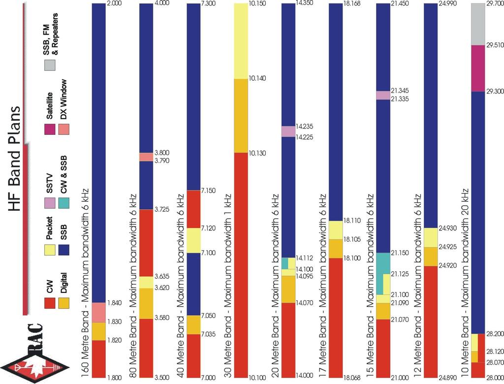
5 What Does HF Mean? HF stands for HIGH FREQUENCY These are the frequencies from 1.8* to 30 MHz or the 160 meter to 10 meter bands. HF is also known as shortwave. *160m is actually a Medium Frequency (MF) band but it is included in the Amateur HF bands for ease of discussion.
6 How is HF different than FM repeaters? No machine (repeater) or infrastructure is used.
7 How is HF different than FM repeaters? Allows communication beyond line of sight. Contacts are generally a couple of hundred miles to over several thousand miles.
8 How is HF different than FM repeaters? Propagation is strongly affected by solar activity.
9 How is HF different than FM repeaters? Several communication modes are available to use. SSB, CW, RTTY, SSTV, Digital, AM
10 HF Band Allocation Basic with 80% is the minimum requirement Meter Band From Industry Canada RBR-4 Frequency range Allowed Bandwidth License Class khz B-80% khz B-80% khz B-80% khz B-80% khz B-80% khz B-80% khz B-80% khz B-80% khz B-80%
11
12 Who Uses HF? Because of the ability to communicate over long distances, HF is used by many government, military, and commercial agencies worldwide.
13 Who Uses HF? Amateur Radio operators all over the world use HF for the same reasons of being able to communicate over long distances.
14 Amateur Radio & HF When most people hear the term ham radio they generally think of HF or shortwave and long distance communications.
15 Who Has HF Privileges? In Canada, the following Amateur Radio Operators have HF privileges: Basic with a mark of 80% or more. Operator certificate with 5 wpm code. Advanced Operator certificate.
16 HF is FUN With a 100 watt transceiver and a simple wire antenna you can start to communicate and make friends with other hams all over the country or the world.


17 HF is FUN What this program covers

18 HF is FUN 1. We will talk about how and why radio waves can travel great distances around the world.

19 HF is FUN 2. We will talk about HF radios and some of their features.

20 HF is FUN 3. We will explain to you what some of the controls are on the radio and what it is that they do.

21 HF is FUN We will talk about simple antennas that are: very effective, Inexpensive and easy to construct and install.
22 HF is FUN 5. We will also talk about some of the ways that amateurs configure their antennas to affect where their signals are going to go.
23 HF is FUN Let s Get Started

24 Hearing Signals Out of Thin Air
25 How It Works (Propagation) Just as sailors use the natural forces and currents of wind and water to guide their boats,
26 How It Works (Propagation) radio operators use naturally occurring charges in a layer of the atmosphere called the ionosphere to bend and reflect their radio signals.

27 Why It Works (The Atmosphere) The Earth s atmosphere is made up of several layers or regions.
28 Why It Works (The Atmosphere) We are most concerned with the uppermost region called the ionosphere. *The ionosphere is part of the thermosphere and not a separate layer or region. For our discussion we will only refer to the layers that make up the ionosphere.

29 The Role of Sol How the Sun Opens and Closes The Bands
30 The Sun s energy causes atoms in the upper atmosphere to become charged. These charged particles are called ions.
31 This charged region of the upper atmosphere is called the ionosphere.
32 When a radio wave enters this region of charged particles, its direction of travel is altered.
33 Radio waves change direction when they enter the ionosphere
34 The Ionosphere The ionosphere is broken up into layers. These layers are the D, E and F layers.* *There is no A, B, or C layer. These were reserved for possible future discoveries.
35 The Ionosphere The Sun s UV radiation charges these layers and this affects radio waves and how they travel.
36 The Layers of the Ionosphere
37 The D Layer The D Layer is the lowest and densest region of the ionosphere. It extends 37 to 57 miles (59 to 91 Km) above the Earth s surface.
38 The D Layer Because of its density, the D-layer tends to absorb radio signals.
39 The D Layer The absorption of RF varies by wavelength. Longer waves such as 160m and 80m are most affected.
40 The D Layer D-layer effect is less on 40m, slight on 20m and inconsequential on the higher frequencies.
41 The D Layer The ionization level of this lower part of the atmosphere is directly related to the sunlight.
42 The D Layer Therefore, The D-layer begins at sunrise, peaks at noon and disappears at sunset.
43 The D Layer The Sun s ionization of the upper atmosphere and creation of the D layer is what closes the low bands during the day.
44 The D Layer The disappearance of the D layer at sunset opens the low bands and they will remain open throughout the night.
45 The E Layer At 62 to 71 miles (99 to 114 Km) above the Earth, the E layer is the lowest portion of the ionosphere useful for long distance communications.
46 The E Layer Ionization of the E layer occurs rapidly after sunrise and diminishes quickly after sunset. Minimum ionization of the E layer is after midnight, local time.
47 The E Layer Like the D-layer, the E-layer absorbs long wavelength signals during the day.
48 The E Layer Signal absorption is highest when the sun is at it s highest angle. (local noon)
49 The E Layer The E layer effects other Amateur bands above 30 MHz but for now we will limit our discussion to the HF bands.
50 The F Layer The F layer is the uppermost region of the atmosphere. It begins at approximately 100 miles (160 Km) and can extend to over 310 miles (496 Km) above the Earth s surface.
51 The F Layer The F layer is responsible for most of our long distance communications.
52 The F Layer Because this region is so far away from the Earth s surface it is less dense than the other regions.
53 The F Layer It often takes a while for noticeable effects of the Sun s radiation to develop but the charges can last long after sunset.
54 The F Layer During the day in summertime the Sun s radiation can cause the F layer to become two separate layers called F-1 and F-2 layers. The lower F-1 layer doesn t last long after sunset.
55 The F Layer The effects of the Sun on the ionosphere change as the seasons change because the angle between the Sun and the Earth changes throughout the yearly cycle.
56 The F Layer In the summer, during periods of high solar activity, it is not unusual to see bands like 10 and 15 meters stay open until midnight and 20 meters stay open all night.
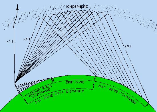
57 Skipping Signals In order to travel distances greater than line of sight, radio signals skip off the ionosphere and return to Earth.
58 Radio waves encountering the ionosphere above the critical angle don t get bent enough to return to Earth. Waves entering at angles below the critical angle reach the Earth at increasingly greater distances as the launch angle approaches horizontal.

59 Higher frequencies at or near the maximum usable frequency (MUF)

60 Lower frequencies at or below the critical frequency are refracted more vertically
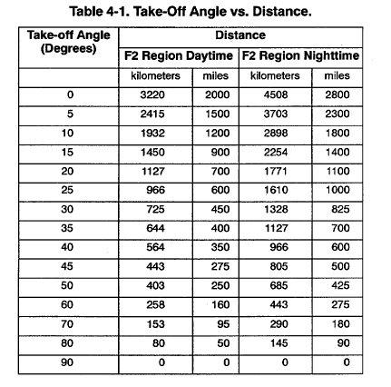
61 Skipping Signals Like skipping a stone on a pond, if we send our signals off at very low angles they will make more hops and travel farther.
62 Skipping Signals HF operators will configure their antennas so that they can direct their signals where they want them.
63 Skipping Signals HF operators also know what frequency to use at different times of the day or season for effective communications.
64 Propagation There are three basic types of propagation of HF radio signals: 1.Sky-wave 2.Ground wave 3.High Angle Radiation (NVIS)
65 Propagation
66 Sky-Wave The Sky-wave is the wave that travels to the upper regions of the atmosphere and gets reflected back to Earth by the ionized layers that we previously learned about.
67 Sky-Wave The Sky-wave is the wave that is responsible for all of our long distance communications.
68 Sky-Wave For long distance (DX) communications, Amateurs configure their antennas so that the radio waves take off at very low angles (20 degrees or less above the horizon)
69
70 Ground Wave Ground wave is the signal that radiates (propagates) close to the ground, between the Earth s surface up and the lower atmosphere or troposphere and can be reflected or diffracted by the terrain. Unlike VHF which is limited to line-of-sight (direct wave), the ground wave can extend over the horizon.
 on HF during the day, but do extend beyond the")
71 Ground Wave Ground waves are generally good for less than 100 miles (160 Km) on HF during the day, but do extend beyond the horizon.
72 High Angle Radiation NVIS or Near Vertical Incidence Sky-wave
73 NVIS Radio Waves that take off at very high angles are reflected straight back down to Earth.
74 NVIS Like squirting a hose at the ceiling, this technique allows you to blanket your signals over a significant area close to your station.
75 NVIS concept
76 NVIS This technique will provide reliable communications within a 200 to 350 mile (320 to 560 Km) radius. Frequency choice for NVIS is typically 40m during the day and 80m at night Unlike the ground wave, NVIS signals are not affected by terrain.
77 The Gray Line The transition between daylight and darkness is called the gray line. This area offers some unique and special propagation to the radio operator. The D layer, which absorbs HF signals, disappears rapidly on the sunset side of the grey line, and it has not yet built up on the sunrise side. Works predominately north-south.
78 The gray line or terminator is a transition region between daylight and darkness. One side of the Earth is coming into sunrise, and the other is just past sunset.

79 Building a Station Building an effective HF station is very simple.
80 Building a Station There are basically two main components involved: 1. A 100 watt Transceiver and 2. An antenna system. The antenna system consist of the radiator, feedline and matching network.
81 Building a Station Accessories As you become more involved in HF activity you will find that there are certain accessories that will make building and operating your station a little easier.
82 Transceivers What is a Transceiver? A transceiver is a single unit that acts as transmitter and receiver.
83 Transceivers There are many transceivers on the market today. For our discussion will limit ourselves to the 100 watt, all mode class of transceivers.
84 Transceivers All of the current commercially manufactured transceivers on the market today are state of the art and can provide good communications worldwide
85 Transceivers some of the better units offer more sophisticated circuits designed to increase the receiver s ability to hear weak signals.
86 Transceivers You do get what you pay for. Commercial manufacturers tend offer units in a good, better, best category.
87 Transceivers There are a lot of good values to be had in the used equipment market. It is a good idea to consult an experienced operator before you buy a used piece of gear.
88 Transceivers Whichever transceiver you choose, you can be assured of many years of operating pleasure from your investment.
89 A Word About Classic Radios. You will often hear hams talk about old classics and rigs that they used back in the day.

90 A Word About Classic Radios. Classic radios are like classic cars.

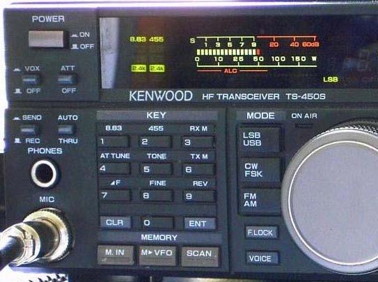
91 A Word About Classic Radios. They re nice to look at and fun to tinker with. Kenwood TS-820S Uses 3 tubes, 38 IC s, 126 transistors, and 195 diodes. Weighs 37 lbs (without power supply).

92 A Word About Classic Radios. It s a thrill take them out for a spin and show them off once in a while. Heathkit HW-101 Uses 20 tubes, 16 diodes, 2 transistors and weighs 18 lbs without power supply. Power supply weighs approx. 20lbs.
93 A Word About Classic Radios. However, for your daily use you want to have something that is modern and reliable. Many old transceivers use one or more tubes.
94 A Word About Classic Radios. Unless you are very talented and have a source for extinct components it is a good idea to avoid these boat anchors as a first or primary radio.
95 Transceivers What makes a good radio? Scanning, memories and other bells & whistles are not the important features that make a good HF rig.
96 Transceivers What makes a good radio? The receiver s ability to hear weak signals and separate the incoming signals are what makes a good HF rig.
97 Transceivers What makes a good radio? The numbers to look at when selecting a transceiver are: sensitivity (ability to hear signals) and selectivity (ability to distinguish signals)

98 Transceivers What makes a good radio? Remember, you can t work them if you can t hear them.


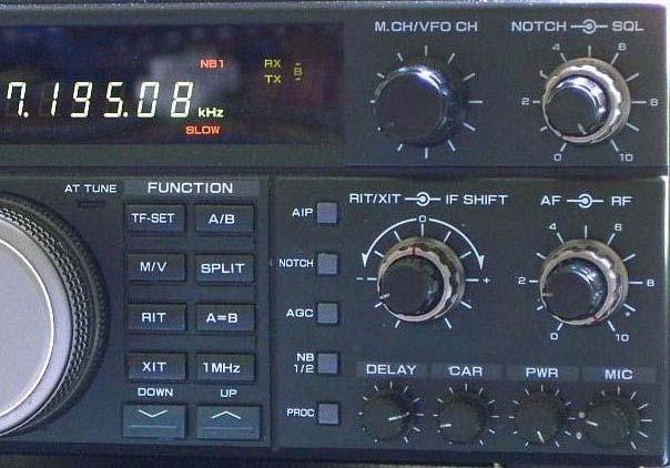
99 Transceivers Common Controls Found On Amateur Radio Transceivers.


100 Multi function meter shows information at a glance Use the meter like the speedometer in your car; don t stare at it, but glance at it, making sure all things are proper.
101 Meter Functions S or Signal strength This indicates the relative strength of a received signal on a scale of 1 through 9 (a 1 S-unit change is about a 6 db change). Strong signals are reported as db over S9. 10 over over, etc. (a change of 6dB is a 4 times change)


102 Reading The S Meter The receive signal on the meter on the left is almost 50 db over S-9 or simply said, 50 over. The one on the right is 30 over and the bottom is 20 over.

103 Meter Functions RF POWER This shows how much power the transmitter is putting out. MAX is good.
104 Meter Functions SWR This shows the Standing Wave Ratio of the antenna or how much power is being reflected back to the radio. A 1:1 (perfect) is excellent, 1.5:1 is good, 2:1 is fair.
105 Meter Functions ALC This shows the condition of the Automatic Limiting Control circuitry. You want to make sure that you are not overdriving your transmitter. A good reading is when the peaks top the scale and stay within the range marked on the meter scale.

106 Meter Functions Below the frequency readout are scales for: S-Meter, Power Output, ALC, Voice Compression, and SWR.

107 What Are All Those Knobs?

108 VFO Variable Frequency Oscillator. This is the main tuning knob used to tune in a station. This tunes your transmit and receive frequency that is shown on the MAIN DISPLAY.

109 AF (gain) Audio Frequency gain. This is the VOLUME control for the receiver.
110 Controls RF GAIN This allows you to adjust the gain of the receiver amplifier circuits. It allows you to make the circuits less sensitive so that you can dampen really strong signals. Normally left fully clockwise maximum.
111 Controls By changing the gain in the receiver circuits you can lower the noise floor and effectively improve the signal to noise ratio, thus improving your ability to hear weaker signals.
112 Controls When you adjust the RF GAIN it is normal to see the S METER rise (it will no longer read correctly).
113 Controls AGC Normally left ON (don t use MANUAL AGC). AGC reduces RX gain with strong signals but after a short delay will allow gain to increase to hear weak signals. The speed (SLOW, MEDIUM or FAST) determines how long the gain takes to recover. Use FAST or MEDIUM for SSB (set the AGC speed so as to minimize pumping of the background noise from the RX).
114 Controls MIC GAIN- This controls the loudness of the microphone in any voice mode. It is best to adjust this for a good in range reading on the ALC meter.
115 Controls Voice Processor or Voice Compressor Used to help maintain a relatively constant (high) transmit power output with varying loudness levels of your voice. In SSB, TX power is zero during pauses in your speech when no sound enters the microphone, and 100% on the loudest voice peaks when you talk. The processor can help keep the average power closer to maximum. Adjust so that the ALC meter only moves a small amount, too much processing causes distortion.
116 Controls MODE This allows you to choose the mode of operation for your transceiver. CW Continuous Wave (Morse code) USB Upper Sideband LSB Lower Sideband RTTY Radio Teletype
117 Controls SSB Operation USB is normally used on the 5 bands from 10M through 20M. LSB is normally used on 40M through 160M. Voice communications are not permitted on the 30M band (1KHz bandwidth limit).
118 Controls RIT This stands for Receive Incremental Tuning and is used to fine tune a station you are listening to without changing your transmit frequency. This is sometimes called a Clarifier.
119 Controls XIT- Transmit Incremental Tuning is similar to RIT but it adjusts your transmit frequency.
120 Controls RF PWR This adjusts the amount of transmitter output power. The power meter can indicate actual watts or the percent (of the maximum output the transceiver is capable of)
121 Controls IF SHIFT - This shifts the center of the receiver s pass band to help reduce interference from a nearby signal. Pronounced eye eff, it stands for Intermediate Frequency
122 Controls Shifting the IF allows you to avoid a signal that is close to yours by not letting it in the window of the receiver s pass band.
123 Controls NOTCH This is another good filter for reducing nearby interference. Unlike a window, it acts like a cover and blocks the signal that is in your window.
124 Controls A transceiver can have both manual notch filters that you can adjust to reduce a hetrodyne for example, and/or automatic notch filters which will automatically center on the offending hetrodyne so that you do not hear it, but can still hear the desired signal.
125
126
127 Antennas
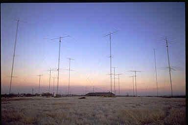
128 Antennas Now calm down. You don t need an antenna farm like the one shown at N5AU to have fun on HF.
129 Antennas When we talk about our antennas we are actually talking about an antenna system.
130 BIG NOTE * *An entire program can be had just on the discussion of antennas. Consideration should be given to safety and the type of operating that is being done, as well as spouse appeal. End of Big Note.
131 Antennas An antenna system consists of: 1. The antenna or radiator 2. The feedline 3. The matching network or tuner
132 SWR A good SWR is not an indicator of an effective antenna system. Click your heels and say this three times.
133 SWR Think of a dummy load; it has a very good SWR but it is not an effective antenna.
134

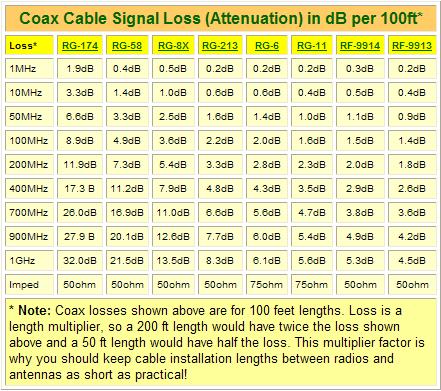
135 How feedline loss affects the VSWR indicated at the transmitter it s worse than you think!
136 Antennas The dipole is the simplest antenna that any amateur can use on HF. Whether fed with coax or open wire, dipoles are cheap and easy to build and install.
137 Antennas A dipole fed with twin lead can be made to operate effectively on more than one band when using a good matching network.
138 Antennas A dipole can be made for a single band. The total length of the antenna can be calculated by using the formula: 468 freq (MHz) = length in feet
139 Antennas Each side, or leg, of the dipole is going to be one half of the total length. Fed with 50 ohm coax, this antenna will be resonant on a single band that it was cut for.
140 468 f (MHz) Feedline The Dipole Radiator, Feedline and matching network matching network
141
142
143 Antennas It is not necessary to install dipoles in a horizontal straight line.
144 Antennas Configurations include bent, drooping, inverted V and sloper.
145
146 Inverted V
147
148 Sloper
149 Antennas The tri-band Yagi or beam antenna is popular among a lot of HF operators. Even a modest 3 element model at heights as low as 40 ft can greatly improve your signal.
150 Antennas Many hams have earned their DXCC award using a small triband beam and 100 watts of power.
151 Three Element Tri-band Yagi
152 Antennas Vertical Antennas It is recommended that you read about vertical antennas in the ARRL Antenna Book before installing one.
153 Antennas Many hams new to HF can become disappointed by vertical antennas because they don t understand how they work or listen to myths about them.

154 Vertical antennas are excellent low angle radiators (good for DX) Ground mounted verticals require an extensive radial system. Elevated mono-band verticals only require 4 radials to be effective. Some multiband verticals such as the Cushcraft R7 & R8 must be mounted at least 15 feet off the ground to work properly.
155 Antennas Vertical antennas are excellent low angle radiators and are great for DXing. A lot of big gun stations have verticals in their arsenal of antennas.
156 Antennas Large antenna arrays are extremely effective. The down side is that they require a lot of space, they re expensive and they require periodic maintenance and safety inspections.

157 Antennas W1AW One of the towers at ARRL Headquarters. This 120 foot tower stands well above the local tree line and has lots of aluminum on it.
158 Antennas As you become a more experienced operator you will modify and improve your antenna farm. The most important thing now is to get a wire up and start having some fun.
159 Antenna Patterns The Vertical

160 Antenna Patterns Horizontal Dipole
161 G5RV Multiband Dipole Mounted 65 Feet Above Ground Viewed from above - antenna orientation is horizontally through these antenna patterns


162 Antenna Pattern for a 3 Element Yagi


163 Matching Networks The terms antenna tuner, match box, Transmatch and antenna coupler, are all synonyms for a matching network.
164 Matching Networks A matching network is a combination of inductance and capacitance used to cancel out unwanted reactance to better couple the transmitter power to the antenna.
165 Matching Networks Most modern transceivers have built in antenna tuners or matching networks that will match the transmitter section to the antenna and feedline. Most radio equipment expects a 50 ohm load (antenna).
166 Matching Networks Think of the matching network like the transmission in a car.
167 Matching Networks While it is possible to connect the drive wheel directly to the engine, you will achieve a much more efficient transfer of power by using a transmission.
168 Matching Networks The matching network provides an efficient transfer of power from the transceiver to the antenna.
169 Matching Networks However, the use of a matching network to achieve low SWR does not make a poor antenna radiate better.
170 Matching Networks The most common matching networks are the T- network, the Pi-network and the L-network. A manual tuner would use one of these circuits. The knobs on the front are for changing the inductance and capacitance.
171 L-Network
172 Pi-Network
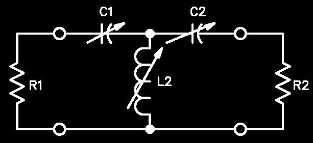
173 T-Network


174 Antenna Matching VSWR Power reflected 1.0 : 1 0% 1.3 : 1 2% 1.6 : 1 5% 2.0 : 1 10% 3.0 : 1 25% 6.0 : 1 50%

 Ladder Line (e.g.")
175 Feedline The line that connects the antenna to the radio is called the feedline. Coax Cable (e.g. 50ohm RG-8) Ladder Line (e.g. 300 or 450 ohm)
176 Feedline For the purpose of this demonstration we will only mention 50 ohm coax (unbalanced) and balanced ladderline or twin lead.
177 Feedline Most hams use 50 ohm coax to feed their antennas. It is easy to use and requires no special handling to bring it into the shack.
178 Feedline Because of the 50 ohm impedance of the coax it matches the output of all modern transceivers.
179 Feedline In addition to matching the transceiver output, the 50 ohm coax also closely matches the feedpoint impedance of a resonant dipole.
180 Feedline Twin lead or ladderline is used on mono- or multi-band antennas. Because it is balanced, it has no feedline losses.
181 Feedline When used with a good tuner, a dipole fed with ladderline can be a very effective all band antenna system.
182 Safety Electrical Safety RF Safety Physical Safety
183 Grounding For safety and to prevent interference, your station should be well grounded.
184 Grounding A good general statement is to have an earth ground using an 8 foot ground rod as close to the equipment as possible.
185 Grounding Avoid grounding to water pipes and such. NEVER connect a ground to a gas pipe.
186 Grounding All equipment should be grounded to a common point and then connected to the ground rod. DO NOT daisy chain or ground equipment to each other.
187
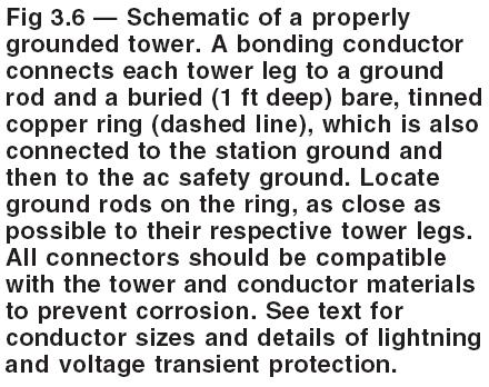
188 Grounding All antennas and antenna support structures (masts and towers) must be grounded.
189
190 Grounding All ground leads should be as short as possible and made with heavy gauge wire or wide copper strap.
191 Grounding Please refer to the ARRL handbook for additional information on station grounding.
192 RF Safety As a licensed Amateur Radio operator you are required to know about RF exposure.
193 RF Safety Most 100 watt stations will not have any difficulty in meeting FCC/IC exposure requirements.
194 RF Safety However, it is your responsibility to verify proper installation and operation of your station equipment and antennas.
195 RF Safety Complete information about RF safety can be found on the ARRL website Or in the ARRL publication RF Exposure and You by Ed Hare, W1RFI
196 Physical Safety NEVER attempt to erect antennas near powerlines. You will be killed.
197 Physical Safety Always use safety equipment when climbing towers or roofs. Keep all ladders on solid surfaces.
198 Physical Safety Don t work alone. It is a good idea to have a helper when trying to hang wires or climb towers.
199 Get On The Air Experienced HF operators in your local club will be able to advise you as you build your station.
200 Get On The Air DX and contesting clubs are good sources of information for HF operating. DX spotting websites tell you what stations other hams are hearing. One is DX-Summit:
201 Get On The Air Contests & Operating Events Participation in operating events will improve your skills and enhance your operating pleasure. Answering a few CQ s from contesters is a good way to collect a few QSL cards. Contest Calendar:
202 Get On The Air These events also provide opportunities to find ways to improve your station.
203 Get On The Air Awards There are many awards available for the HF operator to earn. Canadian Awards Listing: DX Awards and Certificates:
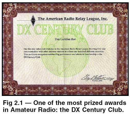
204 Get On The Air Awards The most coveted is the DX Century Club or DXCC, awarded for making contact with 100 countries.
205
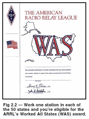
206 Get On The Air Awards There are many other awards including the Worked All States (WAS) award for contacts with all 50 U.S States.
207
208 Get On The Air Choosing the band or mode of operation is up to you. Listen for activity on all the bands; 40m 10m during the day, 160m, 80m & 40m at night.
209 Get On The Air Now that you have the basics of HF operating, it s time to get on the air and start having fun.

210 Publications: RAC License Manuals


211 Morse Code Study Materials

212 Publications ARRL Handbook

213 Publications ARRL Antenna Book

214 Publications ON4UN's Low-Band DXing Antennas, Equipment and Techniques for DXcitement on 160, 80 and 40m

215 Publications The Complete DX'er by Bob Locher, W9KNI

216 Publications On the Air with Ham Radio By Steve Ford, WB8IMY

217 Publications QRP Communications QRP means operating with low power 5 watts or less. QRPp means operating with 1 watt or less.

218 Publications RF Exposure and You By Ed Hare, W1RFI

219 Contact Norm Fusaro, W3IZ ARRL Affiliated Clubs/Mentor Program Manager 225 Main St. Newington, CT Presentation modified for use in Canada by Al Duncan VE3RRD Barrie Amateur Radio Club (rev 2 Jan 2010)
Discover the Magic Of. HF Radio
 Discover the Magic Of HF Radio Welcome to Worldwide Communications This presentation is designed to introduce the new or recently upgraded ham to HF radio. Welcome to Worldwide Communications The information
Discover the Magic Of HF Radio. By Norm Fusaro, W3IZ
 Discover the Magic Of HF Radio By Norm Fusaro, W3IZ HF is FUN With a 100 watt transceiver and a simple wire antenna you can start to communicate and make friends with other hams all over the country or
Elmer Session Hand Out for 3/3/11 de W6WTI. Some Common Controls Found On Amateur Radio Transceivers. (From ARRL web site tutorial)
") Elmer Session Hand Out for 3/3/11 de W6WTI Some Common Controls Found On Amateur Radio Transceivers. (From ARRL web site tutorial) The placement of the controls may vary from manufacturer to manufacturer
Elmer Session Hand Out for 3/3/11 de W6WTI Some Common Controls Found On Amateur Radio Transceivers. (From ARRL web site tutorial) The placement of the controls may vary from manufacturer to manufacturer
The Fabulous Dipole. Ham Radio s Most Versatile Antenna
 The Fabulous Dipole Ham Radio s Most Versatile Antenna 1 What is a Dipole? Gets its name from its two halves One leg on each side of center Each leg is the same length It s a balanced antenna The voltages
Antennas and Propagation Chapters T4, G7, G8 Antenna Fundamentals, More Antenna Types, Feed lines and Measurements, Propagation
 Antennas and Propagation Chapters T4, G7, G8 Antenna Fundamentals, More Antenna Types, Feed lines and Measurements, Propagation =============================================================== Antenna Fundamentals
Introduction to HF Propagation. Rick Fletcher, W7YP FVARC November 20, 2018
 Introduction to HF Propagation Rick Fletcher, W7YP FVARC November 20, 2018 Topics The HF Bands How HF propagation works Overview by HF band Sources of solar and propagation information Working HF during
Technician License Course Chapter 4
 Technician License Course Chapter 4 Propagation, Basic Antennas, Feed lines & SWR K0NK 26 Jan 18 The Antenna System Antenna: Facilitates the sending of your signal to some distant station. Feed line: Connects
Chapter 7 HF Propagation. Ionosphere Solar Effects Scatter and NVIS
 Chapter 7 HF Propagation Ionosphere Solar Effects Scatter and NVIS Ionosphere and Layers Radio Waves Bent by the Ionosphere Daily variation of Ionosphere Layers Ionospheric Reflection Conduction by electrons
Lesson 12: Signal Propagation
 Lesson 12: Signal Propagation Preparation for Amateur Radio Technician Class Exam Topics HF Propagation Ground-wave Sky-wave Ionospheric regions VHF/UHF Propagation Line-of-sight Tropospheric Bending and
FCC Technician License Course
 FCC Technician License Course 2014-2018 FCC Element 2 Technician Class Question Pool Presented by: Tamiami Amateur Radio Club (TARC) WELCOME To the third of 4, 3-hour classes presented by TARC to prepare
Amateur Radio License. Propagation and Antennas
 Amateur Radio License Propagation and Antennas Todays Topics Propagation Antennas Propagation Modes Ground wave Low HF and below, ground acts as waveguide Line-of-Sight (LOS) VHF and above, radio waves
Chapter 6 Antenna Basics. Dipoles, Ground-planes, and Wires Directional Antennas Feed Lines
 Chapter 6 Antenna Basics Dipoles, Ground-planes, and Wires Directional Antennas Feed Lines Some General Rules Bigger is better. (Most of the time) Higher is better. (Most of the time) Lower SWR is better.
ANTENNA THEORY WAVE PROPAGATION HF ANTENNAS
 ANTENNA THEORY WAVE PROPAGATION & HF ANTENNAS FREQUENCY SPECTRUM INFORMATION Frequency range American designator below 300 Hz..ELF (extremely Low Frequency) 300-3000 Hz..ILF (Intermediate Low Frequency)
Emergency Antennas VHF / UHF - FM. HF Voice, CW, or Digital
 1 Emergency Antennas VHF / UHF - FM HF Voice, CW, or Digital 2 Antennas for VHF Quarter Wave Vertical Half Wave Vertical Vertical Dipole J-Pole 3 Design Parameters Primarily line of sight Mounted on trunk
Technician License Course Chapter 4. Lesson Plan Module 9 Antenna Fundamentals, Feed Lines & SWR
 Technician License Course Chapter 4 Lesson Plan Module 9 Antenna Fundamentals, Feed Lines & SWR The Antenna System Antenna: Transforms current into radio waves (transmit) and vice versa (receive). Feed
Technician Licensing Class. Antennas
 Technician Licensing Class Antennas Antennas A simple dipole mounted so the conductor is parallel to the Earth's surface is a horizontally polarized antenna. T9A3 Polarization is referenced to the Earth
Technician Licensing Class. Lesson 4. presented by the Arlington Radio Public Service Club Arlington County, Virginia
 Technician Licensing Class Lesson 4 presented by the Arlington Radio Public Service Club Arlington County, Virginia 1 Quiz Sub elements T6 & T7 2 Good Engineering Practice Sub element T8 3 A Basic Station
4/29/2012. General Class Element 3 Course Presentation. Ant Antennas as. Subelement G9. 4 Exam Questions, 4 Groups
 General Class Element 3 Course Presentation ti ELEMENT 3 SUB ELEMENTS General Licensing Class Subelement G9 Antennas and Feedlines 4 Exam Questions, 4 Groups G1 Commission s Rules G2 Operating Procedures
1) Transmission Line Transformer a. First appeared on the scene in 1944 in a paper by George Guanella as a transmission line transformer, the 1:1
 Transmission Line Transformer a. First appeared on the scene in 1944 in a paper by George Guanella as a transmission line transformer, the 1:1") 1) Transmission Line Transformer a. First appeared on the scene in 1944 in a paper by George Guanella as a transmission line transformer, the 1:1 Guanella Balun is the basic building Balun building block.
1) Transmission Line Transformer a. First appeared on the scene in 1944 in a paper by George Guanella as a transmission line transformer, the 1:1 Guanella Balun is the basic building Balun building block.
General License Class Chapter 6 - Antennas. Bob KA9BHD Eric K9VIC
 General License Class Chapter 6 - Antennas Bob KA9BHD Eric K9VIC Learning Objectives Teach you enough to get all the antenna questions right during the VE Session Learn a few things from you about antennas
Beams and Directional Antennas
 Beams and Directional Antennas The Horizontal Dipole Our discussion in this chapter is about the more conventional horizontal dipole and the simplified theory behind dipole based designs. For clarity,
Welcome to Ham Radio 201 New General / Extra Session
 Welcome to Ham Radio 201 New General / Extra Session Sponsored by Agenda New Technician / New Licensee 8:00 Kickoff 8:15 VHF/UHF Gear - George 9:00 VHF/UHF Operating - Beric 9:45 VHF Digital Voice George
Newcomers And Elmers Net: Wire Antennas Robert AK3Q
 Newcomers And Elmers Net: Wire Antennas 02-07-16 Robert AK3Q Wire antennas represent one of the greatest values in the radio hobby world. For less than the cost of a good meal out on the town you can buy
Technician Licensing Class T9
 Technician Licensing Class T9 Amateur Radio Course Monroe EMS Building Monroe, Utah January 11/18, 2014 January 22, 2014 Testing Session Valid dates: July 1, 2010 June 30, 2014 Amateur Radio Technician
4/29/2012. General Class Element 3 Course Presentation. Radio Wave Propagation. Radio Wave Propagation. Radio Wave Propagation.
 General Class Element 3 Course Presentation ti ELEMENT 3 SUB ELEMENTS General Licensing Class Subelement G3 3 Exam Questions, 3 Groups G1 Commission s Rules G2 Operating Procedures G3 G4 Amateur Radio
VHF/UHF Beyond FM Bob Witte KØNR Page 1
 VHF/UHF Beyond FM Technical Coordinator Colorado Section Page 1 Objective The objective of this presentation is to provide an introduction to operating on VHF/UHF, going beyond the usual FM / Repeater
Lesson 9: Base Stations
 Lesson 9: Base Stations Preparation for Amateur Radio Technician Class Exam Topics Home Stations Basic Station Layout RTTY and Data Communications Station Accessories Wavelengths Feed Lines Impedance-matching
right during the VE Session Have fun Bob, KA9BH Eric, K9VIC
 Radio Wave Propagation Teach you enough to get all right during the VE Session Learn a few things from you Have fun Finish everything on time (if the propagation questions about your experiences not a
Reading 28 PROPAGATION THE IONOSPHERE
 Reading 28 Ron Bertrand VK2DQ http://www.radioelectronicschool.com PROPAGATION THE IONOSPHERE The ionosphere is a region of the upper atmosphere extending from a height of about 60 km to greater than 500
General Class License Theory III. Dick Grote K6PBF
 General Class License Theory III Dick Grote K6PBF K6pbfdick@gmail.com 1 Introduction In this session we will learn about: Feed Lines Antennas Safety As in the other theory classes, we will try to present
Technician License Course Chapter 2 Radio and Electronics Fundamentals. PHYS 401 Spring 2009 P. Reiff, Rice University
 Technician License Course Chapter 2 Radio and Electronics Fundamentals PHYS 401 Spring 2009 P. Reiff, Rice University Basic Station Organization Station Equipment Receiver Transmitter Antenna Power Supply
4/25/2012. Supplement T9. 2 Exam Questions, 2 Groups. Amateur Radio Technician Class T9A: T9A: T9A: T9A:
 Amateur Radio Technician Class Element 2 Course Presentation ti ELEMENT 2 SUB-ELEMENTS Technician Licensing Class Supplement T9 Antennas, Feedlines 2 Exam Questions, 2 Groups T1 - FCC Rules, descriptions
DO NOT COPY. Basic HF Antennas. Bill Shanney, W6QR
 Basic HF Antennas Bill Shanney, W6QR When I was first licensed in 1961 I didn t know much about antennas. I put up the longest wire that fit on my parent s lot at the lofty height of 25 and fed it with
NVIS, Another Look. Tom Sanders, W6QJI Ed Bruette, N7NVP
 NVIS, Another Look Tom Sanders, W6QJI Ed Bruette, N7NVP Regional Communications N.V.I.S. Near Vertical Incidence Skywave What is NVIS? Near Vertical Incident Skywave Cloud Warmer Propagation Theory NVIS
Optimizing Your Stations Performance
 Optimizing Your Stations Performance A few hints / techniques, recommendations for getting the most RF out to the Antenna from your HF, VHF / UHF station. Tonights Presenters: Doug Theriault NO1D John
Results for sample general2015 test paper
 1 / 8 2016/09/22 15:51 Your answers are marked like this: A. You got this question right, this is your correct answer. A. You got this question wrong, this is your incorrect answer. A. You got this question
Technician License. Course
 Technician License Course Technician License Course Chapter 4 Lesson Plan Module - 10 Practical Antennas The Dipole Most basic antenna The Dipole Most basic antenna The Dipole Total length is ½ wavelength
Antenna Design for FM-02
 Antenna Design for FM-02 I recently received my FM-02 FM transmitter which I purchased from WLC. I researched the forum on what antennas where being used by the DIY community and found a nice write-up
Last year I described several Low Band RX antennas that would enable you to hear DX stations on 160, 80 and 40M. This will show you how to build
 Last year I described several Low Band RX antennas that would enable you to hear DX stations on 160, 80 and 40M. This will show you how to build transmit antennas that will help you break the pileups!
Least understood topics by most HAMs RF Safety Ground Antennas Matching & Feed Lines
 Least understood topics by most HAMs RF Safety Ground Antennas Matching & Feed Lines Remember this question from the General License Exam? G0A03 (D) How can you determine that your station complies with
Newspaper cartoon from the early 60 s
 Newspaper cartoon from the early 60 s NVIS for Emergency Communications Ross Mazzola Monroe County (NY) ARES Why NVIS? Damage to Infrastructure Inoperative Towers & Repeater Sites Loss of Backup Power
High Frequency Propagation (and a little about NVIS)
") High Frequency Propagation (and a little about NVIS) Tom McDermott, N5EG August 18, 2010 September 2, 2010 Updated: February 7, 2013 The problem Radio waves, like light waves, travel in ~straight lines.
High Frequency Propagation (and a little about NVIS) Tom McDermott, N5EG August 18, 2010 September 2, 2010 Updated: February 7, 2013 The problem Radio waves, like light waves, travel in ~straight lines.
Definitions of Technical Terms
 Definitions of Technical Terms Terms Ammeter Amperes, Amps Band Capacitor Carrier Squelch Diode Dipole Definitions How is an ammeter usually connected = In series with the circuit What instrument is used
Space Weather and Propagation JANUARY 14, 2017
 Space Weather and Propagation MARTIN BUEHRING -KB4MG ELEC T R ICAL ENGINEER, A M AT EUR EXTRA CLASS LICENSE HOLDER JANUARY 14, 2017 Why know about Space Weather? Our SUN has an enormous affect not only
One I had narrowed the options down, I installed some wire and started testing.
 Loft & Attic antennas for restricted spaces - M. Ehrenfried G8JNJ I ve recently been looking at designs for an efficient antenna that would fit in a loft. I hoped to find something that would work on with
Cray Valley Radio Society. Real Life Wire Antennas
 Cray Valley Radio Society Real Life Wire Antennas 1 The basic dipole The size of an antenna is determined by the wavelength of operation In free space: ~3x10 8 m/s Frequency x Wavelength = Speed of Light,
ANTENNAS. I will mostly be talking about transmission. Keep in mind though, whatever is said about transmission is true of reception.
 Reading 37 Ron Bertrand VK2DQ http://www.radioelectronicschool.com ANTENNAS The purpose of an antenna is to receive and/or transmit electromagnetic radiation. When the antenna is not connected directly
ADJUSTING YOUR HF RECEIVER
 ADJUSTING YOUR HF RECEIVER N5KIP January 31, 2017 Disclaimers What works on one model of radio might not work well on another CW (narrow bandwidth) and SSB (wider bandwidth) will require different receiver
Maximum Usable Frequency
 Maximum Usable Frequency 15 Frequency (MHz) 10 5 0 Maximum Usable Frequency Usable Frequency Window Lowest Usable Frequency Solar Flare 6 12 18 24 Time (Hours) Radio Blackout Usable Frequency Window Ken
Antennas Demystified Antennas in Emergency Communications. Scott Honaker N7SS
 Antennas Demystified Antennas in Emergency Communications Scott Honaker N7SS Importance of Antennas Antennas are more important than the radio A $5000 TV with rabbit ears will have a lousy picture Antennas
Ham Radio Training. Level 1 Technician Level. Presented by Richard Bosch KJ4WBB
 Ham Radio Training Level 1 Technician Level Presented by Richard Bosch KJ4WBB In this chapter, you ll learn about: What is a radio signal The characteristics of radio signals How modulation adds information
Results for sample general2015 test paper
 1 / 7 2016/09/21 15:14 Results for sample general2015 test paper Your answers are marked like this: A. You got this question right, this is your correct answer. A. You got this question wrong, this is
Technician License Course Chapter 5. Lesson Plan Module 11 Transmitters, Receivers and Transceivers
 Technician License Course Chapter 5 Lesson Plan Module 11 Transmitters, Receivers and Transceivers Generalized Transceiver Categories Mobile Single Band Dual Band All Band Multimode Handheld (HT) VHF/UHF
Broad Principles of Propagation 4C4
 Broad Principles of Propagation ledoyle@tcd.ie 4C4 Starting at the start All wireless systems use spectrum, radiowaves, electromagnetic waves to function It is the fundamental and basic ingredient of
Amateur Radio Examination EXAMINATION PAPER No. 276 MARKER S COPY
 01-3-(a) The Amateur Service in New Zealand is administered through this prime document: a the New Zealand Radiocommunications Regulations b the Broadcasting Act c the Telecommunications Act d the Radio
Milton Keynes Amateur Radio Society (MKARS)
") Milton Keynes Amateur Radio Society (MKARS) Intermediate Licence Course Feeders Antennas Matching (Worksheets 31, 32 & 33) MKARS Intermediate Licence Course - Worksheet 31 32 33 Antennas Feeders Matching
Milton Keynes Amateur Radio Society (MKARS) Intermediate Licence Course Feeders Antennas Matching (Worksheets 31, 32 & 33) MKARS Intermediate Licence Course - Worksheet 31 32 33 Antennas Feeders Matching
Chapter 5.0 Antennas Section 5.1 Theory & Principles
 Chapter 5.0 Antennas Section 5.1 Theory & Principles G3C11 (B) p.135 Which of the following antenna types will be most effective for skip communications on 40-meters during the day? A. A vertical antenna
Sw earth Dw Direct wave GRw Ground reflected wave Sw Surface wave
 WAVE PROPAGATION By Marcel H. De Canck, ON5AU Electromagnetic radio waves can propagate in three different ways between the transmitter and the receiver. 1- Ground waves 2- Troposphere waves 3- Sky waves
Technician License Course Chapter 3 Types of Radios and Radio Circuits. Module 7
 Technician License Course Chapter 3 Types of Radios and Radio Circuits Module 7 Radio Block Diagrams Radio Circuits can be shown as functional blocks connected together. Knowing the description of common
The first thing to realize is that there are two types of baluns: Current Baluns and Voltage Baluns.
 Choosing the Correct Balun By Tom, W8JI General Info on Baluns Balun is an acronym for BALanced to UNbalanced, which describes certain circuit behavior in a transmission line, source or load. Most communications
SWR myths and mysteries.
 SWR myths and mysteries. By Andrew Barron ZL3DW September 2012 This article will explain some of the often misunderstood facts about antenna SWR at HF and uncover some popular misconceptions. The questions
SUBELEMENT T4. Amateur radio practices and station set up. 2 Exam Questions - 2 Groups
 SUBELEMENT T4 Amateur radio practices and station set up 2 Exam Questions - 2 Groups 1 T4A Station setup: connecting microphones; reducing unwanted emissions; power source; connecting a computer; RF grounding;
Technician License. Course
 Technician License Course Technician License Course Chapter 4 Lesson Plan Module - 9 Antenna Fundamentals Feed Lines & SWR The Antenna System The Antenna System Antenna: Transforms current into radio waves
Technician License Course Chapter 4. Lesson Plan Module 10 Practical Antennas
 Technician License Course Chapter 4 Lesson Plan Module 10 Practical Antennas The Dipole Most basic antenna Total length is ½ wavelength (½ λ) Usual construction: Two equal halves of wire, rod, or tubing
ANTENNAS Wires, Verticals and Arrays
 ANTENNAS Wires, Verticals and Arrays Presented by Pete Rimmel N8PR 2 1 Tonight we are going to talk about antennas. Anything that will conduct electricity can be made to radiate RF can be called an antenna.
Table of Contents. MFJ-1778 G5RV Multiband Antenna
 Table of Contents MFJ-1778 G5RV Multiband Antenna Introduction... 1 Theory Of Operation... 1 80 meter band:... 1 40 meter band:... 1 30 meter band:... 2 20 meter band:... 2 17 meter band:... 2 15 meter
Technician License Course Chapter 3 Operating Station Equipment. Transmitters, Receivers and Transceivers PHYS 401 P. Reiff 2009
 Technician License Course Chapter 3 Operating Station Equipment Transmitters, Receivers and Transceivers PHYS 401 P. Reiff 2009 Generalized Transceiver Categories Single Band Dual Band Multi-mode Multi-band
NVIS. Near Vertical Incident Skywave. Norm Fusaro, W3IZ 05/19/2007 1
 NVIS Near Vertical Incident Skywave Norm Fusaro, W3IZ 05/19/2007 1 Introduction What Is NVIS? What are the advantages of NVIS? How to deploy NVIS. 05/19/2007 2 What Is NVIS? NVIS, or Near Vertical Incidence
Operating Station Equipment
 Amateur Radio License Class Operating Station Equipment Presented by Steve Gallafent October 3, 2007 Operating Station Equipment Modulation Modulation is the process of adding information to a radio signal
User Guide for the Alpha Antenna 6 40 or meter OCF Dipole
 User Guide for the Alpha Antenna 6 40 or 10 80 meter OCF Dipole Manufactured by: Alpha Antenna 1.888.482.3249 Website: http://alphaantenna.com User Guide Version 3.0 March 23, 2018 Page 1 Table of Contents
Amateur Radio Examination EXAMINATION PAPER No. 275 MARKER S COPY
 01-6-(d) An Amateur Station is quoted in the regulations as a station: a for training new radio operators b using amateur equipment for commercial purposes c for public emergency purposes d in the Amateur
Improved Ionospheric Propagation With Polarization Diversity, Using A Dual Feedpoint Cubical Quad Loop
 Improved Ionospheric Propagation With Polarization Diversity, Using A Dual Feedpoint Cubical Quad Loop by George Pritchard - AB2KC ab2kc@optonline.net Introduction This Quad antenna project covers a practical
Page 1The VersaTee Vertical 60m, 80m Modular Antenna System Tutorial Manual
 Page 1The VersaTee Vertical 60m, 80m Modular Antenna System Tutorial Manual by: Lou Rummel, KE4UYP Page 1 In the world of low band antennas this antenna design is unique in many different ways. 1. It is
Introduction. Understanding Power Ratings. Peak Reading SWR/Wattmeter
 Introduction The MFJ-962D is a "T" network roller inductor tuner with built-in antenna switching, RF power and SWR metering and a 1:1 balun. The largest amplifiers that can safely be used include the Heathkit
A Review of WICEN HF Communications Capability
 A Review of WICEN HF Communications Capability Abstract During a recent event, some problems were experienced with the traditional lower HF band communications often used for WICEN events. This paper describes
KWM-2/2A Transceiver THE COLLINS KWM-2/2A TRANSCEIVER
 KWM-2/2A Transceiver Click the photo to see a larger photo Click "Back" button on browser to return Courtesy of Norm - WA3KEY THE COLLINS KWM-2/2A TRANSCEIVER Unmatched for versatility, dependability and
Chapter 6 Propagation
 Chapter 6 Propagation Al Penney VO1NO Objectives To become familiar with: Classification of waves wrt propagation; Factors that affect radio wave propagation; and Propagation characteristics of Amateur
Basic Wire Antennas. Part II: Loops and Verticals
 Basic Wire Antennas Part II: Loops and Verticals A loop antenna is composed of a single loop of wire, greater than a half wavelength long. The loop does not have to be any particular shape. RF power can
Amateur Radio Examination EXAMINATION PAPER No. 260 MARKER S COPY
 01-7-(a) An authorised officer from the Ministry of Business, Innovation & Employment can inspect a General Amateur Operator's Certificate of Competency: a at any time b during business hours c at any
3 Methods of radiocommunication
 + + & & * * ) ) From the ITU Emergency Telecommunications handbook; prepared for the 54 th JOTA 2011. 3 Methods of radiocommunication 3.1 Frequencies Radio frequencies should be selected according to propagation
Amateur Radio Examination EXAMINATION PAPER No. 272 CANDIDATE S COPY
 01-9 The holder of a General Amateur Operator Certificate of Competency may: a retransmit public broadcasts b transmit in bands allocated to the Amateur Service c repair radio equipment for profit d transmit
4/18/2012. Supplement T3. 3 Exam Questions, 3 Groups. Amateur Radio Technician Class
 Amateur Radio Technician Class Element 2 Course Presentation ti ELEMENT 2 SUB-ELEMENTS Technician Licensing Class Supplement T3 Radio Wave Characteristics 3 Exam Questions, 3 Groups T1 - FCC Rules, descriptions
A homebrew QRP Transceiver. Lots of Fun & Lessons Learnt
 A homebrew QRP Transceiver Lots of Fun & Lessons Learnt Background In 2008 I was transferred to a new location. I could bring 2 suitcases along and spent 5 months in an apartment until the container with
Ground-Mounted Verticals. Dispelling the Myths and Misconceptions
 Dispelling the Myths and Misconceptions Let s start with a quiz on vertical antennas and radials. Answers will be there to discover, as we proceed through the presentation. To be most effective, a ground-mounted
1997 MFJ ENTERPRISES, INC.
 INSTRUCTION MANUAL CAUTION: Read All Instructions Before Operating Equipment MFJ ENTERPRISES, INC. 300 Industrial Park Road Starkville, MS 39759 USA Tel: 601-323-5869 Fax: 601-323-6551 VERSION 6C COPYRIGHT
The Three L-Antennas Wide Equal - Tall
 Wide Equal - Tall Dick Reid, KK4OBI A space saving antenna in the form of an upright L has been around the amateur radio world for a long time. References are found back to a QST article in the 60 s (Reference
NVIS. Norm Fusaro, W3IZ 7/25/2007 2
 7/25/2007 1 NVIS Near Vertical Incident Skywave Norm Fusaro, W3IZ 7/25/2007 2 Introduction What Is NVIS? Advantages of NVIS? How to deploy NVIS. 7/25/2007 3 What Is NVIS? Near Vertical Incidence Skywave:
GETTING THE MOST FROM YOUR HF TRANSCEIVER FRED KEMMERER, AB1OC JANUARY 10 TH, 2017
 GETTING THE MOST FROM YOUR HF TRANSCEIVER FRED KEMMERER, AB1OC JANUARY 10 TH, 2017 Topics Its mostly about the receiver Transmitter/amplifier operation tips and tricks Common operating scenarios Not to
VHF Operation and Field Day: FAQ s, Tips and Guides for Getting More Field Day QSOs
 VHF Operation and Field Day: FAQ s, Tips and Guides for Getting More Field Day QSOs By: Steve Ford, WB8IMY, Editor, QST & ARRL s Public Relations Staff When most hams think of Field Day, they automatically
MFJ-949E. tuner antenowy skrzynka antenowa. Instrukcja obsługi. importer:
 Instrukcja obsługi MFJ-949E tuner antenowy skrzynka antenowa importer: PRO-FIT Centrum Radiokomunikacji InRadio ul. Puszkina 80 92-516 Łódź tel: 42 649 28 28 e-mail: biuro@inradio.pl www.inradio.pl MFJ-949E
QUICK REFERENCE GUIDE
 QUICK REFERENCE GUIDE Installation 1. Install a ground system for DC noise suppression and RFI suppression 2. Install your DC power supply 3. Install lightning protection. This will help protect more than
SSB Basics. La Cruz Marina 12/27/13
 SSB Basics La Cruz Marina 12/27/13 About Me David DeLong 40 years radio experience At 13 youngest to get extra class license & built my own transmitter Work for for 28 years Started out as a hardware engineer
A Tri Band Antenna for 2 meters, 220 MHz, and 70cm Antenna Without Radials. By: Edison Fong (WB6IQN)
") A Tri Band Antenna for 2 meters, 220 MHz, and 70cm Antenna Without Radials By: Edison Fong (WB6IQN) Twenty years ago a single band handie talkie would have been adequate for emergency use since almost
A Tri Band Antenna for 2 meters, 220 MHz, and 70cm Antenna Without Radials By: Edison Fong (WB6IQN) Twenty years ago a single band handie talkie would have been adequate for emergency use since almost
Polarization orientation of the electric field vector with respect to the earth s surface (ground).
.") Free space propagation of electromagnetic waves is often called radio-frequency (rf) propagation or simply radio propagation. The earth s atmosphere, as medium introduces losses and impairments to the
Free space propagation of electromagnetic waves is often called radio-frequency (rf) propagation or simply radio propagation. The earth s atmosphere, as medium introduces losses and impairments to the
DO NOT COPY QRP. Bill Shanney, W6QR December 2017
 QRP Bill Shanney, W6QR December 2017 HF Played a Critical Role in the Recent Disasters VHF/UHF provided much needed local comm for responder coordination and evacuation center status Cell service was out
4 Antennas as an essential part of any radio station
 4 Antennas as an essential part of any radio station 4.1 Choosing an antenna Communicators quickly learn two antenna truths: Any antenna is better than no antenna. Time, effort and money invested in the
NVIS Near Vertical Incident Skywave 5/25/2015 1
 NVIS Near Vertical Incident Skywave 5/25/2015 1 The Problem 8/15/06 2 Introduction to NVIS What Is NVIS? What are the advantages of NVIS? How to deploy NVIS. 8/15/06 3 What Is NVIS? NVIS, or Near Vertical
The A-B-C's of Radio Waves and Antennas
 The A-B-C's of Radio Waves and Antennas By Greg S. Carpenter GregsBasicElectronics.com What is the most important thing in common with both the transmitter and receiver? It's the antenna and without a
SCARS Technician / General License Course Week 4
 SCARS Technician / General License Course Week 4 Radio Wave Propagation: Getting from Point A to Point B Radio waves propagatein many ways depending on Frequency of the wave Characteristics of the environment
MFJ Balanced Line Tuner
 MFJ Balanced Line Tuner Introduction The MFJ-974H balanced line antenna tuner is a fully balanced true balanced line antenna tuner, providing superb current balance throughout a very wide matching range