New Concepts of Transmitting Antennas for DMB and DVB-H
|
|
|
- Nicholas Welch
- 5 years ago
- Views:
Transcription
1 New Concepts of Transmitting Antennas for DMB and DVB-H Hermann Zehetner Head of Broadcast Antenna Development with the support of: Dr. Norbert Ephan Senior Manager New Technology 1
2 Overview Broadcast antenna basics Omni-directional antennas Pattern synthesis with sector antennas Quasi-omni-directional antennas 2

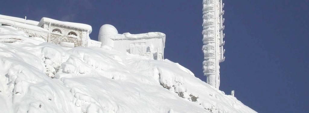
 Power Handling Capability Environment (wind, ice, temperature) Optical")
3 Antenna Prinziples The Antenna matches the electromagnetic wave of a line to the free space Parameters, that define the design of an antenna: Gain, Pattern (coverage) Frequency (size) Polarization (linear, circular) Bandwidth (Pattern, Impedance) Power Handling Capability Environment (wind, ice, temperature) Optical Appearance 3

4 Broadcast means mainly omni-directional antennas 1x Backbone 1x Transmitter 1x Site Acquisition Infrastructure costs divided by many users Large cell broadcast high power antenna mainly omni-directional one large height site Revenue per Mbyte Revenue per MHz SMS Mobile Voice Fixed Broadband Broadcast Throughput Small cell broadcast low power antenna mainly directional antenna many low height sites gap filler, transposer, repeater... 4
5 Omni-directional antennas Top mount: Vertical pattern 470 MHz) 1 λ/2 dipol ideal pattern Side mount: 2 λ/2 dipols (1150 mm) 4 λ/2 dipols (2300 mm) other solutions are necessary... 8 λ/2 dipols (4600 mm) 5
6 Sector antenna as a component for omni-directional antennas Dipole array as basic element for various pattern: - broadband - high power handling - optimized for smooth group pattern shaping ϕ 6 db = 90 Antenna pattern of a sector antenna for DVB-H at 600 MHz covering a 90 sector 6
7 Omni-directional antennas consisting of 4 sector antennas r r = 280 mm r/λ = 0.56 r = 500 mm r/λ = 1 r E res = 0.74 minima < -6 db for r >λ 7
8 Omnidirectional Antennas on a mast with large diameter r = 1000 mm r = 1000 mm r/λ = 2 r r/λ = 2 r minima < -10 db for r > 2λ 14 Panels needed for minima < -2 db 8
9 Omni-directional antennas with sector-antennas in skew arrangement Tangential radiation r + only 4 antennas necessary + cost effective - sensitive to mechanical tolerances (not possible for L-Band) - small band (only for 1-2 channels) - very careful installation required r = 1100 mm r = 2540 mm 9

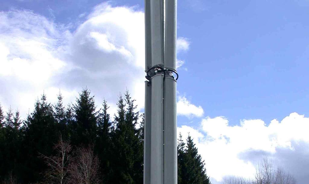
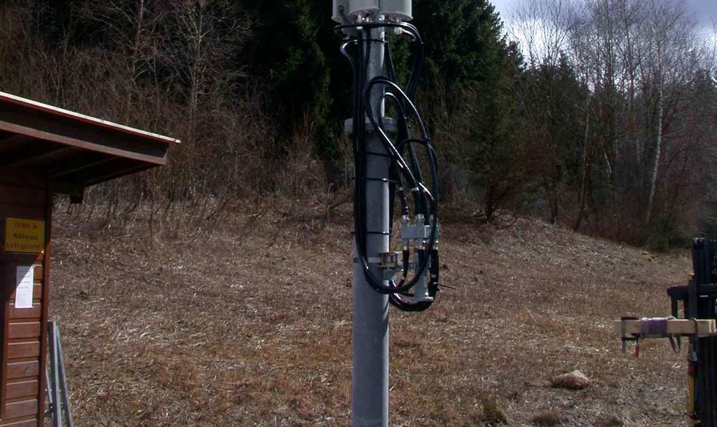

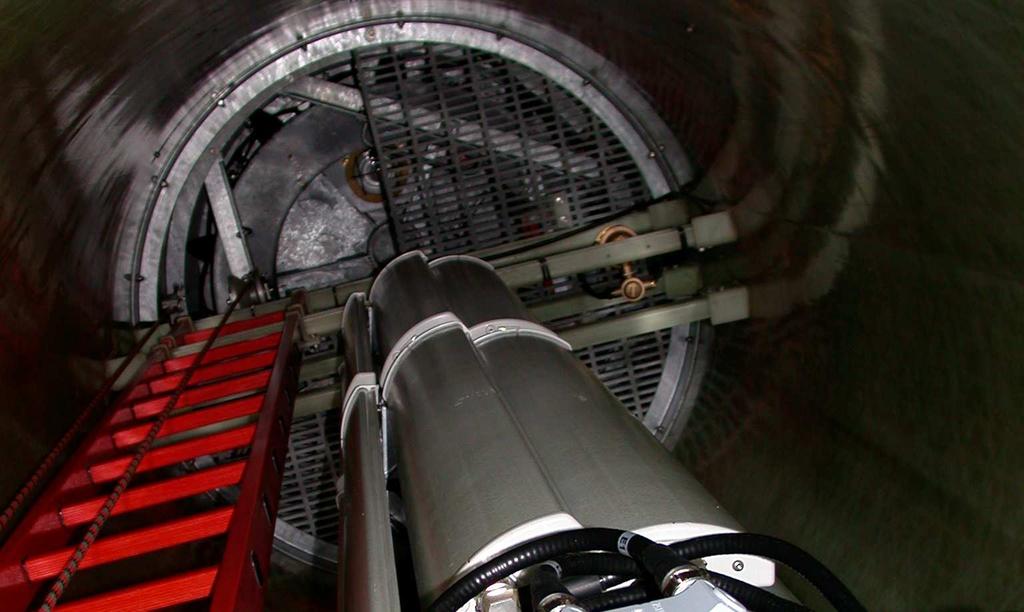
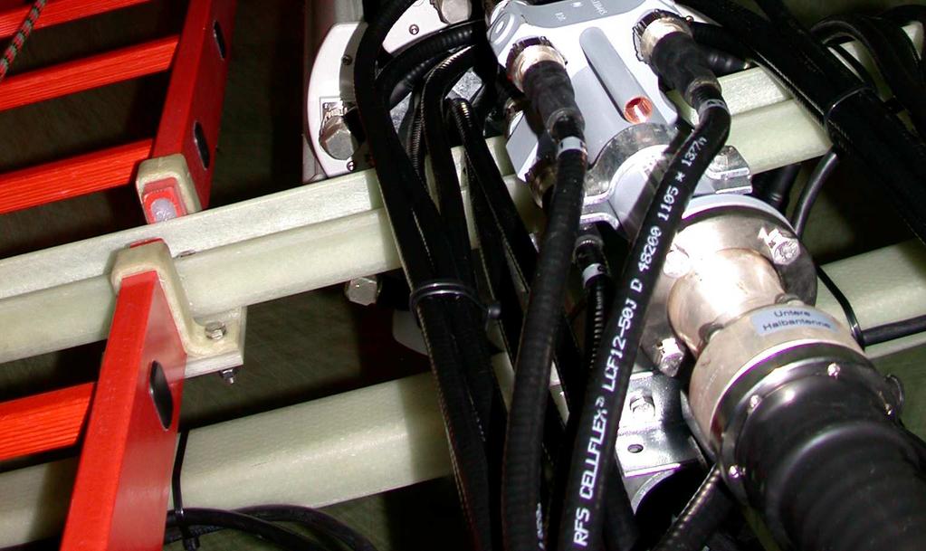
10 Omni-directional antenna examples (DMB L-Band) 2 bays of 4 antennas round a mast 2 bays of 8 antennas round a mast in a GRP Zylinder (Radom, 1.6 m) 10
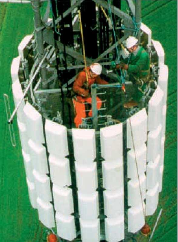
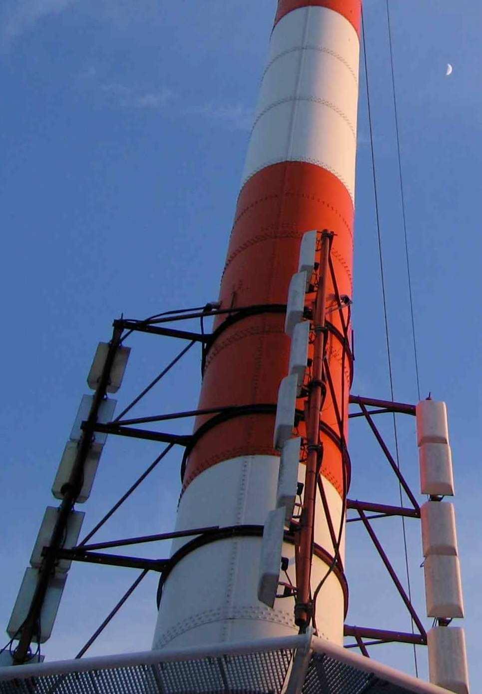
11 Omni-directional antenna exampes 16 panels /bay Skew Antenna 11

![180 ) Nulls: φ = arcsin [± (2k+1)λ/2d] Maxima: φ = arcsin [± kλ/d] k = 0, 1, 2,.](/docs-images/87/95030170/images/12-2.jpg ".. d =10λ = 20 * λ/2 ->40 lobes φ > increase number of lobes and zeros ϕ d d =")
12 Try to live with interference - Two point sources - Quasi Omni Increase Distance between elements > decrease angle for first zero (phase difference ϕ = 180 ) Nulls: φ = arcsin [± (2k+1)λ/2d] Maxima: φ = arcsin [± kλ/d] k = 0, 1, 2,... d =10λ = 20 * λ/2 ->40 lobes φ > increase number of lobes and zeros ϕ d d = 20λ 12

13 Quasi omni-directional antennas with sector-antennas 4 sector antennas round a mast of large diameter r = 50 λ, f.e. 10 m for DBM L- Band Nulls: 1 / 90 m in 5 km interference region filled up with reflections r mean value of field strength 6 db less 13
 2 x 180 Sector")
14 Omnidirectional Antennas build with 2 x 180 secto r-antennas mean value of field strength more constant Antenne with HPBW = 180 r = 5 m (25 λ) 2 x 180 Sector Antennas 14

15 Optimised design by using dual polarized antennas 4 sector antennas round a mast r = 100 λ, f.e. 20 m for DBM L- Band r

16 Adjacent antennas with dual polarization r = 10 λ 16

 Handy - how polarized?")
17 Adjacent antennas with dual polarisation maximum of the horizontal polarized E-Field minimum of the vertical polarized E-Field Antenna system radiates two orthogonal polarisation: linear: vertical, horizontal slant 45, slant -45 circular: left, right Resulting polarization at coverage zone: elliptical changing in space and frequency Polarization diversity for maximum receiving signal (car) Handy - how polarized? Rooftop antennas 17
18 Comparison dual-polarisation / vertical polarisation small variation of field-strength if dual polarization is used intereferenc causes nulls in urban area filling up due reflexions 18
19 Results of L-Band DMB-System Frankfurt Route: Frankfurter Kreuz A5 Ausfahrt Friedberg TX: vertical polarized RX: vertical polarized Fahrtstrecke in km Route: Frankfurter Kreuz A5 Ausfahrt Friedberg TX: dual polarized RX: vertical polarized Fahrtstrecke in km 19


20 Dual polarized antennas for GAP-Fillers (SFN analog repeater)... another scope of application... main transmitter polarizations-decoupling between receiving and transmitting antenna increases system performance Ch33 H-Pol V-Pol RX TX Ch33 overlap zone: orthogonal polarization will reduce interference problems 20
21 Summary Single polarized quasi-omni antennas only for: urban areas (reflections of buildings) distance from transmitting station not too far distance of adjacent antennas >> λ Dual polarized quasi-omni antennas can be used: in urban and suburban areas distance of adjacent antennas >= λ receiving antenna should receive every polarisation Dual polarized antenna for SFN gap-filler and shadow network: polarizations-decoupling between overlapping areas of transmitter and repeater cell reduces interference problems of coverage polarizations-decoupling between receiving and transmitting antenna increases system performance 21


22 Every Antenna, which fits in frequency and power can be used... DVB-H MHz DMB L-Band 22

23 23
Antenna Technology Bootcamp. NTA Show 2017 Denver, CO
 Antenna Technology Bootcamp NTA Show 2017 Denver, CO Review: How a slot antenna works The slot antenna is a TEM-Mode coaxial structure. Coupling structures inside the pylon will distort and couple to the
Newsletter 4.4. Antenna Magus version 4.4 released! Array synthesis reflective ground plane addition. July 2013
 Newsletter 4.4 July 2013 Antenna Magus version 4.4 released! We are pleased to announce the new release of Antenna Magus Version 4.4. This release sees the addition of 5 new antennas: Horn-fed truncated
Sigma Wireless Technologies Ltd McKee Avenue Finglas, Dublin 11 Ireland Phone: Fax:
 Sigma Wireless Technologies Ltd McKee Avenue Finglas, Dublin 11 Ireland Phone: + 353 1 8142050 Fax: + 353 1 8142051 Email: info@sigma.ie www.sigmawireless.ie ANTENNA SYSTEM DESIGN 800MHZ Contents 1 INTRODUCTION...4
TPV-SFN Series Low RFR VHF Slot Pylon Antennas
 Channel 7-13 (Band III) Low RFR VHF Slot Antenna Omni-directional and Directional Patterns Available Top or Side Mount Models Horizontal, Elliptical, or Circular Polarization Available TPV-SFN Series Low
360 inches (915 cm) 240 inches (610 cm) 120 inches (305 cm) 240 inches is the recommended pole length, 360 inches is the recommended free space area
 240 inches (610 cm) 120 inches (305 cm) 240 inches is the recommended pole length, 360 inches is the recommended free space area") FML C/P FM Antenna Right hand C/P Polarization Low wind load area Up to 1 kw Rating per bay Omni-directional Up to 8 kw input per array with power divider options The FML series of antennas are narrow
FML C/P FM Antenna Right hand C/P Polarization Low wind load area Up to 1 kw Rating per bay Omni-directional Up to 8 kw input per array with power divider options The FML series of antennas are narrow
Monopole Antennas. Prof. Girish Kumar Electrical Engineering Department, IIT Bombay. (022)
") Monopole Antennas Prof. Girish Kumar Electrical Engineering Department, IIT Bombay gkumar@ee.iitb.ac.in (022) 2576 7436 Monopole Antenna on Infinite Ground Plane Quarter-wavelength monopole Antenna on
Monopole Antennas Prof. Girish Kumar Electrical Engineering Department, IIT Bombay gkumar@ee.iitb.ac.in (022) 2576 7436 Monopole Antenna on Infinite Ground Plane Quarter-wavelength monopole Antenna on
DL Series UHF Top Mount Slot Antennas
 Low Group Delay True Center Fed Design Wide Range of Standard And Custom Azimuth Patterns Available In 8 To 32 Bay Models, In 2 Bay Increments to 65 kw Input Power Ratings Horizontal, Elliptical and Circular
700 and 800 MHz Band Slot Antennas
 Low Group Delay, Wide Bandwidth UHF Slot Antennas Omni-directional and Directional Patterns Available Low RFR Models Available Top or Side Mount Models Horizontal, Elliptical, or Circular Polarization
4.4. Experimental Results and Analysis
 4.4. Experimental Results and Analysis 4.4.1 Measurement of the IFA Against a Large Ground Plane The Inverted-F Antenna (IFA) discussed in Section 4.3.1 was modeled over an infinite ground plane using
Antenna Design Seminar
 Antenna Design Seminar What we are going to cover This seminar will cover the design concepts of a variety of broadcast antennas that relates to the design of TV and FM antennas. We will first look at
Using the epmp Link Budget Tool
 Using the epmp Link Budget Tool The epmp Series Link Budget Tool can offer a help to determine the expected performances in terms of distances of a epmp Series system operating in line-of-sight (LOS) propagation
P300/P350 Series. Vertically Polarized FM Antenna. Features. Characteristics
 Vertically Polarized FM Features Low VSWR, superior VSWR band width, minimal weather related VSWR problems Fully pressurized, internal feed, welded feed connections, series fed radiating elements High
Rec. ITU-R F RECOMMENDATION ITU-R F *
 Rec. ITU-R F.162-3 1 RECOMMENDATION ITU-R F.162-3 * Rec. ITU-R F.162-3 USE OF DIRECTIONAL TRANSMITTING ANTENNAS IN THE FIXED SERVICE OPERATING IN BANDS BELOW ABOUT 30 MHz (Question 150/9) (1953-1956-1966-1970-1992)
HyperLink Wireless 2.4/ 5 GHz Dual Band / Dual Polarized Omni Antenna Model: HG DPU
 HyperLink Wireless 2.4/ 5 GHz Dual Band / Dual Polarized Omni Antenna Model: HG2458-11DPU Applications 2.4/5 GHz IEEE 802.11a/b/g applications Supports 1x2, 2x2 and 4x4 MIMO AP/Routers WiMax, WISP and
The Spectrum Repack: Is there a move to VHF in your future? Bill Ammons Broadcasters Clinic 2016
 The Spectrum Repack: Is there a move to VHF in your future? Bill Ammons Broadcasters Clinic 2016 Maybe a move to VHF in your future? A quick look back at the analog era model, what worked, what did not
ECC Recommendation (16)04
04") ECC Recommendation (16)04 Determination of the radiated power from FM sound broadcasting stations through field strength measurements in the frequency band 87.5 to 108 MHz Approved 17 October 2016 Edition
ECC Recommendation (16)04 Determination of the radiated power from FM sound broadcasting stations through field strength measurements in the frequency band 87.5 to 108 MHz Approved 17 October 2016 Edition
First DTV Antenna on the Hancock Building Chicago, USA
 FRONT COVER (Front Cover Photo) UHF Top-mount Combined Antenna System Highest Power Antenna in Asia (Jakarta, Indonesia) First DTV Antenna on the Hancock Building Chicago, USA JAMPRO ANTENNAS, INC. Your
EISCAT Scientific Association Technical Specification and Requirements for Antenna Unit V 2.0
 EISCAT Scientific Association Technical Specification and s for Antenna Unit V 2.0 1. Technical Specification for Antenna Unit The EISCAT Scientific Association, also called "EISCAT" throughout this document,
Antennas & Transmission Lines
 Antennas & Transmission Lines Network Startup Resource Center www.nsrc.org These materials are licensed under the Creative Commons Attribution-NonCommercial 4.0 International license (http://creativecommons.org/licenses/by-nc/4.0/)
The better WLAN Radio Network by an optimal Antenna System
 The better WLAN Radio Network by an optimal Antenna System BU Antennas ASY H&S Antennen mme / Pfad...ppt 1 www.hubersuhner.com www.hubersuhner.com The better radio network by optimal antennas What is an
The Reverse Polarity TNC(m) RF connector can be easily secured or removed from equipment in the field by a single gloved hand, no tools required.
 RF connector can be easily secured or removed from equipment in the field by a single gloved hand, no tools required.") Overview Southwest Antennas is a half wave dipole omni antenna with a frequency range of 1.35 to 1.40 GHz and 2.15 dbi of peak gain. This product features an integrated RF bandpass filter to help eliminate
Overview Southwest Antennas is a half wave dipole omni antenna with a frequency range of 1.35 to 1.40 GHz and 2.15 dbi of peak gain. This product features an integrated RF bandpass filter to help eliminate
Broadcast Antenna & Service Guide
 Telecommunications Broadcast Antenna & Service Guide Multiple Solutions Various Patterns and Gain Coaxial, Dipole and Patch Designs www.alivetele.com 2 Alive Telecom - Variety of Antenna System Solutions
UHF Band IV-V TV Antennas I230E Series -4 dipoles Panels-
 Broadcast Antennas TV UHF UHF Band IV-V TV Antennas I230E Series -4 dipoles Panels- Electrical characteristics I230 EH I230 EV I230 EC Frequency range (MHz) 470-860 Input impedance (ohm) 50 Horizontal
Antennas Prof. Girish Kumar Department of Electrical Engineering India Institute of Technology, Bombay. Module - 1 Lecture - 1 Antennas Introduction-I
 Antennas Prof. Girish Kumar Department of Electrical Engineering India Institute of Technology, Bombay Module - 1 Lecture - 1 Antennas Introduction-I Hello everyone. Welcome to the exciting world of antennas.
Fourth Year Antenna Lab
 Fourth Year Antenna Lab Name : Student ID#: Contents 1 Wire Antennas 1 1.1 Objectives................................................. 1 1.2 Equipments................................................ 1
Case Study. Helping Norway maximise spectrum resources. Enter. Author: Cyprien de Cosson BEng MIET. September Solutions in Radiocommunications
 Case Study Helping Norway maximise spectrum resources Enter Author: Cyprien de Cosson BEng MIET September 2011 Solutions in Radiocommunications me Executive An auction always needs lots in this case, lots
EC ANTENNA AND WAVE PROPAGATION
 EC6602 - ANTENNA AND WAVE PROPAGATION FUNDAMENTALS PART-B QUESTION BANK UNIT 1 1. Define the following parameters w.r.t antenna: i. Radiation resistance. ii. Beam area. iii. Radiation intensity. iv. Directivity.
Advanced Test Equipment Rentals ATEC (2832)
") Established 1981 Advanced Test Equipment Rentals www.atecorp.com 800-404-ATEC (2832) LOG PERIODIC DIPOLES 20 MHz - 18 GHz TRANSMIT - RECEIVE SPECIFICATIONS ELECTRICAL Impedance: 50 ohms INDIVIDUALLY CALIBRATED
Established 1981 Advanced Test Equipment Rentals www.atecorp.com 800-404-ATEC (2832) LOG PERIODIC DIPOLES 20 MHz - 18 GHz TRANSMIT - RECEIVE SPECIFICATIONS ELECTRICAL Impedance: 50 ohms INDIVIDUALLY CALIBRATED
VectaStar 3500 METHODS FOR SUCCESSFUL ANTENNA DEPLOYMENT
 VectaStar 3500 METHODS FOR SUCCESSFUL ANTENNA DEPLOYMENT Cambridge Broadband Limited D000114 Issue A01 Mark Jackson 1 INTRODUCTION 3 1.1 The purpose of antennas 3 2 ANTENNA CHARACTERISTICS 4 2.1 Antenna
Abstract. Propagation tests for land-mobile radio service
 Abstract Propagation tests for land-mobile radio service VHF (200MHz) and UHF (453, 922, 1310, 1430, 1920MHz) Various situations of irregular terrain/environmental clutter The results analyzed statistically
AIR BAND ANTENNAS SUMMARY
 SUMMARY Collinear 85 140 MHz, any 5% Coaxial Dipoles 118 136 MHz, any 3% Sidemount Dipoles 118 136 MHz Stack Dipole Arrays 118 136 MHz Monocones 118 136 MHz Discones 70 1000 MHz G12 Air Band Collinear
6 Radio and RF. 6.1 Introduction. Wavelength (m) Frequency (Hz) Unit 6: RF and Antennas 1. Radio waves. X-rays. Microwaves. Light
 Frequency (Hz) Unit 6: RF and Antennas 1. Radio waves. X-rays. Microwaves. Light") 6 Radio and RF Ref: http://www.asecuritysite.com/wireless/wireless06 6.1 Introduction The electromagnetic (EM) spectrum contains a wide range of electromagnetic waves, from radio waves up to X-rays (as
6 Radio and RF Ref: http://www.asecuritysite.com/wireless/wireless06 6.1 Introduction The electromagnetic (EM) spectrum contains a wide range of electromagnetic waves, from radio waves up to X-rays (as
700 MHz MiMO Yagi Antenna
 Seriously Smart Radios for Linking Critical Communications Infrastructure 700 MHz MiMO Yagi Antenna The 700 MHz MiMO Yagi Antenna with Dual Polarization is a high gain, premium quality antenna with excellent
Antenna Fundamentals Basics antenna theory and concepts
 Antenna Fundamentals Basics antenna theory and concepts M. Haridim Brno University of Technology, Brno February 2017 1 Topics What is antenna Antenna types Antenna parameters: radiation pattern, directivity,
Antennas. You re heard, loud and clear.
 Antennas You re heard, loud and clear. PIM-RATED ANTENNAS COL Series VHF and UHF Meander Collinear The Meander Collinear Antennas, available in both the VHF, UHF and 700/800 MHz bands, have been specifically
MikroTik User Meeting 2016
 MikroTik User Meeting 2016 Topic Quality Considerations in Wireless Networking 25-26 / 02 / 2016 Ljubljana, Slovenia mmb-0518 Slide # 1 Presented by Michel Bodenheimer E-mail: michel.bodenheimer@mtiwe.com
Wideband Quasi-Omni Antenna
 DATA SHEET Two foot (0.5 m), two port, quasi-omni antenna with uniform horizontal beamwidths covering the extended band from 1710-2690 MHz 360 of coverage area across all bands of operation in a single
LINK RESEARCH ANTENNA PRODUCT MANUAL. Antennas for Digital ENG applications
 LINK RESEARCH ANTENNA PRODUCT MANUAL Antennas for Digital ENG applications Contact: Link Research Main +44 (0) 1923 474 060 Support +44 (0) 1923 474 099 Web: www.linkres.co.uk Contents 3: Flexible omni
EEM.Ant. Antennas and Propagation
 EEM.ant/0304/08pg/Req: None 1/8 UNIVERSITY OF SURREY Department of Electronic Engineering MSc EXAMINATION EEM.Ant Antennas and Propagation Duration: 2 Hours Spring 2003/04 READ THESE INSTRUCTIONS Answer
Multi-Band Quasi-Omni Antenna
 DATA SHEET Two foot (0.6 m), multi-band, four port quasi-omni antenna with 360 of coverage, covering 698-896 MHz and 1710-2360 MHz frequencies Two wide high band ports covering 1710-2360 MHz and two wide
MHz Base Station Antennas for Mobile Communications
 27 512 MHz Base Station Antennas for Mobile Communications Photo on title page: Applications for TETRA. Catalogue Issue /4 All data published in previous catalog issues hereby becomes invalid. We reserve
SET Congress Sao Paulo 24 August in the 700 MHz band
 SET Congress Sao Paulo 24 August 2014 Study of LTE interference into DTT in the 700 MHz band Mats Ek mats.ek@progira.com Content of Presentation 1. Overview /introduction 2. Interference basics 3. The
Antenna Selector & Configurator
 6 February 2018 Antenna Selector & Configurator User Manual for Antenna Selector & Configurator (Short Version) Antenna Selector & Configurator Visit our Home Page www.kathrein.com Go to Section "Broadcast
REFERENCE GUIDE External Antennas Guide 1
 REFERENCE GUIDE External s Guide 1 Xirrus External s Guide Overview To optimize the overall performance of a Xirrus WLAN in an outdoor deployment it is important to understand how to maximize coverage
A Compact Dual-Polarized Antenna for Base Station Application
 Progress In Electromagnetics Research Letters, Vol. 59, 7 13, 2016 A Compact Dual-Polarized Antenna for Base Station Application Guan-Feng Cui 1, *, Shi-Gang Zhou 2,Shu-XiGong 1, and Ying Liu 1 Abstract
Antennas & wave Propagation ASSIGNMENT-I
 Shri Vishnu Engineering College for Women :: Bhimavaram Department of Electronics & Communication Engineering Antennas & wave Propagation 1. Define the terms: i. Antenna Aperture ii. Beam Width iii. Aperture
LPLT BROADCAST NETWORKS WITH FREQUENCY REUSE 1
 LPLT BROADCAST NETWORKS WITH FREQUENCY REUSE 1 SFN/MFN Interference analysis for Fixed and Mobile reception European Commission Oct.. 23 2014 CONTENT Background and Objectives Analysis of the different
UNIT-3. Ans: Arrays of two point sources with equal amplitude and opposite phase:
 `` UNIT-3 1. Derive the field components and draw the field pattern for two point source with spacing of λ/2 and fed with current of equal n magnitude but out of phase by 180 0? Ans: Arrays of two point
MHz Base Station Antennas for Mobile Communications
 27 512 27 512 MHz Base Station Antennas for Mobile Communications Photo on title page: Applications for TETRA. Catalogue Issue 2/27 All data published in previous catalog issues hereby becomes invalid.
Antenna Overview. Version /10/20
 Antenna Overview Version 2.8 2010/10/20 Contents ANT-Ceiling-Mimo-2G for 802.11n AP Order No.: 5510000209...3 ANT-Omni-4-dual Order No.: 600529...4 ANT-RSMA.KS-D-060-03-1m Order No.: 600402...5 ANT-Omni-vehicle-1.2m
BROADBAND AND HIGH GAIN OMNIS
 C WDA series antennas are optimized for both broadband and high gain performance. These antennas are ideally suited for use with frequency hopping radios and wideband jammers where tuning or band switching
Optimizing TV Transmitting Antennas for ATSC-M/H Mobile TV
 Optimizing TV Transmitting Antennas for ATSC-M/H Mobile TV By: Bill Ammons B i l l An under the Radome look at antenna design to optimize ATSC- We will take a look at: M/H transmission Azimuth Pattern
Band I (Low VHF) TV Panel Arrays MHz. 606L Series BROADCAST ANTENNA SYSTEMS
 TV Panel Arrays MHz. 606L Series BROADCAST ANTENNA SYSTEMS") Band I (Low VHF) TV Panel Arrays 44-88 MHz L Series The L series of panels are low wind load antennas suitable to provide a customized coverage for any single TV channel in Band I. Low wind load Pressurizable
Band I (Low VHF) TV Panel Arrays 44-88 MHz L Series The L series of panels are low wind load antennas suitable to provide a customized coverage for any single TV channel in Band I. Low wind load Pressurizable
Radio Network Planning for Outdoor WLAN-Systems
 Radio Network Planning for Outdoor WLAN-Systems S-72.333 Postgraduate Course in Radio Communications Jarkko Unkeri jarkko.unkeri@hut.fi 54029P 1 Outline Introduction WLAN Radio network planning challenges
Autumn Main Exam SEAT NUMBER: STUDENTNUMBER: L--- ~~--~--~--~----~--~--L-~ SURNAME: (FAMILY NAME) OTHER NAMES: LECTURER NAME:
 OTHER NAMES: LECTURER NAME:") Autumn 216- Main Exam SEAT NUMBER: iuts UNIVERSITY OF TECHNOLOGY SYDNEY STUDENTNUMBER: L--- ~~--~--~--~----~--~--L-~ SURNAME: (FAMILY NAME) OTHER NAMES: LECTURER NAME: This paper and all materials issued
Autumn 216- Main Exam SEAT NUMBER: iuts UNIVERSITY OF TECHNOLOGY SYDNEY STUDENTNUMBER: L--- ~~--~--~--~----~--~--L-~ SURNAME: (FAMILY NAME) OTHER NAMES: LECTURER NAME: This paper and all materials issued
5G Antenna Design & Network Planning
 5G Antenna Design & Network Planning Challenges for 5G 5G Service and Scenario Requirements Massive growth in mobile data demand (1000x capacity) Higher data rates per user (10x) Massive growth of connected
White Paper. 850 MHz & 900 MHz Co-Existence. 850 MHz Out-Of-Band Emissions Problem xxxx-xxxreva
 White Paper 850 MHz & 900 MHz Co-Existence 850 MHz Out-Of-Band Emissions Problem 2016 xxxx-xxxreva White Paper 850 MHz & 900 MHz Coexistence - 850 MHz Out-of-Band Emissions Problem Table of Contents Introduction
REFERENCE GUIDE External Antennas Guide 1
 REFERENCE GUIDE External s Guide 1 Xirrus External s Guide Overview To optimize the overall performance of a Xirrus WLAN in an outdoor deployment it is important to understand how to maximize coverage
This Antenna Basics reference guide includes basic information about antenna types, how antennas work, gain, and some installation examples.
 Antenna Basics This Antenna Basics reference guide includes basic information about antenna types, how antennas work, gain, and some installation examples. What Do Antennas Do? Antennas transmit radio
The TV Spectrum Re-Packing Antenna Engineering Guide V2.0
 The TV Spectrum Re-Packing Antenna Engineering Guide V2.0 Micronetixx is pleased to present this updated engineering guide to the TV Broadcast Industry. Many veterans of the Industry that work in the RF
INTRODUCTION OF RADIO MICROPHONE APPLICATIONS IN THE FREQUENCY RANGE MHz
 European Radiocommunications Committee (ERC) within the European Conference of Postal and Telecommunications Administrations (CEPT) INTRODUCTION OF RADIO MICROPHONE APPLICATIONS IN THE FREQUENCY RANGE
Development of a noval Switched Beam Antenna for Communications
 Master Thesis Presentation Development of a noval Switched Beam Antenna for Communications By Ashraf Abuelhaija Supervised by Prof. Dr.-Ing. Klaus Solbach Institute of Microwave and RF Technology Department
4.4.3 Measurement of the DIFA Against Conducting Boxes of Various Size. Gap
 4.4.3 Measurement of the DIFA Against Conducting Boxes of Various Size In Section 4.3.3, the IFA and DIFA were modeled numerically over wire mesh representations of conducting boxes. The IFA was modeled
SCHWARZBECK MESS - ELEKTRONIK An der Klinge 29 D Schönau Tel.: 06228/1001 Fax.: (49)6228/1003
6228/1003") Calibration of Vertical Monopole Antennas (9kHz - 30MHz) 11112gs VAMPINFO 1. Introduction Vertical Monopole Antennas are used for the measurement of the electric component of EM fields, especially in the
Calibration of Vertical Monopole Antennas (9kHz - 30MHz) 11112gs VAMPINFO 1. Introduction Vertical Monopole Antennas are used for the measurement of the electric component of EM fields, especially in the
PLANNING CHALLENGES. LTE Forum Warsaw, Poland
 PLANNING CHALLENGES LTE Forum Warsaw, Poland 24.11.2011 ATDI in a few words ATDI is a French company with more than 20 years of experience in the industry Provides software and services in radio communication
L-Band and X-Band Antenna Design and Development for NeXtRAD
 L-Band and X-Band Antenna Design and Development for NeXtRAD S. T. Paine, P. Cheng, D. W. O Hagan, M. R. Inggs, H. D. Griffiths* Department of Electrical Engineering Radar Remote Sensing Group University
An Introduction to Antennas
 May 11, 010 An Introduction to Antennas 1 Outline Antenna definition Main parameters of an antenna Types of antennas Antenna radiation (oynting vector) Radiation pattern Far-field distance, directivity,
ATSC 3.0 Boosting the Signal Strength - MISO
 ATSC 3.0 Boosting the Signal Strength - MISO John L. Schadler VP Engineering Dielectric LLC Raymond, ME. Abstract - The new ATSC 3.0 broadcast standard will provide new transmission capabilities. Broadcasters
Single Frequency Network Structural Aspects & Practical Field Considerations
 Single Frequency Structural Aspects & Practical Field Considerations November 2011 Featuring GatesAir s Rich Redmond Chief Product Officer Copyright 2015 GatesAir, Inc. All rights reserved. Single frequency
Analysis of RF requirements for Active Antenna System
 212 7th International ICST Conference on Communications and Networking in China (CHINACOM) Analysis of RF requirements for Active Antenna System Rong Zhou Department of Wireless Research Huawei Technology
UNIT Write short notes on travelling wave antenna? Ans: Travelling Wave Antenna
 UNIT 4 1. Write short notes on travelling wave antenna? Travelling Wave Antenna Travelling wave or non-resonant or aperiodic antennas are those antennas in which there is no reflected wave i.e., standing
RECOMMENDATION ITU-R BS.80-3 * Transmitting antennas in HF broadcasting
 Rec. ITU-R BS.80-3 1 RECOMMENDATION ITU-R BS.80-3 * Transmitting antennas in HF broadcasting (1951-1978-1986-1990) The ITU Radiocommunication Assembly, considering a) that a directional transmitting antenna
The Benefits of BEC s Antenna Design
 The Benefits of BEC s Antenna Design Overview The explosive growth of wireless data communications is fast emerging with high peak data rates, which require superior antenna performance and design to support
Antennas 1. Antennas
 Antennas Antennas 1! Grading policy. " Weekly Homework 40%. " Midterm Exam 30%. " Project 30%.! Office hour: 3:10 ~ 4:00 pm, Monday.! Textbook: Warren L. Stutzman and Gary A. Thiele, Antenna Theory and
Characteristics of digital terrestrial television broadcasting systems in the frequency band MHz for frequency sharing/interference analysis
 Report ITU-R BT.2383-1 (10/2016) Characteristics of digital terrestrial television broadcasting systems in the frequency band 470-862 MHz for frequency sharing/interference analysis BT Series Broadcasting
Practical Antennas and. Tuesday, March 4, 14
 Practical Antennas and Transmission Lines Goals Antennas are the interface between guided waves (from a cable) and unguided waves (in space). To understand the various properties of antennas, so as to
65 Wideband Tri-Sector Antenna
 DATA SHEET Two foot (0.5 m), six port, tri-sector antenna each sector with uniform horizontal beamwidths covering the extended band from 1710-2690 MHz Three individual 65 sectors arranged in a cloverleaf
White Paper 850 MHz & 900 MHz Co-Existence 900 MHz Receiver Blocking Problem
 White Paper 850 MHz & 900 MHz Co-Existence 900 MHz Receiver Blocking Problem Table of Contents Introduction and Background 3 Assumptions 3 Receiver Blocking Problem 6 Conclusion 8 2 1. Introduction and
Chapter 15: Radio-Wave Propagation
 Chapter 15: Radio-Wave Propagation MULTIPLE CHOICE 1. Radio waves were first predicted mathematically by: a. Armstrong c. Maxwell b. Hertz d. Marconi 2. Radio waves were first demonstrated experimentally
The MYTHOLOGIES OF WIRELESS COMMUNICATION. Tapan K Sarkar
 The MYTHOLOGIES OF WIRELESS COMMUNICATION Tapan K Sarkar What is an Antenna? A device whose primary purpose is to radiate or receive electromagnetic energy What is Radiation? Far Field (Fraunhofer region>2l
RECOMMENDATION ITU-R P Guide to the application of the propagation methods of Radiocommunication Study Group 3
 Rec. ITU-R P.1144-2 1 RECOMMENDATION ITU-R P.1144-2 Guide to the application of the propagation methods of Radiocommunication Study Group 3 (1995-1999-2001) The ITU Radiocommunication Assembly, considering
ROTOTILLER. Circularly Polarized FM Antenna. Benefits. Characteristics
 Benefits Low VSWR, superior VSWR band width, and minimal weather related VSWR problems Fully pressurized, internal feed and welded feed connections High input power capacity Modular construction facilitates
REFERENCE GUIDE External Antennas Guide. Tel: +44 (0) Fax: +44 (0)
 Fax: +44 (0)") REFERENCE GUIDE External s Guide Xirrus External s Guide Overview To optimize the overall performance of a Xirrus WLAN in an outdoor deployment it is important to understand how to maximize coverage with
REFERENCE GUIDE External s Guide Xirrus External s Guide Overview To optimize the overall performance of a Xirrus WLAN in an outdoor deployment it is important to understand how to maximize coverage with
Lecture 2: The Concept of Cellular Systems
 Radiation Patterns of Simple Antennas Isotropic Antenna: the isotropic antenna is the simplest antenna possible. It is only a theoretical antenna and cannot be realized in reality because it is a sphere
Beamforming for 4.9G/5G Networks
 Beamforming for 4.9G/5G Networks Exploiting Massive MIMO and Active Antenna Technologies White Paper Contents 1. Executive summary 3 2. Introduction 3 3. Beamforming benefits below 6 GHz 5 4. Field performance
CIRCULAR DUAL-POLARISED WIDEBAND ARRAYS FOR DIRECTION FINDING
 CIRCULAR DUAL-POLARISED WIDEBAND ARRAYS FOR DIRECTION FINDING M.S. Jessup Roke Manor Research Limited, UK. Email: michael.jessup@roke.co.uk. Fax: +44 (0)1794 833433 Keywords: DF, Vivaldi, Beamforming,
Antenna Fundamentals. Microwave Engineering EE 172. Dr. Ray Kwok
 Antenna Fundamentals Microwave Engineering EE 172 Dr. Ray Kwok Reference Antenna Theory and Design Warran Stutzman, Gary Thiele, Wiley & Sons (1981) Microstrip Antennas Bahl & Bhartia, Artech House (1980)
HyperLink Wireless High Density 2.4/5 GHz Four Element Dual Polarized Flat Panel Antenna Model: HG HDP-4NF
 HyperLink Wireless High Density 2.4/5 GHz Four Element Dual Polarized Flat Panel Antenna Model: HG2458-13HDP-4NF Features Four independent antennas, two vertical and two horizontal Narrow beamwidth for
Cell Extender Antenna System Design Guide Lines
 Cell Extender Antenna System Design Guide Lines 1. General The design of an Antenna system for a Cell Extender site needs to take into account the following specific factors: a) The systems input and output
Antenna Overview. Version /11/19
 Antenna Overview Version 3.8 2018/11/19 Contents ANT-RSMA-Omni Set Order No.: 5510000397... 3 Antenna-Kit II WOx003n Order No.: 5520000145... 4 ANT-Omni-vehicle-1.2m Order No.: 600519... 4 ANT-Omni-5-2G-1.2m
Low Wideband Quasi-Omni Antenna
 DATA SHEET Two foot (0.7 m), singleband, two port quasi-omni antenna with 360 of coverage, covering 694-960 MHz frequencies Two wide low band ports covering 694-960 MHz in a low weight and low profile
Low Band Receiving Antennas
 Low Band Receiving Antennas (on a city lot) Ned Stearns, AA7A How do you know you need a Receive Antenna? Scenario #1 Many DX stations hear you much better than you hear them Scenario #2 When your DXerneighbor
Characteristics of Biconical Antennas Used for EMC Measurements
 Advance Topics in Electromagnetic Compatibility Characteristics of Biconical Antennas Used for EMC Measurements Mohsen Koohestani koohestani.mohsen@epfl.ch Outline State-of-the-art of EMC Antennas Biconical
4-Port Antenna Frequency Range Dual Polarization HPBW Adjust. Electr. DT Enhanced Sidelobe Suppression
 Frequency Range Dual Polarization HPB Adjust. Electr. DT Enhanced Sidelobe Suppression Y1 18dB 18dB Downtilt set by hand or by optional RCU (Remote Control Unit) X 65 2 14 X 65 2 14 4-Port Antenna / 65
db Systems Model 5100A-HS-ICE DME Antenna
 Installation Manual db Systems Model 5100A-HS-ICE DME Antenna HEATED RADOME HIGH PERFORMANCE DME ANTENNA MANUFACTURER db SYSTEMS, INC. 2005 SOUTH TURF SOD ROAD HURRICANE, UT 84737 DATE OF ORIGINAL ISSUE:
A Compact Dual-Band Dual-Polarized Antenna for Base Station Application
 Progress In Electromagnetics Research C, Vol. 64, 61 70, 2016 A Compact Dual-Band Dual-Polarized Antenna for Base Station Application Guanfeng Cui 1, *, Shi-Gang Zhou 2,GangZhao 1, and Shu-Xi Gong 1 Abstract
Week 2. Topics in Wireless Systems EE584-F 03 9/9/2003. Copyright 2003 Stevens Institute of Technology - All rights reserved
 Week Topics in Wireless Systems 43 0 th Generation Wireless Systems Mobile Telephone Service Few, high-power, long-range basestations -> No sharing of spectrum -> few users -> expensive 44 Cellular Systems
Antenna Engineering Lecture 3: Basic Antenna Parameters
 Antenna Engineering Lecture 3: Basic Antenna Parameters ELC 405a Fall 2011 Department of Electronics and Communications Engineering Faculty of Engineering Cairo University 2 Outline 1 Radiation Pattern
Antenna & Propagation. Antenna Parameters
 For updated version, please click on http://ocw.ump.edu.my Antenna & Propagation Antenna Parameters by Nor Hadzfizah Binti Mohd Radi Faculty of Electric & Electronics Engineering hadzfizah@ump.edu.my Chapter
NTT DOCOMO Technical Journal. 1. Introduction. 2. Features of an Activeantenna. 2.1 Basic Configuration of Base Station using an Active Antenna
 Active Antenna for More Advanced and Economical Radio Base Stations Base Station Active antennas that integrate radio transceiver functions in the antenna unit have been attracting attention as an approach