Installation Manual Mobile Integration System
|
|
|
- Kerry Phelps
- 5 years ago
- Views:
Transcription
1 Installation Manual Mobile Integration System Table of Contents Kit Contents... 2 Overview... 3 Installation Instructions... 6 Power up Test the System Beam Coverage Trouble Shooting Tips Appendix Motorola XTL-5000 Integration Notes
 1 Options below SATRAD-CHNB (optional) 1 #6 metal screws 4 #6 flat washers 4 Radio integration cable 1 Power cable CHNB to Matrix (20ft) 1 Cat5 cable (20ft) 1")
2 Kit Contents Description Qty SATRAD-MIS Mobile Integration System 1 Power cord 1 Cat5 cable (3ft) 1 #6 metal screws 4 #6 flat washers 4 Power cable SATRAD-G2 to Matrix (3ft) 1 Options below SATRAD-CHNB (optional) 1 #6 metal screws 4 #6 flat washers 4 Radio integration cable 1 Power cable CHNB to Matrix (20ft) 1 Cat5 cable (20ft) 1 Speaker 1 2
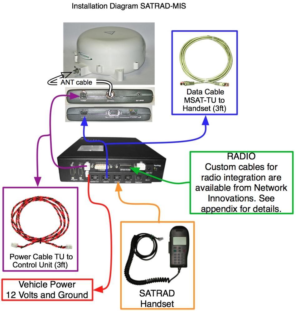
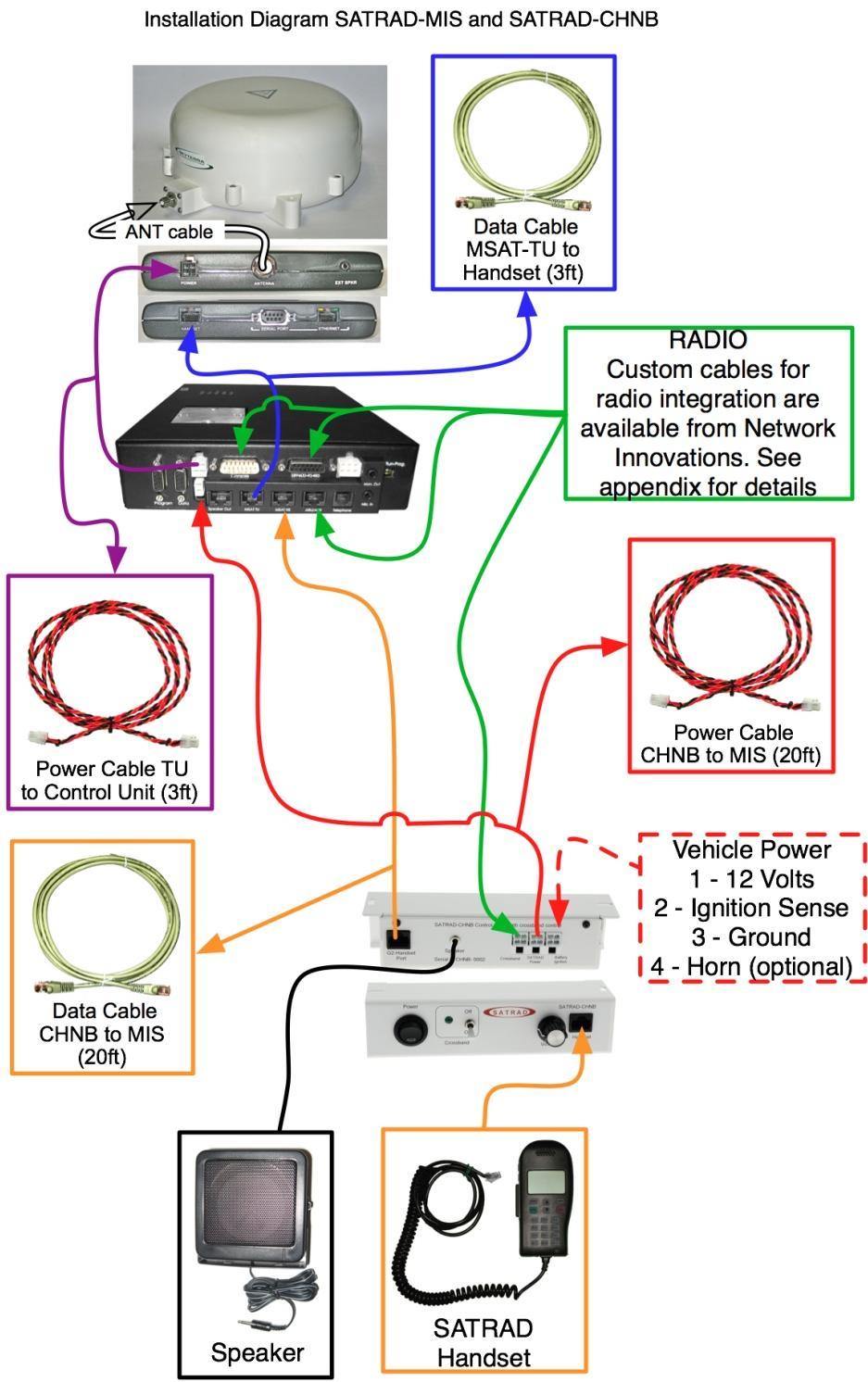
3 Overview The SATRAD MIS mobile integration system is designed for vehicle installations requiring mobile radio s to be cross-banded to the SATRAD-G2 satellite communications system. This procedure gives instructions to installing the MIS and the optional SATRAD-CHNB (control head network bridge). Antenna Installation This section describes how to install the SATRAD-G2 antenna in vehicle applications. The antenna can be purchased with optional magnetic feet attached to the antenna. These high powered magnets hold the antenna in place with a total force of 1260N (280lbf). 1) Select a mounting area on the vehicle. Keep the following considerations in mind when choosing a location. a. Must be clear of any obstruction by at least 600mm (24 inches). b. Minimal vibration area. Roof of vehicle is preferred over trunks or hoods. Custom mounts for specific applications are available. c. The antenna cable is able to be routed into the vehicle easily. d. The antenna must be horizontal. e. Keep the satellite antenna as far away from the radio antenna as possible. 2) Mount the magnetic feet to the antenna. a. Slide a flat washer on to the bolt. b. Slide a rubber washer onto the bolt. c. Insert the bolt into the 3 ceramic magnet. d. Slide a rubber washer onto the bolt. e. Slide a flat washer on to the bolt. f. Thread the bolt assembly into the MSAT-G2 antenna foot. g. Slide another flat washer onto the bolt assembly. h. Thread a Nylock nut onto the bolt assembly and tighten. i. Tighten enough only to secure the bolt to the antenna. Too much torque will cause damage to the antenna casing. j. Cover the magnet with the rubber cover. 3

4 Magnet cover not shown. Bolt Nylock nut Flat washer Rubber Washer Antenna body Flat washer Rubber Washer Magnet Rubber Washer Flat washer 4
 Route the cable through the vehicle. Using the same route as the P25 VHF/UHF radio cable is ideal. a. The cable must not become kinked or be routed through a bend radius smaller than 2.25 (57mm).")
5 3) Connect the coax cable to the antenna. a. The coaxial cable recommended is RG223. This cable has a maximum length of 20 feet (6 meters). 4) Place the antenna onto the selected location. 5) Route the cable through the vehicle. Using the same route as the P25 VHF/UHF radio cable is ideal. a. The cable must not become kinked or be routed through a bend radius smaller than 2.25 (57mm). b. The cable must be protected from any kind of damage. Avoid routing the cable under the vehicle. c. When the cable passes through a sheet metal panel use a grommet to protect the cable. 6) Connect the loose end of the coax cable to the SATRAD-G2. 5

6 Installation Instructions This section describes the installation method into vehicles. 1. Locate an area to mount the SATRAD-MIS and SATRAD-G2 on the vehicle. a. Typical location for an ambulance is behind the driver. b. Typical location for a police vehicle is in the trunk. c. If the optional SATRAD-CHNB has been purchased, locate an area near the operator. Usually under the dash is a good location. 6


7 2. Mount the SATRAD-MIS to the vehicle. Use metal screws in the locations shown below. Ensure there is room to attach wiring harnesses. a. If installing the optional SATRAD-CHNB use 2 sheet metal screws to secure it in the selected location. Bottom View of SATRAD-MIS Mounting points 7
8 3. Connect the MIS to the SATRAD-G2 transceiver, and vehicle power. a. If installing the optional SATRAD-CHNB route the vehicle power to the Ignition Battery port on the control head. Then run the power cable from the control head to the MIS. 4. Connect a handset to the port labelled MSAT-HS on the MIS. a. If installing with the optional SATRAD-CHNB route the Cat5 cable from the control head to the MSAT-HS port. 5. Connect a SATRAD-G2 handset to the handset port on the MIS. a. If using the optional SATRAD-CHNB connect to the Handset port on the control head. 6. Connect the radio to the MIS using the custom cable. a. This cable is specific to the radio installed in the vehicle. This radio must be identified at the time of order to ensure the correct cable is available. 7. If using the optional speaker connect it to the back of the SATRAD-CHNB. 8. Connect a computer serial port to the connector labelled Program. Load a terminal emulation program such as SERIALCOMM.EXE (available from Network Innovations). This will be used to monitor the initial start up self check functions. a. See section Initial Start up and Tests. 9. Remove the serial cable from the MIS. 10. Turn on the power. a. Perform qualification tests. See Test the System section. 8
9 9
10 10
11 Initial Start-up Tests Observe the terminal window when starting the system, the display should show the start up messages shown below; (the optional SATRAD-CHNB will not change this procedure). (c) Copyright Network Innovations, all rights reserved. Hardware: NI-3005d rev A Board S/N: 8063 CPU Id: R2000 rev 3 System RAM: 512 Kbytes System Flash: 512 Kbytes System Clock: :58:24 Build Date: Jan :26:27 Dynamic C Version: 9.62 Software Version: NI-3005d A F0021 (2012/01/30) P25 Radio: XTL5000 Product S/N: Serial Number: 01-25ea MAIN: Initializing Sub-systems... AUTOCAL(VM): v.dgnd=32715 v.ref=254 v.rect=32792 FAN: Init Fan... COR: init COR... PTT: Init PTT... FG: Init Function Generators... AUTOCAL(FG-1) Level Ok sin= tr= sq= AUTOCAL(FG-2) Level Ok sin= tr= sq= AUTOCAL(FG-1) Freq Ok AUTOCAL(FG-2) Freq Ok DTMF: Init DTMF... AUTOCAL(DTMF-1): Ok rdac=158 itr=7 try=0 AUTOCAL(DTMF-2): Ok rdac=157 itr=7 try=0 TW: Init Tone-watcher... AUTOCAL(VC-1): Ok rdac=149 itr=8 AUTOCAL(VC-2): Ok rdac=147 itr=8 AUTOCAL(VC-3): Ok rdac=149 itr=8 FO: Init Fail-over... SH: Init Shell... FO: Entering Pass-through Mode AUTOCAL(AF): f= Hz f.coarse=-12 f.fine=0 MAIN: Running... RDO: Earpiece Volume set to 5 RDO: GPS enabled RDO: # Talk Group RDO: RDO: 1 02 If any of the tests fail, an appropriate message will be displayed. It is not possible to repair a failed STARAD MIS in the field. Failed units should be returned to Network Innovations via an RMA. The handset will indicate progress through the initialization process, however it does not display error messages. 11

12 Power up This section describes the recommended testing steps to ensure that the installation has been properly performed. It will be helpful to have a person with another SATRAD-G2 system to perform receiving and transmit test. 1) Check the antenna, and ensure that there are no obstructions (including people, animals, trees, or buildings). 2) Connect the handset to the MSAT-HS port in the back of the MIS. 3) Turn the power on by pressing the red button on the front of the MIS. The power LED should light up. 4) Observe the LED s on the front of the MIS they all should light briefly. 5) During normal operation the LED s will act in the following manner. a) SATRAD steady on means the systems is running. b) Voice status i. Off when the PTT / COR is inactive. ii. On when the PTT /COR is pressed (push to talk request received). iii. Flashes quickly when voice data is being transmitted over the satellite (PTT is active). iv. Flashes slowly when voice data is being received over the satellite system. 12
13 c) Interface, flickers when data is being exchanged between the MIS and the SATRAD-G2. d) Satellite i. Steady on means the satellite link is established. ii. Flashing means the link is currently being created. iii. Steady off means the link is down. e) Power; on indicates power is turned on, off indicates the power is turned off. Test the System This section gives instructions on how to test the SATRAD-MIS once installed to ensure it is properly functioning. It will be helpful at this time to have a second SATRAD-G2 available to help test. 1) Press the PTT on the SATRAD hand set while at the same time observing the b LED. The LED should turn on. 2) Press the PTT button in the SATRAD handset, and speak a short message (testing ), and at the same time observe the voice status LED b. The LED should turn on, then after a few seconds the LED should flash rapidly. The handset will display USER-ON. The message should be heard on the second SATRAD-G2. Release the PTT button. 3) Request a voice transmission from the second SATRAD-G2. Observe the voice status indicator b, the LED should flash slowly. Observe the handset it should display the DN number (device number, 4 digits long) of the second SATRAD-G2. The audio should be heard at the handset. 4) At the console, select the SATRAD resource, then initiate a transmission and speak a short message. Observe the following: a. The voice indicator b should illuminate then flash quickly. b. The SATRAD handset should display USER-ON. c. The person on the second SATRAD-G2 should hear the message. 5) Request the person on the second SATRAD-G2 to transmit a voice message. Observe the following: a. The voice status indicator b should flash slowly. b. The SATRAD resource icon on the console should illuminate (where supported). c. The message is heard at the console. 13
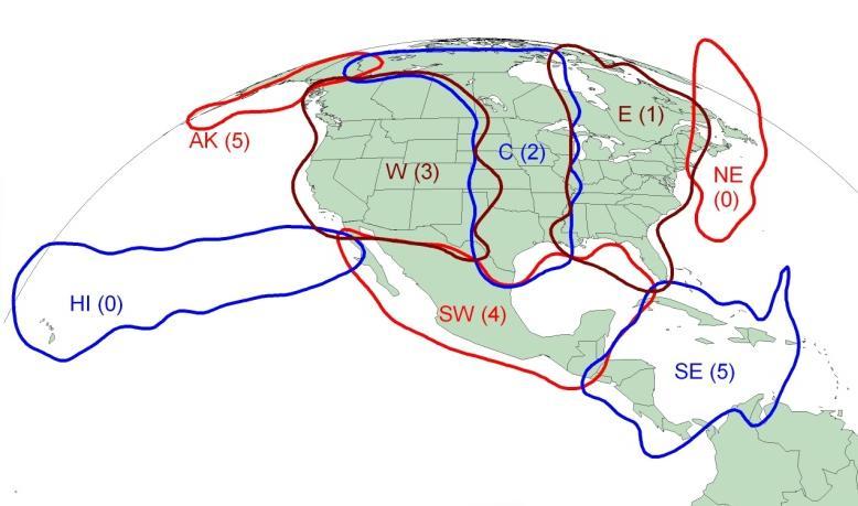
14 Beam Coverage This section details the satellite service coverage of the SATRAD system. In order to make select good installation locations review the graphic showing the approximate coverage of each beam. Note that in the fringe (between the borders of 2 beams) there can be cross over problems. Select the beam that offers the strongest signal strength. The SATRAD-MIS system automatically selects the current beam when the unit is commissioned. If the need arises to change the beam manually the MIS first needs to be placed into transparent mode. Follow the next set of instructions to change the beam. 1. Press the PWR button on the side of the handset. 2. As soon as the tone is heard release the PWR button. 3. Press the MENU key. 4. Scroll to the ADMIN selection and press select. 5. Scroll to the X-OVER selection and press select. 6. Scroll to the desired beam, and press select. 7. The system will now ask to continue, press yes. 8. Allow to the MIS to return to normal mode. The user must not press any button for 60 seconds. The MIS will reboot the transceiver, and a 2 tone beep series will be heard. 14
15 15
16 Trouble Shooting Tips The system consists of 2 key components; the SATRAD-MIS, and the SATRAD- G2. Should the system fail to operate properly, the following steps should assist in isolating the problem; 1. Read the display on the handset. a. Normal display TG:LABEL B#S## b. LABEL = talk group label. Make sure you re on the correct talk group. c. B = Beam, this should be the correct beam for the area the operator will be using the device. d. S = Signal strength, should be above 60 in order for proper functionality. 2. Disconnect the data cable from the MIS to the G2. Connect the G2 handset directly to the G2 and test for operation. 3. Review the wiring for proper interconnection. If the antenna cable is loose ensure the system is turned off before tightening. 4. Check the RUN / PROG switch and ensure that it is in the RUN position. 5. Observe the display on the monitoring computer. If the monitoring computer does not show the initialization sequence, verify connectivity by connecting a null modem to the end of the serial port cable and striking a key on the keyboard the display should show the key depressed. If the display does not show the key depressed, there is a problem with the cable or configuration of the software. Re-attach the cable to the SATRAD MTX when the problem has been corrected and power cycle the system. 6. The SATRAD-MIS is sensitive to alternator noise. If this is suspected use a capacitor to filter the noise out. 7. If the optional SATRAD-CHNB was installed temporarily disconnect it from the MIS and then test the MIS alone. For any further questions contact technical support. a. Web: b. Toll Free: c. Phone:


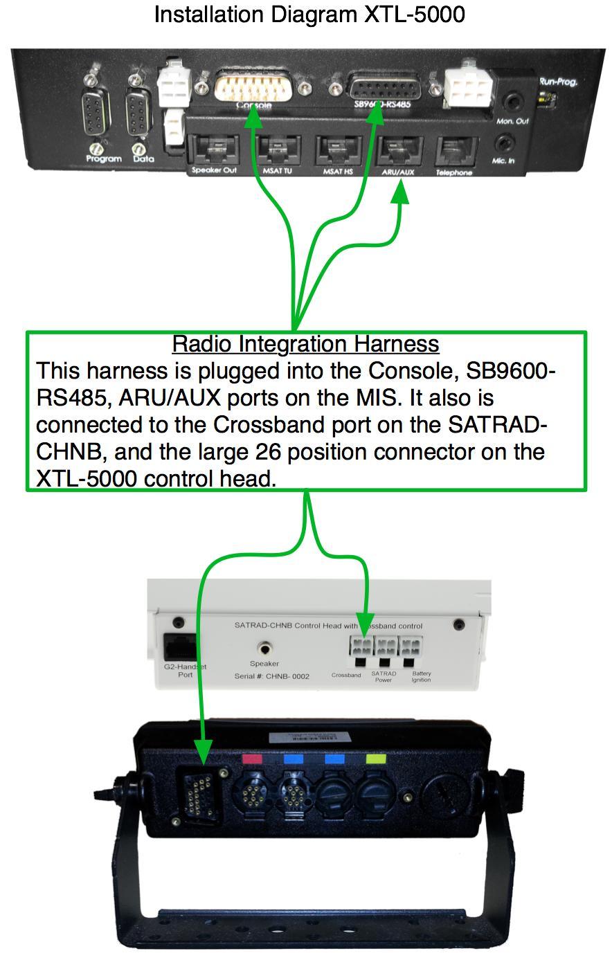
17 Appendix Motorola XTL-5000 Integration This section describes the installation of the radio integration harness for the Motorola radio XTL-5000 with the remote control head. On the back of the XTL-5000 s control head is a large 26 position connector. The radio integration harness must be plugged into this connector. 17
18 18
19 Notes 19
20 Network Innovations 4424 Manilla Road SE Calgary, Alberta T2G 4B7 Toll Free:
Installation Manual Console Integration System
 Installation Manual Console Integration System Table of Contents Kit Contents... 2 Overview... 3 Installation Instructions... 3 Typical Installation Wiring Diagram... 4 Configuring the Network Bridge...
Satellite Terminal. Installation Guide. Release 2.2 Ref. nr
 Satellite Terminal Installation Guide Release 2.2 Ref. nr. 37628 Table of Contents Table of Contents Table of Contents... 2 1 Introduction... 3 1.1 About this Guide... 3 1.2 Material Provided in the Box...
APX 6000 Portable Radio
 Montgomery County Emergency Services 800 MHz Rebanding Training Portable Radio Before You Begin View the main training video first, it covers: General Radio Review Overview of Montgomery County s Radio
Setup and Operating Procedures ICRI-9575P Incident Commanders Radio Interface
 COMMUNICATIONS-APPLIED TECHNOLOGY 11250-14 Roger Bacon Drive Reston, VA 20190 U.S.A. Voice: +1-703-481-0068 Support: Techsupport@c-at.com Setup and Operating Procedures ICRI-9575P Incident Commanders Radio
Basic Transceiver tests with the 8800S
 The most important thing we build is trust ADVANCED ELECTRONIC SOLUTIONS AVIATION SERVICES COMMUNICATIONS AND CONNECTIVITY MISSION SYSTEMS Basic Transceiver tests with the 8800S Basic Interconnects Interconnect
RMV25 / RMV50 RMU25 / RMU45
 RMV25 / RMV50 RMU25 / RMU45 Owner's Manual TABLE OF CONTENTS INTRODUCTION... 3 FCC Requirements... 3 SAFETY WARNING INFORMATION... 3 CONTROLS and INDICATORS... 5 FRONT PANEL... 5 LCD Icons and Indicators...
Rensselaer County Bureau of Public Safety 800 MHz Radio User Training. APX 4500 Mobile Radio APX 6500 Mobile Radio 02 Control Head
 Rensselaer County Bureau of Public Safety 800 Mz Radio User Training APX 4500 Mobile Radio APX 6500 Mobile Radio 02 Control ead Before You Begin View the Operations Training Presentation first, it covers:
APX 4500 Mobile Radio APX 6500 Mobile Radio 02 Control Head
 Rensselaer County Bureau of Public Safety 800 Mz Radio User Training APX 4500 Mobile Radio APX 6500 Mobile Radio 02 Control ead Before You Begin View the Operations Training Presentation first, it covers:
Montgomery County Emergency Services 800 MHz Rebanding Training. MTS 2000 Type II & III. Portable Radio
 Montgomery County Emergency Services 800 MHz Rebanding Training Portable Radio Before You Begin View the main training video first, it covers: General Radio Review Overview of Montgomery County s Radio
M2 Antenna Systems, Inc. Model No: 2M HO LOOP
 M2 Antenna Systems, Inc. Model No: 2M HO LOOP SPECIFICATIONS: Model... 2M HO LOOP Frequency Range... 144 To 144.5 MHz Gain, Typical @ 10 ft.... 4 dbd @ 10 deg. Gain, 2 STK @ 82 & 132... 8 dbd @ 9 deg.
BL-ER-P Ethernet Radio Unit for Pedestal Installation Guide
 Assemble the Antenna Riser 1. Remove the antenna riser assembly and the antenna from its packaging. 2. Remove the plastic cap, the nut, and the lock washer from the stem of the antenna. 3. Put the stem
MFJ-208 VHF SWR Analyzer
 MFJ-208 VHF SWR Analyzer Thank you for purchasing the MFJ-208 VHF SWR Analyzer. The MFJ-208 gives you a direct readout of your antenna's SWR without the need for formulas or indirect readings. The MFJ-
EDACS WALL MOUNT STATION. Maintenance Manual. Mobile Communications LBI-31838A TABLE OF CONTENTS
 A Mobile Communications EDACS WALL MOUNT STATION TABLE OF CONTENTS SYSTEM BOARD & REGULATOR BOARD.......... LBI-31892 KEY/DISPLAY BOARD MAINTENANCE MANUAL.... LBI-31940 Maintenance Manual Printed in U.S.A.
SETUP and OPERATING MANUAL ADVANCED MULTI-CHANNEL VEHICLE INTERCOM SYSTEM (AMCVIS)
") SETUP and OPERATING MANUAL Sept 23, 2010 Rev D ADVANCED MULTI-CHANNEL VEHICLE INTERCOM SYSTEM (AMCVIS) with DIGITAL CREW CONTROL and RADIO BRIDGING The AMCVIS was designed, manufactured and is supported
SETUP and OPERATING MANUAL Sept 23, 2010 Rev D ADVANCED MULTI-CHANNEL VEHICLE INTERCOM SYSTEM (AMCVIS) with DIGITAL CREW CONTROL and RADIO BRIDGING The AMCVIS was designed, manufactured and is supported
AUDIOVOX GMRS4WM Owner s/installation Manual
 AUDIOVOX GMRS4WM Owner s/installation Manual GMRS (General Mobile Radio Service) Wall Mount Charger Patent Pending www.asaelectronics.com WARNING Replacement or substitution of transistors, diodes, or
INSTALLATION INSTRUCTIONS
 TreadClimber INSTALLATION INSTRUCTIONS STAR TRAC FITNESS 1 of 14 635-4175 Rev: B NOTICE Installation of this product requires that 2 or more people are available to safely perform certain steps outlined
D3976 RECESSED EXIT INSTALLATION INSTRUCTIONS
 PACKAGE CONTENTS PRODUCT MUST BE INSTALLED ACCORDING TO ALL APPLICABLE BUILDING AND LIFE SAFETY CODES TEMPLATE INSTALLATION INSTRUCTIONS STRIKE HAND TOOL 5/32 HEX KEY ROD END CAPS EXIT DEVICE CRANK ARM
Disclaimers. Important Notice
 Disclaimers Disclaimers Important Notice Copyright SolarEdge Inc. All rights reserved. No part of this document may be reproduced, stored in a retrieval system, or transmitted, in any form or by any means,
Universal Installation Guide for MR Mini and PRO Models MRE001 MRE028 MRE033 MRE036 MRE038 MRE039 MRE040 MRE041 MRE042
 Universal Installation Guide for MR Mini and PRO Models MRE001 MRE028 MRE033 MRE036 MRE038 MRE039 MRE040 MRE041 MRE042 1 Contents Section 1: Introduction... 3 Section 2: External Aerial Installation...
VHF 100/200 Series Radio Installation Instructions
 These installation instructions are for the following VHF radios and handsets: North American Models VHF 100 VHF 200 GHS 10 International Models VHF 100i VHF 200i GHS 10i Compare the contents of this package
Hughes 9450 Mobile Satellite Terminal. Installation Guide
 Hughes 9450 Mobile Satellite Terminal Installation Guide 3004129 Revision A September 15, 2010 Copyright 2010 Hughes Network Systems, LLC All rights reserved. This publication and its contents are proprietary
RBP-1215B-RX DODGE RAM QUAD CAB RX3
 RBP-1215B-RX3 2002-2017 DODGE RAM 15-3500 QUAD CAB RX3 Passenger side RX-3 Side Step Drill Template Passenger side rear Modular Bracket (6) L Support Brackets Driver side rear Modular Bracket Driver side
9/14/2017. APX 4000 Portable Radio. Before You Begin. APX 4000: Introduction. Rensselaer County Bureau of Public Safety 800 MHz Radio User Training
 9/14/2017 Rensselaer County Bureau of Public Safety 800 MHz Radio User Training Portable Radio Before You Begin View the Operations Training Presentation first, it covers: Overview of Rensselaer County
Owner s Manual. Model G-223. GMRS/FRS Radio. FEATURES 22 Channels Scan 22 Key Pad Lock Call Alert Power HI/LO Roger Beep Tone
 Owner s Manual Model G-223 GMRS/FRS Radio FEATURES 22 Channels Scan 22 Key Pad Lock Call Alert Power HI/LO Roger Beep Tone This device complies with Part 15 of the FCC rules. Operation is subject to the
Installing the Hughes BGAN Remote Antenna
 Installing the Hughes BGAN Remote Antenna Product description BGAN Remote Antenna The Hughes BGAN Remote Antenna (HNS Part No. 9501286-0001) is designed to be permanently installed with the Basic Fixed
Star Trac Turbo Trainer Assembly & Setup
 Star Trac Turbo Trainer Use the following procedures to unpack and assemble your Turbo Trainer manufactured by Star Trac. UNPACKING AND PARTS LIST Position the shipping carton so the Heavy End logo is
COMPONENT LOCATION INDEX
 COMPONENT LOCATION INDEX 2004 ACCESSORIES & EQUIPMENT Audio System - TSX Fig. 1: Locating Audio System Components (1 Of 2) Tuesday, March 11, 2008 3:35:47 3:35:51 PM Page 1 Fig. 2: Locating Audio System
ADI-100 Interrupter. Operator s Manual. 526 S. Seminole Bartlesville, OK /
 ADI-100 Interrupter Operator s Manual 526 S. Seminole Bartlesville, OK 74003 918/336-1221 www.sescocp.com ADI - 100 Interrupter FEATURES Clock Accuracy 100% during GPS lock Clock Drift 30 µsec per degree
INSTALLATION MANUAL EXPLORER 325
 INSTALLATION MANUAL EXPLORER 325 EXPLORER 325 Document number: 98-131306-A Release date: June 17, 2010 Disclaimer Any responsibility or liability for loss or damage in connection with the use of this product
JEM Radio II Operation Guide. Manual P/N M Victor Place Colorado Springs, Colorado
 JEM Radio II Manual P/N M09999-999 2115 Victor Place Colorado Springs, Colorado 80915 800.284.0399 www.jemcom.com Table of Contents Display... 3 Channel Entry... 4 Shortcuts... 4 Text Messages... 4 Buttons...
INSTRUCTION MANUAL VHF FM TRANSCEIVER TK-7102H UHF FM TRANSCEIVER TK-8102H KENWOOD CORPORATION B (M)
") INSTRUCTION MANUAL VHF FM TRANSCEIVER TK-7102H UHF FM TRANSCEIVER TK-8102H KENWOOD CORPORATION B62-1596-00 (M) 09 08 07 06 05 04 03 02 01 00 THANK YOU! We are grateful you chose KENWOOD for your personal
INSTRUCTION MANUAL VHF FM TRANSCEIVER TK-7102H UHF FM TRANSCEIVER TK-8102H KENWOOD CORPORATION B62-1596-00 (M) 09 08 07 06 05 04 03 02 01 00 THANK YOU! We are grateful you chose KENWOOD for your personal
ic-f1020 ic-f2020 INSTRUCTION MANUAL VHF LAND MOBILE RADIO UHF LAND MOBILE RADIO
 INSTRUCTION MANUAL VHF LAND MOBILE RADIO ic-f1020 UHF LAND MOBILE RADIO ic-f2020 This device complies with Part 15 of the FCC Rules. Operation is subject to the condition that this device does not cause
Kit Kit. GeoSteer GS-900 Radio Kit. GS-900 Radio Kit Installation Instructions Rev A
 200-0652-01 Kit 200-0652-02 Kit GeoSteer GS-900 Radio Kit Item Component Part Number Qty Notes 1. Assembly, Radio GS-900 200-0642-01 (North America) 200-0642-02 (Australia) 1 Radio assembly in kit is region
INSTALLATION INSTRUCTIONS UTV LIGHT BAR KIT Part Number: and Application: All UTV s*
 INSTALLATION INSTRUCTIONS UTV LIGHT BAR KIT Part Number: 83970 and 84360 Application: All UTV s* * does not include Arctic Cat vehicles Your safety, and the safety of others, is very important. To help
MSAT-G2 Installation Guide
 Introduction... 1 Transceiver Unit (TU)... 3 Power Port... 4 Ethernet and Serial Ports... 4 RJ 45 Ethernet Port... 4 Serial Port... 5 Antenna Port... 5 Handset Port... 6 External Speaker... 6 System Power
GPS Dome Installation Manual
 GPS Dome 1.01 Installation Manual Contents Introduction... 3 Overview... 3 Cautions... 4 Installation... 4 Installation Kit... 4 GPS Rece iver System with GPS Dome... 5 SMA Cables Connectors... 5 Installation
GM350 User Guide. GM350 User Guide. Safety Information. English
 GM350 User Guide GM350 User Guide Contents Page: Safety Information...1 General Information... 2 Radio Controls/Indicators... 2 Audio Signals... 3 Display Icons...3 Radio On/Off...3 Channel Selection...
Field Hub Installation Guide. P/N Rev. C 05/15
 Field Hub Installation Guide P/N016-0171-380 Rev. C 05/15 E21714 Copyright 2015 Disclaimer While every effort has been made to ensure the accuracy of this document, Raven Industries assumes no responsibility
CON NEX HP. OWNER'S MANUAL Full Channel AM/FM Amateur Mobile Transceiver TABLE OF CONTENTS TUNING THE ANTENNA FOR OPTIMUM S.W.R..
 TABLE OF CONTENTS PAGE SPECIFICATIONS... 2 INSTALLATION... 3 LOCATION... 3 CON NEX - 4300HP MOUNTING THE RADIO... 3 IGNITION NOISE INTERFERENCE... 4 ANTENNA... 4 TUNING THE ANTENNA FOR OPTIMUM S.W.R..
TurboVUi Solo. User Guide. For Version 6 Software Document # S Please check the accompanying CD for a newer version of this document
 TurboVUi Solo For Version 6 Software Document # S2-61432-604 Please check the accompanying CD for a newer version of this document Remote Virtual User Interface For MOTOTRBO Professional Digital 2-Way
INSTALLATION AND OPERATION MANUAL. Multiple-Radio Interface Module 41021G P-26 (11-12) 2012 David Clark Company Incorporated
 2012 David Clark Company Incorporated") INSTALLATI AND OPERATI MANUAL Multiple-Radio Interface Module 41021G-01 19537P-26 (11-12) 2012 David Clark Company Incorporated Table of Contents Cautions and Warnings... 1 Parts/Tools List... 2 Supplied
INSTALLATI AND OPERATI MANUAL Multiple-Radio Interface Module 41021G-01 19537P-26 (11-12) 2012 David Clark Company Incorporated Table of Contents Cautions and Warnings... 1 Parts/Tools List... 2 Supplied
GPSR400 Quick Start Guide
 GPSR400 Quick Start Guide Rev. 6 Introduction Microlab s digital GPS repeater system can be used for cellular communications UTC synchronization for locations where the GPS signals are not readily available.
FLEXRISE2 VERSION. 2 LEG / 2 MOTOR ELECTRIC TABLE BASE (36 to 72 ) **PATENT PENDING**
 **PATENT PENDING**") FLEXRISE2 2 LEG / 2 MOTOR ELECTRIC TABLE BASE (36 to 72 ) VERSION A INSTRUCTION MANUAL CONTENTS: FLEX-MU-2L3S-C3672-K4# FEET-ADJ-UNV-2430# **PATENT PENDING** MAX Load 265 lbs (120 KG) Equally Divided MAX
FLEXRISE2 2 LEG / 2 MOTOR ELECTRIC TABLE BASE (36 to 72 ) VERSION A INSTRUCTION MANUAL CONTENTS: FLEX-MU-2L3S-C3672-K4# FEET-ADJ-UNV-2430# **PATENT PENDING** MAX Load 265 lbs (120 KG) Equally Divided MAX
User Manual. Specifications...3. Control and Operation Microphone...8. Installation...9. Installation of Main Unit...9
 Contents Specifications...3 Control and Operation...4-7 Microphone...8 Installation...9 Installation of Main Unit...9 Antenna Installation...9 Operational test...9 Frequency Bands Table...10 Frequency
Contents 1. FEATURES EQUIPMENT DESCRIPTION INSTALLATION OPERATION TROUBLESHOOTING SPECIFICATIONS...
 Contents 1. FEATURES... 3 2. EQUIPMENT DESCRIPTION... 3 3. INSTALLATION... 5 4. OPERATION... 5 5. TROUBLESHOOTING... 7 6. SPECIFICATIONS... 8 2 1. FEATURES Telephone Foreign Exchange Subscriber (FXS) Service:
When you check the list of features offered by the PLMRA220,PLMRA420 you ll know you made the right choice with a Pyle Marine amplifier.
 congratulations... on your purchase of a Pyle Marine Series amplifier. This amplifier extends the Pyle tradition into a totally new series of amps, designed from the ground up to deliver the power, performance
TOYOTA TACOMA 2005 TRAILER WIRE HARNESS Preparation
 Preparation Part Number: 08921 04960 NOTE: Part number of this accessory may not be the same as the part number shown. Kit Contents Item # Quantity Reqd. Description 1 1 Converter Assembl y 2 1 Wire Harness
MobileRadio. Owner'sManual
 EMH MobileRadio Owner'sManual TABLE OF CONTENTS Introduction... 1 Basic Operation... 2 Code Guard Operation... 3 EMH Radio Controls... 4 Button Functions... 4 Built-in Features... 7 Keypad Microphone Operation...
QUANTUM Qflash MODEL T OPERATING INSTRUCTIONS
 QUANTUM Qflash MODEL T OPERATING INSTRUCTIONS 1.0 DESIGNATIONS 1. Removable Reflector, two positions Normal and Wide angle. 2. Flash-tube 3. Bounce Head, Rotates 180º 4. Swivel Head, Rotates ± 90º 5. Sensor
INSTALLATION INSTRUCTIONS ATV WINCH MULTI-MOUNT Multi-Mount Mounting-Kit: PN Application: YAMAHA BIGBEAR 00+
 INSTALLATION INSTRUCTIONS ATV WINCH MULTI-MOUNT Multi-Mount Mounting-Kit: PN 61025 Application: YAMAHA BIGBEAR 00+ Your safety, and the safety of others, is very important. To help you make informed decisions
DEM Part Number L144-28INTCK 144 MHz Transverter Kit and complete kit
 DEM Part Number L144-28INTCK 144 MHz Transverter Kit and complete kit Power Out: Noise Figure and Gain: DC Power Requirement: 50 mw linear minimum 3.5 db NF nominal, 5 dbg maximum 12-15.5 VDC, 13.8 nominal
QUANTUM Qflash T2 / X2 OPERATING INSTRUCTIONS
 QUANTUM Qflash T2 / X2 OPERATING INSTRUCTIONS 1.0 DESIGNATIONS T2 AND X2 1. Removable Reflector, two positions Normal and Wide angle. 2. Flash-tube 2A. Modeling Lamp (for Model X2 only) 3. Bounce Head,
TOYOTA TACOMA TRAILER WIRE HARNESS Preparation
 Preparation Part Number: PT725-35120 Kit Contents Item Quantity Reqd. Description # 1 1 Flasher Assembly (F/A) 2 1 Wire Harness 3 1 Sub Wire Harness 4 2 Plastic Tie (300mm) 5 4 Plastic Tie (200mm) 6 13
SPECTRA Series. Parts List
 Parts List Parts List REF. NO. PART NO. DESCRIPTION 1 2680010M02 Heatsink, 30-watt 2 2680009M02 Heatsink, 12-watt 3 2680105N01 Shield, 30-watt PA board 4 2680011M01 Shield, 12-watt PA board 5 1580048N01
INSTRUCTION MANUAL HF AUTOMATIC TUNING ANTENNA AH-740. * The stand in the photo is not supplied with the tuning antenna.
 INSTRUCTION MANUAL HF AUTOMATIC TUNING ANTENNA AH-740 * The stand in the photo is not supplied with the tuning antenna. FOREWORD Thank you for purchasing the AH-740 hf au to m at i c tuning antenna. The
Experiencing trouble with your zboost setup? Installation Tips. Please note the following important factors in determining zboost performance:
 Experiencing trouble with your zboost setup? Please note the following important factors in determining zboost performance: 1. Vertical Separation: At least 15 vertical feet is needed between the External
DuraFon UHF Quick Ref. / FAQ Sheet
 DuraFon UHF Quick Ref. / FAQ Sheet Technical support and RMA requests: support@engeniustech.com BASIC TROUBLESHOOTING If you encounter any issues with the system, first try power cycling both the handset(s)
SATELLITE RADIO/TELEPHONE
 A Unique and Powerful Communications System NETWORK INNOVATIONS SATELLITE RADIO/TELEPHONE (FORMERLY SKYTERRA, MSV, LIGHT SQUARED ) Secure Communications 1. The network employs the IMBE (Improved Multi-Band
Arc Trainer Main Frame Assembly
 Arc Trainer Main Frame Assembly Kit No. 610AK019-4 Kit No. 630AK019-4 NOTE: This instruction sheet describes how to replace the main frame assembly in the Arc Trainer 610A. Tools Required 3/16 Allen wrench
Com-Trol ADV-6000 Trouble Shooting Guide Click on red text to go to that page in guide
 Com-Trol ADV-6000 Trouble Shooting Guide Click on red text to go to that page in guide Topic Introduction 1 Tool Requirements 1 Trouble Shooting Check List 1 Page(s) Lost communications to controller(s)
Pro871C Cable Locator Operating Instructions
 Pro871C Cable Locator Operating Instructions WARNING Read and understand the instructions before operating this unit. Failure to do so could lead to injury or death. The Armada Technologies Pro871C wire
Hughes 9300 Series Mobile Satellite Terminal
 Hughes 9300 Series Mobile Satellite Terminal Installation Guide 1038494-0001 Revision E Copyright 2011 Hughes Network Systems, LLC All rights reserved. This publication and its contents are proprietary
INSTRUCTION MANUAL IP REMOTE CONTROL SOFTWARE RS-BA1
 INSTRUCTION MANUAL IP REMOTE CONTROL SOFTWARE RS-BA FOREWORD Thank you for purchasing the RS-BA. The RS-BA is designed to remotely control an Icom radio through a network. This instruction manual contains
CD42-STS Operating Manual Diver/ROV Pipeline Pig Location & Tracking System
 CD42-STS Operating Manual Diver/ROV Pipeline Pig Location & Tracking System March 8, 2011 1801 North Juniper Avenue Broken Arrow, Oklahoma 74012 USA 1 (800) 580-4234 USA & Canada Toll free 1 (918) 258-6068
EMWIN User Training. For Colorado Front Range. September, 2007
 EMWIN User Training For Colorado Front Range September, 2007 Agenda 1 p.m. Getting Started SOME ASSEMBLY REQUIRED Antenna Radio equipment RealEMWIN Software installation 2:30 p.m. Basic features of RealEMWIN
FitWork Walkstation Series 7 AdjusTables
 FitWork Walkstation Tools Required: #2 Phillips Bit with Extension Page 1 of 20 A7TG660606H A7TR663232H FitWork Walkstation 4mm Hex Head Bit A7TG660632H A7TR383030H www.details-worktools.com A7TG663206H
Hughes 9450 Mobile Satellite Terminal
 Hughes 9450 Mobile Satellite Terminal Installation Guide 3004129-0001 Revision C Copyright 2011 Hughes Network Systems, LLC All rights reserved. This publication and its contents are proprietary to Hughes
Wireless Transceiver - Bell & Tone Scheduling Troubleshooting Guide
 Primex XR 72MHz Synchronized Time Solution Wireless Transceiver - Bell & Tone Scheduling Troubleshooting Guide 2018 Primex. All Rights Reserved. The Primex logo is a registered trademark of Primex. All
Downloaded from
 Owner s Manual AM/FM 40 CHANNEL & TONE SQUELCH CITIZENS BAND TRANSCEIVER Downloaded from www.cbradio.nl Characteristics of C-Five 1. Improved audio sensitivity by adopting audio compressing and decompressing
JOINT STOCK COMPANY. MULTICHANNEL RECEIVER RI-4010M (version RM ) User guide
 User guide") JOINT STOCK COMPANY MULTICHANNEL RECEIVER RI-4010M (version RM1-60619) User guide Safety requirements Before using the multichannel receiver RI-4010M read this user guide and follows safety requirements!
JOINT STOCK COMPANY MULTICHANNEL RECEIVER RI-4010M (version RM1-60619) User guide Safety requirements Before using the multichannel receiver RI-4010M read this user guide and follows safety requirements!
USER MANUAL Universal Gateway U9921-GUV (P/N: 40994G-01)
") USER MANUAL Universal Gateway U9921-GUV (P/N: 40994G-01) 2012 DAVID CLARK COMPANY INCORPORATED Cautions and Warnings READ AND SAVE THESE INSTRUCTIONS. Follow the instructions in this installation manual.
USER MANUAL Universal Gateway U9921-GUV (P/N: 40994G-01) 2012 DAVID CLARK COMPANY INCORPORATED Cautions and Warnings READ AND SAVE THESE INSTRUCTIONS. Follow the instructions in this installation manual.
Instruction Manual for 98cm Elliptical Ka Antenna
 Instruction Manual for 98cm Elliptical Ka Antenna 98cm WB Issue 03 Caution This instruction leaflet will assist you in the correct installation of the product. Read it prior to starting any installation
Fan, Eden/Northfield, GS Installation Instructions (SKU ) Packing List
 Packing List") Packing List Blower Assembly Wiring Harness Rheostat with Nut and Knob Snap Disc Mounting Hardware (4) rubber grommets with brass inserts, (4) nuts, (4) washers. Cover Assembly Installation Warning: Make
Packing List Blower Assembly Wiring Harness Rheostat with Nut and Knob Snap Disc Mounting Hardware (4) rubber grommets with brass inserts, (4) nuts, (4) washers. Cover Assembly Installation Warning: Make
Mobile Phone Repeater Kit - Installation Guide
 Mobile Phone Repeater Kit - Installation Guide Models: MRPowerMAX, MRPowerMAX XT Sec 1: Installation Procedure Sec 1-A: Pre-Installation consideration Before installing the repeater kit you should check
Iridium Global PTT. Hardware 9575 PTT & 9523 PTT core module Docking stations from ASE & Beam NI Matrix. Beta testing underway
 Iridium Global PTT Iridium Global PTT Global Push to Talk Voice Service launching in May 2015 Main features Truly global & secure (AES 256) Low latency (
Microphone audio, from the MFJ-1278B to your transmitter. Ground, audio and PTT common. Push-to-talk, to allow the MFJ-1278B to key your transmitter.
 Computer interfacing, covered in the previous chapter, is only half the interfacing task. The other half is connecting your MFJ-1278B to your radios. MFJ-1278B Radio Ports Interfacing the MFJ-1278B to
The Derby Magic Company Track Assembly Instructions, revision F page 1 of 13
 The Derby Magic Company Track Assembly Instructions, revision F page 1 of 13 Thank you for purchasing a Derby Magic Pinewood Derby Track. To assemble your track, start with the stand. The parts of the
PRS X-Axis E-Chain Installation For Tools with a 12 Z-Axis
 888-680-4466 ShopBotTools.com PRS X-Axis E-Chain Installation For Tools with a 12 Z-Axis This kit is compatible with PRS Shopbots that have an X-axis cutting area of 96 to 144. It is not immediately compatible
GETTING STARTED. Radio layout. LCD display with icons
 GETTING STARTED Radio layout LCD display with icons 1. Key lock button 2. Battery meter 3. Main channel indicator 4. Scan icon 5. Roger beep indicator 6. CTCSS sub-channel indicator 7. VOX indicator 1
9/2/2013 Excellent ID. Operational Manual eskan SADL handheld scanner
 9/2/2013 Excellent ID Operational Manual eskan SADL handheld scanner Thank You! We are grateful you chose Excellent ID for your SADL scanner needs. We believe this easy-to-use scanner will provide dependable
Copyright 2013 Hughes Network Systems, LLC
 Copyright 2013 Hughes Network Systems, LLC All rights reserved. This publication and its contents are proprietary to Hughes Network Systems, LLC. No part of this publication may be reproduced in any form
Installing repeaters requires both hardware installation and software installation.
 Borsteler Chaussee 49 22453 Hamburg Tel.: (040) 500 580 20 www.comhead.de Repeater installation Installing repeaters requires both hardware installation and software installation. Increase coverage The
WARNING. B as e plate s. BX Saturn L Series Installation Instructions. Serial Number
 B as e plate s BX3323 Please read BOTH these and the General Instructions before attempting to install or operate this equipment. Serial Number 1. Blue Ox towing products and accessories are intended to
INDEX...2 INTRODUCTION...3 IMPORTANT NOTES...3 INSTALLING THE SOFTWARE...3 ST-965 PROGRAMMING SOFTWARE...6
 ST-965 VX/D SMARTRUNK II & SMARTRUNK XPRESS Logic board Programming Software 2.9e User s Guide Revision R2.9 10/10/2008 INDEX INDEX...2 INTRODUCTION...3 IMPORTANT NOTES...3 INSTALLING THE SOFTWARE...3
BMW E39/E53 Android Touch Screen Radio Installation Instructions
 BMW E9/E5 Android Touch Screen Radio Installation Instructions Enjoy your new Android Radio from Bremmen Parts, we appreciate your business. Vibrant Touch Display This radio features a responsive 9 touch
PLA-240. Small Room Loop Amplifier System. USER Manual MAN 211A
 PLA-240 Small Room Loop Amplifier System USER Manual MAN 211A Overview Thank you for purchasing the PLA 240 Small Room Loop Amplifier System. The PLA 240 Loop System provides a practical solution for hearing
Contractors Rack Assembly and Installation Instructions
 Part # 18601 & 16601 Contractors Rack Assembly and Installation Instructions 4751 Littlejohn St. Unit A, Baldwin Park, CA 91706 Page 1 of 12 11/13/08 Thank you for purchasing the Paramount Restyling Contractors
For all Davis weather consoles including Vantage Pro2,
 USR MANUAL Universal Shelter For all Davis weather consoles including Vantage Pro2, Vantage Pro2 Plus R, Vantage Vue, nvoy 8X, and Weather nvoy Product Number 6618 R Davis Instruments, 3465 Diablo Avenue,
INSTRUCTION MANUAL VHF FM TRANSCEIVER TK-6110 B (K,K2)
") INSTRUCTION MANUAL VHF FM TRANSCEIVER TK-6110 B62-1216-20 (K,K2) 09 08 07 06 05 04 03 02 THANK YOU! We are grateful you chose KENWOOD for your land mobile applications. We believe this easy-to-use transceiver
INSTRUCTION MANUAL VHF FM TRANSCEIVER TK-6110 B62-1216-20 (K,K2) 09 08 07 06 05 04 03 02 THANK YOU! We are grateful you chose KENWOOD for your land mobile applications. We believe this easy-to-use transceiver
KOP4800 Installation Guide
 KOP4800 Installation Guide This guide contains installation and safety information for your KING One Pro. Please read thru this guide before using or installing your KING One Pro. QUESTIONS? (952) 345-8147
The Derby Magic Company Track Assembly Instructions, revision E page 1 of 12
 The Derby Magic Company Track Assembly Instructions, revision E page 1 of 12 Thank you for purchasing a Derby Magic Pinewood Derby Track. To assemble your track, start with the stand. The parts of the
This guide contains everything you need to set up and operate all three. Inspira Imperial Quilting Frame Assembly...2
 Congratulations on the purchase of your Husqvarna Viking Mega Quilter 18x8, Inspira Imperial Quilting Frame, and QBOT by Inspira! This guide contains everything you need to set up and operate all three.
GainMaker Node SMC Status Monitor Transponder Installation Instructions
 GainMaker Node SMC Status Monitor Transponder Installation Instructions Overview Introduction The GainMaker Node System Monitoring and Control (SMC) Transponder (part number 744234) is designed to be installed
Desk/Wall-Mount Rack
 Desk/Wall-Mount Rack Patent(s) Pending Installation Instructions Post P/N: 119-1752 119-1781 119-1782 119-4014 Frame P/N: 119-1591 119-1754 119-1755 Kit Contents (2) Frames (4) Posts Assembly Hardware
See Page 8 for Part Numbers
 Amplifier P/N 10023056 Amplifier Kit P/N 10024074 Amplifier RI P/N 10051289 Amplifier RI Kit P/N 10051290 ClearCommand Communications System OPERATING AND MAINTENANCE INSTRUCTIONS Voice Amplifier/Radio
PERSONAL RECORD KEEPING
 2 P R O 3 7 0 A s s e m b l y i n s t r u c t i o n s PERSONAL RECORD KEEPING Tip: Record the serial numbers of your Octane Fitness elliptical in the spaces below. This will make it easier for you to obtain
VQ2100. Portable Automatic Satellite TV Antenna. Owner s Manual
 Portable Automatic Satellite TV Antenna VQ2100 Owner s Manual 11200 Hampshire Avenue South, Bloomington, MN 55438 PH 952.922.6889 FAX 952.922.8424 kingcontrols.com IMPORTANT! The satellite TV market is
PROFESSIONAL DIGITAL TWO-WAY RADIO SYSTEM MOTOTRBO DP 3600/DP 3601 DISPLAY PORTABLE QUICK REFERENCE GUIDE
 PROFESSIONAL DIGITAL TWO-WAY RADIO SYSTEM MOTOTRBO DP 3600/DP 3601 DISPLAY PTABLE QUICK REFERENCE GUIDE m DP 3600/3601 Portables Quick Reference Guide Important Safety Information Product Safety and RF
INSTALLATION INSTRUCTIONS GRILLE GUARD 09-ON DODGE RAM PART #
 INSTALLATION INSTRUCTIONS GRILLE GUARD 09-ON DODGE RAM PART # PARTS LIST: Qty Description Qty Description 1 Grille Guard 8 12-1.75mm x 35mm Hex Bolts 2 Brackets (for trucks without 22 12mm x 30.1mm OD
INSTRUCTION MANUAL ORDER NO. V3R MODEL V3R. Collinear Gain Vertical for MHz
 ORDER NO. V3R MODEL V3R Collinear Gain Vertical for 216-225 MHz INSTRUCTION MANUAL General Description The new Hy-Gain V3R VHF antenna is a collinear 5/8-wave omnidirectional vertical antenna for the 216-225