Flexible & reliable. WT1800E Series High performance Power Analyzers. Bulletin WT1800E-01EN
|
|
|
- Maximilian Stone
- 5 years ago
- Views:
Transcription

1 Flexible & reliable WT1800E Series High performance Power Analyzers Bulletin WT1800E-01EN
2 To curb global warming, greater efforts are being made to generate and use power more efficiently. The use of renewable energy sources like solar and wind power is growing and there is accelerated development of environmentally-friendly cars and energy-efficient machines and devices. Developing these technologies requires accurate measurements to validate even the smallest changes in energy consumption. In the WT1800E high performance power analyzer, engineers have the ideal tool to accurately measure power, its quality and efficiency. Whether analyzing multiphase inputs during motor and drive design or meeting the stringent efficiency standards of photovoltaic inverters, the WT1800E provides the versatility to help engineers bring their product concepts successfully to market The WT1800E delivers: The WT1800E is the only instrument in its class that guarantees a power accuracy of 0.05% of reading plus 0.05% of range and is capable of harmonics analysis up to the 500th order of a 50/60 Hz fundamental frequency. Reliability Measurements need to be repeatable as well as accurate. The stability of the WT1800E ensures that precision measurements can be made today and over the long term. Flexibility With up to 6 input channels, a wide range of display and analysis features, and PC connectivity, the WT1800E is the measurement solution for a broad range of power efficiency and harmonic analysis requirements.


3


4 Features and benefits WT1800E 4 Features and benefits 6 inputs on a high resolution display Make simultaneous measurements on up to 6 inputs at 2 MS/s (16 bits). The high resolution 8.4 inch XGA display of the WT1800E allows split screen viewing of up to 6 waveforms and can display up to 12 pages of diverse measurement parameters making it ideal for efficiency tests of inverter driven motors, renewable energy technologies and traction applications like pumps, fans and hybrid/electric vehicles. The unit can also display measurements in vector format or trending in time. Harmonic analyses Analyze harmonics up to the 500th order for a 50/60 Hz fundamental even at a data update interval of 50 milliseconds. The WT1800E features two options for analyzing harmonics in addition to power parameters, Harmonic measurement mode (/G5 option) for fundamental wave, harmonic components and total harmonic distortion (THD) Dual Harmonic option (/G6 option) for side by side measurement of harmonics on two different sources for example input and output of inverters, variable speed motors, lighting ballasts, UPS, etc. Guaranteed accuracy across a wide range Measure accurately at a wide range of voltage, current and frequency conditions. The basic power accuracy of the WT1800E is guaranteed between 1% to 110% of the selected voltage and current range. This equates to voltages from 15 mv to 1100 Vrms and currents from 0.1 ma to 5.5 Arms (for a 5 A input element) and 10 ma to 55 Arms (for a 50 A input element). The unit is also accurate during large phase shifts and high frequencies thanks to the minimized influence of the low power factor error (±0.07% of apparent power). Power integration and auto ranging Measure energy bought and sold in grid connections or charged and discharged in batteries. The WT1800E s Power integration function integrates instantaneous values for both positive and negative readings. It also measures total energy (Wh) and current (Ah) when load conditions vary widely like in devices transitioning from standby to operation mode. Should an input signal start to fall out of the expected range, this function can automatically adjust the range while continuing to integrate the measured values. Range configuration Track signal changes faster by eliminating unnecessary range changes. The WT1800E s range configuration function allows users to select input ranges based on their specific use cases so that optimal range settings are achieved quicker. This reduces the time during repetitive production tests, such as setting to OFF, 100 V, OFF and so on, which is performed frequently on the production line. High speed data capture The High Speed data capturing function can measure Sigma-Urms, Sigma-Irms and Sigma-P from DC signal and three phase devices every 5 ms when External Synchronization is OFF or, 1 ms to 100 ms when External Synchronization is ON depending on the frequency of the clock signal.


5 5 WT1800E Features and benefits Flexible & automatic data updates Manually or automatically set measurement intervals. The WT1800E offers 9 data update interval between 50 ms to 20 s but can also follow fluctuating input frequencies by changing the data update rate automatically. This is useful when measuring devices like motors whose input signal frequency varies with RPM. Motor evaluation function Measure more than just electrical parameters. The motor evaluation function enables measurement of rotation speed and direction, torque, mechanical power, synchronous speed, slip, electrical angle, motor efficiency and total system efficiency from the analog or pulse outputs of rotation and torque sensors. Measurement & calculation period 50 ms 50 ms 50 ms 50 ms 50 ms 50 ms 50 ms 50 ms 1 cycle 1 cycle 1 cycle 2 cycles 50 ms 1 cycles No No No Update Update Update Data Update No Update Data Update No Update Data Update Update Data Update Data WTViewerE application software DC power supply for AC/DC current sensors (/PD2 option) The WT1800E can be equipped with a DC power supply for the CT series of AC/DC current sensors. By using dedicated connection cables and shunt resistors, the WT1800E can measure large currents. Improved S/N ratio and noise immunity is achieved by connecting the sensors in this way. * /EX1 to /EX6 options must be installed in the WT1800E to be able to use the Shunt Resistor Box. Easily view, control and download measurements from your PC. The WTViewerE is a powerful software connects up to four WT1800Es to a PC via a communications interface making numeric, waveform, trend and harmonic data from the unit easily accessible via PC. User defined events and computations The WT1800E s event trigger function allows users to set limits for capture of readings that fall into or out of a specific range of power, current or other parameters. Data that meets the trigger conditions are stored, printed, saved to a USB memory device etc. Users can also define and use up to 20 expressions for custom calculations.
 9 Sensor Power (/PD2 Option) 1 9 3 4 7 2 8 5 10 6 1 Voltage")
 7 External current sensor input terminals (/EX Option) 8 Torque and speed input terminals (/MTR Option) 9 D/A output (/DA Option) 10 RGB port (/V1")
6 The WT1800E in detail WT1800E 6 The WT1800E in detail External media slot 2 Element setting 3 U/I range display 4 Display settings 5 Measurement item selection 6 Integration settings 7 Data saving 8 Built-in printer (/B5 Option) 9 Sensor Power (/PD2 Option) Voltage input terminals 2 input terminals 3 GP-IB port 4 BNC connector for two-system synchronized measurement 5 Ethernet port (1000BASE-T/100BASE-TX) 6 USB port (PC) 7 External current sensor input terminals (/EX Option) 8 Torque and speed input terminals (/MTR Option) 9 D/A output (/DA Option) 10 RGB port (/V1 Option)
7 WT1800E 7 The WT1800E in detail Two types of input element Basic Power : ±(0.05% of reading % of range)* 1 Measurement Bandwidth: DC, 0.1 Hz to 1 MHz Low Power Factor Error: Power factor influence when cosø = % of S S is reading value of apparent power ø is phase angle between voltage and current Temperature range: 23 ±5 C Range Direct Input: 1/2/5/10/20/50 A* 2 10/20/50/100/200/500 ma, 1/2/5 A* 2 (50 A and 5 A input element can be installed together) External Input: 50/100/200/500 mv, 1/2/5/10 V* 2 Voltage Range: 1.5/3/6/10/15/30/60/100/150/300/600/1000 V* 2 Effective input range: 1% to 110% Data Update Interval: 50 ms to 20 s or Auto *1 Please refer to specifications in detail *2 Voltage range and current range are for crest factor 3 5 A input element 50 A input element 5A MAX Both 5 A and 50 A input elements can be installed in a single unit. This enables engineers to use a single WT1800E for multiple applications such as standby power measurement and the evaluation of various operating modes of the device under test. 50A MAX Example of basic characteristics showing the WT1800E s high precision and excellent stability Total Active Power Error (as a % of reading) 3.0 WT1800E 150 V/1 A range Frequency (Hz) Example of frequency versus power accuracy characteristic at unity power factor Total Error (as a % of range) 1.0 WT1800E 50/60 Hz Rated Input Power factor (cosø) Total power error with rated range input for an arbitrary power factor (50/60 Hz) Total Error (as a % of range) WT1800E 100 V range WT1800E 1 A range (5 A) WT1800E 1 A range (50 A) Total Error (as a % of range) WT1800E 150 V/1 A range Frequency (Hz) Example of effect of common mode voltage on readings Frequency (Hz) Example of frequency versus power accuracy at zero power factor


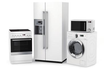
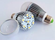
8 Applications WT1800E 8 Applications The WT1800E is a versatile instrument, unlocking precision power measurement capabilities for researchers, designers and engineers working on a wide variety of applications in energy efficiency and conservation and renewable energy. Whether it is for the manufacture of energy efficient devices and appliances, hybrid/electric vehicles or renewable energy technologies, the WT1800E is a universal meter for power electronic measurements and energy analysis. Key applications include: Plug-in Hybrid and Electric Vehicles Industrial equipment such as Inverters, Motors and Pumps Renewable energy technologies such as Solar and Wind power Office and Home appliances like Air conditioners and Refrigerators IT Data center equipment like Servers, Routers and Switches Battery charging and Portable devices Ballasts, LEDs & Fluorescent lighting Aircraft Power systems The following pages cover some typical applications for the WT1800E.
9 9 WT1800E Inverter and motor testing Inverter and motor testing Inverter Input Converter section Inverter section Drive circuit Motor Torque/ rotation sensor Load Convert AC to DC signals Modulate DC signal and convert to any AC signals *With three-phase input, power is measured with the three-phase three-wire system. *In this example, measurement is performed with the three-phase three-wire system (at 3V3A) to verify the (inter-phase) voltage and current of each phase. M indicates measurement points and input to the power analyzer. M indicates connecting the motor output to the motor signal input (/MTR) of the power analyzer Overview Electric and hybrid vehicles have many electrical and mechanical components and therefore an overall performance evaluation requires the efficiency measurement of both. With 6 channels of power inputs, flexible operation and a wide bandwidth, the WT1800E is ideal for efficiency tests between the input and output of inverters. An optional motor evaluation function enables the measurement of rotation speed and changes in torque. U1 R-phase Computed value Phase I2 current T-phase S-phase U2 Figure 1 Line voltage/phase current Delta computation I1 Line voltage R-phase Computed value U1 Phase voltage U3 Phase voltage voltage Phase T-phase U2 S-phase Figure 2 Delta-star conversion Obtain the line and phase voltages from the sums and differences of the instantaneous values of voltage and current in each element. Line voltages and phase currents that are not measured are computed in the three-phase three-wire system (Figure 1). Star-delta conversion: Line voltage is computed from the phase voltage using the three-phase four-wire system data. Delta-star conversion: Phase voltage is computed from the line voltage in the three-phase three-wire system (3V3A system) (Figure 2). The WT1800E advantages Wide bandwidth and High speed sampling The WT1800E is capable of 16-bit high resolution and 2 MHz sampling making it possible to measure faster signals with higher precision. Motor evaluation: Electrical angle/rotation/ direction Measure rotation speed, torque, and output (mechanical power) of motors from analog/pulse inputs of rotation or torque sensors. Harmonics and dual harmonics Simultaneously measure distortion factors like THD, fundamental and harmonic components. Harmonics up to the 500th order can be measured even at 50 ms data update rate. Users can also measure harmonics on two different sources simultaneously. Battery charge/discharge measurements In integrated measurement, the battery charge and discharge can be evaluated. Instantaneous positive and negative values captured at a high-speed sampling rate of 2 MS/s are integrated. Line filter to remove high frequency components In the power evaluation of inverter waveforms, measurement values are affected by high frequency components. A digital filter function makes it possible to remove unnecessary high frequency components superimposed on signals. The filter can be independently set for each input element. An analog filter for 1 MHz/ 300 khz, and a digital filter that can be set from 100 Hz to 100 khz in increments of 100 Hz are available as standard.
10 Efficiency of renewable energy systems WT1800E 10 Efficiency of renewable energy systems Solar cell module (outdoors) Mega solar system (outdoors) A Pyranometer (photovoltaic power generation) Vane anemometer (wind power generation) Power conditioner Boost AC/DC converter converter Power storage system 5 charge control Charge/ discharge 6 Power sold/bought Storage battery Plug-in HV, etc. Power Flow of Photovoltaic Power Generation 4 Load Reverse power flow Grid interconnection or smart grid (next-generation power network) indicates measurement points and input to the power analyzer. (A) indicates the connection of the sensor signals to the auxiliary input (/AUX) of the power analyzer. Overview Energy generated by photovoltaic cell modules and wind turbines is converted from DC to AC by a power conditioner. Minimizing losses in these conversions improves the efficiency in the overall energy system. The WT1800E provides up to 6 power inputs per unit for measuring voltage, current, power, and frequency (for AC) before and after each converter, as well as the converter and charging efficiencies. value Maximum power value * This is just an illustration. Actual measurements are affected by noise. Voltage value Typical voltage, current, and power measurements in MPPT control Measuring instantaneous peak power power value In photovoltaic power generation, an MPPT control varies the voltage to maximize energy harvested from the solar panel. The WT1800E is capable of measuring not only the voltage, current, and power but also the voltage, current, and power peak values for both plus (+) and minus ( ) sides. The WT1800E advantages Multiple channels and wide input range Evaluate Power conditioner efficiency using 6 input channels for simultaneous measurements from the inputs and outputs of boost converter, inverter, and storage battery. Direct input terminals (voltage range: 1.5 V to 1000 V and current range: 10 ma to 5 A or 1 A to 50 A) make it possible to perform high-precision measurements without using a current sensor. Harmonic distortion factor measurement Voltage fluctuations and harmonics flow into the power system due to reverse power flow. A harmonic measurement function enables measurement of harmonic components to compute and display total harmonic distortion factor (THD). Ripple factor and power loss measurements A user-defined function makes it possible to compute power loss, DC voltage and DC current ripple factors between the input and output. Up to 20 arithmetic expressions can be set. Display names for the arithmetic operations F1, F2, and so on can be freely changed. Typical arithmetic expressions 1. DC voltage ripple factor = [(Voltage peak value (+) Voltage peak value ( ))/2 DC voltage value (mean)] Power loss = Output power Input power Energy bought/sold and charged/discharged Measure the amount of power sold/bought in grid interconnection and of battery charge/discharge. Measure the amount of power sold/ bought in grid interconnections and in battery charge/discharges. The WT1800E enables the integration of current (q), apparent power (WS), reactive power (WQ), as well as the effective power integration in sold/bought power and charge/discharge modes. Furthermore, a user-defined function makes it possible to calculate the Average active power within the integration period.
11 11 WT1800E Efficiency of inverter-motor in electric vehicles Efficiency of inverter-motor in electric vehicles Input Batteries Booster Converter section Inverter section Drive circuit Motor Torque/ rotation sensor Load 1 2 Modulate and convert M DC to AC signals Overview The WT1800E supports power measurements on up to 6 input channels making it ideal for evaluating the efficiency between the input and output of an electric vehicle. A motor evaluation function (option) makes it possible to simultaneously monitor voltage, current, and power changes, as well as changes in rotation speed, torque and mechanical power. Typical repetitive high-speed charging and discharging signals Effective power (W+) Effective power (W ) Battery charge/discharge measurements Charge Discharge Charge current amount Ah (power amount Wh) and discharge current amount-ah (power amount-wh) can be integrated. In integrated measurement, the battery charge and discharge can be evaluated. Instantaneous positive and negative values captured at 2 MS/s high-speed sampling rate are integrated, and each of the total values is displayed. The WT1800E advantage Wide bandwidth and High speed sampling The WT1800E is capable of 16-bit high resolution and 2 MHz sampling making it possible to measure faster signals with greater precision. Harmonics and dual harmonics Motor testing is performed at various rotation speeds. The WT1800E supports a lower limit frequency of 0.1 Hz to enable measurement of harmonics at a very low motor rotation speed without using an external sampling clock. Motor evaluation: Electrical angle/rotation/direction Measure rotation speed, torque, and output (mechanical) power of motors from analog/pulse outputs of rotation or torque sensors. Individual null function: Offset correction for each input A common problem when testing inverter motors is the presence of ambient noise that can mean test values are non zero even before testing begins. The WT1800E s null function allows users to enable, disable or reset the offset values for voltage, current and motor input signals of each element separately. DA output and remote control Sometimes users may want to check changes in data, along with other measurement data (temperature, etc.) at the same time that communication data, such as voltage, current, power, and efficiency is required. A DA output function allows users to generate analog signals on up to 20 channels.
12 Specifications Specifications Inputs Input terminal type Voltage Plug-in terminal (safety terminal) Direct input: Large binding post External current sensor input: Insulated BNC connector Input type Voltage Floating input, resistive potential method Floating input, shunt input method Measurement range Voltage 1.5 V, 3 V, 6 V, 10 V, 15 V, 30 V, 60 V, 100 V, 150 V, 300 V, 600 V, 1000 V (for Crest factor CF3) 0.75 V, 1.5 V, 3 V, 5 V, 7.5 V, 15 V, 30 V, 50 V, 75 V, 150 V, 300 V, 500 V (for Crest factor CF6/CF6A) Direct input 50 A input element 1 A, 2 A, 5 A, 10 A, 20 A, 50 A (for Crest factor CF3) 500 ma, 1 A, 2.5 A, 5 A, 10 A, 25 A (for Crest factor CF6/CF6A) 5 A input element 10 ma, 20 ma, 50 ma, 100 ma, 200 ma, 500 ma, 1 A, 2 A, 5 A (for Crest factor CF3) 5 ma,10 ma, 25 ma, 50 ma, 100 ma, 250 ma, 500 ma, 1 A, 2.5 A (for Crest factor CF6/CF6A) External current sensor input 50 mv, 100 mv, 200 mv, 500 mv, 1 V, 2 V, 5 V, 10 V (for Crest factor CF3) 25 mv, 50 mv, 100 mv, 250 mv, 500 mv, 1 V, 2.5 V, 5 V (for Crest factor CF6/CF6A) Instrument loss Voltage Input resistance: Approximately 2 MΩ Input capacitance: Approximately 10 pf Direct input 50 A input element Approximately 2 mω + approximately 0.07 µh 5 A input element Approximately 100 mω + approximately 0.07 µh External current sensor input Approximately 1 MΩ Instantaneous maximum allowable input (20 ms or less) Voltage Peak voltage of 4 kv or RMS of 2 kv, whichever is lower Direct input 50 A input element Peak current of 450 A or RMS of 300 A, whichever is lower 5 A input element Peak current of 30 A or RMS of 15 A, whichever is lower External current sensor input Peak current is less than 10 times the range Instantaneous maximum allowable input (1 second or less) Voltage Peak voltage of 3 kv or RMS of 1.5 kv, whichever is lower Direct input 50 A input element Peak current of 150 A or RMS of 55 A, whichever is lower 5 A input element Peak current of 10 A or RMS of 7 A, whichever is lower External current sensor input Peak current is less than 10 times the range Continuous maximum allowable input Voltage Peak voltage of 2 kv or RMS of 1.1 kv, whichever is lower If the frequency of the input voltage exceeds 100 khz, (1200 f ) Vrms or less The letter f indicates the frequency of the input voltage and the unit is khz. Direct input 50 A input element Peak current of 150 A or RMS of 55 A, whichever is lower 5 A input element Peak current of 10 A or RMS of 7 A, whichever is lower External current sensor input Continuous maximum common mode voltage (50/60 Hz) Voltage input terminals: 1000 Vrms input terminals with /EX option without /EX option 1000 Vrms Peak current is less than 5 times the range 1000 Vrms (Maximum allowable voltage that can be measured) 600 Vrms (Rated voltage of EN standard) External current sensor input connector: 600 Vrms Important Safety Note: Do not touch the inside of the BNC connector of the External Sensor input for safety reasons. Rated voltage to ground Voltage input terminals: 1000 V input terminals with /EX option without /EX option 1000 V 1000 V (Maximum allowable voltage that can be measured) 600 V (Rated voltage of EN standard) External current sensor input connector: 600 V Important Safety Note: Do not touch the inside of the BNC connector of the External Sensor input for safety reasons. Influence from common voltage Apply 1000 Vrms for input terminal and case with the voltage input terminals shorted, the current input terminals open, and the external current sensor input terminals shorted. 50/60 Hz: ±0.01% of range or less Reference value up to 100 khz: ±[(maximum rated range) / (rated range) f % of range] or less. For external current sensor input, add ±{maximum rated range / rated range [ log (f 1000) 0.021]% of range}. However, 0.01% or more. Line filter Frequency filter A/D converter The unit of f is khz. The maximum rated range within the equation is 1000 V or 50 A or 5 A or 10 V. Select OFF, 100 Hz to 100 khz (in increments of 100 Hz), 300 khz, or 1 MHz Under condition of other than Auto data update interval Select OFF, 100 Hz, or 1 khz Under condition of Auto data update interval OFF, 100 Hz, 200 Hz, 400 Hz, 800 Hz, 1.6 khz, 3.2 khz, 6.4 khz, 12.8 khz and 25.6 khz Simultaneous voltage and current input conversion Resolution: 16-bit Conversion speed (sampling period): Approximately 500 ns. See harmonic measurement items for harmonic measurement. Range switching A range can be set for each input element WT1800E 12 Auto range functions Range up When the measured values of Urms and Irms exceed 110% of the range (exceed 220% when crest factor is set to CF6A) When the peak value of the input signal exceeds approximately 330% of the range (or approximately 660% for crest factor CF6/CF6A) Range down: When the following conditions are met, the range setting switches down. When the measured values of Urms and Irms fall to 30% or less of the range When the measured values of Urms and Irms fall to 105% or less of the lower range (range to which the range setting switches down) When the measured values of Upeak and Ipeak fall to 300% or less of the lower range (600% or less for crest factor CF6/CF6A) Display Display 8.4-inch color TFT LCD display Total number of pixels* 1024 (horizontal) 768 (vertical) dots *Up to approximately 0.002% of the pixels on the LCD may be defective. Display update rate Same as the data update rate. 1) The display update interval of numeric display alone is 200 ms to 500 ms (which varies depending on the number of display items) when the data update rate is 50 ms, 100 ms, and 200 ms. Display Items 2) The display update interval of display items other than numeric display (including custom displays) is approximately 1 s when the data update interval is 50 ms, 100 ms, 200 ms, and 500 ms. 3) If the measurement mode display is set to Normal Mode (Trg), measurement takes place from when a trigger is detected over the data update interval. The following amount of time is required for the WT1800E to compute the measured data, process it for displaying, and so on, and become ready for the next trigger. When the data update interval is 50 ms to 500 ms: Approximately 1 s When the data update interval is 1 s to 5 s: Data update interval ms In this case, storage, communication output, and D/A output operate in sync with the triggers. If the measurement mode display is set to Normal Mode, storage, communication output, and D/A output operate in sync with the data update interval. 4) The display update interval is more than 200 ms in the case of numerical value indication when update interval is set to Auto. In addition, the interval is more than 1 s in case of other display indications including Custom screen excepting the numerical value. Calculation Functions Measurement Function Single-phase 3-wire 3-phase 3-wire 3-phase 3-wire (3-voltage 3-current measurement) Voltage U [V] (U1+U2)/2 (U1+U2+U3)/3 I [A] ( I1+ I 2)/2 ( I1+ I 2+ I 3)/3 3-phase 4-wire Active power P [W] P1+P2 P1+P2+P3 Apparent Power S [VA] Reactive Power Q [var] TYPE1 S1+S2 3 (S1+S2) TYPE2 2 TYPE3 P 2 + Q 2 3 (S1+S2+S3) 3 S1+S2+S3 TYPE1 Q1+Q2 Q1+Q2+Q3 TYPE2 S 2 P 2 TYPE3 Q1+Q2 Q1+Q2+Q3 Corrected Power Pc [W] Pc1+Pc2 Pc1+Pc2+Pc3 Integrated Power WP [Wh] WP1+WP2 Integrated Power (Positive) WP+ [Wh] Integrated Power (Negative) WP [Wh] WP+1+WP+2 When WPTYPE is set to CHARGE/DISCHARGE WP1+WP2+WP3 WP+1+WP+2+WP+3 When WPTYPE is set to SOLD/BOUGHT Whenever data is updated, only the positive value of active power WP is added This item is not calculated when Data update interval is set to Auto WP 1+WP 2 When WPTYPE is set to CHARGE/DISCHARGE WP 1+WP 2+WP 3 When WPTYPE is set to SOLD/BOUGHT Whenever data is updated, only the negative value of active power WP is adde This item is not calculated when Data update interval is set to Auto Integrated q [Ah] q1+q2 q1+q2+q3 Integrated (Positive) q+ [Ah] Integrated (Negative) q [Ah] Integrated reactive Power WQ [varh] Integrated apparent Power WS [VAh] Power Factor Phase angle Ø [ ] q+1+q+2 q 1+q 2 1 N N n=1 Q (n) Time q+1+q+2+q+3 q 1+q 2+q 3 Q (n) indicates the function of the n th reactive power, N indicates the number of data updates, and the unit of Time is h This item is not calculated when Data update interval is set to Auto 1 N N n=1 S (n) Time S (n) indicates the function of the n th apparent power, N indicates the number of data updates, and the unit of Time is h This item is not calculated when Data update interval is set to Auto P /S COS 1 (P /S ) Note 1) The instrument s apparent power (S), reactive power (Q), power factor (λ), and phase difference (Ø) are calculated using measured values of voltage, current, and active power. (However, reactive power is calculated directly from sampled data when TYPE3 is selected.) Therefore, when distorted waveforms are input, these values may be different from those of other measuring instruments based on different measuring principals.
13 WT1800E 13 Specifications Note 2) The value of Q for each phase in the Q calculation is calculated with a preceding minus sign ( ) when the current input leads the voltage input, and a plus sign when it lags the voltage input, so the value of Q may be negative. Numerical Display [Measurement functions obtained for each input element] Voltage (V) Urms: True RMS value, Umn: Rectified mean value calibrated to the RMS value, Udc: Simple mean value, Urmn: Rectified mean value, Uac: AC component (A) Active power (W) Urms: True RMS value, Imn: Rectified mean value calibrated to the RMS value, Idc: Simple mean value, Irmn: Rectified mean value, Iac: AC component P Apparent power (VA) S Reactive power (var) Q Power factor Phase angle ( ) Frequency (Hz) λ Ø f U (FreqU): Voltage frequency, fl (Freql): frequency Maximum and minimum voltage values (V) U+peak: Maximum voltage value, U peak: Minimum voltage value Maximum and minimum current values (A) I+peak: Maximum current value, I peak: Minimum current value Maximum and minimum power values (W) P+peak: Maximum power value, P peak: Minimum power value Crest factor C f U: Voltage crest factor, CfI: crest factor Corrected power (W) Pc Applicable standards IEC76-1 (1976), IEC76-1 (1993) Integration Time: Integration time WP: Sum of the amount of both positive and negative power WP+: Sum of positive P (amount of power consumed) WP : Sum of negative P (amount of power returned to the grid) q: Sum of the amount of both positive and negative current q+: Sum of positive I (amount of current) q : Sum of negative I (amount of current) WS*: Amount of apparent power WQ*: Amount of reactive power However, the amount of current is integrated by selecting any one of Irms, Imn, Idc, Iac, and Irmn depending on the setting of the current mode. *Excepting when data update interval is set to Auto. [ Measurement function ( function) obtained for each connected unit ( A, B, C)] Voltage (V) Urms : True RMS value, Umn : Rectified mean value calibrated to the RMS value, Udc : Simple mean value, Urmn: Rectified mean value, Uac : AC component (A) Active power (W) Irms : True RMS value, Imn : Rectified mean value calibrated to the RMS value, Idc : Simple mean value, Irmn : Rectified mean value, Iac : AC component P Apparent power (VA) S Reactive power (var) Q Power factor λ Corrected power (W) Pc Applicable standards IEC76-1 (1976), IEC76-1 (1993) Integration Time : Integration time WP : Sum of the amount of both positive and negative power WP+ : Sum of positive P (amount of power consumed) WP : Sum of negative P (amount of power returned to the grid) q : Sum of the amount of both positive and negative current q+ : Sum of positive I (amount of current) q : Sum of negative I (amount of current) WS : Integration of S WQ : Integration of Q Harmonic Measurement (Option) [Measurement function obtained for each input element] Voltage (V) U (k): RMS value of the harmonic voltage of order k *1, U: Voltage RMS value (Total value *2 ) (A) I (k): RMS value of the harmonic current of order k, I: RMS value (Total value *2 ) Active power (W) P (k): Active power of the harmonic of order k, P: Active power (Total value *2 ) Apparent power (VA) S (k): Apparent power of the harmonic of order k, S: Total apparent power (Total value *2 ) Reactive power (var) Q (k): Reactive power of the harmonic of order k, Q: Total reactive power (Total value *2 ) Power factor λ (k): Power factor of the harmonic of order k, λ: Total power factor (Total value *2 ) Phase angle ( ) Ø (k): Phase angle between the harmonic voltage and current of order k, Ø: Total phase angle Ø U (k): Phase angle of each harmonic voltage U (k) relative to the fundamental wave U (1) Ø I (k): Phase angle of each harmonic current I (k) relative to the fundamental wave I (1) Impedance of the load circuit (Ω) Z (k): Impedance of the load circuit for the harmonic of order k Resistance and reactance of the load circuit (Ω) Rs (k): Resistance of the load circuit to the harmonic of order k when the resistance R, the inductance L, and the capacitor C are connected in series Xs (k): Reactance of the load circuit to the harmonic of order k when the resistance R, the inductance L, and the capacitor C are connected in series Rp (k): Resistance of the load circuit to the harmonic of order k when the resistance R, the inductance L, and the capacitor C are connected in parallel Xp (k): Reactance of the load circuit to the harmonic of order k when the resistance R, the inductance L, and the capacitor C are connected in parallel Harmonic content [%] Total harmonic distortion [%] Telephone harmonic factor Telephone influence factor Harmonic voltage factor *4 Harmonic current factor *4 K-factor Uhdf (k): Ratio of the harmonic voltage U (k) to U (1) or U Ihdf (k): Ratio of the harmonic current I (k) to I (1) or I Phdf (k): Ratio of the active harmonic power P (k) to P (1) or P Uthd: Ratio of the total harmonic *3 voltage to U (1) or U Ithd: Ratio of the total harmonic *3 current to I (1) or I Pthd: Ratio of the total harmonic *3 active power to P (1) or P Uthf: Voltage telephone harmonic factor, Ithf: telephone harmonic factor Applicable standard: IEC34-1 (1996) Utif: Voltage telephone influence factor, Itif: telephone influence factor Applicable standard: IEEE Std 100 (1996) hvf: harmonic voltage factor hcf: harmonic current factor Ratio of the sum of the squares of weighted harmonic components to the sum of the squares of the orders of harmonic current *1: Order k is an integer in the range from 0 to the upper limit value for the measured order. The 0th order is a DC current component (dc). The upper limit value for the measured order is automatically determined up to the 500th order depending on the frequency of the PLL source. *2: The total value is calculated by obtaining the fundamental wave (the 1st order) and all harmonic components (from the 2nd order to the upper limit value for the measured order). Also, the DC component (dc) can be added to the equation. *3: The total harmonic is calculated by obtaining the total harmonic component (from the 2nd order to the upper limit value for the measured order) *4: The equations may vary depending on the definitions in the standards, etc. Check the standards for details. [Measurement function indicating the phase difference of the fundamental wave between the voltage and current between input elements] This is a measurement function indicating the phase angle of the fundamental wave U (1) or I (1) of another element to the fundamental wave U (1) of the element with the smallest number among input elements assigned to the connected unit. The following table shows measurement functions for the connected unit with a combination of the elements 1, 2, and 3. Phase angle U1 U2 ( ) ØU1 U2: Phase angle of the fundamental wave (U2 (1)) of the voltage of the element 2 to the fundamental wave (U1 (1)) of the voltage of the element 1 Phase angle U1 U3 ( ) ØU1 U3: Phase angle of the fundamental wave (U3 (1)) of the voltage of the element 3 to U1 (1) Phase angle U1 I1 ( ) ØU1 I1: Phase angle of the fundamental wave ( I1 (1)) of the current of the element 1 to U1 (1) Phase angle U2 I2 ( ) ØU2 I2: Phase angle of the fundamental wave ( I 2 (1)) of the current of the element 2 to U2 (1) Phase angle U3 I3 ( ) ØU3 I3: Phase angle of the fundamental wave ( I 3 (1)) of the current of the element 3 to U3 (1) EaU1 to EaU6 ( ), EaI1 to EaI6 ( ) Phase angle Ø of the fundamental waves of U1 to I6 based on the rise of the Z terminal input in the motor evaluation function (option). N is the set value for the number of poles in the motor evaluation function. [Measurement function ( function) obtained for each connected unit ( A, B, C)] Voltage (V) U (1): RMS of the harmonic voltage of order 1, U : RMS of the voltage (Total value*) (A) I (1): RMS of the harmonic current of order 1, I : RMS of the current (Total value*) Active power (W) P (1): Harmonic active power of order 1, P : Total active power (Total value*) Apparent power (VA) S (1): Harmonic apparent power of order 1, S : Total apparent power (Total value*) Reactive power (var) Q (1): Harmonic reactive power of order 1, Q : Total reactive power (Total value*) Power factor λ (1): Harmonic power factor of order 1, λ : Total power factor (Total value*) * The total value is calculated by obtaining the fundamental wave (the 1st order ) and all harmonic components (from the 2nd order to the upper limit value for the measured order). Also, the DC component (dc) can be added to the equation. Delta Calculation Voltage (V) difference ΔU1: Differential voltage between U1 and U2 determined by computation 3P3W->3V3A DELTA->STAR STAR->DELTA ΔU1: Line voltage that is not measured but can be computed for a three-phase, three-wire system ΔU1, ΔU2, ΔU3: Phase voltage that can be computed by a threephase, three-wire (3V3A) system ΔU = (ΔU1 + ΔU2 + ΔU3)/3 ΔU1, ΔU2, ΔU3: Line voltage that can be computed for a threephase, four-wire system ΔU = (ΔU1 + ΔU2 + ΔU3)/3
14 Specifications WT1800E 14 (A) difference ΔI1: Differential current between I1 and I2 determined by computation 3P3W->3V3A ΔI: Phase current that is not measured DELTA->STAR ΔI: Neutral line current STAR->DELTA ΔI: Neutral line current Power (W) difference 3P3W->3V3A DELTA->STAR STAR->DELTA ΔP1, ΔP2, ΔP3: Phase power determined by computation for a threephase, three-line (3V3A) system ΔP = ΔP1 + ΔP2 + ΔP3 Waveform/Trend Waveform display Displays the waveforms of the voltage and current from elements 1 through 6, torque, speed, AUX1, and AUX2. Trend display Displays trends in numerical data of the measurement functions in a sequential line graph. Number of measurement channels: Up to 16 parameters Bar Graph/ Vector (/G5, /G6 Option) Bar graph display Displays the size of each harmonic in a bar graph. Vector display Displays the vector of the phase difference in the fundamental waves of voltage and current. Voltage and : (six-month) Conditions Temperature: 23±5 C, Humidity: 30 to 75%RH, Input waveform: Sine wave, Power factor (λ): 1, Common mode voltage: 0 V, Crest factor: CF3, Line filter: OFF Frequency filter: 1 khz or less when ON, after warm-up. After zero level compensation or range value changed while wired. The unit of f within the accuracy equation is khz. Voltage Frequency ±(Measurement reading error + Setting range error) DC ±(0.05% of reading % of range) 0.1 Hz f < 10 Hz ±(0.03% of reading % of range) 10 Hz f < 45 Hz ±(0.03% of reading % of range) 45 Hz f 66 Hz ±(0.03% of reading % of range)* 66 Hz < f 1 khz ±(0.1% of reading + 0.1% of range) 1 khz < f 50 khz ±(0.3% of reading + 0.1% of range) 50 khz < f 100 khz ±(0.6% of reading + 0.2% of range) 100 khz < f 500 khz ±[(0.006 f )% of reading + 0.5% of range] 500 khz < f 1 MHz ±[(0.022 f 8)% of reading + 1% of range] Frequency bandwidth 5 MHz ( 3 db, typical) *Add 0.02% of reading under condition of the 1000 V range. Frequency DC ±(Measurement reading error + Setting range error) ±(0.05% of reading % of range) 0.1 Hz f < 10 Hz ±(0.03% of reading % of range) 10 Hz f < 45 Hz ±[(0.03% of reading % of range) + (2 µa*)] 45 Hz f 66Hz ±[(0.03% of reading % of range) + (2 µa*)] 66 Hz < f 1 khz ±(0.1% of reading + 0.1% of range) Direct input of the 50 A input element ±(0.2% of reading + 0.1% of range) 1 khz < f 50 khz ±(0.3% of reading + 0.1% of range) 50 mv, 100 mv, 200 mv range of the external current sensor input ±(0.5% of reading + 0.1% of range) Direct input of the 50 A input element ±[(0.1 f + 0.2)% of reading + 0.1% of range] 50 khz < f 100 khz ±(0.6% of reading + 0.2% of range) Direct input of the 50 A input element ±[(0.1 f + 0.2)% of reading + 0.1% of range] 100 khz < f 200 khz ±[(0.006 f )% of reading + 0.5% of range] Direct input of the 50 A input element ±[(0.05 f + 5)% of reading + 0.5% of range] 200 khz < f 500 khz ±[(0.006 f )% of reading + 0.5% of range] Direct input of the 50 A input element: It does not define accuracy. 500 khz < f 1 MHz ±[(0.022 f 8)% of reading + 1% of range] Direct input of the 50 A input element: It does not define accuracy. Frequency bandwidth *Not added under the External current sensor input setting 5 MHz ( 3 db, typical): 5 A input element, External current sensor input of the 50 A input element Power: (six-month) Conditions Same as the accuracy of the voltage and current Frequency ±(Reading error + Measurement range error) DC ±(0.05% of reading % of range) 0.1 Hz f < 10 Hz ±(0.08% of reading + 0.1% of range) 10 Hz f < 45 Hz ±[(0.08% of reading + 0.1% of range) + (2 µa U)*] 45 Hz f 66 Hz ±[(0.05% of reading % of range) + (2 µa U)*] 66 Hz < f 1 khz ±(0.2% of reading + 0.1% of range) 1 khz < f 50 khz ±(0.3% of reading + 0.2% of range) 50 mv, 100 mv, 200 mv range of the external current sensor input ±(0.5% of reading + 0.2% of range) Direct input of the 50 A input element ±[(0.1 f + 0.2)% of reading + 0.2% of range] 50 khz < f 100 khz ±(0.7% of reading + 0.3% of range) Direct input of the 50 A input element ±[(0.3 f 9.5)% of reading + 0.3% of range] 100 khz < f 200 khz ±[(0.008 f )% of reading + 1% of range] Direct input of the 50 A input element ±[(0.09 f + 11)% of reading + 1% of range] 200 khz < f 500 khz ±[(0.008 f )% of reading + 1% of range] Direct input of the 50 A input element: It does not define accuracy. 500 khz < f 1 MHz ±[(0.048 f 20)% of reading + 2% of range] Direct input of the 50 A input element: It does not define accuracy. *Not added under the External current sensor input setting Add the following value to the above accuracy for the external current sensor range. DC accuracy: ±50 µv Power DC accuracy: ±[(50 µv/external current sensor range rating) 100% of range] Add the following value to the above accuracy for the direct current input range. 50 A input element DC accuracy: ±1.5 ma Power DC accuracy: ±[(1 ma/direct current input range rating) 100% of range] 5 A input element DC accuracy: ±15 µa Power DC accuracy: ±[(10 µa/direct current input range rating) 100% of range] of the waveform display data, Upeak and Ipeak Add the following value to the above accuracy (reference value). The effective input range is within ±300% of range (within ±600% for Crest factor CF6/CF6A) Voltage input: ± ( ) % of range range Direct current input 50 A input element: ±( 3 1 % of range + 10 range ma) External current sensor input 5 A input element: ± ( m )% of range range 50 mv to 200 mv range: ± ( )% of range range ( 500 mv to 10 V range: ± ) % of range range Influence from a temperature change after zero level compensation or range change Add the following value to the above accuracy. Voltage DC accuracy; ±0.02% of range/ C DC accuracy of the direct current input 50 A input element: ±1 ma/ C 5 A input element: ±10 µa/ C DC accuracy of the external current sensor input: ±50 µv/ C DC power accuracy: Influence from the voltage Influence from the current Influence from the self-heating caused by voltage input Add the following value to the voltage and power accuracy. AC input signal: ±( U 2 % of reading) DC input signal: ±( U 2 % of reading U 2 % of range) U is the voltage reading (V). The influence from the self-heating continues until the temperature of the input resistor decreases, even if the voltage input changes to a small value. Influence from the self-heating caused by current input Add the following value to the current and power accuracy of the 50 A element. AC input signal: ± I 2 % of reading DC input signal: ±( I 2 % of reading I 2 ma) Add the following value to the current and power accuracy of the 5 A element. AC input signal: ±0.006 I 2 % of reading DC input signal: ±(0.006 I 2 % of reading I 2 ma) I is the current reading (A). The influence from the self-heating continues until the temperature of the shunt resistor decreases, even if the current input changes to a small value. Range of guaranteed accuracy by frequency, voltage, and current All accuracies between 0.1 Hz to 10 Hz are reference values. If the voltage exceeds 750 V at 30 khz to 100 khz, the voltage and power values are reference values. If the current exceeds 20 A at DC, 10 Hz to 45 Hz, or 400 Hz to 100 khz, the current and power accuracies are reference values. for Crest factor CF6/CF6A Same as the range accuracy of Crest factor CF3 for twice the range. Influence of power factor (λ) When λ = 0 ±(Apparent power reading 0.07% for the range) of 45 Hz to 66 Hz For frequencies other than the above (Design values): 5 A input element and the external sensor input: ±[Apparent power reading ( f )%] Direct input of the 50 A input element: ±[Apparent power reading ( f )%] When 0 < λ < 1 ±Power reading {(Power reading error %) + (Power range error %) (Power range/apparent power reading) + [tan Ø (Influence % when λ = 0)]} Ø is the phase angle between the voltage and current. Influence % when λ = 0 will be changed according to input frequency f of above expression.
15 WT1800E 15 Specifications Influence of line filter When the cutoff frequency (fc) is 100 Hz to 100 khz Voltage/current Power Up to fc 2 Hz: Add ± f fc Applies to frequency less than or equal to 30 khz Up to fc 2 Hz: Add ± f fc Applies to frequency less than or equal to 30 khz When the cutoff frequency (fc) is 300 khz and 1 MHz Voltage/current Up to (fc/10) Hz: Add ±(20 f/fc)% of reading Power Up to (fc/10) Hz: Add ±(40 f/fc)% of reading f % of reading 300 k f % of reading 300 k Lead/lag phase detection [D (LEAD)/G (LAG) of the phase angle] The phase lead and lag can be detected correctly when the voltage and current input signals are as follows. Sine wave 50% or more of the measurement range (100% or more for crest factor CF6/CF6A) Frequency: 20 Hz to 10 khz Phase angle: ±(5 to 175 ) Symbols for the reactive power Q calculation The symbols shows the lead/lag of each element, and indicates leading. Temperature coefficient ±0.03% of reading/ C at 5 to 18 C or 28 to 40 C Effective input range Udc and Idc: 0 to ±110% of the measurement range Urms and Irms: 1 to 110% of the measurement range Umn and Imn: 10 to 110% of the measurement range Urmn and Irmn: 10 to 110% of the measurement range Power (DC measurement): 0 to ±110% (AC measurement): ±110% of the power range when the voltage and current range is 1 to 110%. However, the synchronization source level shall meet the input signal level of frequency measurement. Each of the lower and higher limits are doubled for Crest factor CF6/CF6A. Maximum display value 140% of the voltage and current range rating When Crest factor is set to CF6A, 280% of the voltage and current range rating Minimum display value Displays the following values relative to the measurement range. Urms, Uac, Irms, Iac: Up to 0.3% (up to 0.6% for Crest factor CF6/CF6A) Umn, Urmn, Imn, Irmn: Up to 2% (up to 4% for Crest factor CF6/CF6A) When input level is lower than above, the display shows zero if zero-suppress setting is ON, otherwise measured value will be shown. integration value q depends on the current value as well. Measurement lower limit frequency Data update rate 50 ms 100 ms 200 ms 500 ms Measurement lower limit frequency 45 Hz 25 Hz 12.5 Hz 5 Hz Data update rate 1 s 2 s 5 s 10 s 20 s Auto Measurement lower limit frequency 2.5 Hz 1.25 Hz 0.5 Hz 0.2 Hz 0.1 Hz 0.1 Hz of apparent power S ±( Voltage accuracy + accuracy) of reactive power Q ±[ of apparent power + ( λ 2 1 λ 2 ) 100% of range] of power factor λ ±{( λ λ /1.0002) + cosø cos [Ø+ sin 1 (influence of power factor of power when λ = 0%/100)] } ±1 digit when voltage and current is at rated input of the measurement range. Ø is the phase difference of voltage and current. of phase angle Ø ±( Ø {cos 1 ( λ /1.0002) + sin 1 [(influence of power factor of power when λ = 0%)/100]}) deg ±1 digit, when voltage and current is at the rated input of the measurement range. One-year accuracy Multiply the reading error of the six-month accuracy by a factor of 1.5 Functions Measurement Functions and Conditions Crest factor: 300 (relative to the minimum valid input) CF3: 3 (relative to the rated value of the mesurement range) CF6/CF6A: 6 (relative to the rated value of the measurement range) Measurement period Interval for determining the measurement function and performing calculations. The measurement period is set by the zero crossing of the reference signal (synchronization source) excluding watt hour WP and ampere hour q during DC mode. Timing of Data update is different (minimum time resolution is 50 ms) among elements with different reference signals (synch sources) setting when the Data update interval is set to Auto. Timeout period can be selected from 1 s, 5 s, 10 s or 20 s. And full period of timeout becomes actual measurement period when synchronization source signal does not input any cycles during the timeout period. Harmonic display The measurement period is from the beginning of the data update interval to 1024 or 8192 points at the harmonic sampling frequency. Measurement period detection method Analog signal zero cross detection method when Data update interval is set to other than Auto. In case of sampling data level detection method when Data update interval is set to Auto, data level can be set arbitrarily. Wiring 1P2W (single-phase, two-wire), 1P3W (single-phase, 3-wire), 3P3W (3-phase, 3-wire), 3P4W (3-phase, 4-wire), 3P3W (3V3A) (3-phase, 3-wire, 3-volt/3-amp measurement) However, the number of available wiring systems varies depending on the number of installed input elements. Scaling When inputting output from external current sensors, VT, or CT, set the current sensor conversion ratio, VT ratio, CT ratio, and power coefficient in the range from to CT ratio can be set automatically by selecting a model name of CT series. sensor conversion ratio can be set automatically by selecting a model name of dedicated shunt resistors. Averaging The average calculations below are performed on the normal measurement parameters of voltage U, current I, power P, apparent power S, and reactive power Q. Power factor λ and phase angle are determined by calculating the average of P and S. Select exponential or moving averaging. Exponential average: Select an attenuation constant from 2 through 64. Moving average: Select the number of averages from 8 through 64. Harmonic measurement Only exponential averaging is available. Data update interval Select 50 ms, 100 ms, 200 ms, 500 ms, 1 s, 2 s, 5 s, 10 s, 20 s, or Auto. Period detection method is different depending on update interval. 50 ms, 100 ms, 200 ms, 500 ms, 1 s, 2 s, 5 s, 10 s, 20 s : Analog signal zero cross detection method Auto: Sampling data level detection method Response time At maximum, twice the data update interval (only during numerical display) When Data update interval is set to Auto, response time is signal cycle period and added 50 ms. Hold Single Holds the data display. Executes a single measurement during measurement hold. When the Data update interval is set to Auto, single mesurement cannot be excuted. Zero level compensation/null Compensates the zero level. Null compensation range: ±10% of range Null can be set individually for each of the following input signals. Voltage and current of each input element Rotation speed and torque AUX1 and AUX2 Frequency Measurement Number of measurement The frequencies of voltages and currents for all input elements can be measured. Measurement method Reciprocal method Measurement range Data update rate Measuring range 50 ms 45 Hz f 1 MHz 100 ms 25 Hz f 1 MHz 200 ms 12.5 Hz f 500 khz 500 ms 5 Hz f 200 khz 1 s 2.5 Hz f 100 khz 2 s 1.25 Hz f 50 khz 5 s 0.5 Hz f 20 khz 10 s 0.25 Hz f 10 khz 20 s 0.15 Hz f 5 khz Auto 0.1 Hz < f 500 khz ±0.06% of reading ±0.1 mhz When the input signal level is 30% or more of the measurement range (60% or more for Crest factor CF6/CF6A). However: The input signal is 50% or more of the range. The frequency is smaller or equal to 2 times of above lower frequency 10 ma range setting of 5 A input element 1 A range setting of 50 A input element When the Data update interval is set to other than Auto, the 100 Hz frequency filter is ON at 0.15 Hz to 100 Hz, and the 1 khz frequency filter is ON at 100 Hz to 1 khz. When the Data update interval is set to Auto, 100 Hz cutoff frequency filter is set to ON for 0.1 Hz to 100 Hz, and 1.6 khz cutoff frequency filter is set to ON for 100 Hz to 1 khz. Display resolution Minimum frequency resolution Hz Frequency measurement filter (the Data update interval is set to other than Auto) Select from OFF, 100 Hz or 1 khz Integration Mode (the Data update interval is set to Auto) Select from OFF, 100 Hz, 200 Hz, 400 Hz, 800 Hz, 1.6 khz, 3.2 khz, 6.4 khz, 12.8 khz or 25.6 khz. Select a mode from Manual, Standard, Continuous (repeat), Real Time Control Standard, and Real Time Control Continuous (Repeat). * When Data update interval is set to Auto, integration will executes in Manual mode and timer mode only. Other Integration modes like Continuous, Real Time Control Standard and Real Time Control Continuous are not supported. Integration timer Integration can be stopped automatically using the timer setting. 0000h00m00s to 10000h00m00s
Highest accuracy & precision. WT3000E Series Precision Power Analyzers ±0.04% WT3000E. Total. Bulletin WT3000E-01EN ±0.10% ±0.15% ±0.
 Highest accuracy & precision Total ±0.04% Series Precision Power Analyzers ±0.10% WT1800E ±0.15% WT300E Series ±0.20% Bulletin -01EN WT500 PX8000 Devices such as solar inverters are already working at
The world s best seller. WT300E Series Digital Power Meter. Bulletin WT300E-01EN
 The world s best seller WT300E Series Digital Power Meter Bulletin WT300E-01EN The WT300E series is the enhanced version of Yokogawa s 5 th generation of compact power meters. The world s best-selling
WT to 40 A. 15 to 1000 V 0.2% DC 0.5 Hz to 100 khz. Power Analyzer. Power Analyzer WT500
 Power Analyzer Power Analyzer Simultaneous measurement of voltage, current, power, and harmonics High-speed data updating (00 ms) Display of numerical values, waveforms and trends Measurement of bought
APPLICATIONS. Oscilloscope Display. Harmonic Measurement. High Precision Measurement up to 0.1% Power Supplies Tests Motor Tests
 YOUR POWER TESTING SOLUTION IT9100 Power Meter Oscilloscope Display Harmonic Measurement High Precision Measurement up to 0.1% IT9100 Power Meter APPLICATIONS Power Supplies Tests Motor Tests Household
Next generation in precision. WT5000 Precision Power Analyzers. Bulletin WT EN
 Next generation in precision Precision Power Analyzers Bulletin -01EN As renewable energy, electric vehicles and energy efficient technologies gain wider adoption, the need for reliability in testing efficiency,
Input Elements Max. 6 Current Measurement 100 µ A to 55 A Fast data Capturing 5 ms Response *Max.1ms (When External Sync ON)
") High Performance Analyzer High Performance Analyzer Broad Ranging Measurements with One Unit Basic ±0.1% DC ±0.05% / Bandwidth 5 MHz *1 (-3 db, Typical) Sampling Rate 2 MS/s (16-bit) Input Elements Max.
High Performance Analyzer High Performance Analyzer Broad Ranging Measurements with One Unit Basic ±0.1% DC ±0.05% / Bandwidth 5 MHz *1 (-3 db, Typical) Sampling Rate 2 MS/s (16-bit) Input Elements Max.
APPLICATIONS. Oscilloscope Display. Harmonic Measurement. High Precision Measurement up to 0.1% Input Range 1000Vrms/50Arms
 YOUR POWER TESTING SOLUTION IT9100 Power Meter Oscilloscope Display Harmonic Measurement High Precision Measurement up to 0.1% Input Range 1000Vrms/50Arms IT9100 Power Meter APPLICATIONS Power Supplies
Technical Specifications for Portable 3-Ø Power Analyzer
 Technical Specifications for Portable 3-Ø Power Analyzer SCOPE: This specification covers the general specifications of 3-phase power analyzer that can be used to measure the no load and full load losses
Digital Sampling Power Meter. Digital Power Meter and Power Analyzer WT210/WT230 WT1600 WT2010/WT2030 PZ4000
 Total Solution Digital Sampling Power Meter Digital Power Meter and Power Analyzer WTSERIES & PZ WT0/WT0 WT600 WT00/WT00 Information on the features and functions of Yokogawa's WT series & PZ, accessories,
Accurately measure devices up to 1000 V/65 A AC/DC with direct input
 POWER METER PW3336, PW3337 High-precision, 3-channel power meter with built-in harmonic measurement Accurately measure devices up to 1000 V/65 A AC/DC with direct input The PW3336 (2-channel) and PW3337
Specifications. WT5000 Precision Power Analyzers. Bulletin WT EN
 WT5000 Precision Power Analyzers Bulletin WT5000-02EN WT5000 WT5000 Precision Power Analyzers 2 Signal Input Section Power Measurement Element Number of elements 7 Plug-in input unit Installable input
WT5000 Precision Power Analyzer
 WT5000 Precision Power Analyzer Features Guide 1st Edition List of Manuals Thank you for purchasing the WT5000 Precision Power Analyzer. This manual contains useful information about the features of this
5MS/s. Power Analyzer
 Established 98 Advanced Test Equipment Rentals www.atecorp.com 800-404-ATEC (83) 5MS/s Power Analyzer Wide bandwidth (DC, up to MHz) Accurately capturing of input waveforms using high-speed (maximum 5
High-accuracy measurement of standby to operating power
 POWER METER PW3335 Power Measuring Instruments Single-Phase AC/DC Power Meter High- of standby to operating power Wide measurable range : 10 μa to 30 A, 60 mv to 1000 V Basic for voltage, current and power
High-accuracy measurement of standby to operating power
 POWER METER PW3335 Single-Phase AC/DC Power Meter High- of standby to operating power Wide measurable range : 10 μa to 30 A, 60 mv to 1000 V Basic for voltage, current and power : ±0.1%* Frequency bandwidth
Fluke Norma 4000/5000
 Fluke Norma 4000/5000 High Precision Power Analyzers Reliable, highly accurate measurements for the test & development of power electronics Technical Data Compact Fluke Norma Series power analyzers include
WT210/WT at rated. 5 ma range. input Low current (WT210) DC 0.5 Hz. to100 khz. Digital Power Meters ±0.2% WT210/WT230 Digital Power Meters
 DC 0.5 Hz. to100 khz. Digital Power Meters ±0.2% WT210/WT230 Digital Power Meters") WT2/WT23 Digital Power Meters WT2/WT23 Digital Power Meters Digital Sampling Power Meters with Superior Cost Performance Low power measurement (IEC623) Harmonic measurement Compact design (half-rack size)
WT2/WT23 Digital Power Meters WT2/WT23 Digital Power Meters Digital Sampling Power Meters with Superior Cost Performance Low power measurement (IEC623) Harmonic measurement Compact design (half-rack size)
ENERGY SAVING TOOLS. Digital Sampling Power Meters with Superior Cost Performance. Digital Power Meters
 Established 98 Advanced Test Equipment Rentals www.atecorp.com 8-44-ATEC (2832) ENERGY SAVING TOOLS Digital Sampling Power Meters with Superior Cost Performance Digital Power Meters WT2/WT23 Basic power
Precision Power Analyzer
 Precision Analyzer WT000 WT000 High-end Precision Analyzer Meter with top precision* Basic : 0.02% of reading New Options Available Store Function (Comes standard) USB Port for Peripherals (Optional) USB
The PW3336 (2-channel) and PW3337 (3-channel) can measure DC and a variety of power connections ranging from single-phase 2-wire to 3-phase 4-wire*.
 and PW3337 (3-channel) can measure DC and a variety of power connections ranging from single-phase 2-wire to 3-phase 4-wire*.") POWER METER PW3336/PW3337 Power Measuring Instruments High-precision, 3-channel power meter with built-in harmonic measurement Accurately measure devices up to 1000 V/65 A AC/DC with direct input The PW3336
POWER METER PW3336/PW3337 Power Measuring Instruments High-precision, 3-channel power meter with built-in harmonic measurement Accurately measure devices up to 1000 V/65 A AC/DC with direct input The PW3336
Fluke Norma 4000/5000
 Fluke Norma 4000/5000 High Precision Power Analyzers Reliable, highly accurate measurements for the test & development of power electronics Technical Data Compact Fluke Norma Series power analyzers include
5500A. Multi-Product Calibrator. Extended Specifications 2005
 5500A Multi-Product Calibrator Extended Specifications 2005 5500A Specifications The following paragraphs detail specifications for the 5500A Calibrator. The specifications are valid after allowing a warm-up
3331, 3332 POWER HiTESTER
 99 Washington Street Melrose, MA 02176 Fax 781-665-0780 TestEquipmentDepot.com An Energy Saving Support Tool 2002 3331, 3332 POWER HiTESTER Power measuring instruments 3332: Single-phase, 2-wire type that
Broad Ranges Power Measurement with One Unit. Basic Power Accuracy ±0.1% DC Power Accuracy ±0.05% Voltage/Current Bandwidth 5 MHz *1 (-3 db, Typical)
") High Performance Power Analyzer WT1800 WT1800 High Performance Power Analyzer Broad Ranges Power Measurement with One Unit Basic Power ±0.1% DC Power ±0.05% Voltage/ Bandwidth 5 MHz *1 (-3 db, Typical)
High Performance Power Analyzer WT1800 WT1800 High Performance Power Analyzer Broad Ranges Power Measurement with One Unit Basic Power ±0.1% DC Power ±0.05% Voltage/ Bandwidth 5 MHz *1 (-3 db, Typical)
Precision Power Analyzer
 Precision Analyzer WT3000 WT3000 High-end Precision Analyzer Meter with top precision* Basic Accuracy: 0.02% of reading Basic Accuracy 0.02% * Compared to previous Yokogawa model reading Frequency Range
5520A. Multi-Product Calibrator. Extended Specifications 2005
 5520A Multi-Product Calibrator Extended Specifications 2005 5520A Specifications The following tables list the 5520A specifications. All specifications are valid after allowing a warm-up period of 30 minutes,
Manual Supplement. This supplement contains information necessary to ensure the accuracy of the above manual.
 Manual Title: 550A Getting Started Supplement Issue: Part Number: 415509 Issue Date: 9/18 Print Date: November 01 Page Count: 19 Revision/Date: This supplement contains information necessary to ensure
WT3000 Manual, Vol 3/3 WT3000. Precision Power Analyzer Expansion Function. IM E 7th Edition
 WT3000 Manual, Vol 3/3 WT3000 Precision Power Analyzer Expansion Function 7th Edition Thank you for purchasing the WT3000 Precision Power Analyzer. This Expansion Function User s Manual contains useful
STANDBY MODE OFF MODE. POWER HiTESTER. Accurate evaluation of consumption power of electrical products. An Energy Saving Support Tool
 An Energy Saving Support Tool POWER HiTESTER Power Measuring Instruments 3332 STANDBY MODE OFF MODE Single-phase, 2-wire type that can accurately measure even standby power Accurate evaluation of consumption
MINUTES OF PRE BID MEETING
 MINUTES OF PRE BID MEETING Tender for Supply, Delivery, Installation & Commissioning of Equipment for Department of Engineering Technology, Faculty of Technological Studies Tender No : UWU/AHEAD/18/TS/ET/02
PA3000 Four-channel, Multi-phase AC/DC Power Analyzer
 PA3000 Four-channel, Multi-phase AC/DC Power Analyzer The Tektronix PA3000 is a one to four channel power analyzer that is optimized for testing today s single and multi-phase, high efficiency power conversion
5520A. Multi-Product Calibrator. Extended Specifications
 5520A Multi-Product Calibrator Extended Specifications Specifications The following tables list the 5520A specifications. All specifications are valid after allowing a warm-up period of 30 minutes, or
Wide Spectrum Power Meter for Comprehensive Device Assessment. DC/0.5Hz to 1MHz broad-band POWER HiTESTER measures up to 6 systems simultaneously.
 POWER HiTESTER 3193-10 Power measuring instruments AC/DC CURRENT SENSOR Rated at1000a rms Widebandwidth Super highprecision Printer is optional unit DC/0.5Hz to 1MHz broad-band POWER HiTESTER measures
WT to 40 A. 15 to 1000 V 0.2% DC 0.5 Hz to 100 khz. Power Analyzer. Power Analyzer WT500
 Power Analyzer Power Analyzer Simultaneous measurement of voltage, current, power, and harmonics High-speed data updating (00 ms) Display of numerical values, waveforms and trends Measurement of bought
Fluke 3540 FC Three-Phase Power Monitor
 Test Equipment Depot - 800.517.8431-99 Washington Street Melrose, MA 02176 - TestEquipmentDepot.com TECHNICAL DATA Fluke 3540 FC Three-Phase Power Monitor THREE-PHASE MONITORING AND STREAMING Monitor three-phase
PQube 3 Specifications
 PQube 3 Specifications Reference conditions for factory tests: 19~25 C, 10%~70% RH MAINS VOLTAGE MEASURING CHANNELS Measurement Channels Power Configuration/ Range of Nominal Input Voltage 3 Line to Neutral,
Wide Spectrum Power Meter for Comprehensive Device Assessment
 POWER HiTESTER 3193-10 Wide Spectrum Power Meter for Comprehensive Device Assessment Printer is optional unit DC/0.5Hz to 1MHz broad-band POWER HiTESTER measures up to 6 systems simultaneously. The POWER
Applications Avionics Testing Power Line Simulation Production Test - Power Supplies - UPS - Telecom. SMARTWAVE Programmable AC/DC Power Source
 Applications Avionics Testing Power Line Simulation Production Test - Power Supplies - UPS - Telecom SMARTWAVE Programmable AC/DC Power Source PRODUCT OVERVIEW of cycles for each segment, the user can
PM6000. Voltech. Power Analyzer
 Voltech PM6000 Power Analyzer A New Standard in Power Analysis Up to 6 wattmeter channels Basic accuracy: 0.02% of reading Bandwidth: 10MHz Easy-to-use in all applications The Voltech PM6000 Power Analyzer
Digital Power Meter. IM E 4th Edition
 Digital Power Meter 4th Edition Product Registration Thank you for purchasing YOKOGAWA products. YOKOGAWA provides registered users with a variety of information and services. Please allow us to serve
PXIe Contents. Required Software CALIBRATION PROCEDURE
 CALIBRATION PROCEDURE PXIe-5160 This document contains the verification and adjustment procedures for the PXIe-5160. Refer to ni.com/calibration for more information about calibration solutions. Contents
PM 6669 High-Precision Frequency Counter Specifications
 PM 6669 High-Precision Frequency Counter Specifications Product Home Features Specifications Models, Options & Accessories Measuring functions Definitions Input specifications Auxiliary functions TimeBase
Vitrek 4700 Precision High Voltage Meter
 Vitrek 4700 Precision High Voltage Meter 99 Washington Street Melrose, MA 02176 Phone 781-665-1400 Toll Free 1-800-517-8431 Visit us at www.testequipmentdepot.com High Voltage Reference Divider Performance
AC Power Meters IT9121
 AC Power Meters IT9121 02 ITECH is devoted to research and development in power supply technologies in test and measurement. The company specialized over the years and it is skilled in producing high power
DG5000 Series Specifications
 DG5000 Series Specifications All the specifications can be guaranteed if the following two conditions are met unless where noted. The generator is within the calibration period and has performed self-calibration.
Maximum accuracy of ±0.16% achieved with current sensors! POWER ANALYZER Measure the Secondary Side of Inverters with the Latest Technology
 POWER ANALYZER 3390 Power measuring instruments Measure the Secondary Side of Inverters with the Latest Technology PA Maximum accuracy of ±0.6% achieved with current sensors! Directly measure the primary
DG5000 series Waveform Generators
 DG5000 series Waveform Generators DG5000 is a multifunctional generator that combines many functions in one, including Function Generator, Arbitrary Waveform Generator, IQ Baseband /IQ IF, Frequency Hopping
Instrument. Specifications OR34/35. SmartRouter. 2 to 8 Channels Multi-Analyzers. Controller Unit TECHNICAL SPECIFICATIONS
 Instrument TECHNICAL SPECIFICATIONS Specifications OR34/35 2 to 8 Channels Multi-Analyzers SmartRouter Controller Unit Table of Content Table of Content... 2 General description... 3 Modules... 3 PC requirement...
Multimeter 500CVD21 RTU500 series
 Remote Terminal Units - Data sheet Multimeter 500CVD21 RTU500 series CT/VT interface with 4 voltage and 24 current inputs for direct monitoring of 3/4 wire 0 300 V AC (line to earth), 0...500 V AC (phase
PX8000 Precision Power Scope with Features of High-accuracy Power Meter and Waveform Measuring Instrument
 PX8000 Precision Power Scope with Features of High-accuracy Power Meter and Waveform Measuring Instrument Osamu Itou *1 Satoru Suzuki *1 Hiroshi Yagyuu *2 Kazuo Kawasumi *1 Yokogawa developed the PX8000
Signal Input and Trigger
 Signal Input and Trigger Number of input channels 2 (CH A and CH B) Input coupling Input connector DC/AC BNC connector Input impedance 50Ω/1 MΩ, 23pF (typical value *1 ) Frequency characteristics When
Function/Arbitrary Waveform Generator
 Distributed By: Signal Test, Inc 1529 Santiago Ridge Way San Diego, CA 92154 Tel. 1-619-575-1577 USA www.signaltestinc.com Sales@SignalTestInc.com DG1000ZSeries Function/Arbitrary Waveform Generator SiFi
V A kw. Maximum accuracy of ±0.16% achieved with current sensors! POWER ANALYZER 3390 NEW
 POWER ANALYZER 3390 Power measuring instruments Maximum accuracy of ±0.6% achieved with current sensors! Directly measure the primary and secondary sides of inverters Advanced motor analysis functions
IT7600 High performance programmable AC power supply. mu High power APPLICATIONS. Military& Aerospace. Scientific research& Institutions
 YOUR POWER TESTING SOLUTION IT7600 High performance programmable AC power supply Home appliances Military Aerospace can e CM7u DltSi-Ofunction Hig hp New energy oerf rm AC + D hase BuAilt-in power meter
Voltech PM3000ACE UNIVERSAL POWER ANALYZER
 Voltech PM3000ACE UNIVERSAL POWER ANALYZER Precision Power Analysis from Voltech Voltech launched the worlds first commercially available digital power analyzer, the PM1000, in 1987 and the worlds first
GF 467F FUNCTION GENERATOR. PROTECTED RS232 + (USB OR LAN)* LabVIEW 0,01 Hz to 5 MHz CMos. Specifications. Other specifications
* LabVIEW 0,01 Hz to 5 MHz CMos. Specifications. Other specifications") FUNCTION GENERATOR EAN CODE : 3760244880468 5 MHZ+RS232++(USB or LAN)* GF 467F COMPLETE : Reciprocal frequency counter 50 MHz. - Internal linear or logarithmic sweep, and external VCF or FM modulation.
FUNCTION GENERATOR EAN CODE : 3760244880468 5 MHZ+RS232++(USB or LAN)* GF 467F COMPLETE : Reciprocal frequency counter 50 MHz. - Internal linear or logarithmic sweep, and external VCF or FM modulation.
Programmable AC Power Source Model 9801
 Data Sheet Programmable AC Power Source The 9801 is both a programmable AC power source and measurement tool in a compact benchtop package. This fully programmable linear AC source delivers up to 300 VA
Fluke 3540 FC Three-Phase Power Monitor
 TECHNICAL DATA Fluke 3540 FC Three-Phase Power Monitor The 3540 FC Three-Phase Power Monitor is a compact device to monitor three-phase systems and stream data to the Fluke Connect Cloud. The measurement
Wide Spectrum Power Meter for Comprehensive Device Assessment. DC/0.5Hz to 1MHz broad-band POWER HiTESTER measures up to 6 systems simultaneously.
 AC/DC CURRENT SENSOR Rated at1000a rms Widebandwidth Super highprecision POWER HiTESTER 3193 Power measuring instruments Printer is optional unit DC/0.5Hz to 1MHz broad-band POWER HiTESTER measures up
HAMEG Modular System Series 8000
 HAMEG Modular System Series 8000 In many years of practical application the HAMEG Modular System Series 8000 has proven its value to the customer. The advantages of this Modular System have been demonstrated
This information is intended for use in the evaluations of applications for the Capstone Model C30 MicroTurbine.
 Capstone Capstone Turbine Corporation 21211 Nordhoff Street Chatsworth CA 91311 USA Telephone: (818) 734-5300 Facsimile: (818) 734-5320 Website: www.microturbine.com Technical Reference Capstone Model
Measuring centers MC7x0 series Multifunction Meter MC740
 Measuring centers MC7x0 series Multifunction Meter MC740 o Measurements of instantaneous values of more than 130 quantities (U, I, P, Q, S, PF, PA, f, φ, THD, MD, energy, energy cost by tariffs, etc.)
TRANSMILLE 3010A PRECISION MULTIPRODUCT CALIBRATOR EXTENDED SPECIFICATIONS
 TRANSMILLE 3010A PRECISION MULTIPRODUCT CALIBRATOR EXTENDED SPECIFICATIONS www. transmille.com 3010A EXTENDED SPECIFICATIONS General Specifications TRANSMILLE LTD Warm Up Time Double the time since last
Power Meter PW3335. Ken Sakai Engineering Division 4, Engineering Department. Power Meter PW3335
 1 Abstract The is a power meter that can measure direct input of 60 mv to 1000 V and 10 μa to 30 A with a high degree of accuracy. To enable it to measure targets ranging from standby power to operating
PQube 3 Specifications
 PQube 3 s Reference conditions for factory tests: 19~25 C, 10%~70% RH MAINS VOLTAGE MEASURING CHANNELS Mains voltage channels Power configuration / Range of nominal input voltage 3 Line-to-Neutral, 3 Line-to-Line,
8558A 8 1/2 Digit Multimeter
 8558A 8 1/2 Digit Multimeter Product Specifications March 2019 Rev. A 2019 Fluke Corporation. All rights reserved. Specifications are subject to change without notice. All product names are trademarks
DIGITAL POWER METER MODEL 66203/66204 MODEL 66203/ Digital Power Meter
 Digital Power Meter MODEL 6603/6604 DIGITAL POWER METER MODEL 6603/6604 Chroma 6603/6604 Power Meters are designed The 6603/6604 are packaged in a 3U high, half f o r m u l t i p l e p h a s e p o w e
Model 931A Power System Analyzer. Model 930A Three Phase Power Analyzer. Model 929A Three Phase Power Meter. with. Digital Signal Analysis
 Model 931A Power System Analyzer Model 930A Three Phase Power Analyzer Model 929A Three Phase Power Meter with Digital Signal Analysis Model 931A shown with included accessories Arbiter Systems, Inc. Models
Wider vertical range (500 uv/div~10 V/div), lower noise floor, better for small signal capturing. Built-in dual-channel 25 MHz source (MSO/DS2000A-S)
, lower noise floor, better for small signal capturing. Built-in dual-channel 25 MHz source (MSO/DS2000A-S)") Wider vertical range (500 uv/div~10 V/div), lower noise floor, better for small signal capturing Built-in dual-channel 25 MHz source (MSO/DS2000A-S) UltraVision: deeper memory (analog channel up to 14
Wider vertical range (500 uv/div~10 V/div), lower noise floor, better for small signal capturing Built-in dual-channel 25 MHz source (MSO/DS2000A-S) UltraVision: deeper memory (analog channel up to 14
Numerical, Waveform, and Trend Displays. Digital Power Meter WT 1600
 Sophisticated Features Numerical, Waveform, and Trend Displays Digital Power Meter WT 600 Frequency Power Range DC, 0.5 Hz to MHz Basic Power : ±0.% Current Input Range: 0 ma to 5 A or A to 50 A Voltage
Wide-band Models from DC to 100 MHz
 CLAMP ON PROBE 327 series AC/DC CURRENT SENSOR CT686 series 99 Washington Street Melrose, MA 2176 Phone 781-665-14 Toll Free 1-8-517-8431 Visit us at www.testequipmentdepot.com Wide-band Models from DC
Arbiter Systems, Inc Vendels Circle, Suite 121 Paso Robles, CA USA
 Model 931A Power System Analyzer Model 930A Three Phase Power Analyzer Model 929A Three Phase Power Meter with Digital Signal Analysis Model 931A shown with included accessories Arbiter Systems, Inc. Models
Energy Management Modular Smart Power Transducer Type SPT-90
 Energy Management Modular Smart Power Transducer Type SPT-90 Class 0.5 (current/voltage) 16-bit µp-based modular smart power transducer Measurements of: W, Wavg, VA, VAr, PF, Wh, VAh, VArh, Amax (among
POWER HiTESTER 3331, 3332
 An Energy Saving Support Tool POWER HiTESTER 3331, 3332 Power measuring instruments 3332: Single-phase, 2-wire type that can accurately measure even standby power 3331: Single-phase, 3-wire and three-phase,
POWER AMPLIFIERS 4 QUADRANTS 3x500 VA to 3x1500 VA - THREE-PHASES
 PERFORMANCES High accuracy High stability Fast transients High inrush current facilities Wide bandwidth Very low distortion Quadrant change without transition Very low output impedance Low noise RS232
DIGITAL MULTIMETERS VIEW RECORDERS & 7562 Digital Multimeters FUNCTIONS FEATURES
 756 & 7562 Digital Multimeters 756 (6-/2 digits) 23 88 330 mm 3 kg (8-3/8 3-/2 3" 6.6 lbs) 7562 (6-/2 digits) 23 88 330 mm 3 kg (8-3/8 3-/2 3" 6.6 lbs) The 7560 (6-/2 digit display) Series is a high-accuracy,
MICROPROCESSOR-BASED METERING EQUIPMENT SECTION 16901C PART 2
 PART 1 PART 2 PRODUCTS 2.01 MANUFACTURERS A. Eaton products B.. C.. The listing of specific manufacturers above does not imply acceptance of their products that do not meet the specified ratings, features
Multi-functional Energy Metering IC
 The World Leader in High Performance Signal Processing Solutions Multi-functional Energy Metering IC ADE7753 (Single Phase) A programmable solution for Energy measurement Transducers Current Voltage ADE7753
2.1 Performance Standards The UPS is designed with the applicable sections of UL, CUL, and ISO The UPS has UL and CUL listing.
 1.0 Scope This document describes the specification for Toshiba 1000 Series On-Line Uninterruptible Power System (UPS). The UPS will supply a computer grade AC output sine wave which is unaffected by the
WT300 Series THE 5TH GENERATION OF THE WORLD'S BEST SELLING POWER METER
 Digital Power Meter WT300 Series DIGITAL POWER METER THE 5TH GENERATION OF THE WORLD'S BEST SELLING POWER METER High Performance and Reliability l Basic Accuracy of 0.% of Reading l Low Measurement down
SIGNAL RECOVERY. Model 7265 DSP Lock-in Amplifier
 Model 7265 DSP Lock-in Amplifier FEATURES 0.001 Hz to 250 khz operation Voltage and current mode inputs Direct digital demodulation without down-conversion 10 µs to 100 ks output time constants Quartz
Electrical Motor Power Measurement & Analysis
 Electrical Motor Power Measurement & Analysis Understand the basics to drive greater efficiency Test&Measurement Energy is one of the highest cost items in a plant or facility, and motors often consume
Data Sheet. RISH Master Record %THD
 Data Sheet %THD Application : measures important electrical parameters & replaces the multiple analog panel meters. It measures electrical parameters like AC current, Voltage, frequency, active energy
2302 Battery Simulator 2306, 2306-PJ Battery/Charger Simulators
 Ultrafast response to transient load currents Choice of single- or dualchannel supplies Optimized for development and testing of battery-powered devices Variable output resistance for simulating battery
Improve Power Conversion Efficiency POWER ANALYZER PW6001
 POWER ANALYZER PW6 Power measuring instruments Improve Power Conversion Efficiency Industry-Leading Accuracy and Maximum 2 Channels* Hioki Power Analyzers Set Next Generation Standards for Power Efficiency
9063-RC Data Acquisition and Control Interface
 9063-RC Data Acquisition and Control Interface LabVolt Series Datasheet Festo Didactic en 230 V - 50 Hz 11/2017 Table of Contents General Description 2 LVDAC-EMS 2 Metering 3 Oscilloscope 3 Phasor Analyzer
Chapter 6 Specifications
 RIGOL This chapter lists the technical specifications and general specifications of the RF signal generator. The technical specifications are valid when the instrument is within the calibration period,
4Q POWER AMPLIFIERS AC AND DC 3000VA 3x3000VA
 PERFORMANCES High accuracy High stability Fast transients High inrush current facilities Wide bandwidth 25 khz at -3dB Internal waveform DC and up to 10 khz Very low distortion Quadrant change without
APPLICATIONS DATA SHEET. Product: Single Phase AC/DC Power Meter QI-POWER-485
 APPLICATIONS DATA SHEET Product: Single Phase AC/DC Power Meter QI-POWER-485 Renewable energy: 1. PV String Monitoring: the QI-POWER-485 measures DC current up to 50 A and DC voltage up to 1000 V, with
Network Analyzer for Low-, Medium- and High-Voltage Networks
 Technical data Network nalyzer for Low-, Medium- and High-Voltage Networks Model PQ-Box 150 1 Fault detection 1 Evaluation of voltage quality according to EN50160 and IEC61000-2-2 (2-4) 1 FFT nalysis up
EDS-400A COMPACT RECORDER. New KYOWA ELECTRONIC INSTRUMENTS CO., LTD.
 KYOWA ELECTRONIC INSTRUMENTS CO., LTD. COMPACT RECORDER EDS-400A Compact Dynamic Strain Recorder Entering the scene in advanced measurement of strain, vibration, pressure, load, etc. New www.kyowa-ei.co.jp
MC133C/133Ci. Electric Power/Energy Calibrator. Operation manual
 MC133C/133Ci Electric Power/Energy Calibrator Operation manual MC133C Electric Power/Energy Calibrator Powertek Content 1 Basic information... 5 2 Preparation for operation... 6 2.1 Inspecting package
PROGRAMMABLE AC POWER SOURCE MODEL 6500 SERIES MODEL 6500 SERIES. Programmable AC Power Source. Key Features:
 Programmable AC Power Source MODEL 6500 SERIES Key Features: PROGRAMMABLE AC POWER SOURCE MODEL 6500 SERIES The global AC power testing requirements demand more sophisticated AC Power Source that is capable
Chapter 13 Specifications
 RIGOL All the specifications can be guaranteed if the following two conditions are met unless where noted. The generator is within the calibration period and has performed self-calibration. The generator
Manual Supplement. This supplement contains information necessary to ensure the accuracy of the above manual.
 Manual Title: 5502E Getting Started Supplement Issue: 3 Part Number: 4155211 Issue Date: 9/18 Print Date: November 2012 Page Count: 12 Revision/Date: This supplement contains information necessary to ensure
AC Power Transmission Training System Add- On to ( )
") AC Power Transmission Training System Add- On to 8006 587433 (89252-00) LabVolt Series Datasheet Festo Didactic en 120 V - 60 Hz 03/2019 Table of Contents General Description 2 List of Equipment 2 List
AC Power Transmission Training System Add- On to 8006 587433 (89252-00) LabVolt Series Datasheet Festo Didactic en 120 V - 60 Hz 03/2019 Table of Contents General Description 2 List of Equipment 2 List
DRTS 66 The new generation of advanced test equipments for Relays, Energy meters, Transducers and Power quality meters
 The new generation of advanced test equipments for Relays, Energy meters, Transducers and Power quality meters Testing all relay technologies: electromechanical, solid state, numerical and IEC61850 Manual
Quick Start RSDPB5000/RSDPB4000. High Voltage Differential Probe Series
 Quick Start RSDPB5000/RSDPB4000 High Voltage Differential Probe Series 2 Please read this manual carefully before use Safety precautions 1. Be cautious of an electric shock 2. Pay attention to the maximum
DRTS-6. DRTS-6 has been designed to test: DRTS-6. Advanced Protection Relay Test Set and Measurement System
 DRTS-6 Advanced Protection Relay Test Set and Measurement System MULTI-TASKING EQUIPMENT DESIGNED FOR TESTING PROTECTION RELAYS, ENERGY METERS, TRANSDUCERS POWERFUL AND LIGHTWEIGHT HIGH ACCURACY: BETTER
Chapter 6 Specifications
 Chapter 6 Specifications DC Characteristics Function Range [2] Test Current or Burden Voltage DC Voltage DC Current Resistance [6] 24 Hour [3] T CAL ±1 Accuracy Specifications: ± (% of reading + % of range)