Design of Rotman Lens Antenna at Ku-Band Based on Substrate Integrated Technology
|
|
|
- Charla Della Oliver
- 5 years ago
- Views:
Transcription
1 Journal of Communication Engineering, Vol. 3, No.1, Jan.- June Design of Rotman Lens Antenna at Ku-Band Based on Substrate Integrated Technology S. A. R. Hosseini, Z. H. Firouzeh and M. Maddahali Department of Electrical and Computer Engineering Isfahan University of Technology, Isfahan, Iran Corresponding author: S. A. R. Hosseini Abstract- In this research work, a multibeam antenna which is a combination of a beamformer network (BFN) and a linear array antenna, has been designed. A Rotman lens has been chosen as beamformer network and Vivaldi antennas have been selected for constructing array antenna. The Substrate Integrated Waveguide (SIW) was used for implementing Rotman lens. After explanation the structure of Substrate integrated waveguide, a prototype SIW Rotman lens was designed to create 7 beams at angles of 0, ±10, ±20 and ±30. Each beam is corresponding to one of the input port of Rotman lens. This Rotman lens was designed for aeronautical applications and operates at center frequency of 16 GHz and frequency bandwidth of 1 GHz. It was found that the amplitude and phase distributions at output ports of Rotman lens are appropriate. Then a linear array of 7 Vivaldi antennas was connected to the Rotman lens to realize the multibeam Rotman lens antenna. Index Terms- Beam steering, microwave lens, Rotman lens antenna, substrate integrated waveguide I. INTRODUCTION In many communication and radar applications it is needed to have antennas that create multiple beams in several directions or scan a beam spatially. Phased array antenna is an alternative approach for such applications [1]. Phased arrays can be fed via several ways. One of the simplest methods for feeding them is embedding a microwave lens between transceiver and array. The microwave lens is one of the low cost, low profile and light instrument for feeding phased arrays. Many different types of lenses are available; but Rotman lens is the best among them; because it has compact size and easily attached to a linear array [1]. Rotman lens is a multi-input, multi-output network. The input and output ports are called beam port and array port and the array ports are connected to the array elements through transmission lines. The schematic of Rotman lens antenna is shown in Fig. 1. If one of the beam ports is excited, the electromagnetic wave will be emitted in the cavity space and reaches to array ports. The shape of contour that array ports have laid on it and the length of transmission lines are determined so that, a progressive phase taper is created on array elements; and thus a beam is formed at a particular Manuscript Received 28-Jan and revised 15-May-2014 ISSN: Accepted on 6-June-2014
2 34 Design of Rotman Lens Antenna at Ku-Band Based on Substrate Integrated Waveguide Fig. 1. Schematic of Rotman lens antenna direction in the space. If another beam port is excited, the phase taper on the array elements will be changed and the beam will be created at another direction [2]. Rotman lens is used in situations that small and lightweight antenna with beam scanning ability is required. Some practical applications of the Rotman lens antenna are: Mounting on Aircraft's nose for Electronic Counter Measure (ECM), using as Unmanned Aerial Vehicle (UAV) antenna and also for artificial vision of vehicles, etc. Up to now, different kinds of Rotman lenses such as metallic waveguide lens and microstrip lens have been introduced [3], [4]. Recently, one kind of transmission line, called Substrate Integrated Waveguide (SIW) was introduced. SIW structures combine the advantages of lightweight and low cost fabrication of printed circuit and the low loss characteristic of closed structures. In addition, SIW can easily be integrated with all the planar circuits [5]. To the author s knowledge, a little works have been devoted to the Rotman lens antenna based on SIW structure; and in that little works the design equations of this kind of lens have been mentioned incompletely. The main goal of this paper is to present the complete design equations of SIW Rotman lens. Then, a prototype SIW Rotman lens that feeds an array of Vivaldi antennas is proposed. A basic overview of the lens-design consideration, as originally developed by Rotman [2], is presented in the part A of Section II and for SIW application, a few changes have been applied in those equations. In part B of this section, the design method of SIW with particular cutoff frequency has been explained. A prototype Rotman lens at substrate integrated technology will be designed in part C of section II. Finally, an array of Vivaldi antennas have been added to lens in section III and output patterns of Rotman lens antenna have been shown. II. DESIGN OF SIW ROTMAN LENS A. Theory of Rotman Lens For designing a Rotman lens we must obtain the perfect place for the beam ports and array ports, and appropriate length for transmission lines between array ports and array elements. As shown in Fig. 2 Rotman lens has three main contours C 0, C 1 and C 2 which are called focal arc, array contour and outer contour and the beam ports, array ports and array elements are placed on them
3 Journal of Communication Engineering, Vol. 3, No. 1, Jan.- June Fig. 2. Parameters of Rotman lens antenna respectively. In Rotman lens the outer contour is a straight line and the locations of array elements on it, which are called Q(N), are determined by the distance N relating to the origin O 2. Array contour is defined by a set of points P(X,Y) relating to origin O 1 and its shape will be obtained by lens design equations. Each point P(X,Y) is connected to its corresponding point Q(N) by a transmission line of length W ; and O 1 is connected to O 2 by a transmission line of length W 0 [2]. The focal arc is a sector of the circle that passes through focal points of Rotman lens [2]. As shown in Fig. 2, Rotman lens has three focal points F 0, F 1 and F 2 with ( G, 0), ( F cos α, F sin α) and ( F cos α, F sin α) coordinates [6]. F and G are the off axis and on axis focal length and α is the focal angle. The beam ports can be located at any angle of focal arc to produce a beam at angle in space. It assumes that 0, α and α are the angles of beam directions corresponding to focal points F 0, F 1 and F 2. Suppose that three point sources are located on three focal points of Rotman lens and two rays emit from each source; which one of them passes through FO 1 O 2 M path and another ray passes through FPQK path. Electrical length of two rays must be equal for all sources. Thus in general three equations are obtained ((1) (3) of [2]). The difference between design equations of various types of Rotman lenses appears from this step. In [2] the lens cavity is a parallel plate region and the transmission lines are coaxial cables, so the TEM wave is emitted in them and the wave has equal phase constant (β) in cavity, transmission lines and free space. Thus the phase constant is omitted from all equations. Equation (1) of [2] is represented here for instance: F P W N F W 1 sin 0 (1) In SIW lenses the condition is different; because the mode of waves in cavity, transmission lines and free space are TEM, TE 10 and TEM (with different phase constant compared with cavity) respectively. Since they have different phase constant, in three principal equations each path length
4 36 Design of Rotman Lens Antenna at Ku-Band Based on Substrate Integrated Waveguide must be multiply with phase constant of wave in that path. So the first equation must be modified as follows: FP W N sin 1 TEM TE10 TEM F TEM W 0 TE10 (2) Where β and β are the phase constants of TEM wave in dielectric space and free space TEM TEM respectively. By simplifying (2), the following equation is obtained. FP W N sin F W 1 r eff r 0 eff Where ε r is the relative dielectric constant of the substrate and ε eff is the effective dielectric constant of the SIW transmission line and obtained from (4). (3) 2 f c eff r 1 f (4) Similarly, the two other principal equations are obtained. By definition some variables such as the ratio of on axis to off axis focal length (g), the normalized coordinate of array elements on outer contour () and normalized length of transmission lines (w) in (5), these three equations are simplified and three new equations will be derived. a1 cos b1 sin g G F 1 N F eff 0 r W W w (5) F r Next, other three equations are derived directly from the geometry of Fig. 2 which express the length of F 1 P, F 2 P and F 0 P lines in terms of lens dimensions ((4) (6) of [2]). Similarly, these equations can be simplified by definition following variables: a0 cos b0 sin x X F y Y (6) F As mentioned in [2] by combining these six equations, finally, the main three design equations can be obtained ((7) (9)): 2 aw bw c 0 (7) b1 y 1 w b (8) 0 1 x w b 2 2 (g 1) 0.5 g a 1 Where a, b and c are functions of a 0, b 0, b 1, g and that can be obtained easily. Equations (7)-(9) will be used in the next section for calculating the (x, y) coordinate of array ports and the w lengths of (9)

5 Journal of Communication Engineering, Vol. 3, No. 1, Jan.- June Fig. 3. (a) Structure of the Substrate Integrated Waveguide (SIW). (b) Transition between microstrip line and SIW. transmission lines. As defined in [2], the path length error L is the difference between electrical lengths of rays passing through point O 1 and the rays passing through point P; and l is the path length error that has been normalized to F: L l 2 cos 2 sin 2 r h x y hx hy rh rw rsin (10) F Where, h=h/f and the H parameter is shown in Fig. 2. For fixed, l is a function of and there is no phase deviation ( l = 0) when the beam port is placed at one of the focal points [2]. B. Substrate Integrated Waveguide The beam and array ports of Rotman lens and the transmission lines between array ports and array element are implemented in substrate integrated technology. Therefore, before addressing the issue of SIW Rotman lens, the overall structure of SIW must be explained. In substrate integrated technology, non-planar microwave structures such as metallic waveguides can be fabricated in planar form by embedding several rows of periodic metallic via holes in substrate as metallic walls of that structures; and covering the top of them by metallic plates. SIW that shown in Fig. 3(a) is the most popular structure in substrate integrated technology; and can be modeled by an equivalent dielectric filled waveguide with same height and different width. If the diameters of metallic via holes and the center to center distances of adjacent via holes are selected as d and p respectively; the relation between widths of SIW and equivalent waveguide can be obtained from (11) [7]. a d 2 2 d d a s p a (11) s Where, a s and a d are the widths of SIW and equivalent dielectric filled waveguide respectively. The characteristics of SIW and equivalent waveguide, such as dominant mode (TE 10 ), cutoff frequency, guided wavelength and dispersion characteristic (α and β) are the same [7]. The transition structure between microstrip line and SIW is another key part of design, to achieve an appropriate reflection coefficient at beam ports and array ports. See Fig. 3(b). A general method for calculating the width and length of transition part (W t and L t ) is proposed in [8]. Then, the obtained
6 38 Design of Rotman Lens Antenna at Ku-Band Based on Substrate Integrated Waveguide Fig. 4. Normalized path length error of Rotman lens (g=1.125, α=30) values must be used as initial points in an optimization procedure by using of a full-wave simulator such as CST or HFSS. C. Design Procedure of SIW Rotman Lens at Ku-Band An SIW Rotman lens is realized on Rogers RT/duroid 5880 substrate with ε r = 2.2 and 31 mil thicknesses, which operates at center frequency of 16 GHz and produces 7 beams in the range of 30 to 30. Unlike microstrsip Rotman lens, in SIW Rotman lens the beam and array ports have broad width; so the distance between adjacent beam ports and adjacent array ports must be determined such large that, the neighbor waveguides don t interfere with each other. Therefore for designing an SIW Rotman lens, we should first calculate the width of input and output SIW ports. The width of equivalent waveguide is chosen so that the desired cutoff frequency is achieved (a d = 8.5 mm). Due to the practical limits of fabrication, the d and p are selected 0.5 mm and 0.8 mm. Now, the width of SIW can be calculated by solving (11) (a s = 8.8 mm). Also, the dimentiones of transition between microstrip line and SIW are achieved by a full-wave simulation with CST software and the results are W t = 2.7 mm and L t = 4.23 mm. After calculating the width of SIW, we can design the Rotman lens. The lens design starts by choosing the values of design parameters, focal angle (α), the angle of off axis focal points beam ( α ), on axis to off axis focal length ratio (g) and the normalized coordinate of array elements on outer contour (). An arbitrary value can be selected for α; but the impact of the value of α on the shape of focal arc and array contour must be considered. If an appropriate value is not selected for α, the lens shape will be unbalanced and the lens will not work correctly [9]. In this project focal angle set to 30. And the angle of created beam, when a beam port is located on off-axis focal point is set to 30 too (α = α ). The beam ports are located at angles of 0, ±10, ±20 and ±30 on focal arc. These locations are appropriate for embedding designed SIW at them. Next the value of g must be determined. As explained in [2] the optimal value of g is calculated from (12).
 F 2 The value that obtained from (12) is g = 1.")
7 Journal of Communication Engineering, Vol. 3, No. 1, Jan.- June Fig. 5. The modified SIW Rotman lens antenna. The ports that have been named with B and A are the beam ports and array ports respectively. g 2 G 1 (12) F 2 The value that obtained from (12) is g = 1.137; but another value of g can be selected by use of l vs. graphs (Fig. 4). By changing the value of g, the path length error also changes and the maximum value of l should not exceed the allowable value. By changing the value of g in addition to these graphs, the shape of focal arc and array contour are changed too [9]. According to the maximum allowable value of l and to achieve a balanced shape of lens, two important parameters must be determined in this step: g and max. With possession the max, the normalized coordinates of array elements are calculated from (13): max max max NE 1 2 By determination the α, α, g and the amounts of w, x and y can be calculated from (7) (9) and the actual values of w, x and y (W, X and Y) must be obtained by multiplying the off axis focal length F at them. Now we must select an appropriate value for F. The minimum amount of F is calculated from (14) [5]. F 1 N 1 NE 1 d max min (14) max 2 r r max (13) If a small value is selected for max the phase error will be reduced. But according to (14), the small amount of max causes the enlargement of focal length F; and then the spillover loss is increased; and vice versa. Based on the above contents, g = and max = 0.75 are chosen and from (14), F min = 32.7 mm. Then we set F = 59 mm.
 15.5 GHz, (b) 16 GHz (c) 16.5 GHz. (a) (b) (c) (d) Fig.")


8 40 Design of Rotman Lens Antenna at Ku-Band Based on Substrate Integrated Waveguide (a) (b) (c) Fig. 6. Array ports amplitude distribution for beam ports B1, B2, B3 and B4 for three frequencies (a) 15.5 GHz, (b) 16 GHz (c) 16.5 GHz. (a) (b) (c) (d) Fig. 7. Array ports relative phase distribution for three frequencies when the beam ports (a) B1, (b) B2, (c) B3 and (d) B4 are excited. The design and implementation of transmission lines with phase shifters in SIW technology is the next step. In SIW the phase shifters are realized by increasing or decreasing the width of SIW. The last step is inserting dummy ports at blank spaces in sides of lens, between focal arc and array contour. The dummy ports decrease the reflections from sides of lens. Reflections from sides increase the side lobe level of pattern. In order to improve phase and amplitude at array elements, some corrections must be applied to lens shape. One of the main factors that corrupt the lens results such as S-parameters and amplitude distribution on array elements is reflection from metallic vias of dummy ports. To resolve this issue, dummy ports are shifted slightly to the back. The final scheme of Rotman lens can be seen in Fig. 5 and the amplitude and phase distribution on array elements for three frequencies 15.5, 16 and 16.5 GHz are plotted in Fig. 6 and Fig. 7. As shown in these figures the level of amplitude is acceptable and the phase distribution is linear whit different progressive phase for each beam port.
 Reflection coefficients of B1 to B4 beam ports. The coupling between beam ports when (b) B1 and (c) B4 are excited. III.")

 reflection coefficients of all the beam ports in entire frequency band are below -10 db.")
 due to the reflection from vias of array ports the mutual coupling between B1 and B7 is more than mutual coupling between B1 and B2.")

9 Journal of Communication Engineering, Vol. 3, No. 1, Jan.- June Fig. 8. Vivaldi antenna for 16 GHz and its E-plane pattern. (a) (b) (c) Fig. 9. (a) Reflection coefficients of B1 to B4 beam ports. The coupling between beam ports when (b) B1 and (c) B4 are excited. III. SIW ROTMAN LENS ANTENNA After designing SIW Rotman lens a Vivaldi antenna that shown in Fig. 8 is designed for using as elements of array antenna. Vivaldi antenna has wide frequency band; so we use this kind of antenna for observing the patterns of Rotman lens antenna and verifying the lens design. Then we only need to attach lens and array together to achieve a Rotman lens antenna. We use CST Microwave Studio and Ansoft HFSS to simulate this antenna. As shown in Fig. 9(a) reflection coefficients of all the beam ports in entire frequency band are below -10 db. As an example, the mutual coupling of the edge beam port B1 and center beam port B4 with other beam ports at frequency band 15.2 to 16.8 GHz are shown in Fig. 9(b)-(c). As can be seen in Fig. 9(b) due to the reflection from vias of array ports the mutual coupling between B1 and B7 is more than mutual coupling between B1 and B2. The patterns of antenna for three frequencies 15.5, 16 and 16.5 GHz, which obtained from CST and HFSS simulators, can be seen in Fig. 10 and Fig. 11 respectively. It can be seen that for 16 GHz, the main beams of beam ports B1 to B4 are placed at angles 30, 20, 11 and 0 in space and the 3-dB beam widths of them are 16.6, 11.7, 11.5 and 10.9 respectively. According to the theory of phased array as the beam is moving away from the broadside angle, the beamwidth increases, and thus the gain of beam decreases. As can be seen in Fig. 10 and Fig. 11 the results of two softwares are similar.

 15.")

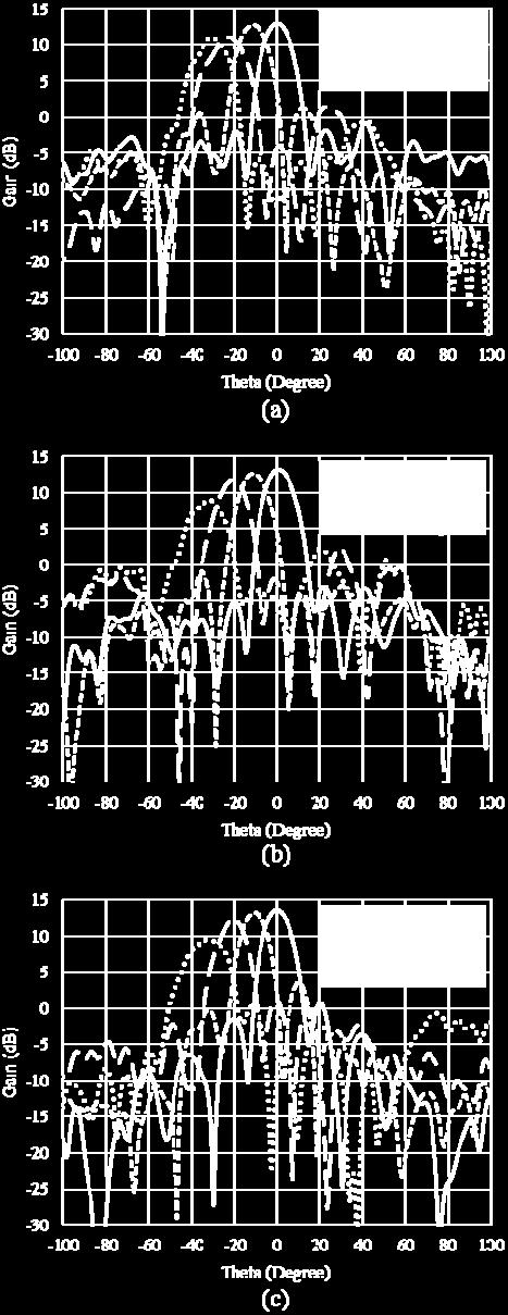
10 42 Design of Rotman Lens Antenna at Ku-Band Based on Substrate Integrated Waveguide Fig. 10. E-plane radiation patterns of SIW Rotman lens antenna at YOZ plane for (a) 15.5 GHz, (b) 16 GHz and (c) 16.5 GHz. (simulated in CST) Fig. 11. E-plane radiation patterns of SIW Rotman lens antenna at YOZ plane for (a) 15.5 GHz, (b) 16 GHz and (c) 16.5 GHz. (simulated in HFSS)
11 Journal of Communication Engineering, Vol. 3, No. 1, Jan.- June Fig. 12. Co-polar and Cross-polar radiation patterns of beam-port4 of SIW Rotman lens antenna at XOZ plane for 16 GHz. (simulated in CST) Also, the co-polar and cross-polar E-field patterns of port B4 of antenna at XOZ plane for center frequency are illustrated in Fig. 12. IV. CONCLUSION A Rotman lens antenna based on SIW technology in center frequency of 16 GHz has been designed in this paper. SIW combines the advantages of lightweight and low cost fabrication of printed circuit and the low loss characteristic of closed structures. This antenna is composed of two parts: Rotman lens and array antenna. In section II a Rotman lens with 7 inputs and 7 outputs has been designed. Also, the design method of SIW has been explained in this section. In section III, an array of Vivaldi antennas has been connected to Rotman lens and the whole structure has been simulated by two full-wave softwares. The results of two simulators have good similarities and show that this kind of Rotman lens antenna has good performance at this frequency band. REFERENCES [1] R. C Hansen, phased array antennas. New Jersey: Wiley & Sons, [2] W. Rotman and R. Turner, Wide-angle microwave lens for line source applications, IEEE Trans. Antennas Propag., vol. 11, no. 6, pp , Nov [3] A. F. Peterson and E. O. Rausch, Scattering matrix integral equation analysis for the design of a waveguide Rotman lens, IEEE Trans. Antennas Propag., vol. 47, no. 5, pp , May [4] P. K. Singhal, R. D. Gupta, and P. C. Sharma, Design and analysis of modified Rotman type multiple beam forming lens, in Proceedings of IEEE TENCON 98. IEEE Region 10 International Conference on Global Connectivity in Energy, Computer, Communication and Control (Cat. No.98CH36229), 1998, vol. 2, pp [5] Y. J. Cheng, W. Hong, K. Wu, Z. Q. Kuai, C. Yu, J. X. Chen, J. Y. Zhou, and H. J. Tang, Substrate Integrated Waveguide (SIW) Rotman Lens and Its Ka-Band Multibeam Array Antenna Applications, IEEE Trans. Antennas Propag., vol. 56, no. 8, pp , Aug [6] T. a. Milligan, Modern Antenna Design. Hoboken, NJ, USA: John Wiley & Sons, Inc., 2005, p. 470.
12 44 Design of Rotman Lens Antenna at Ku-Band Based on Substrate Integrated Waveguide [7] F. Xu and K. Wu, Guided-wave and leakage characteristics of substrate integrated waveguide, IEEE Trans. Microw. Theory Tech., vol. 53, no. 1, pp , Jan [8] D. Deslandes, Design equations for tapered microstrip-to-substrate Integrated Waveguide transitions, in IEEE MTT-S International Microwave Symposium Digest, 2010, pp [9] R. C. Hansen, Design trades for Rotman lenses, IEEE Trans. Antennas Propag., vol. 39, no. 4, pp , Apr
QUADRI-FOLDED SUBSTRATE INTEGRATED WAVEG- UIDE CAVITY AND ITS MINIATURIZED BANDPASS FILTER APPLICATIONS
 Progress In Electromagnetics Research C, Vol. 23, 1 14, 2011 QUADRI-FOLDED SUBSTRATE INTEGRATED WAVEG- UIDE CAVITY AND ITS MINIATURIZED BANDPASS FILTER APPLICATIONS C. A. Zhang, Y. J. Cheng *, and Y. Fan
Design of High Performance Wide Band Rotman Lens In X-Band
 Design of High Performance Wide Band Rotman Lens In X-Band AlirezaBayat #*1, ShayanKajbafVala #, Ashkan Soleimani #3 # Department of communication engineering Imam Khomeini international university, Iran
Research Article A Multibeam Antenna Array Based on Printed Rotman Lens
 Antennas and Propagation Volume 203, Article ID 79327, 6 pages http://dx.doi.org/0.55/203/79327 Research Article A Multibeam Antenna Array Based on Printed Rotman Lens Wang Zongxin, Xiang Bo, and Yang
Effect of Various Slot Parameters in Single Layer Substrate Integrated Waveguide (SIW) Slot Array Antenna for Ku-Band Applications
 Slot Array Antenna for Ku-Band Applications") ACES JOURNAL, Vol. 30, No. 8, August 2015 934 Effect of Various Slot Parameters in Single Layer Substrate Integrated Waveguide (SIW) Slot Array Antenna for Ku-Band Applications S. Moitra 1 and P. S. Bhowmik
ACES JOURNAL, Vol. 30, No. 8, August 2015 934 Effect of Various Slot Parameters in Single Layer Substrate Integrated Waveguide (SIW) Slot Array Antenna for Ku-Band Applications S. Moitra 1 and P. S. Bhowmik
A Review on Substrate Integrated Waveguide and its Microstrip Interconnect
 IOSR Journal of Electronics and Communication Engineering (IOSR-JECE) ISSN: 2278-2834, ISBN: 2278-8735. Volume 3, Issue 5 (Sep. Oct.. 2012), PP 36-40 A Review on Substrate Integrated Waveguide and its
Single-Fed Low-Profile Circularly Polarized Antenna Using Quarter-Mode Substrate Integrated Waveguide with Enhanced Bandwidth
 Progress In Electromagnetics Research C, Vol. 84, 135 145, 18 Single-Fed Low-Profile Circularly Polarized Antenna Using Quarter-Mode Substrate Integrated Waveguide with Enhanced Bandwidth Ni Wang 1, *,
Series Micro Strip Patch Antenna Array For Wireless Communication
 Series Micro Strip Patch Antenna Array For Wireless Communication Ashish Kumar 1, Ridhi Gupta 2 1,2 Electronics & Communication Engg, Abstract- The concept of Microstrip Antenna Array with high efficiency
Broadband transition between substrate integrated waveguide and rectangular waveguide based on ridged steps
 This article has been accepted and published on J-STAGE in advance of copyediting. Content is final as presented. IEICE Electronics Express, Vol.* No.*,*-* Broadband transition between substrate integrated
Development of Low Profile Substrate Integrated Waveguide Horn Antenna with Improved Gain
 Amirkabir University of Technology (Tehran Polytechnic) Amirkabir International Jounrnal of Science & Research Electrical & Electronics Engineering (AIJ-EEE) Vol. 48, No., Fall 016, pp. 63-70 Development
3D radar imaging based on frequency-scanned antenna
 LETTER IEICE Electronics Express, Vol.14, No.12, 1 10 3D radar imaging based on frequency-scanned antenna Sun Zhan-shan a), Ren Ke, Chen Qiang, Bai Jia-jun, and Fu Yun-qi College of Electronic Science
Planar Leaky-Wave Antennas Based on Microstrip Line and Substrate Integrated Waveguide (SIW)
") Forum for Electromagnetic Research Methods and Application Technologies (FERMAT) Planar Leaky-Wave Antennas Based on Microstrip Line and Substrate Integrated Waveguide (SIW) Dr. Juhua Liu liujh33@mail.sysu.edu.cn
Forum for Electromagnetic Research Methods and Application Technologies (FERMAT) Planar Leaky-Wave Antennas Based on Microstrip Line and Substrate Integrated Waveguide (SIW) Dr. Juhua Liu liujh33@mail.sysu.edu.cn
Two-dimensional beam steering array using planar eight-element composite right/left-handed leaky-wave antennas
 RADIO SCIENCE, VOL. 43,, doi:10.1029/2007rs003800, 2008 Two-dimensional beam steering array using planar eight-element composite right/left-handed leaky-wave antennas Atsushi Sanada 1 Received 4 December
A Beam Switching Planar Yagi-patch Array for Automotive Applications
 PIERS ONLINE, VOL. 6, NO. 4, 21 35 A Beam Switching Planar Yagi-patch Array for Automotive Applications Shao-En Hsu, Wen-Jiao Liao, Wei-Han Lee, and Shih-Hsiung Chang Department of Electrical Engineering,
AN L-BAND TAPERED-RIDGE SIW-TO-CPW TRANSITION
 J.N. Smith, Graduate Student Member IEEE, T. Stander, Senior Member IEEE University of Pretoria, Pretoria, South Africa e-mail: jamessmith@ieee.org; tinus.stander@ieee.org AN L-BAND TAPERED-RIDGE SIW-TO-CPW
G. A. Jafarabadi Department of Electronic and Telecommunication Bagher-Aloloom Research Institute Tehran, Iran
 Progress In Electromagnetics Research Letters, Vol. 14, 31 40, 2010 DESIGN OF MODIFIED MICROSTRIP COMBLINE ARRAY ANTENNA FOR AVIONIC APPLICATION A. Pirhadi Faculty of Electrical and Computer Engineering
A Millimeter Wave Center-SIW-Fed Antenna For 60 GHz Wireless Communication
 A Millimeter Wave Center-SIW-Fed Antenna For 60 GHz Wireless Communication M. Karami, M. Nofersti, M.S. Abrishamian, R.A. Sadeghzadeh Faculty of Electrical and Computer Engineering K. N. Toosi University
Research Article A New Kind of Circular Polarization Leaky-Wave Antenna Based on Substrate Integrated Waveguide
 Antennas and Propagation Volume 1, Article ID 3979, pages http://dx.doi.org/1.11/1/3979 Research Article A New Kind of Circular Polarization Leaky-Wave Antenna Based on Substrate Integrated Waveguide Chong
Chalmers Publication Library
 Chalmers Publication Library Parabolic cylindrical reflector antenna at 6 Hz with line feed in gap waveguide technology This document has been downloaded from Chalmers Publication Library (CPL). It is
Broadband Rectangular Waveguide to GCPW Transition
 Progress In Electromagnetics Research Letters, Vol. 46, 107 112, 2014 Broadband Rectangular Waveguide to GCPW Transition Jun Dong 1, *, Tao Yang 1, Yu Liu 1, Ziqiang Yang 1, and Yihong Zhou 2 Abstract
Compact Microstrip Magnetic Yagi Antenna and Array with Vertical Polarization Based on Substrate Integrated Waveguide
 Progress In Electromagnetics Research C, Vol. 59, 135 141, 215 Compact Microstrip Magnetic Yagi Antenna and Array with Vertical Polarization Based on Substrate Integrated Waveguide Zhao Zhang *, Xiangyu
Research Article High Efficiency and Broadband Microstrip Leaky-Wave Antenna
 Active and Passive Electronic Components Volume 28, Article ID 42, pages doi:1./28/42 Research Article High Efficiency and Broadband Microstrip Leaky-Wave Antenna Onofrio Losito Department of Innovation
ENHANCEMENT OF PHASED ARRAY SIZE AND RADIATION PROPERTIES USING STAGGERED ARRAY CONFIGURATIONS
 Progress In Electromagnetics Research C, Vol. 39, 49 6, 213 ENHANCEMENT OF PHASED ARRAY SIZE AND RADIATION PROPERTIES USING STAGGERED ARRAY CONFIGURATIONS Abdelnasser A. Eldek * Department of Computer
THE GENERALIZED CHEBYSHEV SUBSTRATE INTEGRATED WAVEGUIDE DIPLEXER
 Progress In Electromagnetics Research, PIER 73, 29 38, 2007 THE GENERALIZED CHEBYSHEV SUBSTRATE INTEGRATED WAVEGUIDE DIPLEXER Han S. H., Wang X. L., Fan Y., Yang Z. Q., and He Z. N. Institute of Electronic
DESIGN OF OMNIDIRECTIONAL HIGH-GAIN AN- TENNA WITH BROADBAND RADIANT LOAD IN C WAVE BAND
 Progress In Electromagnetics Research C, Vol. 33, 243 258, 212 DESIGN OF OMNIDIRECTIONAL HIGH-GAIN AN- TENNA WITH BROADBAND RADIANT LOAD IN C WAVE BAND S. Lin *, M.-Q. Liu, X. Liu, Y.-C. Lin, Y. Tian,
MICROSTRIP PHASE INVERTER USING INTERDIGI- TAL STRIP LINES AND DEFECTED GROUND
 Progress In Electromagnetics Research Letters, Vol. 29, 167 173, 212 MICROSTRIP PHASE INVERTER USING INTERDIGI- TAL STRIP LINES AND DEFECTED GROUND X.-C. Zhang 1, 2, *, C.-H. Liang 1, and J.-W. Xie 2 1
Broadband and High Efficiency Single-Layer Reflectarray Using Circular Ring Attached Two Sets of Phase-Delay Lines
 Progress In Electromagnetics Research M, Vol. 66, 193 202, 2018 Broadband and High Efficiency Single-Layer Reflectarray Using Circular Ring Attached Two Sets of Phase-Delay Lines Fei Xue 1, *, Hongjian
Design and Demonstration of 1-bit and 2-bit Transmit-arrays at X-band Frequencies
 PIERS ONLINE, VOL. 5, NO. 8, 29 731 Design and Demonstration of 1-bit and 2-bit Transmit-arrays at X-band Frequencies H. Kaouach 1, L. Dussopt 1, R. Sauleau 2, and Th. Koleck 3 1 CEA, LETI, MINATEC, F3854
BROADBAND AND HIGH-GAIN PLANAR VIVALDI AN- TENNAS BASED ON INHOMOGENEOUS ANISOTROPIC ZERO-INDEX METAMATERIALS
 Progress In Electromagnetics Research, Vol. 120, 235 247, 2011 BROADBAND AND HIGH-GAIN PLANAR VIVALDI AN- TENNAS BASED ON INHOMOGENEOUS ANISOTROPIC ZERO-INDEX METAMATERIALS B. Zhou, H. Li, X. Y. Zou, and
Performance Analysis of a Patch Antenna Array Feed For A Satellite C-Band Dish Antenna
 Cyber Journals: Multidisciplinary Journals in Science and Technology, Journal of Selected Areas in Telecommunications (JSAT), November Edition, 2011 Performance Analysis of a Patch Antenna Array Feed For
Design of smart multi-beam mm-wave antennas
 Design of smart multi-beam mm-wave antennas Leonard HaP, Hedley Hansen and Derek Abbott' acentre for Biomedical Engineering and Department of Electrical and Electronic Engineering University of Adelaide
Design of a Novel Compact Cup Feed for Parabolic Reflector Antennas
 Progress In Electromagnetics Research Letters, Vol. 64, 81 86, 2016 Design of a Novel Compact Cup Feed for Parabolic Reflector Antennas Amir Moallemizadeh 1,R.Saraf-Shirazi 2, and Mohammad Bod 2, * Abstract
Design of Multiple Beam Forming Antenna System Using Substrate Integrated Folded Waveguide (SIFW) Technology
 Technology") Progress In Electromagnetics Research B, Vol. 60, 15 34, 2014 Design of Multiple Beam Forming Antenna System Using Substrate Integrated Folded Waveguide (SIFW) Technology Wriddhi Bhowmik 1, *, Shweta Srivastava
Progress In Electromagnetics Research B, Vol. 60, 15 34, 2014 Design of Multiple Beam Forming Antenna System Using Substrate Integrated Folded Waveguide (SIFW) Technology Wriddhi Bhowmik 1, *, Shweta Srivastava
with a Suspended Stripline Feeding
 Wide Band and High Gain Planar Array with a Suspended Stripline Feeding Network N. Daviduvitz, U. Zohar and R. Shavit Dept. of Electrical and Computer Engineering Ben Gurion University i of the Negev,
Research Article A Novel SIW H-Plane Horn Antenna Based on Parabolic Reflector
 Antennas and Propagation Volume 216, Article ID 365923, 7 pages http://dx.doi.org/1.1155/216/365923 Research Article A Novel SIW H-Plane Horn Antenna Based on Parabolic Reflector Shiqiao Zhang, Zheng Li,
PUSH-PUSH DIELECTRIC RESONATOR OSCILLATOR USING SUBSTRATE INTEGRATED WAVEGUIDE POW- ER COMBINER
 Progress In Electromagnetics Research Letters, Vol. 30, 105 113, 2012 PUSH-PUSH DIELECTRIC RESONATOR OSCILLATOR USING SUBSTRATE INTEGRATED WAVEGUIDE POW- ER COMBINER P. Su *, Z. X. Tang, and B. Zhang School
A Pin-Loaded Microstrip Patch Antenna with the Ability to Suppress Surface Wave Excitation
 Progress In Electromagnetics Research C, Vol. 62, 131 137, 2016 A Pin-Loaded Microstrip Patch Antenna with the Ability to Suppress Surface Wave Excitation Ayed R. AlAjmi and Mohammad A. Saed * Abstract
Broadband Balanced Microstrip Antenna Fed by a Waveguide Coupler
 278 Broadband Balanced Microstrip Antenna Fed by a Waveguide Coupler R. Gotfrid*, Z. Luvitzky*, H. Matzner* and E. Levine** * HIT, Holon Institute of Technology Department of Communication Engineering,
Sensor and Simulation Notes Note 548 October 2009
 Sensor and Simulation Notes Note 548 October 009 Design of a rectangular waveguide narrow-wall longitudinal-aperture array using microwave network analysis Naga R. Devarapalli, Carl E. Baum, Christos G.
CHAPTER 2 MICROSTRIP REFLECTARRAY ANTENNA AND PERFORMANCE EVALUATION
 43 CHAPTER 2 MICROSTRIP REFLECTARRAY ANTENNA AND PERFORMANCE EVALUATION 2.1 INTRODUCTION This work begins with design of reflectarrays with conventional patches as unit cells for operation at Ku Band in
DESIGN AND ANALYSIS OF MICROSTRIP FED SLOT ANTENNA FOR SMALL SATELLITE APPLICATIONS
 I J I T E ISSN: 2229-7367 3(1-2), 2012, pp. 353-358 DESIGN AND ANALYSIS OF MICROSTRIP FED SLOT ANTENNA FOR SMALL SATELLITE APPLICATIONS ELAMARAN P. 1 & ARUN V. 2 1 M.E-Communication systems, Anna University
A HIGH-POWER LOW-LOSS MULTIPORT RADIAL WAVEGUIDE POWER DIVIDER
 Progress In Electromagnetics Research Letters, Vol. 31, 189 198, 2012 A HIGH-POWER LOW-LOSS MULTIPORT RADIAL WAVEGUIDE POWER DIVIDER X.-Q. Li *, Q.-X. Liu, and J.-Q. Zhang School of Physical Science and
Design of Crossbar Mixer at 94 GHz
 Wireless Sensor Network, 2015, 7, 21-26 Published Online March 2015 in SciRes. http://www.scirp.org/journal/wsn http://dx.doi.org/10.4236/wsn.2015.73003 Design of Crossbar Mixer at 94 GHz Sanjeev Kumar
ANALYSIS OF EPSILON-NEAR-ZERO METAMATE- RIAL SUPER-TUNNELING USING CASCADED ULTRA- NARROW WAVEGUIDE CHANNELS
 Progress In Electromagnetics Research M, Vol. 14, 113 121, 21 ANALYSIS OF EPSILON-NEAR-ZERO METAMATE- RIAL SUPER-TUNNELING USING CASCADED ULTRA- NARROW WAVEGUIDE CHANNELS J. Bai, S. Shi, and D. W. Prather
Gain Enhancement of Pyramidal Horn Antenna using EBG Technique
 International Journal of Current Engineering and Technology E-ISSN 2277 4106, P-ISSN 2347 5161 2015INPRESSCO, All Rights Reserved Available at http://inpressco.com/category/ijcet Research Article Sheelu
A New Multi-Functional Half Mode Substrate Integrated Waveguide Six-Port Microwave Component
 Progress In Electromagnetics Research Letters, Vol. 69, 71 78, 2017 A New Multi-Functional Half Mode Substrate Integrated Waveguide Six- Microwave Component Saeid Karamzadeh 1, 2, *,VahidRafiei 2, and
NOVEL TWO-LAYER MILLIMETER-WAVE SLOT AR- RAY ANTENNAS BASED ON SUBSTRATE INTE- GRATED WAVEGUIDES
 Progress In Electromagnetics Research, Vol. 19, 475 491, 21 NOVEL TWO-LAYER MILLIMETER-WAVE SLOT AR- RAY ANTENNAS BASED ON SUBSTRATE INTE- GRATED WAVEGUIDES A. Bakhtafrooz and A. Borji Department of Electrical
L-BAND COPLANAR SLOT LOOP ANTENNA FOR INET APPLICATIONS
 L-BAND COPLANAR SLOT LOOP ANTENNA FOR INET APPLICATIONS Jeyasingh Nithianandam Electrical and Computer Engineering Department Morgan State University, 500 Perring Parkway, Baltimore, Maryland 5 ABSTRACT
DESIGN AND PERFORMANCE OF A K U -BAND ROT- MAN LENS BEAMFORMING NETWORK FOR SATEL- LITE SYSTEMS
 Progress In Electromagnetics Research M, Vol. 28, 41 55, 2013 DESIGN AND PERFORMANCE OF A K U -BAND ROT- MAN LENS BEAMFORMING NETWORK FOR SATEL- LITE SYSTEMS Ardavan Rahimian * School of Electronic, Electrical
ENHANCEMENT OF PRINTED DIPOLE ANTENNAS CHARACTERISTICS USING SEMI-EBG GROUND PLANE
 J. of Electromagn. Waves and Appl., Vol. 2, No. 8, 993 16, 26 ENHANCEMENT OF PRINTED DIPOLE ANTENNAS CHARACTERISTICS USING SEMI-EBG GROUND PLANE F. Yang, V. Demir, D. A. Elsherbeni, and A. Z. Elsherbeni
DESIGN OF LEAKY WAVE ANTENNA WITH COM- POSITE RIGHT-/LEFT-HANDED TRANSMISSION LINE STRUCTURE FOR CIRCULAR POLARIZATION RADIA- TION
 Progress In Electromagnetics Research C, Vol. 33, 109 121, 2012 DESIGN OF LEAKY WAVE ANTENNA WITH COM- POSITE RIGHT-/LEFT-HANDED TRANSMISSION LINE STRUCTURE FOR CIRCULAR POLARIZATION RADIA- TION M. Ishii
Planar Wideband Balun with Novel Slotline T-Junction Transition
 Progress In Electromagnetics Research Letters, Vol. 64, 73 79, 2016 Planar Wideband Balun with Novel Slotline T-Junction Transition Ya-Li Yao*, Fu-Shun Zhang, Min Liang, and Mao-Ze Wang Abstract A planar
Substrate Integrated Waveguide Coupler
 41, Issue 1 (2018) 7-14 Journal of Advanced Research Design Journal homepage: www.akademiabaru.com/ard.html ISSN: 2289-7984 Substrate Integrated Waveguide Coupler Open Access A.M.M.A Allam 1,, Adham Mahmoud
Design of Microstrip Array Antenna for WiMAX and Ultra-Wideband Applications
 Design of Microstrip Array Antenna for WiMAX and Ultra-Wideband Applications 1. Abhishek Awasthi, 2. Mrs. Garima Saini 1. Student, ME (Modular), Department of Electronics and Communication Engineering
RCS Reduction of Patch Array Antenna by Complementary Split-Ring Resonators Structure
 Progress In Electromagnetics Research C, Vol. 51, 95 101, 2014 RCS Reduction of Patch Array Antenna by Complementary Split-Ring Resonators Structure Jun Zheng 1, 2, Shaojun Fang 1, Yongtao Jia 3, *, and
TRANSMITTING ANTENNA WITH DUAL CIRCULAR POLARISATION FOR INDOOR ANTENNA MEASUREMENT RANGE
 TRANSMITTING ANTENNA WITH DUAL CIRCULAR POLARISATION FOR INDOOR ANTENNA MEASUREMENT RANGE Michal Mrnka, Jan Vélim Doctoral Degree Programme (2), FEEC BUT E-mail: xmrnka01@stud.feec.vutbr.cz, velim@phd.feec.vutbr.cz
This is a repository copy of Compact Broadband Electronically Controllable SIW Phase Shifter for 5G Phased Array Antennas.
 This is a repository copy of Compact Broadband Electronically Controllable SIW Phase Shifter for 5G Phased Array Antennas. White Rose Research Online URL for this paper: http://eprints.whiterose.ac.uk/126379/
Copyright 2004 IEEE. Reprinted from IEEE AP-S International Symposium 2004
 Copyright IEEE Reprinted from IEEE AP-S International Symposium This material is posted here with permission of the IEEE. Such permission of the IEEE does not in any way imply IEEE endorsement of any of
Research Article Analysis and Design of Leaky-Wave Antenna with Low SLL Based on Half-Mode SIW Structure
 Antennas and Propagation Volume 215, Article ID 57693, 5 pages http://dx.doi.org/1.1155/215/57693 Research Article Analysis and Design of Leaky-Wave Antenna with Low SLL Based on Half-Mode SIW Structure
Postwall waveguide slot array with cosecant radiation pattern and null filling for base station antennas in local multidistributed systems
 RADIO SCIENCE, VOL. 38, NO. 2, 8009, doi:10.1029/2001rs002580, 2003 Postwall waveguide slot array with cosecant radiation pattern and null filling for base station antennas in local multidistributed systems
CIRCULARLY POLARIZED SLOTTED APERTURE ANTENNA WITH COPLANAR WAVEGUIDE FED FOR BROADBAND APPLICATIONS
 Journal of Engineering Science and Technology Vol. 11, No. 2 (2016) 267-277 School of Engineering, Taylor s University CIRCULARLY POLARIZED SLOTTED APERTURE ANTENNA WITH COPLANAR WAVEGUIDE FED FOR BROADBAND
Smart Antenna System using 4x4 Butler Matrix switched beam network for 2.4 GHz ISM band
 Smart Antenna System using 4x4 Butler Matrix switched beam network for 2.4 GHz ISM band Prof. F I Shaikh 1, Mr. Sanjay Bansidhar Akhade 2 1 Electronics and Telecommunication department J. N. E. C. Aurangabad
DOUBLE-RIDGED ANTENNA FOR WIDEBAND APPLI- CATIONS. A. R. Mallahzadeh and A. Imani Electrical Engineering Department Shahed University Tehran, Iran
 Progress In Electromagnetics Research, PIER 91, 273 285, 2009 DOUBLE-RIDGED ANTENNA FOR WIDEBAND APPLI- CATIONS A. R. Mallahzadeh and A. Imani Electrical Engineering Department Shahed University Tehran,
Multilayered Substrate-Integrated Waveguide Couplers
 Multilayered Substrate-Integrated Waveguide Couplers Vladimir A. Labay Department of Electrical and Computer Engineering Gonzaga University, Spokane, WA 99258, USA Jens Bornemann Department of Electrical
A Wideband Stacked Microstrip Patch Antenna for Telemetry Applications
 A Wideband Stacked Microstrip Patch Antenna for Telemetry Applications Item Type text; Proceedings Authors Hategekimana, Bayezi Publisher International Foundation for Telemetering Journal International
Design of Asymmetric Dual-Band Microwave Filters
 Progress In Electromagnetics Research Letters, Vol. 67, 47 51, 2017 Design of Asymmetric Dual-Band Microwave Filters Zhongxiang Zhang 1, 2, *, Jun Ding 3,ShuoWang 2, and Hua-Liang Zhang 3 Abstract This
A COMPACT MULTILAYER DUAL-MODE SUBSTRATE INTEGRATED CIRCULAR CAVITY (SICC) FILTER FOR X-BAND APPLICATION
 FILTER FOR X-BAND APPLICATION") Progress In Electromagnetics Research, Vol. 122, 453 465, 2012 A COMPACT MULTILAYER DUAL-MODE SUBSTRATE INTEGRATED CIRCULAR CAVITY (SICC) FILTER FOR X-BAND APPLICATION Z.-G. Zhang *, Y. Fan, Y.-J. Cheng,
Progress In Electromagnetics Research, Vol. 122, 453 465, 2012 A COMPACT MULTILAYER DUAL-MODE SUBSTRATE INTEGRATED CIRCULAR CAVITY (SICC) FILTER FOR X-BAND APPLICATION Z.-G. Zhang *, Y. Fan, Y.-J. Cheng,
Circular Focal Plane Array for Astronomic Applications
 International Workshop on Phased Array Antenna Systems for Radio Astronomy Circular Focal Plane Array for Astronomic Applications Rémi Sarkis, Christophe Craeye May 3-5, 21 Provo, Utah, USA 1 Introduction
6464(Print), ISSN (Online) ENGINEERING Volume & 3, Issue TECHNOLOGY 3, October- December (IJECET) (2012), IAEME
, ISSN (Online) ENGINEERING Volume & 3, Issue TECHNOLOGY 3, October- December (IJECET) (2012), IAEME") International INTERNATIONAL Journal of Electronics JOURNAL and Communication OF ELECTRONICS Engineering AND & Technology COMMUNICATION (IJECET), ISSN 0976 6464(Print), ISSN 0976 6472(Online) ENGINEERING
International INTERNATIONAL Journal of Electronics JOURNAL and Communication OF ELECTRONICS Engineering AND & Technology COMMUNICATION (IJECET), ISSN 0976 6464(Print), ISSN 0976 6472(Online) ENGINEERING
Exact Synthesis of Broadband Three-Line Baluns Hong-Ming Lee, Member, IEEE, and Chih-Ming Tsai, Member, IEEE
 140 IEEE TRANSACTIONS ON MICROWAVE THEORY AND TECHNIQUES, VOL. 57, NO. 1, JANUARY 2009 Exact Synthesis of Broadband Three-Line Baluns Hong-Ming Lee, Member, IEEE, and Chih-Ming Tsai, Member, IEEE Abstract
Couple-fed Circular Polarization Bow Tie Microstrip Antenna
 PIERS ONLINE, VOL., NO., Couple-fed Circular Polarization Bow Tie Microstrip Antenna Huan-Cheng Lien, Yung-Cheng Lee, and Huei-Chiou Tsai Wu Feng Institute of Technology Chian-Ku Rd., Sec., Ming-Hsiung
COMPACT PLANAR MICROSTRIP CROSSOVER FOR BEAMFORMING NETWORKS
 Progress In Electromagnetics Research C, Vol. 33, 123 132, 2012 COMPACT PLANAR MICROSTRIP CROSSOVER FOR BEAMFORMING NETWORKS B. Henin * and A. Abbosh School of ITEE, The University of Queensland, QLD 4072,
IEEE ANTENNAS AND WIRELESS PROPAGATION LETTERS, VOL. 7, /$ IEEE
 IEEE ANTENNAS AND WIRELESS PROPAGATION LETTERS, VOL. 7, 2008 369 Design and Development of a Novel Compact Soft-Surface Structure for the Front-to-Back Ratio Improvement and Size Reduction of a Microstrip
EFFECT ON PERFORMANCE CHARACTERISTICS OF RECTANGULAR PATCH ANTENNA WITH VARYING HEIGHT OF DIELECTRIC COVER
 International Journal of Power Control Signal and Computation (IJPCSC) Vol. 2 No. 1 ISSN : 0976-268X EFFECT ON PERFORMANCE CHARACTERISTICS OF RECTANGULAR PATCH ANTENNA WITH VARYING HEIGHT OF DIELECTRIC
A Wideband Dual-polarized Modified Bowtie Antenna for 2G/3G/LTE Base-station Applications
 Progress In Electromagnetics Research Letters, Vol. 61, 131 137, 2016 A Wideband Dual-polarized Modified Bowtie Antenna for 2G/3G/LTE Base-station Applications Zhao Yang *, Cilei Zhang, Yingzeng Yin, and
A K-Band Flat Transmitarray Antenna with a Planar Microstrip Slot-Fed Patch Antenna Feeder
 Progress In Electromagnetics Research C, Vol. 64, 97 104, 2016 A K-Band Flat Transmitarray Antenna with a Planar Microstrip Slot-Fed Patch Antenna Feeder Lv-Wei Chen and Yuehe Ge * Abstract A thin phase-correcting
X. Li, L. Yang, S.-X. Gong, and Y.-J. Yang National Key Laboratory of Antennas and Microwave Technology Xidian University Xi an, Shaanxi, China
 Progress In Electromagnetics Research Letters, Vol. 6, 99 16, 29 BIDIRECTIONAL HIGH GAIN ANTENNA FOR WLAN APPLICATIONS X. Li, L. Yang, S.-X. Gong, and Y.-J. Yang National Key Laboratory of Antennas and
Gain Enhancement and Wideband RCS Reduction of a Microstrip Antenna Using Triple-Band Planar Electromagnetic Band-Gap Structure
 Progress In Electromagnetics Research Letters, Vol. 65, 103 108, 2017 Gain Enhancement and Wideband RCS Reduction of a Microstrip Antenna Using Triple-Band Planar Electromagnetic Band-Gap Structure Yang
Electronic Beam Scanning for 5G with a Rotman Lens Mike Gleaves, CTO, Arralis Limited, Limerick, Ireland
 Electronic Beam Scanning for 5G with a Rotman Lens Mike Gleaves, CTO, Arralis Limited, Limerick, Ireland Introduction There is much hype about 5G at present but as yet there are no standards or internationally
Half-Mode Slow-Wave Substrate Integrated Waveguide Analysis
 Progress In Electromagnetics Research M, Vol. 60, 169 178, 2017 Half-Mode Slow-Wave Substrate Integrated Waveguide Analysis Mohamad Khalil 1, 2, Mahmoud Kamarei 1, *, Jalal Jomaah 2, Hussam Ayad 2, and
A 3 20GHz Vivaldi Antenna with Modified Edge
 A 3 20GHz Vivaldi Antenna with Modified Edge Bieng-Chearl Ahn* * and Otgonbaatar Gombo Applied Electromagnetics Laboratory, Department of Radio and Communications Engineering Chungbuk National University,
A Broadband Omnidirectional Antenna Array for Base Station
 Progress In Electromagnetics Research C, Vol. 54, 95 101, 2014 A Broadband Omnidirectional Antenna Array for Base Station Bo Wang 1, *, Fushun Zhang 1,LiJiang 1, Qichang Li 2, and Jian Ren 1 Abstract A
4324 IEEE TRANSACTIONS ON ANTENNAS AND PROPAGATION, VOL. 63, NO. 10, OCTOBER 2015
 4324 IEEE TRANSACTIONS ON ANTENNAS AND PROPAGATION, VOL. 63, NO. 10, OCTOBER 2015 A Low Cross-Polarization Slotted Ridged SIW Array Antenna Design With Mutual Coupling Considerations Alireza Mallahzadeh,
Effects of Two Dimensional Electromagnetic Bandgap (EBG) Structures on the Performance of Microstrip Patch Antenna Arrays
 Structures on the Performance of Microstrip Patch Antenna Arrays") Effects of Two Dimensional Electromagnetic Bandgap (EBG) Structures on the Performance of Microstrip Patch Antenna Arrays Mr. F. Benikhlef 1 and Mr. N. Boukli-Hacen 2 1 Research Scholar, telecommunication,
Effects of Two Dimensional Electromagnetic Bandgap (EBG) Structures on the Performance of Microstrip Patch Antenna Arrays Mr. F. Benikhlef 1 and Mr. N. Boukli-Hacen 2 1 Research Scholar, telecommunication,
Progress In Electromagnetics Research C, Vol. 9, 13 23, 2009
 Progress In Electromagnetics Research C, Vol. 9, 13 23, 2009 PATCH ANTENNA WITH RECONFIGURABLE POLARIZATION G. Monti, L. Corchia, and L. Tarricone Department of Innovation Engineering University of Salento
Long Slot Ridged SIW Leaky Wave Antenna Design Using Transverse Equivalent Technique
 IEEE TRANSACTIONS ON ANTENNAS AND PROPAGATION, VOL. 62, NO. 11, NOVEMBER 2014 5445 Long Slot Ridged SIW Leaky Wave Antenna Design Using Transverse Equivalent Technique Alireza Mallahzadeh, Member, IEEE,
DESIGN OF MID-BAND FREQUENCY PATCH ANTENNA FOR 5G APPLICATIONS
 DESIGN OF MID-BAND FREQUENCY PATCH ANTENNA FOR 5G APPLICATIONS HARINI. D 1, JAGADESHWAR. V 2, MOHANAPRIYA. E 3, SHERIBA. T.S 4 1,2,3Student, Dept. of ECE Engineering, Valliammai Engineering College, Tamil
A NOVEL DUAL-BAND PATCH ANTENNA FOR WLAN COMMUNICATION. E. Wang Information Engineering College of NCUT China
 Progress In Electromagnetics Research C, Vol. 6, 93 102, 2009 A NOVEL DUAL-BAND PATCH ANTENNA FOR WLAN COMMUNICATION E. Wang Information Engineering College of NCUT China J. Zheng Beijing Electro-mechanical
Performance Analysis of Different Ultra Wideband Planar Monopole Antennas as EMI sensors
 International Journal of Electronics and Communication Engineering. ISSN 09742166 Volume 5, Number 4 (2012), pp. 435445 International Research Publication House http://www.irphouse.com Performance Analysis
Reduction of Mutual Coupling between Cavity-Backed Slot Antenna Elements
 Progress In Electromagnetics Research C, Vol. 53, 27 34, 2014 Reduction of Mutual Coupling between Cavity-Backed Slot Antenna Elements Qi-Chun Zhang, Jin-Dong Zhang, and Wen Wu * Abstract Maintaining mutual
DIELECTRIC ROTMAN LENS ALTERNATIVES FOR BROADBAND MULTIPLE BEAM ANTENNAS IN MULTI-FUNCTION RF APPLICATIONS. O. Kilic U.S. Army Research Laboratory
 DIELECTRIC ROTMAN LENS ALTERNATIVES FOR BROADBAND MULTIPLE BEAM ANTENNAS IN MULTI-FUNCTION RF APPLICATIONS O. Kilic U.S. Army Research Laboratory ABSTRACT The U.S. Army Research Laboratory (ARL) is currently
Progress In Electromagnetics Research C, Vol. 26, , 2012
 Progress In Electromagnetics Research C, Vol. 26, 97 110, 2012 DESIGN OF A WIDE BAND EIGHT-WAY COMPACT SIW POWER COMBINER FED BY A LOW LOSS GCPW- TO-SIW TRANSITION R. Kazemi 1, *, R. A. Sadeghzadeh 1,
Slotline Leaky Wave Antenna with a Stacked Substrate
 Progress In Electromagnetics Research Symposium 26, Cambridge, USA, March 26-29 283 Slotline Leaky Wave Antenna with a Stacked Substrate J. Macháč, J. Hruška, and J. Zehentner Czech Technical University,
Compact Microstrip UWB Power Divider with Dual Notched Bands Using Dual-Mode Resonator
 Progress In Electromagnetics Research Letters, Vol. 75, 39 45, 218 Compact Microstrip UWB Power Divider with Dual Notched Bands Using Dual-Mode Resonator Lihua Wu 1, Shanqing Wang 2,LuetaoLi 3, and Chengpei
VERTICAL TRANSITION IN MULTILAYER MILLIMETER WAVE MODULE USING CIRCULAR CAVITY
 Progress In Electromagnetics Research M, Vol. 5, 91 100, 2008 VERTICAL TRANSITION IN MULTILAYER MILLIMETER WAVE MODULE USING CIRCULAR CAVITY D. Wu, Y. Fan, M. Zhao, and Y. Zhang School of Electronic Engineering
Design of Substrate IntegratedWaveguide Power Divider and Parameter optimization using Neural Network
 IOSR Journal of Electronics and Communication Engineering (IOSR-JECE) e-issn: 2278-2834,p- ISSN: 2278-8735.Volume 13, Issue 1, Ver. I (Jan.- Feb. 2018), PP 37-43 www.iosrjournals.org Design of Substrate
Design and Measurement of a Novel Seamless Scanning Leaky Wave Antenna in Ridge Gap Waveguide Technology
 Progress In Electromagnetics Research M, Vol. 58, 147 157, 2017 Design and Measurement of a Novel Seamless Scanning Leaky Wave Antenna in Ridge Gap Waveguide Technology Xingchao Dong 1, 2, *,HongjianWang
DESIGN OF A NOVEL BROADBAND EMC DOUBLE RIDGED GUIDE HORN ANTENNA
 Progress In Electromagnetics Research C, Vol. 39, 225 236, 2013 DESIGN OF A NOVEL BROADBAND EMC DOUBLE RIDGED GUIDE HORN ANTENNA Tenigeer *, Ning Zhang, Jinghui Qiu, Pengyu Zhang, and Yang Zhang School
A broadband 180 hybrid ring coupler using a microstrip-to-slotline inverter Riaan Ferreira and Johan Joubert
 A broadband 180 hybrid ring coupler using a microstrip-to-slotline inverter Riaan Ferreira and Johan Joubert Centre for Electromagnetism, Department of EEC Engineering, University of Pretoria, Pretoria,
DIELECTRIC LOADED EXPONENTIALLY TAPERED SLOT ANTENNA FOR WIRELESS COMMUNICATIONS AT 60 GHz
 Progress In Electromagnetics Research C, Vol. 38, 43 54, 2013 DIELECTRIC LOADED EXPONENTIALLY TAPERED SLOT ANTENNA FOR WIRELESS COMMUNICATIONS AT 60 GHz Subramaniam Ramesh and Thipparaju R. Rao * RADMIC,
A BROADBAND QUADRATURE HYBRID USING IM- PROVED WIDEBAND SCHIFFMAN PHASE SHIFTER
 Progress In Electromagnetics Research C, Vol. 11, 229 236, 2009 A BROADBAND QUADRATURE HYBRID USING IM- PROVED WIDEBAND SCHIFFMAN PHASE SHIFTER E. Jafari, F. Hodjatkashani, and R. Rezaiesarlak Department