SUPER INVERTER SERIES MULTI TYPE. Service Manual 2018
|
|
|
- Julius Wilkins
- 5 years ago
- Views:
Transcription
1 SUPER INVERTER SERIES MULTI TYPE Service Manual 2018
2 CONTENTS 1. General information of Indoor Units Features Dimensions Service Space (unit: mm) Wiring diagram Static Pressure (Duct) Operation temperature range Electronic function General information of Outdoor Units Features Dimensions Refrigeration Cycle Diagram Wiring diagram Indoor units combination Sound Levels Installation Details Electronic control function Troubleshooting... 67
3 The specifications, designs, and information in this book are subject to change without notice for product improvement.
")


")


4 1. General information of Indoor Units Four-way cassette (compact) Silm cassette Console 15C A5 Ducted A6 Ducted ODU 38QUS014DS2* 38QUS014DS2-2 38QUS018DS2* 38QUS018DS2-2 38QUS027DS3* 38QUS036DS4* 38QUS042DS5* Model Four-way cassette (compact) 42QTD007D8S 42QTD009D8S Super slim cassette Console 15C A5 Duct A6 Duct ODU 42QTD024DS* 38QUS014DS2* 38QUS014DS2-2 38QUS018DS2* 38QUS018DS2-2 42QTD012D8S 42QZA018DS* 42QHC012D8S 42QSS012D8S 38QUS021DS3* 42QTD018D8S 42QHC018D8S 42QSS018DS* 38QUS027DS3* 42QHC024D8S 42QSS024DS* 38QUS028DS4* *Model with gray Mark was phased. 42QZA009DS* 42QZA012DS* 42QHC007D8S 42QHC009D8S 42QSS012DS* 42QSS007D8S 42QSS009D8S 38QUS036DS4* 38QUS042DS5* 1
 ⑴ New panel 360 surrounding air outlet")


5 2. Features 2.1 Four-way cassette type(compact) ⑴ New panel 360 surrounding air outlet design, affords comfortable feeling ⑵ Compact design The body size is mm, it s just smaller than the ceiling board, so it s very easy for installation and will not damage the decoration. The panel size is mm. The hooks are designed in the four corners of the body, which can save installation space. ⑶ Electric control box built-in design The E-box is simply and safely built inside the indoor unit. It s convenient for installation and maintenance. Can check the control part easily, you only need to open the air return grille. ⑷ Fresh air intake function: Fresh air fulfills air quality more healthy and comfortable. 2


6 Fresh Air Dimension:Φ75mm ⑸ Air passage function Reserves the space for air outlet from the side of indoor unit; It s availed to connect air duct from the two sides to the nearby small rooms. 3


 Air intake from bottom (Optional) ⑶ Fresh air")

 It")
7 2.2 A5 Duct ⑴ Installation accessories: (Optional) Front Board, Canvas Air Passage, Filter, Panel, for easy installation Front Board Filter Panel ⑵ Easy Installation: Two air inlet styles (Bottom side or Rear side) Air inlet from rear is standard for all capacity; air inlet from bottom is optional. The size of air inlet frame from rear and bottom is same, it s very easy to move the cover from bottom to rear side, or from rear to the bottom, in order to matching the installation condition. Air intake from rear (Standard) Air intake from bottom (Optional) ⑶ Fresh air intake function Install one duct from the reserved fresh-air intake to outdoor. Continually inhale the fresh air to improve the quality of the indoor air, fulfills air quality more healthy and comfortable. ⑷ Easy maintenance Clean the filter (Optional, standard product without filter) It is easy to draw out the filter from the indoor unit for cleaning, even the filter is installed in rear side or bottom side. 4


8 Replace the motor or centrifugal fan Remove the ventilated panel firstly. Remove a half of blower housing and take out the motor with centrifugal fan. Directly remove two bolts, and then replace the motor or centrifugal fan easily. Motor Blower Housing Ventilated Panel ⑸ Reserved remote on-off and central control ports Reserved remote on-off ports and central control ports, can connect the cable of an on-off controller or a central controller to realize remote on-off control function or group control function. 5
: Built-in drain pump can lift the water to")


9 Remote on-off ports Central control ports ⑹ Built-in drain pump (Optional): Built-in drain pump can lift the water to 750mm upmost. It s convenient to install drainage piping under most space condition. 750mm upmost ⑺ Built-in display board The standard indoor unit can be controlled by wired controller. There is a display board with a receiver in the E-box. Move out the display, and fix it in other place, even in the distance of 10m. The unit will realized remoter control. The wired controller and the display board can display the error code or production code when the chips detect some failure. 6
 Consumes up to 30% less energy than non-inverter units DC inverter compressor indoor fan motor adopts DC motor (2) Achieves set temperature more quickly air supplying")
 Flexible installation.")
 High efficiency filter built in Formaldehyde nemesis filter active-carbon and biological anti-virus filter is optional.")
10 Wired Controller (Standard) Remote Controller (Optional) Display 2.3 Console (1) Consumes up to 30% less energy than non-inverter units DC inverter compressor indoor fan motor adopts DC motor (2) Achieves set temperature more quickly air supplying from top and bottom or from top only air inlet from four directions (3) Compact unit body, space saving this unit body is very thin and harmonious with room. It is beautiful, elegant and space saving. light weight and compact. (4) Flexible installation. can be used for floor standing or lower wall applications as a floor standing floor model, it can be semi or fully recessed without loss of capacity. (5) High efficiency filter built in Formaldehyde nemesis filter active-carbon and biological anti-virus filter is optional. (6) Comfort flexible air blow: vertical auto swing and wide angle louvers ensure that warm air reaches the furthest corners of the room and increase the air flow coverage Low noise operation, lowest to 23Db Low starting power and precise room temperature adjustment (7) Powerful mode can be selected for rapid cooling or heating. 7
 Overview Compact design, super slim body size, less space requiring in installation Each louver can be separately controlled,")
 (2) Fresh air intake function Fresh air fulfills air quality more healthy and comfortable.")
 Optional ionizer generator Ionizer generator is optional to get refreshing air to your room.")
11 (8) Easy cleaning grille and maintenance (9) Indoor unit adopts DC motor, it has five level fan speed meet different requirements. 7.4 Super slim cassette (1) Overview Compact design, super slim body size, less space requiring in installation Each louver can be separately controlled, more comfort air blowing is possible. Auto-lifting panel design, more convenient to clean and maintain the filter. (optional) (2) Fresh air intake function Fresh air fulfills air quality more healthy and comfortable. Ventilation motor is optional to increase the effect of fresh air. (3) Optional ionizer generator Ionizer generator is optional to get refreshing air to your room. Ionizer generator connector Ventilation motor connector Ionizer can be switched on or off by remote controller. When pressing the Clean Air button on the remote controller, Ionizer will work and the indicator light on display board will shine. 8

 Built-in draining pump Due to the")


12 (4) External air duct design Reserve external air duct, more flexible for the air supply. (5) Built-in draining pump Due to the improvement of structure, more convenient to repair or replace the draining pump. Built-in draining pump to make sure condensed water drain out reliably. Draining Pump (6) Terminals for alarm lamp and long-distance on-off controller connection are standard Reserve terminals for the connection of alarm lamp and long-distance on-off controller, more human control. 9
 New design, more modern and elegant appearance.")

 Two direction auto swing (vertical & horizontal) and wide angle air flow, --Air flow directional")

13 Alarm lamp Long-distance on-off controller 7.5 Ceiling-Floor (1) New design, more modern and elegant appearance. (2) Convenient installation --The ceiling type can be easily installed into a corner of the ceiling even if the ceiling is very narrow --It is especially useful when installation of an air conditioner in the center of the ceiling is impossible due to a structure such as one lighting. (3) Two direction auto swing (vertical & horizontal) and wide angle air flow, --Air flow directional control minimizes the air resistance and produces wilder air flow to vertical direction. --The range of horizontal air discharge is widened which secures wider air flow distribution to provide more comfortable air circulation no matter where the unit is set up (4) New foam drain pan with plastic-spraying inner surface 10
 Remote control and optional wired")
14 (5) Easy operation. (6) Remote control and optional wired control method. 11
15 3. Dimensions 3.1 Four-way cassette type (compact): L iq u id s id e G a s s id e B o d y D ra in h o le ( fo r S e rv ic e ) 4 -in s ta ll h a n g e r D is trib u tio n d u c t E -p a rts b o x 4 -S c re w h o le (fo r in s ta ll p a n e l) F re s h a ir in ta k e 32 D ra in p ip e 75 W irin g c o n n e c tio n p o rt P a n e l
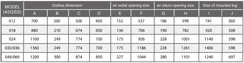
16 3.2 A5 Duct a i r i n l e t f r o m r e a r s i d e A i r f i l t e r ( o p t i o n a l ) J I H2 H1 4 - i n s t a l l h a n g e r A L L i q u i d s i d e B W2 W1 2 5 D ra in p ip e G a s s i d e T e s t m o u th & T e s t c o v e r M 2 5 D ra in p ip e D C 2 5 D ra in c o n n e c tin g p ip e ( fo r p u m p ) E l e c t r i c c o n t r Fore l s h abir oin taxk e G E F K H A i r f i l t e r ( o p t i o n a l ) a i r i n l e t f r o m b o t t o m s i d e te: standard product without filter Unit: mm Model Outline dimension(mm) Air outlet opening size Air return opening size Size of install hanger Size of refrigerant pipe A B C D E F G H I J K L M H1 H2 W1 W2 42QSS012DS*
17 3.3 Console H a n g in g a rm D ra in p ip e 14
18 3.4 Super-Slim Cassette Type Fresh air intake D A W irin g c o n n e c tio n p o rt A D ra in h o le T e s t m o u th & T e s t c o v e r 840 C A B A A B A D 80 B 80 D D 4 -install hanger G a s s id e B o d y L iq u id s id e E -p a rts b o x A S ervice hole for d ra in in g p u m p B D D D D P a n e l Unit: mm Model A B C D 42QTD024DS*
19 3.5 Ceiling &Floor Type W irin g c o n n e c tio n p o rt D r a in d is c h a rg e p o rt B C A Fresh air intake R e fr ig e r a n t p ip e h o le D H a n g in g a rm Capacity (KBtu/h) A B C D 18/
20 3.6 Ducted A5 17
21 A6 18
22 3.7 Hi-wall Indoor Unit Model (KBtu/h) 42QHC007D8S 42QHC009D8S W D H QHC012D8S QHC018D8S QHC024D8S
23 4. Service Space (unit: mm) 4.1 Four-way cassette (compact) 4.2 Duct Ensure enough space required for installation and maintenance. All the indoor units reserve the hole to joint the fresh air pipe. The hole size as following: 20
 Seri es B= 240mm 360 00-48000Btu /h(r 22) Series B= 310mm Panel 4.")
24 >2500mm >1000m m Ne cessary roo m >1000mm A B Drain sid out let intle t outlet te: Chart 1 ground Btu/h(R 22) Series A 26 0mm Btu/h(R 22) Series A 330mm 4.3 Console Hook Body Nut Ceiling 880mm Chart 2 te: B tu/ h(r 22) Seri es B= 240mm Btu /h(r 22) Series B= 310mm Panel 4.4 Super-Slim Cassette Type >1000m m B >1000mm Chart 3 21

25 4.5 Ceiling &Floor Type 4.6 Hi-wall 22
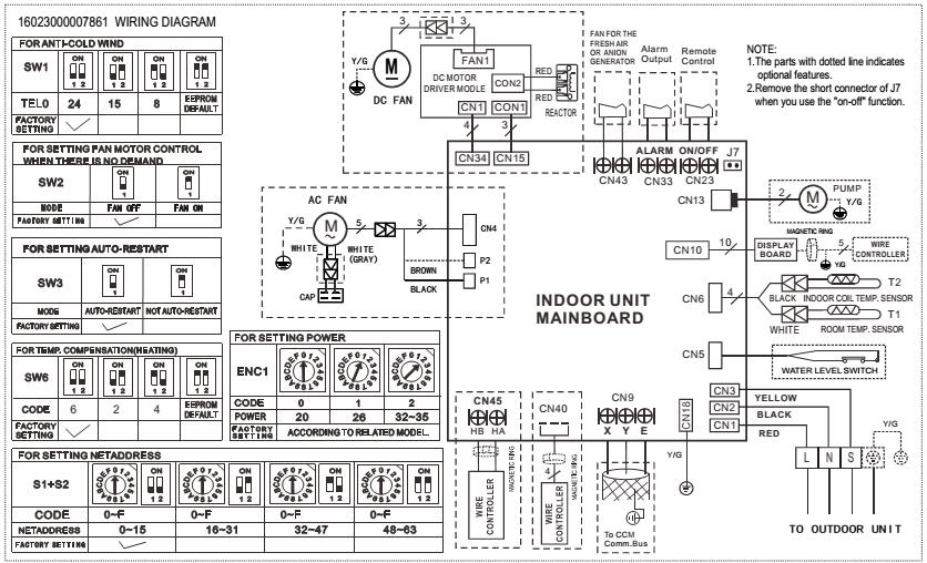
26 5. Wiring diagram 38QUS014DS2*/ 38QUS014DS2-2/ 38QUS018DS2-2 38QUS018DS2* 23
27 38QUS021DS3* 38QUS027DS3* 24
28 38QUS028DS4* 38QUS036DS4* 25
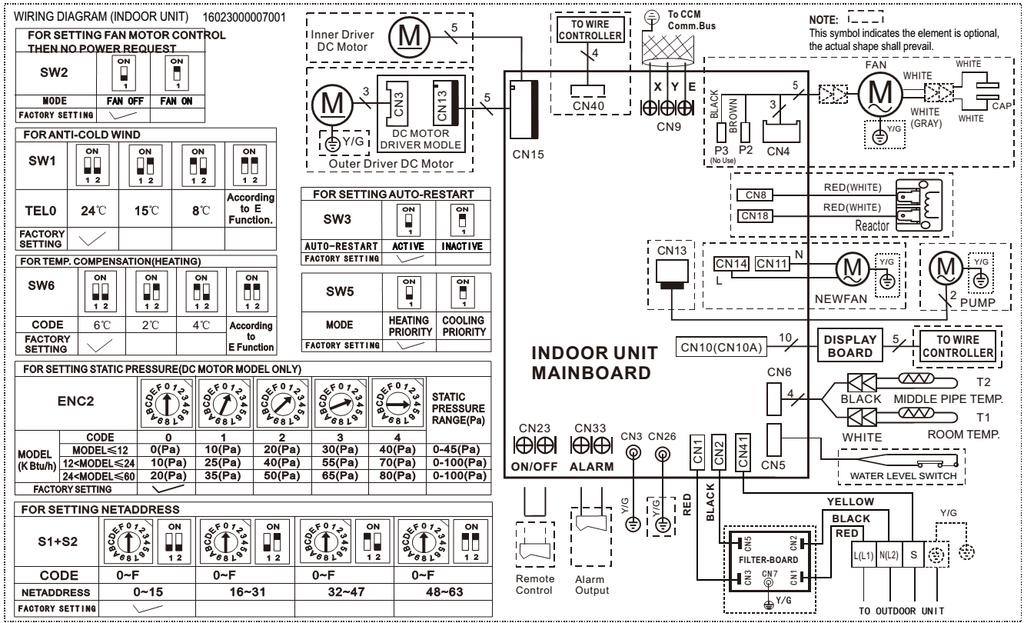
29 38QUS042DS5* 42QHC007D8S 42QHC009D8S 42QHC012D8S 42QHC018D8S 42QHC024D8S A
30 42QTD007D8S/42QTD009D8S/42QTD012D8S/42QTD018D8S 42QTD009DS* 42QTD012DS* 42QTD018DS* 42QTD024DS* 27
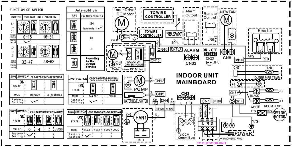
31 42QSS012DS* 42QSS007D8S/42QSS009D8S/42QSS012D8S 28

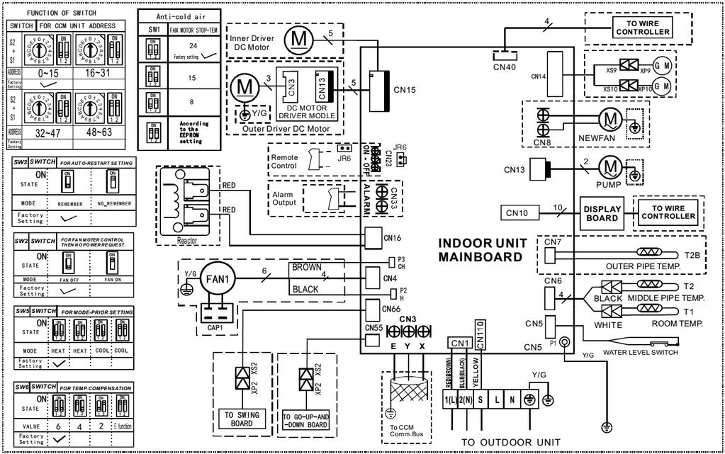
32 42QSS018DS*, 42QSS024DS* 42QZA009DS*, 42QZA012D8S, 42QZA018DS* 29

33 6. Static Pressure (A5 Ducted) 30
34 7. Operation temperature range Temperature Mode Cooling operation Heating operation Drying operation Room temperature 18 ~32 0 ~27 18 ~32 Outdoor temperature 0 ~46-15 ~24 0 ~46 CAUTION: 1. If the air conditioner is used beyond the above conditions, certain safety protection features may come into operation and cause the unit to operate abnormally. 2. The room relative humidity should be less than 80%. If the air conditioner operates beyond this figure, the surface of the air conditioner may attract condensation. Please set the vertical air flow louver to its maximum angle (vertically to the floor), and set HIGH fan mode. 3. The optimum performance will be achieved during this operating temperature zone. 31
35 8. Electronic function te: Below function only for light commercial, for Hi-wall units, please refer to 1 drive 1 service manuals. 8.1 Abbreviation T1: Indoor room temperature T2: Indoor evaporator temperature T2B: Coil temperature of indoor heat exchanger outlet(this sensor is located in outdoor unit) T3: Coil temperature of outdoor heat exchanger T4: Outdoor ambient temperature T5: Compressor discharge temperature Ts: Setting temperature 8.2 Icon explanation on indoor display board Four-way cassette (compact) A5&A6 Duct Timer indicator Operation lamp Temporary button PRE-DEF indicator(cooling and heating type) or fan only indicator(cooling only type) Alarm indicator Infrared signal receiver Display digital tube MANUAL OPERATION TIMER DEF./FAN ALARM Console 32


36 8.2.4 Super slim cassette Ceiling& floor C 8.3 Main Protection Three minutes delay at restart for compressor Sensor protection at open circuit and breaking disconnection Indoor fan delayed open function 33
37 ----When system starts up, the louver will be active immediately, and the indoor fan will open after certain time. ----If the system runs in heating mode, the anti-cold wind function has priority Fan speed is out of control (For the units used DC fan motor) For console: When indoor fan speed keeps too low (300RPM) for certain time, the unit will stop and the LED will display the failure. For other models: When indoor fan speed keeps too low (lower than 300 RPM) for 50s, the indoor fan will shut off and restart 30s later, if protection happened 3 times when fan motor restart continuously, the unit will stop and the LED will display the failure Inverter module protection The Inverter module has a protection function about current, voltage and temperature. If these protections happen, the corresponding code will display on indoor unit and the unit will stop working. 8.4 Operation Modes and Functions Fan-only mode (1) Outdoor fan and compressor stop. (2) For Console: Indoor fan can be set to high/med/low/breeze, for other models: Indoor fan can be set to high/med/low/auto. (3) The louver operates same as in cooling mode. (4) Auto fan in fan-only mode acts as follow: For all models: T H a b c d e (H -L )* L (H -L )* L (H -L )* L L Cooling mode Outdoor fan running rules 34
38 T4 A+ A B C D E F G H I While A,B,C means different fan speed of outdoor unit Indoor fan running rules For all models: In cooling mode, indoor fan runs all the time and the speed can be selected as high, medium, low and auto. When the compressor is running, the indoor fan is controlled as below: Setting fan speed H M L T1-Td ( F) A B C D E F G H I Actual fan speed H+(H+=H+G) H(=H) H-(H-=H-G) M+(M+=M+Z) M(M=M) M-(M-=M-Z) L+(L+=L+D) L(L=L) L-(L-=L-D) The auto fan acts as below rules: T 1 -T d H a b c d (H -L )* L (H -L )* L (H -L )* L L e Evaporator low temperature T2 protection For all models: When T2<4 for 250s or T2<0, the indoor has no capacity demand and resume till T2>8 35
39 8.4.3 Dry mode Indoor fan speed is fixed at breeze and can t be changed. The louver angle is the same as in cooling mode Low indoor room temperature protection In drying mode, if room temperature is lower than 10, the indoor fan will stop and not resume until room temperature exceeds Evaporator anti-freezing protection and condenser high temperature protection are active and the same as that in cooling mode The outdoor fan operates the same as in cooling mode Heating mode Outdoor fan running rules T4 E D C B A A Indoor fan running rules For all models: In heating mode, indoor fan can be selected as high, medium, low and auto. The anti-cold- wind function has the priority. When the compressor is running, the indoor fan is controlled as below: Setting fan speed H M T1-Td Actual fan speed H-(H-=H-G) H(=H) H+(H+=H+G) M-(M-=M-Z) M(M=M) M+(M+=M+Z) L L-(L-=L-D) L(L=L) L+(L+=L+D) - If the compressor stops caused by the room temperature rising, the indoor fan will be forced to run 127 seconds with breeze. During this period, the anti-cold-wind is disabled. 36
40 Auto fan action in heating mode: T 1 -T d L (H + -L )*0.2 + L (H + -L )*0.4 + L (H + -L )*0.6 + L (H + -L )*0.6 + L (H + -L )*0.8 + L H High evaporator coil temp.t2 protection: If T2>63, the indoor unit has no capacity demand and resume till Prevent Over-Heating In heating mode, when the indoor unit has no capacity requirement due to indoor room temperature increased, the Indoor fan will run in super breeze. (Anti-cold wind function has the priority) Defrosting mode: Condition of defrosting: AC will enter the defrosting mode according to the value of temp. of T3 and the value range of temp. change of T3 and also the compressor running time. Condition of ending defrosting: If any one of the following items is satisfied, the defrosting will finish and the machine will turn to normal heating mode. ----T3 rises to be higher than TCDE T3 keeps to be higher than TCDE2 for 80 seconds. ----The machine has run for 10 minutes in defrosting mode. Defrosting action: 37
41 4 -W a y v a lv e n o lo n g e r th a n 1 0 m in C o m p re s s o r C o o l-f9 In d o o r fa n 10S 30S T im e A 10S A n ti c o ld w in d O u td o o r fa n P M V ru n n in g P M V 4 m in s w ith 480P 480P Auto-mode This mode can be chosen by remote controller and the setting temperature can be changed between 17~30. In auto mode, the machine will choose cooling, heating or fan-only mode according to the difference between T1 and TS. For all models: T1-TS Running mode T1-TS>2 Cooling -2< T1-TS 2 Fan-only T1-TS -2 Heating Indoor fan will run at auto fan of the relevant mode. The louver operates same as in relevant mode. If the machine switches mode between heating and cooling, the compressor will keep stopping for 15 minutes and then choose mode according to T1-Ts. If the setting temperature is modified, the machine will choose running function again Forced operation function Enter forced operation function: Press the touch button continually, the AC will run as below sequence: Forced auto Forced cooling Off When the machine is off, pressing the touch button will carry the machine to forced auto mode, after this, if pressing the button once again, the machine will turn into forced cooling mode. In forced cooling mode, pressing touch button will turn off the machine In forced operation mode, all general protections and remote control are available Operation rules: 38
42 Forced cooling mode: The compressor runs at F2 frequency and indoor fan runs as breeze. After running for 30 minutes. the machine will turn to auto mode as 24 setting temperature. Forced auto mode: The action of forced auto mode is the same as normal auto mode with 24 setting temperature When there s indoor unit running in forced cooling, it is the master forced cooling unit. Other indoor units will run at forced cooling mode too and they will be the slave forced cooling units. The slave forced cooling units can not quit forced cooling mode until the master forced cooling unit quit, and turn to cooling mode at low speed with 24 setting temperature The slave forced cooling units will not be controlled by other signals Timer Function Timing range is 24 hours Timer on. The machine will turn on automatically when reaching the setting time Timer off. The machine will turn off automatically when reaching the setting time Timer on/off. The machine will turn on automatically when reaching the setting on time, and then turn off automatically when reaching the setting off time Timer off/on. The machine will turn off automatically when reaching the setting off time, and then turn on automatically when reaching the setting on time The timer function will not change the AC current operation mode. Suppose AC is off now, it will not start up firstly after setting the timer off function. And when reaching the setting time, the timer LED will be off and the AC running mode has not been changed The setting time is relative time Sleep mode The sleep function is available in cooling, heating or auto mode Operation process in sleep mode is as follow. After pressing ECONOMIC or SLEEP button on controller, the machine will turn into sleep mode. When cooling, The set temperature rise 1 per hour(be lower than 30 ). Two hours later, the set temperature will maintain as a constant and the fan speed is kept at low speed. When heating, The set temperature decrease 1 per hour(be higher than 17 ). Two hours later, the set temperature will maintain as a constant and the fan speed is kept at low speed (Anti-cold function takes precedence over all). When auto, After an hour running under economic mode,if it is under cooling mode the set temp will rise 1, if it is under heating mode the set temp will decrease 1, if it is under fan-only mode the set temp will be changeless; the condition will be the same after the air conditioner running under economic mode after 2 hours, and during the next time the set temp do not change Operation time in sleep mode is 7 hours. After 7 hours the AC quits this mode and the AC will turn off. 39
43 Timer off and remote controller off signals have the priority compared with sleep function Auto-Restart function The indoor unit is equipped with auto-restart function, which is carried out through an auto-restart module. In case of a sudden power failure, the module memorizes the setting conditions before the power failure. The unit will resume the previous operation setting (not including swing function) automatically after 3 minutes when power returns. If the memorization condition is forced cooling mode, the unit will run in cooling mode for 30 minutes and turn to auto mode as 24 setting temp. If AC is off before power off and AC is required to start up now, the compressor will have 1 minute delay when power on. Other conditions, the compressor will have 3 minutes delay when restarts Drain pump control (For A5 Duct & Cassette) Adopt the water-level switch to control the action of drain pump. Main action under different condition :( every 5 seconds the system will check the water level one time) 1. When the A/C operates with cooling (including auto cooling) and forced cooling mode or dry mode, the pump will start running immediately and continuously, till stop cooling or dry or no capacity demand. 2. Once the water level increase and up to the control point, LED will alarm and the drain pump open and continue checking the water level. If the water level falls down below the control point (drain pump delay close 1 minute) and operate with the last mode. Otherwise the entire system stop operating (including the pump) and LED remain alarming after 3 minutes, Follow me (optional) 1) If the indoor PCB receives the signal which results from pressing the FOLLOW ME button on remote controller, the buzzer will emit a sound and this indicates the follow me function is initiated. But when the indoor PCB receives signal which sent from remote controller every 3 minutes, the buzzer will not respond. When the unit is running with follow-me function, the PCB will control the unit according to the temperature from follow-me signal, and the temperature collection function of room temperature sensor will be shielded, and the error detective function of room temperature sensor will be still invalid. 2) When the follow-me function is available, the PCB will not respond according to the setting temperature from follow-me signal every 3 minutes. 3) The PCB will take action to the mode change information from remote controller signal, and the follow-me function will be turned off. (if the wired remote controller does not initiate follow me function). 4) When the unit is running with follow-me function, if the PCB doesn t receive any signal from remote controller for 7 minutes or pressing FOLLOW ME button again, the follow-me function will be turned off automatically, and the temperature collection function of room temperature sensor will be available, the PCB will control the unit according to the room temperature detected from its own room temperature sensor and setting temperature. 5) When the indoor PCB receives the follow-me signal from wired remote controller, the control is the 40
44 same as that from wireless remote controller, but buzzer will not emit a sound. When the PCB receives turning-off follow-me signal from wired remote controller, the unit will quit follow-me function at once. The follow-me function controlled by wired remote controller prevails that by wireless remote controller Mode conflict The indoor units can not work cooling mode and heating at same time. Heating mode has a priority. (1) Definition Cooling mode Heating Mode Fan Off Cooling mode Heating Mode Fan Off : mode conflict; : Mode conflict (2) Unit action In case of one Indoor unit working in cooling mode or fan mode, and another indoor unit is set to heating mode, the indoor unit working in cooling mode or fan mode will change to off. The outdoor unit will change to heating mode after compressor stop 3 minutes.. In case of one Indoor unit working in heating mode, and another indoor unit is set to cooling mode or fan mode, the indoor unit setting to cooling mode or fan mode will change to stand by. The outdoor unit will continue working in heating mode. If heating mode stops (not including the indoor unit in heating mode reaching the set temperature), 3 minutes after the outdoor unit restarts and works in cooling mode or fan-only mode. 41
45 9. General information of Outdoor Units Model name Dimension (mm) Compressor 38QUS014DS2* 800x333x554 ASN108D22UEZ 38QUS014DS x333x554 ASN140D21UFZ 38QUS018DS2* 845x363x702 ASM135D23UFZ 38QUS018DS x333x554 ASM135D23UFZ 38QUS021DS3* 845x363x702 ASM135D23UFZ 38QUS027DS3* 845x363x702 ATF235D22UMT 38QUS028DS4* 946x410x810 ATF235D22UMT 38QUS036DS4* 946x410x810 ATF310D43UMT 38QUS042DS5* 946x410x810 ATF310D43UMT 42
46 10. Features Outdoor unit Power relay control Low noise air flow system Hydrophilic aluminum fin The hydrophilic fin can improve the heating efficiency at operation mode. 4 way valve control It is only operated in the heating operation mode except defrosting operation. Anti-rust cabinet Valve protection cover It protects the valves and prevents water from dripping. Discharge pipe temperature protection 43

47 11. Dimensions Model 38QUS014DS2-2 38QUS018DS2-2 Unit:mm W D H W1 A B QUS021DS3* QUS027DS3* QUS028DS4* 38QUS036DS4* QUS042DS5*
48 12. Refrigeration Cycle Diagram 12.1 Refrigeration circuit drawing of inverter 1 drive 2 type IN D O O R O U T D O O R LIQ U ID VA LVE A E X V A C A P IL L A R Y A C H E C K V A L V E LIQ U ID VA LVE B E X V B C A P IL L A R Y B C A P IL L A R Y T U B E T3 C o n d e n s e r te m p. s e n s o r H E A T E X C H A N G E (E V A P O R A T O R ) T 1 R o o m te m p. s e n s o r T 4 A m b ie n t te m p. s e n s o r H E A T E X C H A N G E (C O N D E N S E R ) T 2 B -A E v a p o ra to r T2 E vaporator te m p. s e n s o r G A S V A L V E A te m p. s e n s o r o u tle t m id d le G A S V A L V E B T 2 B -B 4 -W A Y V A L V E A c c u m u la to r C o m p re s s o r T5 D ischarge te m p. s e n s o r C O O L IN G H E A T IN G 12.2 Refrigeration circuit drawing of inverter 1 drive 3 type IN D O O R O U T D O O R L IQ U ID V A L V E A E X V A C A P IL L A R Y A L IQ U ID V A L V E B E X V B C A P IL L A R Y B C H E C K V A L V E L IQ U ID V A L V E C E X V C C A P IL L A R Y C C A P IL L A R Y T U B E T3 C o n d e n s e r te m p. s e n s o r H E A T E X C H A N G E (E V A P O R A T O R ) T 1 R o o m te m p. s e n s o r T 4 A m b ie n t te m p. s e n s o r H E A T E X C H A N G E (C O N D E N S E R ) T2B -A E v a p o ra to r T2 E vaporator G A S V A L V E A te m p. s e n s o r o u tle t te m p. s e n s o r m id d le G A S V A L V E B T 2 B -B 4 -W A Y V A L V E G A S V A L V E C T 2 B -C A c c u m u la to r C o m p re s s o r T 5 D is c h a rg e te m p. s e n s o r C O O L IN G H E A T IN G 45
49 12.3 Refrigeration circuit drawing of inverter 1 drive 4 type IN D O O R O U T D O O R L IQ U ID V A L V E A E X V A C A P IL L A R Y A L IQ U ID V A L V E B E X V B C A P IL L A R Y B C H E C K V A L V E LIQ U ID VA LVE C LIQ U ID VA LVE D E X V C C A P IL L A R Y C E X V D C A P IL L A R Y D C A P IL L A R Y T U B E T3 C o n d e n s e r te m p. s e n s o r H E A T E X C H A N G E (E V A P O R A T O R ) T 1 R o o m te m p. s e n s o r T 4 A m b ie n t te m p. s e n s o r H E A T E X C H A N G E (C O N D E N S E R ) G A S V A L V E A T 2 B -A E v a p o ra to r te m p. s e n s o r o u tle t T 2 E v a p o ra to r te m p. s e n s o r m id d le G A S V A L V E B G A S V A L V E C G A S V A L V E D T 2 B -B T 2 B -C T 2 B -D A c c u m u la to r L o w p re s s u re s w itc h C o m p re s s o r 4 -W A Y V A L V E H ig h p re s s u re s w itc h T 5 D is c h a rg e te m p. s e n s o r C O O L IN G H E A T IN G 12.4 Refrigeration circuit drawing of inverter 1 drive 5 type IN D O O R O U T D O O R L IQ U ID V A L V E A E X V A C A P IL L A R Y A L IQ U ID V A L V E B E X V B C A P IL L A R Y B L IQ U ID V A L V E C E X V C C A P IL L A R Y C C H E C K V A L V E L IQ U ID V A L V E D E X V D C A P IL L A R Y D C A P IL L A R Y T U B E T3 C o n d e n s e r te m p. s e n s o r L IQ U ID V A L V E E E X V E C A P IL L A R Y E H E A T E X C H A N G E (E V A P O R A T O R ) T 1 R o o m te m p. s e n s o r G A S V A L V E A T2B -A E vaporator te m p. s e n s o r o u tle t T 4 A m b ie n t te m p. s e n s o r H E A T E X C H A N G E (C O N D E N S E R ) T2 E vaporator G A S V A L V E B T 2 B -B te m p. s e n s o r m id d le G A S V A L V E C T 2 B -C 4 -W A Y V A L V E G A S V A L V E D G A S V A L V E E T 2 B -D T 2 B -E A c c u m u la to r L o w p re s s u re s w itc h C o m p re s s o r H ig h p re s s u re s w itc h T5 D ischarge te m p. s e n s o r C O O L IN G H E A T IN G 46
50 13. Wiring diagram 38QUS014DS2*/38QUS014DS2-2, 38QUS018DS2*/38QUS018DS2-2 47

51 te: S(1)&S(2) are used in other type of models. They don't need to be connected in multi models. 38QUS021DS3* 48
52 38QUS027DS3* 38QUS036DS4* 49
53 38QUS042DS5* 50
54 14. Indoor units combination 14.1 Indoor unit combination for 38QUS014DS2-2 38QUS014DS2-2 One Unit Two Unit Indoor unit combination for 38QUS018DS2* 38QUS018DS2-2 One Unit Two Unit * means two indoor unit shall not operate simultaneously due to performance reduction Indoor unit combination for 38QUS021DS3* 38QUS021DS3-1 One Unit Two Unit Three Unit Indoor unit combination for 38QUS027DS3* 38QUS027DS3-1 One Unit Two Unit Three Unit
55 14.5 Indoor unit combination for 38QUS028DS3* 38QUS028DS4-1 One Unit Two Unit Three Unit Four Unit Indoor unit combination for 38QUS036DS4* 38QUS036DS4-1 One Unit Two Unit Three Unit Four Unit Indoor unit combination for 38QUS042DS5* 38QUS042DS5-1 One Unit Two Unit Three Unit Four Unit Five Unit
56 15 Sound Levels Outdoor Unit Microphone H 1.0m te: H= 0.5 height of outdoor unit Model ise Power db(a) ise level db(a) 38QUS014DS2* QUS014DS QUS018DS2* QUS018DS QUS021DS3* QUS027DS3* QUS028DS4* QUS036DS4* QUS042DS5*
57 16 Installation Details Wrench torque sheet for installation Outside diameter Torque Additional tightening torque mm N.cm N.cm Ф (153kgf.cm) 1600(163kgf.cm) Ф (255kgf.cm) 2600(265kgf.cm) Ф (357kgf.cm) 3600(367kgf.cm) Connecting the cables The power cord of connect should be selected according to the following specifications sheet. Rated current of appliance minal cross-sectional area (mm²) >3 and >6 and 10 1 >10 and >16 and The cable size and the current of the fuse or switch are determined by the maximum current indicated on the nameplate which located on the side panel of the unit. Please refer to the nameplate before selecting the cable, fuse and switch Pipe length and the elevation Maximum piping length and height difference 1 drive 2 1 drive 3 1 drive 4 1 drive 5 Max. length for all rooms (m) Max. length for one IU (m) Max. height difference between IU and OU (m) Max. height difference between IUs (m) Additional refrigerant charge 1 drive 2 1 drive 3 1 drive 4 1 drive 5 Chargeless pipe length (m) Additional refrigerant charge (g) 15 x (length for all rooms - 15) 15 x (length for all rooms 22.5) 15 x (length for all rooms - 30) 15 x (length for all rooms 37.5) Caution: Refrigerant pipe diameter is different according to indoor unit to be connected. When using the extension pipe, refer to the tables below. 54
58 When refrigerant pipe diameter is different from that of outdoor unit union (for 18K&24K indoor unit), additional transfer connector needs to be used on outdoor unit union. Indoor unit Extension pipe diameter (mm/inch) Model 7K9K12K 18K Pipe diameter (mm/inch) Liquid 6.35(1/4) Liquid 6.35(1/4) Gas 9.52(3/8) Gas 9.52(3/8) Liquid 6.35(1/4) Liquid 6.35(1/4) Gas 12.7(1/2) Gas 12.7(1/2) 24K Liquid 9.52(3/8) Liquid 9.52(3/8) Gas 15.9(5/8) Gas 15.9(5/8) Outdoor unit union diameter (mm/inch) Liquid 6.35(1/4) Indoor unit A/B/C/D/E Gas 9.52(3/8) 12.7(1/2) Installation for the first time Air and moisture in the refrigerant system have undesirable effects as below: Pressure in the system rises. Operating current rises. Cooling or heating efficiency drops. Moisture in the refrigerant circuit may freeze and block capillary tubing. Water may lead to corrosion of parts in the refrigerant system. Therefore, the indoor units and the pipes between indoor and outdoor units must be leak tested and evacuated to remove gas and moisture from the system. Gas leak check (Soap water method): Apply soap water or a liquid neutral detergent on the indoor unit connections or outdoor unit connections by a soft brush to check for leakage of the connecting points of the piping. If bubbles come out, the pipes have leakage. 1. Air purging with vacuum pump 55
59 (Indoor unit) (Liquid side) (Outdoor unit) Two-way valve Close (Gas side) Manifold valve Compound meter Pressure gauge -0.1MPa Lo Hi Three-way valve Close Handle Lo Charge hose Handle Hi Charge hose Vacuum pump Vacuum pump 1) Completely tighten the flare nuts of the indoor and outdoor units, confirm that both the 2-way and 3-way valves are set to the closed position. 2) Connect the charge hose with the push pin of handle lo to the 3-way valves gas service port.. 3) Connect the charge hose of handle hi connection to the vacuum pump. 4) Fully open the handle Lo of the manifold valve. 5) Operate the vacuum pump to evacuate. 6) Make evacuation for 30 minutes and check whether the compound meter indicates -0.1Mpa. If the meter does not indicate -0.1Mpa after pumping 30 minutes, it should be pumped 20 minutes more. If the pressure can t achieve -0.1Mpa after pumping 50 minutes, please check if there are some leakage points. Fully close the handle Lo valve of the manifold valve and stop the operation of the vacuum pump. Confirm that the gauge needle does not move (approximately 5 minutes after turning off the vacuum pump). 7) Turn the flare nut of the 3-way valves about 45 counterclockwise for 6 or 7seconds after the gas coming out, then tighten the flare nut again. Make sure the pressure display in the pressure indicator is a little higher than the atmosphere pressure. Then remove the charge hose from the 3 way valve. 8) Fully open the 2 way valve and 3 way valve and securely tighten the cap of the 3 way valve. 56
60 2. Adding the refrigerant if the pipe length >5m Electronic scale Procedure: 1). Connect the charge hose to the charging cylinder, open the 2-way valve and the 3-way valve. Connect the charge hose which you disconnected from the vacuum pump to the valve at the bottom of the cylinder. If the refrigerant is R410A, make the cylinder bottom up to ensure the liquid charge. 2). Purge the air from the charge hose. Open the valve at the bottom of the cylinder and press the check valve on the charge set to purge the air (be careful of the liquid refrigerant). 3) Put the charging cylinder onto the electronic scale and record the weight. 4) Operate the air conditioner at the cooling mode. 5) Open the valves (Low side) on the charge set and charge the system with liquid refrigerant. 6).When the electronic scale displays the proper weight (refer to the table), disconnect the charge hose from the 3-way valve s service port immediately and turn off the air conditioner before disconnecting the hose. 7). Mount the valve stem caps and the service port Use torque wrench to tighten the service port cap to a torque of 18N.m. Be sure to check for gas leakage. 57
61 Adding the refrigerant after running the system for many years Electronic scale Procedure: 1). Connect the charge hose to the 3-way service port, open the 2-way valve and the 3-way valve. Connect the charge hose to the valve at the bottom of the cylinder. If the refrigerant is R410A, make the cylinder bottom up to ensure liquid charge. 2). Purge the air from the charge hose. Open the valve at the bottom of the cylinder and press the check valve on the charge set to purge the air (be careful of the liquid refrigerant). 3) Put the charging cylinder onto the electronic scale and record the weight. 4) Operate the air conditioner at the cooling mode. 5) Open the valves (Low side) on the charge set and charge the system with liquid refrigerant. 6).When the electronic scale displays the proper weight (refer to the gauge and the pressure of the low side), disconnect the charge hose from the 3-way valve s service port immediately and turn off the air conditioner before disconnecting the hose. 7). Mount the valve stem caps and the service port Use torque wrench to tighten the service port cap to a torque of 18N.m. Be sure to check for gas leakage. 58
62 Re-installation while the indoor unit need to be repaired 1. Collecting the refrigerant into the outdoor unit Procedure 1). Confirm that both the 2-way and 3-way valves are set to the opened position Remove the valve stem caps and confirm that the valve stems are in the opened position. Be sure to use a hexagonal wrench to operate the valve stems. 2). Connect the charge hose with the push pin of handle lo to the 3-way valves gas service port. 3). Air purging of the charge hose. Open the handle Lo valve of the manifold valve slightly to purge air from the charge hose for 5 seconds and then close it quickly. 4). Set the 2-way valve to the close position. 5). Operate the air conditioner at the cooling cycle and stop it when the gauge indicates 0.1MPa. 6). Set the 3-way valve to the closed position immediately Do this quickly so that the gauge ends up indicating 0.3 to 0.5Mpa. Disconnect the charge set, and tighten the 2-way and 3-way valve s stem nuts. Use a torque wrench to tighten the 3-way valves service port cap to a torque of 1.8 kgf.m. Be sure to check for gas leakage. 59
63 Re-installation while the outdoor unit need to be repaired 1. Evacuation for the whole system Procedure: 1). Confirm that both the 2-way and 3-way valves are set to the opened position. 2). Connect the vacuum pump to 3-way valve s service port. 3). Evacuation for approximately one hour. Confirm that the compound meter indicates -0.1Mpa. 4). Close the valve (Low side) on the charge set, turn off the vacuum pump, and confirm that the gauge needle does not move (approximately 5 minutes after turning off the vacuum pump). 5). Disconnect the charge hose from the vacuum pump. 60
64 2. Refrigerant charging Procedure: 1). Connect the charge hose to the charging cylinder, open the 2-way valve and the 3-way valve Connect the charge hose which you disconnected from the vacuum pump to the valve at the bottom of the cylinder. If the refrigerant is R410A, make the cylinder bottom up to ensure liquid charge. 2). Purge the air from the charge hose Open the valve at the bottom of the cylinder and press the check valve on the charge set to purge the air (be careful of the liquid refrigerant). 3) Put the charging cylinder onto the electronic scale and record the weight. 4). Open the valves (Low side) on the charge set and charge the system with liquid refrigerant If the system cannot be charge with the specified amount of refrigerant, or can be charged with a little at a time (approximately 150g each time), operating the air conditioner in the cooling cycle; however, one time is not sufficient, wait approximately 1 minute and then repeat the procedure. 5).When the electronic scale displays the proper weight, disconnect the charge hose from the 3-way valve s service port immediately If the system has been charged with liquid refrigerant while operating the air conditioner, turn off the air conditioner before disconnecting the hose. 6). Mounted the valve stem caps and the service port Use torque wrench to tighten the service port cap to a torque of 18N.m. Be sure to check for gas leakage 61
65 17 Electronic control function 17.1 Abbreviation T1: Indoor ambient temperature T2: Coil temperature of indoor heat exchanger middle. T2B: Coil temperature of indoor heat exchanger outlet(this sensor is located in outdoor unit) T3: Coil temperature of outdoor heat exchanger T4: Outdoor ambient temperature T5: Compressor discharge temperature Ts: Setting temperature 17.2 Electric control working environment Input voltage: 198V~264V Input power frequency:50hz Indoor fan normal working amp. is less than 1A Outdoor fan. normal working amp. is less than 1.5A Four-way valve normal working amp. is less than 1A Outdoor unit s digital display tube There is a digital display tube in outdoor PCB. Digital display tube display function In standby, the LED displays - - In compressor operation, the LED display the running frequency, In defrosting mode, The LED displays df or alternative displays between running frequency and df (each displays 0.5s) In compressor pre-heating, The LED displays PH or alternative displays between running frequency and PH (each displays 0.5s) During the oil return process, The LED displays RO or alternative displays between running frequency and RO (each displays 0.5s) In low ambient cooling mode, the LED displays LC or alternative displays between running frequency and LC (each displays 0.5s) In forced cooling mode, the LED displays FC or alternative displays between running frequency and FC (each displays 0.5s) When PFC module protection occurs three times within 15 minutes, the LED displays E6 or alternative displays between running frequency and E6 (each displays 0.5s) In protection or malfunction, the LED displays error code or protection code. 62
66 17.4 Outdoor unit point check function There is a check switch in outdoor PCB. Press the switch N times it will display the content corresponding to. N. After getting into the check function, it will display. N with 1.5s, meanwhile the low bit decimal of digit display flashing, indicated to get into the check function display. After 1.5s, it will display the content corresponding to. N. the digital display tube will display the follow procedure when push SW1 each time. Display Remark 0 rmal display Display running frequency, running state or malfunction code 1. of indoor units in good connection Actual data 2 Outdoor unit running mode code Standby:0,Fan only 1, Cooling:2, Heating:3, Forced cooling:4 Forced defrosting:5 3 A indoor unit capacity 4 B indoor unit capacity 5 C indoor unit capacity 6 D indoor unit capacity 7 E indoor unit capacity 8 A Indoor unit capacity demand code 9 B Indoor unit capacity demand code 10 C Indoor unit capacity demand code 11 D Indoor unit capacity demand code 12 E Indoor unit capacity demand code 13 Total indoor units amendatory capacity demand code 14 The frequency corresponding to the total indoor units amendatory capacity demand 15 The frequency after the frequency limit 16 The frequency sending to compressor control chip 17 A indoor unit evaporator outlet temp.(t 2BA) 18 B indoor unit evaporator outlet temp.(t 2BB) 19 C indoor unit evaporator outlet temp.(t 2BC) 20 D indoor unit evaporator outlet temp.(t 2BD) 21 E indoor unit evaporator outlet temp.(t 2BE) The capacity unit is horse power. If the indoor unit is not connected, the digital display tube will show: (7K:0.8HP, 9K:1HP,12K:1.2HP,18K:1.5HP) rm value*hp (7K:0.8HP, 9K:1HP,12K:1.2HP,18K:1.5HP) If the temp. is lower than -9 degree, the digital display tube will show -9.If the temp. is higher than 70 degree, the digital display tube will show 70. If the indoor unit is not connected, the digital display tube will show: 22 A indoor unit room temp.(t 1A) If the temp. is lower than 0 degree, the digital display tube will show 23 B indoor unit room temp.(t 1B) 0.If the temp. is higher than 70 degree, the digital display tube will show 70. If the indoor unit is not connected, the digital display tube 24 C indoor unit room temp.(t 1C) will show: 25 D indoor unit room temp.(t 1D) 26 E indoor unit room temp.(t 1E) 27 A indoor unit evaporator temp.(t 2A) 28 B indoor unit evaporator temp.(t 2B) 29 C indoor unit evaporator temp.(t 2C) 30 D indoor unit evaporator temp.(t 2D) 31 E indoor unit evaporator temp.(t 2E) 32 Condenser pipe temp.(t3) 33 Outdoor ambient temp.(t4) If the temp. is lower than -9 degree, the digital display tube will show -9.If the temp. is higher than 70 degree, the digital display tube will show 70. If the indoor unit is not connected, the digital display tube will show: 34 Compressor discharge temp.(t5) The display value is between 30~129 degree. If the temp. is lower than 30 degree, the digital display tube will show 30.If the temp. is higher than 99 degree, the digital display tube will show single digit and tens digit. For example, the digital display tube show 0.5,it means the compressor discharge temp. is 105 degree.) 35 AD value of current The display value is hex number. 63
67 36 AD value of voltage For example,the digital display tube show Cd, it means AD value is EXV open angle for A indoor unit 38 EXV open angle for B indoor unit 39 EXV open angle for C indoor unit 40 EXV open angle for D indoor unit 41 EXV open angle for E indoor unit 42 Frequency limit symbol Actual data/4. If the value is higher than 99, the digital display tube will show single digit and tens digit. For example,the digital display tube show 2.0,it means the EXV open angle is 120 4=480p.) Bit7 Bit6 Frequency limit caused by IGBT radiator Frequency limit caused by PFC Bit5 Frequency limit caused by T4. Bit4 Frequency limit caused by T2. Bit3 Frequency limit caused by T3. Bit2 Frequency limit caused by T5. Bit1 Bit0 Frequency limit caused by current Frequency limit caused by voltage The display value is hex number. For example, the digital display tube show 2A,then Bit5=1, Bit3=1, Bit1=1. It means frequency limit caused by T4,T3 and current. 43 Average value of T2 (Sum T2 value of all indoor units)/( number of indoor units in good connection)(cooling:t2b, heating:t2) 44 Outdoor unit fan motor state Fan off:0, High speed:1, Med speed:2, Low speed:3 Breeze:4, Super breeze:5 45 The last error or protection code 00 means no malfunction and protection 17.5 Protection Three minutes delay at restart for compressor Temperature protection of compressor discharge. When the compressor discharge temp. is getting higher, the running frequency will be limited as below rules: T5 C o m p re s s o r o ff F re q u e n c y lim it F re q u e n c y h o ld in g N o rm a l Low voltage protection V O L T A G E N o lim it V O L T _ L T M _ F R E Q 1 _ A D D V O L T _ L T M _ F R E Q 2 _ A D D te: if the low voltage protection occurs and not resumes within 3min, it will keep the protection always after restart the machine. 64
68 Compressor current limit protection Temperature interval.of current limit is same as range of T4 limited frequency. Cooling mode: T4 C o o lz o n e 5 C o o lz o n e 4 C o o lz o n e 3 Heating mode: C o o lz o n e 2 C o o lz o n e 1 T4 H e a tz o n e 4 H e a tz o n e 3 H e a tz o n e 2 H e a tz o n e Indoor / outdoor units communication protection If the indoor units cannot receive the feedback signal from the outdoor units for 2 minutes, the AC will stop and display the failure High condenser coil temp. protection. T3 O ff D e c re a s e H o ld R e s u m e Outdoor unit anti-freezing protection When T2<4 for 250 seconds or T2<0, the indoor unit capacity demand will be zero and resume to normal when T2>8 and the time of protection is no less than 3 minutes Oil return Running rules: 1. If the compressor frequency keeps lower than setting frequency for setting time, the AC will rise the frequency to setting frequency for setting time and then resume to former frequency. 2. The EXV will keep 300p while the indoor units will keep the current running mode. 65
69 If the outdoor ambient is higher than setting frequency during the oil return, the AC quit oil return Low outdoor ambient temperature protection When compressor is off, T4 is be lower than -35.for 10s, the AC will stop and display LP. When compressor is on, T4 is be lower than -40.for 10s, the AC will stop and display LP. When T4 is no lower than -32.for 10s, the unit will exit protection. 66
70 18 Troubleshooting 18.1 Indoor unit error code explanation: For Console Malfunction Timer Lamp Operation Lamp (flashes) Indoor EEPROM malfunction X 1 Communication malfunction between indoor and outdoor units X 2 Indoor fan speed has been out of control X 4 Open or short circuit of T1 temperature sensor X 5 Open or short circuit of T2 temperature sensor X 6 Overcurrent protection (For some units) O 1 Open or short circuit of T4 temperature sensor O 2 Open or short circuit of T3 temperature sensor O 3 Open or short circuit of T5 temperature sensor O 4 Outdoor EEPROM malfunction (For some units) O 5 Outdoor fan speed is out of control O 6 Open or short circuit of T2B temperature sensor (For free-match indoor units) O 7 IPM module malfunction 1 Over voltage or over low voltage protection 2 Too low ambient temperature protection 4 Inverter compressor drive protection 5 Mode conflict 6 Low pressure protection of compressor 7 O (on) X(off) (flash at 2Hz) For other type Malfunction Error Code Timer Lamp Operation Lamp (flashes) Indoor EEPROM malfunction E0 X 1 Communication malfunction between indoor and outdoor units E1 X 2 Indoor fan speed has been out of control E3 X 4 Open or short circuit of T1 temperature sensor E4 X 5 Open or short circuit of T2 temperature sensor E5 X 6 Water level alarm EE X 8 Overcurrent protection (For some units) F0 O 1 Open or short circuit of T4 temperature sensor F1 O 2 Open or short circuit of T3 temperature sensor F2 O 3 Open or short circuit of T5 temperature sensor F3 O 4 Outdoor EEPROM malfunction (For some units) F4 O 5 Outdoor fan speed is out of control F5 O 6 Open or short circuit of T2B temperature sensor (For free-match indoor units) F6 O 7 Communication error between auto-lifting panel and slim cassette (For F7 O 8 67
71 slim cassette with auto-lifting panel) Auto-lifting panel is faulty (For slim cassette with auto-lifting panel) F8 O 9 Auto-lifting panel is not closed (For slim cassette with auto-lifting panel) F9 O 10 IPM module malfunction P0 1 Over voltage or over low voltage protection P1 2 Too low ambient temperature protection P3 4 Error rotor position protection of compressor P4 5 Mode conflict P5 6 Low pressure protection of compressor P6 7 O (on) X(off) (flash at 2Hz) 18.2 Outdoor unit error code explanation: Display LED STATUS E0 E2 E3 E4 E5 E8 F1 F2 F3 F4 F5 P1 P2 P3 P4 P5 P6 LP Outdoor EEPROM malfunction Indoor / outdoor units communication error Communication malfunction between IPM board and outdoor main board Open or short circuit of outdoor unit temperature sensor Voltage protection Outdoor fan speed has been out of control A Indoor unit coil outlet temperature sensor or connector of sensor is defective B Indoor unit coil outlet temperature sensor or connector of sensor is defective C Indoor unit coil outlet temperature sensor or connector of sensor is defective D Indoor unit coil outlet temperature sensor or connector of sensor is defective E Indoor unit coil outlet temperature sensor or connector of sensor is defective High pressure protection (ForM4OE-28HFN1-Q, 38QUS036DS4*, 38QUS042DS5*) Low pressure protection (ForM4OE-28HFN1-Q, 38QUS036DS4*, 38QUS042DS5*) Current protection of compressor Temperature protection of compressor discharge High temperature protection of condenser IPM module protection Low ambient temperature protection te: Once these error codes display, they will disappear in at least 30 seconds if the unit come back to normal.(except E2&E3) 68
72 18.3 Trouble shooting For the indoor unit Indoor EEPROM malfunction Power off, then restart the unit 2 minutes later Replace the indoor main PCB EEPROM: An electrically erasable programmable read-only memory whose contents can be erased and reprogrammed using a pulsed voltage. 69
73 Indoor / outdoor units communication error Indoor / outdoor units communication error Start: Power off, then Power on the A/C by the Breaker. (reconnect the power wire). Is it still displaying the error code? Check wiring on the outdoor and indoor terminal follow the wiring diagram. Is all connecting correctly? Reconnect the wiring Reconnect the wiring Turn on all indoor unit by remote controller. Is all indoor unit display Measure Vs, is it moving alternately between positive value and negative value? (Vs is the voltage between S and N). Refer PIC 1 A: Is all the wiring between terminal and Indoor PCB connect ok? Replace the Indoor PCB Turn off the all indoor units. Is IPM power LED or operating LED lamp On? Refer PIC2 Replace IPM board or the outdoor main PCB Power on by remote controller, IIs it still displaying the error code after 3 minutes? Is main board lamp on? Refer PIC 3. Is the reactor connecting well? Reconnect the wiring Replace the outdoor main PCB Is indoor units number correct? Check on the outdoor check point. (2 for dual zone, 3 for tri zone, 4 for qua zone,5 for qui zone). Refer PIC 4. Trouble is solved first time second time A Replacee outdoor unit PCB assembly(include wiring) totally 70
, is it moving alternately")


74 Pic 1: check the voltage of N to S (Vs), is it moving alternately between positive value and negative value? Pic 2: IPM or outdoor main PCB Operating Self-Check Pic 2: IPM or outdoor main PCB Power, Self-Check Operating 71

75 PIC3 : Main board LED when power on and unit standby.. PIC 4: check point button, Press 1 time for check how many indoor units are connected 72
76 indoor unit fan speed has been out of control Power off, then restart the unit 2 minutes later. Is it still displaying the error code? The unit operates normally. Shut off the power supply, rotate the fan by hand. Does it rotate properly? Find out the cause and have it solved. For example, whether the fan is blocked or the screws which fix the fan are tighten. Check the wiring of fan motor. Are all the connections good? Correct the connections. Check whether the main PCB is normal through index 1? Replace the main PCB Replace the fan motor Index 1: 1: Indoor AC fan motor Power on and set the unit running in fan mode at high fan speed. After running for 15 seconds, measure the voltage of pin1 and pin2. If the value of the voltage is less than 100V(208~240V power supply)or 50V(115V power supply), the PCB must have problems and need to be replaced. 2. Indoor DC fan motor(control chip is inside fan motor) Power on and when the unit is in standby, measure the voltage of pin1-pin3, pin4-pin3 in fan motor connector. If the value of the voltage is not in the range showing in below table, the PCB must have problems and need to be replaced. For other models: 73
77 For console: DC motor voltage input and output For split type: NO. Color Signal Voltage 1 Red Vs/Vm 280V~380V Black GND 0V 4 White Vcc V 5 Yellow Vsp 0~5.6V 6 Blue FG V For other types: NO. Color Signal Voltage 1 Red Vs/Vm 192V~380V Black GND 0V 4 White Vcc V 5 Yellow Vsp 0~6.5V 6 Blue FG V 74
78 Open or short circuit of temperature sensor. Check the connections between temperature sensor and PCB. Are the connections good? Correct the connections. Measure the resistance value of the sensor via Appendix 1 Is it normal? Replace the sensor. Replace the indoor PCB Full-water malfunction Power off, then restart the unit 2 minutes later. Is it still displaying the error code? If the water-level switch is inserted well? Insert the water-level switch well If the water-level switch is broken? Replace the water-level switch Replace the water pump, If malfunction is still not solved Replace the indoor main PCB 75
79 For the super-slim cassette with up-down panel Communication error between indoor unit and up-down panel F0 Displayed F7 Communication failure between indoor unit and up-down panel Check the wire connection between up-down panel and indoor unit, is it right? Correct the connection Replace the up-down panel Up-down panel is defective Replace the indoor main PCB F1 F8 Displayed Up-down panel is defective If panel can not move slightly, check the wiring of louver motors Retry if panel can up and down normally? Reconnect If panel can move slightly, power off, then restart the unit 2 minutes later. If If the error still exists? Replace the louver motors Check the wiring of left and right sensors Reconnect The up-down panel is defective. replace it 76
80 For the outdoor unit Outdoor EEPROM malfunction(odu E0) Power off, then restart the unit 2 minutes later Replace the outdoor main PCB EEPROM: An electrically erasable programmable read-only memory whose contents can be erased and reprogrammed using a pulsed voltage. 77
81 Communication malfunction between IPM board and outdoor main board(odu E3) E3 display Communication malfunction between IPM board and outdoor main board Is there at least one LED in the IPM board light? Check the signal wire between the IPM board and the main board, is it connected good? Reconnect and retry. Is error still display? Replace IPM board, and then check whether the system can run normally Replace outdoor main board, and then check whether the system can run normally Replace the electric control box Trouble is solved 78
82 Voltage protection(odu E5) Voltage protection Check the voltage of outdoor unit power supply, whether the voltage between L(L1) and N (L2) is about 220~240VAC Check the power supply Check whether the voltage of IPM board P and N is normal? DC V for 18-27KBtu/h; DC V for 36-42KBtu/h Replace bridge rectifiers, and then check whether the system can run normally Replace IPM board, and then check whether the system can run normally Replace outdoor main board Trouble is solved 79
83 Outdoor unit fan speed has been out of control (E8) Power off, then restart the unit 2 minutes later. Is it still displaying the error code? The unit operates normally. Shut off the power supply, rotate the fan by hand. Does it rotate properly? Find out the cause and have it solved. For example, whether the fan is blocked or the screws which fix the fan are tighten. Check the wiring of fan motor. Are all the connections good? Correct the connections. Check whether the main PCB is normal through index 1? Replace the main PCB Replace the fan motor Index 1: 1. Outdoor DC fan motor(control chip is inside fan motor) Power on and when the unit is in standby, measure the voltage of pin1-pin3, pin4-pin3 in fan motor connector. If the value of the voltage is not in the range showing in below table, the PCB must have problems and need to be replaced. DC motor voltage input and output NO. Color Signal Voltage 1 Red Vs/Vm 140V~380V Black GND 0V 4 White Vcc V 5 Yellow Vsp 0~6.5V 6 Blue FG 15V 80
84 High pressure protection (ODU P1)(For 38QUS036DS4*, 38QUS042DS5*) High pressure protection Whether the wiring between the high pressure switch and main control board is connected well or correctly Connect it well Whether the high pressure protector is broken Method: Disconnect the plug. Measure the resistance of the high pressure protector, if the protector is normal the value is o, Replace high pressure protector Check whether the outdoor ambient temperature is higher than 50 Stop the unit Check if the outdoor unit ventilation is good NO Make the outdoor unit ventilate well Check if the outdoor fan runs properly please refer to the solution of fan speed has been out of control malfunction. Find out the cause and have it solved. Check whether the heat exchanger is dirty Clean the heat exchanger Replace outdoor main board Check whether the refrigerant system is ok 81
85 Low pressure protection (ODU P2)(For38QUS036DS4*, 38QUS042DS5*) Low pressure protection Whether the wiring between the low pressure protector and main control board is connected well or correctly Connect it well Whether the low pressure protector is broken Method: Disconnect the plug. Measure the resistance of the low pressure protector. If the protector is normal the value is o Replace low pressure protector Check whether the outdoor ambient temperature is too low Stop the unit Check whether valve core of high pressure valve is opened Check if if the indoor fan runs properly in cooling mode Open fully valve core of high pressure valve please refer to the solution of fan speed has been out of control malfunction. Find out the cause and have it solved. Replace outdoor main board Refrigerant is not enough add the refrigerant Check whether the refrigerant system is ok 82
86 Current protection of compressor (ODU P3) Current protection of compressor Judge 1: Check whether the input current of the power supply wire is higher than max protection current value Check whether the refrigerant system is ok Judge 2: Check whether the outdoor ambient temperature is higher than 50 Stop the unit Judge 3: Check whether the outdoor unit is bad ventilation Make the outdoor unit ventilate well Judge 4: Check whether the heat exchanger is dirty Clean the heat exchanger Judge 5: The refrigerant pipe is blocked Let the refrigerant out, then use the high pressure nitrogen or refrigerant to blow pipe, vacuumize and charge the refrigerant again Replace outdoor main board,and check whether the system can run normally Replace the electric control box Trouble is solved 83
87 Temperature protection of compressor discharge (ODU P4) Temperature protection of compressor discharge Check whether the compressor discharge temp. is more than 115 C? Check whether the refrigerant is leak Stop leaking and add refrigerant Check whether the connection is right between compressor discharge temp. sensor and PCB according to wiring diagrams? Correct the wiring connection Measure the resistance value of compressor discharge temp. sensor. If If the value is not normal is normal refer to the Appendix 2? Replace the compressor discharge temp. sensor Replace outdoor main PCB Replace high pressure valve assy 84
88 High temperature protection of condenser (ODU P5) When outdoor pipe temperature is more than 65 C, the unit will stop, and unit runs again when outdoor pipe temperature less than 52 C. High temperature protection of condenser Check the connection between temperature sensor and PCB. Correct the connection Check whether the condenser temperature is Higher than 65 C Check whether the resistance of condenser temp. sensor is normal refer to the Appendix 1 Replace the temperature sensor Check whether the outdoor ambient temperature is higher than 50 Stop the unit Check if the outdoor unit ventilation is good Make the outdoor unit ventilate well Check if the outdoor fan runs properly please refer to the solution of fan speed has been out of control malfunction. Find out the cause and have it solved. Check whether the heat exchanger is dirty Clean the heat exchanger Replace outdoor main board Refrigerant is not enough add the refrigerant Check whether the refrigerant system is ok 85
89 IPM module protection (ODU P6) IPM module protection Check whether the voltage range of P-N on IPM module is normal? DC V for 18-28KBtu/h; DC V for 36-42KBtu/h Check whether the input power supply is correct? V, 1N, 60Hz Regulate it to correct, then check whether the system can work normally? Check whether the connecting line between main board and the IPM module is connected tightly Connect it tightly, check ok or not? Check whether the power supply line is connected correctly and tightly Connect it correctly and tightly, check ok or not? Check whether the connecting line of the compressor is connected correctly or tightly Connect it well, check ok or not? Check whether the lines in E-part box are connected tightly Connect it tightly, check ok or not? Replace the IPM module, check whether the system can work normally? Check if the outdoor fan runs properly or the outdoor unit ventilation is good. Replace the main board; check whether the system can work normally? Check whether the resistance of the fan motor is normal. If not, replace the fan motor. For other models, refer to the solution of fan speed has been out of control malfunction. F i n d o u t the cause and have it solved. Check whether the bridge rectifiers are normal? Use the multimeter to measure the resistance between each two terminals, check whether there is the condition that value of resistance is 0 Check whether the connecting line of every reactor is normal? If the line is broken, the resistance of the two ports is (models except for M4OA-36HFN1- Q,M4OD-28HFN1-Q, M5OC-36HFN1- Q);Check whether the PFC module broken (for M4OA-36HFN1-Q,M4OD- 28HFN1-Q, M5OC-36HFN1-Q,M50D- 42HFN1-Q) Replace the bridge rectifiers Replace the connecting line or reactor or replace the PFC module(for M4OC-36HRFN1- M,M50D-42HFN1-Q) Replace the compressor, check whether the system can work normally? Trouble is solved 86
90 18.4 Main parts check Spec. Model Indoor unit 9K/12K/18K/24K 9K/12K/18K 9K/12K 18K/24K Cassette Console Ducted DL Indoor fan motor ZKFP ZKFP ZKFN ZKFN Model 24K Cassette 18K/24K Ducted Indoor fan motor ZKFP ZKFN Outdoor unit Model 1x2(14k) 1x2(18k) 1x3(21K) 1x3(27K) Compressor ASN108D22UEZ ASM135D23UFZ ASM135D23UFZ ATF235D22UMT Outdoor fan motor ZKFN L ZKFN L ZKFN ZKFN Model 1x4(28K) 1x4(36K) 1x5(42K) Compressor ATF235D22UMT ATF310D43UMT ATF310D43UMT Outdoor fan motor ZKFN ZKFN ZKFN
91 1. Temperature sensor checking Disconnect the temperature sensor from PCB, measure the resistance value with a tester. Temperature Sensors. Room temp.(t1) sensor, Indoor coil temp.(t2) sensor, Outdoor coil temp.(t3) sensor, Outdoor ambient temp.(t4) sensor, Compressor discharge temp.(t5) sensor. Measure the resistance value of each winding by using the multi-meter. 88
92 Appendix 1 Temperature Sensor Resistance Value Table for T1,T2,T3,T4,T2B ( --K) K Ohm K Ohm K Ohm K Ohm
93 Appendix 2 Temperature Sensor Resistance Value Table for T5 ( --K) K Ohm K Ohm K Ohm K Ohm B(25/50)=3950K R(90 )=5KΩ±3%
 1.")
94 2.Compressor checking Measure the resistance value of each winding by using the tester. Position Resistance Value ASN108D22UEZ ASM135D23UFZ ATF235D22UMT ATF310D43UMT Blue - Red 1.57Ω(20 ) 1.75Ω(20 ) 0.75Ω(20 ) 0.65Ω(20 ) 91
TROUBLESHOOTING. KSIO MINI Split DC Inverter Air Conditioner. Model Numbers:
 KSIO MINI Split DC Inverter Air Conditioner TROUBLESHOOTING Model Numbers: KSIO009-H24-I KSIO02-H23-I KSIO08-H22-I KSIO024-H29-I KWIO09-H2 KWIO2-H2 WARNING Installation MUST conform with local building
COMPACT CASSETTE TYPE AIR CONDITIONER
 COMPACT CASSETTE TYPE AIR CONDITIONER TECHNICAL MANUAL CONTENTS 1.FEATURE... 1 2.OUTLINE AND DIMENSIONS... 2.1 INDOOR UNIT... 2.2 OUTDOOR UNIT... 4.DATA....1 PERFORMANCE CURVE....2 TEMPERATURE RANGE....
4 T V H A D A A
 4 T V H 0 0 8 6 A D 0 0 0 A A 1 2 3 4 5 6 7 8 9 10 11 12 13 14 15 Name All of units Outline Function Outdoor unit installation manual 1 Outdoor unit user manual 1 Be sure to deliver it to the customer
VEXUS TROUBLESHOOTING GUIDE MINI SPLIT SYSTEM EV10C2DB6 / H10C2MR63 EV13C2DB6 / H13C2MR63 EV18C2DB6 / H18C2MR63 EV24C2DB6 / H24C2MR63
 VEXUS TROUBLESHOOTING GUIDE VEXUS E1 EV10C2DB6 / H10C2MR63 VEXUS EV13C2DB6 / H13C2MR63 EV18C2DB6 / H18C2MR63 EV24C2DB6 / H24C2MR63 MINI SPLIT SYSTEM Troubleshooting Indoor unit error display Display Operation
COMMERCIAL AIR CONDITIONERS M O D U L A R D E S I G N & F L E X I B L E C O M B I N A T I O N
 COMMERCIAL AIR CONDITIONERS DIGITAL SCROLL SYSTEMS M O D U L A R D E S I G N & F L E X I B L E C O M B I N A T I O N C O M M E R C I A L S D V I I I A I R C O N D I T I O N E R S SDV III WELCOME TO THE
Multi Room MULTIELITE. Flexible and economical multi room comfort. That s better. That s Actron.
 Multi Room Flexible and economical multi room comfort. That s better. That s Actron. ActronAir. Because Australia needs Australian air conditioning. The year 1984 saw Advanced Australia Fair become our
WATERFLUX 3000 Quick Start
 WATERFLUX 3000 Quick Start Electromagnetic flow sensor The documentation is only complete when used in combination with the relevant documentation for the signal converter. KROHNE CONTENTS WATERFLUX 3000
DESIGN & TECHNICAL MANUAL
 AIR CONDITIONER Duct type DESIGN & TECHNICAL MANUAL INDOOR OUTDOOR 1. INDOOR UNIT : DTR_AR060E_03 2013.11.08 1. INDOOR UNIT CONTENTS 1. FEATURES... 01-01 2. WIRED REMOTE CONTROLLER... 01-04 3. SPECIFICATIONS...
SPLIT DUCTED UNIT TECHNICAL SELECTION DATA SRA141C / SRA140E SPECIFICATION SUMMARY UNIT FEATURES CONTROL FEATURES CONTROL OPTIONS. PLENUMS (Optional)
") TECHNICAL SELECTION DATA SPLIT DUCTED UNIT 1 SINGLE PHASE SCROLL SINGLE STAGE SS M SOFT START CENTRIFUGAL LOUVRE AXIAL UNIT FEATURES Scroll Compressor Multiple Speed Outdoor Fans Single Phase Soft Starter
TECHNICAL SELECTION DATA SPLIT DUCTED UNIT 1 SINGLE PHASE SCROLL SINGLE STAGE SS M SOFT START CENTRIFUGAL LOUVRE AXIAL UNIT FEATURES Scroll Compressor Multiple Speed Outdoor Fans Single Phase Soft Starter
C0330, C0530, C0630, C0830, C1030 Service Parts
 This part list contains the service parts for the air cooled, water cooled and remote air cooled C00, C00, C00, C00, C00 ice machines. There was a change to panels and the C00 air cooled condenser in late
WATERFLUX 3000 Quick Start
 WATERFLUX 3000 Quick Start Electromagnetic flowmeter The documentation is only complete when used in combination with the relevant documentation for the signal converter. KROHNE CONTENTS WATERFLUX 3000
ADDENDUM NO. 4 November 15, Page 1
 ADDENDUM NO. 4 November 15, 201 8 Page 1 PROJECT MANUAL FOR CONSTRUCTION OF HVAC REPLACEMENT FOR NORTH OCONEE HIGH SCHOOL FOR OCONEE COUNTY SCHOOLS WATKINSVILLE, GEORGIA DATED: SEPTEMBER 14, 2018 CUNNINGHAM,
C0330, C0530, C0630, C0830, C1030 Service Parts
 This part list contains the service parts for the air cooled, water cooled and remote air cooled C00, C00, C00, C080, C00 ice machines. To avoid costly and time consuming errors, double check the model
Control solutions Biofloor
 MR24 Central radio controller 24V Connect COMAP offers the Connect control system as part of its underfloor heating and cooling solution. Composed of a central radio control module (MR24), wireless digital
AM33 LP-P Natural Gas Conversion Manual For Outdoor Use Only
 AM33 LP-P Natural Gas Conversion Manual For Outdoor Use Only 1 4 6 2 3 5 Part No. Qty Description 1 RCOZZ00339A 1 Main Burner Valve & Manifold Assembly with Valves (NG) 2 RCOZZ00340A 1 Side Burner Assembly
GUIDE SPECIFICATIONS CONTROLS SPECIFICATIONS AND CONTROL POINT DATA MAP GENERAL DESCRIPTION
 GUIDE SPECIFICATIONS 256920-UGS-A-0506 Simplicity Intelli-Comfort Optional Control in 3-25 Ton Packaged Units GENERAL DESCRIPTION CONTROLS SPECIFICATIONS AND CONTROL POINT DATA MAP Equipment with Simplicity
TECHNICAL SUPPORT MANUAL Fan Coils FXM4X
 Fan Coils FXM4X DANGER, WARNING, CAUTION, and NOTE The signal words DANGER, WARNING, CAU- TION, and NOTE are used to identify levels of hazard seriousness. The signal word DANGER is only used on product
University of Houston Master Construction Specifications Insert Project Name SECTION MECHANICAL SCOPE OF WORK PART 1 - GENERAL
 SECTION 23 00 10 - MECHANICAL SCOPE OF WORK PART 1 - GENERAL 1.1 RELATED DOCUMENTS: A. The Conditions of the Contract and applicable requirements of Division 1, "General Requirements", and Section 23 01
Outdoor units. Specifications
 9 Outdoor units Specifications 9-1. Capacity correction... 156 9-2. Electrical wiring diagram... 163 9-3. Sound pressure level... 167 9-4. Cycle diagram... 172 9-5. Dimensional drawing... 173 1 9-3. Sound
IntesisBox ME-AC-ENO-1C
 IntesisBox ME-AC-ENO-1 ME-AC-ENO-1C v.1.0.11 v.1.0.11 EnOcean Interface for Mitsubishi Electric air conditioners. Compatible with all models of Domestic and Mr. Slim lines of air conditioners commercialised
SERIES 200TIG/250TIG
 SERIES 200TIG/250TIG STICK TIG 1 CONTENT 1. Safety 3 2. SUMMARY 4 3. ELECTRICAL PRINCIPAL DRAWING 5 4. PARAMETERS 6 5. INSTALLATION 7 6. OPERATION 9 7. OPERATION NOTICES 11 8. POSSIBLE PROBLEMS IN WELDING
Thank you for purchasing a qualiton A20i power amplifier!
 Introduction Thank you for purchasing a qualiton A20i power amplifier! It is designed to deliver a high standard of musical performance. The innovation in engineering and manufacturing this product guarantees
SECTION MECHANICAL IDENTIFICATION
 SECTION 15190 MECHANICAL IDENTIFICATION PART 1 - GENERAL 1.01 SUMMARY A. Section Includes: 1. Identification of mechanical products installed under Division 15. B. Related Sections: 1.02 REFERENCES 1.
HYDRO-TOWER INSTALLATION INSTRUCTIONS
 HYDRO-TOWER 300 300 INSTALLATION INSTRUCTIONS IN-WALL TANK K-4179T/K-4178T/K-10611T K-4177T/K-8857T/K-20341T/K-75890T/K-75891T BEFORE YOU BEGIN Read installation guide in illustration and word file carefully,
STEWARD ECO T01-B INSTALLATION INSTRUCTIONS L URINAL (REAR INLET) K-4986T-ER( ) , 2010 Copyright Kohler China Ltd.
 K-4986T-ER( ) , 2010 Copyright Kohler China Ltd.") STEWARD ECO INSTALLATION INSTRUCTIONS 0.5 0.5L URINAL (REAR INLET) K-4986T-ER BEFORE YOU BEGIN Please read these instructions carefully to familiarize yourself with the required tools, materials, and installation
STEWARD ECO INSTALLATION INSTRUCTIONS 0.5 0.5L URINAL (REAR INLET) K-4986T-ER BEFORE YOU BEGIN Please read these instructions carefully to familiarize yourself with the required tools, materials, and installation
SECTION MECHANICAL IDENTIFICATION. 1. Identification of mechanical products installed under Division 15.
 SECTION 15190 MECHANICAL IDENTIFICATION PART 1 - GENERAL 1.01 SUMMARY A. Section Includes: 1. Identification of mechanical products installed under Division 15. B. Related Sections: 1. Section 09900 -
SUZ-KA25VA3.TH SUZ-KA35VA3.TH SUZ-KA50VA3.TH SUZ-KA60VA3.TH SUZ-KA71VA3.TH
 SPLIT-TYPE, HEAT PUMP AIR CONDITIONERS October 202 PARTS CATALOG R40A Outdoor unit [Model names] SUZ-KA25VA3 SUZ-KA35VA3 SUZ-KA50VA3 SUZ-KA60VA3 SUZ-KA7VA3 [Service Ref.] SUZ-KA25VA3.TH SUZ-KA50VA3.TH
Electronically Commutated (EC) Motor Control with Solo, Select and Sync PWM Boards
 Motor Control with Solo, Select and Sync PWM Boards") Electronically Commutated (EC) Motor Control with Solo, Select and Sync PWM Boards The Solo, Select and Sync PWM boards provide a pulse-width modulated (PWM) signal to the EC motor to control fan speed.
Electronically Commutated (EC) Motor Control with Solo, Select and Sync PWM Boards The Solo, Select and Sync PWM boards provide a pulse-width modulated (PWM) signal to the EC motor to control fan speed.
INSTALLATION, OPERATION AND MAINTENANCE GUIDE
 INSTALLATION, OPERATION AND MAINTENANCE GUIDE FOR INDOOR/OUTDOOR SINGLE PHASE ENCAPSULATED TRANSFORMERS Indoor/Outdoor Encapsulated Transformers The pictures used in this guide are only a representation
Lockformer / 16 Gauge Speednotch
 Lockformer / 16 Gauge Speednotch INSTALLATION PRELIMINARY: After uncrating, locate unit, with or without base skid, to area of operation. Unbind foot switch cord and cylinder hoses and remove gauge pin
Basic Principles and Operation of Transformer
 Basic Principles and Operation of Transformer CONSTRUCTIONAL ASPECTS Cores In order to enhance core s magnetic properties, it is constructed from an iron and silicon mixture (alloy). The magnetic core
Operation Manual. Congratulations on purchasing your high quality AIMS Power pure sine inverter!
 Operation Manual Congratulations on purchasing your high quality AIMS Power pure sine inverter! It is very important that you read and understand this instruction manual completely prior to use. Contained
Hardware Installation Manual
 Hardware Installation Manual Modular Silicon Expansion Valve (MSEV) High Capacity Modular Silicon Expansion Valve (HC-MSEV) Universal SuperHeat Controller/Sensor (USHX) Revision 1.5 DunAn Microstaq, Inc.
TS-700/1000 INVERTER Instruction Manual
 TS-700/1000 INVERTER Instruction Manual TS-700/1000 Instruction Manual Index 1. Safety Guidelines... 1 2. Introduction... 1 2.1 Features... 1 2.2 Main Specification... 2 3. User Interface... 2 3.1 Front
IntesisBox DK-AC-ENO-1C
 IntesisBox DK-AC-ENO-1 DK-AC-ENO-1C v.1.0.12 v.1.0.12 EnOcean Interface for Daikin air conditioners. Compatible with Domestic lines User's Manual v1 r6 eng Reference: DK-AC-ENO-1 / 1C Issue Date: 02/2012
EMO. Service Instruction. created by Frank Weithöner. Table of contents: Special Tools Assembling Mixing Chamber
 EMO Service Instruction created by Frank Weithöner Table of contents: - Special Tools Disassembling Mixing Chamber Assembling Mixing Chamber Adjustment Rotor / Level Indicator Unit Temperature Compensating
CONTROL Room. Room product for Swegon s WISE system for demand-controlled ventilation. Quick facts Room control against temperature, CO 2
 Room product for Swegon s WISE system for demand-controlled ventilation Quick facts Room control against temperature, CO 2, content, etc. Static pressure and flow measurement Position-independent Shut-off-capable
Quolis 5000 Light INSTALLATION AND OPERATION INSTRUCTIONS. Model AL-820 IMPORTANT
 Quolis 5000 Light Model AL-80 INSTALLATION AND OPERATION INSTRUCTIONS IMPORTANT After installation is completed, check all the bolts, screws and fasteners to confirm that they are securely fastened. R
Thank you for purchasing a qualiton A50i power amplifier!
 - 01 - Introduction Thank you for purchasing a qualiton A50i power amplifier! It is designed to deliver a high standard of musical performance. The innovation in engineering and manufacturing this product
Instruction Manual. Compact Studio Flash
 Instruction Manual Compact Studio Flash FOREWORD Thanks for choosing LUMI series studio flash. It is a durable and good quality strobe with complete functions to help photographers create desired lighting
AEROCONNECT 1B NA C Control manual
 AEROCONNECT 1B NA 11.3 C 03-01 Control manual EN CONTENTS PAGE 1 - IMPORTANT RECOMMENDATIONS 1.1 Power supply 1. Electronic board specifications 1.3 Caution 1.4 Earth 1. Sensor connections 1.6 Communication
Repair Parts List REFRIGERATOR MODEL NUMBER JS48SEDBDA. When requesting service or ordering parts, always provide the following information:
 Repair Parts List REFRIGERATOR MODEL NUMBER JS48SEDBDA When requesting service or ordering parts, always provide the following information: - Product Type - Part Number - Model Number - Part Description
13acd MERIT SERIES R 22 A I R C O N D I T I O N E R S. SEER up to to 5 Tons Cooling Capacity 17,500 to 60,000 Btuh
 E N G I N E E R I N G D A T A A I R C O N D I T I O N E R S 13acd MERIT SERIES R 22 Bulletin No. 210423 April 2008 Supersedes January 2008 SEER up to 14.0 1.5 to 5 Tons Cooling Capacity 17,500 to 60,000
INSTALLATION MANUAL. Decoration panel BYCQ140E2W1 BYCQ140E2W1W BYCQ140E2W1B
 INSTALLATION MANUAL Decoration panel BYCQ0EW BYCQ0EWW BYCQ0EWB PEN0-A.book Page Thursday, January 0, 09 :0 PM c b a e b g a +6 d f h g g 6 6 mm 6 6 7 9 8 8 0 BYCQ0EW BYCQ0EWW BYCQ0EWB Decoration panel
Label Sensor. Ordering Information. Application Example E3S-CD68/CD63. Ideal for Detecting Labels on Bottles. E3S-CD68/CD63 Label Sensor
 Ideal for Detecting Labels on Bottles Satisfies the requirements of IP67. Ensures a vibration resistance of 10 Hz to 2 khz and a shock resistance of 1,000 m/s 2 (approximately 100G). Incorporates an NPN
Never fill any required clearance space with insulation or any other building materials surrounding the chimney.
 INSTALLATION AND MAINTENANCE INSTRUCTIONS 1700ºF Air-Cooled Temp/Guard Chimney Sizes 8-16 Listing No. MH8251 Tested to UL103/ULC-S604 A MAJOR CAUSE OF RELATED FIRES IS FAILURE TO MAINTAIN REQUIRED CLEARANCE
Static Eliminator Blowers
 HDC-AC with built-in high-voltage power supply Replacable Emitter unit Straight louver panel static elimination features and static elimination area Straight louver panel Static elimination time (sec)
SmartZone-2 & SmartZone-4
 SmartZone-2 & SmartZone-4 Quick-Start Guide UPDATED 2011-7-26 This guide is intended to give the installer a brief set of instructions about how to set up the XCI Zoning SmartZone System. For more detailed
F10F Series Wide band booster User s Manual
 F10F Series Wide band booster User s Manual Directory F10F Series Booster User s Manual 1. Abbreviations 2 2. Safety Warnings 2 3. Application 3 4. Introduction 4 5. System Characteristics 5 5.1. Features
Instruction manual SUN-PM100L. SUN-PM100L Polishing Machine English
 Instruction manual SUN-PM100L SUN-PM100L Polishing Machine English Table: SUN-UM-TL-PM001 Version: A/0 Fiber Optic Solutions Provider Ⅰ Safety Precautions To ensure safe operation and maximize product
impact VC-500LR Monolight INSTRUCTIONS
 impact lighting equipment and accessories VC-500LR Monolight INSTRUCTIONS Congratulations on your purchase of the Impact VC-500LR Monolight. We feel that it will contribute much to your photographic skill
Repair Parts List REFRIGERATOR MODEL NUMBER ACD2234HRS. When requesting service or ordering parts, always provide the following information:
 Repair Parts List REFRIGERATOR MODEL NUMBER ACD2234HRS When requesting service or ordering parts, always provide the following information: - Product Type - Part Number - Model Number - Part Description
Electrical Safety Tester
 Electrical Safety Tester GPT-9600 Series QUICK START GUIDE GW INSTEK PART NO. 82PT-96030MA1 ISO-9001 CERTIFIED MANUFACTURER This manual contains proprietary information, which is protected by copyright.
DMRC ELECTRICAL STANDARDS & DESIGN WING (DESDW)
") DELHI METRO RAIL CORPORATION LIMITED DMRC ELECTRICAL STANDARDS & DESIGN WING (DESDW) SPECIFICATION NO. DMES- 0005/ DMRC-E-TR-TRANSF-05 SPECIFICATIONS FOR THREE PHASE 33 kv/415 V AUXILIARY Issued on: Date
DELHI METRO RAIL CORPORATION LIMITED DMRC ELECTRICAL STANDARDS & DESIGN WING (DESDW) SPECIFICATION NO. DMES- 0005/ DMRC-E-TR-TRANSF-05 SPECIFICATIONS FOR THREE PHASE 33 kv/415 V AUXILIARY Issued on: Date
Evaporator E2 Series. Innovative Refrigeration Solutions. Medium & Low Temperature Models. Issue: 05/14
 Evaporator E2 Series Medium & Low Temperature Models Innovative Refrigeration Solutions Issue: 05/14 APPLICATION BENEFITS / FEATURES HIGH EFFICIENCY HEAT EXCHANGER COIL Capacity steps in the range are
CONTROL MANUAL. Dry-Pic 09PE - 09VE
 CONTROL MANUAL Dry-Pic 09PE - 09VE Translation of the original document 003, 04.01 EN CONTENTS PAGE 1 - IMPORTANT RECOMMENDATIONS 1.1 Power supply 1. Electronic board specifications 1.3 Caution 1.4 Earth
WS 316 Stationary Sampler
 WS 316 Stationary Sampler Remarkable Versatility and Impressive Capacity Whether for indoor or outdoor use, the WS 316 is an all-rounder that impresses with its generous storage space and expandability.
Band-Master ATS Nano Pneumatic Banding Tool Operating Instructions
 Band-Master ATS 601-118 Nano Pneumatic Banding Tool CONTENTS 601-118 Overview... 3 Safety.... 5 Initial Tool Set-up... 5 Regulator assembly mounting... 5 Attach tool head to regulator.... 6 Operating instructions...
Digital Interface Option "OPC-E1-DIO"
 Instruction Manual Digital Interface Option "OPC-E1-DIO" Thank you for purchasing our digital interface option. Read through this instruction manual and be familiar with the digital interface option before
Hydraulic Clamp Carrier. Installation & Operation Manual
 Hydraulic Clamp Carrier Installation & Operation Manual Hydraulic Clamp Carrier Installation & Operation Manual Quick Machinery Company 8272 Peninsula Drive Kelseyville, CA 95451 phone: (707) 272-6719
SFP-550. Operating Manual MATSUHIDAI, MATSUDO-CITY, CHIBA JAPAN TEL: FAX:
 SFP-550 Operating Manual 296-1 MATSUHIDAI, MATSUDO-CITY, CHIBA 270-2214 JAPAN TEL: +81-47-388-6111 FAX: +81-47-388-4477 Safety Precautions To ensure safe operation and maximize product service life, observe
MODEL : TJEP LB-18 T-NUT NAILER
 OPERATION and MAINTENANCE MANUAL MODEL : TJEP LB-18 T-NUT NAILER DRIVES 11,5-18MM (7/16-3/4 ) T-NUTS,!WARNING: BEFORE OPERATING THIS TOOL, ALL OPERATORS SHOULD STUDY MANUAL TO UNDERSTAND AND FOLLOW THE
V26 Chassis Part Replacement Instructions Optical Engine Electrical Chassis HDD (PVR) PWB s
 PWB s") 2004 V26 Chassis Part Replacement Instructions Optical Engine Electrical Chassis HDD (PVR) PWB s V26 V26+ V26++ WD-52525 WD-52725 WD-52825 WD-62525 WD-62725 WD-62825 MITSUBISHI DIGITAL ELECTRONICS AMERICA,
2004 V26 Chassis Part Replacement Instructions Optical Engine Electrical Chassis HDD (PVR) PWB s V26 V26+ V26++ WD-52525 WD-52725 WD-52825 WD-62525 WD-62725 WD-62825 MITSUBISHI DIGITAL ELECTRONICS AMERICA,
SETTING UP THE MODEL 210B-2 SRA
 SETTING UP THE MODEL 210B-2 SRA SAFETY PRECAUTIONS FOR THE MODEL 210B-2 SRA System Under Pressure: Shut off air supply and disconnect air hose before disassembling or disconnecting parts. Flying Debris:
AEI800L Avid extreme Liquid Cooled Inverter Module Data Sheet REV 00, March AEI800L Liquid Cooled Inverter Module Data Sheet
 AEI800L Avid extreme Liquid Cooled Inverter Module REV 00, March 2016 Avid Controls Inc. 41261 Park 290 Drive, Waller, TX 77484, USA info@avidcontrolsinc.com (+1) (281) 640-8600 Page 1 of 16 Copyright
Parts available from Parts Distributor
 Parts available from Parts Distributor Dacor Technical Service 14425 Clark Avenue Industry, CA 91745 Phone 800-353-2267 FAX 909-348-5601 Cabinet Ref # Vendor Part # Dacor Part # Description 1 67006258
INSTALLATION MANUAL. Address card EKAC200A
 INSTALLATION MANUAL Address card 4 1 3 1 2 + GND TX+ TX- 3 29 mm 60 mm 20 mm 2 4 READ THIS MANUAL ATTENTIVELY BEFORE STARTING UP THE UNIT. DO NOT THROW IT AWAY. KEEP IT IN YOUR FILES FOR FUTURE REFERENCE.
Product Launch Package. Refrigeration Marketing Units Emerson Climate Technologies Europe
 Digital Receiver Unit - HLR Product Launch Package Refrigeration Marketing Units Emerson Climate Technologies Europe Emerson Climate Technologies Existing Digital Range Application Outdoor Installations,
POWER DISTRIBUTION INDICATOR
 INSTALL/OWNER S MANUAL POWER DISTRIBUTION INDICATOR Please read this manual carefully before operating your set and retain it for future reference. TYPE : PDI STANDARD MODEL : PPWRDB000 P/NO : MFL67982909
CHAPTER MAINTENANCE AND TROUBLESHOOTING. In This Chapter... Maintenance and Inspection Troubleshooting...6 3
 CHAPTER MAINTENANCE AND 6 TROUBLESHOOTING In This Chapter... Maintenance and Inspection.................6 2 Monthly Inspection:..................................6 2 Annual Inspection....................................6
INSTALLATION INSTRUCTIONS
 INSTALLATION INSTRUCTIONS Restrictor Orifice Coils These instructions must be read and understood completely before attempting installation. It is important that the Blower and Duct System be properly
Series R48 Single Zone Load Sequenced Economizer System: Installation & Troubleshooting
 FANs 216, 121 Technical Bulletin R48 Issue Date 0695 Series R48 Single Zone Load Sequenced Economizer System: Installation & Troubleshooting Table of Contents Mounting... 1 Output Control... 2 Wiring...
OPERATING INSTRUCTIONS
 OPERATING INSTRUCTIONS ROTARY VANE POSITIVE DISPLACEMENT DRY-AIR PUMPS VAPOR-OIL PUMPS MADE IN AMERICA SINCE 1939 CONGRATULATIONS! You have purchased one of the most dependable and thoroughly proven Rotary
HYDRO-TOWER INSTALLATION INSTRUCTIONS
 HYDRO-TOWER INSTALLATION INSTRUCTIONS IN-WALL TANK K-06T-PNE/K-06K-PNE/K-07T-PNE/K-07K-PNE K-08T-PNE/K-08K-PNE/K-78073T-PNE/K-78073K-PNE K-78074T-PNE/K-78074K-PNE/K-78075T-PNE/K-78075K-PNE K-20341T-PNE
F10I-EGSM Single System
 F10I-EGSM Single System 1 Table of contents How it works... 3 Package contents... 4 Troubleshooting... 14 Specifications... 15 Product Warranty... 16 Safety Warnings... 17 2 How it works Huaptec F10I-EGSM
ISH-R150 MANUAL ROCKWELL HARDNESS TESTER OPERATION MANUAL
 MN-ISH-R15-E www.insize.com ISH-R15 MANUAL ROCKWELL HARDNESS TESTER OPERATION MANUAL Attention Description This Instruction Manual shall be carefully read through in prior to use of the apparatus to clearly
High Intensity LED Stroboscope Digital Tachometer DT-361/365. Instruction manual. Be sure to read before use.
 98585A High Intensity LED Stroboscope Digital Tachometer DT-361/365 Instruction manual Be sure to read before use. Before use, please carefully read these safety precautions as well as instructions, and
Pneumatic Clamp Carrier. Installation & Operation Manual
 Pneumatic Clamp Carrier Installation & Operation Manual Pneumatic Clamp Carrier Installation & Operation Manual Quick Machinery Company 8272 Peninsula Drive Kelseyville, CA 95451 phone: (707) 272-6719
Rabbit Series Laser Engraving Machine HX3040. User s Manual. 1 Jinan King Rabbit Technology Development Co. Ltd.
 Rabbit Laser Engraving Machine HX3040 User s Manual 1 Preface Thank you for buying our Rabbit Series HX3040 Laser Engraving Machine. You will find it has many nice features including easy operation, high
Rolyan Splint Pan OPERATION MANUAL. Item # Small Item # Large
 Rolyan Splint Pan OPERATION MANUAL Item #081544816 - Small Item #081544808 Large PLEASE READ THIS ENTIRE MANUAL BEFORE OPERATING YOUR NEW SPLINT PAN. Failure to follow these instructions could result in
Staple Specification:
 H-1027, H-1028 H-3064 PNEUMATIC STICK STAPLER stapler specifications Dimensions: L x H x W 13.5 x 8.75 x 6" Weight (Without Fasteners) Compressed Air: Maximum psi: Recommended Operating Pressure: Air Consumption:
Explanation of Nidec Fan Model Numbers
 Explanation of Nidec Fan Model Numbers D q 0 6 w T e 2 4 r Standard Symbols q Fan Classification D DC F Fansink T t w Housing Size G y 0 6 u DC FansTube Axial fans and Blower e Housing Thickness and Type
Repair Parts List REFRIGERATOR MODEL NUMBER JCD2290HEW. When requesting service or ordering parts, always provide the following information:
 Repair Parts List REFRIGERATOR MODEL NUMBER JCD2290HEW When requesting service or ordering parts, always provide the following information: - Product Type - Part Number - Model Number - Part Description
AE-250DS Automatic Wave Soldering Machine User s Manual
 AE-250DS Automatic Wave Soldering Machine User s Manual Omxie/SMTmax Corp. www.smtmax.com Copyright 2006 1 P a g e Index of Content 1. Specifications 2. Power Supply 3. Operations 4. Maintenance 5. Warnings
AHSC OWCB ARCHITECT ENGINEER. (Project) Submittal No. Description: Division: Section: Subcontract/Supplier:
 Submittal No. Description: Division: Section: Subcontract/Supplier:") O Neill Walsh Community Builders OWCB Submittal Form ARCHITECT ENGINEER Submittal No. Description: Date: Division: Section: AHSC (Project) Return By: Subcontract/Supplier: The review by O Neill Walsh Community
O Neill Walsh Community Builders OWCB Submittal Form ARCHITECT ENGINEER Submittal No. Description: Date: Division: Section: AHSC (Project) Return By: Subcontract/Supplier: The review by O Neill Walsh Community
Multi-Channel In-Out Thermometer with Cable Free Sensor and RF Clock
 Multi-Channel In-Out Thermometer with Cable Free Sensor and RF Clock MAIN FEATURES: MAIN UNIT GB MODEL: RMR182 USER'S MANUAL INTRODUCTION Congratulations on your purchase of the RMR182 Multi- Channel In-Out
Remote Control Extender AUDIO / VIDEO DEVICES EXTENDING SYSTEM
 Remote Control Extender AUDIO / VIDEO DEVICES EXTENDING SYSTEM MODEL NO.: AWX 701-A/AWX 701-B/AWX 701-C OPERATION MANUAL Remote Control Extender AUDIO / VIDEO DEVICES EXTENDING SYSTEM MODEL NO.: AWX 701-A/AWX
SFP-550. Operating Manual MATSUHIDAI, MATSUDO-CITY, CHIBA JAPAN TEL: FAX:
 SFP-550 Operating Manual 296-1 MATSUHIDAI, MATSUDO-CITY, CHIBA 270-2214 JAPAN TEL: +81-47-388-6111 FAX: +81-47-388-4477 Safety Precautions To ensure safe operation and maximize product service life, observe
1 Digital input (24Vac or dry contact) Inputs
 Inputs") Fan oil Thermostat Fan oil Thermostat Features: Attractive modern look with large LD and backlight Icons driven information and 1 line of text information 2 Pipes Analog, ON/OFF or Floating 4 Pipes Analog,
Fan oil Thermostat Fan oil Thermostat Features: Attractive modern look with large LD and backlight Icons driven information and 1 line of text information 2 Pipes Analog, ON/OFF or Floating 4 Pipes Analog,
Liner Replacement (Stainless Steel Internal Components)
") Page 1 of 15 WARNING The stainless steel edges, especially around the propeller cylinder, are very sharp. Use extreme caution when working in and around the front housing. WARNING Be sure to disconnect
Page 1 of 15 WARNING The stainless steel edges, especially around the propeller cylinder, are very sharp. Use extreme caution when working in and around the front housing. WARNING Be sure to disconnect
theben Fan Coil Actuator FCA 1 Fan Coil Actuator FCA 1 FCA Version: Jan-08 (Subject to change) Page 1 of 77
 Page 1 of 77") Fan Coil Actuator FCA 1 FCA 1 492 0 200 Version: Jan-08 (Subject to change) Page 1 of 77 Contents 1 Functional characteristics...4 1.1 Operation and display...5 1.2 Advantages of the FCA 1...5 1.2.1 Special
Fan Coil Actuator FCA 1 FCA 1 492 0 200 Version: Jan-08 (Subject to change) Page 1 of 77 Contents 1 Functional characteristics...4 1.1 Operation and display...5 1.2 Advantages of the FCA 1...5 1.2.1 Special
LA-T SERIES. Fast and reliable minute granular flaw detection in winding wires. Winding Wire Granular Flaw Detector PARTICULAR USE SENSORS
 SERIES Winding Wire Granular Flaw Detector Orders accepted till September, 2003 Production to be discontinued from April, 2004 Fast and reliable minute granular flaw detection in winding wires Slim Reliable
HALSEY TAYLOR OWNERS MANUAL Contour TM Series Barrier-Free Water Coolers Refrigerated Fountains with Back Panel
 HALSEY TAYLOR OWNERS MANUAL Contour TM Series BarrierFree Water Coolers Refrigerated Fountains with Back Panel Figure HRFSERQ Figure HRFERQ Figure HRFSRQ Figure Not Shown Model HRFSERQ HRFERQ HRFSRQ HRFESRQ
18 GAUGE ELECTRIC METAL SHEAR
 241-9895 18 GAUGE ELECTRIC METAL SHEAR Operator s Manual SAVE THIS MANUAL You will need this manual for safety instructions, operating procedures and warranty. Put it and the original sales receipt in
MS6231 DIGITAL ENGINE ANALYZER OPERATOR S MANUAL CONTENTS CONTENTS
 CONTENTS MS6231 DIGITAL ENGINE ANALYZER OPERATOR S MANUAL CONTENTS 1. SAFETY INFORMATION 1 1.1 PRELIMINARY 2 1.2 DURING USE 3 1.3 SYMBOLS 5 1.4 MAINTENANCE 6 2. DESCRIPTION 8 2.1 NAMES OF COMPONENTS 9
PARTS CATALOG R410A. No. OCB603 REVISED EDITION-A. March 2016 HFC SUZ-KA25VA5.TH-ET SUZ-KA35VA5.TH-ET SUZ-KA50VA5.TH-ET SUZ-KA60VA5.
 SPLIT-TYPE, HEAT PUMP AIR CONDITIONERS PARTS CATALOG R410A [Model Name] SUZ-KA5VA5 SUZ-KA35VA5 SUZ-KA50VA5 SUZ-KA60VA5 SUZ-KA71VA5 [Service Ref.] SUZ-KA5VA5.TH SUZ-KA5VA5.TH-ET SUZ-KA35VA5.TH SUZ-KA35VA5.TH-ET
Electronic fan speed regulators
 Electronic fan speed regulators Purpose The fan speed controller maintains the condensing pressure for fan-type condensers or fluid outlet temperatures for dry coolers, within prefixed values, for any
Repair Parts List REFRIGERATOR MODEL NUMBER MANUFACTURING NUMBER P W
 REFRIGERATOR Repair Parts List MODEL NUMBER 85288 MANUFACTURING NUMBER P1109012W When requesting service or ordering parts, always provide the following information: - Product Type - Part Number - Model
Pneumatic Clamp Carrier. Installation & Operation Manual
 Pneumatic Clamp Carrier Installation & Operation Manual Pneumatic Clamp Carrier Installation & Operation Manual Quick Machinery Company 8272 Peninsula Drive Kelseyville, CA 95451 phone: (707) 272-6719
The Discussion of this exercise covers the following points: Introduction How a tuning fork works Industrial applications. How a tuning fork works
 Exercise 3 Vibrating Level Switch EXERCISE OBJECTIVE Learn the working principle of vibrating level switches and learn how to use the vibrating level switch, Model 46933. DISCUSSION OUTLINE The Discussion