SaskPower Electric Service Requirements Revision 0 November 24, Electric Service Requirements
|
|
|
- Brittney Caldwell
- 5 years ago
- Views:
Transcription

1 Electric Service Requirements 1
2 Table of Contents 1. General Requirements Electric Service Requirements Review Committee Introduction Definitions Standard Supply SaskPower Supplied Transformation Load Limits at Service Voltages Above 5 kv Customer Leased SaskPower Owned Substations Conditions of Service Application for Service Construction Charge Quotations Electrical Service Agreements Permits, Notices, and Orders VA Demand Seals and Locks Customer Instrumentation Electrical Protection of Customer Equipment Access Safety Labelling Technical Requirements for Service up to and Including 5 kv Residential General Requirements Buried Service Requirements Aerial Service Requirements Limited to Specific Conditions Farm General Requirements Buried Service Requirements General Service General Requirements Buried Service Requirements Aerial Service Requirements Limited to Specific Conditions Oilfield General Requirements Buried Service Requirements Metering General Requirements Meter Mounting Devices Instrument Transformers and Enclosures Metering Signals Installation Diagrams for Services up to and Including 5 kv Tables for Services up to and Including 5 kv SaskPower System Characteristics and Power Quality Requirements for Customer Loads Power Quality Characteristics of the SaskPower System
3 3.2.1 Frequency and Frequency Variation Normal Voltage Variation Temporary Voltage Disturbances System Voltage Unbalance Harmonic Voltage Distortion Single Phase Tripping and Automatic Reclosing System Fault Levels and System Impedences Limits on Voltage Disturbances Caused by Customer Loads Infrequent Voltage Fluctuations (up to Once per Day) Caused by Customer Equipment Voltage Fluctuations Caused by Customer Equipment with a Rate of Occurrence between Once per Day and Once per Minute Voltage Fluctuations Caused by Customer Equipment with a Rate of Occurrence of Once per Minute or Higher (Flicker) Limits on Commutation Notches Limits on Current Distortion Caused by Customer Loads Harmonic Current Limits Protocol for Measurement of Harmonic Currents Requirements for Customer Owned Substations Greater Than 5 kv Jurisdiction SaskPower Electrical Inspections Division SaskPower Transmission and Distribution SaskPower Customer Services General Requirements Voltages SaskPower Required Drawings Service Requirements Extending Supply Service from 15 kv or 25 kv System Extending Supply Service from 72 kv, 138 kv, or 230 kv Aerial System Metering Specifications Aerial Supply Conductors Electrical Characteristics within Substations External Clearances in Air Protection of Substation Equipment Protection Coordination Customer Equipment Coordination Disconnection of Substation from Transmission Line Phase Rotation Ambient Conditions Figures
4 List of Figures Figure 2-1: Single Phase 120/240V 3W 200A Meter Installation Figure 2-2: Three-Phase 120/208V 4W 200A Meter Installation Figure 2-3: Single Phase 120/240V 3W 200A Meter Socket Mounted on Stub Pole Figure 2-4: Single Family Dwelling Gas and Electrical Meter Installation Figure 2-5: Single Phase 120/240V 3W 400A or 600A Service Termination/CT Enclosure Figure 2-6: Three Phase 120/208V 4W 400A or 600A Service Termination/CT Enclosure Figure 2-7: Single Phase 120/240V 3W Multi-Position Meter Trough with Blank Compartment Figure 2-8: Single Phase 120/240V 3W Splitter with (Multi-Position) Meter Trough Figure 2-9: Single Phase 120/240V 3W or Three Phase 120/208V 4W Splitter with Multiple Meters Figure 2-10: Outside Splitter Figure 2-11: Single Phase 3W or Three Phase 4W Exceeding 200A Figure 2-12: Multi-Meter Center Customer Assembled Unit Figure 2-13: Multi-Meter Center Factory Built Unit Figure 2-14: Single Phase 3W or Three Phase 4W Over 300V Up to 200A Figure 2-15: Single Phase 120/240V 3W 100A or 200A Rural Metering (Free Standing Pedestal) Figure 2-16: Single Phase 120/240V 3W 100A or 200A Rural Metering (RUD Transformer) Figure 2-17: Single Phase 120/240V 3W 100A or 200A Rural Metering (Pole Mounted) Figure 2-18: Single Phase 120/240V or 240/480V 3W 100A or 200A Rural F-Cabinet Figure 2-19: Three Phase (up to 347/600V) 4W 200A Rural F-Cabinet Figure 2-20: Oilfield Customer Cable Marking Figure 2-21: Three Phase Pad-Mount Transformer with Attached Metering Over 200A Figure 2-22: Cable Routing in Pad-Mount Transformer Vault Figure 2-23: Customer Cable Support in Pad-Mount Transformer Figure 2-24: Clearances for Aerial Services Figure 2-25: Pad-Mount Transformer Clearances for Inset into Buildings Figure 2-26: Pad-Mount Transformer Clearances (Enclosure and Barrier) Figure 2-27: Meter Socket Requirements Figure 2-28: Socket Connection Diagrams for Self-Contained Meters Figure 2-29: Current Transformer Connection Diagrams Figure 2-30: Indoor Current Transformers 5 kv Class Figure 2-31: Indoor Voltage Transformers 5 kv Class Figure 2-32: Customer Owned 5 kv Live-Front Switchgear (Typical) Figure 3-1: Definition of Pre-Disturbance and Disturbance Voltage Figure 3-2: Limits on Acceptable Voltage Fluctuations with Occurrence Rate between Once per Day and Once per Minute Figure 3-3: Example of 60 Hz Supply Voltage Modulated by a 0.42 Vrms Rectangular Voltage Function Figure 3-4: Example of the Cumulative Distribution of P lt over the Measurement Period Figure 3-5: Normalized Flickermeter Response for Rectangular Voltage Fluctuations Figure 3-6: Definition of % Notch Depth Figure 4-1: Customer Owned Overhead 15 kv or 25 kv Facilities Figure 4-2: Customer Owned 15 kv or 25 kv Live-front Switchgear (Typical) Figure 4-3: Customer Owned 15 kv or 25 kv Dead-Front Switchgear (Typical) Figure 4-4: Conduit, Pull Boxes, and Junction Box for 72 kv Outdoor Instrument Transformer Secondary
5 Figure 4-5: Conduit, Pull Boxes, and Junction Box for 138 kv or 230 kv Outdoor Instrument Transformer Secondary Figure 4-6 (Sheet 1 of 2): 72 kv, 138 kv, and 230 kv Termination Structure (Typical) Figure 4-6 (Sheet 2 of 2): 72 kv, 138 kv, and 230 kv Termination Structure (Typical)
6 List of Tables Table 1-1: Maximum Load for Service Requests Table 2-1: Buried Service Conductor Enclosure and Conduit Sizes Table 2-2: Instrument Transformer Service Conductor Enclosure Sizes Table 2-3: Separation Requirements for Buried Conductors for Voltages up to and Including 25 kv in Rural and Urban Areas Table 2-4: Oilfield and Gas Field Clearance Requirements from Conductors Operating at Voltages up to and Including 25 kv Table 2-5: Minimum Design Clearances for Overhead Lines Operating at Voltages up to and Including 25 kv Table 3-1: CEA Power Quality Survey Results Table 3-2: SaskPower s Voltage Distortion Guidelines Table 3-3: Normalized Flickermeter Response for Rectangular Voltage Fluctuations Table 3-4: Limits on Commutation Notches Table 3-5: IDF h and THD Limits for Service Voltages less than 72 kv Table 3-6: IDF h and THD Limits for Service Voltages 72 kv and Above Table 3-7: Balanced and Residual I*T Limits Table 3-8: List of Values of Relative 1960 Single Frequency Telephone Influence Factor T h
7 1. General Requirements 1.1 Electric Service Requirements Review Committee The members of the SaskPower Electric Service Requirements review committee are: Marvin Ereth Specialist Human Resources and Safety Electrical Safety Brian Hall Specialist Distribution and Customer Services Customer Relations Matthew Kowalyshen Manager Distribution and Customer Services Distribution Engineering (Committee Chair) Bin Lu Engineer Distribution and Customer Services Metering Services Monte Mitchell Manager Distribution and Customer Services Operating (Moose Mountain) Rod Pack Manager Law, Land, and Regulatory Affairs Electrical Inspections (North) Dean Schill Manager Distribution and Customer Services Metering Services Terry Wasylynka Manager Distribution and Customer Services Policy and Administration Colin Wensley Manager Asset Management, Planning, and Sustainability Distribution Asset Management and Planning Len Yee Engineer Asset Management, Planning, and Sustainability Technical Development and Standards A copy of this document is located on SaskPower s website ( Please refer to the website for the most recent revision of this document. 1.2 Introduction SaskPower s Electric Service Requirements have been prepared to provide requirements for the connection of electrical service to SaskPower s facilities. The intent of these requirements is to ensure conformity to the Code, provide for protection of personnel and equipment, and recognize operational needs; while providing as many options as reasonable for the connection of electrical service to SaskPower's facilities. For Non-Utility Generation requirements also refer to the following SaskPower documents, as applicable, which can be found at Generation Interconnection Requirements at Voltages 34.5 kv and Below 7
8 Non-Utility Generation Interconnection Requirements at Voltages 72 kv and Above SaskPower Electrical Inspections Division, by the authority of the Electrical Inspection Act for Saskatchewan and C (Canadian Electrical Code, Part I), and Saskatchewan Amendments, has complete authority beyond the point of delivery. In addition to Code requirements, the Electric Service Requirements cover SaskPower s requirements. If not followed, a service request may be refused as SaskPower has an obligation to ensure public safety and maintain service standardization. Deviations to the Electric Service Requirements may be considered. Requests for deviations must be made in writing and be accompanied by proposed installation drawings. In order to be properly reviewed, SaskPower must receive the request a minimum of one month prior to construction. If approval is granted, it is only valid for the particular service installation in question, and is not general approval for future services. Permission to deviate from the Electric Service Requirements is granted by the appropriate SaskPower Engineering Manager. Only Electrical Inspections has the authority to grant deviations derived from and stated in the Code. Deviation requests and suggestions for changes to the Electric Service Requirements can be forwarded to the Committee Chair. 1.3 Definitions Aerial Service Aerial System Building Buried Service Buried System Code Condominium Bare Land Condominium - Conventional Customer s Service Different Voltages & Aerial secondary conductor from an overhead transformer to the point of delivery. SaskPower's Distribution System when high voltage primary conductor(s) are installed on poles and extended to pole-mount transformers. A structure which is detached, or separated, from adjoining structures by fire rated walls as per National Building Code of Canada. Buried secondary conductors from the transformer to the point of delivery. SaskPower's Distribution System when high voltage primary conductor(s) are buried and normally extended to pad-mount transformers. C Canadian Electrical Code, Part 1, and Saskatchewan Amendments issued by SaskPower Electrical Inspections Division. Single family apartments, row-housing units, townhouses, and duplexes where each unit (including the land) is individually titled. These units are required to be serviced as single family detached dwellings. Single family apartments, row-housing units, townhouses, and duplexes where the units are individually titled and the common ground is held in joint ownership. All that portion of the Customer's installation from the service box (main disconnect) or its equivalent up to and including the point of delivery. A system having a different voltage and/or a different number of phases. 8
9 Electrical Characteristics Main Disconnect/Service Box Metering Cabinet Outside Service Splitter Paid Electrical Permit Point of Delivery Rural Single Family Detached Dwelling Splitter Urban Within the same building, one service must be for dedicated loads (rather than for general distribution). An approved assembly consisting of a metal box or cabinet constructed so that it may be effectually locked or sealed, containing either service fuses and a service switch or a circuit breaker, and of such design that either the switch or circuit breaker may be manually operated when the box is closed. An assembly in which instrument transformers are installed, for use in SaskPower's revenue meter. An enclosure applicable for outdoor use required for connection of utility conductors to the Customer's service conductors. A permit is considered valid when the numbered permit and payment is received by an authorized SaskPower employee (Inspections or Customer Services). The first point of connection of SaskPower s facilities to the Customer s conductors or equipment, at a location designated by or satisfactory to SaskPower, without regard for the location of SaskPower s metering equipment. The area outside of the registered limits of a city, town, or village. For the purposes of SaskPower servicing hamlets, rural communities, and resorts will not be considered rural. A separate building suitable for single family occupancy. An enclosure containing terminal plates or bus bars having main connectors. The area within the registered limits of a city, town, or village. For the purposes of SaskPower servicing hamlets, rural communities, and resorts will be considered urban. 1.4 Standard Supply Although every effort will be made to comply with the Customer's request, SaskPower reserves the right to determine the supply voltage and load limitations, depending upon the available source and transformation SaskPower Supplied Transformation SaskPower will provide and install outdoor transformation for Customers at the secondary supply voltages and at maximum (kva) capacities indicated in Section and Section below. Polyphase service requirements outside the following limitations fall under Customer owned substations as per Section 4 or SaskPower leased substations as per Section 1.5. There may be capacity limitations when the Customer is supplied at voltages other than 25 kv. 9
10 Single Phase Supply Voltages 120/240 V 3-wire (167 kva) (1) 240/480 V 3-wire (100 kva) 120/208 V 3-wire (Network) (2) 120 V 2-wire (3 kva) (3) Notes (1): Maximum 800 A entrance. (2): From a polyphase service. (3): Applicable to metered signs, billboards, and unmetered services only Polyphase Supply Voltages 120/208 V grounded WYE 4-wire (750 kva) 277/480 V grounded WYE 4-wire (2500 kva) 347/600 V grounded WYE 4-wire (3000 kva) 2400/4160 V grounded WYE 4-wire (3000 kva) Existing Polyphase Supply Voltages 120/240 V DELTA 4-wire (1) 480 V DELTA 3-wire (1) Note (1): New service requests are not allowed. Capacity increases for existing Customers is allowed provided the voltage and electrical characteristics do not change Load Limits at Service Voltages Above 5 kv SaskPower may, at its sole discretion, limit the size of a new single or three-phase load interconnection that will be served at any particular service voltage. The load limits that SaskPower may impose are as follows: Table 1-1: Maximum Load for Service Requests Service Voltage Maximum Load for New Service Requests 14 kv MVA 25 kv 5.0 MVA 72 kv (1) 30.0 MVA 138 KV 100 MVA 230 KV Determined by system constraints Note (1): All new 72 kv services shall be constructed to allow for conversion to a supply voltage of 138 kv in the future. SaskPower has the sole determination as to if and when a 72 kv service shall be converted to 138 kv. For the purpose of evaluating the supply voltage requirements, multiple service requests by the same customer at the same premises or land location may be treated as a single service request. 10
11 1.5 Customer Leased SaskPower Owned Substations SaskPower will provide and maintain, under leasing agreements, substations that utilize outdoor transformers with the following voltages and capacities: 2400/4160 V grounded WYE 4-wire ( KVA) 14400/24940 V grounded WYE 4-wire ( KVA) The following requirements apply to customer leased SaskPower owned substations: The type and characteristics of the substation protection shall be determined by SaskPower. The point of delivery and customer service attachment shall be the secondary terminals of the substation transformer(s). The requirement for stand-by transformers will be dictated by customer needs. Instrument transformers shall be located on the primary side of the supply transformer. Specific revenue metering requirements are covered in Section 4. The total cost of the substation including design, construction, stand-by transformation, and commissioning shall be used to determine the monthly lease charge. For information on leasing arrangements please contact a SaskPower area Business Manager or the SaskPower Electric Service Requirements committee chair. 1.6 Conditions of Service Application for Service Application for service shall be made through the SaskPower website or via telephone to the SaskPower New Connect Desk ( option 4). Application shall include complete information on the service details and may require a site plan Construction Charge Quotations Upon receipt of the completed application for service, SaskPower will, within a reasonable period of time, provide the Customer with a cost quotation and service detail covering the supply of electrical service to the Customer Electrical Service Agreements Special circumstances may dictate the desirability of obtaining a signed agreement, at the Customer's or SaskPower's request Permits, Notices, and Orders Electrical Permits and Service Connections 11
12 Requests to obtain an electrical permit shall be made via telephone to the SaskPower Inspections desk ( option 5) OR For complete details on obtaining an electrical permit please visit An Electrical Permit is issued by the SaskPower Electrical Inspections Division to the electrical contractors or others responsible for the permanent or temporary wiring of, or alterations to, electrical installations. Conversions from overhead to underground farm yard distribution are included. An Electrical Permit is required for services disconnected for over one year or reconnected after a fire or flood. When a permit is required for a reconnection as a result of an accident or an act of nature, or the service has been disconnected for over one year, or reconnected after a fire or flood, the service shall be required to be repaired to the current standards as per Code. This would include replacement of a wooden service mast with an approved steel service mast. SaskPower requires the following criteria to be met before the service will be energized: Customer application for service/meter installation, Verification from the Electrical Permit holder or their representative that the service is ready for connection, to be indicated on the meter socket by application of an Energization Sticker provided by SaskPower. The Energization Sticker is the Electrical Permit holder s assurance that: A paid Electrical Permit has been obtained for the service. Wiring on the customer s service (from the point of delivery to the main disconnect) is free from short circuits, grounds or any defects that might cause a hazard to life or property. The Customer s main switch is in the open position. Service is free of any other sources of energization (back feed). For Services 600 amps and above, a pre-energization inspection has been performed by the Electrical Inspections department and or they have approved the service connections. The Customer s service meets the Canadian Electrical Code for grounding and clearance. An Electrical Permit is required prior to the connection of a temporary service. A separate or an additional Electrical Permit is required when transferring the service from temporary to permanent. A temporary service is valid for a period of less than two (2) years. Temporary services must be disconnected as soon as practicable after the permanent service is connected Contractor Notice of Electrical Defects A Contractor Notice of Electrical Defects is issued by the SaskPower Electrical Inspections Division to a contractor to make the installation comply with the Code Owner Notice of Electrical Defects An Owner Notice of Electrical Defects is issued by the SaskPower Electrical Inspections Division to the owner or occupant of a premise to make the installation comply with the Code Electrical Service Disconnection Order When orders to correct defects or hazards are not complied with, the Supervisor Electrical Inspector can issue an Electric Service Disconnection Order to cut off service on a specific date. SaskPower will disconnect the service in 12
13 question on the date specified unless arrangements have been made with the SaskPower Electrical Inspections Division. Reconnection of the service will only occur upon instruction from the SaskPower Electrical Inspections Division VA Demand Customer s with poor power factor and connected with a VA demand meter are advised to consider power factor correction for their facilities Seals and Locks To permit access to various equipment by SaskPower employees only, seals and locks are placed on the supply equipment components, where located on the line side of the SaskPower meter. Examples of this equipment include splitters, instrument transformer compartments, meters, metering compartments, conduit fittings, Customer's service box (without fuses) and both sides of generator transfer devices mounted on the meter socket. Service boxes containing Customer fuses will not be sealed so as to provide free access to the fuses. Removal of a seal or lock contravenes the Power Corporation Act. Penalties, enforceable by law, may be imposed as stipulated by the Power Corporation Act. Should it be necessary to break seals to perform electrical wiring alterations, SaskPower must either remove the seal, or upon receipt of advance notification, authorize the seal(s) removal. SaskPower shall be notified by the contractor when the work is completed to reseal the service. Upon completion of the work SaskPower will reseal the installation Customer Instrumentation Customer's relays, instruments or other devices shall not be connected in SaskPower revenue metering circuits and shall not be mounted on or in any meter enclosures, instrument transformer enclosures or any other equipment supplied for use by SaskPower. Exceptions will be made for SaskPower-approved generator transfer device mounted on the meter socket Electrical Protection of Customer Equipment SaskPower shall not assume responsibility for the electrical protection of Customer-owned equipment, including that for single phasing protection. Electrical protection shall be installed as per the Code Access For all installations of SaskPower equipment (such as metering equipment or service cable terminations), SaskPower staff shall have access to all such equipment for the purpose of changing, servicing, testing and reading. Where access to the equipment is unobtainable due to locked doors, the local SaskPower office shall be provided with a key. When mutually agreeable, SaskPower will supply a lock box for storage of the key Safety Labelling For all devices, enclosures or equipment which SaskPower staff needs to access in providing service to Customers, SaskPower staff will apply safety labelling as per SaskPower internal standards. 13
14 2. Technical Requirements for Service up to and Including 5 kv 2.1 Residential These requirements apply to the extension of service to any dwelling unit used primarily for domestic purposes on a permanent or seasonal basis, not including commercially operated self-contained rental units in resort areas General Requirements When an aerial or buried system exists, SaskPower will normally install a buried supply service to all new customers. However, circumstances may dictate that an aerial service remains or be installed. At the time of application for service, the Customer shall advise SaskPower of any abnormal site conditions, including those that may preclude a buried service. Clearances from the transformer to buildings shall conform to the Code, and are shown in Table 2-3. When these clearances cannot be met, the Customer shall supply and install barriers between the transformer and the building as per Figures 2-25 and Separations of SaskPower's direct buried power conductors to various facilities shall be as per Table 2-3. Clearances for aerial services shall be as per Figure Overhead clearances, as applicable, shall be as per Table 2-5. A single meter shall measure energy consumed by a single Customer in any individual premise, including individual self-contained apartment suites within an apartment building. An apartment suite is considered self-contained if it contains sleeping quarters, bathroom facilities, and permanently installed cooking facilities. Cord connected 120 V hot plates/cook tops and/or microwaves do not constitute permanent cooking facilities. There shall be a maximum of two (2) points of delivery per building. All points of delivery to a building shall come from the same transformer unless the services have different voltages and/or electrical characteristics. The ownership of facilities to the point of delivery shall remain with SaskPower, and the ownership of facilities after the point of delivery shall remain with the Customer. The location for support attachments for a buried or an aerial supply service shall normally be located within one meter of the point on the building nearest to SaskPower's supply facilities. However, an alternate Customer preferred location may be permitted providing such location imposes no technical or physical impediment to SaskPower. An example of a technical impediment is when the increased conductor length introduces unacceptable voltage drop. Examples of physical impediments would include the following: Insufficient access to allow for mechanical trenching (the width of most trenchers operating for SaskPower is approximately 1.8 meters. This would require a clearance between the building and the property line of approximately 2.5 meters. Assuming that a short run (1 or 2 m) can be reached with the boom of the trencher or can be hand dug, a meter socket installed at this distance from the corner of the building should not be a problem). Insufficient clearance from natural gas lines. Close proximity and paralleling water or septic lines. Existing or future decks or patios. Asphalt, paving stone or cement. Landscaping such as retaining walls, ponds, fabric, etc. 14
15 Customers who wish to locate their meter socket in a location other than the nearest corner to SaskPower supply facilities are advised to notify SaskPower through the SaskPower New Connect Desk ( option 4). A field representative will call to discuss the proposed location. All pre-serviced lots must meet site readiness requirements to be energized. Site readiness requirements are listed on the SaskPower website ( Gas and electrical meter installation requirements are contained in Figure 2-4 of this document. For all new residential service applications the Customer is responsible for supplying secondary cable for installations where the main service size is greater than 800 amps, or where the supply service would exceed 3 conductors per phase Buried Service Requirements Single Family Detached Dwelling Urban Single Phase Service up to 300 V For supply services up to 200 A, provided supply service conductors do not exceed 4/0 in size, servicing options include: Customer supplied 200 A self-contained meter socket as per Figure 2-1. For lots 2 acres, SaskPower supplied Rural Metering as per Figure 2-15 or Figure 2-16 or Figure Customer supplied outside splitter as per Figure 2-10, Figure 2-11, and Table 2-1. Customer supplied 200 A self-contained meter socket, mounted on a stub pole, as per Figure 2-3. For supply services greater than 200 A, or supply services up to 200 A where supply service conductors exceed 4/0 in size, servicing options include: Customer supplied outside splitter as per Figure 2-10, Figure 2-11, and Table 2-1. Customer supplied single phase service termination / CT enclosure as per Figure 2-5 and Table Single Family Detached Dwelling Rural Single Phase Service up to 300 V For supply services up to 200 A, servicing options include: SaskPower supplied Rural Metering as per Figure 2-15 or Figure 2-16 or Figure For supply services greater than 200 A, servicing options include: Customer supplied outside splitter (attached to building, or free-standing) as per Figure 2-10, Figure 2-11, and Table 2-1. Customer supplied single phase service termination / CT enclosure as per Figure 2-5 and Table Single Family Detached Dwelling Mobile Home (Park) Servicing options are: Customer supplied 200 A self-contained meter socket as per Figure 2-1. Customer supplied 200 A self-contained meter socket, mounted on a stub pole, as per Figure
16 Multiple Single Family Dwellings Multiple single family dwellings includes all single family row-housing units, townhouses, apartments, and duplexes. Note the requirement in Section limiting the number of points of delivery to a building to a maximum of two. This requirement applies to all multiple single family services except bare land condominiums where the lots are individually titled. The only servicing option for duplexes and bare land condominiums is an individual Customer supplied selfcontained 200 A meter socket as per Figure 2-1. Servicing options for all multiple single family dwellings other than duplexes and bare land condominiums are listed below. For the servicing options below the Customer may supply, install, and terminate secondary conductors at the SaskPower supplied pad-mounted transformer, provided the transformer is dedicated to the Customer s site only. Customer supplied service termination/ct enclosure as per Figure 2-5 and Table 2-1. Customer supplied service termination/ct enclosure as per Figure 2-6 and Table 2-1. Customer supplied multi-position meter trough, with blank compartment, as per Figure 2-7 and Table 2-1. Customer supplied outside splitter with horizontal multi-meter trough(s) as per Figure 2-8, Figure 2-10, and Table 2-1. Customer supplied outside splitter with multiple meter sockets as per Figure 2-9, Figure 2-10, and Table 2-1. Customer supplied splitter as per Figure 2-10, Figure 2-11, and Table 2-1. Customer supplied outside splitter with a multi-meter center as per Figure 2-10, Table 2-1, and either Figure 2-12 or Figure Customer supplied switchgear. (1) Note (1): The Customer shall ensure that when SaskPower extends high voltage supply cables to the Customer's cable termination compartment in the switchgear, the compartment shall have adequate phase barriers and grounding means Aerial Service Requirements Limited to Specific Conditions Aerial supply services shall be limited to 200 A, and may apply to any type of residential dwelling. New residential aerial service requests will only be allowed, at SaskPower s sole discretion, in areas with rocky or steep terrain that makes underground construction methods impractical. The Customer shall provide the means of attachment for the SaskPower service drop. It shall consist of an approved steel service mast kit, or a single 12 mm eyebolt secured to the wall. The eyebolt shall not be bolted to the roof or eaves. The use of lag screws, lag screw insulators, or wall-mounted racks is not acceptable. The Customer's service head location shall be as per Code and Figure Clearances for aerial supply service shall be as per Code and Figure Masts greater than 1.5 meters above the roofline shall have guying as per Code. When a permit is required for a reconnect, and a wooden mast exists, then it shall be replaced with an approved steel service mast. 16
17 2.2 Farm These requirements apply to the extension of service to any standard farmstead, farm irrigation, feedlot or other qualified farm operation, including those located on Indian Reserves, or to seasonally operated irrigation systems used exclusively for agricultural purposes General Requirements When an aerial or buried system exists, SaskPower shall install a buried supply service within the farm yard work area. The transformation may be either pad-mounted or pole mounted as circumstances require. Clearances from the transformer to buildings shall conform to the Code, and are shown in Table 2-3. When these clearances cannot be met, the Customer shall supply and install barriers between the transformer and the building as per Figure Separations of SaskPower's direct buried power conductors to various facilities shall be as per Table 2-3. Overhead clearances, as applicable, shall be as per Table 2-5. A single meter shall measure energy consumed by a single Customer in any individual premise. There shall be a maximum of two (2) points of delivery per building. All points of delivery to a building shall come from the same transformer unless the services have different voltages and/or electrical characteristics. The ownership of facilities to the point of delivery shall remain with SaskPower, and the ownership of facilities after the point of delivery shall remain with the Customer. For all new farm service applications the Customer is responsible for supplying secondary cable for installations where the main service size is greater than 800 amps, or where the supply service would exceed 3 conductors per phase. All electrically driven irrigation machines shall be inspected by SaskPower Electrical Inspections and all points of delivery for farm irrigation Customers shall be at a SaskPower pole in the road allowance, directly adjacent to the road allowance, or at the Customer s building Buried Service Requirements Farm Single Phase Service up to 300 V For supply services up to 200 A, the servicing options include: SaskPower supplied Rural Metering (with or without a standby transfer switch) as per Figure 2-15 or Figure 2-16 or Figure Rural Metering consists of a meter socket, thermal circuit breaker, and an integrated splitter compartment for Customer service conductors not exceeding 350 kcmil. Additional Option for Farm Irrigation Only SaskPower supplied F-Cabinet as per Figure 2-18 (only one F- Cabinet per pole will be allowed). For supply services greater than 200 A, servicing options include: Customer supplied outside splitter with multiple meter sockets as per Figure 2-9, Figure 2-10, and Table 2-1. Customer supplied splitter with meter socket as per Figure 2-10, Figure 2-11, and Table
18 Customer supplied outside splitter with a multi-meter center as per Figure 2-10, Table 2-1, and either Figure 2-12 or Figure Customer supplied service termination / CT enclosure as per Figure 2-5 and Table Farm Single Phase Service Greater Than 300 V For supply services up to 200 A, servicing options include: Customer supplied outside splitter with main disconnect as per Figure 2-10, Figure 2-14, and Table 2-1. SaskPower supplied F-Cabinet (240/480 V) as per Figure Farm Polyphase Service up to 300 V For supply services up to 200 A, servicing options include: Customer supplied self-contained meter socket, provided supply service conductors do not exceed 4/0 in size, as per Figure 2-2 and Table 2-1. Customer supplied outside splitter as per Figure 2-2, Figure 2-10, and Table 2-1. Customer supplied outside splitter with main disconnect as per Figure 2-10, Figure 2-14, and Table 2-1. SaskPower supplied F-Cabinet as per Figure For supply services greater than 200 A and up to 800A, servicing options include: Customer supplied outside splitter with multiple meter sockets as per Figure 2-9, Figure 2-10, and Table 2-1. Customer supplied outside splitter with meter socket as per Figure 2-11, Figure 2-10, and Table 2-1. Customer supplied service termination / CT enclosure as per Figure 2-6 and Table 2-1. Secondary terminals of SaskPower supplied pad-mounted transformer as per Figure For supply services greater than 800A, servicing options include: Secondary terminals of SaskPower supplied pad-mounted transformer as per Figure Farm Polyphase Service Greater Than 300 V For supply services up to 200 A, servicing options include: Customer supplied outside splitter with main disconnect as per Figure 2-10, Figure 2-14, and Table 2-1. SaskPower supplied F-Cabinet (limited to 100 A at 600 V or 200 A at 480 V) as per Figure For supply services greater than 200 A and up to 800A, servicing options include: Customer supplied outside splitter with meter socket as per Figure 2-10, Figure 2-11, and Table 2-1 Secondary terminals of SaskPower supplied pad-mounted transformer as per Figure For supply services greater than 800 A, servicing options include: Secondary terminals of SaskPower supplied pad-mounted transformer as per Figure
19 2.3 General Service These requirements apply to the extension of service to any premise used primarily for non-residential or non-agricultural purposes on a permanent or seasonal basis General Requirements When an aerial or buried system exists, SaskPower will normally install a buried supply service to all new Customers. However, circumstances may dictate that an aerial service remains or be installed. At the time of application for service, the Customer shall advise SaskPower of any abnormal site conditions, including those that may preclude a buried service. Clearances from the transformer to buildings shall conform to the Code, and are shown in Table 2-3. When these clearances cannot be met, the Customer shall supply and install barriers between the transformer and the building as per Figures 2-25 and Separations of SaskPower's direct buried power conductors to various facilities shall be as per Table 2-3. Clearances for aerial services shall be as per Figure Overhead clearances, as applicable, shall be as per Table 2-5. Customer polyphase services requiring high resistance grounding installed to sense line to ground faults will be served from four wire installations. SaskPower will not ground the (XO) bushing nor interconnect the (HO) and (XO). The (HO) shall be grounded separately. This service can be metered 3 phase 4-wire. At the time of application for service, the Customer shall advise SaskPower of any requirements for high resistance grounding. A single meter shall measure energy consumed by a single Customer in any individual premise. There shall be a maximum of two (2) points of delivery per building. All points of delivery to a building shall come from the same transformer unless the services have different voltages and/or electrical characteristics. The ownership of facilities to the point of delivery shall remain with SaskPower, and the ownership of facilities beyond the point of delivery shall remain with the Customer. The location for support attachments for a buried or an aerial supply service shall normally be located within one meter of the point on the building nearest to SaskPower's supply facilities. However, an alternate Customer preferred location may be permitted providing such location imposes no technical or physical impediment to SaskPower. An example of a technical impediment is when the increased conductor length introduces unacceptable voltage drop. Examples of physical impediments would include the following: Insufficient access to allow for mechanical trenching (the width of most trenchers operating for SaskPower is approximately 1.8 meters. This would require a clearance between the building and the property line of approximately 2.5 meters. Assuming that a short run (1 or 2 m) can be reached with the boom of the trencher or can be hand dug, a meter socket installed at this distance from the corner of the building should not be a problem). Insufficient clearance from natural gas lines. Close proximity and paralleling water or septic lines. Existing or future decks or patios. Asphalt, paving stone or cement. Landscaping such as retaining walls, ponds, fabric, etc. Customers who wish to locate their meter socket in a location other than the nearest corner to SaskPower supply facilities are advised to notify SaskPower through the SaskPower New Connect Desk ( option 4). A field representative will call to discuss the proposed location. 19
20 For all new general service applications the Customer is responsible for supplying secondary cable for installations where the main service size is greater than 800 amps, or where the supply service would exceed 3 conductors per phase. The Customer may supply, install, and terminate secondary conductors at the SaskPower supplied padmounted transformer for service sizes below 800 amps when approved by SaskPower Distribution Engineering Buried Service Requirements Single Phase General Service up to 300 V For supply services up to 200 A, servicing options include: Customer supplied 200 A self-contained meter socket, provided the supply service conductors do not exceed 4/0 in size, as per Figure 2-1. Customer supplied multi-position meter trough, with blank compartment, as per Figure 2-7 and Table 2-1. Customer supplied outside splitter with horizontal multi-meter trough(s) as per Figure 2-8, Figure 2-10, and Table 2-1. Additional Options for Rural Services Only SaskPower supplied rural metering as per Figures 2-15 or Figure 2-16 or Figure Rural Metering consists of a meter socket, thermal circuit breaker, and an integrated splitter compartment for Customer service conductors not exceeding 350 kcmil. Additional Option for Rural Services Only SaskPower supplied F-Cabinet as per Figure For supply services greater than 200A, or supply services up to 200 A where supply service conductors exceed 4/0 in size, servicing options include: Customer supplied multi-position meter trough, with blank compartment, as per Figure 2-7 and Table 2-1. Customer supplied outside splitter with horizontal multi-meter trough(s) as per Figure 2-8, Figure 2-10, and Table 2-1. Customer supplied outside splitter with multiple meter sockets as per Figure 2-9, Figure 2-10, and Table 2-1. Customer supplied splitter as per Figure 2-10, Figure 2-11, and Table 2-1. Customer supplied outside splitter with a multi-meter center as per Figure 2-10, Table 2-1, and either Figure 2-12 or Figure Additional Option for Dedicated Services Only Customer supplied service termination / CT enclosure as per Figure 2-5 and Table Single Phase General Service Greater Than 300 V For supply services up to 200 A, servicing options include: Customer supplied outside splitter with a multi-meter center as per Figure 2-10, Table 2-1, and either Figure 2-12 or Figure Customer supplied outside splitter with main disconnect as per Figure 2-10, Figure 2-14, and Table 2-1. Additional Option for Rural Services Only SaskPower supplied F-Cabinet (240/480 V) as per Figure For supply services greater than 200 A, servicing options include: Customer supplied splitter as per Figure 2-10, Figure 2-11, and Table
21 Customer supplied outside splitter with a multi meter center as per Figure 2-10, Table 2-1, and either Figure 2-12 or Figure Polyphase General Service up to 300 V For supply services up to 200 A, servicing options include: Customer supplied 200 A self-contained meter socket, provided the supply service conductors do not exceed 4/0 in size, as per Figure 2-2. Customer supplied outside splitter as per Figure 2-2, Figure 2-10, and Table 2-1. Customer supplied outside splitter with a multi-meter center as per Figure 2-10, Table 2-1, and either Figure 2-12 or Figure Additional Option for Rural Services Only SaskPower supplied F-Cabinet as per Figure For supply services greater than 200 A and up to 800A, servicing options include: Customer supplied outside splitter with multiple meter sockets as per Figure 2-9, Figure 2-10, and Table 2-1. Customer supplied splitter with meter socket as per Figure 2-10, Figure 2-11, and Table 2-1. Customer supplied outside splitter with a multi meter center as per Figure 2-10, Table 2-1, and either Figure 2-12 or Figure Secondary terminals of SaskPower supplied pad-mounted transformer as per Figure Additional Option for Dedicated Services Only Customer supplied service termination / CT enclosure as per Figure 2-6 and Table 2-1. For supply services greater than 800A, servicing options include: Secondary terminals of SaskPower supplied pad-mounted transformer as per Figure Polyphase General Service Greater Than 300 V For supply services up to 200 A, servicing options include: Customer supplied outside splitter with a multi-meter center as per Figure 2-10, Table 2-1, and either Figure 2-12 or Figure Customer supplied outside splitter with main disconnect as per Figure 2-10, Figure 2-14, and Table 2-1. Additional Option for Rural Services Only SaskPower supplied F-Cabinet (limited to 600 V) as per Figure For 4160 V the only servicing options are the secondary terminals of SaskPower supplied pad-mounted transformer or Figure For supply services greater than 200 A and up to 800A, servicing options include: Customer supplied outside splitter with meter socket as per Figure 2-10, Figure 2-11, and Table 2-1. Customer supplied outside splitter with a multi-meter center as per Figure 2-10, Table 2-1, and either Figure 2-12 or Figure Secondary terminals of SaskPower supplied pad-mounted transformer as per Figure
22 For 4160 V the only servicing options are the secondary terminals of SaskPower supplied pad-mounted transformer or Figure For supply services greater than 800A, servicing options include: Secondary terminals of SaskPower supplied pad-mounted transformer as per Figure Aerial Service Requirements Limited to Specific Conditions Aerial supply services shall be limited to 200 A, and may apply to any general service. The Customer shall provide the means of attachment for the SaskPower service drop. It shall consist of a single 12 mm eyebolt secured to the wall or to an approved steel service mast. The eyebolt shall not be bolted to the roof or eaves. The use of lag screws, lag screw insulators, or racks is not acceptable. The Customer's service head location shall be as per Code and Figure Clearances for aerial supply service shall be as per Code and Figure When a permit is required for a reconnect, and a wooden mast exists, then it shall be replaced with an approved steel service mast. 2.4 Oilfield These requirements apply to the extension of service to any premise or facilities used primarily for oil production, processing, and in-field pumping General Requirements When an aerial or buried system exists, SaskPower will normally install a buried supply service to all new Customers. However, circumstances may dictate that an aerial service remains or be installed. At the time of application, the Customer shall advise SaskPower of any abnormal site conditions, including those that may preclude a buried service. Clearances from the transformer to buildings shall conform to the Code, and are shown in Table 2-3. When these clearances cannot be met, the Customer shall supply and install barriers between the transformer and the building as per Figure Separations of SaskPower's direct buried power conductors to various facilities shall be as per Table 2-3. SaskPower aerial facilities will be installed with clearances according to Table 2-4. Overhead clearances, as applicable, shall be as per Table 2-5. Customer polyphase services requiring high resistance grounding installed to sense line to ground faults will be served from four wire installations. SaskPower will not ground the (XO) bushing nor inter connect the (HO) and (XO). The (HO) shall be grounded separately. This service can be metered 3 phase 4-wire. At the time of application for service, the Customer shall advise SaskPower of any requirements for high resistance grounding. SaskPower will not provide secondary cable after the point of delivery. A single meter shall measure energy consumed by a single Customer for each point of delivery. There shall be a maximum of two (2) points of delivery per building. All points of delivery to a building shall come from the same transformer unless the services have different voltages and/or electrical characteristics. The ownership of facilities 22
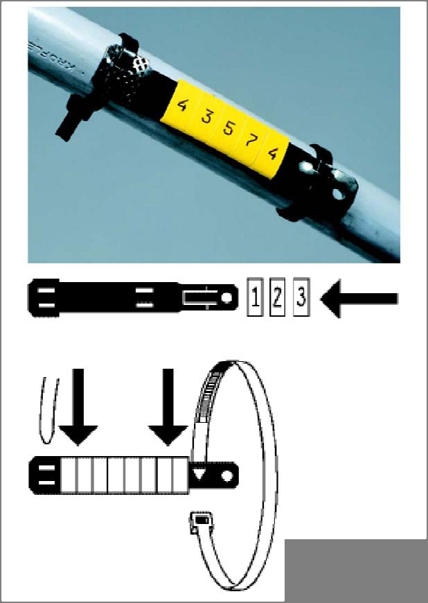
23 to the point of delivery shall remain with SaskPower, and the ownership of facilities beyond the point of delivery shall remain with the Customer. The point of delivery for oilfield Customers shall be within the road allowance when served by SaskPower s overhead system. The point of delivery shall be near the entrance to the oilfield lease site when served by SaskPower s underground system, unless there are technical or physical impediments. Where there are technical or physical impediments the location of the supply transformer and point of delivery will be by mutual agreement after load, voltage drop, splitter, and maintenance accessibility requirements have been considered. Each Customer conductor terminated in SaskPower equipment (F-Cabinet, splitter, or pad-mounted transformer) shall identify the facility owner and location of equipment served. Ownership may be indicated by abbreviation of the customer name or by the letters CO (Customer Owned) followed by a dash. Location information shall include (where applicable) Quadrant, LSD, Section, Township, and Range. Meridian may be omitted. Two digits shall be used for Section, Township, and Range to prevent confusion. Marking method shall be by affixing Partex type PK markers (or equivalent) with cable ties near the termination of each conductor. Generic drawings of the Partex markers are shown in Figure Note: As an example, for a Customer Owned cable feeding quadrant B of LSD 12 of W2M would have the label CO-B Buried Service Requirements Single Phase Oilfield Service Greater than 300 V For supply services up to 200 A, servicing options include: Customer supplied outside splitter with main disconnect as per Figure 2-10, Figure 2-14, and Table 2-1. SaskPower supplied F-Cabinet (240/480 V) as per Figure Polyphase Oilfield Service Greater Than 300 V For supply services up to 200 A, servicing options include: Customer supplied outside splitter with main disconnect as per Figure 2-10, Figure 2-14, and Table 2-1. SaskPower supplied F-Cabinet (limited to 200 A and a maximum of 600 V) as per Figure Secondary terminals of SaskPower supplied pad-mounted transformer as per Figure For 4160 V the only servicing option is the secondary terminals of SaskPower supplied pad-mounted transformer. For supply services greater than 200 A and up to 800A, servicing options include: Customer supplied outside splitter with meter socket as per Figure 2-10, Figure 2-11, and Table 2-1. Secondary terminals of SaskPower supplied pad-mounted transformer as per Figure For 4160 V the only servicing option is the secondary terminals of SaskPower supplied pad-mounted transformer. For supply services greater than 800A, servicing options include: Secondary terminals of SaskPower supplied pad-mounted transformer as per Figure
24 2.5 Metering General Requirements When the supply service is from a 4-wire wye system, the metering facilities shall be 4-wire wye requiring the system neutral to be brought into the instrument transformer compartment complete with connecting lug for connection to the voltage transformer. Meters and metering equipment shall have a minimum of 1 m of working space, clear of any obstruction, directly in front of the meter. When multiple meters are used, and are indoors, they shall be grouped together in a dedicated electrical room Meter Mounting Devices The meter socket will normally be supplied and installed by the Customer, with the following exceptions: Rural metering unit. F-cabinet. Metering is at the secondary terminals of SaskPower s 3-phase pad-mounted transformer. This applies to cases where: the transformer is dedicated to one Customer, and the Customer supplies the secondary conductors, and the supply voltage is less than 750 Volts. The use of current bypass switches is not permitted when self-contained meter sockets are used. For services that do not utilize a self-contained meter socket a current bypass switch shall be used and installed as per Figure All meter sockets shall: be supplied complete with screw type or snap action sealing rings. Slip-lock sealing rings and ringless meter sockets are not permitted. not be installed directly above, directly below, or within 1 m horizontally of a furnace, water heater, air exchanger, dryer, and/or similar exhaust vents (as per Code). When the point of delivery is the secondary terminals of SaskPower s pad-mounted transformer, the metering options are: Customer supplied meter socket(s) at their distribution center. SaskPower supplied meter socket at the 3-phase pad-mounted transformer, as per Figure Splitters shall have provision for installing a SaskPower seal. Where multiple meters are co-located, as in an electrical room, or a multi-gang meter socket, each meter enclosure shall be marked to indicate the address or unit number that it serves. This marking shall be on both the cover of the meter socket, and the interior of the meter socket enclosure to ensure that covers are not mixed up when they are removed. Marking shall be by way of a permanent engraved lamacoid or equivalent tag that is weather and ultraviolet resistant with 50mm (2 ) high letters affixed with permanent adhesive. 24
25 Whether the metering is at SaskPower's pad-mounted transformer or at the Customer's equipment, the Customer shall supply, install, and terminate the secondary conductors in consultation with SaskPower. Connection to or disconnection from SaskPower's system shall only be made by individuals authorized by SaskPower. Suitable cable support (as per Code) shall be supplied and installed by the Customer in a manner approved by SaskPower Self-Contained Meter Sockets Customer supplied 200 A meter sockets shall: Be configured and wired as per Figures 2-27 and Have line side connections suitable for aluminum conductors rated #6 to 4/0. Have minimum dimensions of 455 mm (vertical dimension) x 305 mm (horizontal dimension) x 125 mm (depth). Be located outdoors unless permission is granted by SaskPower Metering Services. A single meter socket, with dual wire connectors on the load side, shall be permitted two subdivisions, provided the total ampere rating of the two Customer disconnects do not exceed the ampere rating of the meter socket Transformer Rated Meter Sockets Meter sockets shall be: Be configured and wired as per Figure 2-27 and Figure Have a ground connection. Not exceed a circuit length of 11 metres from the instrument transformer enclosure. Exceptions require prior approval from SaskPower Metering Services. Located outdoors. Exceptions include: Meters grouped together in an electrical room. The meter is located in the same switchgear assembly as the instrument transformers and in a separate compartment. The meter compartment shall conform to the following dimensions: Depth mm (15") minimum to 450 mm (18")maximum Height mm (34") minimum Width mm (24") minimum The meter compartment shall be equipped with a hinged door, flush with the front of the switchgear, with provisions for sealing by SaskPower. A window is to be provided if the Customer wishes to read the meter. The meter compartment is to be located so that the meter can be mounted with its centre line at a height of 1500 mm to 1800 mm above floor level. The meter socket is separate from the switchgear, it may be wall-mounted adjacent to the switchgear, with approval from SaskPower Metering Services. Location poses a security or safety issue. In these cases the Customer shall apply to SaskPower Metering Services to determine an acceptable location Instrument Transformers and Enclosures When the main service exceeds 200 A or 600 V the instrument transformer enclosure shall be supplied and installed by the Customer except where padmount metering is utilized. For service voltage at 4160 V, the Customer shall supply and install the instrument transformer enclosure and meter socket. Revenue metering instrument transformers and other associated equipment supplied by SaskPower shall be used exclusively for the purpose of SaskPower revenue metering. 25
26 Services with multiple instrument transformer enclosures shall have a separate means of disconnect for each enclosure Instrument Transformers When the Customer supplies the instrument transformer enclosure, the instrument transformers shall be installed: and connected by the Customer as per Figure to permit the complete removal or installation. using all manufacturer s mounting holes. such that the name plates are clearly visible. Instrument transformers will not be shipped out of the province for installing in switchgear. Instrument transformer dimension diagrams will be forwarded upon request. Voltage transformers, 700 V class, shall be without fuses and be stationary mounted. Voltage transformers, 5 kv class, may be equipped with one fuse per transformer centrally mounted for 3-phase, 4-wire wye circuits as per Figure 2-30 and Figure Current transformers, 5 kv class, shall be as per Figure 2-30 and Figure The compartment may be required to be equipped with a draw out type, or swing out type, carriage with disconnect provisions for de-energizing and grounding the primary of each transformer upon withdrawal Instrument Transformer Enclosures When the Customer supplies the instrument transformer enclosure, it shall: be equipped with a hinged door with provision for padlocking and sealing by SaskPower. contain mounting plates or other acceptable means for securing the transformers. have an insulated splitter block provided for neutral conductors. be of the dimensions as per Table 2-2 (for services not utilizing bar type buss structure). For service entrance panels utilizing bar type buss structure and manufactured switchgear, provision shall be made for mounting current transformers and voltage transformers in a separate and completely barriered compartment. The compartment shall be large enough to contain three current transformers and three voltage transformers and to be readily accessible for maintenance and replacement of transformers with a means for padlocking and sealing by SaskPower. The instrument transformer enclosure shall be a minimum of 300 mm (12") above the floor from the bottom of enclosure, maximum 1800mm (6 ) to top of enclosure. In addition to the electrical clearances specified in the applicable CSA standard, a minimum physical separation of 50 mm must be maintained between instrument transformers and between the instrument transformer and the surrounding switchgear to provide adequate working clearances. Instrument transformer enclosures shall: be located either indoors or outdoors. be immediately adjacent to and on the load side of the individual Customer's main service disconnect. be readily accessible for testing or replacement of instrument transformers. contain only SaskPower instrument transformer(s) and associated Customer conductors. not be used as a splitter for other Customers. When switchgear is used, the Customer shall: 26
27 forward four (4) copies of preliminary revenue metering details and location drawings to the Manager, SaskPower Metering Services for approval. Switchgear design drawings should not be finalized before approval is received from the Manager, SaskPower Metering Services. Failure to do so may result in modifications required to the switchgear and delay of the service. notify the switchgear manufacturer of the revenue metering requirements after discussion with SaskPower Conduit and Secondary Wiring Requirements When the Customer supplies the instrument transformer enclosure, the Customer shall supply and install: a continuous run of conduit (minimum 35 mm (1¼ ) diameter) for the exclusive use of SaskPower between the instrument transformer enclosure and the meter enclosure (to a maximum circuit length of 11 metres). sealable LB fittings or similar conduit fittings, if required. the bond on the meter socket when PVC conduit is used. SaskPower shall supply and install: a continuous run of secondary conductors in the Customer supplied conduit between the instrument transformers and the meter test switch (such that there are no splices or interruptions). the test switch and the meter Metering Signals Any Customer requiring output signals from the SaskPower revenue meter is requested to contact the appropriate SaskPower Business Manager for applicability, availability, details, and costs. In the event that output signals are provided to the Customer, SaskPower will not accept any liabilities with respect to the use or loss of the output signals. 27
28 2.6 Installation Diagrams for Services up to and Including 5 kv 28
29
30
31
32
33
34
35
36
37
38
39
40
41
42
43
44
45
46
47
48
Customer Connection Guide Updates Effective May 2017
 This document provides a list of the updates to the EPCOR Distribution and Transmission Inc. (EDTI) Customer Connection Guide. If you have any questions, please contact EDTI Customer Engineering Services
SECTION 5 TRANSFORMERS
 SECTION 5 TRANSFORMERS Necessary transformers will be installed and maintained by The City of Aspen. The City of Aspen will not furnish transformers unless they are of standard size and voltage as established
Generation Interconnection Requirements at Voltages 34.5 kv and Below
 Generation Interconnection Requirements at Voltages 34.5 kv and Below 2005 March GENERATION INTERCONNECTION REQUIREMENTS AT 34.5 KV AND BELOW PAGE 1 OF 36 TABLE OF CONTENTS 1. INTRODUCTION 5 1.1. Intent
University of Central Florida Main Campus. Electric. Service and Meter Installations Requirements. Issued January 26 th, 2017.
 University of Central Florida Main Campus Electric Service and Meter Installations Requirements Issued January 26 th, 2017 1 P a g e Table of Contents 1. GENERAL INFORMATION... 3 2. DEFINITIONS... 3 3.
Page Electric Utility Service Specifications
 T Y P I C A L U N D E R G R O U N D S E R V I C E R E Q U I R E M E N T S 200 Amps Maximum - UG-1 Sheet 1 of 3 87 T Y P I C A L U N D E R G R O U N D S E R V I C E R E Q U I R E M E N T S 200 Amps Maximum
Customer Requirements RF Antenna Installations
 Application Terms Attachment requirements and clearances on the Pole for Radio Frequency (RF) antenna equipment installations. This standard is intended to allow electrical workers to perform their normal
Table of Contents. Introduction... 1
 Table of Contents Introduction... 1 1 Connection Impact Assessment Initial Review... 2 1.1 Facility Design Overview... 2 1.1.1 Single Line Diagram ( SLD )... 2 1.1.2 Point of Disconnection - Safety...
E N G I N E E R I N G M A N U A L
 1 1 1.0 PURPOSE The purpose of this document is to define policy and provide engineering guidelines for the AP operating companies (Monongahela Power Company, The Potomac Edison Company, and West Penn
DP&L s Technical Requirements for Interconnection and Parallel Operation of Distributed Generation
 DP&L s Technical Requirements for Interconnection and Parallel Operation of Distributed Generation Technical Requirements for Interconnection and Parallel Operation of Distributed Generation Single Phase
INTELLIMETER REGISTER
 INTELLIMETER REGISTER MODEL RG2 INSTALLATION AND CONNECTIONS INSTALLATION MANUAL WARNING: Any work on or near energized metering equipment can present a danger of electrical shock. All work on these products
CONSULTANT PROCEDURES & DESIGN GUIDELINES Liquid-Filled Utility Transformers UNIVERSITY OF MISSOURI
 GENERAL: The scope of this document is to provide instruction for the installation and testing of Medium Voltage, 3 Phase, Pad Mounted Transformers installed at the University of Missouri. Preferred transformers
OPERATING, METERING AND EQUIPMENT PROTECTION REQUIREMENTS FOR PARALLEL OPERATION OF LARGE-SIZE GENERATING FACILITIES GREATER THAN 25,000 KILOWATTS
 OPERATING, METERING AND EQUIPMENT PROTECTION REQUIREMENTS FOR PARALLEL OPERATION OF LARGE-SIZE GENERATING FACILITIES GREATER THAN 25,000 KILOWATTS AND MEDIUM-SIZE FACILITIES (5,000-25,000KW) CONNECTED
UNIVERSITY OF MISSOURI Liquid-Filled Utility Transformers 2016 Q1
 GENERAL: The scope of this document is to provide instruction for the installation and testing of Medium Voltage, 3 Phase, Pad Mounted Transformers installed at the University of Missouri. Preferred transformers
Article 225: Outside Branch Circuits And Feeders
 Part C: Code Book Questions Article 225: Outside Branch Circuits And Feeders 1.! Open (individual) aerial overhead conductors shall be insulated or covered when within! feet of a building.! (a) 10! (c)
3.1 Overview of ATCO Electric s URD System Design
 Page: 3-1 3.0 URD DESIGN GUIDELINES 3.1 Overview of ATCO Electric s URD System Design ATCO Electric s design for distribution power supply to URD areas is a primary looped supply system. This is generically
Chapter 1. Applied Grounding and Bonding. Applied Grounding and Bonding 9/18/2011. Introduction. Introduction. Paul Dobrowsky Member NEC Panel 5
 Applied Grounding and Bonding Paul Dobrowsky Member NEC Panel 5 1 Introduction This presentation is a representative sample from the following Chapters of Applied Grounding and Bonding. Chapter 1, Introduction
Broadband Step-Up Transformer. User Manual
 Broadband Step-Up Transformer User Manual 990-1930 09/2004 Introduction Introduction About this unit The APC Step-Up Transformer provides 220 V power from 60 VAC Broadband cable systems. Safety Electrical
Wisconsin Contractors Institute Continuing Education
 IMPORTANT NOTE: You should have received an email from us with a link and password to take your final exam online. Please check your email for this link. Be sure to check your spam folder as well. If you
MV ELECTRICAL TRANSMISSION DESIGN AND CONSTRUCTION STANDARD. PART 1: GENERAL 1.01 Transformer
 PART 1: GENERAL 1.01 Transformer A. This section includes liquid filled, pad mounted distribution transformers with primary voltage of 12kV or 4.16kV (The University will determine primary voltage), with
American Electrical Institute
 American Electrical Institute Oregon Electricians Continuing Education Grounding & Bonding (Article 250) 4 Hours American Electrical Institute PO Box 31131 Spokane, WA 99223 www.aeitraining.com Article
BED INTERCONNECTION TECHNICAL REQUIREMENTS
 BED INTERCONNECTION TECHNICAL REQUIREMENTS By Enis Šehović, P.E. 2/11/2016 Revised 5/19/2016 A. TABLE OF CONTENTS B. Interconnection Processes... 2 1. Vermont Public Service Board (PSB) Rule 5.500... 2
Article 250 Grounding & Bonding
 Article 250 Grounding & Bonding AMERICAN ELECTRICAL INSTITUTE N16 W23217 Stone Ridge Dr. Waukesha, WI 53188 855-780-5046 www.aeitraining.com DISCLAIMER NOTE: This course is APPROVED for continuing education
METER - INSTALLATION Pad Mount Transformer
 ER 1-210-C PAGE 1 OF 5 USE: Pad mount transformer secondary compartment LATEST REVISION: PREVIOUS REVISION 10-01-12 ORIGINATED 0-94 PREVIOUS NUMBER ER 700, 10-01-86 Added specification for placement and
MECKLENBURG COUNTY. Land Use and Environmental Service Agency Code Enforcement 9/8/10 ELECTRICAL CONSISTENCY MEETING. Code Consistency Questions
 conduit? 9/8/10 ELECTRICAL CONSISTENCY MEETING Code Consistency Questions 1. Can branch circuits of different services be installed in the same Yes, see 300.3(C)(1) for conductors of different systems
SPECIFICATIONS FOR NEW UNDERGROUND RESIDENTIAL DISTRIBUTION SYSTEMS
 Page: 4-1 4.0 URD Process and Documentation Requirements 4.1 Process Steps The process of developing underground distribution facilities in a residential area consists of 10 major steps, which are summarized
Wind Power Facility Technical Requirements CHANGE HISTORY
 CHANGE HISTORY DATE VERSION DETAIL CHANGED BY November 15, 2004 Page 2 of 24 TABLE OF CONTENTS LIST OF TABLES...5 LIST OF FIGURES...5 1.0 INTRODUCTION...6 1.1 Purpose of the Wind Power Facility Technical
UBC Technical Guidelines Section Edition Medium-Voltage Transformers Page 1 of 5
 Page 1 of 5 1.0 GENERAL 1.1 Coordination Requirements.1 UBC Energy & Water Services.2 UBC Building Operations 1.2 Description.1 UBC requirements for Substation Transformers. 2.0 MATERIAL AND DESIGN REQUIREMENTS
1. All electrical switches and outlets used shall be equal to Hubbell heavy duty, specification grade or equivalent quality.
 PART 1: GENERAL 1.01 Wiring Devices A. This section of the standard includes design requirements for wiring connections, including receptacles and switches to equipment specified in other sections. 1.02
INTERIM ARRANGEMENTS FOR GRID TIED DISTRIBUTED ENERGY RESOURCES. Technical Requirements for Grid-Tied DERs
 INTERIM ARRANGEMENTS FOR GRID TIED DISTRIBUTED ENERGY RESOURCES Technical Requirements for Grid-Tied DERs Projects Division 6/29/2017 Contents 1 Definitions and Acronyms... 1 2 Technical Interconnection
CONTINUING EDUC ATION
 3 CONTINUING EDUC ATION FOR WISCONSIN ELECTRICIANS 2017 NEC Article 250 2 Hours WISCONSIN CONTRACTORS INSTITUTE N16 W23217 Stone Ridge Drive Suite 290 Waukesha, WI 53188 262-409-4282 www.wcitraining.com
THE HILLCREST VILLAGE HOMEOWNERS ASSOCIATION, INC. RULES FOR INSTALLATION OF ANTENNAS
 THE HILLCREST VILLAGE HOMEOWNERS ASSOCIATION, INC. RULES FOR INSTALLATION OF ANTENNAS I. Preamble These rules are adopted by the Board of Directors of The Hillcrest Village Homeowners Association, Inc.,
2014 NEC Changes Part 1
 www.garyklinka.com Page 1 of 8 Instructions: Fee $20 1. Print these pages. 2. Circle the correct answers and transfer them to the answer sheet. 3. Page down to the last page for the verification forms
Electrical Wiring: Commercial, Seventh Canadian Edition
 Electrical Wiring Commercial Canadian 7th Edition Mullin SOLUTIONS MANUAL Full download at: https://testbankreal.com/download/electrical-wiring-commercialcanadian-7th-edition-mullin-solutions-manual/ Unit
OPERATING, METERING, AND EQUIPMENT PROTECTION REQUIREMENTS FOR PARALLEL OPERATION OF LARGE-SIZE GENERATING FACILITIES GREATER THAN 2,000 KILOWATTS
 OPERATING, METERING, AND EQUIPMENT PROTECTION REQUIREMENTS FOR PARALLEL OPERATION OF LARGE-SIZE GENERATING FACILITIES GREATER THAN 2,000 KILOWATTS CONNECTED TO THE DISTRIBUTION SYSTEM ORANGE AND ROCKLAND
SPECIFICATIONS FOR THE INSTALLATION OF CONDUIT SYSTEMS IN RESIDENTIAL SUBDIVISIONS. Notification of Completed Conduit Sections
 SPECIFICATIONS FOR THE INSTALLATION OF CONDUIT SYSTEMS IN RESIDENTIAL SUBDIVISIONS Section 1 Definitions 2 Scope of Work 3 Extent of Work 4 Inspection and Performance of Work 5 Trenching 6 Duct Installation
FAQ ON EARTHING STANDARDS 16/08/2018
 FAQ ON EARTHING STANDARDS 16/08/2018 This document has been updated to include changes made to substation earthing layouts that have been made necessary due to copper theft. The main changes to be aware
EI HIGH VOLTAGE INSULATION TESTING POLICY
 Network(s): Summary: ENGINEERING INSTRUCTION EI 09-0001 HIGH VOLTAGE INSULATION TESTING POLICY EPN, LPN, SPN This engineering instruction details the policy for the on-site insulation testing of new and
SDCS-03 DISTRIBUTION NETWORK GROUNDING CONSTRUCTION STANDARD (PART-II) OVERHEAD NETWORK GROUNDING. Rev. 01
 OVERHEAD NETWORK GROUNDING. Rev. 01") SEC DISTRIBUTION GROUNDING STANDARD SDCS-03 Part-II Rev.01 SDCS-03 DISTRIBUTION NETWORK GROUNDING CONSTRUCTION STANDARD (PART-II) OVERHEAD NETWORK GROUNDING Rev. 01 This specification is property of SEC
SEC DISTRIBUTION GROUNDING STANDARD SDCS-03 Part-II Rev.01 SDCS-03 DISTRIBUTION NETWORK GROUNDING CONSTRUCTION STANDARD (PART-II) OVERHEAD NETWORK GROUNDING Rev. 01 This specification is property of SEC
PROCEDURE FOR INSPECTION OF ELECTRICAL INSTALLATIONS ABOVE 250KVA
 PROCEDURE FOR INSPECTION OF ELECTRICAL INSTALLATIONS ABOVE 250KVA Generally inspection of electrical installations is carried out under Regulation-30 (Periodical inspection & testing) & Regulation-43 (Approval
Quality Control Checklist - Design Drawings
 Quality Control Checklist - Design Drawings Date Company Name Address Telephone Fax Email Job Number 1) Drawing Set a) Drawing one is site/location/incoming power i) Should contain location map if not
ECP HV INSULATION TESTING
 Document Number: ECP 11-0006 Network(s): Summary: All ENGINEERING COMMISSIONING PROCEDURE ECP 11-0006 HV INSULATION TESTING This standard details the policy for the on-site insulation testing of new and
1% Switchgear and Substations
 1% Switchgear and Substations Switchgear and substations are not always matters of concern for transmitter designers, -because they are often part of the facilities of a typical installation. However,
SDCS-03 DISTRIBUTION NETWORK GROUNDING CONSTRUCTION STANDARD (PART-I) UNDERGROUND NETWORK GROUNDING. Rev. 01
 UNDERGROUND NETWORK GROUNDING. Rev. 01") SDCS-03 DISTRIBUTION NETWORK GROUNDING CONSTRUCTION STANDARD (PART-I) UNDERGROUND NETWORK GROUNDING Rev. 01 This specification is property of SEC and subject to change or modification without any notice
SDCS-03 DISTRIBUTION NETWORK GROUNDING CONSTRUCTION STANDARD (PART-I) UNDERGROUND NETWORK GROUNDING Rev. 01 This specification is property of SEC and subject to change or modification without any notice
PREFACE ********************************************************** IT IS NOT INTENDED THAT THESE STANDARDS BE COPIED AND USED AS A SPECIFICATION!
 PREFACE This publication has been prepared as a guide for Architectural and Engineering (A&E) firms in the preparation of documents for the design and construction of new structures and the remodeling
SECTION PANELBOARDS
 PART 1 - GENERAL 1.1 DESCRIPTION SECTION 26 24 16 PANELBOARDS SPEC WRITER NOTE: Delete between // --- // if not applicable to project. Also, delete any other item or paragraph not applicable in the section
Electrical IP Red Seal Practice Exam
 Electrical IP Red Seal Practice Exam PRACTICE EXAM-3 1. What size 2 pole breaker must you use on a 3HP, 115V single phase motor? A. 40A B. 50A C. 80A. D. 100A. 2. An electrical equipment approved for use
6B.6 Substation Grounding
 1 No v 1 6 1 No v 1 6 Iu d a Mo r a r a n d ma n a g e r R a c h e le Ha n n o n Vo l.6 -S u b s ta tio n a n d Hig h Vo lta g e E q u ip me n t;p a r tb -S u b s ta tio n Co n fig u r a tio n s 1. Scope
SAFETY AND HEALTH STANDARD ELECTRICAL GROUNDING Effective Date: 07/17/10 Standard: Document Number: KUCSH0039 Rev: 4
 SAFETY AND HEALTH STANDARD ELECTRICAL GROUNDING Effective Date: 07/17/10 Standard: 16.10 Document Number: KUCSH0039 Rev: 4 16.10.1 INTRODUCTION 16.10.1.1 The intent of this standard is to ensure that continuity
Standard Prices for Generators 2010
 Standard Prices for Generators 2010 Distribution System Operator ESB Networks Page 1 of 13 CONTENTS 1.0 Background...3 2.0 Standard Pricing Approach...3 Schedule of Charges for generators excluding VAT...6
ENGINEERING STANDARD FOR INSTRUMENTS ELECTRICAL POWER SUPPLY AND DISTRIBUTION SYSTEMS FIRST EDITION MAY 2013
 ENGINEERING STANDARD FOR INSTRUMENTS ELECTRICAL POWER SUPPLY AND DISTRIBUTION SYSTEMS FIRST EDITION MAY 2013 This Standard is the property of Iranian Ministry of Petroleum. All rights are reserved to the
ISO Rules Part 500 Facilities Division 502 Technical Requirements Section Aggregated Generating Facilities Technical Requirements
 Division 502 Technical Applicability 1(1) Section 502.1 applies to: Expedited Filing Draft August 22, 2017 the legal owner of an aggregated generating facility directly connected to the transmission system
Click to edit Master title style. Click to edit Master title style. Northern Powergrid Asset Recording Guidance
 Click to edit Master title style Click to edit Master title style Northern Powergrid Asset Recording Guidance Rules for ICP & IDNO Version 1.0 April 2017 Introduction Accurate records for all assets are
SI-125 Power Amplifier Manual 6205 Kestrel Road; Mississauga, Ontario; Canada; L5T 2A1 November 2016, Rev 0.5
 SI-125 Power Amplifier Manual 6205 Kestrel Road; Mississauga, Ontario; Canada; L5T 2A1 November 2016, Rev 0.5 Phone: (905) 564-0801 Fax: (905) 564-0806 www.telecor.com E:\T2-108\T2-M108-ABC\T2-M108-B.doc/AD
Grounding Recommendations for On Site Power Systems
 Grounding Recommendations for On Site Power Systems Revised: February 23, 2017 2017 Cummins All Rights Reserved Course Objectives Participants will be able to: Explain grounding best practices and code
Contact Voltage Detection
 Contact Voltage Detection Midwest Rural Energy Conference 48th Annual Rural Energy Conference March 11-12 La Crosse, Wisconsin Chad Hadley, Senior Engineer Overview Contact Voltage Definition History Equipment
ELECTRIC GROUNDING AND WIRING REQUIREMENTS BOOTHS-METAL
 BELL SYSTEM PRACTICES Plant Series SECTION 508-100-100 Issue 3, October 1970 AT&TCo Standard ELECTRIC GROUNDING AND WIRING REQUIREMENTS BOOTHS-METAL I. GENERAL 1.01 This section is reissued to: Revise
EPG. by Chris C. Kleronomos
 April 1994 EFFECTIVE EQUIPMENT GROUNDING ECOS Electronics Corporation by Chris C. Kleronomos The quality of the electrical wiring and grounding in a facility containing sensitive electronic equipment is
Substation Preventive Maintenance
 Substation Preventive Maintenance PROVINCIAL ELECTRICITY AUTHORITY 1 Presentation Contents 1) A kind of substation 2) Electrical equipment details of AIS substation 3) Electrical equipment details of GIS
SECTION LOW-VOLTAGE ELECT. DIST. DESIGN AND CONSTRUCTION STANDARDS _ February 2015 PART I: GENERAL
 PART I: GENERAL 1.01 Wiring Devices A. This section of the standard includes design requirements for wiring connections, including receptacles and switches to equipment specified in other sections. a.
FACILITY RATINGS METHOD TABLE OF CONTENTS
 FACILITY RATINGS METHOD TABLE OF CONTENTS 1.0 PURPOSE... 2 2.0 SCOPE... 3 3.0 COMPLIANCE... 4 4.0 DEFINITIONS... 5 5.0 RESPONSIBILITIES... 7 6.0 PROCEDURE... 8 6.4 Generating Equipment Ratings... 9 6.5
Education & Training
 Distribution System Operator Certificate This program provides you with a proficient working knowledge in modern electric power distribution systems. These four classes are designed to walk students through
WESTERN UNDERGROUND COMMITTEE GUIDE 2.6 (2.6/00/0868)
") WESTERN UNDERGROUND COMMITTEE GUIDE 2.6 (2.6/00/0868) THREE-PHASE SUBSURFACE UNDERGROUND COMMERCIAL DISTRIBUTION (UCD) TRANSFORMER NOTE: This "Guide" summarizes the opinions, recommendations, and practices
WESTERN UNDERGROUND COMMITTEE GUIDE 2.6 (2.6/00/0868) THREE-PHASE SUBSURFACE UNDERGROUND COMMERCIAL DISTRIBUTION (UCD) TRANSFORMER NOTE: This "Guide" summarizes the opinions, recommendations, and practices
Protective Relaying for DER
 Protective Relaying for DER Rogerio Scharlach Schweitzer Engineering Laboratories, Inc. Basking Ridge, NJ Overview IEEE 1547 general requirements to be met at point of common coupling (PCC) Distributed
2/15/2015. Current will always try to return to its source. In order for there to be current, there must be a complete circuit
 Current will always try to return to its source In order for there to be current, there must be a complete circuit Current will take as many paths or circuits available to it to return to the source The
Distribution/Substation Transformer
 Distribution/Substation Transformer Type VFI, Vacuum Fault Interrupter Transformer Option Functional Specification Guide Functional specification for 15 kv, 25 kv, or 35 kv vacuum fault interrupter distribution/substation
The Importance of the Neutral-Grounding Resistor. Presented by: Jeff Glenney, P.Eng. and Don Selkirk, E.I.T.
 The Importance of the Neutral-Grounding Resistor Presented by: Jeff Glenney, P.Eng. and Don Selkirk, E.I.T. Presentation Preview What is high-resistance grounding (HRG)? What is the purpose of HRG? Why
SWITCHING SAFETY & RELIABILITY CONFERENCE
 SWITCHING SAFETY & RELIABILITY CONFERENCE JARGON WORKSHEET Energize (v) Energize is the process of applying rated voltage to circuit or equipment. Modified IEEE or OSHA from Adj. to verb. To make a piece
POWER DELEGATOR SERIES 7200A POWER DISTRIBUTION UNIT WITH POWER CONDITIONING GENERAL SPECIFICATIONS
 POWER DELEGATOR SERIES 7200A POWER DISTRIBUTION UNIT WITH POWER CONDITIONING GENERAL SPECIFICATIONS 1.0 SCOPE The following specification describes the features, design, and application of the Series 7200A
7. INSPECTION AND TEST PROCEDURES
 7.1 Switchgear and Switchboard Assemblies A. Visual and Mechanical Inspection 1. Compare equipment nameplate data with drawings and specifications. 2. Inspect physical and mechanical condition. 3. Inspect
a) Determine the smallest, standard-sized circuit breaker that should be used to protect this branch circuit.
 Determine the smallest, standard-sized circuit breaker that should be used to protect this branch circuit.") ECET4520 Exam II Sample Exam Problems Instructions: This exam is closed book, except for the reference booklet provided by your instructor and one (8.5 x11 ) sheet of handwritten notes that may not contain
ECET4520 Exam II Sample Exam Problems Instructions: This exam is closed book, except for the reference booklet provided by your instructor and one (8.5 x11 ) sheet of handwritten notes that may not contain
The NOVA Recloser shall be designed and tested in accordance with the following standards as applicable:
 Reclosers NOVA Three-Phase Recloser Functional Specification Guide Functional specification for NOVA three-phase recloser 1. Scope This specification describes the features and ratings of the NOVA recloser.
WAVEFORM CORRECTOR (WAVEFORM CORRECTORS) REPLACES SURGE PROTECTION DEVICES (SPD) PREVIOUSLY KNOWN AS (TVSS)
 REPLACES SURGE PROTECTION DEVICES (SPD) PREVIOUSLY KNOWN AS (TVSS)") WAVEFORM CORRECTOR (WAVEFORM CORRECTORS) REPLACES SURGE PROTECTION DEVICES (SPD) PREVIOUSLY KNOWN AS (TVSS) 1 PART 1: GENERAL This section describes materials and installation requirements for low voltage
WAVEFORM CORRECTOR (WAVEFORM CORRECTORS) REPLACES SURGE PROTECTION DEVICES (SPD) PREVIOUSLY KNOWN AS (TVSS) 1 PART 1: GENERAL This section describes materials and installation requirements for low voltage
TABLE OF CONTENTS. References
 ANALYTICAL X-RAY EQUIPMENT USE POLICIES & PROCEDURES Page 1 of 9 Revised: 11/24/2003 TABLE OF CONTENTS 1.0 General 2.0 Purpose 3.0 Scope and Authority 4.0 Equipment Requirements 4.0.1 Safety device 4.0.2
The Variable Threshold Neutral Isolator (VTNI)
") The Variable Threshold Isolator (VTNI) Installation Instructions INTRODUCTION The is designed specifically for installation between the primary neutral of a power utility distribution system and the secondary
The Variable Threshold Isolator (VTNI) Installation Instructions INTRODUCTION The is designed specifically for installation between the primary neutral of a power utility distribution system and the secondary
ACCESS TO HIGH VOLTAGE APPARATUS
 CORPORATE PROCEDURE ACCESS TO HIGH VOLTAGE APPARATUS Approved By: Prepared By: Issue Date: 17/6/2011 Andrew Macrides Access to Apparatus Rules File No: Managing Director Committee QDOC2011/63 Status: Approved
NEC 2014 Code Changes
 NEC 2014 Code Changes Articles 200-215.3 CHANGES FROM 2011 CODE ARE IN RED Chapter 2 - Wiring and Protection ARTICLE 200 Use and Identification of Grounded Conductors 200.2 General Grounded Conductors
ECP HV INSULATION TESTING
 Document Number: ECP 11-0006 Network(s): Summary: ENGINEERING COMMISSIONING PROCEDURE EPN, LPN, SPN ECP 11-0006 HV INSULATION TESTING This standard details the policy for the on-site insulation testing
AN EXAMPLE OF A STANDARD ARC FLASH PPE LABELING STRATEGY
 The Electrical Power Engineers Qual-Tech Engineers, Inc. 201 Johnson Road Building #1 Suite 203 Houston, PA 15342-1300 Phone 724-873-9275 Fax 724-873-8910 www.qualtecheng.com AN EXAMPLE OF A STANDARD ARC
TABLE OF CONTENT
 Page : 1 of 34 Project Engineering Standard www.klmtechgroup.com KLM Technology #03-12 Block Aronia, Jalan Sri Perkasa 2 Taman Tampoi Utama 81200 Johor Bahru Malaysia TABLE OF CONTENT SCOPE 3 REFERENCES
Generation and Load Interconnection Standard
 Generation and Load Interconnection Standard Rev. 0A DRAFT Name Signature Date Prepared: Approved: VP Acceptance APEGGA Permit to Practice P-08200 TABLE OF CONTENTS 1.0 INTRODUCTION...5 1.1 Purpose...5
NORTH HARRIS COUNTY REGIONAL WATER AUTHORITY. Section ELECTRICAL IDENTIFICATION
 PART 1 GENERAL 1.01 SUMMARY Section 16195 A. This Section includes electrical identification for the following: 1. Nameplates and labels 2. Wire and cable markers 3. Conduit markers 4. Cable tray markers
Protection of Electrical Networks. Christophe Prévé
 Protection of Electrical Networks Christophe Prévé This Page Intentionally Left Blank Protection of Electrical Networks This Page Intentionally Left Blank Protection of Electrical Networks Christophe Prévé
Generation and Load Interconnection Standard
 Generation and Load Interconnection Standard Rev. 0 DRAFT Name Signature Date Prepared: Approved: VP Acceptance APEGGA Permit to Practice P-08200 TABLE OF CONTENTS 1.0 INTRODUCTION...5 1.1 Purpose...5
EDS LV SUPPLIES TO MOBILE PHONE BASE STATIONS MOUNTED ON TRANSMISSION TOWERS
 ENGINEERING DESIGN STANDARD EDS 08-2109 LV SUPPLIES TO MOBILE PHONE BASE STATIONS MOUNTED ON TRANSMISSION TOWERS Network(s): Summary: EPN, LPN, SPN This standard provides guidance on the installation of
SHARED TENANT SERVICE (STS) ARRANGEMENTS
 ARRANGEMENTS") Southwestern Bell Telephone 2nd Revised Sheet 1 Company d/b/a AT&T Missouri Replacing 1st Revised Sheet 1 37.1 Definition of Service 37.1.1 Shared Tenant Service (STS) Arrangements are the provision of
Southwestern Bell Telephone 2nd Revised Sheet 1 Company d/b/a AT&T Missouri Replacing 1st Revised Sheet 1 37.1 Definition of Service 37.1.1 Shared Tenant Service (STS) Arrangements are the provision of
ISO Rules Part 500 Facilities Division 502 Technical Requirements Section Wind Aggregated Generating Facilities Technical Requirements
 Applicability 1(1) Section 502.1 applies to the ISO, and subject to the provisions of subsections 1(2), (3) and (4) to any: (a) a new wind aggregated generating facility to be connected to the transmission
S. C. Electric Cooperative s Specification for a Single-Phase, Single Bushing Overhead Distribution Transformer (Revised 10/2013)
") S. C. Electric Cooperative s Specification for a Single-Phase, Single Bushing Overhead Distribution Transformer (Revised 10/2013) 1.0 GENERAL 1.1 This specification covers the electrical and mechanical
S. C. Electric Cooperative s Specification for a Single-Phase, Single Bushing Overhead Distribution Transformer (Revised 10/2013) 1.0 GENERAL 1.1 This specification covers the electrical and mechanical
Company Directive STANDARD TECHNIQUE: TP14C. Distribution Business Provided Metering Facilities
 Company Directive STANDARD TECHNIQUE: TP14C Distribution Business Provided Metering Facilities Summary This standard technique document details the metering facilities to be provided by the distribution
Upgrading Your Electrical Distribution System To Resistance Grounding
 Upgrading Your Electrical Distribution System To Resistance Grounding The term grounding is commonly used in the electrical industry to mean both equipment grounding and system grounding. Equipment grounding
GUIDE FOR GENERATOR INTERCONNECTION THE WIRES OWNER DISTRIBUTION SYSTEM
 DATE: 200/06/2 PAGE 1 of GUIDE FOR GENERATOR INTERCONNECTION TO THE WIRES OWNER DISTRIBUTION SYSTEM The intent of this Guide is to establish the interconnection requirements of Distributed Resources with
Phase-phase/phase-neutral: 24/13.8 kv star, 13.8 kv delta, 12/6.9 kv star.
 Summary Of Interconnection Technical Guidelines for Renewable Energy Systems 0-100 kw under Standard Offer Contract (Extract from JPS Guide to Interconnection of Distributed Generation) This document is
Capstone Turbine Corporation Nordhoff Street Chatsworth CA USA Phone: (818) Fax: (818) Web:
 Fax: (818) Web:") Phone: (818) 734-5300 Fax: (818) 734-5320 Web: www.capstoneturbine.com Technical Reference Capstone MicroTurbine Electrical Installation 410009 Rev F (October 2013) Page 1 of 31 Capstone Turbine Corporation
Phone: (818) 734-5300 Fax: (818) 734-5320 Web: www.capstoneturbine.com Technical Reference Capstone MicroTurbine Electrical Installation 410009 Rev F (October 2013) Page 1 of 31 Capstone Turbine Corporation
SECTION COMMUNICATIONS ELECTRICAL POWER DISTRIBUTION
 SECTION 16715 COMMUNICATIONS ELECTRICAL POWER DISTRIBUTION PART 1 - GENERAL 1.01 SECTION DESCRIPTION AND BASIC REQUIREMENTS A. The Electrical Power Distribution System provides power distribution from
Customer Requirements Commercial Secondary Service
 Application Installation requirements for commercial services from Tacoma Power overhead or underground facilities. It applies to new construction or upgrades of older services. Electrical service may
DL102 Counter Loop Amplifier
 DL102 Counter Loop Amplifier USER MANUAL MAN 234A Contents Overview...3 System Includes...3 Maintenance and Recycling Instructions...3 Safety Information...4 Quick Setup...5 Setup...6 Loop Amplifier...6
MECKLENBURG COUNTY. Land Use and Environmental Service Agency Code Enforcement 2/9/11 ELECTRICAL CONSISTENCY MEETING. Code Consistency Questions
 MECKLENBURG COUNTY Land Use and Environmental Service Agency Code Enforcement 2/9/11 ELECTRICAL CONSISTENCY MEETING Code Consistency Questions 1. I have a 500 KVA generator, with no overcurrent protection
DUKE ENERGY CAROLINAS TRANSMISSION SYSTEM PLANNING GUIDELINES. Transmission Planning
 DUKE ENERGY CAROLINAS TRANSMISSION SYSTEM PLANNING GUIDELINES Transmission Planning TABLE OF CONTENTS I. SCOPE 1 II. TRANSMISSION PLANNING OBJECTIVES 2 III. PLANNING ASSUMPTIONS 3 A. Load Levels 3 B. Generation
UNIFIED FACILITIES GUIDE SPECIFICATIONS
 USACE / NAVFAC / AFCEC / NASA UFGS-26 00 00.00 20 (July 2006) ------------------------------- Preparing Activity: NAVFAC Superseding UFGS-26 00 00.00 20 (April 2006) UNIFIED FACILITIES GUIDE SPECIFICATIONS
FINAL - IT 30 ELECTRICAL INSPECTOR EXAMINATION ANSWER SCHEDULE. Question 1 Marks Reference Marking notes. (2 marks) EA 2
 EA 2") FINAL - IT 30 ELECTRICAL INSPECTOR EXAMINATION ANSWER SCHEDULE Notes:1. (1 mark) means that the preceding statement/answer earns 1 mark. 2. This schedule sets out the expected answers to the examination
FINAL - IT 30 ELECTRICAL INSPECTOR EXAMINATION ANSWER SCHEDULE Notes:1. (1 mark) means that the preceding statement/answer earns 1 mark. 2. This schedule sets out the expected answers to the examination
VARIABLE FREQUENCY DRIVE SPECIFICATION
 VARIABLE FREQUENCY DRIVE SPECIFICATION 1.0. SUMMARY The use of variable frequency drives (VFDs) in conjunction with wastewater lift stations has been identified as a means improve efficiency and to moderate