Chapter 6 Bandwidth Utilization: Multiplexing and Spreading 6.1
|
|
|
- Sherman Lester
- 5 years ago
- Views:
Transcription


1 Chapter 6 Bandwidth Utilization: Multiplexing and Spreading 6.1 Copyright The McGraw-Hill Companies, Inc. Permission required for reproduction or display.
2 Note Bandwidth utilization is the wise use of available bandwidth to achieve specific goals. Efficiency can be achieved by Multiplexing (BW sharing); privacy and anti-jamming can be achieved by Spreading (BW sharing & protection). 6.2
3 MULTIPLEXING Whenever the bandwidth of a medium linking two devices is greater than the bandwidth needs of the devices, the link can be shared. Multiplexing is the set of techniques that allows the simultaneous transmission of multiple signals across a single data link. As data and telecommunications use increases, so does traffic. Topics discussed in this section: Frequency-Division Multiplexing (FDM) Wavelength-Division Multiplexing (WDM) Synchronous Time-Division Multiplexing (Synchronous TDM) Statistical Time-Division Multiplexing (Statistical TDM)
 combines lines on the left into a single stream (many-to-one) Demultiplexer (DEMUX) separates the stream back into its component")
4 Figure 6.1 Dividing a link into channels refers to physical path refers to portion of link that carries transmission 6.4 n input lines share bandwidth of one link Multiplexer (MUX) combines lines on the left into a single stream (many-to-one) Demultiplexer (DEMUX) separates the stream back into its component transmission (one-to-many) and directs them to their corresponding lines

5 6.5 Figure 6.2 Categories of multiplexing

6 ใน Channel ท ม Bandwidth จำก ด เรำจะแบ งใช งำนจำก multiple device ได อย ำงไร f1 f2 f3 f4 t T1 T2 T3 T4 t d1c1 + d2c2 + d3c3 + d4c t
 Analog signal Shared Analog Transmission (sub-channels) Analog signal FDM can be applied when bandwidth of link (in hertz) is greater than the combined")
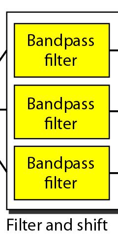
7 Figure 6.3 Frequency-division multiplexing (FDM) Analog signal Shared Analog Transmission (sub-channels) Analog signal FDM can be applied when bandwidth of link (in hertz) is greater than the combined bandwidths of signals to be transmitted Signals generated by each sending device modulate different carrier frequencies and then combined into a single composite signal that can be transported by the link Channels can be separated by strips of unused bandwidth, called guard channel, to prevent signals from overlapping 6.7

8 Note FDM is an analog multiplexing technique that combines analog signals. 6.8

9 Figure 6.4 FDM process 6.9 Multiplexing

10 Figure 6.5 FDM demultiplexing example 6.10 Demultiplexing
11 Example 6.1 Assume that a voice channel occupies a bandwidth of 4 khz. We need to combine three voice channels into a link with a bandwidth of 12 khz, from 20 to 32 khz. Show the configuration, using the frequency domain. Assume there are no guard bands. Solution We shift (modulate) each of the three voice channels to a different bandwidth, as shown in Figure 6.6. We use the 20- to 24-kHz bandwidth for the first channel, the 24- to 28-kHz bandwidth for the second channel, and the 28- to 32-kHz bandwidth for the third one. Then we combine them as shown in Figure


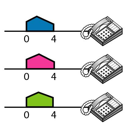
12 Figure 6.6 Example 6.1 fc1 = 22 FDM fc2 = 26 fc3 = 30 Demodulator Demodulator Demodulator 6.12
13 Example 6.2 Five channels, each with a 100-KHz bandwidth, are to be multiplexed together. What is the minimum bandwidth of the link if there is a need for a guard band of 10 KHz between the channels to prevent interference? Solution For five channels, we need at least four guard bands. This means that the required bandwidth is at least (5 x 100) + (4 x 10) = 540 KHz, as shown in Figure

14 6.14 Figure 6.7 Example 6.2
15 Example 6.3 Four data channels (digital), each transmitting at 1 Mbps, use a satellite channel of 1 MHz. Design an appropriate configuration using FDM Solution The satellite channel is analog. We divide it into four channels, each channel having a 250-KHz bandwidth. Each digital channel of 1 Mbps is modulated such that each 4 bits are modulated to 1 Hz. One solution is 16-QAM modulation. Figure 6.8 shows one possible configuration. 6.15


16 Figure 6.8 Example 6.3 Digital Data Analog Signal Analog signal 6.16

17 6.17 Figure 6.9 Analog hierarchy
18 Example 6.4 The Advanced Mobile Phone System (AMPS) uses two bands. The first band, 824 to 849 MHz, is used for sending; and 869 to 894 MHz is used for receiving. Each user has a bandwidth of 30 KHz in each direction. The 3-KHz voice is modulated using FM, creating 30 KHz of modulated signal. How many people can use their cellular phones simultaneously? Solution Each band is 25 MHz. If we divide 25 MHz into 30 KHz, we get In reality, the band is divided into 832 channels. Of these, 42 channels are used for control, which means only 790 channels are available for cellular phone users. 6.18
 =c / f1 =c / f2 =c / f3 ช วง wavelength ท ใช งำน 1550 nm Channel space: λ= c / f λ=wavelength c = Light Speed SDH/SONET -> 50 GHz/ channel, 32 channels -> 2.")
19 Figure 6.10 Wavelength-division multiplexing (WDM) =c / f1 =c / f2 =c / f3 ช วง wavelength ท ใช งำน 1550 nm Channel space: λ= c / f λ=wavelength c = Light Speed SDH/SONET -> 50 GHz/ channel, 32 channels -> 2.5 Gbps x 32 = 80 Gbps (1999)Bell LAB: 10 GHz/ channel, 1022 channels -> 2.5 Gbps x 1022 = Tbps (2002) NEC: 10 GHz/ channel, 273 channels -> 40 Gbps x 273 = 10.9 Tbps (2011) NEC: 10 GHz/ channel, 370 channels -> 274 Gbps x 370 = Tbps
20 Note WDM is an analog multiplexing technique to combine optical signals. 6.20

21 Figure 6.11 Prisms in wavelength-division multiplexing and demultiplexing Ex. Synchronous Optical Network (SONET) 6.21


22 Figure 6.12 Time Division Multiplexing (TDM) 6.22 TDM is digital multiplexing technique for combining several low-rate channels into one high bandwidth of link by Sharing Time TDM allows digital data from different sources are combined into one Timeshared Link Analog data can be sampled, change to digital data, and then multiplexed by using TDM
23 Note TDM is a digital multiplexing technique for combining several low-rate channels into one high-rate one. TDM can be divided into two different scheme 1. Synchronous TDM 2. Statistical TDM 6.23


24 Figure 6.13 Synchronous Time-Division Multiplexing unit 6.24
25 Example 5 Four 1-Kbps connections are multiplexed together. A unit is 1 bit. Find (1) the duration of 1 bit before multiplexing, (2) the transmission rate of the link, (3) the duration of a time slot, and (4) the duration of a frame? Solution We can answer the questions as follows: 1. The duration of 1 bit is 1/1 Kbps, or s (1 ms). 2. The rate of the link is 4 Kbps. 3. The duration of each time slot = 1/rate of Link = 1/4 ms or 250 ms. 4. The duration of a frame = 1/ frame rate = 1 ms.
26 Example 6.5 In Figure 6.13, the data rate for each input connection is 1 kbps. If 1 bit at a time is multiplexed (a unit is 1 bit, 3 input), what is the duration of (a) each input slot, (b) each output slot, and (c) each frame? Solution We can answer the questions as follows: a. The data rate of each input connection is 1 kbps. This means that the bit duration is 1/1000 s or 1 ms. The duration of the input time slot is 1 ms (same as bit duration). 6.26
27 Example 6.5 (continued) b. The duration of each output time slot is one-third of the input time slot. This means that the duration of the output time slot is 1/3 ms. c. Each frame carries three output time slots. So the duration of a frame is 3 1/3 ms, or 1 ms. Duration of a frame is same as duration of input unit 6.27
28 Example 6.6 Figure 6.14 shows synchronous TDM with a data stream for each input and one data stream for the output. The unit of data is 1 bit. Find (a) the input bit duration, (b) the output bit duration, (c) the output bit rate, and (d) the output frame rate. Solution We can answer the questions as follows: a. The input bit duration is the inverse of the bit rate: 1/1 Mbps = 1 μs. b. The output bit duration is one-fourth of the input bit duration, or ¼ μs or 0.25 μs 6.28
29 Example 6.6 (continued) c. The output bit rate is the inverse of the output bit duration or 1/(4μs) or 4 Mbps. This can also be deduced from the fact that the output rate is 4 times as fast as any input rate; so the output rate = 4 1 Mbps = 4 Mbps. d. The frame rate is always the same as any input rate. So the frame rate is 1,000,000 frames per second (1 M frames per second). Because we are sending 4 bits in each frame, we can verify the result of the previous question by multiplying the frame rate by the number of bits per frame. 6.29
30 6.30 Figure 6.14 Example 6.6

31 6.31 Figure 6.15 Interleaving
32 Example 6.8 Four channels are multiplexed using TDM. If each channel sends 100 bytes /s and we multiplex 1 byte per channel, show the frame traveling on the link, the size of the frame, the duration of a frame, the frame rate, and the bit rate for the link. Solution The multiplexer is shown in Figure ) Each frame carries 1 byte from each channel; the size of each frame, therefore, is 4 bytes, or 32 bits. 2)) Duration of frame = 1/100 = 0.01 s 3) Because each channel is sending 100 bytes/s and a frame carries 1 byte from each channel, the frame rate must be 100 frames per second. 4) The bit rate is , or 3200 bps. 6.32

33 6.33 Figure 6.16 Example 6.8
34 Example 6.9 A multiplexer combines four 100-kbps channels using a time slot of 2 bits. Show the output with four arbitrary inputs. What is the frame rate? What is the frame duration? What is the bit rate? What is the bit duration? Solution Figure 6.17 shows the output for four arbitrary inputs. The link carries 50,000 frames per second. (Frame rate = 100 kbps / 2 bits) 1) The frame duration is therefore 1/50,000 s or 20 μs. 2) The frame rate is 50,000 frames per second, and 3) each frame carries 8 bits; the bit rate is 50,000 8 = 400,000 bits or 400 kbps. 4) The bit duration is 1/400,000 s, or 2.5 μs. 6.34


35 Figure 6.17 Example 6.9 Interleaving Unit = 2 bits TDM: 2bits/slot Frame rate = 100 kbps / 2 bits = 50 kframes / s 6.35

36 6.36 Figure 6.18 Empty slots in Synchronous TDM
37 Figure 6.19 Multilevel multiplexing Two input lines can be multiplexed together 6.37
38 Figure 6.20 Multiple-slot multiplexing Serial to Parallel Converter 6.38
39 6.39 Figure 6.21 Pulse stuffing

40 Figure 6.22 Framing bits Synchronization bit or framing bit 6.40
41 Example 6.10 We have four sources, each creating 250 characters per second. If the interleaved unit is a character and 1 synchronizing bit is added to each frame, find (a) the data rate of each source, (b) the duration of each character in each source, (c) the frame rate, (d) the duration of each frame, (e) the number of bits in each frame, and (f) the data rate of the link. Solution We can answer the questions as follows: a. The data rate of each source is = 2000 bps = 2 kbps. 6.41
42 Example 6.10 (continued) 6.42 b. Each source sends 250 characters per second; therefore, the duration of a character is 1/250 s, or 4 ms. c. Each frame has one character from each source, which means the link needs to send 250 frames per second to keep the transmission rate of each source. d. The duration of each frame is 1/250 s, or 4 ms. Note that the duration of each frame is the same as the duration of each character coming from each source. e. Each frame carries 4 characters and 1 extra synchronizing bit. This means that each frame is = 33 bits. เพ มเต ม f. Data rate of Link = 250 frame/sec. x 33 bits = 8,250 bps ข อ f. 250 frame/sec. x 32 bits = 8,000 bps (No. Sync. Bit)
43 Example 6.11 Two channels, one with a bit rate of 100 kbps and another with a bit rate of 200 kbps, are to be multiplexed. How this can be achieved? What is the frame rate? What is the frame duration? What is the bit rate of the link? Solution We can allocate one slot to the first channel and two slots to the second channel. (using Serial to Parallel convertor) Each frame carries 3 bits. -The frame rate is 100,000 frames per second because it carries 1 bit from the first channel. - Frame duration = 1/100,000 sec. or 10 μs - The bit rate is 100,000 frames/s 3 bits per frame, or 300 kbps. 6.43


 x")

44 Figure 6.23 Digital hierarchy (Digital signal service: DS) 4 x (24 x 64) kbps plus 168 kbps of overhead (24x4x7) x 64kbps plus Mbps of overhead 4 (24x4x7x6) x 64kbps plus Mbps of overhead x 64kbps plus 8 kbps of overhead 24x64 kbps = 1536 kbps = Mbps 6.44

45 6.45 Table 6.1 DS and T line rates


46 Figure 6.24 T-1 line for multiplexing telephone lines Analog Digital Digital 6.46
47 6.47 Figure 6.25 T-1 frame structure

48 6.48 Table 6.2 E line rates
49 6.49 Figure 6.26 TDM slot comparison

50 Inverse Multiplexing McGraw-Hill The McGraw-Hill Companies, Inc., 2000
51 6-1 SPREAD SPECTRUM (SS) ใช ใน wireless communication ว ตถ ประสงค ใช Bandwidth ของส อให ค มค าท ส ด โดยรวมส ญญาณจากหลายๆ user ส งไปด วยก น ป องก นการรบกวนจากผ ไม หว งด prevent eavesdropping and jamming
 bandwidth ของแต ละ user ให เป น Spread spectrum")
52 6-1 SPREAD SPECTRUM 6.52 หล กการ -combine signals from different sources to fit into a larger bandwidth - ขยาย (spread) bandwidth ของแต ละ user ให เป น Spread spectrum bandwidth (Bss) add redundancy. Techniques: Frequency Hopping Spread Spectrum (FHSS) Direct Sequence Spread Spectrum (DSSS)
53 Figure 6.28 Frequency hopping spread spectrum (FHSS) PN 6.53
54 6.54 Figure 6.29 Frequency selection in FHSS
55 6.55 Figure 6.30 FHSS cycles

56 6.56 Figure 6.31 Bandwidth sharing
57 Figure 6.32 Direct Sequence Spread Spectrum (DSSS) -Spreading Code -Chipping sequence 6.57
58 6.58

59 6.59 Figure 6.33 DSSS example
Bandwidth utilization is the wise use of available bandwidth to achieve specific goals.
 Note Bandwidth Utilization: Multiplexing and Spreading Bandwidth utilization is the wise use of available bandwidth to achieve specific goals. Efficiency can be achieved by multiplexing; i.e., sharing
Chapter 6 Bandwidth Utilization: Multiplexing and Spreading 6.1
 Chapter 6 Bandwidth Utilization: Multiplexing and Spreading 6.1 Copyright The McGraw-Hill Companies, Inc. Permission required for reproduction or display. 3-6 PERFORMANCE One important issue in networking
Bandwidth Utilization:
 CHAPTER 6 Bandwidth Utilization: In real life, we have links with limited bandwidths. The wise use of these bandwidths has been, and will be, one of the main challenges of electronic communications. However,
Bandwidth Utilization:
 CHAPTER 6 Bandwidth Utilization: Solutions to Review Questions and Exercises Review Questions 1. Multiplexing is the set of techniques that allows the simultaneous transmission of multiple signals across
Bandwidth Utilization: Multiplexing and Spreading
 CHAPTER 6 Bandwidth Utilization: Multiplexing and Spreading In real life, we have links with limited bandwidths. The wise use of these bandwidths has been, and will be, one of the main challenges of electronic
*Most details of this presentation obtain from Behrouz A. Forouzan. Data Communications and Networking, 5 th edition textbook
 *Most details of this presentation obtain from Behrouz A. Forouzan. Data Communications and Networking, 5 th edition textbook 1 Multiplexing Frequency-Division Multiplexing Time-Division Multiplexing Wavelength-Division
MODULE IV. End Sem. Exam Marks. Syllabus
 MODULE IV Syllabus Multiplexing- Space Division Multiplexing, Frequency Division Multiplexing, Wave length Division Multiplexing - Time Division multiplexing: Characteristics, Digital Carrier system, SONET/SDH,
Multiplexing. Chapter 8. Frequency Division Multiplexing Diagram. Frequency Division Multiplexing. Multiplexing
 Multiplexing Chapter 8 Multiplexing Frequency Division Multiplexing FDM Useful bandwidth of medium exceeds required bandwidth of channel Each signal is modulated to a different carrier frequency Carrier
CS420/520 Axel Krings Page 1 Sequence 8
 Chapter 8: Multiplexing CS420/520 Axel Krings Page 1 Multiplexing What is multiplexing? Frequency-Division Multiplexing Time-Division Multiplexing (Synchronous) Statistical Time-Division Multiplexing,
P. 241 Figure 8.1 Multiplexing
 CH 08 : MULTIPLEXING Multiplexing Multiplexing is multiple links on 1 physical line To make efficient use of high-speed telecommunications lines, some form of multiplexing is used It allows several transmission
(Refer Slide Time: 2:23)
") Data Communications Prof. A. Pal Department of Computer Science & Engineering Indian Institute of Technology, Kharagpur Lecture-11B Multiplexing (Contd.) Hello and welcome to today s lecture on multiplexing
Data Communications Prof. A. Pal Department of Computer Science & Engineering Indian Institute of Technology, Kharagpur Lecture-11B Multiplexing (Contd.) Hello and welcome to today s lecture on multiplexing
Computer Networks: Multiplexing
 Computer Networks: Multiplexing EE1001 Prof. Taek M. Kwon Department of Electrical Engineering, UMD Outline EE 4321 Multiplexing EE 4321: Computer Networks EE Technical Elective Course, 3 credits Network
EEE 309 Communication Theory
 EEE 309 Communication Theory Semester: January 2016 Dr. Md. Farhad Hossain Associate Professor Department of EEE, BUET Email: mfarhadhossain@eee.buet.ac.bd Office: ECE 331, ECE Building Part 08 Multiplexing
Physical Layer. Dr. Sanjay P. Ahuja, Ph.D. Fidelity National Financial Distinguished Professor of CIS. School of Computing, UNF
 Physical Layer Dr. Sanjay P. Ahuja, Ph.D. Fidelity National Financial Distinguished Professor of CIS School of Computing, UNF Multiplexing Transmission channels are expensive. It is often that two communicating
Multiplexing. Dr. Manas Khatua Assistant Professor Dept. of CSE IIT Jodhpur
 CS311: DATA COMMUNICATION Multiplexing Dr. Manas Khatua Assistant Professor Dept. of CSE IIT Jodhpur e-mail: manaskhatua@iitj.ac.in Outline of the Lecture What is Multiplexing and why is it used? Basic
UNIT 6 ANALOG COMMUNICATION & MULTIPLEXING YOGESH TIWARI EC DEPT,CHARUSAT
 UNIT 6 ANALOG COMMUNICATION & MULTIPLEXING YOGESH TIWARI EC DEPT,CHARUSAT Syllabus Multiplexing, Frequency-Division Multiplexing Time-Division Multiplexing Space-Division Multiplexing Combined Modulation
INTRODUCTION TO COMMUNICATION SYSTEMS AND TRANSMISSION MEDIA
 COMM.ENG INTRODUCTION TO COMMUNICATION SYSTEMS AND TRANSMISSION MEDIA 9/9/2017 LECTURES 1 Objectives To give a background on Communication system components and channels (media) A distinction between analogue
CSCD 433 Network Programming Fall Lecture 5 Physical Layer Continued
 CSCD 433 Network Programming Fall 2016 Lecture 5 Physical Layer Continued 1 Topics Definitions Analog Transmission of Digital Data Digital Transmission of Analog Data Multiplexing 2 Different Types of
Outline of the Lecture
 CS311: DATA COMMUNICATION Multiplexing by Dr. Manas Khatua Assistant Professor Dept. of CSE IIT Jodhpur E-mail: manaskhatua@iitj.ac.in Web: http://home.iitj.ac.in/~manaskhatua http://manaskhatua.github.io/
Question Paper Profile
 Question Paper Profile Max. Marks : 70 Time: 3 Hrs. Q.1) A) Attempt any FIVE of the following. 10 Marks a) Define the term Standard. State its two categories. b) List any two advantages of Unguided Media.
William Stallings Data and Computer Communications. Chapter 8 Multiplexing. Multiplexing
 William Stallings Data and Computer Communications Chapter 8 Multiplexing Multiplexing 1 Frequency Division Multiplexing FDM Useful bandwidth of medium exceeds required bandwidth of channel Each signal
King Fahd University of Petroleum & Minerals Computer Engineering Dept
 King Fahd University of Petroleum & Minerals Computer Engineering Dept COE 342 Data and Computer Communications Term 021 Dr. Ashraf S. Hasan Mahmoud Rm 22-144 Ext. 1724 Email: ashraf@ccse.kfupm.edu.sa
Contents. Telecom Systems Chae Y. Lee. FDM Bell Systems s FDM Synchronous TDM T1, T3 Statistical TDM Multiple Access: FDMA, TDMA, CDMA
 Multiplexing Contents FDM Bell Systems s FDM Synchronous TDM T1, T3 Statistical TDM Multiple Access: FDMA, TDMA, CDMA 2 Multiplexing/Demultiplexing Multiplexing is the process of combining two or more
Data Communications. Unguided Media Multiplexing
 Data Communications Unguided Media Multiplexing Fiber-Optic Cable A fiber-optic cable is made of glass or plastic and transmits signals in the form of light. If a ray of light traveling through one substance
Data and Computer Communications. Tenth Edition by William Stallings
 Data and Computer Communications Tenth Edition by William Stallings Data and Computer Communications, Tenth Edition by William Stallings, (c) Pearson Education, 2013 CHAPTER 8 Multiplexing It was impossible
CSCD 433 Network Programming Fall Lecture 5 Physical Layer Continued
 CSCD 433 Network Programming Fall 2016 Lecture 5 Physical Layer Continued 1 Topics Definitions Analog Transmission of Digital Data Digital Transmission of Analog Data Multiplexing 2 Different Types of
Multiplexing Module W.tra.2
 Multiplexing Module W.tra.2 Dr.M.Y.Wu@CSE Shanghai Jiaotong University Shanghai, China Dr.W.Shu@ECE University of New Mexico Albuquerque, NM, USA 1 Multiplexing W.tra.2-2 Multiplexing shared medium at
Data and Computer Communications. Tenth Edition by William Stallings
 Data and Computer Communications Tenth Edition by William Stallings Data and Computer Communications, Tenth Edition by William Stallings, (c) Pearson Education - Prentice Hall, 2013 CHAPTER 8 Multiplexing
Thursday, April 17, 2008, 6:28:40
 Wavelength Division Multiplexing By: Gurudatha Pai K gurudatha@gmail.com Thursday, April 17, 2008, 6:28:40 Overview Introduction Popular Multiplexing Techniques Optical Networking WDM An Analogy of Multiplexing
EITF25 Internet Techniques and Applications L2: Physical layer. Stefan Höst
 EITF25 Internet Techniques and Applications L2: Physical layer Stefan Höst Data vs signal Data: Static representation of information For storage Signal: Dynamic representation of information For transmission
TELECOMMUNICATION SYSTEMS
 TELECOMMUNICATION SYSTEMS By Syed Bakhtawar Shah Abid Lecturer in Computer Science 1 MULTIPLEXING An efficient system maximizes the utilization of all resources. Bandwidth is one of the most precious resources
Chapter 7 Multiple Division Techniques for Traffic Channels
 Introduction to Wireless & Mobile Systems Chapter 7 Multiple Division Techniques for Traffic Channels Outline Introduction Concepts and Models for Multiple Divisions Frequency Division Multiple Access
ET4254 Communications and Networking 1
 Topic 5 Look at multiplexing multiple channels on a single link FDM TDM Statistical TDM ASDL and xdsl 1 Multiplexing multiple links on 1 physical line common on long-haul, high capacity, links have FDM,
SOME PHYSICAL LAYER ISSUES. Lecture Notes 2A
 SOME PHYSICAL LAYER ISSUES Lecture Notes 2A Delays in networks Propagation time or propagation delay, t prop Time required for a signal or waveform to propagate (or move) from one point to another point.
Data Communications and Networks
 Data Communications and Networks Engr. Abdul Rahman Mahmood MS, MCP, QMR(ISO9001:2000) Usman Institute of Technology University Road, Karachi armahmood786@yahoo.com alphasecure@gmail.com alphapeeler.sf.net/pubkeys/pkey.htm
a. Find the minimum number of samples per second needed to recover the signal without loosing information.
 1. The digital signal X(t) given below. X(t) 1 0 1 2 3 4 5 7 8 t (msec) a. If the carrier is sin (2000 π t), plot Amplitude Shift Keying (ASK) Modulated signal. b. If digital level 1 is represented by
Multiple Access Techniques for Wireless Communications
 Multiple Access Techniques for Wireless Communications Contents 1. Frequency Division Multiple Access (FDMA) 2. Time Division Multiple Access (TDMA) 3. Code Division Multiple Access (CDMA) 4. Space Division
Multiple Access Schemes
 Multiple Access Schemes Dr Yousef Dama Faculty of Engineering and Information Technology An-Najah National University 2016-2017 Why Multiple access schemes Multiple access schemes are used to allow many
Multiple Access (3) Required reading: Garcia 6.3, 6.4.1, CSE 3213, Fall 2010 Instructor: N. Vlajic
 Required reading: Garcia 6.3, 6.4.1, CSE 3213, Fall 2010 Instructor: N. Vlajic") 1 Multiple Access (3) Required reading: Garcia 6.3, 6.4.1, 6.4.2 CSE 3213, Fall 2010 Instructor: N. Vlajic 2 Medium Sharing Techniques Static Channelization FDMA TDMA Attempt to produce an orderly access
1 Multiple Access (3) Required reading: Garcia 6.3, 6.4.1, 6.4.2 CSE 3213, Fall 2010 Instructor: N. Vlajic 2 Medium Sharing Techniques Static Channelization FDMA TDMA Attempt to produce an orderly access
6. has units of bits/second. a. Throughput b. Propagation speed c. Propagation time d. (b)or(c)
or(c)") King Saud University College of Computer and Information Sciences Information Technology Department First Semester 1436/1437 IT224: Networks 1 Sheet# 10 (chapter 3-4-5) Multiple-Choice Questions 1. Before
King Saud University College of Computer and Information Sciences Information Technology Department First Semester 1436/1437 IT224: Networks 1 Sheet# 10 (chapter 3-4-5) Multiple-Choice Questions 1. Before
Chapter Four Multiplexing
 Chapter Four Multiplexing Contents: Reference: Data Communication And Networking 4-1- FDM By: Behrouz A. Forouzan, Mc Graw Hill, 2007 4.2- TDM 4.3- SDTM 4.4- WDM To make efficient use of high speed telecommunications
Chapter-1: Introduction
 Chapter-1: Introduction The purpose of a Communication System is to transport an information bearing signal from a source to a user destination via a communication channel. MODEL OF A COMMUNICATION SYSTEM
Chapter 1 Acknowledgment:
 Chapter 1 Acknowledgment: This material is based on the slides formatted by Dr Sunilkumar S. Manvi and Dr Mahabaleshwar S. Kakkasageri, the authors of the textbook: Wireless and Mobile Networks, concepts
Access Methods and Spectral Efficiency
 Access Methods and Spectral Efficiency Yousef Dama An-Najah National University Mobile Communications Access methods SDMA/FDMA/TDMA SDMA (Space Division Multiple Access) segment space into sectors, use
UNIT-1. Basic signal processing operations in digital communication
 UNIT-1 Lecture-1 Basic signal processing operations in digital communication The three basic elements of every communication systems are Transmitter, Receiver and Channel. The Overall purpose of this system
Cellular Wireless Networks. Chapter 10
 Cellular Wireless Networks Chapter 10 Cellular Network Organization Use multiple low-power transmitters (100 W or less) Areas divided into cells Each cell is served by base station consisting of transmitter,
Analog Transmission System
 Analog Transmission System Q ช องทางการส งส ญญาณแบบใดล ะ ถ อว าเป นช องส งส ญญาณ Analog A ช อง wire หร อ wirelss น า Analog Transmission Media WIRE สายโทรศ พท (ADSL,VDSL) Coaxial Cable (DOCSIS) Analog
Multiple Access Techniques
 Multiple Access Techniques EE 442 Spring Semester Lecture 13 Multiple Access is the use of multiplexing techniques to provide communication service to multiple users over a single channel. It allows for
MULTIPLEXING, TRANSMISSION MEDIA AND SWITCHING
 1 Multiplexing, Transmission media and Switching 3 MULTIPLEXING, TRANSMISSION MEDIA AND SWITCHING Unit structure : 3.0 Objectives 3.1 MULTIPLEXING 3.1.1 Frequency Division Multiplexing (FDM) 3.1.2 Wavelength
MODULATION AND MULTIPLE ACCESS TECHNIQUES
 1 MODULATION AND MULTIPLE ACCESS TECHNIQUES Networks and Communication Department Dr. Marwah Ahmed Outlines 2 Introduction Digital Transmission Digital Modulation Digital Transmission of Analog Signal
Chapter 7. Multiple Division Techniques
 Chapter 7 Multiple Division Techniques 1 Outline Frequency Division Multiple Access (FDMA) Division Multiple Access (TDMA) Code Division Multiple Access (CDMA) Comparison of FDMA, TDMA, and CDMA Walsh
Multiple Access Technique Lecture 8
 Multiple Access Technique Lecture 8 Ir. Muhamad Asvial, MEng., PhD Center for Information and Communication Engineering Research Electrical Engineering Department University of Indonesia Kampus UI Depok,
Multiple Access. Difference between Multiplexing and Multiple Access
 Multiple Access (MA) Satellite transponders are wide bandwidth devices with bandwidths standard bandwidth of around 35 MHz to 7 MHz. A satellite transponder is rarely used fully by a single user (for example
Wireless Network Security Spring 2016
 Wireless Network Security Spring 2016 Patrick Tague Class #4 Physical Layer Threats; Jamming 2016 Patrick Tague 1 Class #4 PHY layer basics and threats Jamming 2016 Patrick Tague 2 PHY 2016 Patrick Tague
Part A: Spread Spectrum Systems
 1 Telecommunication Systems and Applications (TL - 424) Part A: Spread Spectrum Systems Dr. ir. Muhammad Nasir KHAN Department of Electrical Engineering Swedish College of Engineering and Technology February
<#)*,$+0"$#)* ?">& B"$"')*+0"$#)* ?">&? F. S. Blair March 24, Analog and Digital Signals
*,$+0$#)* ?>& B$')*+0$#)* ?>&? F. S. Blair March 24, Analog and Digital Signals") S. Blair March 24, 2008 8 1.5. Analog and Digital Signals
S. Blair March 24, 2008 8 1.5. Analog and Digital Signals
SUMMER 15 EXAMINATION. 1) The answers should be examined by key words and not as word-to-word as given in the
 The answers should be examined by key words and not as word-to-word as given in the") SUMMER 15 EXAMINATION Subject Code: 17535 Model Answer Important Instructions to examiners: 1) The answers should be examined by key words and not as word-to-word as given in the model answer scheme. 2)
SUMMER 15 EXAMINATION Subject Code: 17535 Model Answer Important Instructions to examiners: 1) The answers should be examined by key words and not as word-to-word as given in the model answer scheme. 2)
Mobile Communication Systems. Part 7- Multiplexing
 Mobile Communication Systems Part 7- Multiplexing Professor Z Ghassemlooy Faculty of Engineering and Environment University of Northumbria U.K. http://soe.ac.uk/ocr Contents Multiple Access Multiplexing
Data and Computer Communications Chapter 8 Multiplexing
 Data and Computer Communications Chapter 8 Multiplexing Eighth Edition by William Stallings 1 Multiplexing multiple links on 1 physical line common on long-haul, high capacity, links have FDM, TDM, STDM
ITM 1010 Computer and Communication Technologies
 ITM 1010 Computer and Communication Technologies Lecture #14 Part II Introduction to Communication Technologies: Digital Signals: Digital modulation, channel sharing 2003 香港中文大學, 電子工程學系 (Prof. H.K.Tsang)
Spread Spectrum: Definition
 Spread Spectrum: Definition refers to the expansion of signal bandwidth, by several orders of magnitude in some cases, which occurs when a key is attached to the communication channel an RF communications
Mobile & Wireless Networking. Lecture 2: Wireless Transmission (2/2)
") 192620010 Mobile & Wireless Networking Lecture 2: Wireless Transmission (2/2) [Schiller, Section 2.6 & 2.7] [Reader Part 1: OFDM: An architecture for the fourth generation] Geert Heijenk Outline of Lecture
192620010 Mobile & Wireless Networking Lecture 2: Wireless Transmission (2/2) [Schiller, Section 2.6 & 2.7] [Reader Part 1: OFDM: An architecture for the fourth generation] Geert Heijenk Outline of Lecture
Code Division Multiple Access.
 Code Division Multiple Access Mobile telephony, using the concept of cellular architecture, are built based on GSM (Global System for Mobile communication) and IS-95(Intermediate Standard-95). CDMA allows
1/14. Signal. Surasak Sanguanpong Last updated: 11 July Signal 1/14
 1/14 Signal Surasak Sanguanpong nguan@ku.ac.th http://www.cpe.ku.ac.th/~nguan Last updated: 11 July 2000 Signal 1/14 Transmission structure 2/14 Transmitter/ Receiver Medium Amplifier/ Repeater Medium
FIGURE 7-1 Single-channel (DS-0-level) PCM transmission system
 PCM transmission system") FIGURE 7-1 Single-channel (DS-0-level) PCM transmission system FIGURE 7-2A Two-channel PCM-TDM system: (a) block diagram; (b) TDM frame FIGURE 7-2B Two-channel PCM-TDM system: (a) block diagram; (b) TDM
FIGURE 7-1 Single-channel (DS-0-level) PCM transmission system FIGURE 7-2A Two-channel PCM-TDM system: (a) block diagram; (b) TDM frame FIGURE 7-2B Two-channel PCM-TDM system: (a) block diagram; (b) TDM
ITS323: Introduction to Data Communications CSS331: Fundamentals of Data Communications
 ITS323: Introduction to Data Communications CSS331: Fundamentals of Data Communications Sirindhorn International Institute of Technology Thammasat University Prepared by Steven Gordon on 13 October 2015
The Physical Layer Outline
 The Physical Layer Outline Theoretical Basis for Data Communications Digital Modulation and Multiplexing Guided Transmission Media (copper and fiber) Public Switched Telephone Network and DSLbased Broadband
Physical Layer. Networks: Physical Layer 1
 Physical Layer Networks: Physical Layer 1 Physical Layer Part 1 Definitions Nyquist Theorem - noiseless Shannon s Result with noise Analog versus Digital Amplifier versus Repeater Networks: Physical Layer
Module 3: Physical Layer
 Module 3: Physical Layer Dr. Associate Professor of Computer Science Jackson State University Jackson, MS 39217 Phone: 601-979-3661 E-mail: natarajan.meghanathan@jsums.edu 1 Topics 3.1 Signal Levels: Baud
Year : TYEJ Sub: Digital Communication (17535) Assignment No. 1. Introduction of Digital Communication. Question Exam Marks
 Assignment No. 1. Introduction of Digital Communication. Question Exam Marks") Assignment 1 Introduction of Digital Communication Sr. Question Exam Marks 1 Draw the block diagram of the basic digital communication system. State the function of each block in detail. W 2015 6 2 State
Assignment 1 Introduction of Digital Communication Sr. Question Exam Marks 1 Draw the block diagram of the basic digital communication system. State the function of each block in detail. W 2015 6 2 State
Wireless Medium Access Control and CDMA-based Communication Lesson 16 Orthogonal Frequency Division Medium Access (OFDM)
") Wireless Medium Access Control and CDMA-based Communication Lesson 16 Orthogonal Frequency Division Medium Access (OFDM) 1 4G File transfer at 10 Mbps High resolution 1024 1920 pixel hi-vision picture
Wireless Medium Access Control and CDMA-based Communication Lesson 16 Orthogonal Frequency Division Medium Access (OFDM) 1 4G File transfer at 10 Mbps High resolution 1024 1920 pixel hi-vision picture
CARLETON UNIVERSITY Department of Systems and Computer Engineering
 CARLETON UNIVERSITY Department of Systems and Computer Engineering SYSC4700 Telecommunications Engineering Winter 2016 Term Exam 10 February 2016 1. NO CELL PHONES. Closed-book exam (with one-page aid-sheet).
Analog Transmission 5.1 DIGITAL-TO-ANALOG CONVERSION
 Analog Transmission In Chapter 3, we discussed the advantages and disadvantages of digital and analog transmission. We saw that while digital transmission is very desirable, a low-pass channel is needed.
FDM- FREQUENCY DIVISION MULTIPLEXING
 FDM- FREQUENCY DIVISION MULTIPLEXING Multiplexing to refer to the combination of information streams from multiple sources for transmission over a shared medium Demultiplexing to refer to the separation
Simple Algorithm in (older) Selection Diversity. Receiver Diversity Can we Do Better? Receiver Diversity Optimization.
 Selection Diversity. Receiver Diversity Can we Do Better? Receiver Diversity Optimization.") 18-452/18-750 Wireless Networks and Applications Lecture 6: Physical Layer Diversity and Coding Peter Steenkiste Carnegie Mellon University Spring Semester 2017 http://www.cs.cmu.edu/~prs/wirelesss17/
18-452/18-750 Wireless Networks and Applications Lecture 6: Physical Layer Diversity and Coding Peter Steenkiste Carnegie Mellon University Spring Semester 2017 http://www.cs.cmu.edu/~prs/wirelesss17/
Part A: Spread Spectrum Systems
 1 Telecommunication Systems and Applications (TL - 424) Part A: Spread Spectrum Systems Dr. ir. Muhammad Nasir KHAN Department of Electrical Engineering Swedish College of Engineering and Technology March
Wireless Communications
 2. Physical Layer DIN/CTC/UEM 2018 Periodic Signal Periodic signal: repeats itself in time, that is g(t) = g(t + T ) in which T (given in seconds [s]) is the period of the signal g(t) The number of cycles
Multiple Access System
 Multiple Access System TDMA and FDMA require a degree of coordination among users: FDMA users cannot transmit on the same frequency and TDMA users can transmit on the same frequency but not at the same
Orthogonal Frequency Division Multiplexing & Measurement of its Performance
 Available Online at www.ijcsmc.com International Journal of Computer Science and Mobile Computing A Monthly Journal of Computer Science and Information Technology IJCSMC, Vol. 5, Issue. 2, February 2016,
Making Connections Efficient: Multiplexing and Compression
 Fundamentals of Networking and Data Communications, Sixth Edition 5-1 Making Connections Efficient: Multiplexing and Compression Chapter 5 Learning Objectives After reading this chapter, students should
Introduction to Wireless and Mobile Networking. Hung-Yu Wei g National Taiwan University
 Introduction to Wireless and Mobile Networking Lecture 3: Multiplexing, Multiple Access, and Frequency Reuse Hung-Yu Wei g National Taiwan University Multiplexing/Multiple Access Multiplexing Multiplexing
 DEPARTMENT OF COMPUTER GCE@Bodi_ SCIENCE GCE@Bodi_ AND ENIGNEERING GCE@Bodi_ GCE@Bodi_ GCE@Bodi_ Analog and Digital Communication GCE@Bodi_ DEPARTMENT OF CsE Subject Name: Analog and Digital Communication
Solution for Elec Circuits and Communication Fundamentals
 Solution for Elec Circuits and Communication Fundamentals May 2016 INDEX Q1 a 2-3 b 4 c. 4-6 d 7 Q2- a 8 b 9-10 Q3 a 11 b 12 c) N.A d N.A Q4- a 13-15 B 16 Q5 a 17-20 b 20-21 Q6- a N.A b 22-23 c. 24-25
Chapter 4 Digital Transmission 4.1
 Chapter 4 Digital Transmission 4.1 Copyright The McGraw-Hill Companies, Inc. Permission required for reproduction or display. 4-1 DIGITAL-TO-DIGITAL CONVERSION In this section, we see how we can represent
and coding (a.k.a. communication theory) Signals and functions Elementary operation of communication: send signal on
 Signals and functions Elementary operation of communication: send signal on") Fundamentals of information transmission and coding (a.k.a. communication theory) Signals and functions Elementary operation of communication: send signal on medium from point A to point B. media copper
Fundamentals of information transmission and coding (a.k.a. communication theory) Signals and functions Elementary operation of communication: send signal on medium from point A to point B. media copper
College of information Technology Department of Information Networks Telecommunication & Networking I Chapter 5. Analog Transmission
 Analog Transmission 5.1 DIGITAL-TO-ANALOG CONVERSION Digital-to-analog conversion is the process of changing one of the characteristics of an analog signal based on the information in digital data. The
ISHIK UNIVERSITY Faculty of Science Department of Information Technology Fall Course Name: Wireless Networks
 ISHIK UNIVERSITY Faculty of Science Department of Information Technology 2017-2018 Fall Course Name: Wireless Networks Agenda Lecture 4 Multiple Access Techniques: FDMA, TDMA, SDMA and CDMA 1. Frequency
S.D.M COLLEGE OF ENGINEERING AND TECHNOLOGY
 VISHVESHWARAIAH TECHNOLOGICAL UNIVERSITY S.D.M COLLEGE OF ENGINEERING AND TECHNOLOGY A seminar report on Orthogonal Frequency Division Multiplexing (OFDM) Submitted by Sandeep Katakol 2SD06CS085 8th semester
Wireless Network Security Spring 2015
 Wireless Network Security Spring 2015 Patrick Tague Class #4 OMNET++ Intro; Physical Layer Threats 2015 Patrick Tague 1 Class #4 OMNET++ Intro PHY layer basics and threats 2015 Patrick Tague 2 Intro to
CH 4. Air Interface of the IS-95A CDMA System
 CH 4. Air Interface of the IS-95A CDMA System 1 Contents Summary of IS-95A Physical Layer Parameters Forward Link Structure Pilot, Sync, Paging, and Traffic Channels Channel Coding, Interleaving, Data
Copyright is owned by the Author of the thesis. Permission is given for a copy to be downloaded by an individual for the purpose of research and
 Copyright is owned by the Author of the thesis. Permission is given for a copy to be downloaded by an individual for the purpose of research and private study only. The thesis may not be reproduced elsewhere
Wireless LAN Applications LAN Extension Cross building interconnection Nomadic access Ad hoc networks Single Cell Wireless LAN
 Wireless LANs Mobility Flexibility Hard to wire areas Reduced cost of wireless systems Improved performance of wireless systems Wireless LAN Applications LAN Extension Cross building interconnection Nomadic
ECE 476/ECE 501C/CS Wireless Communication Systems Winter Lecture 9: Multiple Access, GSM, and IS-95
 ECE 476/ECE 501C/CS 513 - Wireless Communication Systems Winter 2003 Lecture 9: Multiple Access, GSM, and IS-95 Outline: Two other important issues related to multiple access space division with smart
Digital Modulation Schemes
 Digital Modulation Schemes 1. In binary data transmission DPSK is preferred to PSK because (a) a coherent carrier is not required to be generated at the receiver (b) for a given energy per bit, the probability
Multiplexing Concepts and Introduction to BISDN. Professor Richard Harris
 Multiplexing Concepts and Introduction to BISDN Professor Richard Harris Objectives Define what is meant by multiplexing and demultiplexing Identify the main types of multiplexing Space Division Time Division
ECE 435 Network Engineering Lecture 4
 ECE 435 Network Engineering Lecture 4 Vince Weaver http://web.eece.maine.edu/~vweaver vincent.weaver@maine.edu 12 September 2016 Announcements Homework 2 was posted late, due next Monday Homework 1 grades
Cellular Network. Ir. Muhamad Asvial, MSc., PhD
 Cellular Network Ir. Muhamad Asvial, MSc., PhD Center for Information and Communication Engineering Research (CICER) Electrical Engineering Department - University of Indonesia E-mail: asvial@ee.ui.ac.id
CPSC Network Programming. How do computers really communicate?
 CPSC 360 - Network Programming Data Transmission Michele Weigle Department of Computer Science Clemson University mweigle@cs.clemson.edu February 11, 2005 http://www.cs.clemson.edu/~mweigle/courses/cpsc360
Computer Networks
 15-441 Computer Networks Physical Layer Professor Hui Zhang hzhang@cs.cmu.edu 1 Communication & Physical Medium There were communications before computers There were communication networks before computer
Page 1. Outline : Wireless Networks Lecture 6: Final Physical Layer. Direct Sequence Spread Spectrum (DSSS) Spread Spectrum
 Spread Spectrum") Outline 18-759 : Wireless Networks Lecture 6: Final Physical Layer Peter Steenkiste Dina Papagiannaki Spring Semester 2009 http://www.cs.cmu.edu/~prs/wireless09/ Peter A. Steenkiste 1 RF introduction Modulation
Outline 18-759 : Wireless Networks Lecture 6: Final Physical Layer Peter Steenkiste Dina Papagiannaki Spring Semester 2009 http://www.cs.cmu.edu/~prs/wireless09/ Peter A. Steenkiste 1 RF introduction Modulation