NOVEMBER 28, 2016 COURSE PROJECT: CMOS SWITCHING POWER SUPPLY EE 421 DIGITAL ELECTRONICS ERIC MONAHAN
|
|
|
- Alison Kelly
- 5 years ago
- Views:
Transcription
1 NOVEMBER 28, 2016 COURSE PROJECT: CMOS SWITCHING POWER SUPPLY EE 421 DIGITAL ELECTRONICS ERIC MONAHAN
2 1.Introduction: CMOS Switching Power Supply The course design project for EE 421 Digital Engineering requires the design of a CMOS switching power supply, a synchronous Buck converter. A traditional linear regulator operates by continuously adjusting a voltage divider network to produce a constant output voltage, however the circuit dissipates the difference between input and output voltage in the form of heat. The main advantage to a CMOS switching power supply versus a traditional linear regulator is the generation of a square waveform that minimizes power dissipation and then filters the waveform to generate a constant output voltage. A brief synopsis of the synchronous Buck converter design is presented to clarify the basic operation of the circuit with specific details outlined in the report. The power supply design will consist of a bandgap which generates the reference voltage, a comparator, a set-reset (SR) latch based non-overlapping clock generation circuit, and a series of buffers. The bandgap voltage reference is used to provide a temperature independent voltage reference for the comparator. The comparator uses a feedback loop for comparison with the bandgap reference and adjusts the output voltage up or down when the circuit output voltage varies. This output is fed through a buffer to square up the signal such that the output provides satisfactory logic levels between 0V and VDD. The buffer output feeds into an SR-latch to provide a non-overlapping clock generation circuit. This circuit prevents the switches from being on at the same time, thus the amount of crossover current resulting from these periods is minimized. The output is then fed into a series of buffers designed to minimize the delay created by the capacitive loads between smaller and larger inverters. The resulting stages provide a resistance to step down VDD and pass it through a low pass filter for a constant DC output voltage. All simulation files are referenced in text and indexed at the conclusion of this report. 2. Project Design Specifications The course project is to design a CMOS switching power supply, a synchronous Buck converter, that is powered with a VDD that can vary from 4 to 5.5 V. The power supply uses an off-chip inductor and capacitor to generate a constant output voltage of 2.5 V, which we'll call Vout below, for load currents ranging from 0 to 100 ma. Project Requirements: o o Part 1: In bandgap.zip is a bandgap voltage reference schematic designed for the C5 process. A bandgap is a common circuit used for generating a voltage reference of approximately 1.25 V that doesn t change [much] with temperature and VDD variations. The first part of this project is to lay out this bandgap. Part 2: Design a circuit that senses an input voltage Vin (this input is connected to the output voltage of the power supply, Vout, for feedback and control). Your design should use the bandgap from part 1. o The output (called Enable) of the circuit is a logic 1 (vdd) when Vin is greater than 2.5 V and a logic 0 (ground) when Vin is less than 2.5 V. o The circuit s input, Vin, should draw no more than 50 ua of current and no less than 10 ua of current. o A practical design concern pops-up when Vin is near 2.5 V, which it will be in these projects. What will happen, if the circuit isn't designed correctly, is that the signal Enable will oscillate since Vin is moving slightly above and below 2.5 V. To avoid these oscillations, design your circuit with a small amount of hysteresis.
3 o Your report, among other things, should show DC sweeps (Vin v. Enable), with varying temperature/vdd, of the performance of your design. Your design considerations (trade-offs), as mentioned above, should also be detailed. o o Part 3: Use the design from part 2, using Enable, to drive buffers (inverters) that enable/disable a PMOS switch connected between VDD and cell's output, out, and an NMOS switch connected between the cell's output, out, and ground. Your report, among other items, should discuss your thoughts on device sizing. Ensure the buffer you design has a lock-out feature to ensure that the PMOS and NMOS are never on at the same time to avoid cross-over current Part 4: The CMOS synchronous Buck switching power supply will be connected in 4 places: VDD, gnd, out, and Vout. What you LVS and DRC will be this cell; however, you will need to simulate this cell (generate a symbol view of your final design having 4 pins, or 2 pins if using global vdd! and gnd!) with the off-chip inductor and capacitor (the inductor and capacitor are not part of what we send out for fabrication). o The output of your design, out, is connected to the inductor. o The other side of the inductor is connected to Vout (the inductor is connected between out and Vout). o The capacitor is connected from Vout to ground. Your report should detail your selection of the inductor and capacitor along with simulation results showing performance with varying temperature and power supply (plot your design's efficiency vs load current with different temperatures and power supply voltages). Of course, again, you need to also provide the details indicated above. 3. Design Process 3.1 Bandgap Voltage Reference The first part of the project required the layout of a bandgap voltage reference circuit. The goal of the bandgap is to use proportional to absolute temperature (PTAT) and complementary to absolute temperature (CTAT) references to create a voltage reference that is ideally independent of changes in power supply voltage (VDD), temperature and process variations. The CTAT reference is a diode-referenced, self-biased circuit that has a negative current temperature coefficient. The current in this circuit decreases as the temperature increases. The PTAT reference is a thermal voltage referenced, self-biased circuit that results in current that is proportional to temperature. The CTAT and PTAT references are combined in the circuit displayed in Figure 1 below to create the Bandgap voltage reference.


4 Fig. 1 Bandgap Voltage Reference Circuit A parametric simulation for the above circuit for the relevant boundary values of temperature and VDD resulted in the output displayed below in Figure 2. Notice the voltage reference varies from 1.243V to 1.254V depending upon the temperature and VDD, but still provides a relatively constant reference voltage. The simulation files are titled sim_temp_bandgap2 and for the parametric analysis sim_temp_bg_2.il. Fig. 2 As seen in Figure 3 below, V REF begins a relatively linear dropoff at approximately 3.7VDD, noted 1 on the V REF plot below, although at this voltage the total drop is less than 1% of the output at 6V of approximately 1.255V. At VDD 3.34VDD and VDD 3.0VDD, noted 2 and 3 respectively, on the V REF plot, V REF has seen drops of 5% to 1.192Vand 10% to 1.125V, respectively. However, V REF remains relatively constant for the range necessary for this design. Also, notice on the lower plot how the current drawn by the circuit increases with increasing VDD.


5 There is a linear draw from 2.1uA to 2.87uA as VDD increases from 3VDD to approximately 3.65VDD before the current flattens out around 2.9uA between 3.65VDD and approximately 4.25VDD. At this point, the current begins climbing somewhat linearly again. This illustrates our current draw will climb with increasing VDD. The simulation file is titled sim_bandgap. Additionally, as expected, the current through the branches remains relatively constant due to the cascade structure. The plot in Figure 4 below shows the current through the left and right legs of the CTAT cascade structure remains constant for VDD ranging from 4VDD to 5.5VDD. Fig. 3 Fig. 4 V REF was also plotted against increasing temperature resulting in the plot displayed in Figure 5 below. As designed, V REF experiences marginal changes in magnitude as temperature increases over a broad range of 100 C with a high of 1.253V at 0 C and 1.254V at 100 C. This is a variation of approximately 0.64%. At the lower end, from 0 C to 25 C there is a drop of approximately -40uV/C. From 25 C to 75 C, the drop is approximately -80uV/C. Lastly, from 75 C to 100 C the drop is approximately -100uV/C. This averages out to approximately -80uV/C. The
6 results indicate the temperature variations do cause the moderate variations in the bandgap voltage reference. The file used for this simulation is titled sim_temp_bandgap. 3.2 MOSFET Device Sizing Fig. 5 The MOSFET sizing began with the sizing of the effective resistances of the PMOS/NMOS in the final buffer stage. The design strategy was to have a low enough resistance that at full load the voltage drop across the devices still provided enough voltage at the output of the circuit that there would be sufficient voltage across the inductor to allow for a steady 2.5V DC current. To this end, the following equations were used to start the process: R N = R N L W R P = R P L W where RN' =15kΩ and RP' =30kΩ. However, this process also included the design of the entire buffer stage after the non-overlapping clock generation circuit. This stage was designed to minimize the delay between inverter stages by using a multiplier between each stage rather than a large jump from a small inverter to a much larger inverter with large capacitances. To make this design work, the desired output resistance was found by considering the current load and estimating the desired range of voltage required across the inductor. Once this was determined, the necessary resistance to induce this voltage drop was determined. An initial multiplier of eight was selected for the multiplier used for the buffer stage. Using this multiplier enabled the NMOS and PMOS resistances to approximate the value necessary to provide a current through the inductor that will allow for maximum efficiency. The initial resistance values were determined as follows: R N = 15kΩ Ω R 0.6 P = 30kΩ This value proved unsuccessful in later design simulations, discussed later, and was ultimately replaced with a value of approximately 12Ω. The 12Ω value is used for the inductor calculations in the next section.
7 3.3 Inductor and Capacitor Selection The circuit implements an off-chip LC low pass filter to filter out AC signals and output a stepped down DC voltage. To minimize the band ripple, an inductor was selected to allow a current variation of ±10% with an ideal frequency of 10MHz at the minimum current load and 100kHz at maximum current load. Assuming measured values at steady state, the design equations used to calculate the inductor value are as follows: Current vs. Time when PMOS is on I max I min D T = V DD V out L Current vs. Time when NMOS is on I max I min (1 D) T = 0 V out L where D is the duty cycle of the circuit and the relationship V out = D V DD is used to solve for the above. The duty cycle for this design will be 50% with the goal of designing for a low frequency of approximately 100kHz and a high frequency of approximately 1MHz. The periods, T, for the low and high frequency range are as follows: T low = 1 100kHz = 10µs T 1 high = 10MHz = 0.10µs Using the above values resulted in an inductor value of 330uH as displayed below. This was later increased to 500uH when the 330uH value proved too small. L = (5 100mA 12Ω) ( 2.5V 5V ) 10us = 330uH 100mA The capacitor value was selected minimize the change in the output voltage. The main goal was to design a capacitor to supply the necessary charge to keep the output at a steady 2.5V. The governing design equations used to determine the capacitor size are as follows: Q = CV I = C dv dt = dq dt solving for C = I dt dv Choosing the low frequency period of 10us with a change in time for each switch of 5us and a voltage change, dv of ±0.005 for a total dv =0.01, the capacitor value result is as follows: C = 100mA 0.5us 0.01V = 50uF
8 3.4 Comparator Design The comparator design for the circuit requires a high enough gain to allow the output of full logic level transitions. A two stage differential amplifier is used for the comparator and is fed by the bandgap voltage reference and the feedback, Vout, from the circuit. The differential amplifier senses changes in either the positive or negative inputs and adjusts the output voltage accordingly to respond to changes in Vout. Theoretically, the bandgap voltage reference remains a constant 1.25V as designed, however as previously discussed, there are slight variations in the bandgap reference that will also influence Vout. The comparator positive terminal is connected to the bandgap voltage and the negative terminal is connected to the Vout feedback loop. The feedback loop runs through a 50kΩ voltage divider to step it down to 1.25V and is then fed into the negative comparator terminal. This also results in a 25uA current through the circuit input fed back from Vout. When Vout drops below 2.5V, the feedback input will be below 1.25V and the comparator will increase the output voltage to drive Vout back up to 2.5V. When Vout goes above 2.5V, the opposite occurs. The comparator was built using 12u/0.6u PMOS and 6u/0.6u NMOS devices for the branches and 3u/15u NMOS devices on the bottom of each stage. The increased resistance on the long bottom devices reduces the current and results in increased gain. The comparator schematic and symbol are included below in Fig.6 and can be found in the file comparator_em_f16. Comparator gain results are included at the end of this section. Fig. 6 An initial parametric analysis of the comparator was performed to determine the switching point required to ensure the comparator always has enough gain for the range of VDD relevant to the project, 4VDD to 5.5VDD. The simulation schematic and results are displayed below in Figures 7 and 8, respectively. The final simulation file is titled sim_comparator_em_f16 and the saved parametric file is titled sim_comparator_parametric.il.

9 Fig. 7 Fig. 8 As seen above in Fig. 8, the horizontal marker displays the desired switching point, approximately 3.73V, for the buffer connected to the comparator output. This value falls in the range where the feedback voltage is centered around 1.25V and ensures the maximum comparator gain is achieved for the range of VDD required. To set the switching point to this value, a 12u/6u inverter was simulated and the sizes of the NMOS and PMOS were varied to move the switching point as necessary. The simulation schematic is displayed in Figure 9 below with the simulation file found in sim_comp_buff.
10 Fig. 9 The initial switching point using a 12u/6u inverter is displayed below in Figure 10. Note the switching point is approximately centered at 2.5V for a sweep from 0V to 5V for NMOS and PMOS devices sized with a 2:1 ratio. Fig. 10 To move the switching point further from the origin to the approximately 3.73V desired, the NMOS was made weak relative to the PMOS, effectively increasing the NMOS resistance. The final device sizing that enabled the switching point to move to the desired switching point was a PMOS sized 12u/0.6u and an NMOS sized 1.5u/3u. The simulation schematic and results are displayed below in Figure 11 and Figure 12, respectively. The simulation file is titled sim_inv_em_f16. Notice the switching point moved to approximately 3.75V, within the desired range shown in Fig. 8.

11 Fig. 11 Fig. 12 Once the switching points were found, the buffer stage out of the comparator was completed. The last two stages of the buffer are sized 12u/6u to increase the output gain, reduce switching frequency and thus increase circuit efficiency. These inverters are found in the file inv_12_6_em_f16. The final comparator stage is displayed below in Figure 13. The first two inverters out of the comparator are the inverters used to move the switching point, found in the file inv_switchpoint_em_f16. Note the final output is labeled 'Enable' and will later be fed into the nonoverlapping clock generation circuit. Figure 13 Next, a parametric analysis was performed using the same files, sim_comparator_em_f16 and sim_comparator_parametric, updated to include the redesigned buffer stage. Figure 14 below displays the gain plotted at 'Enable' for VDD at 4V and 5.5V with temperatures at 0 C and 100 C and the feedback voltage, Vp_fb, at the negative terminal swept from 1.2V to 1.3V. A summary of the comparator-buffer simulation results is included in Section 5 of this report in Table

12 Fig. 14 The simulation results show the gain is high for the comparator and buffer stage at the final output, Enable, and the comparator signal has been squared up by the buffer stage to output strong logic levels into the nonoverlapping clock generation circuit, as intended. 3.5 Non-Overlapping Clock Generation Circuit The non-overlapping clock generation circuit consists of an SR-latch and inverters after the SR-latch, as displayed below in Figure 15. This circuit sends output signals, P and N, to the inputs of the final driver stage of the switching power supply design. To avoid both devices being on at the same time, the circuit introduces a separation between the signals set by the delay through the NAND gates and the inverters on the NAND output. For example, in Fig. 15 the output at Clk 1 can never change until the output at Clk 2 changes, thus the NMOS and PMOS devices in the final inverter stage can never be on at the same time, effectively marginalizing the crossover current. This circuit, symbol and layout are found in the file SR_EM_f16. Fig. 15 To verify the non-overlapping clock generation circuit was performing as intended, the outputs P and N were plotted using a parametric analysis and the delays were confirmed for loads from 1mA to 100mA, VDD from 4VDD to 5VDD and temperature from 0 C to 100 C. The results are summarized in Table in Section 5 with sample simulation results included in Figures 16 and 17 below. The delay times in Table indicate the down time
13 between one device switching off and the other device switching on with a range of 1.872ns to 3.273ns. The files used for the simulation are titled sim_syncbuckconv_em_f16 with the parametric analysis load file titled sim1.il with I0.Pin and I0.Nin representing the PMOS and NMOS signals out, respectively. Fig. 16 Fig. 17 The results confirm the circuit functions as designed with the outputs delayed sufficiently enough to prevent both devices from turning on at the same time. Figure 16 displays a sample delay for a falling edge showing the NMOS switching off prior to the 2.5V switching point and the PMOS turning on after the NMOS has already turned off. Similarly, Figure 17 shows the PMOS turning off prior to the NMOS turning on at the 2.5V switching point. 3.6 Buffer Output Stage The final stage of the switching power supply on chip circuit is the output buffer stage. The initial design called for a series of buffers starting with a 12u/6u inverter and using a multiplier of eight to add stages of 12u/6u*8, 12u/6u*8 2 and lastly 12u/6u*8 3 exiting the clock generation circuit. However, using this method resulted in the circuit being unstable for all values of VDD simulated. The initial method was repeated using various multiplier stages with new design calculations, different inductor and capacitor values, and different comparator gains. Regardless, the current through the circuit was unstable for all low current loads. Removing the multipliers and using the output buffer included in the final design provided the most optimal, yet still unsatisfactory, results. The final output stage was 24u/12u with minimum lengths and a multiplier of 64. The multiplier was varied as high as 160 and as low as 32 with unsuccessful results. The resistance out of the final driver stage using the resistance design calculations discussed in Section 3.2 is approximately 12Ω.

14 4. Final Power Supply Design and Simulation Putting the circuit together using the components previously discussed completed the design process. The final schematic and symbol for the CMOS switching power supply design are displayed below in Figures 18 and 19, respectively. The file for the final Synchronous Buck Converter can be found in SyncBuckConv_EM_f16. Fig. 18 Fig. 19 The last step in the design process was to run a parametric analysis for temperature, current load and VDD. The first simulation will sweep these parameters according to project specifications and can be found in the file sim_syncbuckconv_em_f16 with the parametric analysis file titled sim1.il. Simulation results including output voltage, Vout, current into the synchronous Buck Converter input through Vout/Vin, current through the inductor, and output switching frequency, are summarized in Tables 4.1, 4.2 and 4.3 in Section 5. Switching frequency was obtained using the circuit output 'Out' and the calculator 'freqeuncy' function. Sample simulation


15 results are included below in Figures 20 and 21. Fig. 20 displays Vout ranging from V to 2.512V and Fig. 21 displays the current into the circuit ranging from uA to uA, well within project design specifications. Fig. 20 Vout simulation results with varying VDD, current load and temperature. Figure 21 Current into comparator with varying VDD, current load and temperature. Additionally, the same simulations were completed to show the circuit responses for a pulsing current load with an arbitrarily selected delay time of 3ms and pulse width of 3ms with a period of 6ms. The point of this


16 simulation is to demonstrate circuit response to rapid changes in load currents. The simulation files used for this are sim2_syncbuckconv_em_f16 with the parametric analysis file titled sim2.il. The results for this simulation are summarized in Tables 4.4, 4.5, and 4.6 in Section 5. Sample simulation results for the pulse load current simulations are displayed in Figures 22 and 23. Note in Fig. 23, the current stays within project specifications. Fig. 22 Vout for varying VDD and temperature with a 0A to100ma pulse current load. Fig.23 Current into comparator for varying VDD and temperature with a 0A to100ma pulse current load Finally, the circuit efficiency was calculated using the following:
17 I Load V out ε = I VDD,avg V DD with results summarized in Section 5, Table 4.7. The efficiency hand calculations ranged from 67.95% at the lowest end up to 83.28% at the high end. Figure 24 displays a plot of Efficiency versus varying load currents over a range of VDD. The excel file used for this data, efficiency_excel.csv, is included in the project file. The simulation to accumulate the data used for this table is found in the file sim_efficiency_syncbuckconv-em_f16 with parametric analysis file sim_efficiency. The table indicates efficiency decreases as VDD increases for smaller loads and trends upward as the current load increases. Fig Summary of Results The following tables present a summary of the results determined via the design process outlined above. Comparator gain under varying VDD and Temperature VDD (V) Temperature ( C) Vp_fb (V) Gain M M M M Table Non-Overlapping Clock Generation Circuit Delays on Rising and Falling Edges
18 ILoad (ma) VDD (V) Temp ( C) Rising Edge Delay(ns) Falling Edge Delay (ns) Table CMOS switching power supply results for sim_syncbuckconv_em_f16 (Tables ) VDD (V) Temperature ( C) ILoad (ma) Vout (V) Table 4.1 Voltage Out VDD (V) Temperature ( C) ILoad (ma) Inductor Current (ma) Switching Power Supply Input Current (ua) Table4.2 Currents VDD (V) Temperature ( C) ILoad (ma) Switching Frequency
19 measured at Out (khz) Table 4.3 Switching Frequency CMOS switching power supply results for sim2_syncbuckconv_em_f16 using Pulse Current VDD (V) Temperature ( C) Vout (V) Table 4.4 Voltage with Pulse Current Load VDD (V) Temperature ( C) Inductor Current Low(mA) Inductor Current High (ma) Switching Power Supply Circuit Current (ua) Table 4.5 Currents with Pulse Current Load VDD (V) Temperature ( C) Switching Frequency measured at Out (khz) Table 4.6 Switching Frequency with Pulsed Current Load VDD (V) Temperature ( C) I VDD,avg (ma) Efficiency %

20 Table 4.7 Efficiency at 100mA Current Load 6. CMOS Switching Supply Layout The bandgap layout is displayed below in Figure 25. File: bandgap Fig. 25 The comparator layout is displayed below in Figure 26. File: comparator_em_f16.


21 Fig. 26 The 12u/6u inverters used in the buffers and non-overlapping clock generation circuit have the same layout displayed below in Figure 27. File: inv_12_6_em_f16. Fig. 27 The non-overlapping clock generation circuit layout is displayed below in Figure 28.


22 Fig. 28 The final buffer stage layout is displayed in Figure 29. This is a 24u/12u stage with a multiplier of 64 and minimum lengths. File: inv_1_2_ip_em_f16. Fig. 29


23 The final Synchronous Buck Converter layout putting all components together is displayed below in Figure 30. File: SyncBuckConv_EM_f16. Fig. 30 The Synchronous Buck Converter connected to a padframe is seen in Figures 31, 32 and 33. File: SyncBuckConv_Pad_EM_f16. Fig. 31

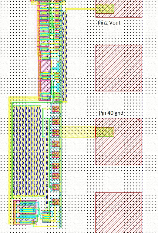
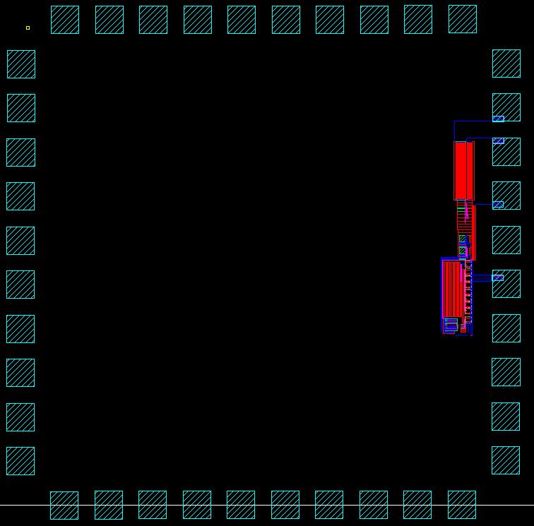
24 Fig. 32 Fig. 33
25 Pin Diagram The Synchronous Buck Converter pin diagram is displayed below in Figure 32. The pins are connected as follows: o Pin 40- gnd o Pin 2 - Vout o Pin 3 - Out o Pin 4 - vdd Fig Conclusion The CMOS switching power supply design was initially a seemingly difficult project that required the correlation of topics covered during the duration of the course. There were numerous failures throughout the design process that assisted in learning and creating a moderately functioning design. The project also provided an opportunity to analyze my strengths and weaknesses as a designer and to learn from the mistakes made during the design process. Despite these mistakes and failures, a successfully functioning Synchronous Buck Converter that meets required specifications as outlined in the project parameters was designed and is presented for evaluation.
26 Index Simulation File Reference Page 1. sim_syncbuckconv_em_f16 - parametric analysis with variables current load, Il, VDD, and temperature using file sim1.il. 2. sim2_syncbuckconv_em_f16 - parametric analysis with variables VDD, and temperature and a pulsed current load using file sim2.il. 3. sim_efficiency_syncbuckconv_em_f16 - parametric analysis for collecting data points to plot efficiency for varying loads and VDD. Uses parametric analysis file sim_efficiency.il with results in file efficiency_excel.csv. 4. sim_bandgap = simulation showing bandgap voltage reference and temperature effects. 5. sim_comp_buff = simulation showing switching point for 12u/6u inverter in buffer stage 6. sim_switchptbuff = simulation showing switching point adjustment out of comparator 7. sim_temp_bandgap = demonstrated temperature variations in bandgap 8. sim_temp_bandgap2= parametric analysis demonstrating bandgap operation for variations in temperature and VDD 9. sim_comparator_em_f16 = simulations demonstrating comparator operation
CMOS synchronous Buck switching power supply Raheel Sadiq November 28, 2016
 CMOS synchronous Buck switching power supply Raheel Sadiq November 28, 2016 Part 1: This part of the project is to lay out a bandgap. We previously built our bandgap in HW #13 which supplied a constant
Short Channel Bandgap Voltage Reference
 Short Channel Bandgap Voltage Reference EE-584 Final Report Authors: Thymour Legba Yugu Yang Chris Magruder Steve Dominick Table of Contents Table of Figures... 3 Abstract... 4 Introduction... 5 Theory
NOVEMBER 29, 2017 COURSE PROJECT: CMOS TRANSIMPEDANCE AMPLIFIER ECG 720 ADVANCED ANALOG IC DESIGN ERIC MONAHAN
 NOVEMBER 29, 2017 COURSE PROJECT: CMOS TRANSIMPEDANCE AMPLIFIER ECG 720 ADVANCED ANALOG IC DESIGN ERIC MONAHAN 1.Introduction: CMOS Transimpedance Amplifier Avalanche photodiodes (APDs) are highly sensitive,
Analog CMOS Interface Circuits for UMSI Chip of Environmental Monitoring Microsystem
 Analog CMOS Interface Circuits for UMSI Chip of Environmental Monitoring Microsystem A report Submitted to Canopus Systems Inc. Zuhail Sainudeen and Navid Yazdi Arizona State University July 2001 1. Overview
UMAINE ECE Morse Code ROM and Transmitter at ISM Band Frequency
 UMAINE ECE Morse Code ROM and Transmitter at ISM Band Frequency Jamie E. Reinhold December 15, 2011 Abstract The design, simulation and layout of a UMAINE ECE Morse code Read Only Memory and transmitter
An Analog Phase-Locked Loop
 1 An Analog Phase-Locked Loop Greg Flewelling ABSTRACT This report discusses the design, simulation, and layout of an Analog Phase-Locked Loop (APLL). The circuit consists of five major parts: A differential
A Variable-Frequency Parallel I/O Interface with Adaptive Power Supply Regulation
 WA 17.6: A Variable-Frequency Parallel I/O Interface with Adaptive Power Supply Regulation Gu-Yeon Wei, Jaeha Kim, Dean Liu, Stefanos Sidiropoulos 1, Mark Horowitz 1 Computer Systems Laboratory, Stanford
EE584 Introduction to VLSI Design Final Project Document Group 9 Ring Oscillator with Frequency selector
 EE584 Introduction to VLSI Design Final Project Document Group 9 Ring Oscillator with Frequency selector Group Members Uttam Kumar Boda Rajesh Tenukuntla Mohammad M Iftakhar Srikanth Yanamanagandla 1 Table
DESIGN AND SIMULATION OF A HIGH PERFORMANCE CMOS VOLTAGE DOUBLERS USING CHARGE REUSE TECHNIQUE
 Journal of Engineering Science and Technology Vol. 12, No. 12 (2017) 3344-3357 School of Engineering, Taylor s University DESIGN AND SIMULATION OF A HIGH PERFORMANCE CMOS VOLTAGE DOUBLERS USING CHARGE
ML4818 Phase Modulation/Soft Switching Controller
 Phase Modulation/Soft Switching Controller www.fairchildsemi.com Features Full bridge phase modulation zero voltage switching circuit with programmable ZV transition times Constant frequency operation
Features MIC2193BM. Si9803 ( 2) 6.3V ( 2) VDD OUTP COMP OUTN. Si9804 ( 2) Adjustable Output Synchronous Buck Converter
 6.3V ( 2) VDD OUTP COMP OUTN. Si9804 ( 2) Adjustable Output Synchronous Buck Converter") MIC2193 4kHz SO-8 Synchronous Buck Control IC General Description s MIC2193 is a high efficiency, PWM synchronous buck control IC housed in the SO-8 package. Its 2.9V to 14V input voltage range allows
MIC2193 4kHz SO-8 Synchronous Buck Control IC General Description s MIC2193 is a high efficiency, PWM synchronous buck control IC housed in the SO-8 package. Its 2.9V to 14V input voltage range allows
Engineer-to-Engineer Note
 Engineer-to-Engineer Note EE-339 a Technical notes on using Analog Devices DSPs, processors and development tools Visit our Web resources http://www.analog.com/ee-notes and http://www.analog.com/processors
CMOS Digital Integrated Circuits Lec 11 Sequential CMOS Logic Circuits
 Lec Sequential CMOS Logic Circuits Sequential Logic In Combinational Logic circuit Out Memory Sequential The output is determined by Current inputs Previous inputs Output = f(in, Previous In) The regenerative
AUR MHz, 1A, Step-Down DC-DC Converter. Features. Description. Applications. Package Information. Order Information
 1.5MHz, 1A, Step-Down DC-DC Converter Features High efficiency Buck Power Converter Low Quiescent Current 1A Output Current Adjustable Output Voltage from 1V to 3.3V Wide Operating Voltage Ranges : 2.5
C1 1uF. C3 100pF Q1 IRLML5203 ISEN R Figure 1 - Typical application of IRU3065 for single input voltage. PACKAGE ORDER INFORMATION
 FEATURES Generate Negative Output from +V Input A Maximum Output Current.MHz maximum Switching Frequency Few External Components Available in -Pin SOT- APPLICATIONS Hard Disk Drives Blue Laser for DVD
Electronic Circuits EE359A
 Electronic Circuits EE359A Bruce McNair B206 bmcnair@stevens.edu 201-216-5549 1 Memory and Advanced Digital Circuits - 2 Chapter 11 2 Figure 11.1 (a) Basic latch. (b) The latch with the feedback loop opened.
1MHz, 3A Synchronous Step-Down Switching Voltage Regulator
 FEATURES Guaranteed 3A Output Current Efficiency up to 94% Efficiency up to 80% at Light Load (10mA) Operate from 2.8V to 5.5V Supply Adjustable Output from 0.8V to VIN*0.9 Internal Soft-Start Short-Circuit
MP2497-A 3A, 50V, 100kHz Step-Down Converter with Programmable Output OVP Threshold
 The Future of Analog IC Technology MP2497-A 3A, 50V, 100kHz Step-Down Converter with Programmable Output OVP Threshold DESCRIPTION The MP2497-A is a monolithic step-down switch mode converter with a programmable
Ordering Information Type Number PXXX Package Type: MR:SOT23 M5:SOT23-5 PR:SOT89-3 TB: TO92 Output Voltage: 25:2.5V 26:2.6V 36:3.6V Package Marking CX
 General Description The Series are synchronous PFM step-up DC-DC converters with very low ripple noise due to the high operating frequency, and the maximum operating frequency is 300KHz. The output voltages
DESCRIPTION FEATURES APPLICATIONS TYPICAL APPLICATION. 500KHz, 18V, 2A Synchronous Step-Down Converter
 DESCRIPTION The is a fully integrated, high-efficiency 2A synchronous rectified step-down converter. The operates at high efficiency over a wide output current load range. This device offers two operation
Liteon Semiconductor Corporation LSP MHZ, 600mA Synchronous Step-Up Converter
 FEATURES High Efficiency: Up to 96% 1.2MHz Constant Switching Frequency 3.3V Output Voltage at Iout=100mA from a Single AA Cell; 3.3V Output Voltage at Iout=400mA from two AA cells Low Start-up Voltage:
EUP V/12V Synchronous Buck PWM Controller DESCRIPTION FEATURES APPLICATIONS. Typical Application Circuit. 1
 5V/12V Synchronous Buck PWM Controller DESCRIPTION The is a high efficiency, fixed 300kHz frequency, voltage mode, synchronous PWM controller. The device drives two low cost N-channel MOSFETs and is designed
XM5202/XM5202F. 2A 1.5MHz Synchronous Step-Down DC/DC Converter GENERAL DESCRIPTION APPLICATIONS FEATURES
 2A 1.5MHz Synchronous Step-Down DC/DC Converter GENERAL DESCRIPTION The XM5202/5202F synchronous buck converter is a high frequency step-down voltage regulator with current control mode. It can output
1MHz, 3A Synchronous Step-Down Switching Voltage Regulator
 FEATURES Guaranteed 3A Output Current Efficiency up to 95% Operate from 2.8V to 5.5V Supply Adjustable Output from 0.8V to VIN*0.86 Internal Soft-Start Short-Circuit and Thermal -Overload Protection 1MHz
SGM V Step-Up LED Driver
 GENERAL DESCRIPTION The SGM3725 is a versatile constant current LED driver with a high efficiency step-up converter architecture. Unique technology and high 1.35A current limit allow SGM3725 to drive up
B.E. SEMESTER III (ELECTRICAL) SUBJECT CODE: X30902 Subject Name: Analog & Digital Electronics
 SUBJECT CODE: X30902 Subject Name: Analog & Digital Electronics") B.E. SEMESTER III (ELECTRICAL) SUBJECT CODE: X30902 Subject Name: Analog & Digital Electronics Sr. No. Date TITLE To From Marks Sign 1 To verify the application of op-amp as an Inverting Amplifier 2 To
B.E. SEMESTER III (ELECTRICAL) SUBJECT CODE: X30902 Subject Name: Analog & Digital Electronics Sr. No. Date TITLE To From Marks Sign 1 To verify the application of op-amp as an Inverting Amplifier 2 To
RT9266B. Tiny Package, High Efficiency, Step-Up DC/DC Converter. General Description. Features. Applications. Ordering Information RT9266B
 Tiny Package, High Efficiency, Step-Up DC/DC Converter General Description The RT9266B is a compact, high efficiency, and low voltage step-up DC/DC converter with an Adaptive Current Mode PWM control loop,
FP6276B 500kHz 6A High Efficiency Synchronous PWM Boost Converter
 500kHz 6A High Efficiency Synchronous PWM Boost Converter General Description The is a current mode boost DC-DC converter with PWM/PSM control. Its PWM circuitry with built-in 40mΩ high side switch and
HIGH LOW Astable multivibrators HIGH LOW 1:1
 1. Multivibrators A multivibrator circuit oscillates between a HIGH state and a LOW state producing a continuous output. Astable multivibrators generally have an even 50% duty cycle, that is that 50% of
SGM3736 PWM Dimming, 38V Step-Up LED Driver
 GENERAL DESCRIPTION The SGM3736 is a versatile constant current LED driver with a high efficiency step-up converter architecture. The low-side power MOSFET is integrated in the device, significantly shrinking
1.5MHz, 800mA, High-Efficiency PWM Synchronous Step-Down Converter
 1.5MHz, 800mA, High-Efficiency PWM Synchronous Step-Down Converter Description The is a high efficiency, low-noise, DC-DC step-down pulse width modulated (PWM) converter that goes automatically into PFM
CHAPTER 6 PHASE LOCKED LOOP ARCHITECTURE FOR ADC
 138 CHAPTER 6 PHASE LOCKED LOOP ARCHITECTURE FOR ADC 6.1 INTRODUCTION The Clock generator is a circuit that produces the timing or the clock signal for the operation in sequential circuits. The circuit
LM13600 Dual Operational Transconductance Amplifiers with Linearizing Diodes and Buffers
 LM13600 Dual Operational Transconductance Amplifiers with Linearizing Diodes and Buffers General Description The LM13600 series consists of two current controlled transconductance amplifiers each with
EE 42/100 Lecture 23: CMOS Transistors and Logic Gates. Rev A 4/15/2012 (10:39 AM) Prof. Ali M. Niknejad
 Prof. Ali M. Niknejad") A. M. Niknejad University of California, Berkeley EE 100 / 42 Lecture 23 p. 1/16 EE 42/100 Lecture 23: CMOS Transistors and Logic Gates ELECTRONICS Rev A 4/15/2012 (10:39 AM) Prof. Ali M. Niknejad University
A. M. Niknejad University of California, Berkeley EE 100 / 42 Lecture 23 p. 1/16 EE 42/100 Lecture 23: CMOS Transistors and Logic Gates ELECTRONICS Rev A 4/15/2012 (10:39 AM) Prof. Ali M. Niknejad University
FP kHz 7A High Efficiency Synchronous PWM Boost Converter
 500kHz 7A High Efficiency Synchronous PWM Boost Converter General Description The FP6277 is a current mode boost DC-DC converter with PWM/PSM control. Its PWM circuitry with built-in 30mΩ high side switch
Design Consideration with AP3041
 Design Consideration with AP3041 Application Note 1059 Prepared by Yong Wang System Engineering Dept. 1. Introduction The AP3041 is a current-mode, high-voltage low-side channel MOSFET controller, which
ANP012. Contents. Application Note AP2004 Buck Controller
 Contents 1. AP004 Specifications 1.1 Features 1. General Description 1. Pin Assignments 1.4 Pin Descriptions 1.5 Block Diagram 1.6 Absolute Maximum Ratings. Hardware.1 Introduction. Typical Application.
MP A, 55V, 100kHz Step-Down Converter with Programmable Output OVP Threshold
 The Future of Analog IC Technology MP24943 3A, 55V, 100kHz Step-Down Converter with Programmable Output OVP Threshold DESCRIPTION The MP24943 is a monolithic, step-down, switch-mode converter. It supplies
Charge Pump Voltage Converters TJ7660
 FEATURES Simple Conversion of +5V Logic Supply to ±5V Supplies Simple Voltage Multiplication (VOUT = (-) nvin) Typical Open Circuit Voltage Conversion Efficiency 99.9% Typical Power Efficiency 98% Wide
EM5812/A. 12A 5V/12V Step-Down Converter. Applications. General Description. Pin Configuration. Ordering Information. Typical Application Circuit
 12A 5V/12V Step-Down Converter General Description is a synchronous rectified PWM controller with a built in high-side power MOSFET operating with 5V or 12V supply voltage. It achieves 10A continuous output
AIC1340 High Performance, Triple-Output, Auto- Tracking Combo Controller
 High Performance, Triple-Output, Auto- Tracking Combo Controller FEATURES Provide Triple Accurate Regulated Voltages Optimized Voltage-Mode PWM Control Dual N-Channel MOSFET Synchronous Drivers Fast Transient
HM V~5V Input 12W Output Step-up DC/DC Converter GENERAL DESCRIPTION FEATURES APPLICATIONS
 3.3V~5V Input 12W Output Step-up DC/DC Converter GENERAL DESCRIPTION The HM9226 is a high frequency, high efficiency DC to DC converter with an integrated 6A, 40mÙ power switch capable of providing an
ACT111A. 4.8V to 30V Input, 1.5A LED Driver with Dimming Control GENERAL DESCRIPTION FEATURES APPLICATIONS TYPICAL APPLICATION CIRCUIT
 4.8V to 30V Input, 1.5A LED Driver with Dimming Control FEATURES Up to 92% Efficiency Wide 4.8V to 30V Input Voltage Range 100mV Low Feedback Voltage 1.5A High Output Capacity PWM Dimming 10kHz Maximum
23V, 2A, 600KHz Asynchronous Synchronous Step-Down DC/DC Converter
 23V, 2A, 600KHz Asynchronous Synchronous StepDown DC/DC Converter Description The is a monolithic stepdown switch mode converter with a builtin power MOSFET. It achieves 2A output current over a wide input
MP A, 24V, 1.4MHz Step-Down Converter
 The Future of Analog IC Technology DESCRIPTION The MP8368 is a monolithic step-down switch mode converter with a built-in internal power MOSFET. It achieves 1.8A continuous output current over a wide input
HY2596A 3A 150kHz DC-DC BUCK REGULATOR
 Description of regulators provides all the active functions for a step-down (buck) switching regulator, and drives 3A load with excellent line and load regulation. is available in fixed output voltages
ADT7350. General Description. Applications. Features. Typical Application Circuit. Aug / Rev. 0.
 General Description The ADT7350 is a step-down converter with integrated switching MOSFET. It operates wide input supply voltage range from 4.5V to 24V with 1.2A peak output current. It includes current
PURPOSE: NOTE: Be sure to record ALL results in your laboratory notebook.
 EE4902 Lab 9 CMOS OP-AMP PURPOSE: The purpose of this lab is to measure the closed-loop performance of an op-amp designed from individual MOSFETs. This op-amp, shown in Fig. 9-1, combines all of the major
MP A, 24V, 700KHz Step-Down Converter
 The Future of Analog IC Technology MP2371 1.8A, 24V, 700KHz Step-Down Converter DESCRIPTION The MP2371 is a monolithic step-down switch mode converter with a built-in internal power MOSFET. It achieves
CHAPTER 5 DESIGN AND ANALYSIS OF COMPLEMENTARY PASS- TRANSISTOR WITH ASYNCHRONOUS ADIABATIC LOGIC CIRCUITS
 70 CHAPTER 5 DESIGN AND ANALYSIS OF COMPLEMENTARY PASS- TRANSISTOR WITH ASYNCHRONOUS ADIABATIC LOGIC CIRCUITS A novel approach of full adder and multipliers circuits using Complementary Pass Transistor
ADT7350. General Description. Features. Applications. Typical Application Circuit. Sep / Rev. 0.
 General Description The ADT7350 is a step-down converter with integrated switching MOSFET. It operates wide input supply voltage range from 4.5V to 24V with 1.2A peak output current. It includes current
LN2402. PWM/PFM Automatic Switching Controlled Synchronous DC-DC Converters. General Description. Applications. Package. Features
 PWM/PFM Automatic Switching Controlled Synchronous DC-DC Converters General Description The is a constant frequency, current mode step-down converter. It is ideal for powering portable equipment that runs
A8133 HIGH EFFICIENCY, HIGH POWER WHITE LED DRIVER 1MHz FREQUENCY, INTERNAL 2A MOSFET SWITCH
 DESCRIPTION The is a boost DC-DC converter that delivers a regulated output current. The switches at a 1.0MHz constant frequency, allowing for the use of small value external inductor and ceramic capacitors.
DS1267B Dual Digital Potentiometer
 Dual Digital Potentiometer FEATURES Two digitally controlled, 256-position potentiometers Serial port provides means for setting and reading both potentiometers Resistors can be connected in series to
Final Report. May 5, Contract: N M Prepared for: Dr. Ignacio Perez. Office of Naval Research. 800 N.
 Signal Sciences, Inc.Phone 585-275-4879 1800 Bri-Hen Townline Road Fax 585-273-4919 Rochester, New York 14623Web www.signalsciences.com Ultra-low Power Sentry for Ambient Powered Smart Sensors Final Report
BL8028 FEATURES DESCRIPTION APPLICATIONS TYPICAL APPLICATION PIN OUT & MARKING. 1.5A 2MHz 6V Synchronous Buck Converter
 1.5A 2MHz 6V Synchronous Buck Converter DESCRIPTION The BL8028 is a high-efficiency, DC to DC step-down switching regulators, capable of delivering up to 1.5A of output current. The device operates from
MIC38C42A/43A/44A/45A
 MIC38C42A/43A/44A/45A BiCMOS Current-Mode PWM Controllers General Description The MIC38C4xA are fixed frequency, high performance, current-mode PWM controllers. Micrel s BiCMOS devices are pin compatible
RT9266B Tiny Package, High Efficiency, Step-up DC/DC Converter General Description Features 1.0V Low Start-up Input Voltage at 1mA Load
 查询 RT9266 供应商 Tiny Package, High Efficiency, Step-up DC/DC Converter General Description The is a compact, high efficiency, and low voltage step-up DC/DC converter with an Adaptive Current Mode PWM control
CMOS Digital Integrated Circuits Analysis and Design
 CMOS Digital Integrated Circuits Analysis and Design Chapter 8 Sequential MOS Logic Circuits 1 Introduction Combinational logic circuit Lack the capability of storing any previous events Non-regenerative
PWM Step-Up DC/DC Converter for Panel Backlight. Features. Fig. 1
 PWM Step-Up DC/DC Converter for Panel Backlight General Description The designed with high efficiency step up DC/DC converter for driving white LEDs. The device can drive up 11 white LEDs from a single
RT Channel DC/DC Converters IC with High-Efficiency Step-up and Step-down. Preliminary. Features. General Description
 4 Channel DC/DC Converters IC with High-Efficiency Step-up and Step-down General Description The is a complete power-supply solution for digital still cameras and other hand-held devices. It integrates
MP2494 2A, 55V, 100kHz Step-Down Converter
 The Future of Analog IC Technology MP2494 2A, 55V, 100kHz Step-Down Converter DESCRIPTION The MP2494 is a monolithic step-down switch mode converter. It achieves 2A continuous output current over a wide
MP2314 High Efficiency 2A, 24V, 500kHz Synchronous Step Down Converter
 The Future of Analog IC Technology MP2314 High Efficiency 2A, 24V, 500kHz Synchronous Step Down Converter DESCRIPTION The MP2314 is a high frequency synchronous rectified step-down switch mode converter
MP V, 1.2A, 1.4MHz White LED Driver Buck/Boost Halogen Replacement
 The Future of Analog IC Technology DESCRIPTION The MP81 is a 36V,1.A,white LED driver suitable for either step-down or inverting step-up/down applications. It achieves 1.A peak output current over a wide
23V, 3A, 340KHz Synchronous Step-Down DC/DC Converter
 23V, 3A, 340KHz Synchronous Step-Down DC/DC Converter Description The is a synchronous step-down DC/DC converter that provides wide 4.5V to 23V input voltage range and 3A continuous load current capability.
DS1868B Dual Digital Potentiometer
 www. maximintegrated.com FEATURES Two digitally controlled, 256-position potentiometers Serial port provides means for setting and reading both potentiometers Resistors can be connected in series to provide
ANP030. Contents. Application Note AP2014/A Synchronous PWM Controller. 1. AP2014/A Specification. 2. Hardware. 3. Design Procedure. 4.
 Contents 1. AP2014/A Specification 1.1 Features 1.2 General Description 1.3 Pin Assignments 1.4 Pin Descriptions 1.5 Block Diagram 1.6 Absolute Maximum Ratings 2. Hardware 2.1 Introduction 2.2 Description
MIC4421/4422. Bipolar/CMOS/DMOS Process. General Description. Features. Applications. Functional Diagram. 9A-Peak Low-Side MOSFET Driver
 9A-Peak Low-Side MOSFET Driver Micrel Bipolar/CMOS/DMOS Process General Description MIC4421 and MIC4422 MOSFET drivers are rugged, efficient, and easy to use. The MIC4421 is an inverting driver, while
CEP8113A Rev 2.0, Apr, 2014
 Wide-Input Sensorless CC/CV Step-Down DC/DC Converter FEATURES 42V Input Voltage Surge 40V Steady State Operation Up to 3.5A output current Output Voltage 2.5V to 10V Resistor Programmable Current Limit
SUMMARY/DIALOGUE 2 PRESHAPE PIXEL OVERVIEW 3 BRIEF OPERATING INSTRUCTIONS 3 PRESHAPE PIXEL SIMULATION: EXAMPLE OPERATION 4 PRESHAPE PIXEL SIMULATION:
 SUMMARY/DIALOGUE 2 PRESHAPE PIXEL OVERVIEW 3 BRIEF OPERATING INSTRUCTIONS 3 PRESHAPE PIXEL SIMULATION: EXAMPLE OPERATION 4 PRESHAPE PIXEL SIMULATION: SMALL SIGNALS AROUND THRESHOLD 5 PRESHAPE PIXEL SIMULATION:
Features MIC2194BM VIN EN/ UVLO CS OUTP VDD FB. 2k COMP GND. Adjustable Output Buck Converter MIC2194BM UVLO
 MIC2194 400kHz SO-8 Buck Control IC General Description s MIC2194 is a high efficiency PWM buck control IC housed in the SO-8 package. Its 2.9V to 14V input voltage range allows it to efficiently step
EM5301. Pin Assignment
 5V/2V Synchronous Buck PWM Controller General Description is a synchronous rectified PWM controller operating with 5V or 2V supply voltage. This device operates at 200/300/500 khz and provides an optimal
Built-In OVP White LED Step-up Converter in Tiny Package
 Built-In White LED Step-up Converter in Tiny Package Description The is a step-up DC/DC converter specifically designed to drive white LEDs with a constant current. The device can drive up to 4 LEDs in
PL2733A PULAN TECHNOLOGY CO., LIMITED. to 30V. regulator from. and line regulation. programmable synchronous. current limit and.
 Wide Range Synchronous Buck Controller Features Wide Input Voltage Range: 8V to 30V Up to 93% Efficiency Programmable Switching Frequency up to up to 500kHz No Loop Compensation Required Programmable current
DS1867 Dual Digital Potentiometer with EEPROM
 Dual Digital Potentiometer with EEPROM www.dalsemi.com FEATURES Nonvolatile version of the popular DS1267 Low power consumption, quiet, pumpless design Operates from single 5V or ±5V supplies Two digitally
PACKAGE REFERENCE. ELECTRICAL CHARACTERISTICS V IN = 12V, T A = +25 C, unless otherwise noted.
 PACKAGE REFERENCE TOP VIEW TOP VIEW BST 1 SW BST 1 SW GND 2 5 GND 2 5 FB 3 EN FB 3 EN MP2259_PD01_TSOT23 MP2259_PD02_SOT23 Part Number* Package Temperature MP2259DJ TSOT23-0 C to 85 C * For Tape & Reel,
WD3119 WD3119. High Efficiency, 40V Step-Up White LED Driver. Descriptions. Features. Applications. Order information 3119 FCYW 3119 YYWW
 High Efficiency, 40V Step-Up White LED Driver Http//:www.sh-willsemi.com Descriptions The is a constant current, high efficiency LED driver. Internal MOSFET can drive up to 10 white LEDs in series and
TFT-LCD DC/DC Converter with Integrated Backlight LED Driver
 TFT-LCD DC/DC Converter with Integrated Backlight LED Driver Description The is a step-up current mode PWM DC/DC converter (Ch-1) built in an internal 1.6A, 0.25Ω power N-channel MOSFET and integrated
180KHz, 5A Step-down Converter With Cable Dropout Compensation
 180KHz, 5A Step-down Converter With Cable Dropout Compensation General Description The is a compact, high efficiency, high speed synchronous monolithic step-down switching regulator designed to power 5V
SR A, 30V, 420KHz Step-Down Converter DESCRIPTION FEATURES APPLICATIONS TYPICAL APPLICATION
 SR2026 5A, 30V, 420KHz Step-Down Converter DESCRIPTION The SR2026 is a monolithic step-down switch mode converter with a built in internal power MOSFET. It achieves 5A continuous output current over a
Boundary Mode Offline LED Driver Using MP4000. Application Note
 The Future of Analog IC Technology AN046 Boundary Mode Offline LED Driver Using MP4000 Boundary Mode Offline LED Driver Using MP4000 Application Note Prepared by Zheng Luo March 25, 2011 AN046 Rev. 1.0
1.5MHz 800mA, Synchronous Step-Down Regulator. Features. Applications. 2.2 uh. Cout 10uF CER. Cin 4.7 uf CER 2 GND FIG.1
 1.5MHz 800mA, Synchronous Step-Down Regulator General Description is designed with high efficiency step down DC/DC converter for portable devices applications. It features with extreme low quiescent current
MP V to 5.5V Input, 1.2MHz, Dual-ch LCD Bias Power Supply
 MP5610 2.7V to 5.5V Input, 1.2MHz, Dual-ch LCD Bias Power Supply DESCRIPTION The MP5610 is a dual-output converter with 2.7V-to-5.5V input for small size LCD panel bias supply. It uses peak-current mode
HM2259D. 2A, 4.5V-20V Input,1MHz Synchronous Step-Down Converter. General Description. Features. Applications. Package. Typical Application Circuit
 HM2259D 2A, 4.5V-20V Input,1MHz Synchronous Step-Down Converter General Description Features HM2259D is a fully integrated, high efficiency 2A synchronous rectified step-down converter. The HM2259D operates
10-Bit µp-compatible D/A converter
 DESCRIPTION The is a microprocessor-compatible monolithic 10-bit digital-to-analog converter subsystem. This device offers 10-bit resolution and ±0.1% accuracy and monotonicity guaranteed over full operating
HM V 2A 500KHz Synchronous Step-Down Regulator
 Features HM8114 Wide 4V to 30V Operating Input Range 2A Continuous Output Current Fixed 500KHz Switching Frequency No Schottky Diode Required Short Protection with Hiccup-Mode Built-in Over Current Limit
A PROCESS AND TEMPERATURE COMPENSATED RING OSCILLATOR
 A PROCESS AND TEMPERATURE COMPENSATED RING OSCILLATOR Yang-Shyung Shyu * and Jiin-Chuan Wu Dept. of Electronics Engineering, National Chiao-Tung University 1001 Ta-Hsueh Road, Hsin-Chu, 300, Taiwan * E-mail:
Lecture 16. Complementary metal oxide semiconductor (CMOS) CMOS 1-1
 CMOS 1-1") Lecture 16 Complementary metal oxide semiconductor (CMOS) CMOS 1-1 Outline Complementary metal oxide semiconductor (CMOS) Inverting circuit Properties Operating points Propagation delay Power dissipation
Lecture 16 Complementary metal oxide semiconductor (CMOS) CMOS 1-1 Outline Complementary metal oxide semiconductor (CMOS) Inverting circuit Properties Operating points Propagation delay Power dissipation
Controller for RF Power Amplifier Boost Converter
 Controller for RF Power Amplifier Boost Converter Si9160 FEATURES High Frequency Switching (up to 2 MHz) Optimized Output Drive Current (350 ma) Standby Mode Wide Bandwidth Feedback Amplifier Single-Cell
ENEE307 Lab 7 MOS Transistors 2: Small Signal Amplifiers and Digital Circuits
 ENEE307 Lab 7 MOS Transistors 2: Small Signal Amplifiers and Digital Circuits In this lab, we will be looking at ac signals with MOSFET circuits and digital electronics. The experiments will be performed
MP A, 50V, 1.2MHz Step-Down Converter in a TSOT23-6
 MP2456 0.5A, 50V, 1.2MHz Step-Down Converter in a TSOT23-6 DESCRIPTION The MP2456 is a monolithic, step-down, switchmode converter with a built-in power MOSFET. It achieves a 0.5A peak-output current over
Constant Current Switching Regulator for White LED
 Constant Current Switching Regulator for White LED FP7201 General Description The FP7201 is a Boost DC-DC converter specifically designed to drive white LEDs with constant current. The device can support
G MHz 1A Synchronous Step-Down Regulator. Features High Efficiency: Up to 93% Low Quiescent Current: Only 50µA During Operation
 MHz A Synchronous Step-Down Regulator Features High Efficiency: Up to 93% Low Quiescent Current: Only 5µA During Operation Internal Soft Start Function A Output Current.5V to 6V Input Voltage Range MHz
1.5MHz, 2A Synchronous Step-Down Regulator
 1.5MHz, 2A Synchronous Step-Down Regulator General Description The is a high efficiency current mode synchronous buck PWM DC-DC regulator. The internal generated 0.6V precision feedback reference voltage
Advance Information. Conditions < ±4% < ±6% I OUT = 10 ma to 60 ma, V DS = 0.6V < ±6% < ±12% I OUT = 60 ma to100 ma, V DS = 0.8V
 Features Macroblock Advance Information CN 5001CN MBI5001CN 8 constant-current output channels Constant output current invariant to load voltage change Excellent output current accuracy: between channels:
MIC4414/4415. General Description. Features. Applications. Typical Application. 1.5A, 4.5V to 18V, Low-Side MOSFET Driver
 MIC4414/4415 1.5A, 4.5V to 18V, Low-Side MOSFET Driver General Description The MIC4414 and MIC4415 are low-side MOSFET drivers designed to switch an N-channel enhancement type MOSFET in low-side switch
1.5MHz, 3A Synchronous Step-Down Regulator
 1.5MHz, 3A Synchronous Step-Down Regulator FP6165 General Description The FP6165 is a high efficiency current mode synchronous buck PWM DC-DC regulator. The internal generated 0.6V precision feedback reference
Pin Assignment and Description TOP VIEW PIN NAME DESCRIPTION 1 GND Ground SOP-8L Absolute Maximum Ratings (Note 1) 2 CS Current Sense
 2 CS Current Sense") HX1336 Wide Input Range Synchronous Buck Controller Features Description Wide Input Voltage Range: 8V ~ 30V Up to 93% Efficiency No Loop Compensation Required Dual-channeling CC/CV control Cable drop Compensation
HX1336 Wide Input Range Synchronous Buck Controller Features Description Wide Input Voltage Range: 8V ~ 30V Up to 93% Efficiency No Loop Compensation Required Dual-channeling CC/CV control Cable drop Compensation
UM mA, 600kHz Step-Up DC-DC Converter UM3433 SOT23-6. General Description. Rev.05 Dec /9
 General Description UM3433 600mA, 600kHz Step-Up DC-DC Converter UM3433 SOT23-6 The UM3433 is synchronous rectified, fixed frequency, step-up DC/DC converter series delivering high efficiency in a low
RT9285A/B. Tiny Package, High Performance, Diode Embedded White LED Driver. Preliminary. Features. General Description.
 General Description The RT9285 is a high frequency asynchronous boost converter with internal diode, which can support 2 to 5 White LEDs for backlighting and OLED power supply. The Internal soft start