WJ 8617B and 8618B 10 KHz IF Bandwidth Upgrade By: Stephen Pappin
|
|
|
- Marylou Harper
- 5 years ago
- Views:
Transcription
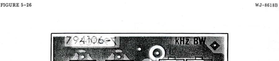
1 WJ 8617B and 8618B 10 KHz IF Bandwidth Upgrade By: Stephen Pappin Many early 8617Bs and 8618Bs were configured with 20 KHz IF filters in bandwidth position 1. This bandwidth is suitable for A9W Composite Emissions but not for A3E or F3E Emissions. A 10 KHz band width is useful for FM land mobile reception or as a roofing filter for SSB operation. It is possible to field upgrade the radios for use with narrower filters. The 8617B / 8618B 10 KHz upgrade is fairly straight forward. Two methods of upgrade are explained, a simple board swap and modifications to the existing boards. Board Swap: The board swap requires replacing the 20 KHz boards and the associated front panel BW key with 10 KHz hardware. The board swap DOES NOT REQUIRE alignment. Modification: Modification of the original 20 KHz boards REQUIRES re-alignment of the associated boards. It does not require a complete re-alignment of the receiver. Manuals, tools, and test equipment should be obtained prior to performing any work. THE MANUAL IS REQUIRED. Do not attempt this modification without it! This procedure focuses on the modification of 20 KHz IF Amplifier and FM Demodulator boards. Materials Required Board Swap: Replace the 20 KHz boards, , , and 20 KHz BW key. Install: , 10 KHz IF Amplifier board (A3A17 on page 4) , 10 KHz FM Demodulator board (A3A9 on page 5) 10 KHz front panel push button BW key (pry the 20 KHz key off with a plastic non marking tool) Modification: Modify an Existing 20 KHz board set Recommended and required materials Manual: WJ-8617B or WJ-8618B manual 1984 edition - required De Soldering Tool: 100W de-soldering tool with proper tips Extender Cards: Desirable - not required Manual Pages: (see the attached pages for manual figures and numbers) Test Equipment: Please consult the alignment procedures in the manual - required a , 20 KHz IF Amplifier board (A3A9 on page 4) FL1: 92001, 10 KHz Crystal Filter, 3:1 shape factor R18: CF1/4-100 OHMS/J, 100 Ohm resistor, ¼ W, metal film resistor R20: CF1/4-3.3K/J, 3.3K Ohm resistor, ¼ W, metal film resistor b , 20 KHz FM Demodulator board (A3A17 on page 5) L4: , 22mH inductor L5: , 15mH inductor C6: U2J0-150J, 15pF silver mica or ceramic capacitor C17: CK06BX683K, 0.068uF film or molded ceramic capacitor R2: RN55C2371F, 2.37K Ohm, 1/10 W, metal film resistor R3: RN55C1371F, 1.37K Ohm, 1/10 W, metal film resistor c. 10 KHz front panel push button BW key
2 Upgrades Board Swap: No additional work is required. Turn on the radio and verify operation. Modification: A vacuum de-soldering tool with adjustable heat ranges is highly recommended for component removal. Be careful, work slowly, and avoid damaging the PC boards. On large ground planes a hot air leveling tool can be used to re flow solder to regain the original factory look. Verify your modifications prior to clean up. Alignment will be required before performance tests can be run. a , 20 KHz IF Amplifier board (A3A9 on page 4) Remove R11 Replace R18 with a 100 Ohm resistor Replace R20 with a 3.3K Ohm resistor Replace the 20 KHz filter can p/n with the 10 KHz filter can p/n Change the board designation to -1 b , 20 KHz FM Demodulator board (A3A17 on page 5) Replace L4 with a 22mH inductor Replace L5 with a 15mH inductor Replace C6 with a silver mica or ceramic capacitor Replace C17 with a 0.068uF film or molded ceramic capacitor Replace R2 with a 2.37K Ohm, 1/10 W, metal film resistor Replace R3 with a 1.37K Ohm, 1/10 W, metal film resistor Change the board designation to -1 c. Install the 10 KHz front panel BW key in position one Alignment The 8617B / 8618B Manual defines the required equipment and procedures for alignment. Please refer to the following pages in the 8617B / 8618B manual: a. Page 4-44, IF Amplifier (A3A9 through A3A13) Alignment b. Page 4-50, FM Demodulator (A3A17 through A3A21) Alignment The alignment can be performed without using extender cards, but it is much easier to perform with extender cards. To align the boards without using extender cards simply remove all of the boards to the right of the card you are working on. This allows enough room for flexible nylon tools to be used to make adjustments. Notes: a. IF Amplifier BW Code: On the work bench use a lab power supply to preset the new boards BW code voltage to 1.0V. Install the 10 KHz IF Amplifier board in position one. b. Without Extenders (as seen from the front of the receiver): Remove all boards to the right of the boards being aligned. The 10 KHz boards should be installed in the far left positions. c. Install 1 spacers under the receiver and remove the top cover to allow convection cooling. d. Allow the receiver to warm up for several hours prior to attempting alignment After you are finished, run the performance tests on pages 4-7 and 4-8. Check AGC performance, page 4-9. If the signal strength readings are incorrect perform the AGC alignment on page 4-53.
3 Suggestions and Comments Work slowly and carefully. Do not damage the PC board by overheating or prying. Use a commercial de-soldering tool rated at 100W. Remove excess solder using wick or braid if necessary. Use a hot air leveling tool to reflow solder on large ground planes. Read the applicable sections in the manual prior to performing this upgrade.

4 MHz IF Amplifier Board showing R11, R18, R20, and FL1
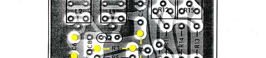
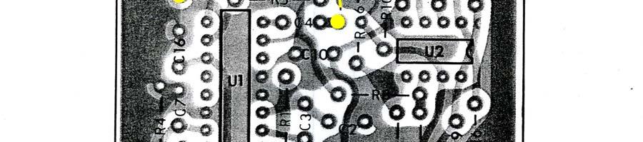
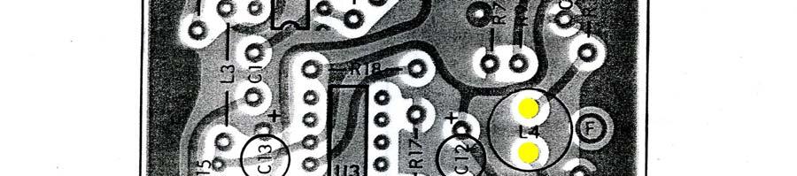
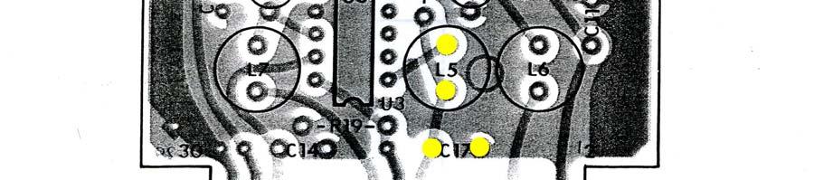
5 FM Demodulator Board showing R2, R3, C6, C17, L4, and L5
WJ-8617B and WJ-8618B HF Upgrades: 500 KHz to 1100 MHz By: Stephen Pappin
 WJ-8617B and WJ-8618B HF Upgrades: 500 KHz to 1100 MHz By: Stephen Pappin The typical frequency coverage for an 8617B or 8618B is from 20 MHz to 1100 MHz (500 MHz without FE). These versions have pre selectors
TS-870: Installing the Inrad Roofing Filter Mod
 TS-870: Installing the Inrad Roofing Filter Mod The TS-870 roofing filter mod consists of a 6 pole, 4 to 5 khz wide filter followed by a high dynamic range feedback amplifier. The amplifier provides enough
SoftRock v5.0 Builder s Notes. December 12, Building a QSD Kit
 SoftRock v5.0 Builder s Notes December 12, 2005 Building a QSD Kit Be sure to use a grounded tip soldering iron in building the QSD board. The soldering iron needs to have a small tip, (0.05-0.1 inch diameter),
! February 9, 1970 GR-78!! Bulletin No: Transistor General Coverage Rcvr!
 ! February 9, 1970 GR-78-1! Rocker Switches [PN 60-45] S.P.S.T. switch is being replaced by [PN 60-48] D.P.D.T. switch with improved contacts. Four of the six lugs are removed when it is used as a S.P.S.T.
IC-765: Installing the Inrad Roofing Filter Mod
 IC-765: Installing the Inrad Roofing Filter Mod The Icom IC-765 roofing filter mod consists of a 6-pole, 4 khz wide filter followed by a high dynamic range, feedback amplifier. The amplifier provides enough
TS-850: Installing the Inrad Roofing Filter Mod
 TS-850: Installing the Inrad Roofing Filter Mod The TS-850 Roofing Filter Mod consists of a 6 pole, 4 to 5 khz wide filter followed by a high dynamic range feedback amplifier. The amplifier provides enough
IC-781: Installing the Inrad Roofing Filter Mod
 IC-781: Installing the Inrad Roofing Filter Mod The Icom IC-781 roofing filter mod consists of a 6-pole, 4 to 5 khz wide filter followed by a high dynamic range, feedback amplifier. The amplifier provides
S-Pixie QRP Kit. Student Manual. Revision V 1-0
 S-Pixie QRP Kit Student Manual Revision V 1-0 Introduction The Pixie 2 is a small, versatile radio transceiver that is very popular with QRP (low power) amateur radio operators the world over. It reflects
INTERNATIONAL RADIO CORP
 I N R A D INTERNATIONAL RADIO CORP 13620 Tyee Road Umpqua, OR 97486 (541) 459-5623 fax (541) 459 5632 E-mail: inrad@rosenet.net www.qth.com/inrad IC-775 ROOFING FILTER INSTALLATION INSTRUCTIONS The IC-775
Assembly Instructions for the 1.5 Watt Amplifier Kit
 Assembly Instructions for the 1.5 Watt Amplifier Kit 1.) All of the small parts are attached to a sheet of paper indicating both their value and id. 2.) Leave the parts affixed to the paper until you are
TS-930: Installing the Inrad Roofing Filter Mod
 TS-930: Installing the Inrad Roofing Filter Mod The TS-930 roofing filter mod consists of a 6 pole, 4 to 5 khz wide filter followed by a high dynamic range, feedback amplifier. The amplifier provides enough
SoftRock v6.0 Builder s Notes. April 6, 2006
 SoftRock v6.0 Builder s Notes April 6, 006 Be sure to use a grounded tip soldering iron in building the v6.0 SoftRock circuit board. The soldering iron needs to have a small tip, (0.05-0. inch diameter),
SoftRock v6.0 Builder s Notes. May 22, 2006
 SoftRock v6.0 Builder s Notes May 22, 2006 Be sure to use a grounded tip soldering iron in building the v6.0 SoftRock circuit board. The soldering iron needs to have a small tip, (0.05-0.1 inch diameter),
TS-950: Installing the Roofing Filter Mod
 TS-950: Installing the Roofing Filter Mod The Kenwood TS-950 Roofing Filter Mod consists of a 6 pole, 4 to 5 khz wide filter followed by a high dynamic range feedback amplifier. The amplifier provides
FREQUENCY AGILE FM MODULATOR INSTRUCTION BOOK IB
 FMT615C FREQUENCY AGILE FM MODULATOR INSTRUCTION BOOK IB1215-02 TABLE OF CONTENTS SECTION SUBJECT 1.0 Introduction 2.0 Installation & Operating Instructions 3.0 Specification 4.0 Functional Description
G6ALU 20W FET PA Construction Information
 G6ALU 20W FET PA Construction Information The requirement This amplifier was designed specifically to complement the Pic-A-Star transceiver developed by Peter Rhodes G3XJP. From the band pass filter an
SPECIFICATIONS: Subcarrier Frequency 5.5MHz adjustable, FM Modulated +/- 50KHz. 2nd 11MHz >40dB down from 5.5MHz
 Mini-kits AUDIO / SUBCARRIER KIT EME75 Version4 SPECIFICATIONS: Subcarrier Frequency 5.5MHz adjustable, FM Modulated +/- 50KHz Subcarrier Output 1.5v p-p Output @ 5.5MHz DESCRIPTION & FEATURES: The Notes
EXPERIMENT #2 CARRIER OSCILLATOR
 EXPERIMENT #2 CARRIER OSCILLATOR INTRODUCTION: The oscillator is usually the first stage of any transmitter. Its job is to create a radio-frequency carrier that can be amplified and modulated before being
ITT Technical Institute. ET275 Electronic Communications Systems I Onsite Course SYLLABUS
 ITT Technical Institute ET275 Electronic Communications Systems I Onsite Course SYLLABUS Credit hours: 4 Contact/Instructional hours: 50 (30 Theory Hours, 20 Lab Hours) Prerequisite(s) and/or Corequisite(s):
ET275P Electronic Communications Systems I [Onsite]
![ET275P Electronic Communications Systems I [Onsite]](/thumbs/85/92760903.jpg "ET275P Electronic Communications Systems I [Onsite]") ET275P Electronic Communications Systems I [Onsite] Course Description: In this course, several methods of signal transmission and reception are covered, including such techniques as mixing, modulating
ET275P Electronic Communications Systems I [Onsite] Course Description: In this course, several methods of signal transmission and reception are covered, including such techniques as mixing, modulating
E-200D ALIGNMENT. See the end of the procedure for the location of the calibration points. EQUIPMENT REQUIRED
 E-200D ALIGNMENT NOTE: This is not an official B&K alignment procedure. This procedure was created by experimenting with an E-200D. However when this procedure is followed, the resulting calibration should
ALX-SSB 5 Band Filter Assembly Manual 19 November 2018
 ALX-SSB 5 Band Filter Assembly Manual 19 November 2018 Contents Theory of Operation:... 1 Figure 1... 2 Parts Included:... 4 Board Overview:... 5 Figure 2... 5 Figure 3... 5 Board Assembly:... 6 Cable
CW-ADD. Universal CW Adapter for SSB Transceivers. Assembly manual. Last updated: October 1,
 CW-ADD Universal CW Adapter for SSB Transceivers Assembly manual Last updated: October 1, 2017 ea3gcy@gmail.com Updates and news at: www.ea3gcy.com Thanks for building the Universal CW Adapter kit CW-ADD
Read This Page First
 Read This Page First If you are reading this you know the manuals are always available at QRPKITS.com. This is version 8.0 of the manual dated 4/27/2016. There is no need to print out the whole assembly
Circuit Board Assembly Instructions
 Circuit Board Assembly Instructions This document walk you through the assembly of the Base4 Clock v1.2 - v1.3 circuit boards. Important note for kit buyers The color and appearance of the components may
DEM Part Number L144-28INTCK 144 MHz Transverter Kit and complete kit
 DEM Part Number L144-28INTCK 144 MHz Transverter Kit and complete kit Power Out: Noise Figure and Gain: DC Power Requirement: 50 mw linear minimum 3.5 db NF nominal, 5 dbg maximum 12-15.5 VDC, 13.8 nominal
ECE 145A/218A, Lab Project #1a: passive Component Test.
 ECE 145A/218A, Lab Project #1a: passive Component Test. September 28, 2017 OVERVIEW... 2 GOALS:... 2 PRECAUTIONS TO AVOID INSTRUMENT DAMAGE... 2 SAFETY PRECAUTIONS... 2 READING:... 3 NETWORK ANALYZER CALIBRATION...
The Uniden Grant XL Owners Site
 The Uniden Grant XL Owners Site Modifications page for the Grant XL (For Informational purposes only) The author of this site takes NO responsibility for illegal modifications and/or use of illegally modified
Modification Details.
 Front end receiver modification for DRM: AKD Target Communications receiver. Model HF3. Summary. The receiver was modified and capable of receiving DRM, but performance was limited by the phase noise from
CA3102. Dual High Frequency Differential Amplifier For Low Power Applications Up to 500MHz. Features. Applications. Ordering Information.
 CA Data Sheet November 999 File Number 6.6 Dual High Frequency Differential Amplifier For Low Power Applications Up to MHz The CA consists of two independent differential amplifiers with associated constant
Ten Tec DDS Board Assembly Procedure
 05 May 2014 Ten Tec DDS Board Assembly Procedure You will find a photo of a completed board at the end of these instructions. Refer it whenever clarification is required. 1. AD9835 Attachment If you purchased
12kHz LIF Converter V2.43 9Mhz version
 12kHz LIF Converter V2.43 9Mhz version Please Note: This document supersedes all previously released documents and drawings on the LIF subject. This is the latest and most up-to-date document at this time.
Treetop Circuits Owner s Manual for SB-SB-600 Adapter Version 1
 The SB-600 SSB adapter from Treetop Circuits (Fig. 1) is designed specifically as an accessory to the Hammarlund SP-600 series of receivers. It provides enhanced performance on SSB and CW signals, using
Assembly Instructions for the FRB FET FM 70 Watt Amp
 Assembly Instructions for the FRB FET FM 70 Watt Amp 1.) Orient the circuit board with the diagram 2.) Use a narrow chisel tip 25-30 watt soldering iron for assembly 3.) All the small parts are taped onto
Stand Alone VXO (SAVXO) Assembly Manual Manual Version 1.0B_
 Assembly Manual Manual Version 1.0B_") Stand Alone VXO (SAVXO) Assembly Manual Manual Version.0B_0-6-0 Designed by: Jim Kortge, K8IQY Kitted & Sold by: 4 State QRP Group Copyright: 0 Forward Thank you for purchasing a 4 State QRP Group Stand
Stand Alone VXO (SAVXO) Assembly Manual Manual Version.0B_0-6-0 Designed by: Jim Kortge, K8IQY Kitted & Sold by: 4 State QRP Group Copyright: 0 Forward Thank you for purchasing a 4 State QRP Group Stand
Building the Toothpick Audio CW Filter
 Building the Toothpick Audio CW Filter Introduction The toothpick is a simple variable bandpass audio filter designed to compliment the Splinter QRPp Trans-Receiver. The filter also contains an audio amplifier
INTEGRATED CIRCUITS DATA SHEET. TBA120U Sound I.F. amplifier/demodulator for TV. Product specification File under Integrated Circuits, IC02
 INTEGRATED CIRCUITS DATA SHEET Sound I.F. amplifier/demodulator for TV File under Integrated Circuits, IC02 March 1986 GENERAL DESCRIPTION The is an i.f. amplifier with a symmetrical FM demodulator and
Building the Sawdust Regenerative Receiver
 Building the Sawdust Regenerative Receiver Introduction The Sawdust is a super regenerative receiver using the basic Armstrong design architecture. The receiver uses one toroidal transformer to provide
MODIFICATION OF SANGEAN ATS909X
 !1 MODIFICATION OF SANGEAN ATS909X The Sangean ATS 909x is a great receiver but has some points to improve. I did the following modifications and I am very satisfied with it. 1) 2) removal of wheel spring
ADDENDUM NUMBER 2 TO MAINTENANCE MANUAL LBI-38673J Refer to ECO#
 ADDENDUM NUMBER 2 TO MAINTENANCE MANUAL Refer to ECO#20043005 GENERAL This addendum documents a change to the RX Front End Module (19D902782G3, G4, & G7) Maintenance Manual. Torque specification changed
Pacific Antenna Easy Transmitter Kit
 Pacific Antenna Easy Transmitter Kit Introduction The Easy Transmitter kit from qrpkits.com provides a crystal controlled transmitter with VXO tuning. The circuit consists of a N3904 based crystal oscillator
LM1868 AM FM Radio System
 LM1868 AM FM Radio System General Description The combination of the LM1868 and an FM tuner will provide all the necessary functions for a 0 5 watt AM FM radio Included in the LM 1868 are the audio power
The Crashcup 1V40 1W Transmitter
 The Crashcup 1V40 1W Transmitter by Chris Trask / N7ZWY Sonoran Radio Research P.O. Box 25240 Tempe, AZ 85285-5240 Email: christrask@earthlink.net 7 January 2009 Trask, Crashcup 1V40 1 7 January 2009 Introduction
D. Gillespie Designs. SCA-35 Capacitor Board. Installation Manual. D. Gillespie Designs with EFB TM
 D. Gillespie Designs SCA-5 Capacitor Board with EFB TM Installation Manual D. Gillespie Designs www.tronola.com Thank you for choosing our SCA-5 Capacitor Board with *EFB. We feel it is the single most
Building the Sawdust Regenerative Receiver
 Building the Sawdust Regenerative Receiver Introduction The Sawdust is a super regenerative receiver using the basic Armstrong design architecture. The receiver uses one toroidal transformer to provide
HAMTRONICS TB901 FM EXCITER INSTALLATION, OPERATION, & MAINTENANCE
 HAMTRONICS TB901 FM EXCITER INSTALLATION, OPERATION, & MAINTENANCE GENERAL INFORMATION. The TB901 is a single-channel low power fm transmitter (exciter) designed to provide 300-600 milliwatts continuous
Easy Transmitter. Support ETX_REV5_Manual V2.7 Revised
 Easy Transmitter Introduction The Easy Transmitter kit from qrpkits.com provides a basic, crystal controlled transmitter with VXO tuning to provide a small tuning range around the crystal frequency. It
TG37 SSB BFO ADAPTER
 TG37 SSB BFO ADAPTER Operation Manual History Rev 1.0: Sep-24-2011 by Tao Qu Rev 1.1: Oct-01-2011 by Tao Qu Table of Contents 01. Before Using 02. Power Supply 03. Power On and Power Off 04. Application
Hendricks QRP Kits BITX20A to BITX17A Conversion Instructions
 Hendricks QRP Kits BITX20A to BITX17A Conversion Instructions 30 November 2008 Converting your BITX20A Kit to a BITX17A Kit is not all that complex. It only requires that you change crystals and some resonance
DATASHEET CA3054. Features. Applications. Ordering Information. Pinout. Dual Independent Differential Amp for Low Power Applications from DC to 120MHz
 DATASHEET CA5 Dual Independent Differential Amp for Low Power Applications from DC to MHz FN88 Rev.. Jan, 7 The CA5 consists of two independent differential amplifiers with associated constant current
DRM Receive Conversion for Yaesu FT920 HF Transceiver by Don M0DKS
 1. Introduction This conversion describes the addition of the DRM receive function for a Yaesu FT920 HF Transceiver that is equipped with the FM-1 optional FM transceive board. The FT920 is a double hetrodyne
EE431 Noise Homework (not to be handed in) Feb. 9, 2013
 Feb. 9, 2013") Feb. 9, 2013 Noise homework problems (temperature is 300 kelvins unless otherwise specified). You are given all the needed information. Check your math or method if you think you need more information.
Feb. 9, 2013 Noise homework problems (temperature is 300 kelvins unless otherwise specified). You are given all the needed information. Check your math or method if you think you need more information.
Beta-test ED1 PCB installed in I0CG s K1
 K1 SSB Modification (Ed.2) This description provides the receiver (RX) modifications, assembly, alignment and operation as a first step. In a second step you can add the remaining transmitter (TX) modifications,
PM24 Installation Instructions
 Marchand Electronics Inc. PO Box 473, Webster, NY 14580 Tel:(716) 872-0980 Fax:(716) 872-1960 info@marchandelec.com http://www.marchandelec.com (c)1997 Marchand Electronics Inc. PM24 Installation Instructions
The Icom PCR-1000 as a SDR RF Front End OscarOnline.org David Carr, KD5QGR partially based on a document by Edgar J. Kaiser, DF2MZ
 The Icom PCR-1000 as a SDR RF Front End OscarOnline.org David Carr, KD5QGR partially based on a document by Edgar J. Kaiser, DF2MZ Purpose: Many times when working in software defined radio some means
Tuna Tunah. Switched Inductor Antenna Tuner. Builder's Guide by Kevin Gilot NZ1I & Rex Harper W1REX. version 1.2
 Tuna Tunah Switched Inductor Antenna Tuner Builder's Guide by Kevin Gilot NZ1I & Rex Harper W1REX version 1.2 Tuna Tunah List of Materials Qty Description PCB Location ( ) 1-.22uH Inductor (Red-Red-Silver).22
MAINTENANCE MANUAL MDX POWER AMPLIFIER BOARDS 19D904792G2 ( MHz) 19D904792G1 ( MHz) 19D904792G3 ( MHz)
 19D904792G1 ( MHz) 19D904792G3 ( MHz)") MAINTENANCE MANUAL MDX POWER AMPLIFIER BOARDS 19D904792G2 (403-440 MHz) 19D904792G1 (440-470 MHz) 19D904792G3 (470-512 MHz) TABLE OF CONTENTS Page DESCRIPTION... 1 CIRCUIT ANALYSIS... 1 SERVICE NOTES...
MAINTENANCE MANUAL MDX POWER AMPLIFIER BOARDS 19D904792G2 (403-440 MHz) 19D904792G1 (440-470 MHz) 19D904792G3 (470-512 MHz) TABLE OF CONTENTS Page DESCRIPTION... 1 CIRCUIT ANALYSIS... 1 SERVICE NOTES...
ECE 201 LAB 8 TRANSFORMERS & SINUSOIDAL STEADY STATE ANALYSIS
 Version 1.1 1 of 8 ECE 201 LAB 8 TRANSFORMERS & SINUSOIDAL STEADY STATE ANALYSIS BEFORE YOU BEGIN PREREQUISITE LABS Introduction to MATLAB Introduction to Lab Equipment Introduction to Oscilloscope Capacitors,
FMR611S SUBCARRIER DEMODULATOR
 ALL ENGINEERING DESIGNS, DRAWINGS AND DATA CONTAINED HEREIN ARE PROPRIETARY AND MAY NOT BE REPRODUCED, COPIED OR OTHERWISE USED WITHOUT WRITTEN AUTHORIZATION FMR611S SUBCARRIER DEMODULATOR INSTRUCTION
Homework Assignment 03
 Question (75 points) Homework Assignment 03 Overview Tuned Radio Frequency (TRF) receivers are some of the simplest type of radio receivers. They consist of a parallel RLC bandpass filter with bandwidth
K-PO SSB 2100 SSB BFO ADAPTER
 K-PO SSB 2100 SSB BFO ADAPTER Operation Manual Table of Contents 01. Before Using 02. Power Supply 03. Power On and Power Off 04. Application On WR2100 05. Application On S450DLX 06. About Battery 07.
 LNF1-A Amplifier Modifications Dated March 17, 2009 These amplifiers were manufactured in the late 1970s by Electronics One, Inc., Atlanta, Georgia. Electronics One was a firm which manufactured products
PXD30-xxWS-xx-Single Output DC/DC Converters
 PXD30-xxWS-xx-Single Output DC/DC Converters 9 to 36 Vdc and 18 to 75 Vdc input, 1.5 to 15 Vdc Single Output, 30W Applications Wireless Network Telecom / Datacom Industry Control System Measurement Semiconductor
Application Note. Soldering Guidelines for Surface Mount Filters. 1. Introduction. 2. General
 Soldering Guidelines for Surface Mount Filters 1. Introduction This Application Guideline is intended to provide general recommendations for handling, mounting and soldering of Surface Mount Filters. These
10W HF Linear PA. A low-cost, high-performance HF Linear PA covering 2-30MHz. 10W HF Linear Power Amplifier kit assembly manual
 10W HF Linear PA 10W HF Linear Power Amplifier kit assembly manual A low-cost, high-performance HF Linear PA covering 2-30MHz Designed and produced by QRP Labs, 2018 10W HF Linear PA kit assembly 1.01
Manual Version July 2007
 Manual Version 1.2 - July 2007 Page 1 Table of Contents Section1: M3 Phono Board Build...3 Phono Board Parts List...3 Preparation...4 Fitting the Valve Bases...6 Installing the Resistors...7 Starting the
JC-5 4KW PEP, 1KW RMS AUTO ANTENNA COUPLER
 JC-5 4KW PEP, 1KW RMS AUTO ANTENNA COUPLER 1) DIRECTLY CONTROLLED BY ICOM, ALINCO & KENWOOD. 2) INDEPENDENT CAPACITOR INPUT AND OUTPUT BLOCKS! 3) 3 mm COIL WIRE & INTERNAL FAN FOR THE BIG COILS! 4) DIPPED
WA3RNC 30 METER CRYSTALPLEXER TRANSMITTER KIT ASSEMBLY INSTRUCTIONS
 WA3RNC 30 METER CRYSTALPLEXER TRANSMITTER KIT ASSEMBLY INSTRUCTIONS Description The WA3RNC 30 Meter Crystalplexer is a low power crystal controlled QRP transmitter offering a significantly improved tuning
Pacific Antenna 10 Watt HF Amplifier Kit
 Pacific Antenna 0 Watt HF Amplifier Kit Description Our 0 watt Linear, HF amplifier kit is designed to increase the power output of low power transmitters. Gives up to 5dB gain and includes an input attenuator
RadiØKit Μ CW HAM RADIO TRANSCEIVER KIT. Assembly and operating manual
 RadiØKit-120 20Μ CW HAM RADIO TRANSCEIVER KIT Assembly and operating manual Boreiou Ipirou 78 Kolonos Athens- Greece - 10444 Tel: 210.5150527 210.5132673 www.freebytes.com Thank you for buying RadiØKit-1,
QRPGuys Michigan Mighty Might Plus 40M Transmitter
 QRPGuys Michigan Mighty Might Plus 40M Transmitter First, familiarize yourself with the parts and check for all the components. If a part is missing, please contact us and we will send one. You must use
INTEGRATED CIRCUITS DATA SHEET. TEA5591A AM/FM radio receiver circuit. Product specification File under Integrated Circuits, IC01
 INTEGRATED CIRCUITS DATA SHEET File under Integrated Circuits, IC01 February 1990 GENERAL DESCRIPTION The is a 24-pin integrated radio circuit, derived from the TEA5591 and is designed for use in AM/FM
Ref: UAN/DIN/SCNS rev.: -- Date February 17, VHF DATA Radio EVR A EVR A EVR B
 VHF DATA Radio EVR750-04- EVR750-04-0200A EVR750-04-0100B Similarity analysis with already qualified P/N EVR750-03- and configuration status p.1/11 CONTENT 1. Introduction...3 2. Composition of the Part-Number...3
PreLab 7: LED Blinker (Due Oct 30)
") GOAL PreLab 7: LED Blinker (Due Oct 30) The overall goal of Lab 7 is to demonstrate a two-led blinker with adjustable frequency. This is a two-week lab. The first week involves designing and testing a
GOAL PreLab 7: LED Blinker (Due Oct 30) The overall goal of Lab 7 is to demonstrate a two-led blinker with adjustable frequency. This is a two-week lab. The first week involves designing and testing a
Homework Assignment 01
 Homework Assignment 01 In this homework set students review some basic circuit analysis techniques, as well as review how to analyze ideal op-amp circuits. Numerical answers must be supplied using engineering
Exercise 2: Q and Bandwidth of a Series RLC Circuit
 Series Resonance AC 2 Fundamentals Exercise 2: Q and Bandwidth of a Series RLC Circuit EXERCISE OBJECTIVE When you have completed this exercise, you will be able to calculate the bandwidth and Q of a series
HAMTRONICS LPA 2-25R REPEATER POWER AMPLIFIER: ASSEMBLY, INSTALLATION, & MAINTENANCE
 HAMTRONICS LPA 2-25R REPEATER POWER AMPLIFIER: ASSEMBLY, INSTALLATION, & MAINTENANCE GENERAL INFORMATION. The Power Amplifier is a class C device designed to be installed as an integral part of a transmitter
ERICSSONZ LBI-39123A. MAINTENANCE MANUAL FOR 21.4 MHz RECEIVER IF MODULE 12.5/25 khz CHANNEL SPACING 19D902783G7 DESCRIPTION TABLE OF CONTENTS
 A MAINTENANCE MANUAL FOR 21.4 MHz 12.5/25 khz CHANNEL SPACING 19D902783G7 TABLE OF CONTENTS Page DESCRIPTION............................................ Front Cover GENERAL SPECIFICATIONS....................................
QLG1 GPS Receiver kit
 QLG1 GPS Receiver kit 1. Introduction Thank you for purchasing the QRP Labs QLG1 GPS Receiver kit. This kit will provide a highly sensitive, highly accurate GPS receiver module, using the popular MediaTek
UNIVERSITY OF NORTH CAROLINA AT CHARLOTTE Department of Electrical and Computer Engineering
 UNIVERSITY OF NORTH CAROLINA AT CHARLOTTE Department of Electrical and Computer Engineering EXPERIMENT 2 BASIC CIRCUIT ELEMENTS OBJECTIVES The purpose of this experiment is to familiarize the student with
Building a Bitx20 Version 3
 Building a Bitx20 Version 3 The board can be broken into sections and then built and tested one section at a time. This will make troubleshooting easier as any problems will be confined to one small section.
LBI-38673F MAINTENANCE MANUAL FOR RECEIVER FRONT END MODULE 19D902782G3, G4, & G7 DESCRIPTION TABLE OF CONTENTS
 MAINTENANCE MANUAL FOR 19D902782G3, G4, & G7 TABLE OF CONTENTS Page DESCRIPTION........................................... Front Cover SPECIFICATIONS......................................... 1 CIRCUIT
Hear SSB amateurs on your shortwave receiver
 Hear SSB amateurs on your shortwave receiver Peter Parker VK3YE Since most amateurs switched from AM to single sideband more than 40 years ago, it hasn't been possible to receive them with an unaided shortwave
HF Receivers, Part 2
 HF Receivers, Part 2 Superhet building blocks: AM, SSB/CW, FM receivers Adam Farson VA7OJ View an excellent tutorial on receivers NSARC HF Operators HF Receivers 2 1 The RF Amplifier (Preamp)! Typical
SEA INC OF DELAWARE PRELIMINARY MAINTENANCE MANUAL EXCERPTS CONCERNING TUNEUP MF/HF SSB GMDSS RADIOTELEPHONE/DSC CONTROLLER MODEL SEA 245
 SEA INC OF DELAWARE PRELIMINARY MAINTENANCE MANUAL EXCERPTS CONCERNING TUNEUP MF/HF SSB GMDSS RADIOTELEPHONE/DSC CONTROLLER MODEL SEA 245 (c) Copyright 2001 SEA, Inc. All rights reserved. SEA, Inc. 7030
Classic Valve Design
 DynaMull Driver Board for the Dynaco ST-70 Classic Valve Design Classic Valve Design assumes no responsibility for circuit or user damage from the use or misuse of these boards or any other product. We
V6.2 SoftRock Lite Builder s Notes. November 17, 2006
 V6.2 SoftRock Lite Builder s Notes November 17, 2006 Be sure to use a grounded tip soldering iron in building the v6.2 SoftRock circuit board. The soldering iron needs to have a small tip, (0.05-0.1 inch
10 GHz Microwave Link
 10 GHz Microwave Link Project Project Objectives System System Functionality Testing Testing Procedures Cautions and Warnings Problems Encountered Recommendations Conclusion PROJECT OBJECTIVES Implement
HF Amateur SSB Receiver
 HF Amateur SSB Receiver PCB Set for radio club project http://rhelectronics.net PCB for DIY HF Amateur SSB Receiver 20M The receiver is a simple syperheterodyne type with quartz crystal filter. The circuit
Microphone audio, from the MFJ-1278B to your transmitter. Ground, audio and PTT common. Push-to-talk, to allow the MFJ-1278B to key your transmitter.
 Computer interfacing, covered in the previous chapter, is only half the interfacing task. The other half is connecting your MFJ-1278B to your radios. MFJ-1278B Radio Ports Interfacing the MFJ-1278B to
G1MFG.com. Home of the cheapest ATV transmitters and receivers in Europe! Please read all of this document before attempting to use your controller.
 G1MFG.com Home of the cheapest ATV transmitters and receivers in Europe! 23/24cm LCD controller technical information V3 software Please read all of this document before attempting to use your controller.
S&T GeoTronics LLC Open DSKY with AGC Assembly Instructions
 S&T GeoTronics LLC Open DSKY with AGC Assembly Instructions First, make sure you have all the required components: HARDWARE Qty Item 1 DSKY PCB v1.0d 1 Arduino Nano 1 VA RTC 1 IMU 1 Buck StepDown 1 SKM53
Build Notes Si570 Controller II - by Pete Juliano N6QW,
 Build Notes Si570 Controller II - by Pete Juliano N6QW, radioguy90@hotmail.com (As of June 10, 2012) I bought just the board and programmed Micro Controller Unit from K5BCQ. Therefore I had to purchase
ECE453 Lab 5: FM Quadrature Demodulation / PCB Design Using Eagle
 ECE453 Lab 5: FM Quadrature Demodulation / PCB Design Using Eagle In this lab, you will work with your partner to design a printed circuit board for a quadrature demodulator IC and supporting components.
Ten-Tec Orion/Orion II Users Manual Addendum Firmware Version V3
 Ten-Tec Orion/Orion II Users Manual Addendum Firmware Version V3 It is very important that you read this document in its entirety before using the V3 firmware. Some features behave differently than they
DRTXM2 TRANSMITTER BILL OF MATERIAL IDENT QTY PART NUMBER DESCRIPTION
 DRTXM2 TRANSMITTER BILL OF MATERIAL H1 C1-5,7,10-11,15,17-18,20, 22-28,34,38, 43-46,49-53,1A,2A 8 Right Angle LED Mount 0 0.01uf 50V Ceramic Disc Capacitor 31 0.1 UF/50V Decoupling Capacitors C13,14,39-42
SSRP LTC1746 Assembly Manual V0.1 Check the most recent version
 SSRP LTC1746 Assembly Manual V0.1 Check the most recent version http://oscar.dcarr.org/ssrp/hardware/ltc1746/ltc1746.php Introduction This manual details the general assembly process for the SSRP LTC1746
The ROSE 80 CW Transceiver (Part 1 of 3)
") Build a 5 watt, 80 meter QRP CW Transceiver!!! Page 1 of 10 The ROSE 80 CW Transceiver (Part 1 of 3) Build a 5 watt, 80 meter QRP CW Transceiver!!! (Designed by N1HFX) A great deal of interest has been
Build a 5 watt, 80 meter QRP CW Transceiver!!! Page 1 of 10 The ROSE 80 CW Transceiver (Part 1 of 3) Build a 5 watt, 80 meter QRP CW Transceiver!!! (Designed by N1HFX) A great deal of interest has been
PS2-SMC-06 Servo Motor Controller Interface
 PS2-SMC-06 Servo Motor Controller Interface PS2-SMC-06 Full Board Version PS2 (Playstation 2 Controller/ Dual Shock 2) Servo Motor Controller handles 6 servos. Connect 1 to 6 Servos to Servo Ports and
Penrose Quantizer Assembly Guide
 Penrose Quantizer Assembly Guide Schematic and BOM The schematic can be found here: www.sonic-potions.com/public/penrosequantizerschematic.pdf The BOM is available at google docs: Link to BOM Prepare the