CD42-STS Subsea Diver/ROV Pig Location and Tracking System
|
|
|
- Sharleen Collins
- 5 years ago
- Views:
Transcription
 258-6068 worldwide www.pigging.com support@pigging.")
1 CD42-STS Subsea Diver/ROV Pig Location and Tracking System USER GUIDE 24-HOUR EMERGENCY TELEPHONE NUMBER +1(918) North Juniper Avenue Broken Arrow, Oklahoma U.S.A. +1 (918) worldwide
2 Information in this document is subject to change without notice and applies only to the version of software, hardware or firmware described on the title page. The hardware and firmware described in this document are designed, manufactured and written by CDI. The hardware and firmware copyright CDI with all rights reserved. This document CDI. All rights reserved. Document Number Manual Revision 03 Mar 2016 The CD42-STS is covered under United States Patent. WARNING Any operation involving work on pipelines containing gases or liquids under pressure is potentially hazardous. It is necessary, therefore, to follow correct procedures in the use of this equipment to maintain a safe working environment. No person should use this equipment unless fully aware of potential hazards of working with pressurized pipelines and trained in the procedures stated in this manual. The purchaser of this equipment is responsible for the training and competence of operators and the manner in which it is used. Contact CDI immediately should any difficulty arise in the use of this equipment. WARNING Always use caution when opening any CDI transmitter that has been in a pressurized environment. It is possible for pressurized liquid or gas to leak into a transmitter and remain there even after the transmitter has been removed from the pipeline. Always point the transmitter away from yourself or others when opening a cover or end cap. Page 2 of 36
3 CONTENTS INTRODUCTION...4 DEPLOYMENT...4 COMPONENTS...4 POWER...5 DETECTION METHODS...5 GETTING STARTED...6 Physical Checkout...6 Power ON...7 Operational Checkout...8 OPERATION...11 Tracking...11 Locating...14 Pinpointing...15 CHANGING/INSTALLING BATTERIES...18 OPTIONAL EQUIPMENT...24 ROV Handles...24 Close Proximity Antenna (CPA)...26 WARRANTY, CARE, & MAINTENANCE...32 Warranty...32 Making a Warranty Claim...32 Care and Maintenance...33 Service and Repairs...33 SYSTEM SPECIFICATIONS...34 NOTES...35 ABOUT CDI...36 Page 3 of 36


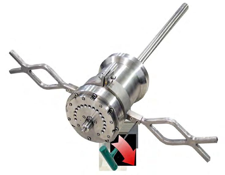
![DEPLOYMENT The CD42-STS may be deployed below the ocean to depths of 8,0000 ft [2,439 m] and is](/docs-images/84/91197659/images/4-2.jpg "designed to be either carried by a diver or ROV.")
![It is rated for a maximum pressure of 3,650 psi [245 bar].](/docs-images/84/91197659/images/4-3.jpg "DIVER HANDLE(S) MINIMUM GAIN SIGNAL GAIN CONTROL BUTTON MAXIMUM GAIN COMPONENTS The CD42-STS is")

4 INTRODUCTION The CD42-STS is a pipeline pig locating and tracking receiver that detects pulsing signals emitted by electromagnetic transmitters in a subsea pipeline. The transmitter signal strength is displayed on an LED array which can be easily seen by a diver or ROV operator who is tracking moving pigs and/or locating a stationary or stuck pig. DEPLOYMENT The CD42-STS may be deployed below the ocean to depths of 8,0000 ft [2,439 m] and is designed to be either carried by a diver or ROV. It is rated for a maximum pressure of 3,650 psi [245 bar]. DIVER HANDLE(S) MINIMUM GAIN SIGNAL GAIN CONTROL BUTTON MAXIMUM GAIN COMPONENTS The CD42-STS is constructed of stainless steel. A control button adjusts antenna gain, which is displayed on an array of 16 light-emitting diodes (LED). The LEDS also indicate transmitter proximity when tracking or locating a pig. Diver handles may be removed and replaced with optional fishtail ROV handles (see pg. 24). Page 4 of 36


 on a change of DETECTION METHODS The CD42-STS can track")
5 ANTENNA The 26.4-in. [670.5 mm] antenna may be removed and replaced with an optional Close Proximity Antenna (CPA). The CPA is sensitive only to very near signals and designed for use where multiple pigs are extremely close to one another such as in launchers and receivers. POWER The CD42-STS is powered by six (6) D-cell alkaline batteries. The batteries are located in the unit s stainless steel housing. Changing these batteries requires disassembly of the housing (see pg. 18). The CD42-STS will operate for up to 60 hours (2.5 days) on a change of batteries. DETECTION METHODS The CD42-STS can track and locate any pig or inline inspection (ILI) tool equipped with a 22 Hz electromagnetic transmitter. Shown here are some of the 22 Hz transmitters manufactured by CDI. Page 5 of 36


6 GETTING STARTED Physical Checkout The CD42-STS receiver is assembled at CDI and should be ready for operation upon receipt. The batteries are installed and the unit is sealed and tested for functionality just prior to shipment. Check for any damage to the CD42-STS receiver after removal from the shipping container. Check the antenna for any bends, dents, or deformities. Page 6 of 36


.")
7 Power ON Remove the large hexagonal plug located on the antenna side of the system to access the power switch. (You ll need a 1 5/8-in. open-end wrench or adjustable wrench to loosen plug). Press the red pushbutton switch to toggle the system power ON/OFF. Inspect O-ring and O-ring groove before replacing plug (see pg. 21 for O-Ring inspection and maintenance information). Replace plug. Tighten until snug (do not over-tighten). Page 7 of 36

8 Operational Checkout When the unit is first powered on, the unit will perform a self-check. This is indicated by a rapid back and forth scrolling of the LED array. The LEDs on each side will flash in succession from bottom to top and back down five times as shown here. The CD42-STS is operational when the self-check has completed, but you may wish to adjust the signal gain before placing the unit into service. (See following pages.) Page 8 of 36


9 Signal Gain When the self-check is complete, the display will indicate the last signal gain (sensitivity) setting stored in the memory by flashing three times and then remain on for another three seconds. Here, the unit has been set to a relatively low gain level of 3. The gain readout will remain on for 3 seconds then the display will go dark. The CD42-STS receiver is now in the operational mode and is looking for electromagnetic pulses. To verify that the unit is operating prior to deployment, bump the antenna with your hand. The displays LEDs will jump and confirm it is operating. Gain Adjustment Press and hold the control button momentarily to redisplay the current gain setting. To increase signal gain, continue to hold the button down. After approximately 3 seconds, you will see the LEDs light in succession from left to right as the gain level increases. Each increment will be set in 1.25-second intervals. After the gain control reaches the full-scale position it will cycle to the zero gain position. Keeping the button pressed will restart the gain increase cycle. Page 9 of 36
 are useful when the CD42-STS is used in very close proximity to a transmitter such as at a pig")

10 Gain Adjustment (cont.) No LEDs lit indicate zero gain position. Low gain settings (1,2, and 3) are useful when the CD42-STS is used in very close proximity to a transmitter such as at a pig launcher or receiver. ZERO GAIN GAIN LEVEL 3 GAIN LEVEL 8 MAXIMUM GAIN The gain setting is stored in non-volatile memory. It is retained when the receiver is powered down and even if batteries are removed. When the unit is powered back up your gain setting will be displayed in the power ON sequence. Page 10 of 36
11 OPERATION: TRACKING/LOCATING LED Array The operator readout for tracking and locating is the 16-LED display. It is read from left to right (minimum to maximum). The LED behavior simulates the movement of the needle on an analog meter. The display contains a peak hold indication whereby an LED will light to indicate the maximum averaged signal received by the CD42-STS receiver. As the signal level increases (or the transmitter gets closer) the peak LED will light and shift to the right and as the signal diminishes the peak LED will shift to the left. The LED indicators that are below the peak LED will pulse to indicate the pulses received by the transmitter. Tracking a Moving Pig The CD42-STS system must be within a few meters of a pipeline, with the antenna held parallel to the pipeline. Typically, the diver or ROV operator will set up with the antenna parallel to the pipeline in a location where he knows the pig will pass and wait. Page 11 of 36


12 NOTE: When the CD42-STS receiver is used in conjunction with an ROV, the thruster motors will create large magnetic fields that will interfere with the operation of the CD42-STS receiver. It may be necessary to park the ROV periodically to create a quiet electromagnetic environment for this system. This is an unavoidable side-effect of all magnetic-based pig location and tracking systems. Electromagnetic fields are three-dimensional. A 3-dimensional rendering of a typical Signal field might resemble this. (Note STS antenna orientation parallel to pipe.) Page 12 of 36


13 As the pig approaches the unit, the measured signal strength increases. This is a two-dimensional representation of a signal peak: SIGNAL PEAK COIL CENTERLINE The peak LED will shift to the right to indicate the increasing average strength as transmitter pulse strength increases. After the pig passage, the operator moves quickly to the next predetermined spot to wait and monitor the signal for the approach of the pig. Page 13 of 36

14 TRACKING/LOCATING (cont.) Locating a Stationary Pig Locating a stuck pig in a pipeline is one of the most useful features of the CD42-STS. The best way to minimize the amount of searching for a stuck pig is to properly track the pig in the pipeline so that when and if it does become stuck, the amount of pipeline in which it could be is at a minimum. If the last confirmed tracking location is known, all the operator has to do to locate a stuck pig is back-track the pipeline until the receiver reads the signal. To locate a stationary pig, the diver or ROV operator moves along the pipeline with the antenna held parallel to the pipeline. The peak signal indicator will shift right as the operator approaches the stuck pig. If the peak signal starts to diminish in strength (peaks start falling toward the left) the operator has passed the stuck pig. Page 14 of 36
15 Back-track again until the perceived maximum signal is received. At this point the CD42-STS receiver is at its closest approach to the pig. This point on the pipeline can be marked for cutting or other remedial actions. (See next section, Pinpointing.) SIGNAL PEAK COIL CENTERLINE Page 15 of 36

 signal rather than the maximum.")
16 Pinpointing a Stationary Pig Once the approximate location of a stationary pig is known, a more precise method known as pinpointing can be used to further increase the location accuracy. With the pinpointing method, the antenna of the CD42-STS is rotated to be perpendicular to the pipeline rather than parallel. Once rotated, the operator looks for the minimum ( null ) signal rather than the maximum. A 3-D representation of the signal null is shown here: Page 16 of 36


17 This method relies upon the physics of the coupling between the magnetic transmitter inside the pipeline and the receiving antenna on the outside of the pipeline. SIGNAL NULL COIL CENTERLINE Page 17 of 36

 socket head cap screws (1/4 20 x 5/8 in.) and lock washers from the operator end of the housing.")
18 CHANGING/INSTALLING BATTERIES The CD42-STS is shipped with 1.5 VDC D-cell alkaline batteries installed. The estimated battery life is approximately 60 hours (2.5 days). WARNING Do not perform this procedure in a hazardous environment. Ensure that you are in a safe and non-explosive atmosphere prior to opening. Always use caution when opening any device that has been in a high-pressure environment such as a deep-sea operation Always position the unit away from yourself or others when opening a cover or end cap. To change batteries: Tool required: 3/16-in Allen wrench Remove the eight (8) socket head cap screws (1/4 20 x 5/8 in.) and lock washers from the operator end of the housing. Note the clocking orientation of the end cap to the antenna positioning. Page 18 of 36


19 CAUTION: The end plate is heavier than it looks; be careful not to damage the O-ring or circuitry under the plate. Do not bump or drop the end plate. Avoid straining the ribbon cable or cable connections. Carefully disconnect ribbon cable connector from circuit board on end plate. Page 19 of 36
 end facing out.")


20 Remove batteries. Note battery polarity. The four upper batteries are installed Positive (+) end facing out. WARNING When installing batteries, replace all batteries at the same time. When replacing batteries, use batteries from the same package or manufacturing batch whenever possible. This device is designed for use with alkaline batteries. Do not mix alkaline and lithium batteries. Always observe correct polarity when installing batteries. The two lower batteries are installed Positive (+) side inward. Page 20 of 36


")

21 Before replacing end plate, remove and inspect O-ring and O-ring groove for dents deformities ruptures nicks scratches dirt foreign objects or anything else that might interfere with a proper seal. A brittle and/or deformed O-ring may not properly seal. If in doubt, replace it.* Lubricate O-ring with a light coating of high-temperature grease (such as Dow Corning MOLYKOTE 44) * End plate O-ring: CDI Part No Carefully reattach cable connector to end plate circuit board. Ensure both rows of pins are seated properly and that none are bent or broken. Page 21 of 36

 socket head cap screws (1/4 20 x 5/8) and")
22 Ensure plate is lined up properly before installing fasteners. Note the clocking orientation of the end cap to the antenna positioning. Reinsert the eight (8) socket head cap screws (1/4 20 x 5/8) and lock washers. See tightening sequence on next page. Page 22 of 36

 in 20")


23 Tighten the cap screws by hand until snug. Tighten each screw in a rotating cross pattern (shown below) in 20 inchpound increments. (If using a powered driver, avoid over-tightening) Continue until the cap screws reach 60-inch pounds torque. After reaching the 60-inch pound level continue the torque pattern and torque to 70-inch pounds. This is the final torque level. Page 23 of 36


24 OPTIONAL EQUIPMENT ROV Handles These easily-installed fishtail handles are designed for efficient ROV tooling (CDI Part # ). Installation Tool required: 1/8-in. Allen wrench 1. Remove flat socket head screws (two on each side). Page 24 of 36


25 2. Remove stock handles. 3. Insert ROV handles. 4. Secure but do not over-tighten. Page 25 of 36
 Close Proximity Antenna (CPA) The Close Proximity Antenna")


26 OPTIONAL EQUIPMENT (CONT.) Close Proximity Antenna (CPA) The Close Proximity Antenna (CPA)* is sensitive only to nearby signals. Where multiple pigs are in close proximity to one another, the CPA is useful to distinguish an individual PIG without cross-interference from adjacent pigs. *CDI Part # Installation Tool required: 3/16-in. Allen wrench 1. Remove the six (6) socket head cap screws (1/4 20 x 5/8) and lock washers from the standard 26.4-in. [670.5 mm] antenna mounting. Page 26 of 36


27 2. CAREFULLY retrieve the antenna wiring from the unit until you find the connector. Page 27 of 36


28 3. Disconnect standard antenna. Inspect O-ring* and O-ring groove before installing or replacing antenna unit. (See pg. 21 for O-Ring inspection and maintenance information.) *CDI Part No Page 28 of 36


29 4. Connect the CPA and thread the excess wiring back into the unit. 5. Line up CPA with unit as shown. Note orientation of cutout to Power Switch cap (if antenna is improperly installed, it will be difficult to remove cap to power up the unit. Page 29 of 36
 and lock washers.")

30 6. Reinsert the six (6) socket head cap screws (1/4 20 x 5/8 in.) and lock washers. See tightening sequence on next page. Tighten the cap screws by hand until snug. Page 30 of 36
.")

31 Tighten each screw with Allen wrench in a rotating cross pattern (shown below) in 20 inch-pound increments. (If using a powered driver, avoid over-tightening) Continue until the cap screws reach 60-inch pounds torque. After reaching the 60-inch pound level continue the torque pattern and torque to 70-inch pounds. This is the final torque level. The CPA configuration is complete. Page 31 of 36
32 Warranty All equipment sold by Control Devices, Incorporated (CDI) is warranted for a period of one (1) year from the date of shipment to Purchaser, providing the instrument or equipment has not been modified, abused, or used for purposes which it was not designed for. Batteries, probes, leads, magnets, and other consumables subject to wear are not covered by this warranty. CDI will repair or replace faulty equipment during the warranty period when the cause is a defect arising from faulty design, materials or workmanship. Making a Warranty Claim Equipment being considered for warranty repair, or a representative sample thereof, must be returned to CDI at the Purchaser s expense. The equipment must be accompanied by the Purchaser s written order* describing the defect(s) and authorizing CDI to invoice the Purchaser for any charges not covered by the warranty. Upon receipt of the equipment and Purchase Order, CDI will examine the equipment and make a determination of the nature and cause of the defect. If the defect is not covered by the warranty, CDI will quote to Purchaser the cost for replacement or repair equipment, and will not proceed until Purchaser delivers a written acceptance of the quotation. During the one year warranty, CDI will bear the cost to return units repaired under the warranty back to the Purchaser s domestic premises. CDI will return units to foreign countries at Purchaser s expense. * Contact CDI at , ext 143 for CDI RMA Form FM Page 32 of 36
33 Care and Maintenance Equipment designed by CDI is protected against the environment in which it is intended to operate. Much of the equipment is designed for prolonged use in the field without any special maintenance other than routine battery replacements. It is the Purchaser s responsibility to insure that proper precautions are taken during installation and operation so that weather seals are in place, routine maintenance occurs, etc. Failure to perform these operations nullifies this warranty. CDI equipment should only be operated by qualified personnel who are familiar with any and all manuals and procedures for said equipment s operation. Service and Repairs Cost for repairs not covered by the warranty or carried out after the warranty period has expired will be charged at the current hourly or set service rate, plus the cost of materials, upon approval by Purchaser. Equipment for repair must be sent at the Purchaser s expense and be accompanied by the Purchaser s written order describing the defect and authorizing CDI to invoice the Purchaser for labor, materials and return delivery cost. No service or repair will be undertaken until an approved written order is received from the Purchaser. Operating equipment while in a damaged condition nullifies this warranty. Page 33 of 36
34 SYSTEM SPECIFICATIONS Detection Type: Non-Intrusive Electromagnetic Applications: Tracking and/or Locating via Diver or ROV Deployment: Subsea (ROV or Diver) Sensor: Wire-wound Antenna Detection Direction: Bi-Directional Devices Detected: Electromagnetic Transmitters (Standard CD42 Family) Detection Speed: 0.01 meter/sec to 20 meter/sec Visual Indicator: 16 Super-bright LED array indicates transmitter signal strength Power Source: D-Cell (6) Alkaline Batteries Battery Life: 60 hours (2.5 days) Controls: Gain Adjustment via Non-penetrating Pushbutton Dimensions: 36.5 in. [927.1 mm] length x 6 in. [152.4 mm] diameter Operational Temperature Range: 4 F to +140 F [ 20 C to +60 C] Water Depth, Maximum: 8,000 ft [2,438.4 m] Operating Pressure, Maximum: 3,560 psi [245 bar] Housing: 316 Stainless Steel Page 34 of 36
35 NOTES Page 35 of 36


36 ABOUT CDI CDI is a family-owned and operated business located in Broken Arrow, Oklahoma, just 12 miles from downtown Tulsa. Incorporated in 1982, CDI has proudly been manufacturing products in the United States for more than 32 years. CDI currently employs 45 people in the areas of electronics and mechanical design, software and firmware programming, electronics manufacture, machining, and more. All CDI products are designed and built completely in-house utilizing an on-premises machine shop boasting six fullyautomated CNC machines as well as full-time electronics assembly personnel.
CD42-STS Operating Manual Diver/ROV Pipeline Pig Location & Tracking System
 CD42-STS Operating Manual Diver/ROV Pipeline Pig Location & Tracking System March 8, 2011 1801 North Juniper Avenue Broken Arrow, Oklahoma 74012 USA 1 (800) 580-4234 USA & Canada Toll free 1 (918) 258-6068
USER GUIDE. ROV Tracking Receiver North Juniper Avenue Broken Arrow, Oklahoma U.S.A. +1 (918) worldwide
 worldwide") ROV Tracking Receiver USER GUIDE 1801 North Juniper Avenue Broken Arrow, Oklahoma 74012 U.S.A. +1 (918) 258 6068 worldwide www.pigging.com support@pigging.com Information in this document is subject to
ROV Tracking Receiver USER GUIDE 1801 North Juniper Avenue Broken Arrow, Oklahoma 74012 U.S.A. +1 (918) 258 6068 worldwide www.pigging.com support@pigging.com Information in this document is subject to
TRAXALL USER GUIDE. MULTIFREQUENCY PIPELINE PIG TRACKING TRANSMITTERS Models X200/X200T-2AA and X200-3AA
 TRAXALL MULTIFREQUENCY PIPELINE PIG TRACKING TRANSMITTERS Models X200/X200T-2AA and X200-3AA USER GUIDE 1801 North Juniper Avenue Broken Arrow, Oklahoma 74012 U.S.A. +1 (918) 258-6068 worldwide www.pigging.com
TRAXALL USER GUIDE. MULTIFREQUENCY PIPELINE PIG TRACKING TRANSMITTERS Models X300-2C, X300-3C, X300-4C, and X300-5C
 TRAXALL MULTIFREQUENCY PIPELINE PIG TRACKING TRANSMITTERS Models X300-2C, X300-3C, X300-4C, and X300-5C USER GUIDE 1801 North Juniper Avenue Broken Arrow, Oklahoma 74012 U.S.A. +1 (918) 258-6068 worldwide
TRAXALL USER GUIDE North Juniper Avenue Broken Arrow, Oklahoma U.S.A. +1 (918) worldwide.
 worldwide.") TRAXALL MULTIFREQUENCY PIPELINE PIG TRACKING TRANSMITTERS Models X300-2C-Ex, X300-3C-Ex, X300-4C-Ex, and X300-5C-Ex (ATEX-IECEx Certification) USER GUIDE 1801 North Juniper Avenue Broken Arrow, Oklahoma
TRAXALL MULTIFREQUENCY PIPELINE PIG TRACKING TRANSMITTERS Models X300-2C-Ex, X300-3C-Ex, X300-4C-Ex, and X300-5C-Ex (ATEX-IECEx Certification) USER GUIDE 1801 North Juniper Avenue Broken Arrow, Oklahoma
CD42-R Pig Location and Tracking System
 CD42-R Pig Location and Tracking System USER GUIDE 1801 North Juniper Avenue Broken Arrow, Oklahoma 74012 U.S.A. +1 (918) 258-6068 worldwide www.pigging.com support@pigging.com CD42-R Pig Location and
QUICK-START GUIDE. Configurator Transmi er Configura on System
 Configurator Transmi er Configura on System QUICK-START GUIDE 1801 North Juniper Avenue Broken Arrow, Oklahoma 74012 U.S.A. +1 (918) 258 6068 worldwide www.pigging.com support@pigging.com Informa on in
This manual applies to the WT-RC-Ex receiver when used to locate all makes and models of 22 Hz and Wavetrak coded transmitters.
 This manual applies to the WT-RC-Ex receiver when used to locate all makes and models of 22 Hz and Wavetrak coded transmitters. The Wavetrak WT-RC-Ex receiver kit comes with the following pieces of equipment:
U.S. Rack, Inc Falcon Drive, Madera, CA APR17 INSTALLATION AND USE INSTRUCTIONS for SIDE-MOUNT LADDER RACK
 U.S. Rack, Inc. 2850 Falcon Drive, Madera, CA 93637 15APR17 INSTALLATION AND USE INSTRUCTIONS for SIDE-MOUNT LADDER RACK WARNING: Do NOT attempt to install or use this rack without following all instructions.
ELECTROMAGNETIC RECEIVER TOPSIDE ATEX OPERATING MANUAL
 ELECTROMAGNETIC RECEIVER TOPSIDE ATEX OPERATING MANUAL The 3002X 3003X system is a 22Hz Electromagnetic Receiver ATEX compliant system for use in Zone 1 areas for pig locating and tracking onshore and
S&C Scada-Mate Switching Systems Outdoor Distribution Interrupter Replacement 14.4 kv through 34.5 kv
 S&C Scada-Mate Switching Systems Outdoor Distribution Interrupter Replacement 14.4 kv through 34.5 kv Instructions for Field Replacement TABLE OF CONTENTS Section Page Section Page INTRODUCTION Qualified
ELECTROMAGNETIC RECEIVER SELF-CONTAINED DIVER OR ROV HELD OPERATING MANUAL
 ELECTROMAGNETIC RECEIVER SELF-CONTAINED DIVER OR ROV HELD OPERATING MANUAL The 3012 system is a robust, practical and operator friendly 22Hz Electromagnetic Receiver which functions as a stand-alone pig
PRODUCT: LOKI INSTALLATION INSTRUCTIONS. Product is covered by U.S. patents. For more information visit
 R INSTALLATION INSTRUCTIONS PRODUCT: LOKI CONFIGURATION: SINGLE DOOR MOUNT: GLASS MOUNT Product is covered by U.S. patents. For more information visit www.krownlab.com . TOOLS + MATERIALS REQUIRED TOOLS
1904, 1904Pg, 1904PgSB, and 1906SB High Capacity Ratchet Knockout Drivers
 INSTRUCTION MANUAL 1904, 1904Pg, 1904PgSB, and 1906SB High Capacity Ratchet Knockout Drivers Read and understand all of the instructions and safety information in this manual before operating or servicing
Installation & Operation Manual SAGA1-K Series Industrial Radio Remote Control
 Installation & Operation Manual SAGA1-K Series Industrial Radio Remote Control Gain Electronic Co. Ltd. Table Of Contents Safety Considerations ------------------------------------------------------------2
SERIES M MIXER MASTS
 SERIES M MIXER MASTS T AB L E O F C O N T E N T S V e n d o r D a t a Material Data Sheet 4-in. Mixer Mast Specification 3-in. Mixer Mast Specification 2 - in. M i x e r M a s t S p e c i f i c a t i o
YALE FIGURE 500 & 500R CLOSURE OPERATION AND MAINTENANCE INSTRUCTIONS
 YALE FIGURE 500 & 500R CLOSURE OPERATION AND MAINTENANCE INSTRUCTIONS IMPORTANT INFORMATION Note To Supervisor: Please share this information with your employees and make sure they have received training
Keychain Radio Remote Control System
 Innovation in Mobility Keychain Radio Remote Control System Operator Manual 04/23/02 95-2002 RICON CORPORATION All Rights Reserved U.S. and foreign patents pending Printed in the United States of America
ELECTROMAGNETIC RECEIVER TOPSIDE OPERATING MANUAL
 ELECTROMAGNETIC RECEIVER TOPSIDE OPERATING MANUAL The 3002RS 3003 system is a 22Hz Electromagnetic pipeline monitoring system used for pig locating and tracking onshore and offshore Online Electronics
LC6X4WTM Security Wall Mount with Tilt for up to 60" Flat Screens with VESA 600mm x 400mm or less
 Page 1 of 6 The LC6X4WTM Security Wall Mount with Tilt is designed to secure a flat screen, up to a 60", to the wall while still allowing the monitor to tilt. The VESA mounting patterns on the front of
PRODUCT: BALDUR + ODEN
 R INSTALLATION INSTRUCTIONS PRODUCT: BALDUR + ODEN CONFIGURATION: SINGLE DOOR MOUNT: GLASS MOUNT Product is covered by U.S. patents. For more information visit www.krownlab.com . TOOLS + MATERIALS REQUIRED
1. TOOLS + MATERIALS REQUIRED
 R INSTALLATION INSTRUCTIONS PRODUCT: BALDUR + ODEN CONFIGURATION: BI-PARTING DOOR MOUNT: TOP MOUNT Product is covered by U.S. patents. For more information visit www.krownlab.com. TOOLS + MATERIALS REQUIRED
- INSTALLATION INSTRUCTIONS -
 . Supercharger Shaft Upgrade Kit PART# - RY17040-UK-6S5-2 APPLICATION(S): Yamaha FX-SHO, FZR & FZS Required tools Part# IN LB Electronic Torque Wrench N/A T-30 Torx Bit Socket N/A 3mm Allen Wrench N/A
spy pig Tracking systems
 spy pig Tracking systems Spy pig Transmitters For the most reliable signal available, the SPY Pig Transmitter uses low frequency signals to effectively and consistently penetrate a steel pipe wall. We
Tube Facing Tool.
 www.swagelok.com Tube Facing Tool This manual contains important information for the safe and effective operation of the Swagelok TF72 series tube facing tool. Users should read and understand its contents
AUC Cell Assembly Torque Stand. User Manual
 AUC Cell Assembly Torque Stand User Manual WARRANTY Spin Analytical Inc., warrants this product to be defect free in both material and workmanship for 90 days from the date of shipment. Labor services
LC200WT Security Wall Mount with Tilt for up to 32" Flat Screens
 Page 1 of 6 The LC200WT Security Wall Mount with Tilt is designed to secure up to a 32" flat panel monitor to the wall while still allowing the monitor to tilt. The VESA mounting patterns on the front
Digi-Stop. User Manual for: Digi-Stop. Digital Readout Firmware version d & Higher
 Digi-Stop User Manual for: Digi-Stop Digital Readout Firmware version d 2.000 & Higher Warranty Accurate Technology, Inc., warrants this product against defective parts and workmanship for 1 year commencing
Models 2230 and 2240
 Models 2230 and 2240 Overview... 2 Tools Needed... 2 Hardware...3 Assembly... 4-13 Installation... 14 Drawer Removal... 15 Operation... 15 Maintenance... 15 Accessories... 16 Limited Warranty... 16 Perform
Dual Arm Tilt LCD Mount
 Installation Manual model # 51324 M o u n t i n g S y s t e m s Dual Arm Tilt LCD Mount Fits Displays 13 to 32 Supports Up to 50 lbs (23 kgs) Projection from Wall from 3 to 17 Meets VESA Standards 50/75/100,
3008 SERIES ELECTROMAGNETIC TRANSMITTER OPERATING MANUAL
 3008 SERIES ELECTROMAGNETIC TRANSMITTER OPERATING MANUAL The 3008 is an electromagnetic transmitter that can be used for pig tracking and locating functions, intended for use in pipeline diameter of 8
spy pig Tracking systems
 spy pig Tracking systems PIPELINE INSPECTION COMPANY Spy pig Transmitters For the most reliable signal available, the SPY Pig Transmitter uses low frequency signals to effectively and consistently penetrate
Digi-Stop. Installation & Operation
 Digi-Stop Installation & Operation WARRANTY Accurate Technology, Inc. warrants the ProScale Systems against defective parts and workmanship for 1 year commencing from the date of original purchase. Upon
E7000, E7500, and E ma Analog Transmitters
 E7000, E7500, and E8000 4-20 ma Analog Transmitters Installation, Operation and Maintenance Manual 24512-00 Rev. 1.8 6/8/16 3255 W. STETSON AVENUE HEMET, CA 92545-7799 Tel (951) 652-6811 Fax (951) 652-3078
PIN/PINLESS DEEP SENSING MOISTURE METER WITH SPHERICAL SENSOR AND REMOTE PROBE
 99 Washington Street Melrose, MA 02176 Phone 781-665-1400 Toll Free 1-800-517-8431 Visit us at www.testequipmentdepot.com PIN/PINLESS DEEP SENSING MOISTURE METER WITH SPHERICAL SENSOR AND REMOTE PROBE
PT-1. Pipe Tracker OPERATION MANUAL 1010 JW FISHERS MFG INC 1953 COUNTY ST. E. TAUNTON, MA USA
 Pipe Tracker OPERATION MANUAL 1010 JW FISHERS MFG INC 1953 COUNTY ST. E. TAUNTON, MA 02718 USA (508) 822-7330; (800) 822-4744; FAX (508) 880-8949 Email: jwfishers@aol.com WEB: www.jwfishers.com MAINTENANCE
Using the USB Output Port to Charge a Device
 Table of Contents ----------------------------------- 2 Features ----------------------------------------------- 3 Controls and Functions ---------------------------------- 4 ER210 Power Sources -----------------------------------
Operating, Servicing, and Safety Manual Model # 100 Standard Hydraulic Tubing Notcher Model #100-U Heavy Duty Hydraulic Tubing Notcher
 Operating, Servicing, and Safety Manual Model # 100 Standard Hydraulic Tubing Notcher Model #100-U Heavy Duty Hydraulic Tubing Notcher Model # 100 Standard Model #100-U Heavy Duty CAUTION: Read and Understand
PORTROD WALL MOUNTED HEIGHT ROD
 PORTROD WALL MOUNTED HEIGHT ROD USER INSTRUCTIONS P/N UMPORTROD Rev 1-052112 1 PORTROD Thank you for your purchase of this Health o meter Professional product. Please read this manual carefully, and keep
TAG5000 WIRELESS PHASER. Instruction Manual HD ELECTRIC COMPANY 1475 LAKESIDE DRIVE WAUKEGAN, ILLINOIS U.S.A.
 TAG5000 WIRELESS PHASER Instruction Manual TM HD ELECTRIC COMPANY 1475 LAKESIDE DRIVE WAUKEGAN, ILLINOIS 60085 U.S.A. PHONE 847.473.4980 FAX 847.473.4981 website: www.hdelectriccompany.com DESCRIPTION
Installation Instructions
 Installation Instructions XLC Series Self-aligning split bearing Experience In Motion 1 Equipment Check 1.1 Follow plant safety regulations prior to equipment disassembly: Lock out motor. Wear designated
Radio Remote(s) (Installation Manual)
 (Installation Manual)") Radio Remote(s) (Installation Manual) 87 Progress Avenue, Tyngsboro, MA 01879, USA Phone (978) 649-4ECU Fax (978) 649-8363 http://www.qtiusa.com Trademarks, Version, Printing, and Copyright Trademarks
Radio Remote(s) (Installation Manual) 87 Progress Avenue, Tyngsboro, MA 01879, USA Phone (978) 649-4ECU Fax (978) 649-8363 http://www.qtiusa.com Trademarks, Version, Printing, and Copyright Trademarks
PBM-UNI Installation Guide
 1321 S. State College Blvd., Fullerton, CA 92831 USA Warning Statements Warning Warning Warning THE CEILING STRUCTURE MUST BE CAPABLE OF SUPPORTING AT LEAST FOUR (4) TIMES THE WEIGHT OF THE PROJECTOR.
INSTALLATION INSTRUCTIONS
 CREATING POSITIVE CUSTOMER EXPERIENCES INSTALLATION INSTRUCTIONS PDS-PLUS Universal Projector Mount Model: NORTH AMERICA 3130 East Miraloma Avenue Anaheim, CA 92806 USA USA and Canada Phone: 1.800.368.9700
Installation Manual Roof Zone Ladder Rack
 Installation Manual Roof Zone Ladder Rack 102113,E1346 Installation Time: About 90 minutes. Depending on truck and Do-it-Yourself experience level Tools Required: Electric Drill with 1/2 Chuck 1/2 & 7/32
Magnetic Inductive Flow Sensor induq
 Operating manual (Translation) Operating manual... page 1-16 Magnetic Inductive Flow Sensor induq Series VMZ SIKA Ba_VMZ_en 10/2014. Please keep this operating manual for future reference. If the device
ER200 COMPACT EMERGENCY CRANK DIGITAL WEATHER ALERT RADIO OWNER S MANUAL
 ER200 COMPACT EMERGENCY CRANK DIGITAL WEATHER ALERT RADIO OWNER S MANUAL Table of Contents -------------------------------------- 2 Features ----------------------------------------------- 3 Controls and
S6 User s Manual USER S MANUAL ver. 1.0
 S6 User s Manual SKEETER - 1U LOW PROFILE SOLUTION Table of Contents Tabletop Configuration 2 Tabletop Configuration Accessories 4 Slide Configuration 5 slide configuration accessories 7 rack Mount configuration
OPERATOR S MANUAL Model 58B Prefeed / Dereeler
 110 Fairgrounds Drive P.O. Box 188 Manlius, NY 13104-0188 USA 315.682.9176 FAX: 315.682.9160 OPERATOR S MANUAL Model 58B Prefeed / Dereeler PRODUCTION WIRE PROCESSING EQUIPMENT Website: www.carpentermfg.com
INSTALLATION INSTRUCTIONS
 CREATING POSITIVE CUSTOMER EXPERIENCES INSTALLATION INSTRUCTIONS Universal Low Profile Tilt Mount for 42 to 63 Flat Panels NORTH AMERICA 3130 East Miraloma Avenue Anaheim, CA 92806 USA USA and Canada Phone:
GUIDELINES FOR HINGED AND BOLTED MANWAY ASSEMBLY
 GUIDELINES FOR HINGED AND BOLTED MANWAY ASSEMBLY Assembly Instructions for the Flammable Liquid Industry Published by: Renewable Fuels Association Authored by: Watco Compliance Services, VSP Technologies,
Model: SCD430 SCD640. Installation & Operation Guide P/N SCD640-95
 Model: SCD430 SCD640 Installation & Operation Guide P/N SCD640-95 Model SCD430 and SCD640 Kurt has two Self-Centering vises, a four-inch jaw width (SCD430) and a six-inch jaw width (SCD640). Jaw opening
3015X LITHIUM SERIES ELECTROMAGNETIC TRANSMITTER OPERATING MANUAL
 3015X LITHIUM SERIES ELECTROMAGNETIC TRANSMITTER OPERATING MANUAL The 3015X transmitter is an electromagnetic transmitter that can be used for pig tracking and locating functions, intended for use in pipeline
CV Control Valves Installation and Operation Manual
 CV00 - Control Valves Installation and Operation Manual Overview Warning: This bulletin should be used by experienced personnel as a guide to the installation of the Armstrong CV00 Control Valve. Selection
Models 2030 and 2040
 Models 2030 and 2040 Overview... 2 Tools Needed... 2 Hardware... 2 Assembly... 3-8 Installation... 9 Operation... 9 Maintenance... 10 Accessories... 10 Limited Warranty... 10 Document # 101290 0607 Printed
H8508 Impact Wrench SERVICE MANUAL. Model (Serial Code FWN) Model (Serial Code FWP)
 Model (Serial Code FWP)") SERVICE MANUAL H8508 Impact Wrench Model 48755 (Serial Code FWN) Model 48760 (Serial Code FWP) Read and understand all of the instructions and safety information in this manual before operating or servicing
SERVICE MANUAL H8508 Impact Wrench Model 48755 (Serial Code FWN) Model 48760 (Serial Code FWP) Read and understand all of the instructions and safety information in this manual before operating or servicing
1: Introduction : Caution : Tips for Reading this Manual : Preface : System Highlights : Receiver
 1: Introduction....1 1 2: Caution.... 2 2 3: Tips for Reading this Manual....3 3 4: Preface....4 4 5: System Highlights....6 6 6: Receiver..7 7 6.1: Specifications......7 7 6.2: Receiver Operation... 7
MODEL # WTB-HRA/3. Hydraulic Wrap Around Bender Operating and Parts Manual. Manufactured by:
 Hydraulic Wrap Around Bender Operating and Parts Manual MODEL # WTB-HRA/3 Manufactured by: Triangle Engineering Inc. Hanover, MA U.S.A. U.S. Patent 3,906,784 Tel# 781-878-1500 Fax# 781-878-2547 Rev 11/04
4-8 HSF 250 Patriot. Line Stop Fitting Installation Instructions. Installation Instructions and Best Practices continued on back
 HSF 250 Patriot Heavy Duty Line Stop Fitting - 4, 6, 8 inch Nominal Sizes Line Stop Fitting Installation Instructions Push and Pin Completion Plug Installation Instructions IMPORTANT: Read installation
RPS /02 Effective for models with serial numbers beginning with "G".
 Instruction Sheet B2000 Cyclone Bender RPS-0097 0/02 Effective for models with serial numbers beginning with "G". IMPORTANT RECEIVING INSTRUCTIONS Visually inspect all components for shipping damage. If
ShorePort PWC Lift Instructions " x 138" Sandstone ShorePort " x 138" White ShorePort " x 138" Tan ShorePort
 ShorePort PWC Lift Instructions 00-8" x 8" Sandstone ShorePort 009-8" x 8" White ShorePort 090-8" x 8" Tan ShorePort....... - PUT SAFETY FIRST To avoid the risk of personal injury or death, study and fully
WEL-200 O P E R A T I N G I N S T R U C T I O N S W I R E L E S S E D G E L I N K
 O P E R A T I N G I N S T R U C T I O N S WEL-200 TM W I R E L E S S E D G E L I N K 4564 Johnston Parkway, Cleveland, Ohio 44128 P. 800 426 9912 F. 216 518 9884 Sales Inquiries: salessupport@emxinc.com
TYPE 3740/3740D WET/DRY RUNNING CARTRIDGE SPLIT SEAL
 1 Foreword These instructions are provided to familiarize the user with the seal and its designated use. The instructions must be read and applied whenever work is done on the seal, and must be kept available
HARDINGE Installation booklet For: Dead-Length Collet Adaptation Chucks Stationary Collet
 HARDINGE Installation booklet For: Dead-Length Collet Adaptation Chucks Stationary Collet Read the enclosed instructions and recommendations before any installations CONTENTS Dead-Length Collet Adaptation
ADJUSTING RING INTERFERENCE ON VEHICLES EQUIPPED WITH ARVIN MERITOR REAR-REAR RT SERIES AXLE
 ATTENTION: SUBJECT: VEHICLES AFFECTED: SERVICE MANAGERS / PARTS MANAGERS ADJUSTING RING INTERFERENCE ON VEHICLES EQUIPPED WITH ARVIN MERITOR REAR-REAR RT-40-145 SERIES AXLE CERTAIN AUTOCAR WX AND WXLL
3014X SERIES ELECTROMAGNETIC TRANSMITTER OPERATING MANUAL
 3014X SERIES ELECTROMAGNETIC TRANSMITTER OPERATING MANUAL The 3014X transmitter is an electromagnetic transmitter that can be used for pig tracking and locating functions, intended for use in pipeline
HOLE CUTTER SHARPENER ASSEMBLY & SERVICE MANUAL
 HOLE CUTTER SHARPENER ASSEMBLY & SERVICE MANUAL WARNING You must thoroughly read and understand this manual before operating the equipment, paying particular attention to the Warning & Safety instructions.
Planishing hammer stand For use with SKU Planishing hammer
 Planishing hammer stand For use with SKU 94847 Planishing hammer Model 96300 Assembly And Operation Instructions Please Note: Planishing Hammer not included with Stand. Due to continuing improvements,
Models 2130 and 2140
 Models 2130 and 2140 Overview... 2 Tools Needed... 2 Hardware... 2 Assembly... 3-10 Installation...11 Operation... 11 Maintenance... 12 Accessories...12 Limited Warranty... 12 Perform the following sequence
CAUTION! This manual contains important information for the correct installation, operation and maintenance of the equipment described herein.
 CAUTION! This manual contains important information for the correct installation, operation and maintenance of the equipment described herein. All persons involved in such installation, operation, and
ADJUSTABLE MOUNTING POST
 C Part Number 069 B EACH CARTON CONTAINS D Floor Mounting Kit A. Bottom Post Assembly B. Top Post Assembly C. Flange Head Bolts (x2) D. Floor Mounting Kit. 5/8 Wx/6 Hx0 L framing channels (x2) 2. /8-6x4
MOTOR & BULK HEAD. A Manual for Repair and Maintenance Technicians
 MOTOR & BULK HEAD A Manual for Repair and Maintenance Technicians CAUTION This manual is designed to help technicians who are already experienced in workshop procedures and know how to handle tools. Only
INSTALLATION INSTRUCTIONS
 INSTALLATION INSTRUCTIONS SPORTSMAN WINCH MOUNT GRILLE GUARD APPLICATION: 2016-2018 Toyota Tacoma PART NUMBER: 40-93885, 45-93880, 46-23885 ITEM QUANTITY DESCRIPTION TOOLS NEEDED 1 1 WINCH TRAY 15MM SOCKET
Fisher 667 Diaphragm Actuator Sizes 30/30i 76/76i and 87
 Instruction Manual 667 Actuator (Size 30/30i - 76/76i and 87) Fisher 667 Diaphragm Actuator Sizes 30/30i 76/76i and 87 Contents Introduction... 1 Scope of Manual... 1 Description... 2 Specifications...
3/8 Butterfly Air Impact Wrench
 3/8 Butterfly Air Impact Wrench 37730 ASSEMBLY AND OPERATING INSTRUCTIONS 3491 Mission Oaks Blvd., Camarillo, CA 93011 Visit our Web site at http://www.harborfreight.com Copyright 2004 by Harbor Freight
Tilting, Swiveling & Rotating Flat Panel Wall Mount
 Tilting, Swiveling & Rotating Flat Panel Wall Mount Model: VXA980TC +5 to -5 +5 to -5 Supports most 0-80 Flat Panel TVs Maximum Weight Capacity: 32 lbs. Supports VESA Sizes up to 600x500 For technical
The DeltaGrip System. Safety and Operating Instructions. Trigger. Air Supply Connection. Handle Assembly. Air Line Assembly.
 The DeltaGrip System Safety and Operating Instructions Trigger Air Supply Connection Handle Assembly Air Line Assembly Punch Die Pneumatic Diaphragm Assembly Shackle, Pin & Jam Nut Jaw Frame Shoulder Screw
P4263TP. Installation Guide. Low-Profile Tilting Portrait Mount for Flat-Panels
 Low-Profile Tilting Portrait Mount for Flat-Panels 1321 S. State College Blvd., Fullerton, CA 92831 USA Weight Limit Maximum Flat Panel Weight: 175 lbs. Warning Statements THE WALL STRUCTURE MUST BE CAPABLE
LPK1550 Hydraulic Crimping Tool 15-ton
 SERVICE MANUAL LPK1550 Hydraulic Crimping Tool 15-ton Serial Code FYF Read and understand all of the instructions and safety information in this manual before operating or servicing this tool. Register
Instructions for Stone Cutting Machine
 Technical data Kg. Instructions for Stone Cutting Machine SCM600 3HP 2800rpm IP55 SCM800 3HP 2800rpm IP55 SCM1000 2800rpm IP55 SCM1200 2800rpm IP55 L=600 B=85(165) L=800 B=85(175) 500x510 0 or 45 600lt/h
Tilting Flat Panel Wall Mount Installation Guide
 Tilting Flat Panel Wall Mount Installation Guide Model: A580TM Easy installation Built-in level for easy positioning Safety bolts lock the TV on the mount Easy to adjust tilt angles: +5 to -15 degrees
Fisher 667 Diaphragm Actuators Size 80 and 100
 Instruction Manual 667 Size 80 and 100 Actuators Fisher 667 Diaphragm Actuators Size 80 and 100 Contents Introduction... 1 Scope of Manual... 1 Description... 2 Specifications... 2 Maximum Pressure Limitations...
AST-2446 INSTALLATION INSTRUCTIONS
 AST-2446 Suspension Adapter AST-2446 INSTALLATION INSTRUCTIONS Single Stud Installation Step 1. Secure the ceiling plate to the ceiling structure (see WARNING). Step 2. Use suitable hardware (commercially
Manual Carton Closing Staplers
 Operator s Manual Manual Carton Closing Staplers SHB00-A Item No. 6400 -/8" Crown Carton Closing Stapler 5/8" and /4" (5mm and 8mm) Ask for Genuine INTERCHANGE A58 and A4 Staples SHB50-C Item No. 640 -/4"
LC200DS1 Double Stud Articulating Wall Mount for Flat Panel Screens up to 32" with up to 200mm x 200mm VESA Mounting Patterns
 Page 1 of 6 LC200DS1 Double Stud Articulating Wall Mount for Flat Panel Screens up to 32" with up to 200mm x 200mm VESA Mounting Patterns A multi-position dual articulating arm for flat screens up to 60
SERVICE INSTRUCTIONS
 SERVICE INSTRUCTIONS TURBINE MIXER MODEL TO, TCL & TC DRIVE SERIES F MANUAL NO. 05-47775 REVISED 03/2016 CUSTOMER: P.O. NO.: ITEM NO.: MIXER MODEL NO.: MIXER SERIAL NO.: DRIVE SERIES & SIZE: INPUT ASSEMBLY
2015 RIGOL TECHNOLOGIES, INC.
 Service Guide DG000 Series Dual-channel Function/Arbitrary Waveform Generator Oct. 205 TECHNOLOGIES, INC. Guaranty and Declaration Copyright 203 TECHNOLOGIES, INC. All Rights Reserved. Trademark Information
Adjustable Performance Trim Tab Kit PART# - RS27110-APT
 Adjustable Performance Trim Tab Kit PART# - RS27110-APT APPLICATION(S): Sea Doo RXP-X 260 We strongly recommend the use of a service manual to familiarize yourself with the various components and procedures
SURE SHOT DUAL ELECTRONIC BASKETBALL GAME ASSEMBLY INSTRUCTIONS
 SURE SHOT DUAL ELECTRONIC BASKETBALL GAME ASSEMBLY INSTRUCTIONS NG33BL THANK YOU! Thank you for purchasing this product. We work around the clock and around the globe to ensure that our products maintain
TYPE 3740XL EXTRA LARGE WET RUNNING CARTRIDGE SPLIT SEAL
 1 Foreword These instructions are provided to familiarize the user with the seal and its designated use. The instructions must be read and applied whenever work is done on the seal, and must be kept available
Motorized Tower Raising System Manual
 Motorized Tower Raising System Manual Introduction and Safety Guidelines Important! Read through the manual in its entirety prior to assembly and installation of the motorized tower raising system. WARNING:
USER MANUAL MODEL MZ-100 BOLT TENSION CALIBRATOR
 USER MANUAL MODEL MZ-100 BOLT TENSION CALIBRATOR 442 SOUTH GREEN ROAD SOUTH EUCLID, OHIO 44121 USA VOICE: 216-481-4774 FAX: 216-481-2427 www.skidmore-wilhelm.com TABLE OF CONTENTS Introduction... 2 Typical
SAM. Model: STV-C65 LCD Mobile Visualized Stand Instruction Manual. Weight Capacity: 1251bs / 56.7kg Suits LCD Flat Panel Display: 42"-55" Page 20
 SAM Model: STV-C65 LCD Mobile Visualized Stand Instruction Manual Weight Capacity: 1251bs / 56.7kg Suits LCD Flat Panel Display: 42"-55" 20 Step 6 LCD Mobile Lift Stand Model: STV-C65 Cable management
SL300 Snow Depth Sensor USL300 SNOW DEPTH SENSOR. Revision User Manual
 USL300 SNOW DEPTH SENSOR Revision 1.1.2 User Manual 1 Table of Contents 1. Introduction... 3 2. Operation... 3 2.1. Electrostatic Transducer... 4 2.2. SL300 Analog Board... 4 2.3. SL300 Digital Circuit
Caliper Brake WINDCAL 90
 Caliper Brake WINDCAL 90 (i) FORM NO. L-20233-A-0601 In accordance with Nexen s established policy of constant product improvement, the specifications contained in this manual are subject to change without
INSTALLATION MANUAL FRONT. See pages 2 and 3 of this manual for configuration options. Level of Difficulty. Product Photo (center section only)
") INSTALLATION MANUAL FRONT Level of Difficulty Moderate Product Photo (center section only) All hardware listed below will be provided with the bumpers center section. Additional hardware will be supplied
INSTALLATION MANUAL FRONT Level of Difficulty Moderate Product Photo (center section only) All hardware listed below will be provided with the bumpers center section. Additional hardware will be supplied
CSS Central Mount System
 CSS-20 Installation Manual CSS-20 Safety Notifications Below are the installation instructions for the CSS-20-2 Long Span Beam Mounting System. Please read these safety notifications prior to beginning
LUDLUM MODEL 182 RADON FLASK COUNTER. June 2011 Serial Number PR and Succeeding Serial Numbers
 LUDLUM MODEL 182 RADON FLASK COUNTER June 2011 Serial Number PR206794 and Succeeding Serial Numbers LUDLUM MODEL 182 RADON FLASK COUNTER June 2011 Serial Number PR206794 and Succeeding Serial Numbers LUDLUM
Mechanical Actuators
 Mechanical Actuators Rotating Machine Screw Actuators 2-Ton and Larger Capacity Installation, Operation & Maintenance Instructions Publication Part No. SK-2389-R CAUTION This manual contains important
OPERATING INSTRUCTIONS
 PIPELINE INSPECTION COMPANY LTD. OPERATING INSTRUCTIONS PT-107, 275, and 750, PTR, PTS, PTSB, PTSI and PTSM Pig Tracking Systems Portable and On Pipe Systems Table of Contents Pipeline Pig Tracking Systems..............3-4