6.9.6 Dual-band feed experiments
|
|
|
- Rolf Bishop
- 5 years ago
- Views:
Transcription
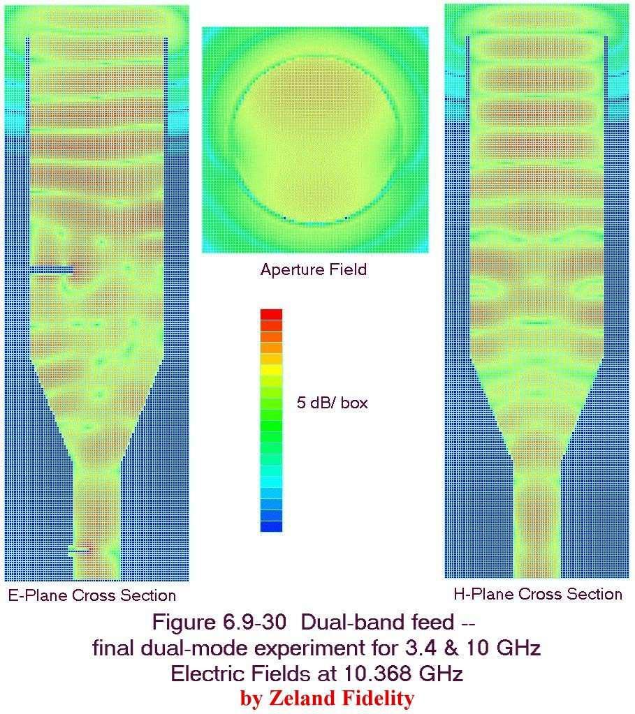
1 6.9.6 Dual-band feed experiments I was impressed with the performance of the dual-band feeds for 10 and 24 GHz; I hypothesized that the wider frequency separation might provide better results than the more closely spaced frequencies of the W5LUA feeds. A few experiments, at least in computer simulation, could test this hypothesis. Two of the possible pairs of bands with wider separation are 2304 and 5760 MHz, a 2.5:1 frequency ratio, and 3456 and MHz, a 3:1 frequency ratio. Since WR-90 waveguide for 10 GHz is readily available, perhaps we could scale the W5ZN feed to 3456 MHz and 10 GHz, by adding a waveguide to the rear of a coffee-can feed. I calculated radiation patterns using the Zeland Fidelity 3D-simulation program; performance was just like a coffeecan feed at 3456 MHz, but disastrous at 10 GHz the patterns are distorted, with a large null around the boresight. Perhaps the 3:1 frequency difference from 3456 to MHz is too large, since from to MHz is only a 2.33:1 ratio. A closer match is 2304 to 5760 MHz, a 2.5:1 ratio. I modeled this combination by grafting together the dimensions of the 2304 MHz and the 5760 MHz sections of the two W5LUA feeds, joined by a simple step transition. The radiation patterns calculated by the Fidelity 3D-simulation program are much more promising for this experiment. At 2304 MHz, the performance shown in Figure is similar to a coffee-can feed, with good efficiency and best f/d in the 0.35 to 0.45 range. At 5760 MHz, calculated efficiency in Figure is also good in spite of slight phase error, with best f/d is in the 0.45 to 0.55 range. Phase center is at the center of the aperture at 2304 MHz, but about 0.35λ in front of the aperture, outside the horn, at 5760 MHz. For a compromise f/d of about 0.45, we might expect up to 50% efficiency on both bands. If a feed for this frequency combination were needed, this second dual-band experiment would be worth trying; a bit of work is required to get the feedpoints matched on both bands. Why does the second experiment work but not the first one? Perhaps comparison of the fields inside the feeds might provide some insight the 3D simulator can display these fields. First, we will examine the electric field inside the W5ZN dualband feed at 10 GHz, in Figure , with a crosssection along the E-plane, slicing through the probe, on the left. A cross-section along the H-plane, through the center of the horn perpendicular to the probe, is on the right, and a slice across the aperture is in the middle (the probe is vertical in this orientation). The energy propagates smoothly down the circular waveguide, with only a small amount entering the small rectangular waveguide at the back, so the fields are very similar to a plain coffee-can feed. In the H-plane, the aperture field is concentrated in the center, providing a clear phase center for radiation. On the other hand, in the E-plane, the field extends across the aperture with high field intensity at the rim of the horn, causing the edge currents and sidelobes we previously noted in simple feeds. The field in the aperture clearly shows that we are propagating the dominant TE mode: compare the aperture field in Figure with Figure 6.5-5a. 11 In the former, a high electric field is indicated by red coloring, while in the latter, a high field is indicated by closely-spaced arrows.
2 Feed Radiation Pattern Dual-band feedhorn for 2304 & 5760 at 2304 MHz, by Zeland Fidelity Figure E-plane 0 db H-plane Dish diameter = 10 λ Feed diameter = 1 λ Feed Phase Angle 90 E-plane 67.5 H-plane Rotation Angle around specified Phase Center = 0.14 λ beyond aperture Parabolic Dish Efficiency % MAX Possible Efficiency with Phase error MAX Efficiency without phase error AFTER LOSSES: REAL WORLD at least 15% lower Illumination Spillover Feed Blockage 1 db 2 db 3 db 4 db 5 db 6 db 7 db 8 db Parabolic Dish f/d W1GHZ 1998
3 Feed Radiation Pattern Dual-band feedhorn for 2304 & 5760 at 5760 MHz, by Zeland Fidelity Figure E-plane 0 db H-plane Dish diameter = 25 λ Feed diameter = 2.5 λ Feed Phase Angle 90 E-plane 67.5 H-plane Rotation Angle around specified Phase Center = 0.35 λ beyond aperture Parabolic Dish Efficiency % MAX Possible Efficiency with Phase error MAX Efficiency without phase error AFTER LOSSES: REAL WORLD at least 15% lower Illumination Spillover Feed Blockage 1 db 2 db 3 db 4 db 5 db 6 db 7 db 8 db Parabolic Dish f/d W1GHZ 1998

4 Figure shows the fields inside the W5ZN dual-band feed at 24 GHz. The fields in the E- and H-plane cross-sections start out in the small waveguide, then show some evidence that additional modes are excited by the step to the larger diameter section. Apparently all the modes arrive in phase at the aperture, since the aperture field is similar to that of a coffee-can feed. Having examined the fields in a good dual-band feed, we can return to our unsuccessful experiment, the dual-band feed for 3456 MHz and 10 GHz.. The cause of the distorted pattern is apparent from examination of the fields inside the feed, shown at 10 GHz in Figure Higher-order waveguide modes are being excited by the large step from the smaller rectangular to the larger circular waveguide, and are propagating in the larger section. At the aperture, the field in Figure looks like the TM mode; see Figure 6.5-5b for a sketch of this mode. The field is very small at the center 11 of the waveguide, so there is little energy radiated straight ahead; most goes in unwanted directions.

5 Our second experimental dual-band feed, for 2304 and 5760 MHz, is better. The fields at 5760 MHz in Figure show that additional modes are being excited by the step change in diameter and propagated, but they apparently arrive at the aperture in a phase relation with maximum energy at the center, so that the radiation pattern is usable. The aperture field in does show mode irregularities and assymetry between the E- and H-planes that contribute to the phase error we saw in Figure

6 Now we can see that we must find a set of dimensions so that any modes that are excited arrive at the aperture with magnitudes and phases that provide a reasonable radiation pattern. I returned to the first experimental feed and tried some modifications. First, a longer large-diameter section to improve 10 GHz phasing showed no significant improvement. Next, I changed the 10 GHz back section to a cylindrical waveguide and added a flared transition section to make it a dual-mode feed at 10 GHz this one showed some improvement, but higher-order modes were still propagating and distorting the pattern. Finally, I reduced the diameter of the large section to 0.68λ at 3456 MHz, as small as I felt would provide a good pattern at that band, and then used HDL_ANT to calculate the best flare dimensions for dual-mode operation at 10 GHz. The final combination works better the fields at GHz in Figure show that the some undesired modes are excited by the flare but cannot propagate in the reduced diameter of the larger section; note how the fields become well behaved near the aperture. The resulting field at the aperture is reasonably good, but the aperture diameter is quite large in wavelengths, so that the 10 GHz radiation pattern in Figure is rather narrow, and best f/d is about 0.8. The dual-band performance is still unsatisfactory, since the radiation pattern at 3456 MHz in Figure is broad like a coffee-can feed, with best calculated efficiency at an f/d of about 0.4. No good compromise for f/d seems likely, due to the difference in patterns at the two frequencies.

7 The lesson we might learn from these dual-band feed experiments is that designing a good dual-band feedhorn is difficult and requires a lot of time, either experimental or computer time. W5LUA and W5ZN should be commended for their efforts.
8
9 Feed Radiation Pattern Dualband 3 & 10 GHz feed with flare at GHz, by Zeland Fidelity Figure E-plane 0 db H-plane Dish diameter = 30 λ Feed diameter = 2.04 λ Feed Phase Angle 90 E-plane 67.5 H-plane Rotation Angle around specified Phase Center = 0.3 λ inside aperture Parabolic Dish Efficiency % MAX Possible Efficiency with Phase error MAX Efficiency without phase error AFTER LOSSES: REAL WORLD at least 15% lower Illumination Spillover Feed Blockage 1 db 2 db 3 db 4 db 5 db 6 db 7 db 8 db Parabolic Dish f/d W1GHZ 1998
10 Feed Radiation Pattern Dualband 3 & 10 GHz feedhorn with flare at 3456 MHz, by Zeland Fidelity Figure E-plane 0 db H-plane Dish diameter = 10 λ Feed diameter = 0.68 λ Feed Phase Angle 90 E-plane 67.5 H-plane Rotation Angle around specified Phase Center = 0.1 λ inside aperture Parabolic Dish Efficiency % MAX Possible Efficiency with Phase error MAX Efficiency without phase error AFTER LOSSES: REAL WORLD at least 15% lower Illumination Spillover Feed Blockage 1 db 2 db 3 db 4 db 5 db 6 db 7 db 8 db Parabolic Dish f/d W1GHZ 1998

11 6.9.7 Broadband feeds There are two common types of broadband microwave antennas, log-periodic arrays and ridgedwaveguide horns. For both, broadband means having some nominal gain and input match over a range of frequency; it does not necessarily mean have a well-controlled radiation pattern at every frequency in that range. The log-periodic antenna is a travelling-wave antenna with tapered element lengths, so that a few of the elements are active at each frequency. Antenna handbooks 14 often describe a microwave version with the elements cut in a flat plate, rather than individual rods, called a trapezoidal-tooth logperiodic. W2IMU once told me that log-periodic arrays have poor phase-center characteristics, and I ve never seen anything to contradict him. WA1MBA investigated log-periodic arrays as feed antennas 15 and built some of the trapeziodal-tooth variety to cover the bands from 2304 to 10 GHz. Figure is a photograph of one. When we made gain measurements on a dish with this feed, efficiency at 10 GHz was poor, under 40%. Ridged-waveguide horns are rectangular or conical horns flared from waveguide of the same cross section. The ridges are added to waveguide to increase the cutoff frequency for higher-order modes, thus increasing the usable bandwidth of the dominant mode. If ridges are extended into the flare, the horn may have the same usable bandwidth as the waveguide. I have seen surplus conical horns with four ridges, every 90 around the perimeter, labeled 2 to 18 GHz. A feedhorn using this type of construction claimed 16 to have an octave bandwidth and to provide a constant secondary (dish) beamwidth over the bandwidth but dish beamwidth should decrease with increasing frequency if the performance is good. Radiation patterns were only published for the ends of the octave but had much different beamwidths, suggesting that the feed underilluminated the reflector at the upper end of the band. Rectangular ridged-waveguide horns can also provide very wide bandwidths. One paper 17 described versions covering 1 to 12 GHz and 0.2 to 20 GHz with nominal 12 db gain. However, sample patterns at several frequencies were very inconsistent, suggesting that this would not be a good broadband feedhorn.

12 The Antenna Engineering Handbook 14 recommends a planar sinous antenna as a feed, claiming it provides a constant beamwidth in the E- and H-planes and a frequency independent phase center. Unfortunately, only a sketch is given, with few details and no performance results. I have not found any other references for this antenna. Although these broadband antennas may not have useful radiation patterns over the whole bandwidth, there are probably smaller frequency ranges where the pattern is acceptable. Someone with a lot of excess time on a powerful computer could probably find dimensions to put the better patterns in the microwave ham bands. Since the broadband antennas typically have moderate gain, 10 db or so, the beamwidth is more suitable for a higher f/d. Thus, an offset dish might be a better target for broadband feed design Multi-band feed assemblies An alternative to a multi-band feed is to have multiple feeds on one parabolic reflector. A good example of this technique is used by VE1ALQ 18 for EME operation on 432 and 1296 MHz. The feed is shown in the photograph of Figure a combination of an EIA dual-dipole feed (Section 6.2.2) for 432 MHz and an N7ART diagonal feed (Section 6.5.3) for 1296 MHz. The physically-small diagonal feed in the center should have little effect at 432, while the two dipoles are so widely spaced that they are hardly in the pattern of the 1296 MHz feed. One feature of this combination is that the dimensions of each feed can be adjusted for best illumination over a range of f/d, and the phase center of each feed can be individually located at the focus of the dish.

13 The VE1ALQ feed above is a good example, but it would be difficult to have more than two bands with a common phase center. Perhaps a dual-band feed could be used at the center, for a total of three bands. On a large dish, several feeds could be mounted side-by-side, requiring rotation of the dish when changing bands to compensate for the off-axis feed. The best focal distance for an off-axis feed is on a curve called a Petzval surface 19. A combination of dual-band feeds could add up to a good multiband antenna, but the operational difficulty of dish movement when changing bands is problematic, particularly with very weak signals (the interesting ones!). A better alternative might be movable feeds, with a mechanism to move the desired feed into position. Large radiotelescopes often have movable feed arrangements, but they are large enough to tolerate a small room full of equipment behind the feed with little blockage. Most amateurs must get by with much smaller dishes, so a good alternative is the offset-fed dish, where the feed mechanism and unused feeds can be positioned out of the beam. One such feed mechanism, by WD4MUO 20, is shown in the photograph of Figure , although John s example has feedhorns more suitable for a prime-focus dish. Several waveguides for different bands feed into the lower plate. The upper plate moves the desired horn into position, with a waveguide bend connecting from the horn to the proper location on the upper plate to match the feed waveguide. Obviously, some careful machining is required for everything to line up properly. A somewhat simpler approach is used by KA1ZE on his latest rovermobile. The feeds are rotated into position by a standard antenna rotor, which has enough power to rotate both the feeds and a transverter for each band. Figure shows the assembly; the rotor and all the equipment are out of the beam of the offset dish. One problem that Stan found was that the obliquely-mounted rotor had too much slop to reliably position the feedhorns at the dish focus rotors are designed for vertical mounting. He added the plastic bearing above the feeds to remove the slop.

14 A final choice, where the dish is accessible, is to make the feeds easily interchangeable. WA5VJB has such a mechanism on his EME dish, fashioned from plastic plumbing fixtures. On EME, there is usually adequate time between schedules for a quick feed change Summary Multi-band feeds are never as good as the best single-band feeds, but some two-band feeds can provide performance that is acceptably close. For many amateur installations, having an additional band without requiring an extra dish is a good compromise. Another useful feature is he ability to aim the dish on a lower band, then switch to a higher band without disturbing the dish. However, for EME, where every db is essential, co-located feeds or interchangeable feeds might be a better choice.
15 6.9 References 1. J. Harrison, W5ZN, Horns for the Holidays, Proceedings of Microwave Update 97, ARRL, 1997, pp J. Harrison, W5ZN, W5ZN Dual Band 10 GHz / 24 GHz Feedhorn, Proceedings of Microwave Update 98, ARRL, 1998, pp J. Harrison, W5ZN, Further Evaluation of the W5LUA & W5ZN Dual Band Feeds, Proceedings of Microwave Update 99, ARRL, 1999, pp T. Hill, WA3RMX, A Triband Microwave Dish Feed, QST, Aug. 1990, pp Zeland Software, Inc K. Britain, WA5VJB, Dual Band Dish Feeds, Proceedings of Microwave Update 91, ARRL, 1991, pp G.J.Burke & A.J. Poggio, Numerical Electromagnetic Code (NEC) Method of Moments, Lawrence Livermore Laboratory, P. Wade, N1BWT, Dual-band Feedhorn for the DSS Offset Dish, Proceedings of the 23 rd Eastern VHF/UHF Conference, ARRL, 1997, pp D. Evans, G3RPE, Pyramidal horn feeds for paraboloidal dishes, Radio Communications, March also in: 10. M.W. Dixon, G3PFR, Microwave Handbook, Volume 3, RSGB, 1992, p A. Ward, WB5LUA, Dual Band Feedhorns for 2304/3456 MHz and 5760/10368 MHz, Proceedings of Microwave Update 97, ARRL, 1997 pp W.A. Imbriale, P.G. Ingerson, and W.C. Wong, Experimental Verification of the Analysis of Umbrella Parabolic Reflectors, IEEE Transactions on Antennas and Propagation, September 1973, pp R.H. DuHamel & J.P. Scherer, Frequency-Independent Antennas, in R.C. Johnson, Antenna Engineering Handbook, McGraw-Hill, 1993, pp to T. Williams, WA1MBA, A Broadband Dish Feed for Amateur Radio SHF, Proceedings of Microwave Update 94, ARRL, 1994, pp J.K. Shimizu, Octave bandwidth feed horn for paraboloid, IRE Transactions on Antennas and Propagation, March 1961, pp
16 17. J.L. Kerr, Short Axial Length Broad-Band Horns, IEEE Transactions on Antennas and Propagation, September 1973, pp C. Scott, Modern Methods of Reflector Antenna Analysis and Design, Artech House, 1990, pp J.E. Anderson, WD4MUO/0, Switched Feeds for Multi-band Parabolic Antennas, Proceedings of Microwave Update 99, ARRL, 1999, pp
6.1.5 Dish Patterns with Axial Displacement Error
 6.1.5 Dish Patterns with Axial Displacement Error When I first talked about axial displacement error, one of the first questions that arose was Where does the power go when the gain is reduced? The best
W1GHZ W1GHZ W1GHZ W1GHZ W1GHZ W1GHZ W1GHZ W1GHZ
 Online Online Online Online Online Online (ex-n1bwt) (ex-n1bwt) (ex-n1bwt) (ex-n1bwt) (ex-n1bwt) (ex-n1bwt) (ex-n1bwt) Online (ex-n1bwt) W1GHZ W1GHZ Microwave Antenna Book Antenna BookOnline W1GHZ W1GHZ
Dual Band Feedhorns for 2304/3456 MHz and 5760/10368 MHz
 Dual Band Feedhorns for 2304/3456 MHz and 5760/10368 MHz by Al Ward WB5LUA Microwave Update 97 Sandusky, Ohio Background Numerous articles have been written by WA9HUV, VE4MA, N1BWT and others on the proper
W1GHZ W1GHZ W1GHZ W1GHZ W1GHZ W1GHZ W1GHZ W1GHZ
 Online Online Online Online Online Online (ex-n1bwt) (ex-n1bwt) (ex-n1bwt) (ex-n1bwt) (ex-n1bwt) (ex-n1bwt) (ex-n1bwt) Online (ex-n1bwt) W1GHZ W1GHZ Microwave Antenna Book Antenna BookOnline W1GHZ W1GHZ
W1GHZ W1GHZ W1GHZ W1GHZ W1GHZ W1GHZ W1GHZ W1GHZ
 Section 6.0 Introduction Chapter 6 Feeds for Parabolic Dish Antennas Paul Wade 1994,1997,1998,1999 The key to good parabolic dish antenna performance is the feed antenna, the source of radiated energy
W1GHZ W1GHZ W1GHZ W1GHZ W1GHZ W1GHZ W1GHZ W1GHZ
 Online Online Online Online Online Online (ex-n1bwt) (ex-n1bwt) (ex-n1bwt) (ex-n1bwt) (ex-n1bwt) (ex-n1bwt) (ex-n1bwt) Online (ex-n1bwt) W1GHZ W1GHZ Microwave Antenna Book Antenna BookOnline W1GHZ W1GHZ
PRIME FOCUS FEEDS FOR THE COMPACT RANGE
 PRIME FOCUS FEEDS FOR THE COMPACT RANGE John R. Jones Prime focus fed paraboloidal reflector compact ranges are used to provide plane wave illumination indoors at small range lengths for antenna and radar
Aperture Antennas. Reflectors, horns. High Gain Nearly real input impedance. Huygens Principle
 Antennas 97 Aperture Antennas Reflectors, horns. High Gain Nearly real input impedance Huygens Principle Each point of a wave front is a secondary source of spherical waves. 97 Antennas 98 Equivalence
7.2.8 Frequency sensitivity
 7.2.8 Frequency sensitivity To evaluate the effect of frequency error on the antenna performance, I also calculated the radiation patterns for the 16-slot antenna at 9.0 GHz and 11.736 GHz. The resulting
essential requirements is to achieve very high cross-polarization discrimination over a
 INTRODUCTION CHAPTER-1 1.1 BACKGROUND The antennas used for specific applications in satellite communications, remote sensing, radar and radio astronomy have several special requirements. One of the essential
Basic Microwave Antennas - Utility-Driven Tradeoff Analysis. Tom Haddon, K5VH
 Basic Microwave Antennas - Utility-Driven Tradeoff Analysis Tom Haddon, K5VH So, You Want to Get On the Microwave Bands? What Antenna? How do I Decide? Build or Buy? Cost? How Hard to Install? How Good?
RA3AQ Septum Feed Simulations
 RA3AQ Septum Feed Simulations Paul Wade W1GHZ 2008 w1ghz@arrl.net Dmitri, RA3AQ developed a feed in 2007 with a square septum and a round aperture, and updated it in late 2008. I received this drawing
Newsletter 2.3. Antenna Magus version 2.3 released! New antennas in Version 2.3. Potter horn. Circularly polarised rectangular-biquad antenna
 Newsletter 2.3 October 2010 Antenna Magus version 2.3 released! An update to Antenna Magus, version 2.3, is now available for download. This update features 10 new antennas, as opposed to the usual 6.
Newsletter 2.0. Antenna Magus version 2.0 released! New Array synthesis tool. April 2010
 Newsletter 2.0 April 2010 Antenna Magus version 2.0 released! We are very proud to announce the second major release of Antenna Magus, Version 2.0. Looking back over the past 11 months since release 1.0
Computer Optimized Dual Mode Circularly Polarized Feedhorn
 Computer Optimized Dual Mode Circularly Polarized Feedhorn Marc Franco, N2UO 1 - Introduction This paper presents a high efficiency horn antenna intended to illuminate a passive parabolic reflector. The
The magnetic surface current density is defined in terms of the electric field at an aperture as follows: 2E n (6.1)
") Chapter 6. Aperture antennas Antennas where radiation occurs from an open aperture are called aperture antennas. xamples include slot antennas, open-ended waveguides, rectangular and circular horn antennas,
Chapter 6. Aperture antennas Antennas where radiation occurs from an open aperture are called aperture antennas. xamples include slot antennas, open-ended waveguides, rectangular and circular horn antennas,
PLANE-WAVE SYNTHESIS FOR COMPACT ANTENNA TEST RANGE BY FEED SCANNING
 Progress In Electromagnetics Research M, Vol. 22, 245 258, 2012 PLANE-WAVE SYNTHESIS FOR COMPACT ANTENNA TEST RANGE BY FEED SCANNING H. Wang 1, *, J. Miao 2, J. Jiang 3, and R. Wang 1 1 Beijing Huahang
Reflector antennas and their feeds
 Reflector antennas and their feeds P. Hazdra, M. Mazanek,. hazdrap@fel.cvut.cz Department of Electromagnetic Field Czech Technical University in Prague, FEE www.elmag.org v. 23.4.2015 Outline Simple reflector
Chapter 41 Deep Space Station 13: Venus
 Chapter 41 Deep Space Station 13: Venus The Venus site began operation in Goldstone, California, in 1962 as the Deep Space Network (DSN) research and development (R&D) station and is named for its first
Reflector Antenna, its Mount and Microwave. Absorbers for IIP Radiometer Experiments
 Reflector Antenna, its Mount and Microwave Absorbers for IIP Radiometer Experiments Nakasit Niltawach, and Joel T. Johnson May 8 th, 2003 1 Introduction As mentioned in [1], measurements are required for
A Novel 5 Step Septum Feed Suite
 A Novel 5 Step Septum Feed Suite Swedish EME-meeting May 2013 SM6FHZ and SM6PGP Updated Post Conference Edition Outline Prerequisite Features Design criteria / considerations Wave Guides Septum Kumar choke,
Design of Tri-frequency Mode Transducer
 78 Design of Tri-frequency Mode Transducer V. K. Singh, S. B. Chakrabarty Microwave Sensors Antenna Division, Antenna Systems Area, Space Applications Centre, Indian Space Research Organization, Ahmedabad-3815,
A NEW WIDEBAND DUAL LINEAR FEED FOR PRIME FOCUS COMPACT RANGES
 A NEW WIDEBAND DUAL LINEAR FEED FOR PRIME FOCUS COMPACT RANGES by Ray Lewis and James H. Cook, Jr. ABSTRACT Performance trade-offs are Investigated between the use of clustered waveguide bandwidth feeds
COMPARATIVE ANALYSIS BETWEEN CONICAL AND GAUSSIAN PROFILED HORN ANTENNAS
 Progress In Electromagnetics Research, PIER 38, 147 166, 22 COMPARATIVE ANALYSIS BETWEEN CONICAL AND GAUSSIAN PROFILED HORN ANTENNAS A. A. Kishk and C.-S. Lim Department of Electrical Engineering The University
Design of a Novel Compact Cup Feed for Parabolic Reflector Antennas
 Progress In Electromagnetics Research Letters, Vol. 64, 81 86, 2016 Design of a Novel Compact Cup Feed for Parabolic Reflector Antennas Amir Moallemizadeh 1,R.Saraf-Shirazi 2, and Mohammad Bod 2, * Abstract
Broadband and High Efficiency Single-Layer Reflectarray Using Circular Ring Attached Two Sets of Phase-Delay Lines
 Progress In Electromagnetics Research M, Vol. 66, 193 202, 2018 Broadband and High Efficiency Single-Layer Reflectarray Using Circular Ring Attached Two Sets of Phase-Delay Lines Fei Xue 1, *, Hongjian
A Novel 5 Step Septum Feed Suite
 A Novel 5 Step Septum Feed Suite Swedish EME-meeting May 2013 SM6FHZ and SM6PGP Updated Post Conference Edition Outline Prerequisite Features Design criteria / considerations Wave Guides Septum Kumar choke,
SEPTUM HORN ANTENNAS AT 47/48 GHz FOR HIGH ALTITUDE PLATFORM STATIONS
 SEPTUM HORN ANTENNAS AT 47/48 GHz FOR HIGH ALTITUDE PLATFORM STATIONS Z. Hradecky, P. Pechac, M. Mazanek, R. Galuscak CTU Prague, FEE, Dept. of Electromagnetic Field, Technicka 2, 166 27 Prague, Czech
ANTENNA INTRODUCTION / BASICS
 ANTENNA INTRODUCTION / BASICS RULES OF THUMB: 1. The Gain of an antenna with losses is given by: 2. Gain of rectangular X-Band Aperture G = 1.4 LW L = length of aperture in cm Where: W = width of aperture
Microstrip Antennas Integrated with Horn Antennas
 53 Microstrip Antennas Integrated with Horn Antennas Girish Kumar *1, K. P. Ray 2 and Amit A. Deshmukh 1 1. Department of Electrical Engineering, I.I.T. Bombay, Powai, Mumbai 400 076, India Phone: 91 22
RESEARCH AND DESIGN OF QUADRUPLE-RIDGED HORN ANTENNA. of Aeronautics and Astronautics, Nanjing , China
 Progress In Electromagnetics Research Letters, Vol. 37, 21 28, 2013 RESEARCH AND DESIGN OF QUADRUPLE-RIDGED HORN ANTENNA Jianhua Liu 1, Yonggang Zhou 1, 2, *, and Jun Zhu 1 1 College of Electronic and
KULLIYYAH OF ENGINEERING
 KULLIYYAH OF ENGINEERING DEPARTMENT OF ELECTRICAL & COMPUTER ENGINEERING ANTENNA AND WAVE PROPAGATION LABORATORY (ECE 4103) EXPERIMENT NO 3 RADIATION PATTERN AND GAIN CHARACTERISTICS OF THE DISH (PARABOLIC)
Newsletter 5.4. New Antennas. The profiled horns. Antenna Magus Version 5.4 released! May 2015
 Newsletter 5.4 May 215 Antenna Magus Version 5.4 released! Version 5.4 sees the release of eleven new antennas (taking the total number of antennas to 277) as well as a number of new features, improvements
TRANSMITTING ANTENNA WITH DUAL CIRCULAR POLARISATION FOR INDOOR ANTENNA MEASUREMENT RANGE
 TRANSMITTING ANTENNA WITH DUAL CIRCULAR POLARISATION FOR INDOOR ANTENNA MEASUREMENT RANGE Michal Mrnka, Jan Vélim Doctoral Degree Programme (2), FEEC BUT E-mail: xmrnka01@stud.feec.vutbr.cz, velim@phd.feec.vutbr.cz
Design of a prime-focus feed with backward radiation
 Design of a prime-focus feed with backward radiation Libor SLÁMA 1, Rastislav GALUŠČÁK - OM6AA 1, Pavel HAZDRA 1 1 Dept. of Electromagnetic Field, Czech Technical University, Technická 2, 166 27 Praha,
Design and realization of tracking feed antenna system
 Design and realization of tracking feed antenna system S. H. Mohseni Armaki 1, F. Hojat Kashani 1, J. R. Mohassel 2, and M. Naser-Moghadasi 3a) 1 Electrical engineering faculty, Iran University of science
- reduce cross-polarization levels produced by reflector feeds - produce nearly identical E- and H-plane patterns of feeds
 Corrugated Horns Motivation: Contents - reduce cross-polarization levels produced by reflector feeds - produce nearly identical E- and H-plane patterns of feeds 1. General horn antenna applications 2.
Performance Analysis of a Patch Antenna Array Feed For A Satellite C-Band Dish Antenna
 Cyber Journals: Multidisciplinary Journals in Science and Technology, Journal of Selected Areas in Telecommunications (JSAT), November Edition, 2011 Performance Analysis of a Patch Antenna Array Feed For
Dr. John S. Seybold. November 9, IEEE Melbourne COM/SP AP/MTT Chapters
 Antennas Dr. John S. Seybold November 9, 004 IEEE Melbourne COM/SP AP/MTT Chapters Introduction The antenna is the air interface of a communication system An antenna is an electrical conductor or system
A DUAL-PORTED PROBE FOR PLANAR NEAR-FIELD MEASUREMENTS
 A DUAL-PORTED PROBE FOR PLANAR NEAR-FIELD MEASUREMENTS W. Keith Dishman, Doren W. Hess, and A. Renee Koster ABSTRACT A dual-linearly polarized probe developed for use in planar near-field antenna measurements
L-Band and X-Band Antenna Design and Development for NeXtRAD
 L-Band and X-Band Antenna Design and Development for NeXtRAD S. T. Paine, P. Cheng, D. W. O Hagan, M. R. Inggs, H. D. Griffiths* Department of Electrical Engineering Radar Remote Sensing Group University
ANTENNA INTRODUCTION / BASICS
 Rules of Thumb: 1. The Gain of an antenna with losses is given by: G 0A 8 Where 0 ' Efficiency A ' Physical aperture area 8 ' wavelength ANTENNA INTRODUCTION / BASICS another is:. Gain of rectangular X-Band
Keywords Cross-polarization, phasing length, return loss, multimode horn
 Volume 4, Issue, February 014 ISSN: 18X International Journal of Advanced Research in Computer Science and Software Engineering Research Paper Available online at: www.ijarcsse.com Cross Polarization Reduction
LE/ESSE Payload Design
 LE/ESSE4360 - Payload Design 4.3 Communications Satellite Payload - Hardware Elements Earth, Moon, Mars, and Beyond Dr. Jinjun Shan, Professor of Space Engineering Department of Earth and Space Science
REPORT ITU-R SA.2098
 Rep. ITU-R SA.2098 1 REPORT ITU-R SA.2098 Mathematical gain models of large-aperture space research service earth station antennas for compatibility analysis involving a large number of distributed interference
Chalmers Publication Library
 Chalmers Publication Library Analysis of the strut and feed blockage effects in radio telescopes with compact UWB feeds This document has been downloaded from Chalmers Publication Library (CPL). It is
EMG4066:Antennas and Propagation Exp 1:ANTENNAS MMU:FOE. To study the radiation pattern characteristics of various types of antennas.
 OBJECTIVES To study the radiation pattern characteristics of various types of antennas. APPARATUS Microwave Source Rotating Antenna Platform Measurement Interface Transmitting Horn Antenna Dipole and Yagi
NUMERICAL OPTIMIZATION OF A SATELLITE SHF NULLING MULTIPLE BEAM ANTENNA
 NUMERICAL OPTIMIZATION OF A SATELLITE SHF NULLING MULTIPLE BEAM ANTENNA D. Maiarelli (1), R. Guidi (2), G. Galgani (2), V. Lubrano (1), M. Bandinelli (2) (1) Alcatel Alenia Space Italia, via Saccomuro,
3 D Corner Reflector Antenna as an efficient feed for offset parabolic antennas for 5.8 GHz Dragoslav Dobričić, YU1AW
 3 D Corner Reflector Antenna as an efficient feed for offset parabolic antennas for 5.8 GHz Dragoslav Dobričić, YU1AW Abstract I n this article I present a modification of 3D corner reflector antenna in
RADIATION PATTERNS. The half-power (-3 db) beamwidth is a measure of the directivity of the antenna.
 beamwidth is a measure of the directivity of the antenna.") RADIATION PATTERNS The radiation pattern is a graphical depiction of the relative field strength transmitted from or received by the antenna. Antenna radiation patterns are taken at one frequency, one
RADIATION PATTERNS The radiation pattern is a graphical depiction of the relative field strength transmitted from or received by the antenna. Antenna radiation patterns are taken at one frequency, one
A DUAL-PORTED, DUAL-POLARIZED SPHERICAL NEAR-FIELD PROBE
 A DUAL-PORTED, DUAL-POLARIZED SPHERICAL NEAR-FIELD PROBE by J. R. Jones and D. P. Hardin Scientific-Atlanta, Inc. Spherical near-field testing of antennas requires the acquisition of a great volume of
School of Electrical Engineering. EI2400 Applied Antenna Theory Lecture 8: Reflector antennas
 School of Electrical Engineering EI2400 Applied Antenna Theory Lecture 8: Reflector antennas Reflector antennas Reflectors are widely used in communications, radar and radio astronomy. The largest reflector
Newsletter 4.4. Antenna Magus version 4.4 released! Array synthesis reflective ground plane addition. July 2013
 Newsletter 4.4 July 2013 Antenna Magus version 4.4 released! We are pleased to announce the new release of Antenna Magus Version 4.4. This release sees the addition of 5 new antennas: Horn-fed truncated
TOPIC 2 WAVEGUIDE AND COMPONENTS
 TOPIC 2 WAVEGUIDE AND COMPONENTS COURSE LEARNING OUTCOME (CLO) CLO1 Explain clearly the generation of microwave, the effects of microwave radiation and the propagation of electromagnetic in a waveguide
S.R.M. Institute of Science & Technology Deemed University School of Electronics & Communication Engineering
 S.R.M. Institute of Science & Technology Deemed University School of Electronics & Communication Engineering Question Bank Subject Code : EC401 Subject Name : Antennas and Wave Propagation Year & Sem :
CIRCULAR DUAL-POLARISED WIDEBAND ARRAYS FOR DIRECTION FINDING
 CIRCULAR DUAL-POLARISED WIDEBAND ARRAYS FOR DIRECTION FINDING M.S. Jessup Roke Manor Research Limited, UK. Email: michael.jessup@roke.co.uk. Fax: +44 (0)1794 833433 Keywords: DF, Vivaldi, Beamforming,
Evaluation of Suitable Feed Systemes
 Evaluation of Suitable Feed Systemes Review of the Ring Focus Antenna Quadridge Horn Eleven Feed Coaxial Horn and Multiband Corrugated Horn Conclusion MIRAD Microwave AG Broadband Feedsystems IVS VLBI21
CHAPTER 3 SIDELOBE PERFORMANCE OF REFLECTOR / ANTENNAS
 16 CHAPTER 3 SIDELOBE PERFORMANCE OF REFLECTOR / ANTENNAS 3.1 INTRODUCTION In the past many authors have investigated the effects of amplitude and phase distributions over the apertures of both array antennas
Introduction to Radar Systems. Radar Antennas. MIT Lincoln Laboratory. Radar Antennas - 1 PRH 6/18/02
 Introduction to Radar Systems Radar Antennas Radar Antennas - 1 Disclaimer of Endorsement and Liability The video courseware and accompanying viewgraphs presented on this server were prepared as an account
The Excitement & Challenges of 24 GHz EME. By Al Ward W5LUA August 17, 2012
 The Excitement & Challenges of 24 GHz EME By Al Ward W5LUA August 17, 2012 Introduction History Early Activity Present Activity Equipment Challenges Summary The First 24 GHz EME QSO The First 24 GHz EME
Antennas & wave Propagation ASSIGNMENT-I
 Shri Vishnu Engineering College for Women :: Bhimavaram Department of Electronics & Communication Engineering Antennas & wave Propagation 1. Define the terms: i. Antenna Aperture ii. Beam Width iii. Aperture
REMOVAL OF BEAM SQUINTING EFFECTS IN A CIRCULARLY POLARIZED OFFSET PARABOLIC REFLECTOR ANTENNA USING A MATCHED FEED
 Progress In Electromagnetics Research Letters, Vol. 7, 105 114, 2009 REMOVAL OF BEAM SQUINTING EFFECTS IN A CIRCULARLY POLARIZED OFFSET PARABOLIC REFLECTOR ANTENNA USING A MATCHED FEED S. B. Sharma Antenna
The Basics of Patch Antennas, Updated
 The Basics of Patch Antennas, Updated By D. Orban and G.J.K. Moernaut, Orban Microwave Products www.orbanmicrowave.com Introduction This article introduces the basic concepts of patch antennas. We use
MICROWAVE MICROWAVE TRAINING BENCH COMPONENT SPECIFICATIONS:
 Microwave section consists of Basic Microwave Training Bench, Advance Microwave Training Bench and Microwave Communication Training System. Microwave Training System is used to study all the concepts of
ENHANCEMENT OF PHASED ARRAY SIZE AND RADIATION PROPERTIES USING STAGGERED ARRAY CONFIGURATIONS
 Progress In Electromagnetics Research C, Vol. 39, 49 6, 213 ENHANCEMENT OF PHASED ARRAY SIZE AND RADIATION PROPERTIES USING STAGGERED ARRAY CONFIGURATIONS Abdelnasser A. Eldek * Department of Computer
Antennas and Propagation. Chapter 4: Antenna Types
 Antennas and Propagation : Antenna Types 4.4 Aperture Antennas High microwave frequencies Thin wires and dielectrics cause loss Coaxial lines: may have 10dB per meter Waveguides often used instead Aperture
A Flip-Switch 10/24 GHz Dual Band Radio
 A Flip-Switch 10/24 GHz Dual Band Radio Gary Lauterbach, AD6FP Introduction I had a great time in my first 10 Ghz and up contest in 1999 even though I was only able to operate for a few hours on the second
Septum Feeds for 10 GHz EME. Swedish EME-meeting May 2015 SM6FHZ and SM6PGP
 Septum Feeds for 10 GHz EME Swedish EME-meeting May 2015 SM6FHZ and SM6PGP Outline Prerequisite Features Design criteria / considerations (10 pages) Wave Guides Wave Guide interface Septum Kumar choke,
An Improved Design for a 1-18 GHz Double- Ridged Guide Horn Antenna
 1 An Improved Design for a 1- Double- Ridged Guide Horn Antenna B. Jacobs, J. W. Odendaal, and J. Joubert Abstract It is a well known fact that the traditional 1- Double Ridge Guide Horn (DRGH) antenna
A. A. Kishk and A. W. Glisson Department of Electrical Engineering The University of Mississippi, University, MS 38677, USA
 Progress In Electromagnetics Research, PIER 33, 97 118, 2001 BANDWIDTH ENHANCEMENT FOR SPLIT CYLINDRICAL DIELECTRIC RESONATOR ANTENNAS A. A. Kishk and A. W. Glisson Department of Electrical Engineering
BHARATHIDASAN ENGINEERING COLLEGE NATTARAMPALLI Frequently Asked Questions (FAQ) Unit 1
 Unit 1") BHARATHIDASAN ENGINEERING COLLEGE NATTARAMPALLI 635854 Frequently Asked Questions (FAQ) Unit 1 Degree / Branch : B.E / ECE Sem / Year : 3 rd / 6 th Sub Name : Antennas & Wave Propagation Sub Code : EC6602
BHARATHIDASAN ENGINEERING COLLEGE NATTARAMPALLI 635854 Frequently Asked Questions (FAQ) Unit 1 Degree / Branch : B.E / ECE Sem / Year : 3 rd / 6 th Sub Name : Antennas & Wave Propagation Sub Code : EC6602
PARABOLIC ANTENNA MODEL MTA GHz 10.0 GHz
 INSTRUCTION MANUAL PARABOLIC ANTENNA MODEL MTA-60 1.0 GHz 10.0 GHz INSTRUCTION MANUAL THIS INSTRUCTION MANUAL AND ITS ASSOCIATED INFORMATION IS PROPRIETARY. UNAUTHORIZED REPRODUCTION IS FORBIDDEN. 1993
Log-periodic dipole antenna with low cross-polarization
 Downloaded from orbit.dtu.dk on: Feb 13, 2018 Log-periodic dipole antenna with low cross-polarization Pivnenko, Sergey Published in: Proceedings of the European Conference on Antennas and Propagation Link
Physically and Electrically Large Antennas for Antenna Pattern Measurements and Radar Cross Section Measurements in the Upper VHF and UHF bands
 Physically and Electrically Large Antennas for Antenna Pattern Measurements and Radar Cross Section Measurements in the Upper VHF and UHF bands Vince Rodriguez, PhD Product Manager, Antennas ETS-Lindgren,
Aperture antennas. Ahmed FACHAR, Universidad Politécnica de Madrid (Technical University of Madrid, UPM)
") Aperture antennas Ahmed FACHAR, ahmedfach@gr.ssr.upm.es Universidad Politécnica de Madrid (Technical University of Madrid, UPM) Outline Introduction Horn antennas Introduction Rectangular horns Conical
Aperture antennas Ahmed FACHAR, ahmedfach@gr.ssr.upm.es Universidad Politécnica de Madrid (Technical University of Madrid, UPM) Outline Introduction Horn antennas Introduction Rectangular horns Conical
United States Patent (19)
") United States Patent (19) Seavey 11 Patent Number: 4,636,798 45 Date of Patent: Jan. 13, 1987 54 (75) 73 21) 22 51 52 (58) MICROWAVE LENS FOR BEAM BROADENING WITH ANTENNA FEEDS Inventor: Assignee: Appl.
United States Patent (19) Seavey 11 Patent Number: 4,636,798 45 Date of Patent: Jan. 13, 1987 54 (75) 73 21) 22 51 52 (58) MICROWAVE LENS FOR BEAM BROADENING WITH ANTENNA FEEDS Inventor: Assignee: Appl.
VK3UM Impedance Calculator. Table of Contents
 Table of Contents Concentric Tube Ratio 3 Centered Strip Line 5 Quarter Wave transition. 6 Coaxial Lengths 7 VSWR Calculator. 8 Dish Reflection Coefficient 10 Convert Fractions to a decimal value. 12 Author
High-Power Directional Couplers with Excellent Performance That You Can Build
 High-Power Directional Couplers with Excellent Performance That You Can Build Paul Wade W1GHZ 2010 w1ghz@arrl.net A directional coupler is used to sample the RF energy travelling in a transmission line
INSTITUTE OF AERONAUTICAL ENGINEERING Dundigal, Hyderabad ELECTRONICS AND COMMUNIACTION ENGINEERING QUESTION BANK
 INSTITUTE OF AERONAUTICAL ENGINEERING Dundigal, Hyderabad - 500 04 ELECTRONICS AND COMMUNIACTION ENGINEERING QUESTION BANK Course Name : Antennas and Wave Propagation (AWP) Course Code : A50418 Class :
Full-Wave Analysis of Planar Reflectarrays with Spherical Phase Distribution for 2-D Beam-Scanning using FEKO Electromagnetic Software
 Full-Wave Analysis of Planar Reflectarrays with Spherical Phase Distribution for 2-D Beam-Scanning using FEKO Electromagnetic Software Payam Nayeri 1, Atef Z. Elsherbeni 1, and Fan Yang 1,2 1 Center of
SLOT LOADED SHORTED GAP COUPLED BROADBAND MICROSTRIP ANTENNA
 SLOT LOADED SHORTED GAP COUPLED BROADBAND MICROSTRIP ANTENNA SARTHAK SINGHAL Department of Electronics Engineering,IIT(BHU),Varanasi Abstract- In this paper the bandwidth of a conventional rectangular
Broadband Circular Polarized Antenna Loaded with AMC Structure
 Progress In Electromagnetics Research Letters, Vol. 76, 113 119, 2018 Broadband Circular Polarized Antenna Loaded with AMC Structure Yi Ren, Xiaofei Guo *,andchaoyili Abstract In this paper, a novel broadband
ANALYSIS OF ELECTRICALLY SMALL SIZE CONICAL ANTENNAS. Y. K. Yu and J. Li Temasek Laboratories National University of Singapore Singapore
 Progress In Electromagnetics Research Letters, Vol. 1, 85 92, 2008 ANALYSIS OF ELECTRICALLY SMALL SIZE CONICAL ANTENNAS Y. K. Yu and J. Li Temasek Laboratories National University of Singapore Singapore
Wideband High-Efficiency Fresnel Zone Plate Reflector Antennas Using Compact Subwavelength Dual-Dipole Unit Cells
 Progress In Electromagnetics Research C, Vol. 86, 29 39, 2018 Wideband High-Efficiency Fresnel Zone Plate Reflector Antennas Using Compact Subwavelength Dual-Dipole Unit Cells Xin Liu, Yin-Yan Chen, and
Dependence of Antenna Cross-polarization Performance on Waveguide-to-Coaxial Adapter Design
 Dependence of Antenna Cross-polarization Performance on Waveguide-to-Coaxial Adapter Design Vince Rodriguez, Edwin Barry, Steve Nichols NSI-MI Technologies Suwanee, GA, USA vrodriguez@nsi-mi.com Abstract
Study Of Phasing Distribution Characteristics Of Reflectarray Antenna Using Different Resonant Elements
 Study Of Phasing Distribution Characteristics Of Reflectarray Antenna Using Different Resonant Elements M.Y. Ismail 1* and M. F. M. Shukri 1 1 Faculty of Electrical and Electronic Engineering Universiti
Notes 21 Introduction to Antennas
 ECE 3317 Applied Electromagnetic Waves Prof. David R. Jackson Fall 018 Notes 1 Introduction to Antennas 1 Introduction to Antennas Antennas An antenna is a device that is used to transmit and/or receive
SINGLE-FEEDING CIRCULARLY POLARIZED TM 21 - MODE ANNULAR-RING MICROSTRIP ANTENNA FOR MOBILE SATELLITE COMMUNICATION
 Progress In Electromagnetics Research Letters, Vol. 20, 147 156, 2011 SINGLE-FEEDING CIRCULARLY POLARIZED TM 21 - MODE ANNULAR-RING MICROSTRIP ANTENNA FOR MOBILE SATELLITE COMMUNICATION X. Chen, G. Fu,
Multiple Reflector Dish Antennas
 Introduction Multiple Reflector Dish Antennas Paul Wade W1GHZ 2004 w1ghz@arrl.net A dish antenna with multiple reflectors, like the Cassegrain antenna at OH2AUE 1 in Figure 1, looks like an obvious solution
Progress In Electromagnetics Research Letters, Vol. 9, 75 83, 2009
 Progress In Electromagnetics Research Letters, Vol. 9, 75 83, 2009 MODE DEGENERACY IN CIRCULAR CYLINDRICAL RIDGE WAVEGUIDES A. J. Sangster Electrical & Electronic Engineering Department Heriot-Watt University
An Introduction to Antennas
 May 11, 010 An Introduction to Antennas 1 Outline Antenna definition Main parameters of an antenna Types of antennas Antenna radiation (oynting vector) Radiation pattern Far-field distance, directivity,
DOUBLE-RIDGED ANTENNA FOR WIDEBAND APPLI- CATIONS. A. R. Mallahzadeh and A. Imani Electrical Engineering Department Shahed University Tehran, Iran
 Progress In Electromagnetics Research, PIER 91, 273 285, 2009 DOUBLE-RIDGED ANTENNA FOR WIDEBAND APPLI- CATIONS A. R. Mallahzadeh and A. Imani Electrical Engineering Department Shahed University Tehran,
Characteristics of Biconical Antennas Used for EMC Measurements
 Advance Topics in Electromagnetic Compatibility Characteristics of Biconical Antennas Used for EMC Measurements Mohsen Koohestani koohestani.mohsen@epfl.ch Outline State-of-the-art of EMC Antennas Biconical
Design of Sectoral Horn Antenna with Low Side Lobe Level (S.L.L)
") Volume 117 No. 9 2017, 89-93 ISSN: 1311-8080 (printed version); ISSN: 1314-3395 (on-line version) url: http://www.ijpam.eu doi: 10.12732/ijpam.v117i9.16 ijpam.eu Design of Sectoral Horn Antenna with Low
Volume 117 No. 9 2017, 89-93 ISSN: 1311-8080 (printed version); ISSN: 1314-3395 (on-line version) url: http://www.ijpam.eu doi: 10.12732/ijpam.v117i9.16 ijpam.eu Design of Sectoral Horn Antenna with Low
CREATING THREE DUAL ISOSCELES TRIANGULAR SLOTS ON THE PATCH AND BANDWIDTH ENHANCEMENT FOR SLOTTED METAMATERIAL MICROSTRIP PATCH ANTENNA
 CREATING THREE DUAL ISOSCELES TRIANGULAR SLOTS ON THE PATCH AND BANDWIDTH ENHANCEMENT FOR SLOTTED METAMATERIAL MICROSTRIP PATCH ANTENNA BUDIPUTI ANITHA PRAVALLI, M. Tech, ASSISTANT PROFESSOR SRK INSTITUTE
Antenna Measurement Uncertainty Method for Measurements in Compact Antenna Test Ranges
 Antenna Measurement Uncertainty Method for Measurements in Compact Antenna Test Ranges Stephen Blalock & Jeffrey A. Fordham MI Technologies Suwanee, Georgia, USA Abstract Methods for determining the uncertainty
The Design of an Automated, High-Accuracy Antenna Test Facility
 The Design of an Automated, High-Accuracy Antenna Test Facility T. JUD LYON, MEMBER, IEEE, AND A. RAY HOWLAND, MEMBER, IEEE Abstract This paper presents the step-by-step application of proven far-field
ADVANCED 14/12 AND 30/20 GHz MULTIPLE BEAM ANTENNA TECHNOLOGY FOR COMMUNICATIONS SATELLITES
 ADVANCED 14/12 AND 30/20 GHz MULTIPLE BEAM ANTENNA TECHNOLOGY FOR COMMUNICATIONS SATELLITES C.C. Chen TRW Defense and Space Systems Group Redondo Beach, CA 90278 ABSTRACT This paper discusses recent TRW
Proximity fed gap-coupled half E-shaped microstrip antenna array
 Sādhanā Vol. 40, Part 1, February 2015, pp. 75 87. c Indian Academy of Sciences Proximity fed gap-coupled half E-shaped microstrip antenna array AMIT A DESHMUKH 1, and K P RAY 2 1 Department of Electronics