TOBY-L210 GSM/UMTS/HSPA/LTE Data Module
|
|
|
- Lora Mosley
- 5 years ago
- Views:
Transcription
1 FCC Measurement/Technical Report on TOBY-L210 GSM/UMTS/HSPA/LTE Data Module FCC ID: XPYTOBYL210 IC:8595A-TOBYL210 Report Reference: MDE_UBLOX_1409_FCCb Rev 02 according to FCC Part 22, Subpart H Test Laboratory: 7Layers AG Borsigstr Ratingen Germany Note: The following test results relate only to the devices specified in this document. This report shall not be reproduced in parts without the written approval of the test laboratory. 7Layers AG Aufsichtsratsvorsitzender Registergericht registered in: Borsigstrasse 11 Chairman of the Supervisory Board: Düsseldorf, HRB Ratingen, Germany Peter Mertel USt-IdNr VAT No.: Phone: +49 (0) Vorstand Board: DE Fax: +49 (0) Dr. H.-J. Meckelburg TAX No. 147/5869/ Dr. H. Ansorge
2 Table of Contents 0 Summary Technical Report Summary Measurement Summary 5 1 Administrative Data Testing Laboratory Project Data Applicant Data Manufacturer Data 6 2 Test object Data General EUT Description EUT Main components Ancillary Equipment Auxiliary Equipment EUT Setups Operating Modes Special software used for testing Product labeling 10 3 Test Results RF Power Output Frequency stability Spurious emissions at antenna terminals Emission and Occupied Bandwidth Band edge compliance Power to Average Ratio 23 4 Test Equipment 24 5 Photo Report 27 6 Setup Drawings 28 7 Annex measurement plots RF Power Output , Peak to Average Ratio RSS-132, Spurious emissions at antenna terminals , Emission and Occupied Bandwidth , Band edge compliance , Test report Reference: MDE_UBLOX_1409_FCCb Rev02 FCC Part 22, Subpart H Page 2 of 47
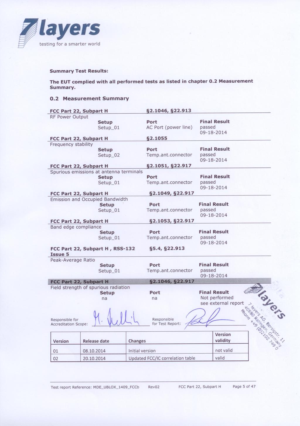
3 0 Summary 0.1 Technical Report Summary Type of Authorization Certification for a GSM/WCDMA/LTE cellular radiotelephone device. This report covers only the LTE portion of this device. Applicable FCC Rules Prepared in accordance with the requirements of FCC Rules and Regulations as listed in 47 CFR Ch.1 Parts 0 to 69. The following subparts are applicable to the results in this test report. Part 2, Subpart J - Equipment Authorization Procedures, Certification Measurement required: RF power output Measurement required: Occupied bandwidth Measurement required: Spurious emissions at antenna terminals Measurement required: Field strength of spurious radiation* Measurement required: Frequency stability Frequency spectrum to be investigated *Covered by external report. Part 22, Subpart C Operational and Technical Requirements Frequency tolerance Part 22, Subpart H Cellular Radiotelephone Service Effective radiated power limits Emission limitations for cellular equipment Additional documents Note: ANSI TIA-603-C-2004 Test report Reference: MDE_UBLOX_1409_FCCb Rev02 FCC Part 22, Subpart H Page 3 of 47
4 Correlation of measurement requirements for Cellular Equipment from FCC and IC FCC Rule / IC Standard Part 22 / RSS 132 Part 24 / RSS 133 (NA) Part 27 / RSS 139 / RSS 199 Effective (isotropic) Radiated Power RSS GEN, 4.8 RSS 132, RSS GEN, 4.8 RSS 133, (d) RSS GEN, 4.8 RSS 139; 6.4 RSS GEN, 4.8 RSS 199; 4.4 Occupied Bandwidth RSS GEN RSS GEN RSS-GEN 4.6 RSS-GEN 4.6 Spuri at Antenna Terminal RSS GEN, 4.9 RSS 132, RSS GEN, 4.9 RSS 132, (h) RSS GEN, 4.9 RSS 139, 6.5 RSS GEN, 4.9 RSS 199, 4.6 Band Edge compliance RSS GEN, RSS GEN, (h) RSS GEN, 4.6 RSS GEN, 4.6 Frequency Stability RSS-GEN, RSS GEN, 4.7 RSS 132, RSS GEN, 4.7 RSS 139, 6.3 RSS GEN, 4.7 RSS 199, 4.3 Peak to Average Ration N/A RSS-132, RSS-133, (d) RSS 139, 6.4 NA Modulation Characteristics RSS-132, RSS-133, RSS-139, 6.2 RSS-199, 4.1 Field Strength of Spurious Radiation RSS-132, RSS GEN, 4.9 RSS 133, RSS GEN, 4.9 RSS 139, 6.5 RSS GEN, 4.9 RSS 199, 4.6 *) Receivers which are part of Transceivers are exempted with respect to Notice 2012-DRS0126. Test report Reference: MDE_UBLOX_1409_FCCb Rev02 FCC Part 22, Subpart H Page 4 of 47
5
6 1 Administrative Data 1.1 Testing Laboratory Company Name: 7Layers AG Address Borsigstr Ratingen Germany This facility has been fully described in a report submitted to the FCC and accepted under the registration number The test facility is also accredited by the following accreditation organisation: Laboratory accreditation no.: DAkkS D-PL Responsible for Accreditation Scope: Dipl.-Ing. Bernhard Retka Dipl.-Ing. Robert Machulec Dipl.-Ing. Thomas Hoell Dipl.-Ing. Marco Kullik Dipl.-Ing. Andreas Petz Report Template Version: Project Data Responsible for testing and report: Date of Test(s): Date of Report: Patrick Lomax to Applicant Data Company Name: u-blox AG Address: Zürcherstrasse 68, CH-8800 Thalwil Switzerland Contact Person: Phone: Address: Mr. Giulio Comar giulio.comar@u-blox.com 1.4 Manufacturer Data Company Name: please see applicant data Address: Contact Person: Test report Reference: MDE_UBLOX_1409_FCCb Rev02 FCC Part 22, Subpart H Page 6 of 47
7 2 Test object Data 2.1 General EUT Description Equipment under Test: Type Designation: Kind of Device: (optional) Voltage Type: Voltage Level: Tested Modulation Type: GSM/UMTS/HSPA/LTE Data Module TOBY-L210 Module DC 3.8 V QPSK;16QAM General product description: The Module is able to operating in the following bands: GSM 850/ /1800 UMTS/HSDPA/HSUPA FDD1,2,5,8 LTE efdd 1,3,5,7,8,20 The EUT provides the following ports: Ports Temporary antenna connector Enclosure Test report Reference: MDE_UBLOX_1409_FCCb Rev02 FCC Part 22, Subpart H Page 7 of 47
8 2.2 EUT Main components Type, S/N, Short Descriptions etc. used in this Test Report Short Description Equipment Type Serial No. HW Status SW Status under Test Designation EUT A (Code: GSM/UMTS/ TOBY-L BA DE AX12) LTE Module EUT B (Code: DE BC13) GSM/UMTS/ LTE Module TOBY-L BA Remark: EUT A is equipped with a temporary antenna connector. The Module is not sold with a predefined antenna. NOTE: The code mentioned in short description is used to simplify the identification of the EUT in this test report. 2.3 Ancillary Equipment For the purposes of this test report, ancillary equipment is defined as equipment which is used in conjunction with the EUT to provide operational and control features to the EUT. It is necessary to configure the system in a typical fashion, as a customer would normally use it. But nevertheless Ancillary Equipment can influence the test results. Short Description AE 1 AE 2 Equipment under Test AC/DC converter Evaluation test board Type Designation UUX EVB-WL1 HW Status SW Status Serial no. FCC ID - - E HP02_HW_C BS S_ Auxiliary Equipment For the purposes of this test report, auxiliary equipment is defined as equipment which is used temporarily to enable operational and control features especially used for the tests of the EUT which is not used during normal operation or equipment that is used during the tests in combination with the EUT but is not subject of this test report. It is necessary to configure the system in a typical fashion, as a customer would normally use it. But nevertheless Auxiliary Equipment can influence the test results. Short Description Equipment under Test Type Designation Serial no. HW Status SW Status FCC ID * * No auxiliary equipment was required to operate the module Test report Reference: MDE_UBLOX_1409_FCCb Rev02 FCC Part 22, Subpart H Page 8 of 47
9 2.5 EUT Setups This chapter describes the combination of EUTs and equipment used for testing. The rationale for selecting the EUTs, ancillary and auxiliary equipment and interconnecting cables, is to test a representative configuration meeting the requirements of the referenced standards. Setup No. Combination of EUTs Description and Rationale Setup_01 EUT A + AE 1 + AE 2 setup for conducted measurements Setup_02 EUT B + AE 1 + AE 2 setup for conducted measurements 2.6 Operating Modes The below table shows the test frequencies and channels bandwidths used for testing. TEST MODE LTE efdd 5 TX / RX TX (1.4M) TX (3M) TX (5M) TX (10) RX (1.4M) RX (3M) RX (5M) RX (10M) RF Channel Low Mid High MHz MHz MHz CH CH CH MHz MHz MHz CH CH CH MHz MHz MHz CH CH CH MHz MHz MHz CH 2407 CH CH MHz MHz MHz CH 2415 CH CH MHz MHz MHz CH 2425 CH 2525 CH MHz MHz MHz CH 2450 CH 2525 CH MHz MHz MHz Test report Reference: MDE_UBLOX_1409_FCCb Rev02 FCC Part 22, Subpart H Page 9 of 47
10 Setup Number NA Test ITEM RF OUTPUT POWER FREQUENCY STABILITY OCCUPIED BANDWIDTH PEAK TO AVERAGE RATIO BAND EDGE Compliance CONDUCTED EMISSION RADIATED EMISSION efdd 5 Test configuration Channel Band width Channels tested Modulation RB Allocation 1.4 MHz 20407, 20525, QPSK, 16QAM 1RB, 3RB, 6RB 3 MHz 20415, 20525, QPSK, 16QAM 1RB, 15RB 5 MHz 1RB, 12RB, 20425, 20525, QPSK, 16QAM 25RB 10 MHz 20450, 20525, QPSK, 16QAM 1RB, 50RB QPSK 1RB 1.4 MHz 20407, 20525, QPSK, 16QAM 6RB 3 MHz 20415, 20525, QPSK, 16QAM 15RB 5 MHz 20425, 20525, QPSK, 16QAM 25RB 10 MHz 20450, 20525, QPSK, 16QAM 50RB 5 MHz 20425, 20525, QPSK, 16QAM 25RB 1.4 MHz 20407, 20525, QPSK, 16QAM 6RB / Max offset 3 MHz 15RB/ Max QPSK, 16QAM 20415, 20525, offset 5 MHz 25RB/ Max QPSK, 16QAM 20425, 20525, offset 10 MHz 50RB/ Max QPSK, 16QAM 20450, 20525, offset 5 MHz 20425, 20525, QPSK, 16QAM 1RB NA See external report NA NA 2.7 Special software used for testing - NA Software to control the EUT directly - NA Software to enable control the EUT by a signaling unit - NA 2.8 Product labeling FCC ID label Please refer to the documentation of the applicant Location of the label on the EUT Please refer to the documentation of the applicant. Test report Reference: MDE_UBLOX_1409_FCCb Rev02 FCC Part 22, Subpart H Page 10 of 47
11 3 Test Results 3.1 RF Power Output Standard FCC Part 22, Subpart H The test was performed according to: FCC Test Description (conducted procedure) 1) The EUT was coupled to a Spectrum Analyser and a Digital Communication Tester through a Power Divider. Refer to chapter "Setup Drawings". 2) The total insertion losses for signal path 1 and signal path 2 were measured. The values were used to correct the readings from the Spectrum Analyser and the Digital Communication Tester. 3) A call was established on a Traffic Channel between the EUT and the Digital Communication Tester. 4) Important Settings: 5) Channel (Frequency): please refer to the detailed results 6) The transmitted power of the EUT was recorded by using a spectrum analyser. Test Description (radiated measurement procedure) 1) The EUT was placed inside an anechoic chamber. Refer to chapter "Setup Drawings". The EUT was coupled to a Digital Communication Tester which was located outside the chamber via a small signalling antenna. 2) A call was established on a Traffic Channel between the EUT and the Digital Communication Tester. 1) Important Settings: 2) Output Power: Maximum 3) Channel: please refer to the detailed results 4) A substitution procedure is used so that the readings from the spectrum analyser are corrected and represent directly the equivalent radiated power (related to a lamda/2 dipole). 5) The output power was measured in both vertical and horizontal antenna polarisation during the call is established on the lowest channel, mid channel and on the highest channel. To find the worst case power all orientations (X, Y, Z) of the EUT have been measured. 6) The test procedure according to TIA-603-C-2004 has been considered. Test report Reference: MDE_UBLOX_1409_FCCb Rev02 FCC Part 22, Subpart H Page 11 of 47
12 3.1.2 Test Requirements / Limits Measurements Required: RF Power Output (a) For transmitters other than single sideband, independent sideband and controlled carrier radiotelephone, power output shall be measured at the RF output terminals when the transmitter is adjusted in accordance with the tune-up procedure to give the values of current and voltage on the circuit elements specified in (c)(8). The electrical characteristics of the output terminals when this test is made shall be stated Effective radiated power limits (a)(2) Maximum ERP. The ERP of mobile transmitters and auxiliary test transmitters must not exceed 7 Watts Test Protocol RMS Conducted power (dbm) FCC EIRP limit (W) IC EIRP limit per SRSP 503 (W) Maximum antenna gain (dbi) Test Band Band width Channel Modulation RB Verdict efdd5 1.4 Low QPSK RB Passed efdd5 1.4 Low QPSK RB Passed efdd5 1.4 Low QPSK RB Passed efdd5 1.4 Low 16QAM RB Passed efdd5 1.4 Low 16QAM RB Passed efdd5 1.4 MID QPSK RB Passed efdd5 1.4 MID QPSK RB Passed efdd5 1.4 MID QPSK RB Passed efdd5 1.4 MID 16QAM RB Passed efdd5 1.4 MID 16QAM RB Passed efdd5 1.4 High QPSK RB Passed efdd5 1.4 High QPSK RB Passed efdd5 1.4 High QPSK RB Passed efdd5 1.4 High 16QAM RB Passed efdd5 1.4 High 16QAM RB Passed efdd5 3 Low QPSK RB Passed efdd5 3 Low QPSK RB Passed efdd5 3 Low 16QAM RB Passed efdd5 3 Low 16QAM RB Passed efdd5 3 Mid QPSK RB Passed efdd5 3 Mid QPSK RB Passed efdd5 3 Mid 16QAM RB Passed efdd5 3 Mid 16QAM RB Passed efdd5 3 High QPSK RB Passed efdd5 3 High QPSK RB Passed Test report Reference: MDE_UBLOX_1409_FCCb Rev02 FCC Part 22, Subpart H Page 12 of 47
13 efdd5 3 High 16QAM RB Passed efdd5 3 High 16QAM RB Passed efdd5 5 Low QPSK RB Passed efdd5 5 Low QPSK RB Passed efdd5 5 Low QPSK RB Passed efdd5 5 Low 16QAM RB Passed efdd5 5 Low 16QAM RB Passed efdd5 5 MID QPSK RB Passed efdd5 5 MID QPSK RB Passed efdd5 5 MID QPSK RB Passed efdd5 5 MID 16QAM RB Passed efdd5 5 MID 16QAM RB Passed efdd5 5 High QPSK RB Passed efdd5 5 High QPSK RB Passed efdd5 5 High QPSK RB Passed efdd5 5 High 16QAM RB Passed efdd5 5 High 16QAM RB Passed efdd5 10 Low QPSK RB Passed efdd5 10 Low QPSK RB Passed efdd5 10 Low 16QAM RB Passed efdd5 10 Low 16QAM RB Passed efdd5 10 MID QPSK RB Passed efdd5 10 MID QPSK RB Passed efdd5 10 MID 16QAM RB Passed efdd5 10 MID 16QAM RB Passed efdd5 10 High QPSK RB Passed efdd5 10 High QPSK RB Passed efdd5 10 High 16QAM RB Passed efdd5 10 High 16QAM RB Passed Test report Reference: MDE_UBLOX_1409_FCCb Rev02 FCC Part 22, Subpart H Page 13 of 47
14 3.2 Frequency stability Standard FCC Part 22, Subpart H The test was performed according to: FCC Test Description 1) The EUT was placed inside a temperature chamber. 2) The EUT was coupled to a Digital Communication Tester. Refer to chapter "Setup Drawings". 3) The climatic chamber was cycled down/up to a certain temperature, starting with the EUT minimum temperature. 4) After the temperature was stabilized the EUT was switched on and a call was established on a Traffic Channel between the EUT and the Digital Communication Tester. Important Settings: - Output Power: Maximum - Mid Channel 5) The frequency error of the EUT was recorded by using an internal measurement function of the Digital Communication Tester immediately after the call was established, five minutes after the call was established and ten minutes after the call was established. 6) This measurement procedure was performed for temperature variation from 30 C to +50 C in increments of 10 C, if not otherwise stated in the detailed results. When the EUT did not operate at certain temperature levels, these measurements were left out Test Requirements / Limits Measurements required: Frequency stability (a) The frequency stability shall be measured with variation of ambient temperature as follows: (1) From -30 to +50 centigrade for all equipment except that specified in paragraphs (a) (2) and (3) of this section. (b) Frequency measurements shall be made at the extremes of the specified temperature range and at intervals of not more than 10 centigrade through the range. A period of time sufficient to stabilize all of the components of the oscillator circuit at each temperature level shall be allowed prior to frequency measurement. The short term transient effects on the frequency of the transmitter due to keying (except for broadcast transmitters) and any heating element cycling normally occurring at each ambient temperature level also shall be shown. Only the portion or portions of the transmitter containing the frequency determining and stabilizing circuitry need be subjected to the temperature variation test. (d) The frequency stability shall be measured with variation of primary supply voltage as follows: (1) Vary primary supply voltage from 85 to 115 percent of the nominal value for other than hand carried battery equipment. (2) For hand carried, battery powered equipment, reduce primary supply voltage to the Test report Reference: MDE_UBLOX_1409_FCCb Rev02 FCC Part 22, Subpart H Page 14 of 47
15 battery operating end point which shall be specified by the manufacturer. (3) The supply voltage shall be measured at the input to the cable normally provided with the equipment, or at the power supply terminals if cables are not normally provided. Effects on frequency of transmitter keying (except for broadcast transmitters) and any heating element cycling at the nominal supply voltage and at each extreme also shall be shown Frequency tolerance the carrier frequency of each transmitter in the Public Mobile Service must be maintained within the tolerances given in table C-1 of this section. Table C-1.- Frequency Tolerance for Transmitters in the Public Mobile Services Frequency range (MHz) Base, fixed (ppm) Mobile up to 3 watts (ppm) Mobile above 3 watts (ppm) 25 to to to to to n/a n/a 929 to n/a n/a 2110 to n/a n/a Test report Reference: MDE_UBLOX_1409_FCCb Rev02 FCC Part 22, Subpart H Page 15 of 47
16 3.2.3 Test Protocol Channel: / 1.4MHz Bandwidth / 1 Resource Block / QPSK Modulation Temp. C Duration min Voltage Limit Hz Freq. error Average (Hz) Freq. error Max. (Hz) Verdict passed normal passed passed passed normal passed passed passed normal passed passed passed 0 5 normal passed passed passed 10 5 normal passed passed passed 20 5 low passed passed 20 0 normal 1 10 passed 20 5 = passed high 1) passed passed 20 5 high passed passed passed 30 5 normal passed passed passed 40 5 normal passed passed passed 50 5 normal passed passed Test report Reference: MDE_UBLOX_1409_FCCb Rev02 FCC Part 22, Subpart H Page 16 of 47
17 3.3 Spurious emissions at antenna terminals Standard FCC Part 22, Subpart H The test was performed according to FCC Test Description 1) The EUT was coupled to a Spectrum Analyser and a Digital Communication Tester through a Power Divider. Refer to chapter "Setup Drawings". 2) The total insertion losses for signal path 1 and signal path 2 were measured. The values were used to correct the readings from the Spectrum Analyser and the Digital Communication Tester. 3) A call was established on a Traffic Channel between the EUT and the Digital Communication Tester. Important Settings: - Output Power: Maximum - Channel: please refer to the detailed results 4) Important Analyser Settings - [Resolution Bandwidth]: a) [>=1% of wanted signal bandwidth] in the Span of 1 MHz directly below and above the PCS-Band, b) otherwise [100 khz] (or [1 MHz] for accelerated sweep times) c) [reduced resolution bandwidth] in case the curve of the analyser IF-Filter or the wanted EUT signal leads to an exceeding of the limit, in this case a correction factor was used - Sweep Time: depending on the transmitting signal, the span and the resolution bandwidth 5) The spurious emissions peaks were measured in the frequency range from 9 khz to 10 GHz (up to the 10th harmonic) during the call was established Test Requirements / Limits Spurious emissions at antenna terminals The radio frequency voltage or power generated within the equipment and appearing on a spurious frequency shall be checked at the equipment output terminals when properly loaded with a suitable artificial antenna. Curves or equivalent data shall show the magnitude of each harmonic and other spurious emission that can be detected when the equipment is operated under the conditions specified in Sec as appropriate. The magnitude of spurious emissions which are attenuated more than 20 db below the permissible value need not be specified Frequency spectrum to be investigated. (a) In all of the measurements set forth in Secs and , the spectrum shall be investigated from the lowest radio frequency signal generated in the equipment, without going below 9 khz, up to at least the frequency shown below: (1) If the equipment operates below 10 GHz: to the tenth harmonic of the highest fundamental frequency or to 40 GHz, whichever is lower. (b) Particular attention should be paid to harmonics and subharmonics of the carrier frequency as well as to those frequencies removed from the carrier by multiples of the oscillator frequency. Radiation at the frequencies of multiplier stages should also be checked. (c) The amplitude of spurious emissions which are attenuated more than 20 db below the Test report Reference: MDE_UBLOX_1409_FCCb Rev02 FCC Part 22, Subpart H Page 17 of 47
18 permissible value need not be reported. (d) Unless otherwise specified, measurements above 40 GHz shall be performed using a minimum resolution bandwidth of 1 MHz Emission limitations for cellular equipment (a) The power of any emission outside of the authorized operating frequency ranges must be attenuated below the transmitting power (P) by a factor of at least log(p) db. Remark of the test laboratory: This is calculated to be -13 dbm. (b) Compliance with these rules is based on the use of measurement instrumentation employing a resolution bandwidth of 100 khz or greater. In the 1 MHz bands immediately outside and adjacent to the frequency block a resolution bandwidth of at least one percent of the emission bandwidth of the fundamental emission of the transmitter may be employed. A narrower resolution bandwidth is permitted in all cases to improve measurement accuracy provided the measured power is integrated over the full required measurement bandwidth (i.e. 100 khz or 1 percent of emission bandwidth, as specified). The emission bandwidth is defined as the width of the signal between two points, one below the carrier center frequency and one above the carrier center frequency, outside of which all emissions are attenuated at least 26 db below the transmitter power. (c) Licensees in this service may establish an alternative out of band emission limit to be used at specified band edge(s) in specified geographical areas [...]. (d) If any emission from a transmitter operating in this service results in interference to users of another radio service, the FCC may require a greater attenuation of that emission than specified in this section. For reporting only spurious emission levels reaching to the 20dB margin to limit were noted Test Protocol Band Band width Modulation Channel detector trace resolution band width /khz frequency /MHz peak value /dbm margin to limit /db limit /dbm verdict rms maxhold passed rms maxhold passed QPSK peak maxhold passed efdd5 5 MHz rms maxhold passed rms maxhold passed rms maxhold passed rms maxhold passed 16QAM peak maxhold passed rms maxhold passed rms maxhold passed Test report Reference: MDE_UBLOX_1409_FCCb Rev02 FCC Part 22, Subpart H Page 18 of 47
19 3.4 Emission and Occupied Bandwidth Standard FCC Part 22, Subpart H The test was performed according to: FCC Test Description 1) The EUT was coupled to a Spectrum Analyser and a Digital Communication Tester through a Power Divider. Refer to chapter "Setup Drawings". 2) The total insertion losses for signal path 1 and signal path 2 were measured. The values were used to correct the readings from the Spectrum Analyser and the Digital Communication Tester. 3) A call was established on a Traffic Channel between the EUT and the Digital Communication Tester. Important Settings: - Output Power: Maximum - Channel: please refer to the detailed results 4) Important Analyser Settings: - Resolution Bandwidth: >1% of the manufacturer s stated occupied bandwidth 5) The maximum spectral level of the modulated signal was recorded as the reference. 6) The emission bandwidth is measured as follows: the two furthest frequencies above and below the frequency of the maximum reference level where the spectrum is 26 db down have to be found. 7) The occupied bandwidth (99% Bandwidth) is measured as follows: the occupied bandwidth, that is the frequency bandwidth such that, below its lower and above its upper frequency limits, the mean powers are each equal to 0.5 percent of the total mean power. The maximum number of resource blocks are used for each channel bandwidth Test Requirements / Limits Measurements required: Occupied bandwidth The occupied bandwidth, that is the frequency bandwidth such that, below its lower and above its upper frequency limits, the mean powers radiated are each equal to 0.5 percent of the total mean power radiated by a given emission shall be measured under the following conditions (as applicable): (h) Transmitters employing digital modulation techniques - when modulated by an input signal such that its amplitude and symbol rate represent the maximum rated conditions under which the equipment will be operated. The signal shall be applied through any filter networks, pseudo-random generators or other devices required in normal service. Additionally, the occupied bandwidth shall be shown for operation with any devices used for modifying the spectrum when such devices are optional at the discretion of the user. Test report Reference: MDE_UBLOX_1409_FCCb Rev02 FCC Part 22, Subpart H Page 19 of 47
20 3.4.3 Test Protocol The maximum number of resource blocks are used for each channel bandwidth. Channel LTE Band 5 Channel BW: 1.4 MHz Channel BW: 3 MHz Frequency 99% BW (MHz) Frequency 99% BW (MHz) (MHz) QPSK 16QAM Channel (MHz) QPSK 16QAM low MHz low MHz mid MHz mid MHz High MHz High MHz Channel LTE Band 5 Channel BW: 5MHz Channel BW: 10 MHz Frequency 99% BW (MHz) Frequency 99% BW (MHz) (MHz) QPSK 16QAM Channel (MHz) QPSK 16QAM low MHz low MHz mid MHz mid MHz High MHz High MHz Test report Reference: MDE_UBLOX_1409_FCCb Rev02 FCC Part 22, Subpart H Page 20 of 47
21 3.5 Band edge compliance Standard FCC Part 22, Subpart H The test was performed according to: FCC Test Description 1) The EUT was coupled to a Spectrum Analyser and a Digital Communication Tester through a Power Divider. Refer to chapter "Setup Drawings". 2) The total insertion losses for signal path 1 and signal path 2 were measured. The values were used to correct the readings from the Spectrum Analyser and the Digital Communication Tester. 3) A call was established on a Traffic Channel between the EUT and the Digital Communication Tester. Important Settings: - Output Power: Maximum - Channel: please refer to the detailed results 4) Important Analyser Settings: - Resolution Bandwidth = Video Bandwidth: >1% of the manufacturer s stated occupied bandwidth Test Requirements / Limits Emission limitations for cellular equipment Refer to chapter "Field strength of spurious radiation". Test report Reference: MDE_UBLOX_1409_FCCb Rev02 FCC Part 22, Subpart H Page 21 of 47
22 3.5.3 Test Protocol Band Band width (MHz) Modulation Resource Blocks / Offset Channel Detector Frequency (MHz) Peak Value (dbm) Limit (dbm) Verdict efdd5 1.4 QPSK 6 / Average Passed efdd5 1.4 QPSK 6 / RMS Passed efdd5 1.4 QPSK 6 / Max Average Passed efdd5 1.4 QPSK 6 / Max RMS Passed efdd QAM 6 / Average Passed efdd QAM 6 / RMS Passed efdd QAM 6 / Max Average Passed efdd QAM 6 / Max RMS Passed efdd5 3 QPSK 15 / Average Passed efdd5 3 QPSK 15 / RMS Passed efdd5 3 QPSK 15 / Max Average Passed efdd5 3 QPSK 15 / Max RMS Passed efdd5 3 16QAM 15 / Average Passed efdd5 3 16QAM 15 / RMS Passed efdd5 3 16QAM 15 / Max Average Passed efdd5 3 16QAM 15 / Max RMS Passed efdd5 5 QPSK 25 / Average Passed efdd5 5 QPSK 25 / RMS Passed efdd5 5 QPSK 25 / Max Average Passed efdd5 5 QPSK 25 / Max RMS Passed efdd5 5 16QAM 25 / Average Passed efdd5 5 16QAM 25 / RMS Passed efdd5 5 16QAM 25 / Max Average Passed efdd5 5 16QAM 25 / Max RMS Passed efdd5 10 QPSK 50 / Average Passed efdd5 10 QPSK 50 / RMS Passed efdd5 10 QPSK 50 / Max Average Passed efdd5 10 QPSK 50 / Max RMS Passed efdd QAM 50 / Average Passed efdd QAM 50 / RMS Passed efdd QAM 50/ Max Average Passed efdd QAM 50/ Max RMS Passed Test report Reference: MDE_UBLOX_1409_FCCb Rev02 FCC Part 22, Subpart H Page 22 of 47
23 3.6 Power to Average Ratio Standard RSS-132, 5.4 The test was performed according to: RSS-132, 5.4 A peak to average ratio measurement is performed at the conducted port of the EUT. The spectrum analyzers Complementary Cumulative Distribution Function (CCDF) measurement profile is used to determine the largest deviation between the average and the peak power of the EUT in a given bandwidth. The CCDF curve shows how much time the peak waveform spends at or above a given average power level. The percent of time the signal spends at or above the level defines the probability for that particular power level. KDB v02r01 Section was applied. Test Settings 1. The signal analyzer s CCDF measurement profile is enabled 2. Frequency = carrier center frequency 3. Measurement BW > Emission bandwidth of signal 4. The signal analyser was set to collect one million samples to generate the CCDF curve 5. The measurement interval was set depending on the type of signal analysed. For continuous signals (>98% duty cycle), the measurement interval was set to 1ms Test Protocol Band Band width RB Channel Modulation 6 / QPSK efdd5 1.4 Measured Value (db) Limit Verdict db Passed 6 / db Passed 6 / db Passed 6 / db Passed 6 / QAM db Passed 6 / db Passed Test report Reference: MDE_UBLOX_1409_FCCb Rev02 FCC Part 22, Subpart H Page 23 of 47
24 4 Test Equipment The calibration, hardware and software states are shown for the testing period. Test Equipment Anechoic Chamber Test report Reference: MDE_UBLOX_1409_FCCb Rev02 FCC Part 22, Subpart H Page 24 of 47
25 Test report Reference: MDE_UBLOX_1409_FCCb Rev02 FCC Part 22, Subpart H Page 25 of 47
26 Test report Reference: MDE_UBLOX_1409_FCCb Rev02 FCC Part 22, Subpart H Page 26 of 47
27 5 Photo Report Photos are included in an external report. Test report Reference: MDE_UBLOX_1409_FCCb Rev02 FCC Part 22, Subpart H Page 27 of 47

28 6 Setup Drawings Drawing 1: Setup in the anechoic chamber. For measurements below 1 GHz the ground was replaced by a conducting ground plane. Test report Reference: MDE_UBLOX_1409_FCCb Rev02 FCC Part 22, Subpart H Page 28 of 47
29 Principle set-up for conducted measurements under nominal conditions Principle set-up for tests under extreme test conditions Test report Reference: MDE_UBLOX_1409_FCCb Rev02 FCC Part 22, Subpart H Page 29 of 47
30 7 Annex measurement plots 7.1 RF Power Output , Channel 20415, CBW 3MHz, Modulation QPSK Date:18.SEP :02:09 Test report Reference: MDE_UBLOX_1409_FCCb Rev02 FCC Part 22, Subpart H Page 30 of 47

31 Channel 20415, CBW 3MHz,Modulation 16QAM Date:18.SEP :01:45 Test report Reference: MDE_UBLOX_1409_FCCb Rev02 FCC Part 22, Subpart H Page 31 of 47
32 7.2 Peak to Average Ratio RSS-132, 5.4 Channel 20525, CBW 1.4MHz, RB/Offset 6/0, Modulation QPSK Date:18.SEP :23:54 Test report Reference: MDE_UBLOX_1409_FCCb Rev02 FCC Part 22, Subpart H Page 32 of 47
33 Channel 20525, CBW 1.4MHz, RB/Offset 6/0, Modulation 16QAM Date:18.SEP :23:30 Test report Reference: MDE_UBLOX_1409_FCCb Rev02 FCC Part 22, Subpart H Page 33 of 47
34 7.3 Spurious emissions at antenna terminals , Channel 20625, CBW 1.4MHz, RB/Offset 1/0, Modulation QPSK Test report Reference: MDE_UBLOX_1409_FCCb Rev02 FCC Part 22, Subpart H Page 34 of 47

35 Channel 20425, CBW 1.4MHz, RB/Offset 1/0, Modulation 16QAM Test report Reference: MDE_UBLOX_1409_FCCb Rev02 FCC Part 22, Subpart H Page 35 of 47
36 7.4 Emission and Occupied Bandwidth , Channel 20407, CBW 1.4MHz, RB/Offset 6/0, Modulation QPSK Date:18.SEP :19:30 Test report Reference: MDE_UBLOX_1409_FCCb Rev02 FCC Part 22, Subpart H Page 36 of 47
37 Channel 20415, CBW 3MHz, RB/Offset 15/0, Modulation QPSK Date:18.SEP :38:34 Test report Reference: MDE_UBLOX_1409_FCCb Rev02 FCC Part 22, Subpart H Page 37 of 47
38 Channel 20525, CBW 5MHz, RB/Offset 25/0, Modulation QPSK Date:18.SEP :45:28 Test report Reference: MDE_UBLOX_1409_FCCb Rev02 FCC Part 22, Subpart H Page 38 of 47
39 Channel 20525, CBW 10MHz, RB/Offset 50/0, Modulation QPSK Date:18.SEP :53:45 Test report Reference: MDE_UBLOX_1409_FCCb Rev02 FCC Part 22, Subpart H Page 39 of 47
40 Channel 20643, CBW 1.4MHz, RB/Offset 6/0, Modulation 16QAM Date:18.SEP :29:29 Test report Reference: MDE_UBLOX_1409_FCCb Rev02 FCC Part 22, Subpart H Page 40 of 47
41 Channel 20415, CBW 3MHz, RB/Offset 15/0, Modulation 16QAM Date:18.SEP :39:19 Test report Reference: MDE_UBLOX_1409_FCCb Rev02 FCC Part 22, Subpart H Page 41 of 47
42 Channel 20525, CBW 5MHz, RB/Offset 25/0, Modulation 16QAM Date:18.SEP :44:46 Test report Reference: MDE_UBLOX_1409_FCCb Rev02 FCC Part 22, Subpart H Page 42 of 47
43 Channel 20525, CBW 10MHz, RB/Offset 50/0, Modulation 16QAM Date:18.SEP :52:51 Test report Reference: MDE_UBLOX_1409_FCCb Rev02 FCC Part 22, Subpart H Page 43 of 47
44 7.5 Band edge compliance , Channel 20407, CBW 1.4MHz, RB/Offset 6/Maximum, Modulation QPSK Test report Reference: MDE_UBLOX_1409_FCCb Rev02 FCC Part 22, Subpart H Page 44 of 47
45 Channel 20643, CBW 1.4MHz, RB/Offset 6/Maximum, Modulation QPSK Test report Reference: MDE_UBLOX_1409_FCCb Rev02 FCC Part 22, Subpart H Page 45 of 47
46 Channel 20407, CBW 1.4MHz, RB/Offset 6/Maximum, Modulation 16QAM Test report Reference: MDE_UBLOX_1409_FCCb Rev02 FCC Part 22, Subpart H Page 46 of 47
47 Channel 20643, CBW 1.4MHz, RB/Offset 6/Maximum, Modulation 16QAM Test report Reference: MDE_UBLOX_1409_FCCb Rev02 FCC Part 22, Subpart H Page 47 of 47
TOBY-L210 GSM/UMTS/HSPA/LTE Data Module
 FCC Measurement/Technical Report on TOBY-L210 GSM/UMTS/HSPA/LTE Data Module FCC ID: XPYTOBYL210 IC:8595A-TOBYL210 Report Reference: MDE_UBLOX_1409_FCCd Rev 02 according to FCC Part 27, Subpart C Test Laboratory:
TOBY L210 GSM/UMTS Module FCC ID: XPYTOBYL210 IC: 8595A TOBYL210
 RF Exposure and ERP/EIRP Assessment For TOBY L210 GSM/UMTS Module FCC ID: XPYTOBYL210 IC: 8595A TOBYL210 Assessment Reference: MDE_UBLOX_1409_MPEa Rev3 Test Laboratory: Borsigstrasse 11 Germany 7Layers
TOBY-L201 UMTS/HSPA/LTE Data Module FCC ID XPYTOBYL201 IC: 8595A-TOBYL201
 RF Exposure and ERP/EIRP Assessment For TOBY-L201 UMTS/HSPA/LTE Data Module FCC ID XPYTOBYL201 IC: 8595A-TOBYL201 Assessment Reference: MDE_UBLOX_1502_MPEf rev2 Test Laboratory: 7Layers AG Borsigstrasse
FCC ID: A3LSLS-BD106Q. Report No.: HCT-RF-1801-FC003. Plot Data for Output Port 2_QPSK 9 khz ~ 150 khz Middle channel 150 khz ~ 30 MHz Low channel
 Plot Data for Output Port 2_QPSK 9 khz ~ 150 khz Middle channel 150 khz ~ 30 MHz Low channel 30 MHz ~ 1 GHz Middle channel 1 GHz ~ 2.491 GHz Low channel 2.695 GHz ~ 12.75 GHz High channel 12.75 GHz ~ 26.5
Version TEST REPORT NO. DATE DESCRIPTION. HCTR1208FR49 August 29, 2012 First Approval Report
 Version TEST REPORT NO. DATE DESCRIPTION HCTR1208FR49 August 29, 2012 First Approval Report Revise information for frequency range on page 8 Page 2 of 39 Table of Contents 1. GENERAL INFORMATION... 4 2.
FCC Test Report. : Wireless Way Richmond, BC, V6V 3A4 Canada : 47 CFR FCC Part 27 Subpart L
 FCC Test Report FCC ID Equipment Model No. Brand Name Applicant Address Standard : N7NHL7688 : Wireless Module : HL7688 : AirPrime : Sierra Wireless Inc. Received Date : Jul. 12, 2016 : 13811 Wireless
FCC 47 CFR PART 15 SUBPART C INDUSTRY CANADA RSS-210 ISSUE 8 BLUETOOTH LOW ENERGY CERTIFICATION TEST REPORT FOR. 2.4GHz LE MODULE MODEL NUMBER: RN4020
 FCC 47 CFR PART 15 SUBPART C INDUSTRY CANADA RSS-210 ISSUE 8 BLUETOOTH LOW ENERGY CERTIFICATION TEST REPORT FOR 2.4GHz LE MODULE MODEL NUMBER: RN4020 REPORT NUMBER: 14U17191-1 ISSUE DATE: MARCH 21, 2014
FCC Test Report - LTE Band 26 (part 22)
") FCC Test Report - LTE Band 26 (part 22) Report ID : 03360-RF-00022 FCC ID : AZ489FT7078 Tested Model : LEX L10i Test Date : Nov 16, 2015 ~ Feb 25, 2016 Issued Date : 2 Mar, 2016 Applicant : Motorola Solution
FCC Test Report - LTE Band 26 (part 22) Report ID : 03360-RF-00022 FCC ID : AZ489FT7078 Tested Model : LEX L10i Test Date : Nov 16, 2015 ~ Feb 25, 2016 Issued Date : 2 Mar, 2016 Applicant : Motorola Solution
Version TEST REPORT NO. DATE DESCRIPTION. HCTR1208FR50 August 29, 2012 First Approval Report
 Version TEST REPORT NO. DATE DESCRIPTION First Approval Report Page 2 of 101 Table of Contents 1. GENERAL INFORMATION... 4 2. INTRODUCTION... 5 2.1. EUT DESCRIPTION... 5 2.2. MEASURING INSTRUMENT CALIBRATION...
FCC Part 22H & 24E Measurement and Test Report
 FCC Part 22H & 24E Measurement and Test Report For Shenzhen Concox Information Technology Co., Ltd Floor 4th, Building B, Gaoxinqi Industrial Park, Liuxian 1st Road, District 67, Bao an, Shenzhen, China
FCC RF Test Report. : FCC 47 CFR Part 2, and 90(S) : PCS Licensed Transmitter (PCB)
 : PCS Licensed Transmitter (PCB)") FCC RF Test Report APPLICANT EQUIPMENT BRAND NAME MODEL NAME FCC ID STANDARD CLASSIFICATION : ZTE CORPORATION : LTE Ufi : ZTE : MF920VS : SRQ-MF920VS : FCC 47 CFR Part 2, and 90(S) : PCS Licensed Transmitter
FCC RF Test Report APPLICANT EQUIPMENT BRAND NAME MODEL NAME FCC ID STANDARD CLASSIFICATION : ZTE CORPORATION : LTE Ufi : ZTE : MF920VS : SRQ-MF920VS : FCC 47 CFR Part 2, and 90(S) : PCS Licensed Transmitter
FCC CFR47 PART 15 SUBPART C INDUSTRY CANADA RSS-GEN AND RSS-210 CERTIFICATION TEST REPORT FOR BROADCOM BLUETOOTH MODULE MODEL NUMBER: BCM92046MD
 FCC CFR47 PART 15 SUBPART C INDUSTRY CANADA RSS-GEN AND RSS-210 CERTIFICATION TEST REPORT FOR BROADCOM BLUETOOTH MODULE MODEL NUMBER: BCM92046MD IC #: 4324A-BRCM1029 REPORT NUMBER: 07U11199-1C ISSUE DATE:
FCC Measurement/Technical Report on. GSM Module Siemens Cellular Engine TC65i
 FCC Measurement/Technical Report on GSM Module Siemens Cellular Engine TC65i Report Reference: MDE_SIEM_0714_FCCc Test Laboratory: 7 layers AG Borsigstrasse 11 40880 Ratingen Germany email: info@7layers.de
TEST REPORT NO. DATE DESCRIPTION
 Version TEST REPORT NO. DATE DESCRIPTION HCT-R-1608-F020 August 19, 2016 - First Approval Report 2 / 50 Table of Contents 1. GENERAL INFORMATION... 4 2. INTRODUCTION... 5 2.1. EUT DESCRIPTION... 5 2.2.
FCC Test Report - UMTS Band 4
 FCC Test Report - UMTS Band 4 Report ID: 03360-RF-00099 FCC ID : AZ489FT7078 Tested Model : LEX L10i Test Date : Jan 13, 2016 ~ Feb 20, 2016 Issued Date : 26 Feb, 2016 Applicant : Motorola Solution Malaysia
Revision history. Revision Date of issue Test report No. Description KES-RF-14T0042 Initial
 Page (2 ) of (34) Revision history Revision Date of issue Test report No. Description - 2014.08.25 Initial Page (3 ) of (34) TABLE OF CONTENTS 1. General information... 4 1.1. EUT description... 4 1.2.
Test Report Version. Test Report No. Date Description. DRTFCC Sep. 12, 2014 Initial issue
 DEMC1407-02828 FCC ID: 2AAAQH660W Test Report Version Test Report No. Date Description DRTFCC1409-1165 Sep. 12, 2014 Initial issue Page 2 DEMC1407-02828 FCC ID: 2AAAQH660W Table of Contents 1. EUT DESCRIPTION...
FCC PART 15C & RSS 247 TEST REPORT
 FCC PART 15C & RSS 247 TEST REPORT No. I18N01184-WLAN for Spectralink Corp GSM Quad-band/UMTS five-band/lte/ca Mobile phone 9640 with Hardware Version: PIO Software Version: vf03 FCC ID: IYG96XX IC: 2128B-96XX
FCC RF Test Report. : FCC 47 CFR Part 2, and 90(S) : PCS Licensed Transmitter Held to Ear (PCE)
 : PCS Licensed Transmitter Held to Ear (PCE)") FCC RF Test Report APPLICANT EQUIPMENT BRAND NAME MODEL NAME MARKETING NAME FCC ID STANDARD CLASSIFICATION : BLU Products, Inc. : Mobile phone : BLU : S1, VIVO S : BLU S1 : YHLBLUS1 : FCC 47 CFR Part 2,
FCC RF Test Report APPLICANT EQUIPMENT BRAND NAME MODEL NAME MARKETING NAME FCC ID STANDARD CLASSIFICATION : BLU Products, Inc. : Mobile phone : BLU : S1, VIVO S : BLU S1 : YHLBLUS1 : FCC 47 CFR Part 2,
REPORT ON Radio testing of the VERTEX STANDARD VX-2100-G6-45 / VX-2200-G6-45 In accordance with ANSI/TIA/EIA-603, RSS-119. Report number TA000506
 Page 1 of 48 REPORT ON Radio testing of the VERTEX STANDARD VX-2100-G6-45 / VX-2200-G6-45 In accordance with ANSI/TIA/EIA-603, RSS-119 Report number TA000506 June 2007 Report number TA000506 Page 2 of
Vertex Standard Co., Ltd. Page 1 of 38
 Page 1 of 38 REPORT ON Radio testing of the VERTEX STANDARD VX-2100-G6-45 / VX-2200-G6-45 In accordance with ANSI/TIA/EIA-603-C, RSS-119 Report number TA001110 December 2011 Report number TA001110 Page
FCC 47 CFR PART 15 SUBPART C CERTIFICATION TEST REPORT FOR. Bluetooth Remote Control for Video Set Top Box MODEL NUMBER: IPRC1000 FCC ID: 2ABTE-L3YJC9
 FCC 47 CFR PART 15 SUBPART C CERTIFICATION TEST REPORT FOR Bluetooth Remote Control for Video Set Top Box MODEL NUMBER: IPRC1000 REPORT NUMBER: 15U22448-E1V4 ISSUE DATE: 3/7/2016 Prepared for Verizon Online
FCC Test Report. Received Date : Dec. 18, Tested Date : Jan. 08 ~ Jan. 23, 2014
 FCC Test Report FCC ID Equipment Model No. Brand Name Applicant Address Standard : MXF-WLTCS106 : WiMAX Gateway : WLTCS-106 : Gemtek Received Date : Dec. 18, 2013 : Gemtek Technology Co., Ltd. : No. 15-1
Test Report. FIBOCOM LTE Module : : : : L831-EA ZMOL8311 FCC ID. The test results in SPORTON. Page Number INC. Report Version FCC ID : ZMOL831
 t Report No. : FG531804B FCCC RF Test Report APPLICANT : EQUIPMENT : BRAND NAME : MODEL NAME : FCC ID : STANDARD : CLASSIFICATION : FIBOCOM WIRELESS INC. LTE Module FIBOCOM L831-EA ZMOL8311 47 CFR Part
RF TEST REPORT UAB TELTONIKA 2AJLOTM2500TLT TELTONIKA TM2500 RXA RF02R2
 RF TEST REPORT Applicant FCC ID Brand Product Model Report No. UAB TELTONIKA 2AJLOTM2500TLT TELTONIKA GSM/GPRS/GNSS/BLUETOOTH module TM2500 RXA1606-0123RF02R2 Issue Date November 23, 2016 TA Technology
FCC Part 22H&90S Test Report
 FCC Part 22H&90S Test Report Product Name : Wireless Module Model No. : MC7354B FCC ID : N7NMC7354B IC : 2417C-MC7354B Applicant : Sierra Wireless Inc. Address : 13811 Wireless Way Richmond, British Columbia,
David Huang Checked By
 RF TEST REPORT Report No.: Supersede Report No.: N/A Applicant ZTE Corporation Product Name LTE/WCDMA/GSM(EDGE GPRS) USB modem Model No. MF833V Serial No. N/A Test Standard FCC Part 22(H):2015, FCC Part
TEST REPORT. No. I17Z61374-WMD05. for Reliance Communications, LLC. GSM/CDMA/WCDMA/LTE. Model Name: RC555L FCC ID: 2AGBH-RC555L.
 TEST REPORT No. I17Z61374-WMD05 for Reliance Communications, LLC. GSM/CDMA/WCDMA/LTE Model Name: RC555L FCC ID: 2AGBH-RC555L with Hardware Version: V1.1 Software Version: ORBIC-RC555L_V1.6.3 Issued Date:
Federal Communications Commission Office of Engineering and Technology Laboratory Division
 Federal Communications Commission Office of Engineering and Technology Laboratory Division June 4, 2013 Measurement Guidance for Certification of Licensed Digital Transmitters 1.0 Introduction and Applicability
Title: Test on 5.8 GHz Band Outdoor WiFi (802.11b/g) Wireless Base Station
 Wireless Base Station") Page 20 of 51 Pages 7.5. Conducted spurious emission 7.5.1. Requirements: Clause 15.247(d). In any 100 khz bandwidth outside the frequency band in which the spread spectrum or digitally modulated intentional
Page 20 of 51 Pages 7.5. Conducted spurious emission 7.5.1. Requirements: Clause 15.247(d). In any 100 khz bandwidth outside the frequency band in which the spread spectrum or digitally modulated intentional
2310 to 2390 MHz, 3m distance MCS8 (MIMO) to 2500 MHz Restricted band MCS8 (MIMO)
 to 2500 MHz Restricted band MCS8 (MIMO)") 2310 to 2390 MHz, 3m distance MCS8 (MIMO) Lower band edge, Average (Low Channel) Lower band edge, Peak (Low Channel) 2483.5 to 2500 MHz Restricted band MCS8 (MIMO) Upper band edge, Peak (High Channel)
2310 to 2390 MHz, 3m distance MCS8 (MIMO) Lower band edge, Average (Low Channel) Lower band edge, Peak (Low Channel) 2483.5 to 2500 MHz Restricted band MCS8 (MIMO) Upper band edge, Peak (High Channel)
EXHIBIT 10 TEST REPORT. FCC Parts 2 & 24
 EXHIBIT 10 TEST REPORT FCC Parts 2 & 24 SUB-EXHIBIT 10.1 MEASUREMENT PER SECTION 2.1033 (C) (14) OF THE RULES SECTION 2.1033 (c) (14) The data required by Section 2.1046 through 2.1057, inclusive, measured
Test Report Version. Test Report No. Date Description. DRTFCC (1) Jul. 28, 2015 Added the test of Frequency stability
 Jul. 28, 2015 Added the test of Frequency stability") Test Report Version Test Report No. Date Description DRTFCC1507-0173 Jul. 22, 2015 Initial issue DRTFCC1507-0173(1) Jul. 28, 2015 Added the test of Frequency stability TRF-RF-210(06)150312 Page 2 / 55
Test Report Version Test Report No. Date Description DRTFCC1507-0173 Jul. 22, 2015 Initial issue DRTFCC1507-0173(1) Jul. 28, 2015 Added the test of Frequency stability TRF-RF-210(06)150312 Page 2 / 55
TEST REPORT NO. DATE DESCRIPTION
 Version TEST REPORT NO. DATE DESCRIPTION HCT-R-1603-F030 March 08, 2016 - First Approval Report HCT-R-1603-F030-1 March 16, 2016 - Include the ERP And EIRP Limit. Page on 15 ~ 17. - Recalculated the PAR
FCC PART & IC RSS GHz FHSS TEST REPORT
 FCC PART 15.247 & IC RSS-247 2.4 GHz FHSS TEST REPORT 849 NW State Road 45 Newberry, FL 32669 USA Ph.: 888.472.2424 or 352.472.5500 Fax: 352.472.2030 Email: info@timcoengr.com Website: www.timcoengr.com
FCC ID: B4OCC264BPA-S
 FCC TEST REPORT FCC ID: B4OCC264BPA-S Product : Bluetooth LE Module Model Name : CC264BPA-S, CC265BPA-S, CC26xBPA Brand : GT-tronics Report No. : PTC801181160622E-FC01 Prepared for GT-tronics HK Ltd Unit
Bluetooth Headset Jabra BTE6
 FCC Measurement/Technical Report on Bluetooth Headset Jabra BTE6 FCC ID: BCE-BTE6A Test Report Reference: MDE_GNNET_1601_FCCb Test Laboratory: 7layers GmbH Borsigstrasse 11 40880 Ratingen Germany Note:
FCC Radio Test Report
 DATE: 24 September 2017 I.T.L. (PRODUCT TESTING) LTD. FCC Radio Test Report for Corning Optical Communication Wireless Equipment under test: ONE - Optical Network Evolution Wireless Platform MXU (Mid Power
LTE Band 7. Channel
 Bandwidth 5MHz Frequency (MHz) LTE Band 7 Bandwidth 10MHz Peak To Average Ratio (db) Frequency Peak To Average Ratio (db) QPSK 16QAM (MHz) QPSK 16QAM 20775 2502.5 3.57 4.34 20800 2505 3.51 4.28 21100 2535
FCC RF Test Report. Product Name: LTE CPE. Model Number: E5172s-515. Report No: SYBH(Z-RF) FCC ID:QISE5172S-515
 FCC ID:QISE5172S-515") FCC RF Test Report Product Name: LTE CPE Model Number: E5172s-515 FCC ID:QISE5172S-515 Reliability Laboratory of Huawei Technologies Co., Ltd. Administration Building, Headquarters of Huawei Technologies
FCC RF Test Report Product Name: LTE CPE Model Number: E5172s-515 FCC ID:QISE5172S-515 Reliability Laboratory of Huawei Technologies Co., Ltd. Administration Building, Headquarters of Huawei Technologies
Radiated Spurious Emission Testing. Jari Vikstedt
 Radiated Spurious Emission Testing Jari Vikstedt jari.vikstedt@ets-lindgren.com What is RSE? RSE = radiated spurious emission Radiated chamber Emission EMI Spurious intentional radiator 2 Spurious Spurious,
Measurement Procedure & Test Equipment Used
 Measurement Procedure & Test Equipment Used Except where otherwise stated, all measurements are made following the Electronic Industries Association (EIA) Minimum Standard for Portable/Personal Land Mobile
Pico 900MHz 1W FHSS Module Model: p900 FCC ID: NS913P900. Applicant:
 Pico 900MHz 1W FHSS Module Model: p900 Applicant: Microhard Systems Inc. 150 Country Hills Landing NW Calgary, Alberta Canada T3K 5P3 In Accordance With Federal Communications Commission (FCC) Part 15,
TABLE OF CONTENTS 1. GENERAL INFORMATION... 4
 TABLE OF CONTENTS 1. GENERAL INFORMATION... 4 1.1. EUT DESCRIPTION... 4 1.2. TEST STANDARDS AND RESULTS... 5 1.3. FACILITIES AND ACCREDITATIONS... 6 1.3.1. FACILITIES... 6 1.3.2. TEST ENVIRONMENT CONDITIONS...
For Sky. Phone LLC. FCC Part 22H. FCC Rules: 3G Smart Phone. Report No.: By: Tested By: Manager. Prepared. Shenzhen SEM.
 FCC Part 22H & 24E Measurement and Test Report For Sky Phone LLC 1348 Washington Av. Suite 350, Miamii Beach, Florida, F United States FCCC ID: 2ABOSSKYPLATA55 FCC Rules: Product Description: Tested Model:
TEST REPORT Part 95(A/B) & IC RSS-210(Issue 8)
 & IC RSS-210(Issue 8)") TEST REPORT Part 95(A/B) & IC RSS-210(Issue 8) Equipment Under Test FRS / GMRS Model Name LXT600 FCC ID MMALXT600 IC Certification 3690A- LXT600 Applicant Midland Radio Corporation Manufacturer Global
TEST REPORT Part 95(A/B) & IC RSS-210(Issue 8) Equipment Under Test FRS / GMRS Model Name LXT600 FCC ID MMALXT600 IC Certification 3690A- LXT600 Applicant Midland Radio Corporation Manufacturer Global
FCC CFR47 PART 22 SUBPART H FCC CFR47 PART 24 SUBPART E INDUSTRY CANADA RSS-132 ISSUE 2 INDUSTRY CANADA RSS-133 ISSUE 5 CLASS II PERMISSIVE CHANGE
 FCC CFR47 PART 22 SUBPART H FCC CFR47 PART 24 SUBPART E INDUSTRY CANADA RSS-132 ISSUE 2 INDUSTRY CANADA RSS-133 ISSUE 5 CLASS II PERMISSIVE CHANGE CERTIFICATION TEST REPORT FOR EUT: PCI EXPRESS MINI CARD
CERTIFICATION TEST REPORT
 CERTIFICATION TEST REPORT Report Number. : 16U23813-E3V3 DTS Applicant : Model : FCC ID : IC : EUT Description : Test Standard(s) : APPLE, INC. 1 INFINITE LOOP CUPERTINO, CA 95014, U.S.A A1822 BCGA1822
TEST REPORT FOR GSM TESTING
 Registration No.788871 TEST REPORT FOR GSM TESTING Report No.: SRTC2018-9004(F)-18111202(A) Product Name: Mobile Phone Product Model: KS605 Applicant: Hisense International Co., Ltd. Manufacturer: Hisense
FCC & IC Certification. Test Report. FCC & Industry Canada Certification. Test Report. for Hetronic USA FCC ID: LW9-CS434TXN IC ID: 2219A-CS434TXN
 FCC & IC Certification Test Report FCC & Industry Canada Certification Test Report for Hetronic USA March 3, 2005 Prepared for: Hetronic USA 4300 Highline Blvd Building 4 Oklahoma City, OK 73108 Prepared
TEST REPORT NO. DATE DESCRIPTION
 Version TEST REPORT NO. DATE DESCRIPTION HCT-R-1603-F025 March 07, 2016 - First Approval Report 2/64 Table of Contents 1. GENERAL INFORMATION... 4 2. INTRODUCTION... 5 2.1. EUT DESCRIPTION... 5 2.2. MEASURING
This report contains the test setups and data required by the FCC for equipment authorization in accordance with Title 47 parts 2, and 87.
 FCC test report for the ADR-7050 Radio This report contains the test setups and data required by the FCC for equipment authorization in accordance with Title 47 parts 2, and 87. Prior to this FCC approval
Xeta4. Occupied Bandwidth. Measurements
 Xeta4 Occupied Bandwidth Measurements 10/7/2013 Witnessed by Test conducted by Date 10/8/2013 Date 10/8/2013 Page 1 of 39 Introduction... 4 Scope... 4 Equipment Under Test (EUT)... 4 Power Input... 4 Peripheral
[Uplink_High] 150 ~ 30
![[Uplink_High] 150 ~ 30](/thumbs/93/117947833.jpg "[Uplink_High] 150 ~ 30") Report No.: HCT-R-1611-F007-2 Model: GST-IC-ELITE-1943 Page 97 of 125 9 ~ 150 [Uplink_High] 150 ~ 30 30 ~ 1 1 ~ 1.845 97 / 125 Report No.: HCT-R-1611-F007-2 Model: GST-IC-ELITE-1943 Page 98 of 125 1.845
Report No.: HCT-R-1611-F007-2 Model: GST-IC-ELITE-1943 Page 97 of 125 9 ~ 150 [Uplink_High] 150 ~ 30 30 ~ 1 1 ~ 1.845 97 / 125 Report No.: HCT-R-1611-F007-2 Model: GST-IC-ELITE-1943 Page 98 of 125 1.845
TEST REPORT FROM RADIO FREQUENCY INVESTIGATION LTD.
 TEST REPORT FROM RADIO FREQUENCY INVESTIGATION LTD. Test Of: Wood & Douglas Ltd ST500 Transmitter Test Report Serial No: RFI/EMCB2/RP39403B This Test Report supersedes RFI Test Report No.: RFI/EMCB1/RP39403B
FCC CFR47 PART 15 SUBPART C INDUSTRY CANADA RSS-210 ISSUE 8 CERTIFICATION TEST REPORT FOR
 FCC CFR47 PART 15 SUBPART C INDUSTRY CANADA RSS-210 ISSUE 8 CERTIFICATION TEST REPORT FOR The Apple ipad is a tablet device with multimedia functions (music, application support, and video), 802.11a/b/g/n
REPORT issued by an Accredited Testing Laboratory
 issued by an Accredited Testing Laboratory Contact person RISE Tomas Lennhager 2017-06-29 7P04388-P90 1 (72) Electronics +46 10 516 54 09 tomas.lennhager@ri.se Ericsson AB Anders Karlsson BURA DURA RP
EXHIBIT 7: MEASUREMENT PROCEDURES Pursuant 47 CFR 2.947
 EXHIBIT 7: MEASUREMENT PROCEDURES Pursuant 47 CFR 2.947 7.1 RF Power -- Pursuant to 47 CFR 2.947(c) Method of Conducted Output Power Measurement: Adaptation of TIA/EIA-603-A clause 2.2.1 for Pulsed Measurements
Report On. FCC and Industry Canada Testing of the Inmarsat Global Ltd IsatPhone Pro GMR2+ Satellite Phone COMMERCIAL-IN-CONFIDENCE
 Report On FCC and Industry Canada Testing of the Inmarsat Global Ltd IsatPhone Pro GMR2+ Satellite Phone FCC ID: YCTISATPHONE IC ID: 8944A-ISATPHONE Document 75909459 Report 07 Issue 1 June 2010 TUV Product
MEASUREMENT PROCEDURE AND TEST EQUIPMENT USED
 MEASUREMENT PROCEDURE AND TEST EQUIPMENT USED Except where otherwise stated, all measurements are made following the Electronic Industries Association (EIA) Minimum Standard for Portable/Personal Land
Description of Test Facility
 Description of Test Facility Name: Address: Intertek Testing Services Limited Shanghai Building No.86, 1198 Qinzhou Road(North), Shanghai 200233, P.R. China FCC Registration Number: 236597 IC Assigned
FCC RF Test Report : N8000. : FCC 47 CFR Part 2, 22(H), 24(E), 27(L) : PCS Licensed Transmitter Held to Ear (PCE)
, 24(E), 27(L) : PCS Licensed Transmitter Held to Ear (PCE)") FCC RF Test Report APPLICANT EQUIPMENT BRAND NAME MODEL NAME FCC ID STANDARD CLASSIFICATION : ZTE CORPORATION : cdma2 Digital Mobile Handset : ZTE : N8 : Q78-N8 : FCC 47 CFR Part 2, 22(H), 24(E), 27(L)
FCC RF Test Report APPLICANT EQUIPMENT BRAND NAME MODEL NAME FCC ID STANDARD CLASSIFICATION : ZTE CORPORATION : cdma2 Digital Mobile Handset : ZTE : N8 : Q78-N8 : FCC 47 CFR Part 2, 22(H), 24(E), 27(L)
RF TEST REPORT. MobiWire SAS QPN-HALONA. Mobiwire. 3G SmartPhone. Mobiwire Halona RXA RF03
 RF TEST REPORT Applicant FCC ID Brand Product Model Report No. MobiWire SAS QPN-HALONA Mobiwire 3G SmartPhone Mobiwire Halona RXA1608-0171RF03 Issue Date September 6, 2016 TA Technology (Shanghai) Co.,
XBee Series 2 OEM RF Module Model No.: XBEE2 FCC ID: OUR-XBEE2. Applicant: MaxStream, Inc. 355 South 520 West Suite 180 Lindon, UT 84042
 XBee Series 2 OEM RF Module Model No.: XBEE2 Applicant: MaxStream, Inc. 355 South 520 West Suite 180 Lindon, UT 84042 In Accordance With Federal Communications Commission (FCC) Part 15, Subpart C, Section
Page 1 of 51 Report No.: T TEST REPORT FCC ID: 2AGJ5WAP-30. In Accordance with: FCC PART 15, SUBPART C : 2015 (Section 15.
 Page 1 of 51 Report No.: T1851663 01 TEST REPORT FCC ID: 2AGJ5WAP-30 Applicant Address : Gonsin Conference Equipment Co., Ltd : No.401-406,Block C, Idea Industry Park, No.41 Fengxiang Road, Shunde, Foshan,
RF test report AU01+W02
 Customer: Kehlbergstrasse 109 8054 Graz Austria Tel.: +43 664 415 6260 RF test report 170186-AU01+W02 The test result refers exclusively to the tested model. This test report may not be copied or published
TEST SUMMARY. Prüfbericht - Nr.: Test Report No FIELD STRENGTH OF FUNDAMENTAL RESULT: Passed % BANDWIDTH RESULT: Passed
 Seite 2 von 24 Page 2 of 24 TEST SUMMARY 5.1.1 FIELD STRENGTH OF FUNDAMENTAL RESULT: Passed 5.1.2 99% BANDWIDTH RESULT: Passed 5.1.3 SPURIOUS EMISSION RESULT: Passed 5.2.1 SPURIOUS EMISSION RESULT: Passed
Test Report. Prepared for: Becker Avionics, Inc. Model: TG Description: Aeronautical basestation radio used for emergencies
 Test Report Prepared for: Becker Avionics, Inc Model: TG660-50 Description: Aeronautical basestation radio used for emergencies Serial Number: 10001, 10002 FCC ID: 2AHX9TG660 To FCC Part 87 Date of Issue:
Ave output power ANT 1(dBm) Ave output power ANT 2 (dbm)
 Ave output power ANT 2 (dbm)") Page 41 of 103 9.6. Test Result The test was performed with 802.11b Channel Frequency (MHz) power ANT 1(dBm) power ANT 2 (dbm) power ANT 1(mW) power ANT 2 (mw) Limits dbm / W Low 2412 7.20 7.37 5.248 5.458
Page 41 of 103 9.6. Test Result The test was performed with 802.11b Channel Frequency (MHz) power ANT 1(dBm) power ANT 2 (dbm) power ANT 1(mW) power ANT 2 (mw) Limits dbm / W Low 2412 7.20 7.37 5.248 5.458
FCC & IC Class II Permissive Change Report
 Engineering Solutions & Electromagnetic Compatibility Services FCC & IC Class II Permissive Change Report Standards Referenced for this Report Part 2: 2010 Frequency Allocations and Radio Treaty Matters;
A Test Lab Techno Corp. Report Number:1410FR27
 Mode 5: IEEE 802.11n 2.4GHz 40MHz Link Mode 2422 2437 2452 Page 41 of 85 9 Out of Band Conducted Emissions Measurement 9.1. Limit In any 100 khz bandwidth outside the frequency band in which the spread
Measurement of Digital Transmission Systems Operating under Section March 23, 2005
 Measurement of Digital Transmission Systems Operating under Section 15.247 March 23, 2005 Section 15.403(f) Digital Modulation Digital modulation is required for Digital Transmission Systems (DTS). Digital
ACCORDING TO: FCC part 15 subpart C, and subpart B FOR:
 Electrical Hermon Laboratories Ltd. P.O.Box 23, Binyamina 30500, Israel Tel. +972 4628 8001 Fax. +972 4628 8277 E-mail: mail@hermonlabs.com TEST REPORT ACCORDING TO: FCC part 15 subpart C, 15.247 and subpart
Test report No STO-002, Ed. 1 Page 2 (23) Revision History. Edition Date Description Changes First release. Version 1.
 Revision History. Edition Date Description Changes First release. Version 1.") Page 2 (23) Revision History Edition Date Description Changes 1 2015-07-15 First release Version 1.00 Page 3 (23) CONTENTS 1. Client Information... 4 2. Equipment under test (EUT)... 4 2.1 Identification
Page 2 (23) Revision History Edition Date Description Changes 1 2015-07-15 First release Version 1.00 Page 3 (23) CONTENTS 1. Client Information... 4 2. Equipment under test (EUT)... 4 2.1 Identification
FCC PART 95 MEASUREMENT AND TEST REPORT. Powerwerx, Inc.
 FCC PART 95 MEASUREMENT AND TEST REPORT For Powerwerx, Inc. 23695 Via Del Rio Yorba Linda California 92887, United States FCC ID: 2ACK8TR505D Report Type: Original Report Product Type: Two-way radio Test
ELECTRICAL TESTING
 ELECTRICAL TESTING 0839.01 Hermon Laboratories Ltd. Harakevet Industrial Zone, Binyamina 30500, Israel Tel. +972-4-6288001 Fax. +972-4-6288277 E-mail: mail@hermonlabs.com TEST REPORT ACCORDING TO: FCC
FCC CFR47 PART 15 SUBPART C INDUSTRY CANADA RSS-247 ISSUE 1 BLUETOOTH LOW ENERGY CERTIFICATION TEST REPORT FOR
 FCC CFR47 PART 15 SUBPART C INDUSTRY CANADA RSS-247 ISSUE 1 BLUETOOTH LOW ENERGY CERTIFICATION TEST REPORT FOR WLAN 2X2 MIMO 802.11a/b/g/n/ac with BLUETOOTH MODEL NUMBER: P2180 REPORT NUMBER: 15U21878-E2V1
G0M TFC95IMR2-V01. Eurofins Product Service GmbH Reichenwalde Germany
 FCC TEST REPORT FCC 47 CFR Part 95I Medical Device Radio communication Service (MedRadio) Industry Canada RSS-243 Medical Devices Operating in the 401 406 MHz Frequency Band Report Reference No.... : Testing
EMC Test Report. Tested by: Jeremy O. Pickens, Senior EMC Engineer. Reviewed by: David Schramm, EMC/RF/SAR/HAC Manager
 Page: 1 of 24 EMC Test Report Project Number: 4104971 Report Number: 4104971EMC01 Revision Level: 0 Client: Tier One, Inc. Equipment Under Test: GEN4 Glock Sensor Model Number: BA10232 FCC ID: 2AJ3810232
Medtronic MiniMed TEST REPORT FOR. GST3 Glucose Sensor Transmitter, MMT-7763A. Tested To The Following Standards:
 Medtronic MiniMed TEST REPORT FOR GST3 Glucose Sensor Transmitter, MMT-7763A Tested To The Following Standards: FCC Part 15 Subpart C Sections 15.247 Date of issue: October 31, 2013 This test report bears
FCC 47 CFR PART 15 SUBPART C CERTIFICATION TEST REPORT FOR. RF ID Reader MODEL NUMBER: A-405 FCC ID: WFQITCS-A-405 IC: 10717A-ITCSA405
 FCC 47 CFR PART 15 SUBPART C CERTIFICATION TEST REPORT FOR RF ID Reader MODEL NUMBER: A-405 REPORT NUMBER: 10906664A ISSUE DATE: December 12, 2015 Prepared for RF Controls LLC 1400 S 3 RD Street Suite
FCC/IC Test Report FOR: Manufacturer: Trimble Navigation Limited Model Name: FCC ID: JUP616 IC ID: 1756A-616
 FCC/IC Test Report FOR: Manufacturer: Trimble Navigation Limited Model Name: 88951 FCC ID: JUP616 IC ID: 1756A-616 47 CFR Part 2, 22, 24 RSS-132 Issue 2 RSS-133 Issue 5 TEST REPORT #: EMC_TRIM2_1_91_FCC_22_24_616_rev1
TEST REPORT. Issued for:
 TEST REPORT FCC ID: 2ALGRPLX-XWV70 Product: Cell phone signal booster Model No.: PLX-XWV70 Additional Model No.: PLX-XWV70, PLX-XWV70A Trade Mark: N/A Report No.: TCT170321E005 Issued Date: Apr. 24, 2017
Radio Transmitters and Receivers Operating in the Land Mobile and Fixed Services in the Frequency Range MHz
 Issue 11 June 2011 Spectrum Management and Telecommunications Radio Standards Specification Radio Transmitters and Receivers Operating in the Land Mobile and Fixed Services in the Frequency Range 27.41-960
RADIO TEST REPORT. For MODEL NO FCC ID: C3K1703 IC ID: 3048A Test Report No. R-TR190-FCCIC-UNII-1 Issue Date: 14 September 2015
 RADIO TEST REPORT For MODEL NO. 1703 FCC ID: C3K1703 IC ID: 3048A-1703 Test Report No. R-TR190-FCCIC-UNII-1 Issue Date: 14 September 2015 FCC CFR47 Part 15 Subpart E Industry Canada RSS-247 Issue 1 Prepared
SHURE ELECTROMAGNETIC COMPATIBILITY LABORATORY TEST REPORT
 SHURE ELECTROMAGNETIC COMPATIBILITY LABORATORY TEST REPORT TEST REPORT TITLE: Electromagnetic Compatibility Tests of the Shure QLXD2-V50 Handheld Transmitter TEST ITEM DESCRIPTION: QLXD2-V50 is a digital
EMC Test Report. Client: Wistron NeWeb Corporation. Tested by: Jeremy Pickens, Senior EMC Engineer. Reviewed by: David Schramm, Operations Manager
 Test Report Number: 4175716EMC1 Rev: 1 Page: 1 of 49 EMC Test Report Project Number: 4175716 Report Number: 4175716EMC1 Revision Level: 1 Client: Wistron NeWeb Corporation Equipment Under Test: LTE CAT-M1
5. Maximum Conducted Output Power
 Report Number: F690501/RF-RTL009890-2 Page: 70 of 97 5. Maximum Conducted Output Power 5.1. Test setup EUT Attenuator Power sensor Note PC 5.2. Limit FCC 15.407 (a)(1)(iv) For client devices in the 5.15-5.25
Mobile Earth Stations (MESs) and Ancillary Terrestrial Component (ATC) Equipment Operating in the Mobile- Satellite Service (MSS) Bands
 and Ancillary Terrestrial Component (ATC) Equipment Operating in the Mobile- Satellite Service (MSS) Bands") Issue 3 July 2015 Spectrum Management and Telecommunications Radio Standards Specification Mobile Earth Stations (MESs) and Ancillary Terrestrial Component (ATC) Equipment Operating in the Mobile- Satellite
Issue 3 July 2015 Spectrum Management and Telecommunications Radio Standards Specification Mobile Earth Stations (MESs) and Ancillary Terrestrial Component (ATC) Equipment Operating in the Mobile- Satellite
REPORT issued by an Accredited Testing Laboratory
 issued by an Accredited Testing Laboratory Contact person RISE Tomas Lennhager 2017-10-11 7P05637-L 1 (71) Electronics +46 10 516 54 09 tomas.lennhager@ri.se Ericsson AB Anders Karlsson BURA DURA RP QRM
PCTEST Engineering Laboratory, Inc B Dobbin Road Columbia, MD U.S.A. TEL (410) FAX (410)
 FAX (410)") PCTEST Engineering Laboratory, Inc. 6660-B Dobbin Road Columbia, MD 21045 U.S.A. TEL (410) 290-6652 FAX (410) 290-6654 http://www.pctestlab.com CERTIFICATE OF COMPLIANCE FCC Part 24 & 22 Certification
PCTEST Engineering Laboratory, Inc. 6660-B Dobbin Road Columbia, MD 21045 U.S.A. TEL (410) 290-6652 FAX (410) 290-6654 http://www.pctestlab.com CERTIFICATE OF COMPLIANCE FCC Part 24 & 22 Certification
EMI T E S T R E P O R T
 EMI T E S T R E P O R T - FCC Part 15.249, RSS210 - Test Report No. : T36940-00-00TK 27. August 2013 Date of issue Type / Model Name : PRA30 Product Description : Radio remote control for Laser detector
F C C T E S T R E P O R T
 F C C T E S T R E P O R T Test Report No. : T39286-00-00KJ 1 July 2015 Date of issue Type / Model Name : 9764 Compact Metro Cell Outdoor / MECLGA41 Product Description : 9764 Compact Metro Cell Outdoor
Certification Test Report
 Certification Test Report FCC ID: U9O-SM220 IC: 7084A-SM220 FCC Rule Part: 15.247 IC Radio Standards Specification: RSS-210 ACS Report Number: 14-2066.W06.1B Applicant: Synapse Wireless, Inc. Model(s):
FCC PART 90 AND IC RSS-119, RSS-GEN TEST REPORT
 849 NW STATE ROAD 45 NEWBERRY, FL 32669 USA PH: 888.472.2424 OR 352.472.5500 FAX: 352.472.2030 EMAIL: INFO@TIMCOENGR.COM HTTP://WWW.TIMCOENGR.COM FCC PART 90 AND IC RSS-119, RSS-GEN TEST REPORT APPLICANT
Spectrian Dual Mode Cellular Power Amplifier Model No.: SCLPA 800 CR FCC ID: I2ONTHX51AA
 A Class II Permissive Change - FCC Part 22 Type Acceptance Test Report for Spectrian Dual Mode Cellular Power Amplifier Model No.: SCLPA 800 CR FCC ID: I2ONTHX51AA Date of Report: May 26, 1999 Total No.
As the responsible EMC Engineer, I hereby declare that the equipment tested as specified in this report conforms to the requirements indicated.
 MOBILE DEVICES BUSINESS PRODUCT SAFETY AND COMPLIANCE EMC LABORATORY EMC TEST REPORT Test Report Number 24262-1 WLAN Report Date December 17, 2010 The test results contained herein relate only to the model(s)
FCC Test Report. Report No.: AGC FE02 CLIENT : INNOVATIVE CONCEPTS AND DESIGN LLC. Attestation of Global Compliance (Shenzhen) Co., Ltd.
 Co., Ltd.") Page 1 of 43 FCC Test Report Report No.: AGC03588150607FE02 FCC ID : 2AE6GUHF 6000HHM APPLICATION PURPOSE : ORIGINAL EQUIPMENT PRODUCT DESIGNATION : Wireless Microphone BRAND NAME : Gemini MODEL NAME :
Page 1 of 43 FCC Test Report Report No.: AGC03588150607FE02 FCC ID : 2AE6GUHF 6000HHM APPLICATION PURPOSE : ORIGINAL EQUIPMENT PRODUCT DESIGNATION : Wireless Microphone BRAND NAME : Gemini MODEL NAME :
REPORT issued by an Accredited Testing Laboratory
 issued by an Accredited Testing Laboratory Contact person RISE Tomas Lennhager 2017-10-23 7P06127-WG 1 (27) Electronics +46 10 516 54 09 tomas.lennhager@ri.se Ericsson AB Anders Karlsson BURA DURA RP QRM
Report On FCC ID: TA8AKRC IC: 287AB-AS PREPARED BY APPROVED BY DATED. 21 March 2017
 Report On Ericsson Radio Unit GSM, WCDMA and LTE KRC 161 652/1 and KRC 161 652/2, Radio 2212 B5 (850 MHz), Base Station In accordance with FCC CFR 47 Part 2, FCC CFR 47 Part 22, Industry Canada RSS-GEN