Computer Aided Electrical Drawing Laboratory Manual. Table of Contents
|
|
|
- Ann Rich
- 5 years ago
- Views:
Transcription
1 1 Sl No Computer Aided Electrical Drawing Laboratory Manual Table of Contents Name of the drawing Page Number 1. Basic drawing commands for autocad 4 2. Standard Electrical component symbols Design and draw Developed simplex armature winding diagram of DC Motor/Generator with 4 Pole, 14 slots, double layer progressive lap winding. Draw the sequence diagram. Show the position of brush & direction of current. Draw and Develop a single layer winding for a DC Machine having 32 armature conductors with 4 poles. Mark the poles. Draw the sequence diagram and also show the position of brush & direction of induced current & give equalizer connection. Draw and develop the single layer lap winding diagram of a DC motor having 4 poles with 26 slots. Mark the poles. Draw the sequence diagram and also show the position of brush & direction of induced current. Draw and develop the double layer lap winding diagram of a DC machine having 6 poles, 18 slots with full pitch. Mark the poles. Draw the sequence diagram and also show the position of brush & direction of induced current. Draw and develop the single layer lap winding diagram of a DC machine having 4 poles, 30 conductors. Mark the poles. Draw the sequence diagram and also show the position of brush & direction of induced current. Draw and develop the duplex lap type winding diagram of a DC machine having 4 poles, 32 conductors. Mark the poles. Draw the sequence diagram and also show the position of brush & direction of induced current. Draw and develop the simplex wave with single layer winding diagram of a DC machine having 4 poles, 42 conductors. Mark the poles. Draw the sequence diagram and also show the position of brush & direction of induced current Draw and develop the lap type single layer winding diagram of AC machine having 4 poles, 24 slots, 3 phases with coil short pitched by one slot and star connected. Mark the poles. 19 Draw and develop the lap type single layer winding diagram of a 3 phase induction motor having 2 poles, 18 slots with coil full pitched and delta connected. Mark the poles. 20 Draw and develop the lap type single layer winding diagram of a 3 phase AC Machine having 2 poles, 24 slots with coil short pitched by one slot and star connected. Mark the poles. 21
2 Draw and develop the lap type single layer winding diagram of a 3 phase AC Machine having 4 poles, 36 slots with coil full pitched and star connected. Mark the poles. 22 Draw and develop the wave type single layer winding diagram of a 3 phase AC Machine having 4 poles, 24 slots with coil full pitched and delta connected. Mark the poles. 23 Design & draw the developed winding diagram of AC machine with following details: No of poles=4, No. of slots=36, single layer wave star connected. 24 Draw and develop the lap type double layer winding diagram of a 3 phase AC Machine having 4 poles, 24 conductors with coil full pitched and star connected. Mark the poles Draw and develop the lap type double layer winding diagram of a 3 phase induction motor of 5HP, 440V having 4 poles and 2 slots/pole/phase with coil full pitched and delta connected. Mark the poles Draw and develop the lap type double layer winding diagram of a 3 phase, 3000rpm, 50Hz AC Machine 24 slots with short pitch by 5/6 th pitch and star connected. Mark the poles. 27 Draw and develop the mush type armature winding diagram of a 3 phase, 4 poles with 36 slots. 28 Draw and develop the half coiled single layered concentric winding diagram of a 3 phase, 4 poles with 24 slots and 60 0 phase spread. 29 Draw and develop the whole coiled single layer concentric winding diagram of a 3 phase, 4 poles with 24 slots and 60 0 phase spread Draw single line diagram with two incoming feeder,110kv, 6 outgoing lines,11kv,2 double bus bar-110kv,11kv, one auxiliary transformer 5MVA,11kV/415V 3 phase, wave trap coupling condensers, earth switch, OCBs, CT,PT Draw the single diagram of substation having 2 220kV incoming lines,5-outgoing lines with 66kV,11kV, bus bar: 220kV double bus, 11kV bus, Transformer :( i) 3 winding two 100MVA 220/66/11kV. (ii) Auxiliary transformer one 11kV/400V, Wave trap, Earthing condenser, and Earth switch at incoming lines. Show the position of CTs, PTs disconnecting switches, lightning arresters and circuit breakers. Draw the single diagram of substation having two 110kV incoming lines, outgoing lines with 110kV-one, 11kV-4nos, Transformer :( i) two 10MVA 110/11kV. /Y (ii) one-2mva, 11kV/415V y/y. Bus bar 110kV duplicate bus bar, 11kV single bus bar Show the position of CTs, PTs disconnecting switches, lightning arresters and circuit breakers. Draw the single diagram of 66/11kV substation having following equipments: (i) two transformer :66/11kV,5MVA / 3 phase (ii) 66kV double bus bar with bus coupler,11kv 25 single bus with sectionalisation (iii) two incoming lines 66kV (iv) two outgoing lines 66kV (v) eight outgoing lines at 11kV distributed equally Show the position of CTs, PTs disconnecting switches, lightning arresters and circuit breakers
3 3 26 Draw single line diagram of a 33/11kV substation having the details as (i) incoming line:one,33kv (ii) outgoing line:six,11kv (iii) transformer: (a) 9MVA,33/6.4/0.695kV, /Y/Y (b) two, 6.3 MVA,33/11kV, /Y equally Show the position of CTs, PTs disconnecting switches, lightning arresters and circuit breakers Draw the single line diagram of a pole mounted substations References: 37
4 4 BASIC DRAWING COMMANDS FOR AUTOCAD Measuring Commands GRID: Displays a grid of dots at a desired spacing on the screen. Command: GRID (enter) On/Off/Tick spacing(x)/aspect: (enter value) (enter) SNAP: Specifies a "round off" interval so that points entered with the mouse can be locked into alignment with the grid spacing. Basic Draw Commands Command: SNAP (enter) On/Off/Value/Aspect/Rotate/Style: (enter value) (enter) CIRCLE: Draws circles of any size. Command: Circle (enter) 3P/2P/TTR/<center point>: (pick a center point) Diameter or <Radius>: (Pick a point on the circle) LINE: Draws straight lines between two points Command: LINE (enter) From Point: (pick a point using the mouse) To Point: (Pick a point using the mouse) To Point: (Press return to end the command) ARC: Draws an arc (any part of a circle or curve) through three known points. Command: ARC (enter) Center/ < Start point > : (pick the first point on the arc) Center/End/ < Second point > : C Center: (pick the arc's center point) Angle/Length of chord/ <End point > : (pick the arc endpoint) Display Commands LIMITS: Sets the size of the drawing paper. For size "A" drawing paper the limits should be set for 10.5 x 8. Command: LIMITS (enter)
5 5 On/Off/Lower left corner <0.0000> (enter) Upper right corner: 10.5,8 (enter) ZOOM: Enlarges or reduces the display of a drawing. Command: ZOOM (enter) All/Center/Dynamic/Extents/Left/Previous/Vmax/Window/<Scale(x/XP)>: (pick a point to define one corner of a rectangular viewing window then pick a point to define the second point to define the opposite diagonal corner of the viewing window) Note: To return the picture to its original viewing size enter ALL and press the enter key when prompted instead of defining a window. PAN: Allows you to move your view point around the drawing without changing the magnification factor. Editing Commands Command: PAN (enter) CHANGE: Alters properties of selected objects Command: CHANGE (enter) Select objects or window or Last (select objects to be changed) Properties/<Change point>: (type P) Change what property (Color/Elev/LAyer/LType/Thickness)? (type Layer) New Layer: (enter new layer name and press enter) ERASE: Erases entities from the drawing. Command: ERASE (enter) Select objects or Window or Last: (Select objects to be erased and press enter when finished) EXTEND: Lengthens a line to end precisely at a boundary edge. Command: Extend (enter) Select boundary edge(s)... Select Objects (pick the line which represents the boundary edge which lines will be extended to) (press enter when finished selecting cutting edges) <Select object to extend>/undo: (pick the line(s) that need to be extended
6 6 TRIM: Trims a line to end precisely at a cutting edge. Command: Trim (enter) Select cutting edge(s)... Select Objects (pick the line which represents the cutting edge of line in which objects will be trimmed to) (press enter when finished selecting cutting edges) <Select object to trim>/undo: (pick the line(s) that need to be trimmed) GRIPS You can edit selected objects by manipulating grips that appear at defining points on the object. Grips is not a command. To activate grips simply pick the object. Small squares will appear at various entity-specific positions. By selecting an end grip you can stretch the entity to change its size. By selecting the center grip you can move the entity to a new location. To remove grips press CTL-C twice. You can perform the following using grips: Copy, Multiple Copy, Stretch, Move, Rotate, Scale, and Mirror. Creating Layers LAYER: Creates named drawing layers and assigns color and linetype properties to those layers. Construction Commands Command: LAYER (enter) A Layer & Line type Properties dialog box will be displayed. To add a new layer, pick the New button. A new layer listing appears, using a default name of Layer1. the layer name can be changed by highlighting the layer name. Colors and Line types can be assigned to each new layer by picking the color box to assign a color and picking the line type box to assign a line type. Standard AutoCAD colors 1 = Red 2 = Yellow 3 = Green 4 = Cyan 5 = Blue 6 = Magenta 7 = White Standard AutoCAD line types Hidden2 = hidden lines Center2 = center lines Phantom2 = phantom or cutting-plane lines ARRAY: Makes multiple copies of selected objects in a rectangular or circular pattern Command: ARRAY (enter)
7 7 Select objects or Window or Last: (select object to array) Rectangular or Polar array (R/P) <current>: (P) Center point of array: (pick the point around which to form the array) Angle to fill (+=CCW, -=Cw) <360>: (enter) COPY: Draws a copy of selected objects. Command: COPY (enter) Select objects or Window or Last: (select objects to be copied) Base point or displacement: (pick a point on the object to be use as a reference point) Second point of displacement: (pick a point which represents the new location of the copied object) MIRROR: Makes mirror images of existing objects. Command: MIRROR (enter) Select objects or Window or Last: (select objects to be mirrored) First point of mirror line: (pick a point on top of the mirror line) Second point: (pick a point on the bottom of the mirror line) Delete old objects? <N> y or n (enter) MOVE: Moves designated entities to another location. Command: MOVE (enter) Select objects or Window or Last: (select objects to move) Base point or displacement: (pick a point on the object to be use as a reference point) Second point of displacement: (pick a point which represents the new location of the object) OFFSET: Constructs an entity parallel to another entity at a specified distance. Offset can be used with lines, circles, arcs, and polylines. Command: OFFSET (enter) Offset distance or Through <last>: (enter a distance value) Select object to offset: (select object to offset) Side to offset: (Pick any point on the side of the object you wish to offset)
8 8 FILLET: Changes any corner to a rounded corner. Command: FILLET Polyline/Radius/Angle/Trim/Method/ <Select first line > : (pick the first line) Select second line: (pick the second line) CHAMFER: Changes any corner to an angled corner. Command: CHAMFER Polyline/Distance/Angle/Trim/Method/ < Select first line > : (pick the first line) Select second line: (pick the second line) OSNAP Instantly locates exact points relative to existing objects (points). Object Snap Modes: Endpoint, Midpoint, Center, Quadrant, Intersection, Insertion, Perpendicular, Tangent, Nearest, Node, and None. Placing lettering on a drawing TEXT: Draws text characters of any size. Command: TEXT (enter) Justify/Style/<Start point>: (pick a starting point or enter a justification letter) Height (0) (enter the height of the lettering) Rotation Angle (0) (enter) Text: (enter the desired lettering) (enter) Summary of Options <Start Point> Justify Style Null reply Left-Justifies text along its baseline Justifies text according to the alignment options Enters a new text style Enters a new line of text below the previous text. Text Alignment Options (space or Enter key will give a Null reply) Alignment Abbreviation Orientation Aligned A Aligns text between two points. Text height will adjust automatically
9 9 Fit F Fits text between two points. Text height will not change Centered C Centers text at the baseline of a specified point Middle M Centers text horizontally and vertically at the baseline of a specified point Right R Right Justify text at the baseline of a specified point Top Left TL Left Justifies text at the top of text Top Center TC Centers text at the top of text Top Right TR Right justifies text at the top to text Middle Left ML Left justifies text at the middle of text Middle Center MC Centers text both horizontally and vertically at the middle of the text Middle Right MR Right justifies text at the middle of text Bottom Left BL Left justifies text at the bottom of text Bottom Center BC Centers text a the bottom of text Bottom Right BR Right justifies text at the bottom of text The SPELL command will check the spelling of a group of text. Cross hatching a drawing BHATCH: Allows the user to crosshatch areas of a section view. Command: BHATCH (enter) The Boundary Hatch dialogue Box will be displayed. Select the Hatch Options box. The Hatch Options box will be displayed. Select the Patterns box. The Choose Hatch Pattern box will be displayed. Select the desired hatch pattern. The Hatch Options box will be displayed again. You can select a scale and rotation angle for the crosshatch pattern. Select the OK box when finished. The Boundary Hatch dialogue box will be displayed again. Select the Pick Points box. When prompted, select the internal point of the crosshatched. Press the enter key when finished. The Boundary Hatch dialog box will be displayed again. Select the Apply box to add the crosshatching to the drawing.
10 10 Standard Electrical component symbols
11 11
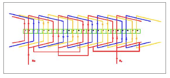
12 12 DC Winding -Design Problem-1 Design and draw Developed simplex armature winding diagram of DC Motor/Generator with 4 Pole, 14 slots, double layer progressive lap winding. Draw the sequence diagram. Show the position of brush & direction of current. Solution: Pole pitch = Number of conductors/pole = 28/4 = 7 We have pole pitch = (Yb + Yf ) / 2 = Yp Hence (Yb + Yf) = 14..(1) (Yb - Yf ) = 2...(2) Solving above equations Yb = 8 and Yf = 6 back pitch yb = 2c/p ± k For lap winding both Yb and Yf must be odd and differ by 2. Satisfying the above condition Yb = 7 and Yf = 5. Winding table Developed Winding Diagram Sequence Diagram

13 13 DC Winding -Design Problem-2 Draw and develop single layer winding for a DC Machine having 32 armature conductors with 4 poles. Mark the poles. Draw the sequence diagram and also show the position of brush & direction of induced current & give equalizer connection. Solution: Winding table Developed Winding Diagram Sequence Diagram
14 14 DC Winding -Design Problem-3 Draw and develop the single layer lap winding diagram of a DC motor having 4 poles, 26 slots with. Mark the poles. Draw the sequence diagram and also show the position of brush & direction of induced current. Solution: Winding table Developed Winding Diagram Sequence Diagram

15 15 DC Winding -Design Problem-4 Draw and develop the double layer lap winding diagram of a DC machine having 6 poles, 18 slots with full pitch. Mark the poles. Draw the sequence diagram and also show the position of brush & direction of induced current. Solution: P=6, No of slots = 18, conductor =36, pole pitch= 36/6=6. YA=YB+YF=12, YB= YF-2 (FOR PROGRESSIVE WINDING) So YB-YF=2; YB=7,YF=5 Winding table Developed Winding Diagram Sequence Diagram
16 16 DC Winding -Design Problem-5 Draw and develop the single layer lap winding diagram of a DC machine having 4 poles, 30 conductors. Mark the poles. Draw the sequence diagram and also show the position of brush & direction of induced current. Solution: P=4, conductor =30, pole pitch= 30/4=7.5 YA = YB+YF =14, YB= YF - 2 (FOR PROGRESSIVE WINDING) So YB-YF=2; YB= 8,YF=6 Winding table Developed Winding Diagram Sequence Diagram
17 17 DC Winding -Design Problem-6 Draw and develop the duplex lap type winding diagram of a DC machine having 4 poles, 32 conductors. Mark the poles. Draw the sequence diagram and also show the position of brush & direction of induced current. Solution: Winding table Developed Winding Diagram


18 18 DC Winding -Design Problem-7 Draw and develop the simplex wave with single layer winding diagram of a DC machine having 4 poles, 42 conductors. Mark the poles. Draw the sequence diagram and also show the position of brush & direction of induced current. Solution: Winding table Developed Winding Diagram Sequence Diagram

19 19 AC Winding -Design Problem-1 Connections: Rs=1 Ys=1+ (120/slot angle)= 1+(120/30)=5 Bs=1+ (240/slot angle)= 1+(240/30)=1+8=9 First pole Second pole Third pole Fourth pole R phase 1,6 7,12 13,18 19,24 B phase 3,8 9,14 15,20 21,2 Y phase 5,10 11,16 17,22 23,4

20 20 AC Winding -Design Problem-2

21 21 AC Winding -Design Problem-3

22 22 AC Winding -Design Problem-4


23 23 AC Winding -Design Problem-5
,14,15 22,23,24 31,32,33 Y phase 7(s),8,9 16,17,18 25,26,27")
24 24 AC Winding -Design Problem-6 Winding table First pole Second pole Third pole Fourth pole R phase 1(s),2,3 10,11,12 19,20,21 28,29,30 B phase 4,5,6 13(s),14,15 22,23,24 31,32,33 Y phase 7(s),8,9 16,17,18 25,26,27 34,35,36
25 25 AC Winding -Design Problem-7 Winding table First pole Second pole Third pole Fourth pole R phase 1+3=4' 4+3=7' 7+3=10' 10+3=1' B phase 2+3=5' 5+3=8' 8+3=11' 11+3=2' Y phase 3+3=6' 6+3=9' 9+3=12' 12+3=3'

,22+6=28'(4') Y phase 5+6=11',6+6=12' 11+6=17',12+6=18' 17+6=23',18+6=24'")
26 26 AC Winding -Design Problem-8 Winding table First pole Second pole Third pole Fourth pole R phase 1+6=7',2+6=8' 7+6=13',8+6=14' 13+6=19',14+6=20' 19+6=25'(1'),20+6=26'(2') B phase 3+6=9',4+6=10' 9+6=15',10+6=16' 15+6=21',16+6=22' 21+6=27'(3'),22+6=28'(4') Y phase 5+6=11',6+6=12' 11+6=17',12+6=18' 17+6=23',18+6=24' 23+6=29'(5'),24+6=30'(6')
27 27 AC Winding -Design Problem-9 Draw the developed winding diagram of an AC machine with the following details: Speed= 3000rpm, No.of slots=24, frequency =50Hz, phase=3, short pitch by 5/6 th pitch, double layer lap & Y connected. Solu: P=120f/N =(120x50)/3000=2, Pole pitch=24/2=12,no of slots/pole/phase=24/2/3=4 Slot angle=180/12=15 0, Coil span=180x5/6=150 0.= 10. Rs=1, Ys=1+120/15=9, Bs=1+240/15=17 Winding table First pole Second pole R phase 1+10=11',2+10=12',3+10=4',4+10=14' 13+10=23',14+10=24',15+10=25'(1'),16+10=26'(2') B phase 5+10=15',6+10=16',7+10=17',8+10=18' 17+10=27'(3'),18+10=28'(4'),19+10=29'(5'),20+10=30'(6') Y phase 9+10=19',10+10=10',11+10=21',12+10=22' 21+10=31'(7'),22+10=32'(8'),23+10=33'(9'),24+10=34'(10') Assignment: Draw the developed winding diagram:

28 28 AC Winding -Design Problem-10
29 29 AC Winding -Design Problem-11 Draw and develop the half coiled single layered concentric winding diagram of a 3 phase, 4 poles with 24 slots and 60 0 phase spread.
30 30 AC Winding -Design Problem-12 Draw and develop the whole coiled single layer concentric winding diagram of a 3 phase, 4 poles with 24 slots and 60 0 phase spread. Solution:
31 31 Single line diagram of substation-design Problem-1 Draw single line diagram with two incoming feeder,110kv, 6 outgoing lines,11kv,2 double bus bar- 110kV,11kV, one auxiliary transformer -5MVA,11kV/415V 3 phase, wave trap coupling condensers, earth switch, OCBs, CT,PT

32 32 Single line diagram of substation-design Problem-2
33 33 Single line diagram of substation-design Problem-3
34 34 Single line diagram of substation-design Problem-4
35 35 Single line diagram of substation-design Problem-5
36 36 Single line diagram of substation-design Problem-6
37 37 References: [1] CAD for Electrical Engineers by M.S Indira, V.D. Sankaralal and D.Beula. [2] A.K.Sawhney,"A course in Electrical Machine Design", Dhanpat Rai & sons,1997. [3]Cheryl R.Shrock,"AutoCAD Pocket Reference ",BPB Publications [4] Open Education Resource: Flipping the classroom with MOODLE : "Example by IDP in Educational Technology, IIT Bombay"
Basic 2D drawing skills in AutoCAD 2017
 Basic 2D drawing skills in AutoCAD 2017 This Tutorial is going to teach you the basic functions of AutoCAD and make you more efficient with the program. Follow all the steps so you can learn all the skills.
1: INTRODUCTION TO AUTOCAD
 AutoCAD syllabus 1: INTRODUCTION TO AUTOCAD Starting AutoCAD AutoCAD Screen Components Drawing Area Command Window Navigation bar Status bar Invoking Commands in AutoCAD Keyboard Ribbon Application Menu
COMPUTER AIDED ELECTRICAL DRAWING (CAED) 10EE65
 10EE65") COMPUTER AIDED ELECTRICAL DRAWING (CAED) 0EE65 Winding Diagrams: (i) DC Winding diagrams (ii) AC Winding Diagrams Terminologies used in winding diagrams: Conductor: An individual piece of wire placed in
COMPUTER AIDED ELECTRICAL DRAWING (CAED) 0EE65 Winding Diagrams: (i) DC Winding diagrams (ii) AC Winding Diagrams Terminologies used in winding diagrams: Conductor: An individual piece of wire placed in
COMPUTER AIDED DRAFTING LAB (333) SMESTER 4
 SMESTER 4") COMPUTER AIDED DRAFTING LAB (333) SMESTER 4 Introduction to Computer Aided Drafting: The method of preparing engineering drawing by using the computer software is known as Computer Aided Drafting (CAD).
COMPUTER AIDED DRAFTING LAB (333) SMESTER 4 Introduction to Computer Aided Drafting: The method of preparing engineering drawing by using the computer software is known as Computer Aided Drafting (CAD).
ARC By default AutoCAD will draw an ARC through three selected points. Options can be set at the start and within the command.
 DFTG 1309 Final Review Notes I. Draw commands: LINE (draws a series of lines) Valid input: Pick button Cartesian coordinates Absolute (2,3) Relative rectangular (@2,3) Relative polar (@ 2
Isometric Drawings. Figure A 1
 A Isometric Drawings ISOMETRIC BASICS Isometric drawings are a means of drawing an object in picture form for better clarifying the object s appearance. These types of drawings resemble a picture of an
06/17/02 Page 1 of 12
 Understanding the Graphical User Interface When you start AutoCAD, the AutoCAD window opens. The window is your design work space. It contains elements that you use to create your designs and to receive
Dharmapuri LAB MANUAL. : B.E. - Civil Engineering Year & Semester : I Year / II Semester
 Dharmapuri 636 703 LAB MANUAL Regulation : 2013 Branch : B.E. - Civil Engineering Year & Semester : I Year / II Semester CE6261-COMPUTER AIDED DRAFTING AND MODELLING LABORATORY ICAL ENG VVIT DEPARTMENT
Dean Muccio AutoCAD Interior Designer. for the. AutoCAD for Mac and PC SDC. Better Textbooks. Lower Prices.
 Dean Muccio AutoCAD 2020 for the Interior Designer AutoCAD for Mac and PC SDC P U B L I C AT I O N S Better Textbooks. Lower Prices. www.sdcpublications.com Powered by TCPDF (www.tcpdf.org) Visit the following
Dean Muccio. AutoCAD 2018 for the. Interior Designer. AutoCAD for Mac and PC SDC. Better Textbooks. Lower Prices.
 Dean Muccio AutoCAD 2018 for the Interior Designer AutoCAD for Mac and PC SDC P U B L I C AT I O N S Better Textbooks. Lower Prices. www.sdcpublications.com Powered by TCPDF (www.tcpdf.org) Visit the following
COURSE: INTRODUCTION TO CAD GRADES: UNIT: Measurement
 UNIT: Measurement - Students will demonstrate correctness in measuring using various scales and instruments. Demonstrate the various marks that make up a ruler including 1/16, 1/8, ¼ and ½. Assessment
Chapter 7 Isometric Drawings
 Chapter 7 Isometric Drawings In this assignment, we are going to look at creating isometric drawings with AutoCAD. These drawing appear to be three dimensional but they are not. An AutoCAD isometric drawing
IN-CLASS DEMONSTRATION. Introduction to AutoCAD 2011 and 2-Dimensional Drawing
 IN-CLASS DEMONSTRATION Introduction to AutoCAD 2011 and 2-Dimensional Drawing GISC, UNIVERSITY OF CALIFORNIA BERKELEY LABORATORY GOALS In this module you will be introduced to the AutoCAD 2011 interface
Chapter 5 Sectional Views
 Chapter 5 Sectional Views There are a number of different types of sectional views that can be drawn. A few of the more common ones are: full sections, half sections, broken sections, rotated or revolved
Unit 2. Single Line Diagram of Substations
 Unit 2 Single Line Diagram of Substations Substations Electric power is produced at the power generating stations, which are generally located far away from the load centers. High voltage transmission
Tutorial 2: Setting up the Drawing Environment
 Drawing size With AutoCAD all drawings are done to FULL SCALE. The drawing limits will depend on the size of the items being drawn. For example if our drawing is the plan of a floor 23.8m X 15m then we
Fundamentals III CHAPTER PROJECT EXERCISE
 CHAPTER 4 Fundamentals III PROJECT EXERCISE This project exercise provides point-by-point instructions for setting up the drawing with layers and then creating the objects shown in Figure P4 1. FIGURE
SPRINGFIELD TECHNICAL COMMUNITY COLLEGE ACADEMIC AFFAIRS
 SPRINGFIELD TECHNICAL COMMUNITY COLLEGE ACADEMIC AFFAIRS Course Number: ARBT 125 Department: Architecture and Building Technology Course Title: Architectural CAD I Semester: Fall Year: 2013 Objectives/
Drawing a Living Room and Family Room Floorplan
 Appendix C Drawing a Living Room and Family Room Floorplan In this chapter, you will learn the following to World Class standards: Draw a Living Room and Family Room Floorplan Draw the Walls and Stairs
Lesson 6 2D Sketch Panel Tools
 Lesson 6 2D Sketch Panel Tools Inventor s Sketch Tool Bar contains tools for creating the basic geometry to create features and parts. On the surface, the Geometry tools look fairly standard: line, circle,
Drawing with precision
 Drawing with precision Welcome to Corel DESIGNER, a comprehensive vector-based drawing application for creating technical graphics. Precision is essential in creating technical graphics. This tutorial
Introduction to AutoCAD 2010
 Page 1 Introduction to AutoCAD 2010 Alf Yarwood Chapter 5 Exercise 1 1. Open AutoCAD 2010 with a double-click on its shortcut icon in the Windows desktop. 2. Call the Polyline tool, either by entering
Object Snap, Geometric Constructions and Multiview Drawings
 Object Snap, Geometric Constructions and Multiview Drawings Sacramento City College EDT 310 EDT 310 - Chapter 6 Object Snap, Geometric Constructions and Multiview Drawings 1 Objectives Use OSNAP to create
Digital Camera Exercise
 Commands Used New Part This lesson includes Sketching, Extruded Boss/Base, Extruded Cut, Fillet, Chamfer and Text. Click File, New on the standard toolbar. Select Part from the New SolidWorks Document
COMPUTER AIDED ENGINEERING DRAWING
 FIRST SEMESTER COMPUTER AIDED ENGINEERING DRAWING COMPUTER SIMULATION LAB DEPARTMENT OF ELECTRICAL ENGINEERING Prepared By: Checked By: Approved By: Engr. Sidra Jhangir Engr. M.Nasim Khan Dr.Noman Jafri
Principles and Practice
 Principles and Practice An Integrated Approach to Engineering Graphics and AutoCAD 2011 Randy H. Shih Oregon Institute of Technology SDC PUBLICATIONS www.sdcpublications.com Schroff Development Corporation
CAD Orientation (Mechanical and Architectural CAD)
") Design and Drafting Description This is an introductory computer aided design (CAD) activity designed to give students the foundational skills required to complete future lessons. Students will learn all
Design and Drafting Description This is an introductory computer aided design (CAD) activity designed to give students the foundational skills required to complete future lessons. Students will learn all
ENGINEERING GRAPHICS ESSENTIALS
 ENGINEERING GRAPHICS ESSENTIALS with AutoCAD 2012 Instruction Introduction to AutoCAD Engineering Graphics Principles Hand Sketching Text and Independent Learning CD Independent Learning CD: A Comprehensive
1.6.7 Add Arc Length Dimension Modify Dimension Value Check the Sketch Curve Connectivity
 Contents 2D Sketch... 1 1.1 2D Sketch Introduction... 1 1.1.1 2D Sketch... 1 1.1.2 Basic Setting of 2D Sketch... 2 1.1.3 Exit 2D Sketch... 4 1.2 Draw Common Geometry... 5 2.2.1 Points... 5 2.2.2 Lines
Appendix B: Autocad Booklet YR 9 REFERENCE BOOKLET ORTHOGRAPHIC PROJECTION
 Appendix B: Autocad Booklet YR 9 REFERENCE BOOKLET ORTHOGRAPHIC PROJECTION To load Autocad: AUTOCAD 2000 S DRAWING SCREEN Click the start button Click on Programs Click on technology Click Autocad 2000
Fundamentals III PROJECT EXERCISE
 4 Fundamentals III PROJECT EXERCISE This project exercise provides point-by-point instructions for setting up the drawing with layers and then creating the objects shown in Figure P4 1. project EXERCISE
Architecture 2012 Fundamentals
 Autodesk Revit Architecture 2012 Fundamentals Supplemental Files SDC PUBLICATIONS Schroff Development Corporation Better Textbooks. Lower Prices. www.sdcpublications.com Tutorial files on enclosed CD Visit
Completed project drawing (dimensions added for reference)
") CHAPTER 5 Fundamentals IV PROJECT EXERCISE This project exercise provides point-by-point instructions for setting up the drawing with layers and then creating the objects shown in the accompanying figure.
CHAPTER 5 Fundamentals IV PROJECT EXERCISE This project exercise provides point-by-point instructions for setting up the drawing with layers and then creating the objects shown in the accompanying figure.
Government of Karnataka Department of Technical Education Board of Technical Examinations, Bengaluru
 Government of Karnataka Department of Technical Education Board of Technical Examinations, Bengaluru Course Title :COMPUTER AIDED Course Code : 15EE47P ELECTRICAL DRAFTING Semester : IV Course Group :
AutoCAD LT 2012 Tutorial. Randy H. Shih Oregon Institute of Technology SDC PUBLICATIONS. Schroff Development Corporation
 AutoCAD LT 2012 Tutorial Randy H. Shih Oregon Institute of Technology SDC PUBLICATIONS www.sdcpublications.com Schroff Development Corporation AutoCAD LT 2012 Tutorial 1-1 Lesson 1 Geometric Construction
Parametric Drawing Using Constraints
 CHAPTER 10 Parametric Drawing Using Constraints PROJECT EXERCISE This project exercise provides point-by-point instructions for creating the objects shown in Figure P10 1. In this exercise, you will apply
Arranging and Patterning Objects
 C H A P T E R Arranging and Patterning Objects Learning Objectives After completing this chapter, you will be able to do the following: Relocate objects using the MOVE tool. Change the angular positions
SDC. AutoCAD LT 2007 Tutorial. Randy H. Shih. Schroff Development Corporation Oregon Institute of Technology
 AutoCAD LT 2007 Tutorial Randy H. Shih Oregon Institute of Technology SDC PUBLICATIONS Schroff Development Corporation www.schroff.com www.schroff-europe.com AutoCAD LT 2007 Tutorial 1-1 Lesson 1 Geometric
Evaluation Chapter by CADArtifex
 The premium provider of learning products and solutions www.cadartifex.com EVALUATION CHAPTER 2 Drawing Sketches with SOLIDWORKS In this chapter: Invoking the Part Modeling Environment Invoking the Sketching
Dimensioning the Rectangular Problem
 C h a p t e r 3 Dimensioning the Rectangular Problem In this chapter, you will learn the following to World Class standards: 1. Creating new layers in an AutoCAD drawing 2. Placing Centerlines on the drawing
Making a Drawing Template
 C h a p t e r 8 Addendum: Metric Making a Drawing Template In this chapter, you will learn the following to World Class standards: 1. Starting from Scratch 2. Creating New Layers in an progecad Drawing
Block References and Attributes
 CHAPTER 11 Block References and Attributes PROJECT EXERCISE 11A This project exercise provides point-by-point instructions for creating the objects shown in Figure P11A 1. In this exercise, you will apply
with MultiMedia CD Randy H. Shih Jack Zecher SDC PUBLICATIONS Schroff Development Corporation
 with MultiMedia CD Randy H. Shih Jack Zecher SDC PUBLICATIONS Schroff Development Corporation WWW.SCHROFF.COM Lesson 1 Geometric Construction Basics AutoCAD LT 2002 Tutorial 1-1 1-2 AutoCAD LT 2002 Tutorial
AutoCAD Civil 3D 2009 ESSENTIALS
 AutoCAD Civil 3D 2009 ESSENTIALS SDC PUBLICATIONS Schroff Development Corporation www.schroff.com Better Textbooks. Lower Prices. Alignments and Profiles Section 2: Profiles In this section you learn how
AutoCAD Tutorial First Level. 2D Fundamentals. Randy H. Shih SDC. Better Textbooks. Lower Prices.
 AutoCAD 2018 Tutorial First Level 2D Fundamentals Randy H. Shih SDC PUBLICATIONS Better Textbooks. Lower Prices. www.sdcpublications.com Powered by TCPDF (www.tcpdf.org) Visit the following websites to
Making an Architectural Drawing Template
 C h a p t e r 8 Addendum: Architectural Making an Architectural Drawing Template In this chapter, you will learn the following to World Class standards:! Starting from Scratch for the Last time! Creating
SolidWorks Part I - Basic Tools SDC. Includes. Parts, Assemblies and Drawings. Paul Tran CSWE, CSWI
 SolidWorks 2015 Part I - Basic Tools Includes CSWA Preparation Material Parts, Assemblies and Drawings Paul Tran CSWE, CSWI SDC PUBLICATIONS Better Textbooks. Lower Prices. www.sdcpublications.com Powered
LABORATORY MANUAL COMPUTER AIDED DESIGN LAB ME-211-F
 LABORATORY MANUAL COMPUTER AIDED DESIGN LAB ME-211-F List of Experiments:- Sl. No. Name of experiment Date Signature 01 02 Setting up of drawing environment by setting drawing limits, drawing units, naming
After completing this lesson, you will be able to:
 LEARNING OBJECTIVES After completing this lesson, you will be able to: 1. Create a Circle using 6 different methods. 2. Create a Rectangle with width, chamfers, fillets and rotation. 3. Set Grids and Increment
Drawing 8e CAD#11: View Tutorial 8e: Circles, Arcs, Ellipses, Rotate, Explode, & More Dimensions Objective: Design a wing of the Guggenheim Museum.
 Page 1 of 6 Introduction The drawing used for this tutorial comes from Clark R. and M.Pause, "Precedents in Architecture", VNR 1985, page 135. Stephen Peter of the University of South Wales developed the
Revit Structure 2013 Basics
 Revit Structure 2013 Basics Framing and Documentation Elise Moss Supplemental Files SDC P U B L I C AT I O N S Schroff Development Corporation Better Textbooks. Lower Prices. www.sdcpublications.com Tutorial
GstarCAD Mechanical 2015 Help
 1 Chapter 1 GstarCAD Mechanical 2015 Introduction Abstract GstarCAD Mechanical 2015 drafting/design software, covers all fields of mechanical design. It supplies the latest standard parts library, symbols
Starting a New Drawing with a Title Block and Border
 Starting a New Drawing with a Title Block and Border From the File menu select New. Within the New file menu toggle the option Drawing, name the file and turn Off the toggle Use Default Template. Select
Relative Coordinates
 AutoCAD Essentials Most drawings are created using relative coordinates. This means that the next point is set from the last point drawn. The last point drawn is stored as temporary 0,0". AutoCAD uses
AutoCAD LT 2009 Tutorial
 AutoCAD LT 2009 Tutorial Randy H. Shih Oregon Institute of Technology SDC PUBLICATIONS Schroff Development Corporation www.schroff.com Better Textbooks. Lower Prices. AutoCAD LT 2009 Tutorial 1-1 Lesson
A Practical Guide to AutoCAD 2019
 A Practical Guide to AutoCAD 2019 Tracy Chadwick and Rick Ellis Foreword written by Lynn Allen A CADapult Press Publication Copyright Copyright CADapult Press, Inc. 2018 All rights reserved. No part of
Chapter 2. Drawing Sketches for Solid Models. Learning Objectives
 Chapter 2 Drawing Sketches for Solid Models Learning Objectives After completing this chapter, you will be able to: Start a new template file to draw sketches. Set up the sketching environment. Use various
Assignment 5 CAD Mechanical Part 1
 Assignment 5 CAD Mechanical Part 1 Objectives In this assignment you will apply polyline, offset, copy, move, and rotated dimension commands, as well as skills learned in earlier assignments. Getting Started
80 ` AutoCAD 2D I. Module 11. Object Snap PREPARED BY. IAT Curriculum Unit. February 2011
 80 ` AutoCAD 2D I Object Snap PREPARED BY IAT Curriculum Unit February 2011 Institute of Applied Technology, 2011 Auto CAD Self-paced Learning Modules AutoCAD 2D Object Snap Learning Outcomes: When you
Engineering & Computer Graphics Workbook Using SolidWorks 2014
 Engineering & Computer Graphics Workbook Using SolidWorks 2014 Ronald E. Barr Thomas J. Krueger Davor Juricic SDC PUBLICATIONS Better Textbooks. Lower Prices. www.sdcpublications.com Powered by TCPDF (www.tcpdf.org)
Autocad Basics 7/28/2009. Chapter 14 - Learning Objectives
 Chapter 14 - Learning Objectives Autocad Basics Chapter 14 July 28, 2009 Use grips to stretch, copy, move, rotate, scale, and mirror objects. Edit objects using the Quick Properties panel and the Properties
Creating a 3D Assembly Drawing
 C h a p t e r 17 Creating a 3D Assembly Drawing In this chapter, you will learn the following to World Class standards: 1. Making your first 3D Assembly Drawing 2. The XREF command 3. Making and Saving
Tutorial Guide to AutoCAD 2014
 Tutorial Guide to AutoCAD 2014 2D Drawing, 3D Modeling Shawna Lockhart SDC P U B L I C AT I O N S For Microsoft Windows Better Textbooks. Lower Prices. www.sdcpublications.com Visit the following websites
Single Line Diagram of Substations
 Single Line Diagram of Substations Substations Electric power is produced at the power generating stations, which are generally located far away from the load centers. High voltage transmission lines are
Assignment 12 CAD Mechanical Part 2
 Assignment 12 CAD Mechanical Part 2 Objectives In this assignment you will learn to apply the hidden lines, isometric snap, and ellipses commands along with commands previously learned.. General Hidden
Engineering & Computer Graphics Workbook Using SOLIDWORKS
 Engineering & Computer Graphics Workbook Using SOLIDWORKS 2017 Ronald E. Barr Thomas J. Krueger Davor Juricic SDC PUBLICATIONS Better Textbooks. Lower Prices. www.sdcpublications.com Powered by TCPDF (www.tcpdf.org)
Tutorial Guide to AutoCAD 2013
 Tutorial Guide to AutoCAD 2013 2D Drawing, 3D Modeling Shawna Lockhart SDC P U B L I C AT I O N S Schroff Development Corporation For Microsoft Windows Better Textbooks. Lower Prices. www.sdcpublications.com
Chapter 6 Title Blocks
 Chapter 6 Title Blocks In previous exercises, every drawing started by creating a number of layers. This is time consuming and unnecessary. In this exercise, we will start a drawing by defining layers
Solid Part Four A Bracket Made by Mirroring
 C h a p t e r 5 Solid Part Four A Bracket Made by Mirroring This chapter will cover the following to World Class standards: Sketch of a Solid Problem Draw a Series of Lines Finish the 2D Sketch Extrude
Isometric Circles and Arcs
 AutoCAD and Its Applications BASICS Supplemental Material Chapter 4 Isometric Circles and Arcs On an isometric drawing, circles appear as ellipses and arcs as elliptical arcs. You must properly align isometric
An Introduction to Autodesk Inventor 2011 and AutoCAD Randy H. Shih SDC PUBLICATIONS. Schroff Development Corporation
 An Introduction to Autodesk Inventor 2011 and AutoCAD 2011 Randy H. Shih SDC PUBLICATIONS www.sdcpublications.com Schroff Development Corporation An Introduction to Autodesk Inventor 2011 and AutoCAD 2011
Tutorial Guide to AutoCAD 2015
 Tutorial Guide to AutoCAD 2015 2D Drawing, 3D Modeling Shawna Lockhart SDC P U B L I C AT I O N S For Microsoft Windows Better Textbooks. Lower Prices. www.sdcpublications.com Powered by TCPDF (www.tcpdf.org)
Unit. Drawing Accurately OVERVIEW OBJECTIVES INTRODUCTION 8-1
 8-1 Unit 8 Drawing Accurately OVERVIEW When you attempt to pick points on the screen, you may have difficulty locating an exact position without some type of help. Typing the point coordinates is one method.
1. Create a 2D sketch 2. Create geometry in a sketch 3. Use constraints to position geometry 4. Use dimensions to set the size of geometry
 2.1: Sketching Many features that you create in Fusion 360 start with a 2D sketch. In order to create intelligent and predictable designs, a good understanding of how to create sketches and how to apply
Symbols and Standards (Architectural CAD)
") Design and Drafting Description In this activity the teacher will give an orientation to the symbols and conventions of Architectural CAD. Industry common symbols are used for most of the fixtures and
Design and Drafting Description In this activity the teacher will give an orientation to the symbols and conventions of Architectural CAD. Industry common symbols are used for most of the fixtures and
SolidWorks 95 User s Guide
 SolidWorks 95 User s Guide Disclaimer: The following User Guide was extracted from SolidWorks 95 Help files and was not originally distributed in this format. All content 1995, SolidWorks Corporation Contents
What s new in IGEMS R9
 General changes and CAD-commands What s new in IGEMS R9 Page 1 General changes and CAD-commands What s new in IGEMS R9 This document is not a complete manual. It describes only the differences between
Principles and Applications of Microfluidic Devices AutoCAD Design Lab - COMSOL import ready
 Principles and Applications of Microfluidic Devices AutoCAD Design Lab - COMSOL import ready Part I. Introduction AutoCAD is a computer drawing package that can allow you to define physical structures
Revit Structure 2012 Basics:
 SUPPLEMENTAL FILES ON CD Revit Structure 2012 Basics: Framing and Documentation Elise Moss autodesk authorized publisher SDC PUBLICATIONS www.sdcpublications.com Schroff Development Corporation Structural
Existing and Design Profiles
 NOTES Module 09 Existing and Design Profiles In this module, you learn how to work with profiles in AutoCAD Civil 3D. You create and modify profiles and profile views, edit profile geometry, and use styles
COMPUTER AIDED DRAFTING (PRACTICAL) INTRODUCTION
 INTRODUCTION") LANDMARK UNIVERSITY, OMU-ARAN LECTURE NOTE: 3 COLLEGE: COLLEGE OF SCIENCE AND ENGINEERING DEPARTMENT: MECHANICAL ENGINEERING PROGRAMME: MCE 511 ENGR. ALIYU, S.J Course title: Computer-Aided Engineering
LANDMARK UNIVERSITY, OMU-ARAN LECTURE NOTE: 3 COLLEGE: COLLEGE OF SCIENCE AND ENGINEERING DEPARTMENT: MECHANICAL ENGINEERING PROGRAMME: MCE 511 ENGR. ALIYU, S.J Course title: Computer-Aided Engineering
Introduction to CATIA V5
 Introduction to CATIA V5 Release 17 (A Hands-On Tutorial Approach) Kirstie Plantenberg University of Detroit Mercy SDC PUBLICATIONS Schroff Development Corporation www.schroff.com Better Textbooks. Lower
AutoCAD LT 2010 Tutorial
 AutoCAD LT 2010 Tutorial Randy H. Shih Oregon Institute of Technology SDC PUBLICATIONS Schroff Development Corporation www.schroff.com Better Textbooks. Lower Prices. AutoCAD LT 2010 Tutorial iii Table
Revit Structure 2014 Basics
 Revit Structure 2014 Basics Framing and Documentation Elise Moss Authorized Author SDC P U B L I C AT I O N S Better Textbooks. Lower Prices. www.sdcpublications.com Powered by TCPDF (www.tcpdf.org) Visit
COURSE OUTLINE. Course Number Course Title Credits DRA190 Introduction to Computer-Aided Drafting 2
 COURSE OUTLINE Course Number Course Title Credits DRA190 Introduction to Computer-Aided Drafting 2 Hours: Co- or Pre-requisite lecture/lab/other 1/2 Catalog description (2009-2011) Catalog Implementation
AutoCAD 2D. Table of Contents. Lesson 1 Getting Started
 AutoCAD 2D Lesson 1 Getting Started Pre-reqs/Technical Skills Basic computer use Expectations Read lesson material Implement steps in software while reading through lesson material Complete quiz on Blackboard
Activity 5.2 Making Sketches in CAD
 Activity 5.2 Making Sketches in CAD Introduction It would be great if computer systems were advanced enough to take a mental image of an object, such as the thought of a sports car, and instantly generate
Applications in Technical Drawing
 Applications in Technical Drawing Objectives: To use drawing aids in orthographic projection. To recognise the use of construction line in orthographic projection. To locate points using OSNAP and OTRACK.
Tutorial 3: Drawing Objects in AutoCAD 2011
 Tutorial 3: Drawing Objects in AutoCAD 2011 Audience: Users new to AutoCAD Prerequisites: None Time to complete: 15 minutes In This Tutorial Please complete the lessons in this tutorial in order. The earlier
SKKK 1021 Engineering Drawing
 SKKK 1021 Engineering Drawing Introduction to AutoCAD Agus Arsad Introduction Overview & background Starting, interface & file system Basic drawing commands Basic editing commands View command Why use
Making an Architectural Drawing Template
 C h a p t e r 8 Addendum: Architectural Making an Architectural Drawing Template In this chapter, you will learn the following to World Class standards: 1. Starting from Scratch 2. Creating New Layers
Lesson 4 Holes and Rounds
 Lesson 4 Holes and Rounds 111 Figure 4.1 Breaker OBJECTIVES Sketch arcs in sections Create a straight hole through a part Complete a Sketched hole Understand the Hole Tool Use Info to extract information
SAULT COLLEGE OF APPLIED ARTS AND TECHNOLOGY SAULT STE. MARIE, ONTARIO COURSE OUTLINE. Introduction to Computers and AutoCAD
 SAULT COLLEGE OF APPLIED ARTS AND TECHNOLOGY SAULT STE. MARIE, ONTARIO COURSE OUTLINE COURSE TITLE: Introduction to Computers and CODE NO. : SEMESTER: 2 PROGRAM: AUTHOR: Civil Engineering Technician Construction
Copyrighted. Material. Copyrighted. Material. Copyrighted. Copyrighted. Material
 Engineering Graphics FREEHAND SKETCHING Introduction to Freehand Sketching Sketching is a very important technique for technical communication. Sketches can transfer ideas, instructions and information
1. Open the Feature Modeling demo part file on the EEIC website. Ask student about which constraints needed to Fully Define.
 BLUE boxed notes are intended as aids to the lecturer RED boxed notes are comments that the lecturer could make Control + Click HERE to view enlarged IMAGE and Construction Strategy he following set of
Introduction to IntelliCAD 6
 Introduction to IntelliCAD 6 These notes explain the basic concepts and techniques for doing 2D line drawings, with dimensions, arranged onto sheets for printing, using the 6.4 or 6.6 versions of IntelliCAD
New Sketch Editing/Adding
 New Sketch Editing/Adding 1. 2. 3. 4. 5. 6. 1. This button will bring the entire sketch to view in the window, which is the Default display. This is used to return to a view of the entire sketch after
Part Design Fundamentals
 Part Design Fundamentals 1 Course Presentation Objectives of the course In this course you will learn basic methods to create and modify solids features and parts Targeted audience New CATIA V5 Users 1