Kits and Parts dot Com Supplying Toroids, Electronic Parts and Kits to Engineers, Schools and Hobbyists
|
|
|
- Jerome O’Connor’
- 5 years ago
- Views:
Transcription
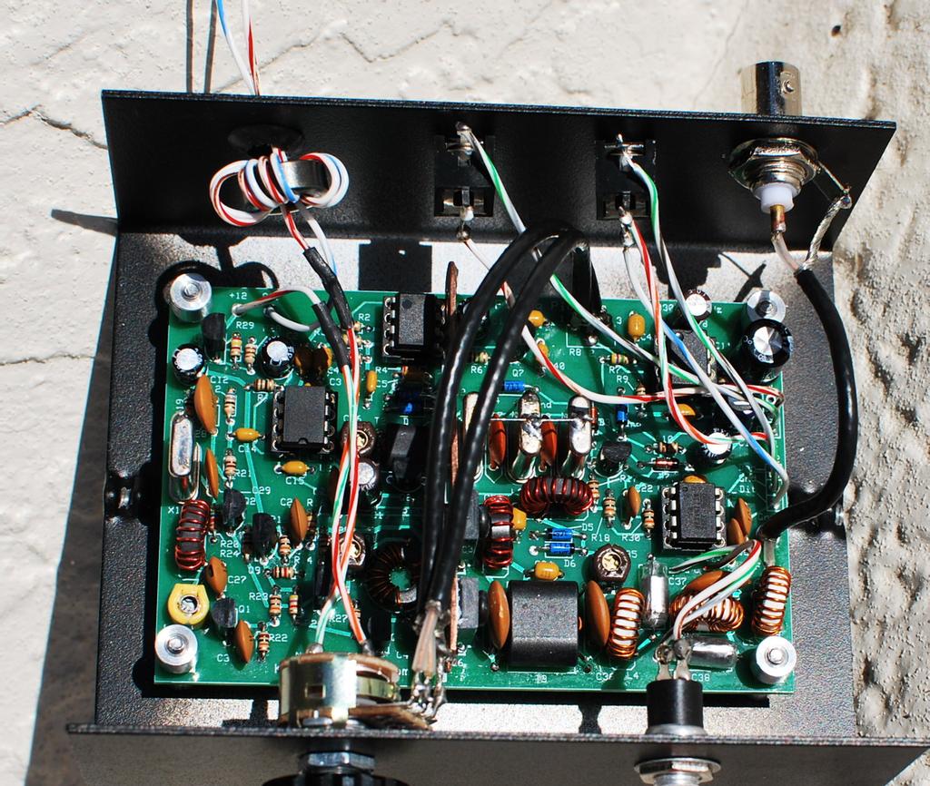
1 Kits and Parts dot Com Supplying Toroids, Electronic Parts and Kits to Engineers, Schools and Hobbyists Home Capacitors PA3AKE Filters W3NQN Filters WA2EBY ToroidKit Inductors MagnetWire Information Parts RFtoolkits * Shopping * Toroids Potluck Circuits Retired Kits Forum Surplus Last Updated Fri, 04 Jan :34: All updates are in the Addendum Section Build this 5 Watt Single Frequency Transceiver for $40 Full 5 Watts output (7,030.7 KHz) using 13.6 VDC Full QSK, one Sideband only, Single Conversion Design Includes built in keyer IC PDF Instructions in (Spanish) [886K] submitted of Jon, EA2SN The purpose of this new transceiver is to... "Provide a high quality, inexpensive transceiver that encourages special groups of hams to communicate with minimal effort." This transceiver was designed for Radio Clubs and/or Special Events. You turn the radio on...you listen...you do not tune...you do not switch anything...you do not search. If you hear someone on "your special frequency", there is a good chance it could be a member of your group. The size of the PCB is only 2.5" (63,5 mm) by 3.8" (96,5 mm), and Yes...it does produce a full 4.99 watts RF out and it is as sensitive as just about anything else that you may have in your radio shack. Custom club/group frequencies are available for 40 meters. The name of this radio shall henceforth be labeled "The Flying Pig Rig".
2

3 Building Instructions: 1. Inventory all Parts. Parts List Read the below section before you start building. If you are missing any parts, contact me immediately. I and will ship the parts the same day. This kit includes all electrical parts to create a functioning transceiver, including 2 phone jacks, a bnc jack, a push-button, volume/on-off switch, magnet wire, heat sink mounting screws and nuts. This kit uses four (4) all black ferrite toroids. One (1) FT37-43 and three (3) FT37-61 toroids; they look the same. The FT37-43 is included in the bag with the very small binocular ferrite and 34 ga wire The 5R1 (5.1) ohm power resistor is used to install and support the heat sink Install the parts in the order show to prevent mechanical installation problems down the line Each PigRig is provided with a Serial Number, attached to the bag holding the PCB and 26 ga wire Attach the label to the rear of your PigRig enclosure or wherever suitable The Serial Number may later be used for tracking in Worked All PigRigs contests :) This kit requires the following items to complete the kit: hook-up wire to connect the controls to the printed circuit board (PCB) Heat sink compound for the RF Finals (Radio Shack Catalog #: ) Flat head hammer or similar tool to fabricate the heat sink 1/8th inch drill bit and a drill to create mounting holes for the heat sink


4 Any Addendums will be listed by date at the end of this document 2. Install all 1/8 Watt Resistors. You will need a magnifying device to verify the resistor color codes. Be careful not to mix up the one 1K and the nine 10K resistors. Bend the resistor leads a sharp 90 degrees from the body of the resistors. The volume control R8 is installed last. Save 3 cut resistor leads for use later to ground the crystal cases. R14: 1K Brown-Black-Red-Gold R10,15,17,18,19,22,23,27,30: 10K Brown-Black-Orange-Gold R6: 1M Brown-Black-Green-Gold R1,9,11: 10 Brown-Black-Black-Gold R2,3,16,26: 4K7 Yellow-Violet-Red-Gold R7: 4M7 Yellow-Violet-Green-Gold R13: 1K2 Brown-Red-Red-Gold R20: 5K6 Green-Blue-Red-Gold R4,5: 220K Red-Red-Yellow-Gold R29: 240 Red-Yellow-Brown-Gold R25: 27 Red-Violet-Black-Gold R12,24: 68 Blue-Gray-Black-Gold R21,28: 910 White-Brown-Brown-Gold 3. Prepare inductor L2. Remove the round toroid from the packet that contains the 1/4 inch binocular ferrite L2: Wind 11 turns of 26 GA red magnet wire on an FT37-43 ferrite toroid, evenly spaced. Cut 12 inches of 26 GA wire. Wind the wire on the toroid clockwise. Trim the wires of L2 to a half inch each. Strip the insulation to the base of the toroid using a hot solder pencil This part will be installed later. 4. Install transformer T2. T2 xfmr is a BN binocular core threaded with fine 34 GA magnet wire. Cut 10 inches (25 cm) of 34 GA red magnet wire and fold the wire in half. Using needlenose pliers, grip the wire at the fold and tightly twist from the folded end for about 1/3 inch (1 cm), about 5 or 6 tight twists Tin the twisted part of the wire using solder and hot solder pencil. The plastic insulation will melt and the solder will tin the wire after applying heat and solder for about seconds. Move the solder pencil back and forth to generate a little friction on the wire.

 of 34 GA red magnet wire and fold the wire in half.")


5 Insert the wire ends thru the binocular holes Insert each wire end thru the opposite hole Repeat 6 more times for a total of 8 full turns. A full turn is defined as a wire going thru both holes of the binocular. Trim the wire ends to about 1/2 inch and tin with solder. Cut 10 inches (25 cm) of 34 GA red magnet wire and fold the wire in half. Insert the wire ends thru the binocular holes as pictured Insert each wire end thru the opposite hole and tighten the turns This creates two full turns. Cut to 1/2 inch each and tin. This is what T2 should look like. Insert T2 into the top of PCB and solder on the bottom, trimming excess leads. 5. Install transformer T1. This xfmr is an FT37-61 toroid with 10 turns primary and 2 turns secondary, centertapped. Cut 8 inches (20 cm) of red 26 GA magnet wire and tightly wind 10 turns on the toroid. Wind T1 toroid in a clockwise direction - Generic Toroid Winding Example Prepare the toroid wires for soldering
, about 5 or 6 tight twists Tin the twisted part of the wire using solder and hot")
 Insert on of the free wire ends thru the toroid as shown.")

6 Cut 4 inches (10 cm) of red 26 GA magnet wire and fold the wire in half. Using needlenose pliers, grip the wire at the fold and tightly twist from the folded end for about 1/3 inch (1 cm), about 5 or 6 tight twists Tin the twisted part of the wire using solder and hot solder pencil. Using solder and a solder pencil, tin 1/2 inch of each wire, about 1/2 inch away from the twist junction. Install the wire by inserting the twisted end into the PCB as shown. Solder and trim. The insert location is immediately to the left of the Q5 label on the PCB (center tap hole) Insert on of the free wire ends thru the toroid as shown. Insert the 10 turn wires into their installation holes, leaving about 1 inch slack above the PCB. Bring the wire that is protruding thru the top of the pcb over and around the toroid and insert the end into the hole above the center tap hole. Bring the other open wire over and down thru the toroid and insert into the hole below the center tap hole. Slowly, tighten the wires and pull the toroid down to the PCB, by alternating pulls on the 4 unsoldered wires. When the toroid is mounted flush on the PCB, solder and clip leads. Make sure that ALL the leads going thru the holes are tinned and ready for soldering. 6. Install transformer T3. This xfmr uses the larger BN binocular, 2 turns primary centertapped and 2 turns secondary. T3 is made just like T2 except for wire length and turns. Cut 5 inches of 26 GA wire and create a 2 turns primary centertapped. Cut 4 inches of 26 GA wire and create a 2 turns secondary. Install into the PCB, tighten all wires, solder and trim leads. 7. Install all ICs and one IC socket. A socket is included for the Keyer Chip Only. You may optionally provide your own sockets for the other ICs but that is not be necessary nor is it required It is possible to reprogram/replace the keyer chip in the future
7 U5: LM317L voltage regulator; note orientation on the PCB U4: Install the 8 pin machine socket at U4 with the notch pointing up towards C23 U4: Insert the ATmel ATtiny keyer chip into U4 socket, the dot positioned towards C23 U1: NE5534AP with the dot pointing to the upper edge of the PCB U2: NE602A with the dot pointing to the LOWER edge of the PCB towards C16 U3: LM-386N-4 with the dot pointing to the upper edge of the PCB 8. Install all Diodes. D3,7: 1N4148 red glass diodes D1,2,4,5,6,8: 1N5711 blue glass diodes 9. Install all Crystals and 2 capacitors. When installing the crystals, tilt the crystals while soldering This will raise the crystal a small bit above the PCB and will prevent trace shorts to the case of the crystal X1: 7031 crystal with a black mark on one side X2,3,4: 7031 without the black mark (highly matched and quality checked) C17,18: 470p (471J) orange disk cap; install between the crystals. Solder one resistor lead accross the top of all 3 crystals in the filter Solder one resistor lead from the top of X4 to the ground below Solder one resistor lead from the top of X1 to the ground below 10. Install all remaining capacitors. Do not install C32, a 270p cap. It will be installed later. C43 (47n) is under evaluation; may not be required. C2,4,7,9,23,33,34,42: 100n (0.1uF) small yellow caps C3,14,15,40,43: 47n (0.047uF) small yellow caps C26: 40p yellow trimmer cap - flat side into square hole C16,31,35: 60p brown trimmer caps - flat side into square hole C5,6: 220p (221) small yellow caps C28: 220p (221J NPO) dark tan disk cap C1,12,13,41: 33uF black electrolytic - observe polarity C8,19: 10uF black electrolytic - observe polarity C11: 470uF black electrolytic - observe polarity C20,21,30: 10n (103) dark tan disk cap C22: 22p (22J NPO) dark tan disk cap C24,25: 1n (102) dark tan disk cap C27: 12p NPO dark tan disk cap with black dot (added 15 pf option - see addendum 2013 Jan 16) C29: 150p (151J) NPO dark tan disk cap C36,39: 270p (271J) NPO dark tan disk cap (C32 is installed later) C37,38: 680p (680J) clear/silver polystyrene cap C10: 47uF black electrolytic - observe polarity 11. Install all Transistors except the RF power amps Q1,2,8: 2N3904 Q3,9: 2N3906 Q4,10: 2N7000 Q7: J Wind and install all remaining Toroid Inductors except L2. L1: Wind 17 turns of 26 GA red magnet wire on an FT37-61 ferrite toroid, evenly spaced. Cut 11 inches of 26 GA wire. Wind the wire on the toroid clockwise. Trim the wires of L1 to a half inch each.


8 Strip the insulation to the base of the toroid using a hot solder pencil Install into the PCB, pull the leads tight using needle nose pliers, solder and trim You should be able to straighten the toroid to match the outline on the PCB L3: Wind 18 turns of 26 GA red magnet wire on an FT37-61 ferrite toroid, evenly spaced. Cut 11 inches of 26 GA wire. Wind the wire on the toroid clockwise. Trim the wires of L3 to a half inch each. Strip the insulation to the base of the toroid using a hot solder pencil Install into the PCB, pull the leads tight using needle nose pliers, solder and trim You should be able to straighten the toroid to match the outline on the PCB L4,6: Wind 20 turns of 26 GA red magnet wire on an T37-7 white toroid, evenly spaced. Cut 12 inches of 26 GA wire. Wind the wire on the toroid clockwise. Trim the wires of L4,6 to a half inch each. Strip the insulation to the base of the toroid using a hot solder pencil Install into the PCB, pull the leads tight using needle nose pliers, solder and trim You should be able to straighten the toroid to match the outline on the PCB L5: Wind 23 turns of 26 GA red magnet wire on an T37-7 white toroid, evenly spaced. Cut 13 inches of 26 GA wire. Wind the wire on the toroid clockwise. Trim the wires of L5 to a half inch each. Strip the insulation to the base of the toroid using a hot solder pencil Install into the PCB, pull the leads tight using needle nose pliers, solder and trim You should be able to straighten the toroid to match the outline on the PCB 13. Prepare the Copper Heat Sink & Install the RF Final Transistors. This Kit uses a custom pure copper heat sink that will require preparation. Flatten the Copper pipe clamp using your hands, a vise, and a flat head hammer. Hammer it until it is totally flat; may take a few minutes, but Copper is soft. With a pen, mark 2 drill holes exactly 0.5 inch and 1.0 from one end, centered from top/bottom. If you have a punch, punch the copper at the marks for easier drilling accuracy. Drill 2 holes using an 1/8 inch drill bit to accommodate a size 4-40 screw. Deburr the holes using a larger drill bit or other hard tool. The heat sink will extend about 0.15 inches from the lower edge of the PCB If you wish, cut of the excess copper per the picture; file/sand/deburr. Cut one lead from the 5R1 power resistor. Solder to the end of the heat sink per picture This will require quite a bit of heat from your soldering tool


9 Q5,6: BD Loosely mount the RF Finals to the Heat Sink using the nuts and screws provided, Make shure that the part number (BD139-16) is visible, facing to the right, away from the heat sink. Apply a little heat sink grease between the heat sink and the finals. Fully insert the assembly into the Q5 and Q6 labeled locations. If you have an IC socket installed at U1, then the assembly should be raised about 0.2 inches or enough so that the heat sink does not short to pins 5-8 on U1. Solder both transistors and the cut resistor lead, per the patern on the PCB all the time keeping the heat sink parallel to the PCB. L2: Locate the previously prepared toroid with the 11 turns red magnet wire. Install into the PCB, pull the leads tight using needle nose pliers, solder and trim You should be able to straighten the toroid to match the outline on the PCB C32: 270p (271J) NPO dark tan disk cap; install between the finals and T3.
 for the PigRig are from Ten-Tec The TP/TPB/TPC-19 ($7.")
10 14. Connections. BEFORE YOU APPLY POWER TO THE PIGRIG... Make sure your power polarity is correct else you will be replacing ICs and the Finals Recommend chassis/enclosures (Black Color) for the PigRig are from Ten-Tec The TP/TPB/TPC-19 ($7.81) and TP/TPB/TPC-41 ($9.15) are ideal for this project. Connect the 10K volume pot w/switch to R8 via your shielded audio cable Using one shielded cable, connect the inner conductor from R8(2) to pin-3 on the volume control Connect the cable ground shield to R8(3) and pin-2 on the volume control Using a second shielded cable, connect the inner conductor from R8(1) to pin-4 on the volume control Connect the cable ground shield to R8(3) and pin-2 on the volume control


11 Connect a Speaker or Headphones to J1 via one of the 3.5 mm phono connectors Connect an Antenna to J4 via the provided BNC connector or connect your own RF output connector Connect paddles or a straight key to J2 via the other 3.5 mm phono connector Connect the Push Button Switch via 2 wires to the PCB holes below pins 4 and 5 of U4, labeled "G-C" Connect +13V volts (+/- 1 volt) to the holes in the upper left corner of the PCB. If you live near AM broadcast stations, you should install a common mode choke in the 12V power wires. Make a choke using the FT50-75, half inch diameter black toroid with 5 turns of dual 26 gauge wires. Do not let the power supply ground connect directly to any metal box ground The power supply ground must connect to the PCB/chassis through the choke only. A 1/4 inch Rubber Grommet is included to protect power wires running through a chassis/enclosure wall. 15. Transmit Frequency Alignment using a Frequency Counter or a Calibrated Accurate Receiver (CAR) The center frequency of the front end crystal filter (X2,3,4) is 7,030,700 Hz +/- 30 Hz We need to adjust our Transmit Oscillator to that frequency by adjusting the yellow trimmer capacitor C26 on the left side of the PCB Connect a 5 watt or greater 50 ohm dummy load to the antenna connector. Connect a frequency counter to the RF ouput. Apply 10 (ten) Volts DC power...this prevents damage to the finals in case there is an error with the binocular ferrite. Most Freq Ctrs are sensitive enought to measure the RF ouput by connecting the FC probe onto anything metallic on/near the dummy load. if this is not the case, connect the FC directly to the RF output, or through a small coupling capacitor, less than 10 pf. Place the keyer into straight key mode (see below) and key the transmitter; adjust C26 for a frequency of 7,030,700 Hz +/- 10 Hz If you do not have a frequency counter, use a calibrated accurate receiver, setting the receive freq to 7,030.7 KHz Place the keyer into straight key mode and key the transmitter; adjust C26 for an audio freq of 600 Hz +/- 25 Hz coming from your CAR. This completes the transmitter output frequency alignment. The oscillator switches between receive and transmit modes by including the 12 pf capacitor C27 in parallel with C26 when in transmit mode. When C27 is not grounded through transistor Q1, the X1 oscillator frequency is about 600 Hz higher, which provides the receive mode offset frequency. When a received signal is directly in the middle of the bandpass (7,030.7 KHz), you will hear the signal as 600 Hz +/- from the speaker/headphones. 16. Transmit Driver Alignment. Apply 10 (ten) Volts DC power...this prevents damage to the finals in case there is an error with the binocular ferrite. Adjust C31 for maximum transmitter output - should be about 1 Watts using 10 Volts DC If you do not get 1 Watt output, fix the problem before continuing Apply 13.6 Volts DC and Adjust C31 for maximum transmitter output. You can use a wattmeter or SWR meter or receiver to adjust C31 for maximum output. Using 13.6 volts and a 50 ohm dummy load, you should have 5 Watts output (44 volts peak-to-peak on a scope) This completes the transmitter driver alignment. 17. Receiver Alignment using a 7,030.7 KHz signal source. Adjust the input and output tuned circuits connected to the crystal filter (X2,3,4) Connect any antenna to the Pig Rig. Anything from a 2 foot wire up a large antenna. Turn on a signal source in the shack. Either a low power transmitter into a dummy load or a sig-gen. Adjust C16 and C35, back and forth for maximum audio (approx 600 Hz) coming from the speaker/headphones. The lower the signal level from the source, the easier it is to adjust C16 and C35 It is important to note that the signal source be 7,030.7 to optimize the bandpass filter for a narrow bandwidth. This completes the receiver alignment.
12 The Flying Pig Rig Keyer Instructions This is a very basic Keyer (ATmel AVR Assembler Source Code available upon request) On power-up, the keyer defaults to 15 WPM and a sidetone of 625 Hz and annunciates "OO" (without keying the XMTR) The internal timing oscillator in the Keyer Chip is an RC oscillator that runs at 9.6 MHz +/- 10 pct Factory Calibration. Typical accuracy is +/- 5 percent; The accuracy can be impoved to +/- 2 percent if one takes the time to calibrate the oscillator and reprogram the keyer chip. This procedure is too time consuming for 200 chips but may be OK for you. The accuracy is typically +/- 5 pct so your sidetone may be off by +/- 5 pct and your keying WPM may also be off. That means if you set the WPM speed to 20 WPM, you may actually have it set at 19 or 21 WPM; should not be a problem. The keyer is placed into the "Command" mode by pressing and releasing the Cmd Button. The keyer has the following commands available after pressing the Cmd Button: "E" (.) or "T" (-) Toggles between normal keyer and straight key mode, acknowleged by annunciating "R" in CW. "R" (.-.) Toggles between normal and reverse paddles keys, acknowleged by annunciating "R" in CW. "S" (...) Set keyer speed in WPM. Speed is entered as two numerical digits. After sending the "S" command, the keyer sends a DIT (e) as a prompt for the first speed character (0-4) After sending the first speed number, wait for another DIT (e) prompt and send the 2nd number (0-9) Depending upon what you enter, you will hear a "?" for ERROR or an "R" for a "Roger" acknowlegement. Valid keyer speeds are 1 to 45 WPM (good luck trying to send/use 1 WPM) "F" (..-.) Sets the sidetone frequency. After sending the "F" command, the keyer sends a DIT (e) as a prompt for the tone character (0-9) Depending upon what you enter, you will hear a "?" for ERROR or an "R" for a "Roger" acknowlegement. The following table equates the sidetone number with the sidetone frequency: 9 = 357 hz 8 = 385 Hz 7 = 417 Hz 6 = 455 Hz 5 = 500 Hz 4 = 555 Hz 3 = 625 Hz 2 = 714 Hz 1 = 833 Hz 0 = 1000 Hz To Reset the Keyer to the Default mode, hold the Cmd button active until you hear "OO" Then immediately release the Command Button, else you will send another Command request. The PigRig is now finished,... except for your first QSO. See you on 7,030.7 KHz.
13

14 Addendum Section: 2012 Dec 07 - received PCBs from Dec 08 - built first PigRig, serial number '0' 2012 Dec 09 - completed kits for distribution 2012 Dec 09 - modified section 13; optional installed IC socket for U1 and heat sink conflict Dec 09 - added picture of completed pigrig in a tentec box (TP/TPB/TPC-19) 2012 Dec 10 - PigRig starts shipping 2012 Dec 15 - Added Parts List 2012 Dec 15 - If you want to talk about building the kit...my Skype ID is w8diz_ that's with an underscore 2012 Dec 17 - Added instructions for the Keyer Push Button Command Switch in Section Dec 19 - Installation of C43 (47n) is now recommended - slight improvement in transmit output 2012 Dec 20 - Corrected parts list - R13 from 560 ohms (bad) to 1K2 ohms (good) per schematic 2012 Dec 21 - Test transmitter output using 10 Volts DC = 1 Watt RF output before applying 13.6 Volts for full output Dec 22 - Schematic tilted 90 degrees for easier printing for some folks 2012 Dec 27 - Scope Signal Levels Peak-Peak and DC voltages in the Oscillator - Driver RF chain using 14 Volt DC Supply Location Rcve-DC Rcve-Sig Xmit-DC Xmit-Sig U2 Pin6 5.25Vdc 280mVrf 5.24Vdc 280mVrf Q2 Collector 13.5Vdc 1.4Vrf 13.25Vdc 2.0Vrf Q3 Emitter 13.9Vdc 880mVrf 13.4Vdc 1.1Vrf Q3 Collector 14.0Vdc 1.2Vrf.01Vdc 14Vrf 2012 Dec 27 - Variable capacitor settings Maximum Capacitance Midway Capacitance Minimum Capacitance 2012 Dec 29 - All PigRig purchases on or after Dec 29, 2012 include a new keyer chip - see below 2012 Dec 29 - Updated Keyer Docs Keyer Text Document Dec 29, Dec 29 - New Keyer Source Code Keyer Source Code Dec 29, Jan 03 - If you need an alignment tool for the trimmers, look up "GC 8608" - available at newark.com and onlinecomponents.com 2013 Jan 04 - Version 2 of the keyer is available to current PigRig owners for $2(USA), $3(DX) or available free if you mail in your old chip (not recommended) or available free when making any kitsandparts purchase (recommended). Paypal ID for purchases is info5 at kitsandparts dot com 2013 Jan 10 - Bandwidth scan of the 3-crystal front end filter Jan 16 - If you find that your XMIT/RCVE offset is too low, you can increase the offset by replacing C27, the 12 pf cap with a 15 pf cap, added to the bag (01/16/13) with the small binocular core, or you can add one turn to L1 and re-align the xmit freq. End of Addendum Section: top Toroids, Ferrites
Build this Direct Digital Synthesizer "Development Kit" By: Diz Gentzow, W8DIZ
 Build this Direct Digital Synthesizer "Development Kit" By: Diz Gentzow, W8DIZ A great tutorial for adding a keypad to the DDS Kit by Bruce, W8BH This manual has been prepared to be read directly on screen.
Read This Page First
 Read This Page First If you are reading this you know the manuals are always available at QRPKITS.com. This is version 8.0 of the manual dated 4/27/2016. There is no need to print out the whole assembly
Building a Bitx20 Version 3
 Building a Bitx20 Version 3 The board can be broken into sections and then built and tested one section at a time. This will make troubleshooting easier as any problems will be confined to one small section.
Assembly Manual V1R2B-Rev1.0D
 Assembly Manual V1R2B-Rev1.0D for 4 State QRP MagicBox - Solid State Transmit/Receive System Designed by: Jim Kortge, K8IQY Copyright 2009-2012 - All rights reserved This system is the result of some brainstorming
Assembly Instructions for the 1.5 Watt Amplifier Kit
 Assembly Instructions for the 1.5 Watt Amplifier Kit 1.) All of the small parts are attached to a sheet of paper indicating both their value and id. 2.) Leave the parts affixed to the paper until you are
Connecting the FCC-2 to the Hendricks DC Kits Bob Okas, W3CD
 Connecting the FCC-2 to the Hendricks DC Kits Bob Okas, W3CD This is an application note that describes how you can connect the NorCal FCC-1/2 combination to the DC kits. It involves a few extra components
Building the Sawdust Regenerative Receiver
 Building the Sawdust Regenerative Receiver Introduction The Sawdust is a super regenerative receiver using the basic Armstrong design architecture. The receiver uses one toroidal transformer to provide
Building the Sawdust Regenerative Receiver
 Building the Sawdust Regenerative Receiver Introduction The Sawdust is a super regenerative receiver using the basic Armstrong design architecture. The receiver uses one toroidal transformer to provide
KN-Q10 Assembly Manual
 KN-Q10 Assembly Manual Translated by Adam Rong, BD6CR/4 with permission from Ke Shi, BA6BF Edited by Stephen, VK2RH Revision B, Oct 14, 2010 Thank you for purchasing the KN-Q10 4 Band SSB/CW Dual Mode
Hendricks QRP Kits The Twofer Rev
 Hendricks QRP Kits The Twofer Rev 1 11-15-06 1. Description The Twofer is a classic QRP transmitter that s easy to assemble and operate. It uses a JFET VXO (variable crystal oscillator), driver stage and
N3ZI Kits General Coverage Receiver, Assembly & Operations Manual (For Jun 2011 PCB ) Version 3.33, Jan 2012
 Version 3.33, Jan 2012") N3ZI Kits General Coverage Receiver, Assembly & Operations Manual (For Jun 2011 PCB ) Version 3.33, Jan 2012 Thank you for purchasing my general coverage receiver kit. You can use the photo above as a
N3ZI Kits General Coverage Receiver, Assembly & Operations Manual (For Jun 2011 PCB ) Version 3.33, Jan 2012 Thank you for purchasing my general coverage receiver kit. You can use the photo above as a
Assembly Instructions
 Assembly Instructions For the SSQ-2F 3.1 MHz Rife Controller Board Kit v1.41 Manual v1.00 2012 by Ralph Hartwell Spectrotek Services GENERAL ASSEMBLY INSTRUCTIONS Arrange for a clean work surface with
QRPGuys Michigan Mighty Might Plus 40M Transmitter
 QRPGuys Michigan Mighty Might Plus 40M Transmitter First, familiarize yourself with the parts and check for all the components. If a part is missing, please contact us and we will send one. You must use
Assembly Instructions for the FRB FET FM 70 Watt Amp
 Assembly Instructions for the FRB FET FM 70 Watt Amp 1.) Orient the circuit board with the diagram 2.) Use a narrow chisel tip 25-30 watt soldering iron for assembly 3.) All the small parts are taped onto
Pacific Antenna Easy Transmitter Kit
 Pacific Antenna Easy Transmitter Kit Introduction The Easy Transmitter kit from qrpkits.com provides a crystal controlled transmitter with VXO tuning. The circuit consists of a N3904 based crystal oscillator
Easy Transmitter. Support ETX_REV5_Manual V2.7 Revised
 Easy Transmitter Introduction The Easy Transmitter kit from qrpkits.com provides a basic, crystal controlled transmitter with VXO tuning to provide a small tuning range around the crystal frequency. It
HT-1A Dual Band CW QRP Transceiver. Kit Building Instructions
 HT-A Dual Band CW QRP Transceiver Kit Building Instructions Rev B, July 8, 08 Designed by BD4RG Exclusively distributed by CRKITS.COM and its worldwide distributors Join the group http://groups.io/g/crkits
Cricket 80a Assembly Manual v Copyright David Cripe NM0S The 4 State QRP Group
 Cricket 80a Assembly Manual v. 1.0 Copyright 2017 David Cripe NM0S The 4 State QRP Group Introduction Thank you for purchasing a CRICKET 80a Transceiver. We hope you will enjoy building it and find it
Building and Operating: LF Converter An SA612 based LF up-converter from Jackson Harbor Press
 Introduction: Building and Operating: LF Converter An SA612 based LF up-converter from Jackson Harbor Press The frequencies below the broadcast band are covered by few receivers on the market - those that
Pacific Antenna Easy TR Switch
 Pacific Antenna Easy TR Switch Kit Description The Easy TR Switch is an RF sensing circuit with a double pole double throw relay that can be used to automatically switch an antenna between a separate receiver
WA3RNC 30 METER CRYSTALPLEXER TRANSMITTER KIT ASSEMBLY INSTRUCTIONS
 WA3RNC 30 METER CRYSTALPLEXER TRANSMITTER KIT ASSEMBLY INSTRUCTIONS Description The WA3RNC 30 Meter Crystalplexer is a low power crystal controlled QRP transmitter offering a significantly improved tuning
Pacific Antenna - Easy TR Switch
 Pacific Antenna - Easy TR Switch Kit Description The Easy TR Switch is an RF sensing switch that can be used to switch an antenna between a receiver and transmitter. It also has a second switched pair
Read This Page First
 Read This Page First If you are reading this you know the manuals are always available at QRPKITS.com. If you have questions contact qrpkits.com@gmail.com There is no need to print out the whole assembly
Stand Alone VXO (SAVXO) Assembly Manual Manual Version 1.0B_
 Assembly Manual Manual Version 1.0B_") Stand Alone VXO (SAVXO) Assembly Manual Manual Version.0B_0-6-0 Designed by: Jim Kortge, K8IQY Kitted & Sold by: 4 State QRP Group Copyright: 0 Forward Thank you for purchasing a 4 State QRP Group Stand
Stand Alone VXO (SAVXO) Assembly Manual Manual Version.0B_0-6-0 Designed by: Jim Kortge, K8IQY Kitted & Sold by: 4 State QRP Group Copyright: 0 Forward Thank you for purchasing a 4 State QRP Group Stand
Construction Manual 6m-Linear-Transverter XV6/10
 Construction Manual 6m-Linear-Transverter XV6/10 Holger Eckardt DF2FQ Kirchstockacherstr. 33 D-85662 Hohenbrunn 2606 Technical data exciter frequency: 28... 30 MHz RF frequency: 50... 52 MHz supply voltage:
S-Pixie QRP Kit. Student Manual. Revision V 1-0
 S-Pixie QRP Kit Student Manual Revision V 1-0 Introduction The Pixie 2 is a small, versatile radio transceiver that is very popular with QRP (low power) amateur radio operators the world over. It reflects
Building the Toothpick Audio CW Filter
 Building the Toothpick Audio CW Filter Introduction The toothpick is a simple variable bandpass audio filter designed to compliment the Splinter QRPp Trans-Receiver. The filter also contains an audio amplifier
Read This Page First
 Pacific Antenna 0 Watt HF Amplifier Kit Manual This is Version 5.5 dated 060505 Read This Page First If you are reading this you know the manuals are always available at QRPKITS.com. If you have questions
Building and Operating: Son of Zerobeat A PIC based CW zerobeat indicator from Jackson Harbor Press
 Building and Operating: Son of Zerobeat A PIC based CW zerobeat indicator from Jackson Harbor Press Ed Nisley, KE4ZNU, wrote an article published in the August, September and October of 1996 issues of
Penrose Quantizer Assembly Guide
 Penrose Quantizer Assembly Guide Schematic and BOM The schematic can be found here: www.sonic-potions.com/public/penrosequantizerschematic.pdf The BOM is available at google docs: Link to BOM Prepare the
Arizona ScQRPion QRP Club. Ft Tuthill w DC CW Transceiver for 80m Part 1 of 2. by Dan Tayloe, N7VE. Ft Tuthill Page 1 of 31
 Arizona ScQRPion QRP Club Ft Tuthill 80 2.5w DC CW Transceiver for 80m Part 1 of 2 by Dan Tayloe, N7VE Page 1 of 31 Table of Contents Specifications... 4 Specifications... 4 Receiver... 4 Transmitter...
SoftRock v6.0 Builder s Notes. May 22, 2006
 SoftRock v6.0 Builder s Notes May 22, 2006 Be sure to use a grounded tip soldering iron in building the v6.0 SoftRock circuit board. The soldering iron needs to have a small tip, (0.05-0.1 inch diameter),
Ozark Patrol Assembly Manual
 Ozark Patrol Assembly Manual Copyright 2014 David Cripe NM0S The 4 State QRP Group Thank you for purchasing a Ozark Patrol kit. We hope you will enjoy building it and and find it a fun addition to your
Pacific Antenna Field Strength Indicator Kit
 Pacific Antenna Field Strength Indicator Kit Description The Field Strength Indicator kit from Pacific Antenna provides a visual way to monitor the presence and relative strength RF fields through the
Construction Manual 4m-Linear-Transverter XV4-15
 Construction Manual 4m-Linear-Transverter XV4-15 Holger Eckardt DF2FQ Kirchstockacherstr. 33 D-85662 Hohenbrunn 3207 Technical data exciter frequency: 21.0... 21.5 MHz RF frequency: 70.0.. 70.5 MHz supply
HW-8-TR V3 PARTS LIST
 HW-8-TR V3 PARTS LIST Qty Ref Description Markings 4C2 C3 C4 C5 Capacitor Disc.1ls.1uF 104 1 C1 Capacitor Disc.2ls.1uF 100V 104 1 QSKMOD-C92 Capacitor Electrolytic 1uF 50V 1 QSKMOD Capacitor Mylar.47uF
Bill of Materials: General Purpose Alarm, Pulsed PART NO
 General Purpose Alarm, Pulsed PART NO. 2190207 I hate alarms that sound continuously - unless they are smoke alarms. Smoke alarms should be annoying, but others should not. I wanted an alarm for a function
The ROSE 80 CW Transceiver (Part 1 of 3)
") Build a 5 watt, 80 meter QRP CW Transceiver!!! Page 1 of 10 The ROSE 80 CW Transceiver (Part 1 of 3) Build a 5 watt, 80 meter QRP CW Transceiver!!! (Designed by N1HFX) A great deal of interest has been
Build a 5 watt, 80 meter QRP CW Transceiver!!! Page 1 of 10 The ROSE 80 CW Transceiver (Part 1 of 3) Build a 5 watt, 80 meter QRP CW Transceiver!!! (Designed by N1HFX) A great deal of interest has been
Pacific Antenna Simple Keyer Kit
 Pacific Antenna Simple Keyer Kit Specifications and Features: Speed range of 5 to 30 wpm Operates in either iambic A or B mode, with B being the default 2 message memories Tune and Beacon modes Built on
The DCxxB family of transceivers
 The DCxxB family of transceivers High performance Direct Conversion transceivers for 40, 30 and 0 meters. A KDJV Melt Solder design Distributed by Pacific Antenna www.qrpkits.com Join Yahoo's DC40 kits
Foxhunt Offset Attenuator. Parts List:
 When your closing in on the fox you may find the signals to be so strong that you can no longer find a peak or null with your antenna. Sometimes the signal is so strong that the RF will leak straight into
LDB-1 Kit Instructions Page 1 of 8
 LDB-1 Kit Instructions Page 1 of 8 Important Information Congratulations and thank you for your purchase of the LDB-1 Little Drummer Boy Analog Drum Machine Kit! Before you start, please read the enclosed
Pacific Antenna 10 Watt HF Amplifier Kit
 Pacific Antenna 0 Watt HF Amplifier Kit Description Our 0 watt Linear, HF amplifier kit is designed to increase the power output of low power transmitters. Gives up to 5dB gain and includes an input attenuator
Pacific Antenna Low Pass Filter Kit
 Pacific Antenna Low Pass Filter Kit Description Many basic transmitter and/or transceiver designs have minimal filtering on their output and frequently have significant harmonic content in their signals.
CW-ADD. Universal CW Adapter for SSB Transceivers. Assembly manual. Last updated: October 1,
 CW-ADD Universal CW Adapter for SSB Transceivers Assembly manual Last updated: October 1, 2017 ea3gcy@gmail.com Updates and news at: www.ea3gcy.com Thanks for building the Universal CW Adapter kit CW-ADD
Instructions for Building the Pulsed Width Modulation Circuit. MC-12 (DC Motor Controller or PWM) From Electronic Light Inc. (revised kit 10/03/08)
 From Electronic Light Inc. (revised kit 10/03/08)") Instructions for Building the Pulsed Width Modulation Circuit MC-12 (DC Motor Controller or PWM) From Electronic Light Inc. (revised kit 10/03/08) Congratulations on your purchase of the MC-12 DC Motor
Instructions for Building the Pulsed Width Modulation Circuit MC-12 (DC Motor Controller or PWM) From Electronic Light Inc. (revised kit 10/03/08) Congratulations on your purchase of the MC-12 DC Motor
The Walford Electronics Ford Receiver Kit Project Construction Manual
 The Walford Electronics Ford Receiver Kit Project Construction Manual Walford Electronics Ford Receiver construction manual V1.5 Page 1 of 22 Introduction The Ford receiver has four stages: The first stage
DEM Part Number L144-28INTCK 144 MHz Transverter Kit and complete kit
 DEM Part Number L144-28INTCK 144 MHz Transverter Kit and complete kit Power Out: Noise Figure and Gain: DC Power Requirement: 50 mw linear minimum 3.5 db NF nominal, 5 dbg maximum 12-15.5 VDC, 13.8 nominal
Enhancing Your QRP Operating Enjoyment
 QRP-DWM Directional-Coupler Watt Meter Preliminary By: W5USJ CyM-Tech Documentation Services Enhancing Your QRP Operating Enjoyment PCB Assembly Top View Addendum: Correct missing toroid ground after installing
Wiring Manual NEScaf April 2010 (August 2006)
") Wiring Manual NEScaf April 2010 (August 2006) Switched Capacitor Audio Filter The NEScaf is a switched capacitor audio filter (acronym SCAF) built around a building-block type filter chip. The NEScaf will
Wiring Manual NEScaf April 2010 (August 2006) Switched Capacitor Audio Filter The NEScaf is a switched capacitor audio filter (acronym SCAF) built around a building-block type filter chip. The NEScaf will
V6.2 SoftRock Lite Builder s Notes. November 17, 2006
 V6.2 SoftRock Lite Builder s Notes November 17, 2006 Be sure to use a grounded tip soldering iron in building the v6.2 SoftRock circuit board. The soldering iron needs to have a small tip, (0.05-0.1 inch
SoftRock v6.0 Builder s Notes. April 6, 2006
 SoftRock v6.0 Builder s Notes April 6, 006 Be sure to use a grounded tip soldering iron in building the v6.0 SoftRock circuit board. The soldering iron needs to have a small tip, (0.05-0. inch diameter),
BP-1A. Band-Pass variable filter continuous tuning from 3 to 30MHz. For analogue or software-defined receivers (SDR) Assembly manual
 Assembly manual") BP-1A Band-Pass variable filter continuous tuning from 3 to 30MHz. For analogue or software-defined receivers (SDR) Assembly manual Last updated: December 1, 2017 ea3gcy@gmail.com Updates and news at:
BP-1A Band-Pass variable filter continuous tuning from 3 to 30MHz. For analogue or software-defined receivers (SDR) Assembly manual Last updated: December 1, 2017 ea3gcy@gmail.com Updates and news at:
PM124 Installation Instructions. See important note about revisions of this board on the last page.
 Marchand Electronics Inc. PO Box 473, Webster, NY 14580 Tel:(716) 872-0980 Fax:(716) 872-1960 info@marchandelec.com http://www.marchandelec.com (c)1997 Marchand Electronics Inc. PM124 Installation Instructions
LED Field Strength Indicator Kit
 LED Field Strength Indicator Kit Description The Field Strength Indicator kit from Qrpkits.com provides a visual way to monitor RF fields through the brightness of an LED. It will respond to RF fields
Pacific Antenna Easy SWR Indicator Kit
 Pacific Antenna Easy SWR Indicator Kit Description Monitoring the match of an antenna to your transmitter or adjusting an antenna tuner for best match requires an indicator of the reflected power as an
RadiØKit Μ CW HAM RADIO TRANSCEIVER KIT. Assembly and operating manual
 RadiØKit-120 20Μ CW HAM RADIO TRANSCEIVER KIT Assembly and operating manual Boreiou Ipirou 78 Kolonos Athens- Greece - 10444 Tel: 210.5150527 210.5132673 www.freebytes.com Thank you for buying RadiØKit-1,
Step by Step Building PJ meter ARDF Receiver Kit. CRKITS.COM August 5, 2013
 Step by Step Building PJ-80 80-meter ARDF Receiver Kit CRKITS.COM August 5, 2013 What is ARDF? ARDF is the abbreviation of Amateur Radio Direction Finding, or so called Fox Hunting. If you are looking
SoftRock v5.0 Builder s Notes. December 12, Building a QSD Kit
 SoftRock v5.0 Builder s Notes December 12, 2005 Building a QSD Kit Be sure to use a grounded tip soldering iron in building the QSD board. The soldering iron needs to have a small tip, (0.05-0.1 inch diameter),
"Nighthawk" CW Transceiver Kit V3.1
 "Nighthawk" CW Transceiver Kit V3.1 Brief Introduction The "Nighthawk" CW transceiver is based on a well-known US design by Dave Benson, K1SWL at Small Wonder Labs. Its classic design includes a standard
Instruction Manual Cyclone Meter Transceiver. Revision 0 Copyright 2013 David Cripe NM0S & Four State QRP Group
 Instruction Manual Cyclone 40 40 Meter Transceiver Revision 0 Copyright 2013 David Cripe NM0S & Four State QRP Group Introduction Thank you for purchasing a Cyclone 40 transceiver kit. We hope you will
SUPER Tuna ][+ Builder s Guide
![SUPER Tuna ][+ Builder s Guide](/thumbs/72/66369453.jpg "SUPER Tuna ][+ Builder s Guide") SUPER Tuna ][+ Builder s Guide Ver2.3 Rex Harper W1REX 3/25/2015 The first thing you should do is to familiarize yourself with what you are going to build. The previous 3 pages are schematics of the
SUPER Tuna ][+ Builder s Guide Ver2.3 Rex Harper W1REX 3/25/2015 The first thing you should do is to familiarize yourself with what you are going to build. The previous 3 pages are schematics of the
IR add-on module circuit board assembly - Jeffrey La Favre January 27, 2015
 IR add-on module circuit board assembly - Jeffrey La Favre January 27, 2015 1 2 For the main circuits of the line following robot you soldered electronic components on a printed circuit board (PCB). The
Build Your Own Clone Li l Reverb Kit Instructions
 Build Your Own Clone Li l Reverb Kit Instructions Warranty: BYOC, Inc. guarantees that your kit will be complete and that all parts and components will arrive as described, functioning and free of defect.
PM24 Installation Instructions
 Marchand Electronics Inc. PO Box 473, Webster, NY 14580 Tel:(716) 872-0980 Fax:(716) 872-1960 info@marchandelec.com http://www.marchandelec.com (c)1997 Marchand Electronics Inc. PM24 Installation Instructions
A 75-Watt Transmitter for 3 Bands Simplified Shielding and Filtering for TVI BY DONALD H. MIX, W1TS ARRL Handbook 1953 and QST, October 1951
 A 75-Watt Transmitter for 3 Bands Simplified Shielding and Filtering for TVI BY DONALD H. MIX, W1TS ARRL Handbook 1953 and QST, October 1951 The transmitter shown in the photographs is a 3-stage 75-watt
Instructions for building the PGA432 70cm preamplifier
 Instructions for building the PGA432 70cm preamplifier Issue 0.2 17/11/16 First step Carefully place the PCB, track side up, inside the lid of the tinplate box. Ensure that the PCB is centrally located.
Hendricks QRP Kits BITX20A to BITX17A Conversion Instructions
 Hendricks QRP Kits BITX20A to BITX17A Conversion Instructions 30 November 2008 Converting your BITX20A Kit to a BITX17A Kit is not all that complex. It only requires that you change crystals and some resonance
K1EL 75 Meter AM Phone Receiver AMR75
 Features 3.8MHz Amateur Phone Band Receiver 100 KHz Tuning Range Wideband Hi-Fi AM mode reception Single Sideband mode with on board BFO Uses single chip TRF TA7642 IC Low impedance 8 ohm speaker output
Pacific Antenna 20 and 40M Lightweight Dipole Kit
 Pacific Antenna 20 and 40M Lightweight Dipole Kit Antenna diagram showing configuration and lengths when assembled 7 8 16 9 16 9 Description The Pacific Antenna lightweight dual band dipole kit provides
C.M.HOWES COMMUNICATIONS CTU150 Instructions
 CTU150 Instructions The HOWES CTU150 is an antenna matching unit for use with shortwave transmitters and receivers. A novel constructional method is used - all parts being mounted on a Printed Circuit
The. A PIC-Based Morse Frequency Counter. Specifications:
 The A PIC-Based Morse Frequency Counter Thanks for purchasing the Small Wonder Labs Freq-Mite, a Morse-readout frequency-annunciating device. The Freq-Mite is user programmable, so it's readily adaptable
Manual AMERITRON QSK-5PC T/R SWITCH PC BOARD INTRODUCTION
 Manual Instruction AMERITRON QSK-5PC T/R SWITCH PC BOARD INTRODUCTION The Ameritron QSK-5PC is a PIN diode QSK circuit board designed for use in Ameritron's AL-80A, AL-80B, AL-82, AL-1500 and AL- 1200
Beta-test ED1 PCB installed in I0CG s K1
 K1 SSB Modification (Ed.2) This description provides the receiver (RX) modifications, assembly, alignment and operation as a first step. In a second step you can add the remaining transmitter (TX) modifications,
Value Location Qty Potentiometers C1M Distortion 1 A10k Volume 1. Footswitch 3PDT SW1 1. Jacks 1/4 Mono 2 DC Power 1
 Distortion BUILD INSTRUCTIONS Thank you for your purchase of our Distortion+ kit! We have completely redesigned our entire line of kits to be the most user friendly, while still maintaining their same
ALX-SSB 5 Band Filter Assembly Manual 19 November 2018
 ALX-SSB 5 Band Filter Assembly Manual 19 November 2018 Contents Theory of Operation:... 1 Figure 1... 2 Parts Included:... 4 Board Overview:... 5 Figure 2... 5 Figure 3... 5 Board Assembly:... 6 Cable
Assembly Instructions
 Assembly Instructions for the PA3 v2.0 Amplifier Kit PA3 Amplifier shown mounted on HS2 Heat Sink (The HS2 shown here is not included with this kit.) 27 February 2016 2013-2016 by Ralph Hartwell Spectrotek
Build Your Own Clone Li l Echo Kit Instructions
 Build Your Own Clone Li l Echo Kit Instructions Warranty: BYOC, Inc. guarantees that your kit will be complete and that all parts and components will arrive as described, functioning and free of defect.
The Switched Longwire Tuner SLT
 The Switched Longwire Tuner SLT Thank you for purchasing the SLT kit from Hendricks QRP Kits. This kit is a very high quality kit that you will find easy to build, yet when you finish, you will have a
Pacific Antenna RF Probe assembly
 Pacific Antenna RF Probe assembly Parts In the Kit: 1 1/2 x 3 Blue PEX tube 2 5/8 O.D. vinyl caps 2 3/32 dia x 2 brass tube sections 2 Pogo spring contacts 1 4-40 x 7/16 pan head screw 1 4-40 x 1/4 pan
DIODE / TRANSISTOR TESTER KIT
 DIODE / TRANSISTOR TESTER KIT MODEL DT-100K Assembly and Instruction Manual Elenco Electronics, Inc. Copyright 1988 Elenco Electronics, Inc. Revised 2002 REV-K 753110 DT-100 PARTS LIST If you are a student,
A short, off-center fed dipole for 40 m and 20 m by Daniel Marks, KW4TI
 A short, off-center fed dipole for 40 m and 20 m by Daniel Marks, KW4TI Version 2017-Nov-7 Abstract: This antenna is a 20 to 25 foot long (6.0 m to 7.6 m) off-center fed dipole antenna for the 20 m and
Build Your Own Clone 27V Boost Kit Instructions
 Build Your Own Clone 27V Boost Kit Instructions Warranty: BYOC, Inc. guarantees that your kit will be complete and that all parts and components will arrive as described, functioning and free of defect.
Manual Version July 2007
 Manual Version 1.2 - July 2007 Page 1 Table of Contents Section1: M3 Phono Board Build...3 Phono Board Parts List...3 Preparation...4 Fitting the Valve Bases...6 Installing the Resistors...7 Starting the
ASSEMBLY MANUAL FOR R3500D DIRECTION FINDING RECEIVER KIT
 SDR-Kits www.sdr-kits.net SDR-Kits is CRKITS Authorised Distributor for Europe ASSEMBLY MANUAL FOR R3500D DIRECTION FINDING RECEIVER KIT Rev. A May 24, 2015 Written by CRKITS http://www.crkits.com Thanks
Pacific Antenna 20 and 40M Lightweight Dipole Kit
 Pacific Antenna 20 and 40M Lightweight Dipole Kit Diagram showing configuration and approximate lengths 8 6 16 9 16 9 8 6 Description The Pacific Antenna lightweight dual band, trap dipole kit provides
Modifying a USB sound fob to act as a repeater interface for app_rpt
 Modifying a USB sound fob to act as a repeater interface for app_rpt This document explains how to modify a USB sound fob to work as a repeater interface for app_rpt. The following materials and tools
The Uniden Grant XL Owners Site
 The Uniden Grant XL Owners Site Modifications page for the Grant XL (For Informational purposes only) The author of this site takes NO responsibility for illegal modifications and/or use of illegally modified
Introduction 1. Download socket (the cable plugs in here so that the GENIE microcontroller can talk to the computer)
") Introduction 1 Welcome to the magical world of GENIE! The project board is ideal when you want to add intelligence to other design or electronics projects. Simply wire up your inputs and outputs and away
Introduction 1 Welcome to the magical world of GENIE! The project board is ideal when you want to add intelligence to other design or electronics projects. Simply wire up your inputs and outputs and away
HAMTRONICS TB901 FM EXCITER INSTALLATION, OPERATION, & MAINTENANCE
 HAMTRONICS TB901 FM EXCITER INSTALLATION, OPERATION, & MAINTENANCE GENERAL INFORMATION. The TB901 is a single-channel low power fm transmitter (exciter) designed to provide 300-600 milliwatts continuous
The DC40. A high performance Direct Conversion 40M transceiver. A KD1JV Melt Solder design Distributed by Hendricks QRP KITS
 The DC40 A high performance Direct Conversion 40M transceiver. A KD1JV Melt Solder design Distributed by Hendricks QRP KITS www.qrpkits.com 1 The DC40 A Direct Conversion, fixed frequency Transceiver.
Value Location Qty Transistors 2N5485 Q1, Q2, 4 Q3, Q4 2N5087 Q5 1. Trim Pots 250k VTRIM 1. Potentiometers C500k Speed 1. Toggle Switch On/On Vibe 1
 P-90 BUILD INSTRUCTIONS Thank you for your purchase of our P-90 kit! We have completely redesigned our entire line of kits to be the most user friendly, while still maintaining their same great sound!
LPF-9B Nine band low pass filter module kit ( meters)
") LPF-9B Nine band low pass filter module kit (80-60-40-30-20-17-15-12-10 meters) Assembly manual Last update: March 1, 2018 ea3gcy@gmail.com Most recent updates and news at: www.ea3gcy.com Thanks for constructing
LPF-9B Nine band low pass filter module kit (80-60-40-30-20-17-15-12-10 meters) Assembly manual Last update: March 1, 2018 ea3gcy@gmail.com Most recent updates and news at: www.ea3gcy.com Thanks for constructing
HAMTRONICS LPA 2-25R REPEATER POWER AMPLIFIER: ASSEMBLY, INSTALLATION, & MAINTENANCE
 HAMTRONICS LPA 2-25R REPEATER POWER AMPLIFIER: ASSEMBLY, INSTALLATION, & MAINTENANCE GENERAL INFORMATION. The Power Amplifier is a class C device designed to be installed as an integral part of a transmitter
Blue Ring Tester Kit Assembly & User Manual
 Blue Ring Tester Kit Assembly & User Manual Alltronics LLC/AnaTek Instruments 2761 Scott Blvd, Santa Clara, CA, 95050, USA March 2015 Edition Tel: 408-778-3868, Fax: 408-778-2558, E mail : tech@alltronics.com
Pacific Antenna SLT+ Switched Long wire Tuner
 Pacific Antenna SLT+ Switched Long wire Tuner The SLT+ is designed to match the high impedance load of an end feed, half wave antenna wire to a 50 ohm transmitter using manually switched inductors and
Tuna Tunah. Switched Inductor Antenna Tuner. Builder's Guide by Kevin Gilot NZ1I & Rex Harper W1REX. version 1.2
 Tuna Tunah Switched Inductor Antenna Tuner Builder's Guide by Kevin Gilot NZ1I & Rex Harper W1REX version 1.2 Tuna Tunah List of Materials Qty Description PCB Location ( ) 1-.22uH Inductor (Red-Red-Silver).22
E L E C R A F T K N B 1 N O I S E B L A N K E R
 Introduction E L E C R A F T K N B N O I S E B L A N K E R Assembly and Operating Instructions Revision C, Jan. 8, 200. Copyright 200, Elecraft; All Rights Reserved The KNB noise blanker can be used to
Construction Guide of TH300S
 Construction Guide of TH300S TH300S is a 2-band SSB/CW transceiver, used with DDS as LO, and features dual operation system ham band and general coverage band. A doubly balanced diode ring mixer is used
RF Current Meter Kit
 Kit When assembled, this kit provides you with a simple but effective means of measuring the current in antenna wires, and of looking for braid currents on coax feeders. The more current you can get flowing