Lecture 8 Amplifiers (Basics)
|
|
|
- Wesley Collins
- 5 years ago
- Views:
Transcription
1 Lecture 8 Amplifiers (Basics)
2 EE 101 Schedule Version (supersedes version of date mistake) Class Lecture Date Topic Reading Ahead Homework Quiz Introduction Review Math Fundamentals of Electrical Engineering A & S Ch 1 Pre-Req Circuit Laws, Voltage & Current Dividers A & S Ch Node/Loop Analysis A& S Ch 3 Hmwk 1 Due Node/Loop Analysis Thévenin Equivalent Circuits A & S Ch Norton Equivalent Circuits Hmwk 2 Due Amplifiers A & S Ch Review for Midterm Midterm Op Amps Hmwk 3 Due Op-Amp Circuits Op-Amp Circuits Hmwk 4 Due Inductance and Capacitance A & S Ch First Order Transient Response A & S Ch RC/RL Circuits, Time Dependent Op Amp Circuits Hmwk 5 Due Second Order Transient Response Review for Midterm 2 Hmwk 6 Due Midterm Sinusoidal Signals, Complex Numbers, Phasors Phasor Circuits Hmwk 7 Due Veteran s Day AC Power, Thevenin Fourier Analysis, Low Pass Filters, Decibels Bode Plot, High Pass Filter, Series Resonance Hmwk 8 Due High Pass Filters, 2nd Order Filters, Active Filters, Resonances Magnetic Circuits, Materials Hmwk 9 Due Thanksgiving Day Mutual Inductance & Transformers TBD Hmwk 10 Due Review for Final at normal class time and place Final Exam Thursday, December 8th (noon to 3 pm)
3 Overall Goals 1. Use various amplifier models to calculate amplifier performance for given sources and loads. 2. Compute amplifier efficiency. 3. Understand the importance of input and output impedances of amplifiers.
4 Outline (Lecture 8) Basic amplifier concepts Cascaded amplifiers Power supplies and efficiency
5 Essence of an Amplifier
6 BASIC AMPLIFIER CONCEPTS Ideally, an amplifier produces an output signal with identical waveshape as the input signal, but with a larger amplitude.
7 Inverting and Non-inverting Amps
8 Inverting versus Non-inverting Amplifiers Inverting amplifiers have negative voltage gain, and the output waveform is an inverted version of the input waveform. Non-inverting amplifiers have positive voltage gain.
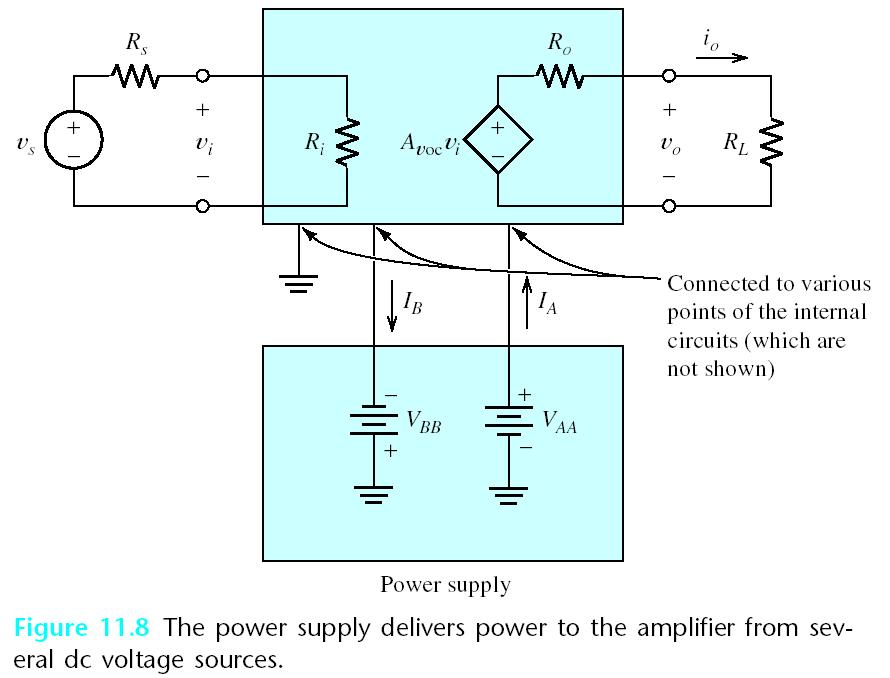
9 Voltage-Amplifier Model Input Output The input resistance R i is the equivalent resistance we see when looking into the input terminals of the amplifier. R o is the output resistance. It causes the output voltage to decrease as the load resistance becomes smaller. A voc is the open circuit voltage gain.
10 Current Gain
11 Power Gain Upper case V and I indicate Root Mean Square (RMS) values, i.e. the effective values of a fluctuating current or voltage.
12 Root Mean Square (RMS) Values V (t) = V m cos(ωt +ϑ) The average value of cos (ωt+ϕ) is zero. This is the squared version of the signal, and its mean value is ½. P Average = 1 T T 0 pdt = 1 T T 0 V m 2 cos 2 (ωt +ϑ) R dt = 1 R 1 T T V m 0 2 cos 2 (ωt +ϑ) = V 2 rms R For house power the 110 to 120 volts we are familiar with is the RMS value and the peak value is (110/0.707) or ~ 156 volts. Meters typically read RMS on the AC voltage scale unless noted otherwise.
13 Example I i Find the voltage gain, the current gain and the power gain:
14 Impedance Match for Max Power into Load 500Ω 25Ω 20 mv rms 2000Ω 500V i 25Ω What load resistance maximizes the power gain? From the Thevenin equivalent model we know that the maximum power delivered to a load is when the load resistance is equal to the Thevenin resistance of 25Ω. A v = V o R = A L 25 V voc = (500) i R o + R L = 250 G = (A v ) 2 R i R L = (250) = 5x10⁶
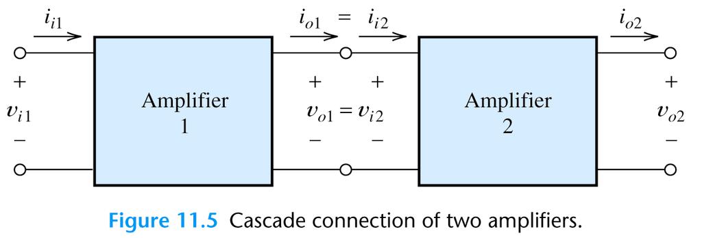
15 CASCADED AMPLIFIERS
16 Example 11.2 Find the voltage gain for each stage and for the overall cascade connection:
17 Simplified Models for Cascaded Amplifier Stages First, determine the voltage gain of the first stage accounting for loading by the second stage. The overall voltage gain is the product of the gains of the separate stages. The input impedance is that of the first stage, and the output impedance is that of the last stage.
18 Input resistance and output resistance of the cascade:
19 Simplified Model A voc =1.5x10 4 R i =1MΩ R o =100Ω But how do we find this?
20 Finding the combined open circuit voltage gain A voc2 A v1 = A voc1 R i = 200 R i2 + R o =150 (same as before) A v2 = v o2 v i2 = 100v i2 v i2 = A voc 2 A voc = A v1 A v2 = (150)(100) =1.5x10 4 =100 ( for open output circuit) ( for combination)
21

22 Heat P o >P i The additional power comes from the power supply. The efficiency is given by:

23 Find the input power, output power, supply power and the power dissipated in the amplifier. Also find the efficiency of the amplifier.

24 Input power: Output power: Supply power
Chapter 8. Chapter 9. Chapter 6. Chapter 10. Chapter 11. Chapter 7
 5.5 Series and Parallel Combinations of 246 Complex Impedances 5.6 Steady-State AC Node-Voltage 247 Analysis 5.7 AC Power Calculations 256 5.8 Using Power Triangles 258 5.9 Power-Factor Correction 261
De Anza College Department of Engineering Engr 37-Intorduction to Circuit Analysis
 De Anza College Department of Engineering Engr 37-Intorduction to Circuit Analysis Spring 2017 Lec: Mon to Thurs 8:15 am 9:20 am S48 Office Hours: Thursday7:15 am to 8:15 am S48 Manizheh Zand email: zandmanizheh@fhda.edu
CHAPTER 9. Sinusoidal Steady-State Analysis
 CHAPTER 9 Sinusoidal Steady-State Analysis 9.1 The Sinusoidal Source A sinusoidal voltage source (independent or dependent) produces a voltage that varies sinusoidally with time. A sinusoidal current source
Filter Design, Active Filters & Review. EGR 220, Chapter 14.7, December 14, 2017
 Filter Design, Active Filters & Review EGR 220, Chapter 14.7, 14.11 December 14, 2017 Overview ² Passive filters (no op amps) ² Design examples ² Active filters (use op amps) ² Course review 2 Example:
CMOS Operational-Amplifier
 CMOS Operational-Amplifier 1 What will we learn in this course How to design a good OP Amp. Basic building blocks Biasing and Loading Swings and Bandwidth CH2(8) Operational Amplifier as A Black Box Copyright
Questions Bank of Electrical Circuits
 Questions Bank of Electrical Circuits 1. If a 100 resistor and a 60 XL are in series with a 115V applied voltage, what is the circuit impedance? 2. A 50 XC and a 60 resistance are in series across a 110V
I. Introduction to Simple Circuits of Resistors
 2 Problem Set for Dr. Todd Huffman Michaelmas Term I. Introduction to Simple ircuits of esistors 1. For the following circuit calculate the currents through and voltage drops across all resistors. The
ECE : Circuits and Systems II
 ECE 202-001: Circuits and Systems II Spring 2019 Instructor: Bingsen Wang Classroom: NRB 221 Office: ERC C133 Lecture hours: MWF 8:00 8:50 am Tel: 517/355-0911 Office hours: M,W 3:00-4:30 pm Email: bingsen@egr.msu.edu
Chapter 31 Alternating Current
 Chapter 31 Alternating Current In this chapter we will learn how resistors, inductors, and capacitors behave in circuits with sinusoidally vary voltages and currents. We will define the relationship between
Syllabus for ENGR065-01: Circuit Theory
 Syllabus for ENGR065-01: Circuit Theory Fall 2017 Instructor: Huifang Dou Designation: Catalog Description: Text Books and Other Required Materials: Course Objectives Student Learning Outcomes: Course
Homework Assignment 01
 Homework Assignment 01 In this homework set students review some basic circuit analysis techniques, as well as review how to analyze ideal op-amp circuits. Numerical answers must be supplied using engineering
Electrical Circuits (2)
") Electrical Circuits (2) Lecture 1 Intro. & Review Dr.Eng. Basem ElHalawany Course Info Title Electric Circuits (2) Lecturer: Lecturer Webpage: Teaching Assistant (TA) Course Webpage References Software
Electrical Circuits (2) Lecture 1 Intro. & Review Dr.Eng. Basem ElHalawany Course Info Title Electric Circuits (2) Lecturer: Lecturer Webpage: Teaching Assistant (TA) Course Webpage References Software
Sample Question Paper
 Scheme G Sample Question Paper Course Name : Electrical Engineering Group Course Code : EE/EP Semester : Third Subject Title : Electrical Circuit and Network 17323 Marks : 100 Time: 3 hrs Instructions:
EELE 201 Circuits I. Fall 2013 (4 Credits)
") EELE 201 Circuits I Instructor: Fall 2013 (4 Credits) Jim Becker 535 Cobleigh Hall 994-5988 Office hours: Monday 2:30-3:30 pm and Wednesday 3:30-4:30 pm or by appointment EMAIL: For EELE 201-related questions,
EELE 201 Circuits I Instructor: Fall 2013 (4 Credits) Jim Becker 535 Cobleigh Hall 994-5988 Office hours: Monday 2:30-3:30 pm and Wednesday 3:30-4:30 pm or by appointment EMAIL: For EELE 201-related questions,
ECE 215 Lecture 8 Date:
 ECE 215 Lecture 8 Date: 28.08.2017 Phase Shifter, AC bridge AC Circuits: Steady State Analysis Phase Shifter the circuit current I leads the applied voltage by some phase angle θ, where 0 < θ < 90 ο depending
Homework Assignment 01
 Homework Assignment 01 In this homework set students review some basic circuit analysis techniques, as well as review how to analyze ideal op-amp circuits. Numerical answers must be supplied using engineering
Physics 115. Inductors, Capacitors, and RLC circuits. General Physics II. Session 34
 Physics 115 General Physics II Session 34 Inductors, Capacitors, and RLC circuits R. J. Wilkes Email: phy115a@u.washington.edu Home page: http://courses.washington.edu/phy115a/ 06/05/13 1 Lecture Schedule
ITT Technical Institute. ET4771 Electronic Circuit Design Onsite Course SYLLABUS
 ITT Technical Institute ET4771 Electronic Circuit Design Onsite Course SYLLABUS Credit hours: 4.5 Contact/Instructional hours: 56 (34 Theory Hours, 22 Lab Hours) Prerequisite(s) and/or Corequisite(s):
Introduction to Operational Amplifiers
 P. R. Nelson ECE 322 Fall 2012 p. 1/50 Introduction to Operational Amplifiers Phyllis R. Nelson prnelson@csupomona.edu Professor, Department of Electrical and Computer Engineering California State Polytechnic
EE 368 Electronics Lab. Experiment 10 Operational Amplifier Applications (2)
") EE 368 Electronics Lab Experiment 10 Operational Amplifier Applications (2) 1 Experiment 10 Operational Amplifier Applications (2) Objectives To gain experience with Operational Amplifier (Op-Amp). To
EE 368 Electronics Lab Experiment 10 Operational Amplifier Applications (2) 1 Experiment 10 Operational Amplifier Applications (2) Objectives To gain experience with Operational Amplifier (Op-Amp). To
Exercise 9: inductor-resistor-capacitor (LRC) circuits
 circuits") Exercise 9: inductor-resistor-capacitor (LRC) circuits Purpose: to study the relationship of the phase and resonance on capacitor and inductor reactance in a circuit driven by an AC signal. Introduction
Exercise 9: inductor-resistor-capacitor (LRC) circuits Purpose: to study the relationship of the phase and resonance on capacitor and inductor reactance in a circuit driven by an AC signal. Introduction
CHAPTER 6: ALTERNATING CURRENT
 CHAPTER 6: ALTERNATING CURRENT PSPM II 2005/2006 NO. 12(C) 12. (c) An ac generator with rms voltage 240 V is connected to a RC circuit. The rms current in the circuit is 1.5 A and leads the voltage by
CMOS Operational-Amplifier
 CMOS Operational-Amplifier 1 What will we learn in this course How to design a good OP Amp. Basic building blocks Biasing and Loading Swings and Bandwidth CH2(8) Operational Amplifier as A Black Box Copyright
CHAPTER 7. Response of First-Order RL and RC Circuits
 CHAPTER 7 Response of First-Order RL and RC Circuits RL and RC Circuits RL (resistor inductor) and RC (resistor-capacitor) circuits. Figure 7.1 The two forms of the circuits for natural response. (a) RL
ESE 230 Syllabus Prof. D. L. Rode
 ESE 230 Syllabus Prof. D. L. Rode Course Description: ESE 230. "Introduction to Electrical & Electronic Circuits" Electron and ion motion, electrical current and voltage. Electrical energy, current, voltage,
ELEN 140 ELECTRICAL CIRCUITS II Winter 2013
 ELEN 140 ELECTRICAL CIRCUITS II Winter 2013 Professor: Stephen O Loughlin Prerequisite: ELEN 130 Office: C234B Co-requisite: none Office Ph: (250) 762-5445 ext 4376 Lecture: 3.0 hrs/week Email: soloughlin@okanagan.bc.ca
Homework Assignment 06
 Question 1 (2 points each unless noted otherwise) Homework Assignment 06 1. True or false: when transforming a circuit s diagram to a diagram of its small-signal model, we replace dc constant current sources
Chapter 11. Alternating Current
 Unit-2 ECE131 BEEE Chapter 11 Alternating Current Objectives After completing this chapter, you will be able to: Describe how an AC voltage is produced with an AC generator (alternator) Define alternation,
ELECTRIC CIRCUITS. Third Edition JOSEPH EDMINISTER MAHMOOD NAHVI
 ELECTRIC CIRCUITS Third Edition JOSEPH EDMINISTER MAHMOOD NAHVI Includes 364 solved problems --fully explained Complete coverage of the fundamental, core concepts of electric circuits All-new chapters
Homework Assignment 13
 Question 1 Short Takes 2 points each. Homework Assignment 13 1. Classify the type of feedback uses in the circuit below (i.e., shunt-shunt, series-shunt, ) 2. True or false: an engineer uses series-shunt
Source Transformation
 HW Chapter 0: 4, 20, 26, 44, 52, 64, 74, 92. Source Transformation Source transformation in frequency domain involves transforming a voltage source in series with an impedance to a current source in parallel
What s an Analog Signal?
 What s an Analog Signal? Derived from the word analogous (analogous to the original signal) Our most powerful electronic systems are digital systems, e.g. computers, however, analog signals are required
ECE3204 D2015 Lab 1. See suggested breadboard configuration on following page!
 ECE3204 D2015 Lab 1 The Operational Amplifier: Inverting and Non-inverting Gain Configurations Gain-Bandwidth Product Relationship Frequency Response Limitation Transfer Function Measurement DC Errors
EQUIVALENT EQUIPMENT CIRCUITS
 INTRODUCTION EQUIVALENT EQUIPMENT CIRCUITS The student will analyze the internal properties of the equipment used in lab. The input resistance of the oscilloscope and digital multimeter when used as a
EE42: Running Checklist of Electronics Terms Dick White
 EE42: Running Checklist of Electronics Terms 14.02.05 Dick White Terms are listed roughly in order of their introduction. Most definitions can be found in your text. Terms2 TERM Charge, current, voltage,
Goals. Introduction. To understand the use of root mean square (rms) voltages and currents.
 voltages and currents.") Lab 10. AC Circuits Goals To show that AC voltages cannot generally be added without accounting for their phase relationships. That is, one must account for how they vary in time with respect to one another.
Lab 10. AC Circuits Goals To show that AC voltages cannot generally be added without accounting for their phase relationships. That is, one must account for how they vary in time with respect to one another.
Microelectronic Circuits - Fifth Edition Sedra/Smith Copyright 2004 by Oxford University Press, Inc.
 Feedback 1 Figure 8.1 General structure of the feedback amplifier. This is a signal-flow diagram, and the quantities x represent either voltage or current signals. 2 Figure E8.1 3 Figure 8.2 Illustrating
Instructions for the final examination:
 School of Information, Computer and Communication Technology Sirindhorn International Institute of Technology Thammasat University Practice Problems for the Final Examination COURSE : ECS304 Basic Electrical
Designing Information Devices and Systems II Spring 2019 A. Sahai, J. Roychowdhury, K. Pister Homework 2
 EECS 16B Designing Information Devices and Systems II Spring 2019 A. Sahai, J. Roychowdhury, K. Pister Homework 2 This homework is due on Wednesday, February 13, 2019, at 11:59PM. Self-grades are due on
ECE 2006 University of Minnesota Duluth Lab 11. AC Circuits
 1. Objective AC Circuits In this lab, the student will study sinusoidal voltages and currents in order to understand frequency, period, effective value, instantaneous power and average power. Also, the
PHYS 235: Homework Problems
 PHYS 235: Homework Problems 1. The illustration is a facsimile of an oscilloscope screen like the ones you use in lab. sinusoidal signal from your function generator is the input for Channel 1, and your
ET475 Electronic Circuit Design I [Onsite]
![ET475 Electronic Circuit Design I [Onsite]](/thumbs/89/98281525.jpg "ET475 Electronic Circuit Design I [Onsite]") ET475 Electronic Circuit Design I [Onsite] Course Description: This course covers the analysis and design of electronic circuits, and includes a laboratory that utilizes computer-aided software tools for
ET475 Electronic Circuit Design I [Onsite] Course Description: This course covers the analysis and design of electronic circuits, and includes a laboratory that utilizes computer-aided software tools for
ME 365 EXPERIMENT 7 SIGNAL CONDITIONING AND LOADING
 ME 365 EXPERIMENT 7 SIGNAL CONDITIONING AND LOADING Objectives: To familiarize the student with the concepts of signal conditioning. At the end of the lab, the student should be able to: Understand the
Lecture Notes Unit-III
 Lecture Notes Unit-III FAQs Q1: An operational amplifier has a differential gain of 103 and CMRR of 100, input voltages are 120µV and 80µV, determine output voltage. 2 MARKS
Homework Assignment 12
 Homework Assignment 12 Question 1 Shown the is Bode plot of the magnitude of the gain transfer function of a constant GBP amplifier. By how much will the amplifier delay a sine wave with the following
University of Southern California. Department of Electrical Engineering Electrophysics. EE 326Lx - Essentials of Electrical Engineering
 University of Southern California Department of Electrical Engineering Electrophysics EE 326Lx - Essentials of Electrical Engineering Course Syllabus Fall 2003 Abstract EE 326Lx serves as an introduction
Electromagnetic Oscillations and Currents. March 23, 2014 Chapter 30 1
 Electromagnetic Oscillations and Currents March 23, 2014 Chapter 30 1 Driven LC Circuit! The voltage V can be thought of as the projection of the vertical axis of the phasor V m representing the time-varying
EE 340L EXPERIMENT # 5.1 SYNCHRONOUS GENERATOR (STAND-ALONE OPERATION)
") EE 340L EXPERIMENT # 5.1 SYNCHRONOUS GENERATOR (STAND-ALONE OPERATION) A. Equivalent Circuit Parameters A.1. Open-Circuit Test (a) Mechanically couple the generator with a shunt-excited DC motor as shown
EE 340L EXPERIMENT # 5.1 SYNCHRONOUS GENERATOR (STAND-ALONE OPERATION) A. Equivalent Circuit Parameters A.1. Open-Circuit Test (a) Mechanically couple the generator with a shunt-excited DC motor as shown
Chapter 6. BJT Amplifiers
 Basic Electronic Devices and Circuits EE 111 Electrical Engineering Majmaah University 2 nd Semester 1432/1433 H Chapter 6 BJT Amplifiers 1 Introduction The things you learned about biasing a transistor
ECE215 Lecture 7 Date:
 Lecture 7 Date: 29.08.2016 AC Circuits: Impedance and Admittance, Kirchoff s Laws, Phase Shifter, AC bridge Impedance and Admittance we know: we express Ohm s law in phasor form: where Z is a frequency-dependent
Chapter 25 Alternating Currents
 Chapter 25 Alternating Currents GOALS When you have mastered the contents of this chapter, you will be able to achieve the following goals: Definitions Define each of the following terms and use it in
Question Paper Profile
 I Scheme Question Paper Profile Program Name : Electrical Engineering Program Group Program Code : EE/EP/EU Semester : Third Course Title : Electrical Circuits Max. Marks : 70 Time: 3 Hrs. Instructions:
UNIVERSITY OF BOLTON SCHOOL OF SPORT AND BIOMEDICAL SCIENCE. BEng (HONS)/MEng BIOMEDICAL ENGINEERING. BEng (HONS) MEDICAL ENGINEERING
/MEng BIOMEDICAL ENGINEERING. BEng (HONS) MEDICAL ENGINEERING") LH29 SCHOOL OF SPORT AND BIOMEDICAL SCIENCE BEng (HONS)/MEng BIOMEDICAL ENGINEERING BEng (HONS) MEDICAL ENGINEERING SEMESTER 2 EXAMINATIONS 2015/2016 MODULE NO: BME4004 Date: Wednesday 18 May 2016 Time:
LH29 SCHOOL OF SPORT AND BIOMEDICAL SCIENCE BEng (HONS)/MEng BIOMEDICAL ENGINEERING BEng (HONS) MEDICAL ENGINEERING SEMESTER 2 EXAMINATIONS 2015/2016 MODULE NO: BME4004 Date: Wednesday 18 May 2016 Time:
Homework Assignment 03
 Homework Assignment 03 Question 1 (Short Takes), 2 points each unless otherwise noted. 1. Two 0.68 μf capacitors are connected in series across a 10 khz sine wave signal source. The total capacitive reactance
Chapter 1. Electronics and Semiconductors
 Chapter 1. Electronics and Semiconductors Tong In Oh 1 Objective Understanding electrical signals Thevenin and Norton representations of signal sources Representation of a signal as the sum of sine waves
Lecture Week 7. Quiz 4 - KCL/KVL Capacitors RC Circuits and Phasor Analysis RC filters Workshop
 Lecture Week 7 Quiz 4 - KCL/KVL Capacitors RC Circuits and Phasor Analysis RC filters Workshop Quiz 5 KCL/KVL Please clear desks and turn off phones and put them in back packs You need a pencil, straight
SIDDHARTH GROUP OF INSTITUTIONS :: PUTTUR (AUTONOMOUS) Siddharth Nagar, Narayanavanam Road QUESTION BANK (DESCRIPTIVE) UNIT I INTRODUCTION
 Siddharth Nagar, Narayanavanam Road QUESTION BANK (DESCRIPTIVE) UNIT I INTRODUCTION") SIDDHARTH GROUP OF INSTITUTIONS :: PUTTUR (AUTONOMOUS) Siddharth Nagar, Narayanavanam Road 517583 QUESTION BANK (DESCRIPTIVE) Subject with Code : Electrical Circuits(16EE201) Year & Sem: I-B.Tech & II-Sem
SIDDHARTH GROUP OF INSTITUTIONS :: PUTTUR (AUTONOMOUS) Siddharth Nagar, Narayanavanam Road 517583 QUESTION BANK (DESCRIPTIVE) Subject with Code : Electrical Circuits(16EE201) Year & Sem: I-B.Tech & II-Sem
Homework Assignment 02
 Question 1 (2 points each unless noted otherwise) 1. Is the following circuit an STC circuit? Homework Assignment 02 (a) Yes (b) No (c) Need additional information Answer: There is one reactive element
EE105 Fall 2015 Microelectronic Devices and Circuits. Amplifier Gain
 EE05 Fall 205 Microelectronic Devices and Circuits Prof. Ming C. Wu wu@eecs.berkeley.edu 5 Sutardja Dai Hall (SDH) 2- Amplifier Gain Voltage Gain: Current Gain: Power Gain: Note: A v v O v I A i i O i
Hours / 100 Marks Seat No.
 17323 14115 3 Hours / 100 Seat No. Instructions (1) All Questions are Compulsory. (2) Illustrate your answers with neat sketches wherever necessary. (3) Figures to the right indicate full marks. (4) Assume
Operational Amplifier BME 360 Lecture Notes Ying Sun
 Operational Amplifier BME 360 Lecture Notes Ying Sun Characteristics of Op-Amp An operational amplifier (op-amp) is an analog integrated circuit that consists of several stages of transistor amplification
Equivalent Equipment Circuits
 1. Introduction Equivalent Equipment Circuits The student will analyze the internal properties of the equipment used in lab. The input resistance of the oscilloscope and Digital MultiMeter (DMM) when used
University of Jordan School of Engineering Electrical Engineering Department. EE 219 Electrical Circuits Lab
 University of Jordan School of Engineering Electrical Engineering Department EE 219 Electrical Circuits Lab EXPERIMENT 7 RESONANCE Prepared by: Dr. Mohammed Hawa EXPERIMENT 7 RESONANCE OBJECTIVE This experiment
EE202 Circuit Theory II , Spring
 EE202 Circuit Theory II 2018-2019, Spring I. Introduction & Review of Circuit Theory I (3 Hrs.) Introduction II. Sinusoidal Steady-State Analysis (Chapter 9 of Nilsson - 9 Hrs.) (by Y.Kalkan) The Sinusoidal
Goals. Introduction. To understand the use of root mean square (rms) voltages and currents.
 voltages and currents.") Lab 10. AC Circuits Goals To show that AC voltages cannot generally be added without accounting for their phase relationships. That is, one must account for how they vary in time with respect to one another.
Lab 10. AC Circuits Goals To show that AC voltages cannot generally be added without accounting for their phase relationships. That is, one must account for how they vary in time with respect to one another.
EE301 ELECTRONIC CIRCUITS CHAPTER 2 : OSCILLATORS. Lecturer : Engr. Muhammad Muizz Bin Mohd Nawawi
 EE301 ELECTRONIC CIRCUITS CHAPTER 2 : OSCILLATORS Lecturer : Engr. Muhammad Muizz Bin Mohd Nawawi 2.1 INTRODUCTION An electronic circuit which is designed to generate a periodic waveform continuously at
ELEG 205 Analog Circuits Laboratory Manual Fall 2017
 ELEG 205 Analog Circuits Laboratory Manual Fall 2017 University of Delaware Dr. Mark Mirotznik Kaleb Burd Aric Lu Patrick Nicholson Colby Banbury Table of Contents Policies Policy Page 3 Labs Lab 1: Intro
55:041 Electronic Circuits The University of Iowa Fall Exam 3. Question 1 Unless stated otherwise, each question below is 1 point.
 Exam 3 Name: Score /65 Question 1 Unless stated otherwise, each question below is 1 point. 1. An engineer designs a class-ab amplifier to deliver 2 W (sinusoidal) signal power to an resistive load. Ignoring
Bucking Coils produce Energy Gain Cyril Smith, 2015
 Bucking Coils produce Energy Gain Cyril Smith, 015 1. Introduction There are many claims of overunity for systems that employ bucking coils. These are coils mounted on a common core and connected in series
EE 221 CIRCUITS II. Chapter 12 Three-Phase Circuit
 EE 221 CRCUTS Chapter 12 Three-Phase Circuit 1 THREE-PHASE CRCUTS CHAPTER 12 12.1 What is a Three-Phase Circuit? 12.2 Balanced Three-Phase oltages 12.3 Balanced Three-Phase Connection 12.4 Power in a Balanced
1. An engineer measures the (step response) rise time of an amplifier as. Estimate the 3-dB bandwidth of the amplifier. (2 points)
 rise time of an amplifier as. Estimate the 3-dB bandwidth of the amplifier. (2 points)") Exam 1 Name: Score /60 Question 1 Short Takes 1 point each unless noted otherwise. 1. An engineer measures the (step response) rise time of an amplifier as. Estimate the 3-dB bandwidth of the amplifier.
Exam 1 Name: Score /60 Question 1 Short Takes 1 point each unless noted otherwise. 1. An engineer measures the (step response) rise time of an amplifier as. Estimate the 3-dB bandwidth of the amplifier.
ENGINEERING COUNCIL CERTIFICATE LEVEL ENGINEERING SCIENCE C103 TUTORIAL 18 ALTERNATING CURRENT
 ENGINEERING OUNIL ERTIFIATE LEVEL ENGINEERING SIENE 03 TUTORIAL 8 ALTERNATING URRENT On completion of this tutorial you should be able to do the following. Explain alternating current. Explain Root Mean
CIRCUITS, SYSTEMS, AND SIGNALS FOR BIOENGINEERS: A MATLAB-BASED INTRODUCTION
 CIRCUITS, SYSTEMS, AND SIGNALS FOR BIOENGINEERS: A MATLAB-BASED INTRODUCTION John L. Semmlow ELSEVIER ACAUEMIC PRFSS AMSTERDAM BOSTON HEIDELBERG LONDON NEW YORK OXFORD PARIS SAN DIEGO SAN FRANCISCO SINGAPORE
University of Southern C alifornia School Of Engineering Department Of Electrical Engineering
 University of Southern alifornia School Of Engineering Department Of Electrical Engineering EE 348: Homework Assignment #02 Spring, 2001 (Due 02/01/2001) homa Problem #05: The amplifier module in Fig.
Electronic Devices. Floyd. Chapter 6. Ninth Edition. Electronic Devices, 9th edition Thomas L. Floyd
 Electronic Devices Ninth Edition Floyd Chapter 6 Agenda BJT AC Analysis Linear Amplifier AC Load Line Transistor AC Model Common Emitter Amplifier Common Collector Amplifier Common Base Amplifier Special
Lab 6: Building a Function Generator
 ECE 212 Spring 2010 Circuit Analysis II Names: Lab 6: Building a Function Generator Objectives In this lab exercise you will build a function generator capable of generating square, triangle, and sine
Electricity and Magnetism Transformers and Alternating Current
 Electricity and Magnetism Transformers and Alternating Current Lana Sheridan De Anza College Mar 16, 2018 Last time mutual inductance LC circuits and oscillations Overview LC circuits, mechanical analogy
PHYSICS 330 LAB Operational Amplifier Frequency Response
 PHYSICS 330 LAB Operational Amplifier Frequency Response Objectives: To measure and plot the frequency response of an operational amplifier circuit. History: Operational amplifiers are among the most widely
Lecture Week 8. Quiz #5 KCL/KVL Homework P15 Capacitors RC Circuits and Phasor Analysis RC filters Bode Plots Cutoff frequency Homework
 Lecture Week 8 Quiz #5 KCL/KVL Homework P15 Capacitors RC Circuits and Phasor Analysis RC filters Bode Plots Cutoff frequency Homework Quiz 5 KCL/KVL (20 pts.) Please clear desks and turn off phones and
Chapter 30 Inductance, Electromagnetic. Copyright 2009 Pearson Education, Inc.
 Chapter 30 Inductance, Electromagnetic Oscillations, and AC Circuits 30-7 AC Circuits with AC Source Resistors, capacitors, and inductors have different phase relationships between current and voltage
OPERATIONAL AMPLIFIER PREPARED BY, PROF. CHIRAG H. RAVAL ASSISTANT PROFESSOR NIRMA UNIVRSITY
 OPERATIONAL AMPLIFIER PREPARED BY, PROF. CHIRAG H. RAVAL ASSISTANT PROFESSOR NIRMA UNIVRSITY INTRODUCTION Op-Amp means Operational Amplifier. Operational stands for mathematical operation like addition,
PHYSICS 221 LAB #6: CAPACITORS AND AC CIRCUITS
 Name: Partners: PHYSICS 221 LAB #6: CAPACITORS AND AC CIRCUITS The electricity produced for use in homes and industry is made by rotating coils of wire in a magnetic field, which results in alternating
ECE2210 Final given: Fall 12
 ECE Final given: Fall (5 pts) a) Find and draw the Thévenin equivalent of the circuit shown The load resistor is R L b) Find and draw the Norton equivalent of the same circuit c) Find the load current
Alternating current circuits- Series RLC circuits
 FISI30 Física Universitaria II Professor J.. ersosimo hapter 8 Alternating current circuits- Series circuits 8- Introduction A loop rotated in a magnetic field produces a sinusoidal voltage and current.
Lecture 16: Small Signal Amplifiers
 Lecture 16: Small Signal Amplifiers Prof. Niknejad Lecture Outline Review: Small Signal Analysis Two Port Circuits Voltage Amplifiers Current Amplifiers Transconductance Amps Transresistance Amps Example:
Lecture Week 4. Homework Voltage Divider Equivalent Circuit Observation Exercise
 Lecture Week 4 Homework Voltage Divider Equivalent Circuit Observation Exercise Homework: P6 Prove that the equation relating change in potential energy to voltage is dimensionally consistent, using the
ECE 303 ELECTRONICS LABORATORY SPRING No labs meet this week. Course introduction & lab safety
 ECE 303 ELECTRONICS LABORATORY SPRING 2018 Week of Jan. 8 Jan. 15 Jan. 22 Jan. 29 Feb. 5 Feb. 12 Feb. 19 Feb. 26 Mar. 5 Mar. 12 Mar. 19 Mar. 26 Apr. 2 Apr. 9 Apr. 16 Topic No labs meet this week Course
An induced emf is the negative of a changing magnetic field. Similarly, a self-induced emf would be found by
 This is a study guide for Exam 4. You are expected to understand and be able to answer mathematical questions on the following topics. Chapter 32 Self-Induction and Induction While a battery creates an
Homework Assignment 10
 Homework Assignment 10 Question The amplifier below has infinite input resistance, zero output resistance and an openloop gain. If, find the value of the feedback factor as well as so that the closed-loop
Chapter 7. Copyright The McGraw-Hill Companies, Inc. Permission required for reproduction or display.
 Chapter 7 Copyright The McGraw-Hill Companies, Inc. Permission required for reproduction or display. Learning Objectives 1. Understand the meaning of instantaneous and average power, master AC power notation,
Lab 3 Transient Response of RC & RL Circuits
 Lab 3 Transient Response of RC & RL Circuits Last Name: First Name: Student Number: Lab Section: Monday Tuesday Wednesday Thursday Friday TA Signature: Note: The Pre-Lab section must be completed prior
ENGR4300 Test 3A Fall 2002
 1. 555 Timer (20 points) Figure 1: 555 Timer Circuit For the 555 timer circuit in Figure 1, find the following values for R1 = 1K, R2 = 2K, C1 = 0.1uF. Show all work. a) (4 points) T1: b) (4 points) T2:
Precision Rectifier Circuits
 Precision Rectifier Circuits Rectifier circuits are used in the design of power supply circuits. In such applications, the voltage being rectified are usually much greater than the diode voltage drop,
MAE334 - Introduction to Instrumentation and Computers. Final Exam. December 11, 2006
 MAE334 - Introduction to Instrumentation and Computers Final Exam December 11, 2006 o Closed Book and Notes o No Calculators 1. Fill in your name on side 2 of the scoring sheet (Last name first!) 2. Fill
AC : A CIRCUITS COURSE FOR MECHATRONICS ENGINEERING
 AC 2010-2256: A CIRCUITS COURSE FOR MECHATRONICS ENGINEERING L. Brent Jenkins, Southern Polytechnic State University American Society for Engineering Education, 2010 Page 15.14.1 A Circuits Course for
Quiz 6 Op-Amp Characteristics
 Lecture Week 11 Quiz 6: Op-Amp Characteristics Complex Numbers and Phasor Domain Review Passive Filters Review Active Filters Complex Impedance and Bode Plots Workshop Quiz 6 Op-Amp Characteristics Please
2.0 AC CIRCUITS 2.1 AC VOLTAGE AND CURRENT CALCULATIONS. ECE 4501 Power Systems Laboratory Manual Rev OBJECTIVE
 2.0 AC CIRCUITS 2.1 AC VOLTAGE AND CURRENT CALCULATIONS 2.1.1 OBJECTIVE To study sinusoidal voltages and currents in order to understand frequency, period, effective value, instantaneous power and average
Section 4: Operational Amplifiers
 Section 4: Operational Amplifiers Op Amps Integrated circuits Simpler to understand than transistors Get back to linear systems, but now with gain Come in various forms Comparators Full Op Amps Differential
Half-wave Rectifier AC Meters
 Note-4 1 Half-wave Rectifier AC Meters Disadvantages: 1. In negative half-cycle, reverse current flows through the circuit reduces average value of current meter reads lower than actual. 2. High peak inverse
An electronic unit that behaves like a voltagecontrolled
 1 An electronic unit that behaves like a voltagecontrolled voltage source. An active circuit element that amplifies, sums, subtracts, multiply, divide, differentiate or integrates a signal 2 A typical