10W Class D Stereo Amplifier Kit
|
|
|
- Pamela Barber
- 5 years ago
- Views:
Transcription
 Ltd Electronic Kits and Modules K1420 High power multipurpose audio amplifier")

1 1 Total Solder Joints: 70 Difficulty Level : beginner expert 10W Class D Stereo Amplifier Kit PARADIGM Technologies (UK) Ltd Electronic Kits and Modules K1420 High power multipurpose audio amplifier Specifications High power output up to 10Wrms/channel into 8ohm Advanced Power-Off Pop Reduction Power Supply 10V 26V / 250mA Thermal and Short-Circuit Protection with Auto Recovery Dimensions 68.6mm x 73.7mm ( 2.7 x 2.9 )
2 2 Features and Specifications Features The kit uses a TPA3125D2 stereo audio power amplifier that is capable of delivering up to 10W per channel of continuous average power into a 8-Ω load at 10% THD+N or 8W per channel at 1% THD+N. The gain of each channel is fixed at 20dB. This kit uses the 20-pin thermally enhanced DIP package (NE). The kit utilises a high quality PCB made from 1.6mm thick FR4 fibreglass along with specially selected components from highly regarded manufacturers such as Panasonic and Rohm. Paradigm Technologies have designed a fully symmetrical PCB around the TPA3125D2 chipset to ensure that maximum performance is obtained. Fully symmetrical PCBs are usually only found in high end audio amplifier designs!! They are used to ensure that left and right channels have identical performance characteristics. This gives a rock solid stereo soundstage, through improved phase coherence compared to a standard layout PCB. Specifications High power output 10Wrms/channel into 8ohm Advanced Power-Off Pop Reduction Efficient Class-D Operation Eliminates Need for Heat Sinks Crosstalk = -70dB (Po = 1W, f = 1 khz, gain = 20 db) Power Supply 10V 26V / 250mA Thermal and Short-Circuit Protection with Auto Recovery Dimensions 68.6mm x 73.7mm ( 2.7 x 2.9 )
3 3 Assembly Hints and Tips Assembly - Please read the following hints and tips carefully. They will help you to build this project successfully. Tools Required A good quality soldering iron (25-40W) with a small tip During soldering, wipe the soldering iron tip often on a wet sponge/cloth, to keep the tip clean. Then apply solder to the tip, to give it a wet look. This is called tinning and will protect the tip and enables you to make good soldered connections. When solder rolls off the tip, it needs cleaning. Use thin resin-cored solder. Do NOT use any flux or grease. Diagonal cutters to trim excess leads. To avoid injury when cutting excess leads, hold the lead away from you when you cut to prevent the cut parts from flying towards your eyes. Needle nose pliers, for bending leads or to hold components in place. Small flat head and Philips head screwdrivers. A basic range is fine. A basic multi-meter will be required for some projects and could prove useful for identifying/measuring some components. Assembly Hints Ensure skill level required for this kit matches your own ability Follow the instructions carefully. Read and understand the entire step before you perform each operation. Perform the assembly in the correct order as stated in this manual. Position all parts on the PCB (Printed Circuit Board) as shown on the drawings Values on the circuit diagram are subject to change Values in this assembly guide are correct* Use the check boxes to mark your progress Please read the included information on safety and customer service *Typographical inaccuracies excluded. Always check for possible last minute manual updates, indicated as (Note) on a separate leaflet
4 4 Assembly Hints and Tips Soldering Hints Mount the component against the PCB surface and carefully solder the leads. Make sure the solder joints are cone shaped and shiny. Trim excess leads as close as possible to the solder joint. Follow the order of build and check component values before fitting consult resistor / capacitor charts if unsure of component value!
5 5 Construction PCB = K1420v1.1 Inductors L1, L2 = 22µH Resistors R1, R2 = 4.7kΩ IC1 = TPA3125D2 Capacitors C2, C13, C16 = 0.1µF Electrolytic C4, C5 = 0.22µF Electrolytic C9, C10 = 0.68µF Electrolytic C1, C6, C11, C12 = 1µF Electrolytic C3 = 10µF Electrolytic C7, C8, C14, C15 = 470µF Electrolytic
6 6 Circuit Diagram

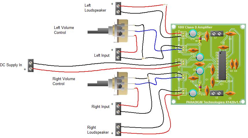
7 7 Wiring Diagram
10W Class D Ultra Stereo Amplifier Kit
 1 Total Solder Joints: 70 Difficulty Level : beginner expert PARADIGM Technologies (UK) Ltd Electronic Kits and Modules 10W Class D Ultra Stereo Amplifier Kit K1421 High power / quality audio amplifier
Total solder points: 33 Difficulty level: beginner advanced. 7W mono amplifier K4001 ILLUSTRATED ASSEMBLY MANUAL
 Total solder points: 33 Difficulty level: beginner 1 2 3 4 5 advanced 7W mono amplifier K4001 Small but powerful multipurpose amplifier. ILLUSTRATED ASSEMBLY MANUAL H4001IP-1 2 Features & Specifications
Total solder points: 42 Difficulty level: beginner advanced UNIVERSAL STEREO PRE - AMPLIFIER K2572 ILLUSTRATED ASSEMBLY MANUAL
 Total solder points: 42 Difficulty level: beginner 1 2 3 4 5 advanced UNIVERSAL STEREO PRE - AMPLIFIER K2572 Low noise preamplifier to boost small signals. ILLUSTRATED ASSEMBLY MANUAL H2572IP-1 Features
K8066 3W MONO AMPLIFIER. Specifications
 Total solder points: 34 Difficulty level: beginner 1 2 3 4 5 advanced 3W MONO AMPLIFIER K8066 Small but powerful amplifier suits a wide range of applications. Specifications Output power : 3Wrms (4-8 ohm,
Total solder points: 198 Difficulty level: beginner advanced DUAL ELECTRONIC DICE K3400 ILLUSTRATED ASSEMBLY MANUAL
 Total solder points: 198 Difficulty level: beginner 1 2 3 4 5 advanced DUAL ELECTRONIC DICE K3400 Cheating is no longer possible! ILLUSTRATED ASSEMBLY MANUAL H3400IP-1 Features & Specifications Features:
Total solder points: 79 Difficulty level: beginner advanced GUITAR PREAMPLIFIER WITH HEADPHONE OUTPUT K4102 ILLUSTRATED ASSEMBLY MANUAL
 Total solder points: 79 Difficulty level: beginner 1 2 3 4 5 advanced GUITAR PREAMPLIFIER WITH HEADPHONE OUTPUT K4102 Practice the guitar without disturbing others. ILLUSTRATED ASSEMBLY MANUAL H4102IP-1
400W MONO/STEREO AMPLIFIER
 400W MONO/STEREO AMPLIFIER Universal, robust and compact are the words to describe this amplifier. Total solder points: 264 Difficulty level: beginner 1 2 3 4 5 advanced K4005B ILLUSTRATED ASSEMBLY MANUAL
Total solder points: 271 Difficulty level: beginner advanced. 2 x 15 LED STEREO VU METER K4306 ILLUSTRATED ASSEMBLY MANUAL
 Total solder points: 271 Difficulty level: beginner 1 2 3 4 5 advanced 2 x 15 LED STEREO VU METER K4306 For high precision audio level indication ILLUSTRATED ASSEMBLY MANUAL H4306IP-1 Features & Specifications
Total solder points: 163 Difficulty level: beginner advanced SPEAKER PROTECTION KIT K4700 ILLUSTRATED ASSEMBLY MANUAL
 Total solder points: 163 Difficulty level: beginner 1 2 3 4 5 advanced SPEAKER PROTECTION KIT K4700 Protects your precious speakers against switch-on clicks and DC current. ILLUSTRATED ASSEMBLY MANUAL
Total solder points: 108 Difficulty level: beginner advanced PINK NOISE GENERATOR K4301 ILLUSTRATED ASSEMBLY MANUAL H4301IP-1
 Total solder points: 108 Difficulty level: beginner 1 2 3 4 5 advanced PINK NOISE GENERATOR K4301 Add a spectrum analyser with a microphone and check your audio system performance. ILLUSTRATED ASSEMBLY
Total solder points: Difficulty level: beginner advanced 3 DIGIT PANEL METER KIT K2032 ILLUSTRATED ASSEMBLY MANUAL
 Total solder points: 65 + 49 Difficulty level: beginner 1 2 3 4 5 advanced 3 DIGIT PANEL METER KIT K2032 Ideal replacement for moving coil meters ILLUSTRATED ASSEMBLY MANUAL H2032IP-1 Features & Specifications
Total solder points: 82 Difficulty level: beginner advanced. Dc to Pulse Width Modulator K8004 ILLUSTRATED ASSEMBLY MANUAL
 Total solder points: 82 Difficulty level: beginner 1 2 3 4 5 advanced Dc to Pulse Width Modulator K8004 Allows very efficient control of DC motors, heaters or lights. ILLUSTRATED ASSEMBLY MANUAL H8004IP-2
K2601 STROBOSCOPE. Features
 Total solder points: 38 Difficulty level: beginner 1 2 3 4 5 advanced STROBOSCOPE K2601 Great for party s, stage, photography,... Features Power supply : 220-240VAC Power consumption : 3-10W Flash frequency
Total solder points: 101 Difficulty level: beginner advanced ELECTRONIC WATCHDOG K2655 ILLUSTRATED ASSEMBLY MANUAL
 Total solder points: 101 Difficulty level: beginner 1 2 3 4 5 advanced ELECTRONIC WATCHDOG K2655 Listens and scares intruders with realistic barking. ILLUSTRATED ASSEMBLY MANUAL H2655IP-2 Features & Specifications
Total solder points: Difficulty level: beginner advanced 0 TO 60 HOUR START / STOP TIMER K6200 ILLUSTRATED ASSEMBLY MANUAL
 Total solder points: 96 + 43 Difficulty level: beginner 1 2 3 4 5 advanced 0 TO 60 HOUR START / STOP TIMER K6200 Broad range mains operated start / stop timer. ILLUSTRATED ASSEMBLY MANUAL H6200IP-1 VELLEMAN
VOLUME AND TONE CONTROL - PREAMPLIFIER K8084
 VOLUME AND TONE CONTROL - PREAMPLIFIER K8084 When using one of our amplifiers (big or small), you always need a volume control and preferably also a tone control H8084IP-1 Features & specifications When
Total solder points: 338 Difficulty level: beginner advanced. Remote control by telephone K6501 ILLUSTRATED ASSEMBLY MANUAL
 Total solder points: 338 Difficulty level: beginner 1 2 3 4 5 advanced Remote control by telephone K6501 Operate your appliances from anywhere with a simple phone call. ILLUSTRATED ASSEMBLY MANUAL H6501IP-1
Total solder points: 47 Difficulty level: beginner advanced METAL DETECTOR K7102 ILLUSTRATED ASSEMBLY MANUAL
 Total solder points: 47 Difficulty level: beginner 1 2 3 4 5 advanced METAL DETECTOR K7102 Avoid disasters when drilling holes in walls... ILLUSTRATED ASSEMBLY MANUAL H7102IP Features & Specifications
Total solder points: 247 Difficulty level: beginner advanced. 10 Channel, 2-Wire REMOTE CONTROL K8023 ILLUSTRATED ASSEMBLY MANUAL
 Total solder points: 247 Difficulty level: beginner 1 2 3 4 5 advanced 10 Channel, 2-Wire REMOTE CONTROL K8023 Control up to 10 devices from a distance using only 2 wires. ILLUSTRATED ASSEMBLY MANUAL H8023IP-1
Total solder points: 77 Difficulty level: beginner advanced OPTICAL PROXIMITY SWITCH K8092 ILLUSTRATED ASSEMBLY MANUAL
 Total solder points: 77 Difficulty level: beginner 1 2 3 4 5 advanced OPTICAL PROXIMITY SWITCH K8092 Operate by waving hand or object in front of unit ILLUSTRATED ASSEMBLY MANUAL H8092IP-1 Features & Specifications
Power shield that can drive: relays, solenoids, DC and stepper motors
 ILLUSTRATED KA0IP LUSTRA TED ASSEMBLY SE MANUAL AL HKA0IP Motor & Power shield Arduino Power shield that can drive: relays, solenoids, DC and stepper motors Features For use with Arduino Due, Arduino Uno,
Total solder points: 66 Difficulty level: beginner advanced. 15 Channel IR remote stick K8051 ILLUSTRATED ASSEMBLY MANUAL
 Total solder points: 66 Difficulty level: beginner 1 2 3 4 5 advanced 15 Channel IR remote stick K8051 Sleek designer enclosure with just 2 buttons, yet it provides acces to a stunning 15 channels. ILLUSTRATED
Total solder points: 63 Difficulty level: beginner advanced 2 CHANNEL RF CODELOCK TRANSMITTER K8059 ILLUSTRATED ASSEMBLY MANUAL
 Total solder points: 63 Difficulty level: beginner 1 2 3 4 5 advanced 2 CHANNEL RF CODELOCK TRANSMITTER K8059 For use with K8057/VM109 2 Channel RF receiver ILLUSTRATED ASSEMBLY MANUAL H8059IP-1 VELLEMAN
Total solder points: 47 Difficulty level: beginner advanced METAL DETECTOR K7102 ILLUSTRATED ASSEMBLY MANUAL
 Total solder points: 47 Difficulty level: beginner 1 2 3 4 5 advanced METAL DETECTOR K7102 Avoid disasters when drilling holes in walls... ILLUSTRATED ASSEMBLY MANUAL H7102IP Features & Specifications
K8039 DMX CONTROLLED POWER DIMMER. Control a lamp or group of lamps trough a DMX signal. Suitable for resistive and mains voltage halogen lighting.
 DMX CONTROLLED POWER DIMMER K8039 Control a lamp or group of lamps trough a DMX signal. Suitable for resistive and mains voltage halogen lighting. Specifications control source: DMX-512, 3 pin XLR socket
K8055N. USB Experiment interface board. Interface your computer with the world using 5 digital in and 8 outputs, 2 analogue in-and outputs.
 Total solder points: 313 Difficulty level: beginner 1 2 3 4 5 advanced USB Experiment interface board K8055N Interface your computer with the world using 5 digital in and 8 outputs, 2 analogue in-and outputs.
Eight channel remote relay card. Total solder points: 277 Difficulty level: beginner advanced K8056 ILLUSTRATED ASSEMBLY MANUAL
 Eight channel remote relay card This relay card can be used in several ways : stand alone card, addressed by switches or open collector outputs or remote controlled through RS232. Total solder points:
Configure your Arduino as a simple web server or let it get data from the worldwide web.
 KA0 ILLUSTRATED LUSTRA TED ASSEMBLY SE MANUAL HKA0IP KA0 Ethernet shield for Arduino Configure your Arduino as a simple web server or let it get data from the worldwide web. Features For use with Arduino
1A POWER SUPPLY K1823
 Total solder points: 27 Skill level : 1 1A POWER SUPPLY K1823 Applications : Just add a suitable transformer (see table inside) Great to power your projects and save on batteries Use as adjustable power
πλ² Synthesizer Manual for Assembly Kit Features 2 Oscillators 4 Waveforms 32 Presets 32 User presets
 πλ² Synthesizer Manual for Assembly Kit Features 2 Oscillators 4 Waveforms 32 Presets 32 User presets Specifications Power supply: +5V DC/50mA Dimensions: 100 x 100 x 23mm Congratulations on purchasing
Assembly and User Guide
 Assembly and User Guide AtariPunkr is an adjustable stepped tone generator. AtariPunkr provides hours of fun everyone! Powered by: 9V Battery Outputs: Mylar Speaker (Included) Stereo Output (3.5mm Jack)
Lighthouse Beginner s soldering kit
 Lighthouse Beginner s soldering kit Kit contains: 1 x 220 ohm resistor (Red, Red, Black) 1 x 82k ohm resistor (Grey, Red, Orange) 2 x 220k ohm resistors (Red, Red, Yellow) 2 x Diodes 1 x Power switch 1
Total solder points: 91 Difficulty level: beginner advanced 2 CHANNEL RF RECEIVER K8057 ILLUSTRATED ASSEMBLY MANUAL
 Total solder points: 91 Difficulty level: beginner 1 2 3 4 5 advanced 2 CHANNEL RF RECEIVER K8057 For use with K8059/VM108 2 Channel RF transmitter ILLUSTRATED ASSEMBLY MANUAL H8057IP-1 Assembly hints
Assembly Instructions
 Assembly Instructions For the SSQ-2F 3.1 MHz Rife Controller Board Kit v1.41 Manual v1.00 2012 by Ralph Hartwell Spectrotek Services GENERAL ASSEMBLY INSTRUCTIONS Arrange for a clean work surface with
Electronics Merit Badge Class 4. 12/30/2010 Electronics Merit Badge Class 4 1
 Electronics Merit Badge Class 4 12/30/2010 Electronics Merit Badge Class 4 1 Soldering Safety Note: A Soldering Iron gets hotter than 374 F. Do not touch the soldering iron s metal parts or you will receive
Read This Page First
 Read This Page First If you are reading this you know the manuals are always available at QRPKITS.com. If you have questions contact qrpkits.com@gmail.com There is no need to print out the whole assembly
Pacific Antenna Low Pass Filter Kit
 Pacific Antenna Low Pass Filter Kit Description Many basic transmitter and/or transceiver designs have minimal filtering on their output and frequently have significant harmonic content in their signals.
Read This Page First
 Read This Page First If you are reading this you know the manuals are always available at QRPKITS.com. This is version 8.0 of the manual dated 4/27/2016. There is no need to print out the whole assembly
Building the Toothpick Audio CW Filter
 Building the Toothpick Audio CW Filter Introduction The toothpick is a simple variable bandpass audio filter designed to compliment the Splinter QRPp Trans-Receiver. The filter also contains an audio amplifier
upad Proto Base Assembly Guide v2.0
 upad Proto Base Assembly Guide v2.0 Last Updated September 1, 2015 Table of Contents Preface... 3 Introduction... 3 Required Tools... 3 Flux Pen... 3 Soldering Iron... 3 Solder... 3 Diagonal Cutters...
Assembly Instructions for the 1.5 Watt Amplifier Kit
 Assembly Instructions for the 1.5 Watt Amplifier Kit 1.) All of the small parts are attached to a sheet of paper indicating both their value and id. 2.) Leave the parts affixed to the paper until you are
Pacific Antenna - Easy TR Switch
 Pacific Antenna - Easy TR Switch Kit Description The Easy TR Switch is an RF sensing switch that can be used to switch an antenna between a receiver and transmitter. It also has a second switched pair
Read This Page First
 Pacific Antenna 0 Watt HF Amplifier Kit Manual This is Version 5.5 dated 060505 Read This Page First If you are reading this you know the manuals are always available at QRPKITS.com. If you have questions
Pacific Antenna Easy Transmitter Kit
 Pacific Antenna Easy Transmitter Kit Introduction The Easy Transmitter kit from qrpkits.com provides a crystal controlled transmitter with VXO tuning. The circuit consists of a N3904 based crystal oscillator
TKEY-1. CW touch key. (no electromechanical contacts) Assembly manual. Last update: May 1,
 Assembly manual. Last update: May 1,") TKEY-1 CW touch key (no electromechanical contacts) Assembly manual Last update: May 1, 2016 ea3gcy@gmail.com Updates and news at: www.qsl.net/ea3gcy Thanks for constructing the TKEY-1A CW touch key Have
TKEY-1 CW touch key (no electromechanical contacts) Assembly manual Last update: May 1, 2016 ea3gcy@gmail.com Updates and news at: www.qsl.net/ea3gcy Thanks for constructing the TKEY-1A CW touch key Have
Pacific Antenna Easy TR Switch
 Pacific Antenna Easy TR Switch Kit Description The Easy TR Switch is an RF sensing circuit with a double pole double throw relay that can be used to automatically switch an antenna between a separate receiver
Easy Transmitter. Support ETX_REV5_Manual V2.7 Revised
 Easy Transmitter Introduction The Easy Transmitter kit from qrpkits.com provides a basic, crystal controlled transmitter with VXO tuning to provide a small tuning range around the crystal frequency. It
12V Dimmer Kit, version 2
 12V Dimmer Kit, version 2 User Manual Description The 12V Dimmer Kit V2 is an especially efficient PWM (pulse-width modulation) controller for 12V loads up to 60 watts. It features a single dial control
Pacific Antenna Easy SWR Indicator Kit
 Pacific Antenna Easy SWR Indicator Kit Description Monitoring the match of an antenna to your transmitter or adjusting an antenna tuner for best match requires an indicator of the reflected power as an
LED level meter driver, 12-point 2 channel, VU scale, bar display
 LED level meter driver, 12-point 2 channel, VU scale, bar display The BA6820F, BA6822S and BA6822F are two-channel, 12-point LED drivers for VU-scale bar-level meters. The ICs are available in 22-pin SOP
Pacific Antenna 10 Watt HF Amplifier Kit
 Pacific Antenna 0 Watt HF Amplifier Kit Description Our 0 watt Linear, HF amplifier kit is designed to increase the power output of low power transmitters. Gives up to 5dB gain and includes an input attenuator
THE RING RESONATOR (K-975)
") THE RING RESONATOR (K-975) OUTPUT BOOST The Ring Resonator An Octave Up Fuzz Modkitsdiy.com 9 VDC CENTER (-) ADAPTER TO AMP IN FROM GUITAR OUT Unplug when not in use to save battery life. Use these instructions
THE RING RESONATOR (K-975) OUTPUT BOOST The Ring Resonator An Octave Up Fuzz Modkitsdiy.com 9 VDC CENTER (-) ADAPTER TO AMP IN FROM GUITAR OUT Unplug when not in use to save battery life. Use these instructions
V-TUNE. Variable capacitance mini-circuit with Varactor diode and potentiometer control. Assembly manual. Last updated: July 15, 2017
 V-TUNE Variable capacitance mini-circuit with Varactor diode and potentiometer control Assembly manual Last updated: July 15, 2017 ea3gcy@gmail.com Updates and news at: www.ea3gcy.com Thanks for building
Assembly and Installation Instructions for White Oak Audio Design TM-1001 LED board
 Thank you for purchasing White Oak Audio Design s TM-1001 Upgrade LED Light Board. White Oak Audio Design products are meticulously engineered and tested to ensure a direct drop in fit with your tuner.
5W Mono Amplifier Kit
 5W Mono Amplifier Kit Kit Construction Before you start assembling your kit there are a couple of important things you must do. FIRST read through these instructions entirely before you start construction
DDDAC1794. Version 1.1
 Finally!! The new, highly improved 2016 module! De voltage regulation at the analog side of the system has now an embedded Tentlabs Shunt regulator. The Bias through the much discussed pin 20 got a constant
1217 AUDIOPHILE AMPLIFIER POWER SUPPLIER ±24V to ± 80V, 5-20A
 Description Quasar kit No.1217 is part of a new line of constructions which combined form a full stereo system. The line consists of the following KITS Quasar kit No.1214 6 inputs stereo selector Quasar
Xkitz.com XLO-5CP Control Panel for Five Channel Color Light Organ
 Xkitz.com XLO-5CP Control Panel for Five Channel Color Light Organ Rev 1.15 An Optional accessory for the Xkitz XLO-5 or XLO-5DC 5 Channel Color Light Organs Introduction This kit contains all the electronics
STEADY HAND GAME WITH LATCHING LED
 ESSENTIAL INFORMATION BUILD INSTRUCTIONS CHECKING YOUR PCB & FAULT-FINDING MECHANICAL DETAILS HOW THE KIT WORKS TEST YOUR HAND-EYE COORDINATION WITH THIS STEADY HAND GAME WITH LATCHING LED Version 2.0
Soldering & De-soldering
 Soldering and De-soldering Digital Electronics 04 Soldering & De-soldering This presentation will Review the tools needed to solder and de-solder electronic components. Demonstrate how to tin a soldering
Introduction 1. Download socket (the cable plugs in here so that the GENIE microcontroller can talk to the computer)
") Introduction 1 Welcome to the magical world of GENIE! The project board is ideal when you want to add intelligence to other design or electronics projects. Simply wire up your inputs and outputs and away
Introduction 1 Welcome to the magical world of GENIE! The project board is ideal when you want to add intelligence to other design or electronics projects. Simply wire up your inputs and outputs and away
Introduction. Pictures in this lab have been taken from Pre-Lab Homework
 Introduction This lab relates to material in Hecht, Chapter 18. In this lab you will explore the concepts of circuits, resistors, and capacitors, by actually building a small circuit that is yours to keep!
THE THUNDERDRIVE (K-950)
") THE THUNDERDRIVE (K-950) OUTPUT DISTORTION Unplug when not in use to save battery life. TO AMP IN The Thunderdrive Modkitsdiy.com FROM GUITAR OUT Use these instructions to learn: How to build an effects
THE THUNDERDRIVE (K-950) OUTPUT DISTORTION Unplug when not in use to save battery life. TO AMP IN The Thunderdrive Modkitsdiy.com FROM GUITAR OUT Use these instructions to learn: How to build an effects
Technical Specifications - Characteristics
 Watt FM TRANSMITTER General Description This is a small but quite powerful FM transmitter having three RF stages incorporating an audio preamplifier for better modulation. t has an output power of 4 Watts
Pacific Antenna 20 and 40M Lightweight Dipole Kit
 Pacific Antenna 20 and 40M Lightweight Dipole Kit Antenna diagram showing configuration and lengths when assembled 7 8 16 9 16 9 Description The Pacific Antenna lightweight dual band dipole kit provides
Pacific Antenna Field Strength Indicator Kit
 Pacific Antenna Field Strength Indicator Kit Description The Field Strength Indicator kit from Pacific Antenna provides a visual way to monitor the presence and relative strength RF fields through the
K1EL 75 Meter AM Phone Receiver AMR75
 Features 3.8MHz Amateur Phone Band Receiver 100 KHz Tuning Range Wideband Hi-Fi AM mode reception Single Sideband mode with on board BFO Uses single chip TRF TA7642 IC Low impedance 8 ohm speaker output
Soldering Techniques NIAGARA COLLEGE TECHNOLOGY DEPT.
 Soldering Techniques NIAGARA COLLEGE TECHNOLOGY DEPT. Soldering 101 Soldering is the process of joining two metals together to form an electrically ll and mechanically secure bond using heat and a third
HEAT ACTIVATED SWITCH KIT
 TEACHING RESOURCES SCHEMES OF WORK DEVELOPING A SPECIFICATION COMPONENT FACTSHEETS HOW TO SOLDER GUIDE REACT TO THE TEMPERATURE WITH THIS HEAT ACTIVATED SWITCH KIT Version 2.1 Heat Activated Switch Teaching
Pacific Antenna Code Practice Oscillator Kit
 Pacific Antenna Code Practice Oscillator Kit This kit is offered to initiate the first time builder in the various techniques of mechanical and electronic kit construction. At the end of the approximately
Polyphase network kit
 Polyphase network kit 1. Introduction This polyphase network module is designed to be used with the QRP Labs receiver module kit. It takes as inputs, four phase audio from the Quadrature Sampling Detector
Building the Sawdust Regenerative Receiver
 Building the Sawdust Regenerative Receiver Introduction The Sawdust is a super regenerative receiver using the basic Armstrong design architecture. The receiver uses one toroidal transformer to provide
Construction notes for the symmetrical 400 watt amplifier
 Construction notes for the symmetrical 400 watt amplifier Introduction The symmetrical amplifier is an update of one of my designs, which appeared in the Australian electronics magazine Silicon Chip in
Line-Following Robot
 1 Line-Following Robot Printed Circuit Board Assembly Jeffrey La Favre October 5, 2014 After you have learned to solder, you are ready to start the assembly of your robot. The assembly will be divided
Instructions for Building the Pulsed Width Modulation Circuit. MC-12 (DC Motor Controller or PWM) From Electronic Light Inc. (revised kit 10/03/08)
 From Electronic Light Inc. (revised kit 10/03/08)") Instructions for Building the Pulsed Width Modulation Circuit MC-12 (DC Motor Controller or PWM) From Electronic Light Inc. (revised kit 10/03/08) Congratulations on your purchase of the MC-12 DC Motor
Instructions for Building the Pulsed Width Modulation Circuit MC-12 (DC Motor Controller or PWM) From Electronic Light Inc. (revised kit 10/03/08) Congratulations on your purchase of the MC-12 DC Motor
LED Field Strength Indicator Kit
 LED Field Strength Indicator Kit Description The Field Strength Indicator kit from Qrpkits.com provides a visual way to monitor RF fields through the brightness of an LED. It will respond to RF fields
BAT BEACON A project of the Service Kring JOTA-JOTI. Manual Bat Beacon kit.
 Manual Bat Beacon kit. Pagina 1 van 12 A project of the. Do you like the Bat-Beacon, do you have great ideas? Tell us, please see how on the last page. Manual Bat Beacon kit.... 1 Remarks... 2 Introduction...
THE STEP LADDER (K-978)
") THE STEP LADDER (K-978) Footswitch True-bypass = 0 db OUTPUT INPUT Ground shunt switching on the input jack keeps the amp quiet when unplugged from the Step Ladder. Attenuator Pot Full clockwise = 0 db
THE STEP LADDER (K-978) Footswitch True-bypass = 0 db OUTPUT INPUT Ground shunt switching on the input jack keeps the amp quiet when unplugged from the Step Ladder. Attenuator Pot Full clockwise = 0 db
Assembly Instructions
 Assembly Instructions for the PA3 v2.0 Amplifier Kit PA3 Amplifier shown mounted on HS2 Heat Sink (The HS2 shown here is not included with this kit.) 27 February 2016 2013-2016 by Ralph Hartwell Spectrotek
Circuit Board Assembly Instructions for Babuinobot 1.0
 Circuit Board Assembly Instructions for Babuinobot 1.0 Brett Nelson January 2010 1 Features Sensor4 input Sensor3 input Sensor2 input 5v power bus Sensor1 input Do not exceed 5v Ground power bus Programming
IS31AP4066D DUAL 1.3W STEREO AUDIO AMPLIFIER. January 2014 KEY SPECIFICATIONS
 DUAL 1.3W STEREO AUDIO AMPLIFIER GENERAL DESCRIPTION The IS31AP4066D is a dual bridge-connected audio power amplifier which, when connected to a 5V supply, will deliver 1.3W to an 8Ω load. The IS31AP4066D
PI & T Attenuators. Version This document is for printed circuit board version 0.0a for both the PI and T attenuators.
 PI & T Attenuators Version This document is for printed circuit board version 0.0a for both the PI and T attenuators. Overview & Features: The PI and T attenuators use 0805 resistors and for most values
Overview of Soldering Assessment Programs
 Overview of Soldering Assessment Programs 1 Objectives Provide a mechanism or program to evaluate the soldering and assembly skills of operators or applicants 2 Goals Provide Customer with the: Ability
AN W 2 (18 V, 8 Ω) Power Amplifier with Variable Audio Output and Volume Control. ICs for Audio Common Use. Overview. Features.
 Power Amplifier with Variable Audio Output and Volume Control. ICs for Audio Common Use. Overview. Features.") ICs for Audio Common Use. W 2 (8 V, 8 Ω) Power Amplifier with Variable Audio Output and Volume Control Overview The is a monolithic integrated circuit designed for. W (8 V, 8 Ω) output audio power amplifier.
ICs for Audio Common Use. W 2 (8 V, 8 Ω) Power Amplifier with Variable Audio Output and Volume Control Overview The is a monolithic integrated circuit designed for. W (8 V, 8 Ω) output audio power amplifier.
Value Location Qty Transistors 2N5485 Q1, Q2, 4 Q3, Q4 2N5087 Q5 1. Trim Pots 250k VTRIM 1. Potentiometers C500k Speed 1. Toggle Switch On/On Vibe 1
 P-90 BUILD INSTRUCTIONS Thank you for your purchase of our P-90 kit! We have completely redesigned our entire line of kits to be the most user friendly, while still maintaining their same great sound!
MPQ7731 5W - 30W Class D Mono Bridged Audio Amplifier Available in AEC-Q100
 MPQ7731 5W - 30W Class D Mono Bridged Audio Amplifier Available in AEC-Q100 DESCRIPTION The MPQ7731 is a mono, 5W - 30W Class D Audio Amplifier. It is one of MPS second generation of fully integrated audio
Building the Sawdust Regenerative Receiver
 Building the Sawdust Regenerative Receiver Introduction The Sawdust is a super regenerative receiver using the basic Armstrong design architecture. The receiver uses one toroidal transformer to provide
Bill of Materials: General Purpose Alarm, Pulsed PART NO
 General Purpose Alarm, Pulsed PART NO. 2190207 I hate alarms that sound continuously - unless they are smoke alarms. Smoke alarms should be annoying, but others should not. I wanted an alarm for a function
Temperature activated switch
 Build instructions, circuit explanation and example applications Issue 1.5 Product information: www.kitronik.co.uk/quicklinks/2113/ TEACHER Temperature activated switch Introduction About the project kit
The Walford Electronics Ford Receiver Kit Project Construction Manual
 The Walford Electronics Ford Receiver Kit Project Construction Manual Walford Electronics Ford Receiver construction manual V1.5 Page 1 of 22 Introduction The Ford receiver has four stages: The first stage
AN W 2 (18 V, 8 Ω) Power Amplifier with Mute Function and Volume Control. ICs for Audio Common Use. Overview. Features.
 Power Amplifier with Mute Function and Volume Control. ICs for Audio Common Use. Overview. Features.") . W 2 (8 V, 8 Ω) Power Amplifier with Mute Function and Volume Control Overview The is a monolithic integrated circuit designed for. W (8 V, 8 Ω) output audio power amplifier. It is a dual channel SEPP
. W 2 (8 V, 8 Ω) Power Amplifier with Mute Function and Volume Control Overview The is a monolithic integrated circuit designed for. W (8 V, 8 Ω) output audio power amplifier. It is a dual channel SEPP
unit: mm 3024A-SIP10H
 Ordering number: ENN96 Monolithic Linear IC LA4 1 W -Channel Power Amplifier Overview The LA4 is a 1 W -channel power amplifier intended for televisions. This IC has a series of pin compatible monaural
LPF-9B Nine band low pass filter module kit ( meters)
") LPF-9B Nine band low pass filter module kit (80-60-40-30-20-17-15-12-10 meters) Assembly manual Last update: March 1, 2018 ea3gcy@gmail.com Most recent updates and news at: www.ea3gcy.com Thanks for constructing
LPF-9B Nine band low pass filter module kit (80-60-40-30-20-17-15-12-10 meters) Assembly manual Last update: March 1, 2018 ea3gcy@gmail.com Most recent updates and news at: www.ea3gcy.com Thanks for constructing
WARNING! ETCHED PARTS CONTAINED IN THIS KIT HAVE SHARP POINTS, EDGES AND CORNERS.
 MPD18 chassis build instructions K A (see below for details) J I G H L C D F E B M Parts list: Ident Quantity A Etched Nickel/Silver fret 1 B Wheel sets 2 C Worms 2 D Worm gears 2 E Shaft adapters 2 F
THE AGGRESSOR (K-995)
") THE AGGRESSOR (K-99) TONE VOLUME DISTORTION MID-SHIFT SWITCH LED The Aggressor Distortion Pedal Modkitsdiy.com 9 VDC CENTER (-) ADAPTER TO AMP IN FROM GUITAR OUT Unplug when not in use to save battery
THE AGGRESSOR (K-99) TONE VOLUME DISTORTION MID-SHIFT SWITCH LED The Aggressor Distortion Pedal Modkitsdiy.com 9 VDC CENTER (-) ADAPTER TO AMP IN FROM GUITAR OUT Unplug when not in use to save battery
FM Wireless Microphone Kit Instructions for Assembly Page 1 of 5
 Instructions for Assembly Page 1 of 5 1. Find Resistor R1. Remove any tape that may be attached to the leads. Bend the leads as needed to insert Resistor R1 into the printed circuit board in the holes
Mono Amplifier. LM386 Headphone Amp
 Mono Amplifier LM386 Headphone Amp Layout On/Off Switch - cuts power to the circuit Mono Input Jack: use either L or R or solder together Schematic Step 1 - Parts List 1.) R1-10ohm Resistor - Brown Black
TekBot Remote Control Receiver Board Construction
 TekBot Remote Control Receiver Board Construction Purpose This tutorial illustrates the procedure for construction of the Receiver board for the TekBot. A Guide to Soldering Many of you have soldered once
UNISONIC TECHNOLOGIES CO.,LTD.
 UNISONIC TECHNOLOGIES CO.,LTD. STEREO AUDIO AMPLIFIER DESCRIPTION The UTC is a monolithic integrated audio amplifier in a 6-pin plastic dual in line package. It is designed for portable cassette players
Manual Version July 2007
 Manual Version 1.2 - July 2007 Page 1 Table of Contents Section1: M3 Phono Board Build...3 Phono Board Parts List...3 Preparation...4 Fitting the Valve Bases...6 Installing the Resistors...7 Starting the