Pickering Reed Relays
|
|
|
- Jodie Francis
- 5 years ago
- Views:
Transcription


1 Product Catalogue Pickering Reed Relays SoftCenter (Soft Inner ) Built-In Mu-Metal Magnetic Screening Formerless s Highest Grade Reed Switches 3 Volt Versions Now Available The Reed Relay Specialists Mulder-Hardenberg Pickering Electronics pickering page 1 from 2


2 Formerless Winding on fully automatic machinery Life Testing to billions of operations 100% Test with full traceability In-house designed and built Automation In-house X-Ray facility ISO9001 Manufacture of Reed Relays FM 29036
3

4
5
6 TYPICAL PICKERING CONSTRUCTION TYPICAL COMPETITOR S CONSTRUCTION Internal mu-metal magnetic Soft inner to protect Very hard moulding winding Internal mu-metal magnetic permitting high packing density without magnetic interaction Reed switch Delicate glass/metal seal. Must be protected Former-less Self supporting ope coil coil to maximise Instrumentation grade Hard outer Pickering SoftCenter Construction No mu-metal magnetic High magnetic interaction with adjacent relays supporting bobbin, wastes space and reduces

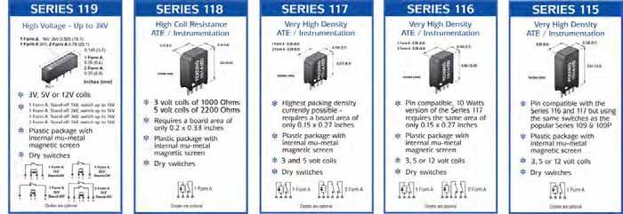
7 PICKERING SERIES 200 Surface Mount Reed Relays Including coaxial types for up to GHz New 3 Volt Version FEATURES SoftCenter construction Highest quality instrumentation grade switches Encapsulated in plastic package with internal mu-metal for side-by-side mounting without magnetic interaction Insulation greater than 10 ohms for Form A devices Dry and mercury wetted switches available Wide range of switch con gurations -, 1 Form B, 2 Form A and 1 Form C For R.F. or high speed digital applications, 0 or 7 ohms coaxial devices are available in the same small package 3,, and volt coils are standard, with or without internal diode 100% tested for dynamic contact The Series 200 is a complete range of surface mount reed relays. Both dry and mercury wetted switches are available in a wide range of configurations including coaxial types for RF up to GHz, or high speed digital switching with a step response time of less than 30ps. Please contact our technical department for supplementary RF data. The special high temperature plastic package will withstand the temperatures associated with Infra-red or vapour phase reflow soldering processes. A flexible inner encapsulant protects the sensitive glass/metal seals - this is a very big advantage over the more usual hard moulded package. Switch Ratings - Dry Switches, 10 watts at 200V, 1 watts at 200V, 10 watts at 00V Coaxial 0 (energize to make), 10 watts at 200V Coaxial 7 (energize to make), 10 watts at 200V 1 Form B (energize to break), 10 watts at 200V 1 Form C (change-over), 3 watts at 200V 2 Form A (energize to make), 10 watts at 200V Switch Ratings - Mercury Wetted Switches, 0 watts at 00V (Position insensitive), 30 watts at 30V 1.2 (0.6) 1.2 (0.6) PICKERING ELECTRONICS A - / 2 D PICKERING ELECTRONICS A - / 2 D 20.0 (0.79) UP PICKERING ELECTRONICS A-/6D 3.90 (0.14) 4.0mm max. 6.8 Max (0.27) 17.2 (0.68) UP PICKERING ELECTRONICS 200RF0-1-A-/2D Co-axial.8 (0.23) 6.0mm max. 6.8 Max (0.27) 17.2 (0.68) PICKERING ELECTRONICS B - / 2 D 2 Form A 1 Form B 22.0 (0.87).8 (0.23) 6.0mm max. 9.0 Max (0.3) High voltage Dry or Mercury 1.2 (0.6) 1.2 (0.6) 20.0 (0.79) PICKERING ELECTRONICS C-/7D UP PICKERING ELECTRONICS Clacton-on-Sea, England C-/7D 1 Form C Dry 3.90 (0.14) 4.0mm max. 6.8 Max (0.27) 17.2 (0.68).8 (0.23) 6.0mm max. 6.8 Max (0.27) 17.2 (0.68) 22.0 (0.87).8 (0.23) 6.0mm max. 9.0 Max (0.3) Dimensions in Millimetres (Inches in brackets) 200/06/09
8 Dry Reed - Series 200 switch s The contact s for each switch type are shown below: Sw. Switch No form Power switch current carry current switching volts Dry Relay - data and type numbers Special Features 1 A 1 Watts 0.7 Amp. 1.2 Amp. 200 General purpose 2 A or B 10 Watts 0. Amp. 1.2 Amp. 200 Low level 3 C 3 Watts 0.2 Amp. 1.2 Amp. 200 Change over 4 A 10 Watts 0. Amp. 1.2 Amp. 00 High Voltage Switch no.2 is particularly good for switching low currents and/or voltages. It is the ideal switch for Automatic Test Equipment where cold switching techniques are often used. Where higher power levels are involved, switch no.1 is a more suitable choice. Device description Type number (V) resist. (ohms) Contact resist. max. (initial) Package Number Pin configuration and dimensional data Dimensions in Millimetres (Inches in brackets). (Energize to make) Package Number 1 Schematic shown from top of relay Orientation spot printed on this corner (Coaxial) Package Number 2 Schematic shown from top of relay Orientation spot printed on this corner 2.0 (0.08) 6.8 (0.27) 1.0 pitch (0.04) 6.8 (0.27) 0.2 () 1.2 (0.6) PICKERING - England A - / 1 D 0.2 () 1.0 (0.04) 1.2 (0.6) 1.0 (0.04) PICKERING - England 200RF0-1-A- / 2D 1.0 (0.04) 1.0 (0.04) 0.0 () 3.90 (0.14) 4.0mm max. 1.0 (0.04) 0.40 (6) 3.90 (0.14) 4.0mm max. 1.0 (0.04) General Purpose Sw. No. 1 Low Level Switch No. 2 0 ohms coaxial Low Level Switch No. 2 7 ohms coaxial Low Level Switch No. 2 High Voltage Switch No. 4 1 Form C (change-over) Switch No. 3 1 Form B (energize to break) Low Level Switch No A-/1D A-/1D A-3/2D A-/2D A-/2D 200RF0-1-A-/2D 200RF0-1-A-/2D 200RF7-1-A-/2D 200RF7-1-A-/2D A-/4D A-/4D C-/3D C-/3D B-/2D B-/2D Form A (Energize to make) Package Number 3 Schematic shown from top of relay Orientation spot printed on this corner 1 Form B (Energize to break) Package Number 4 Schematic shown from top of relay Orientation spot printed on this corner 2.0 pitch (0.08) 6.8 (0.27) 4.0 (0.16) 6.8 (0.27) 0.2 () 0.2 () 1.2 (0.6) PICKERING - England A - / 2 D 1.0 (0.04) 1.0 (0.04) 1.2 (0.6) PICKERING - England B - / 2 D 1.0 (0.04) 1.0 (0.04) 0.0 () 1.0 (0.04) 0.0 () 1.0 (0.04).8 (0.23) 6.0mm max..8 (0.23) 6.0mm max. 2 Form A (energize to make) Low Level Switch No. 2 When an internal diode is required, the suffix D is added to the part number as shown in the table. If a diode is not required, the D suffix should be omitted. Mercury Reed - Series 200 switch s The contact s for each switch type are shown below: Sw. Switch No form Power A-/2D A-/2D switch current carry current 400 switching volts Special Features (Energize to make) Package Number Schematic shown from top of relay Orientation spot printed on this corner Mercury wetted versions this way up 4.0 (0.16) 9.0 (0.3) 0.2 () 20.0 (0.79) PICKERING - England A- / 6D UP 1.0 (0.04) 1.0 (0.04) 0.0 () 1.0 (0.04).8 (0.23) 6.0mm max. 6 A 0 Watts 2 Amp. 3 Amp. 00 Standard Mercury 8 A 30 Watts 0.7 Amp. 2 Amp. 30 Position Insensitive Mercury Relay - data and type numbers Device type Type Number voltage contact (initial) 1 Form C (Changeover) Package Number 6 Schematic shown from top of relay Orientation spot printed on this corner 2.0 pitch (0.08) 9.0 (0.3) 0.2 () 20.0 (0.79) PICKERING - England C - / 3 D 1.0 (0.04) 1.0 (0.04) 0.0 () 1.0 (0.04).8 (0.23) 6.0mm max. Switch No. 6 Position Insensitive Switch No A-/6D A-/6D A-/8D A-/8D Ohms 0.07 Ohms Ohms Ohms Mercury Relays With the exception of the position insensitive type, mercury relays should be mounted vertically in the direction of the arrow. When an internal diode is required, the suffix D is added to the part number as shown in the table. If a diode is not required, the D suffix should be omitted. Order Code The following example indicates data required to process your order promptly: A - / 2 D Series Number of reeds Switch form voltage Switch number (See table adjacent) if fitted (Omit if not required) Help!!! If you need any technical advice or help in any way, please telephone our Technical Sales Department. There is a limit to how much data we can put on a sales leaflet and we will always be pleased to discuss Pickering reed relays with you. Please ask us for a FREE evaluation sample
 3, and Volt coils are standard, with or without internal diode 100% tested for dynamic contact Ideal for Cable Testers, Mixed signal")
9 PICKERING SERIES 119 High Voltage Micro-SIL Reed Relays for up to 3kV FEATURES SoftCenter construction Highest quality instrumentation grade switches Small size Internal mu-metal magnetic One or two switches in a single package Form A or 2 Form A (energize to make) 3, and Volt coils are standard, with or without internal diode 100% tested for dynamic contact Ideal for Cable Testers, Mixed signal testers or other applications where High Voltage capability is required. The Pickering Series 119 is a new range of very small Single-in-Line Reed Relays intended for voltages very much higher than standard small SIL relays. The vacuumed, sputtered ruthenium reed switches have a superb low level performance also, which makes them an ideal choice where a wide range of signals are involved. The range is based on the long established Series 109P style of plastic package with an internal mu-metal magnetic which allows high packing density and are made using Pickering s SoftCenter construction. Four versions are available, all with either 3, or volt ope coils. The, 1kV version has a package and pin configuration compatible with the standard 109P type, i.e. 4 pins on 0.1 inches (3.8mm) pitch. These can be stacked side-by-side for maximum packing density. The other types have package lengths and pin configurations appropriate for their voltage s and the user will need to arrange suitable clearance distances around the parts., 1kV, 2kV 0.9 (1.1) 3kV, 2 Form A 0.79 (20.1) 0.14 (3.7) Clacton-on-Sea, England A-/1D PICKERING ELECTRONICS, 0.26 (6.6) 2 Form A, 0.3 (8.9) Dimensions in inches (millimetres in brackets) Switch Ratings - Dry switches Standing off 1kV, switching up to 1kV. Standing off 2kV, switching up to 1kV. Standing off 3kV, switching up to 1kV. 2 Form A (energize to make) Standing off 1kV, switching up to 1kV. Pickering SoftCenter Construction TYPICAL PICKERING CONSTRUCTION Internal mu-metal magnetic Bobbinless self supporting coil to maximise Soft inner to protect Hard outer Reed switch TYPICAL COMPETITOR S CONSTRUCTION Very hard moulding No mu-metal magnetic High magnetic interaction with adjacent relays winding supporting bobbin, wastes space and reduces 119/0/1

10 voltage - nominal 3V V V Must operate voltage - 2 º C 2.2V 3.7V 9V Dimensions in Inches (Millimetres in brackets). Must release voltage - min. at 2 º C 0.3V 0.V 1.2V - +/-10% at 2 º C.. Switch Type No.1-1kV - +/-10% at 2 º C.. Switch Type No.2-2kV - +/-10% at 2 º C.. Switch Type No.3-3kV 100 Ohms 20 Ohms 70 Ohms 7 Ohms 200 Ohms 00 Ohms 0 Ohms Ohms 400 Ohms - +/-10% at 2 º C. 2 Form A. Switch Type No.1. 1kV Stand-off Voltage, Switch No.1 - d.c. or a.c. peak 0 Ohms 100 Ohms 400 Ohms Volts Stand-off Voltage, Switch No.2 - d.c. or a.c. peak Stand-off Voltage, Switch No.3 - d.c. or a.c. peak Switching voltage, All types - max. d.c. or a.c. peak resistive Switching current, All types - max. Carry current, All types - max. Switching power, (VxI) All types - maximum Contact, All types - maximum initial Life expectancy - ops. typical (see note 1 below) Operate time - maximum, including bounce Release time - maximum, with diode suppression Insulation, minimum - switch to coil Insulation, minimum - across switch Capacitance, typical - closed switch to coil, Switch No.1 Capacitance, typical - closed switch to coil, Switch No.2 Capacitance, typical - closed switch to coil, Switch No.3 Capacitance - across open switch, typical, Switch No.1 (see note 3 below) Capacitance - across open switch, typical, Switch No.2 (see note 3 below) Capacitance - across open switch, typical, Switch No.3 (see note 3 below) 2000 Volts Volts Volts 0.7 Amps 1.2 Amps 10 Watts 170 m x10e ms 0.1 ms 10E (1T ) 10E (1T ) 2.pf 2.pf 2.0pf 0.1pF 0.1pF 0.0pF Ope temperature range Vibration - maximum -20 to +8 º C 20 G Shock - maximum 0 G Notes Note 1, Switching Voltage This high voltage is for RESISTIVE loads only. At these high voltages, even stray capacitance can generate very high current pulses, which can damage the contact plating causing welding of the. If there is capacitance in circuit, provision should be made to limit the surge, to within the current and power s of the relay. Note 2, Life expectancy The life of a reed relay depends upon the switch load and the end of life criteria. As an example, with an end of life contact specification of 1 ohm, switching low loads (10 V at 10mA resistive) or when cold switching, typical life will be around Million operations. At the maximum load (resistive), typical life will be 10 Million operations. In the event of abusive conditions, for example high currents due to capacitive inrushes, this figure will reduce considerably. Pickering will be pleased to perform life testing with any particular load condition. Note 3, Capacitance across open switch. This is measured with all other component leads connected to the guard terminal of the measuring bridge. The following example indicates data required to process your order promptly: A - / 1 D Series Number of reeds Switch form voltage Switch number Help!!! If you need any technical advice or help in any way, please telephone our Technical Sales Department or techsales@pickeringrelay.com. There is a limit to how much data we can put on a sales leaflet and we will always be pleased to discuss Pickering reed relays with you.
 Highest quality instrumentation grade switches Sputtered ruthenium switches rated at 10 Watts, 0. A or 1 Watts, 0.")
11 118-1-A-/2D ENGINEERING COMPONENTS PICKERING SERIES 118 High Resistance Single-in-Line reed relays Stacks on 0.2 x 0.33 inches pitch New 3 Volt Version FEATURES SoftCenter construction (see opposite) Highest quality instrumentation grade switches Sputtered ruthenium switches rated at 10 Watts, 0. A or 1 Watts, 0.7 A Plastic package with internal mu-metal magnetic They take up very little board area, conserving space Insulation greater than % tested for dynamic contact for guaranteed performance 0.32 nominal (8.13) 0.33 maximum (8.38) PICKERING 0.19 nominal (4.80) 0.20 maximum ( nominal (1.) 0.61 maximum (1.) The Pickering Series 118 is a range of very sensitive reed relays that are ideal for portable electronic instruments or other applications where low power consumption and a very small footprint is important. They have volt coils with a up to 2200 and the option of an internal diode. Two switch types are available. Switch type number 1 is better suited for general purpose applications. Switch type 2 is better suited to low level or 'cold' switching. Both types feature high quality, instrumentation grade switch contacts and require a board area of only 0.2 x 0.33 inches (.1 x 8.4 mm). These relays feature internal mu-metal magnetic s. Mu-metal has the advantage of a high permeability and low magnetic remanence and eliminates problems that would otherwise occur due to magnetic interaction. Relays of this size without magnetic ing would be totally un suit able for ap pli ca tions where dense packing is required. Initially, single pole versions only are available in this range but double pole versions will follow in the future. Internal mu-metal magnetic Bobbinless self supporting coil to maximise Internal mu-metal magnetic permitting high packing density without magnetic interaction Delicate glass/metal seal. Must be protected Former-less ope coil Instrumentation grade Soft inner to protect Dimensions in Inches (Millimetres in brackets) Pickering SoftCenter Construction TYPICAL PICKERING CONSTRUCTION Reed switch PICKERING A-/2D Actual size TYPICAL COMPETITOR S CONSTRUCTION Very hard moulding No mu-metal magnetic High magnetic interaction with adjacent relays winding Hard outer supporting bobbin, wastes space and reduces 118/0/13
12 voltage - nominal 3 V V Must operate voltage - 2 o C 2.2 V 3.7 V Must release voltage - min. at 2 o C 0.3 V 0. V - +/-10% at 2 o C. Switch Type No Switch Type No Switching voltage - max. d.c. or a.c. peak resistive Switching current - max. d.c. or a.c. peak resistive Carry current - max. d.c. or a.c. r.m.s. Switching power - maximum Contact - maximum initial Life expenctancy - ops. typical (see note 1 below) Switching voltage - max. d.c. or a.c. peak resistive Switching current - max. d.c. or a.c. peak resistive Carry current - max. d.c. or a.c. r.m.s. Switching power - maximum Contact - maximum initial Life expenctancy - ops. typical (see note 1 below) Operate time - maximum, including bounce Release time - maximum, with diode suppression Insulation - switch to coil, minimum Insulation - across switch, minimum Capacitance - closed switch to coil, typical (See note 2 below) Capacitance - across open switch, typical (Measured with other connections guarded) For other capacitance figures please contact our Technical Sales office. Ope temperature range Vibration - maximum Shock - maximum 200 V 0.7 Amps 1.2 Amps 1 Watts 0 m x10e6 200 V 0. Amps 1.2 Amps 10 Watts 0 m x10e6 0.6 ms 0.3 ms 10E 10E 3.0 pf 0.14 pf -20 to +80 o C 20 Gs 0 Gs Notes Note 1, Life expectancy The life of a reed relay depends upon the switch load and the end of life criteria. As an example, with an 'end of life' contact specification of 1 ohm, switching low loads (10 V at 10mA resistive) or when 'cold' switching, typical life will be around Million operations. At the maximum load (resistive), typical life will be 10 Million operations. In the event of abusive conditions, for example high currents due to capacitive inrushes, this figure will reduce considerably. Pickering will be pleased to perform life testing with any particular load condition. Note 2, Switch to coil capacitance Due to the asymmetrical internal construction of the relay, the capacitance to the coil from one switch connection is approximately half the capacitance of the other switch connection, pin 3 is lower. In some applications this feature may be used to advantage for example, in a multiplexer where it is desirable to minimize the capacitance of the common connection to maximize bandwidth. Dimensions in Inches (Millimetres in brackets) 0.60 (1.) 0.61 (1.) max. 0. (3.17) 0.32 (8.13 ) 0.33 (8.38) max. PICKERING A-/2D 0.06 (1.2) 0.1 (2.4) 0.1 (2.4) Series Number of reeds Switch form voltage Switch number (1 or 2 See table adjacent) Drawing approximately twice actual size (0.) 0.19 (4.8)0.20 (.08) max. (0.2) (0.) All dimensions are nominal unless specified A - / 2 D Internal Mu-metal Magnetic Screen The Series 118 relays are fitted with an internal mu-metal magnetic which permits side-by-side stacking on 0.2 inches pitch. For maximum efficiency of this, relays used in this way should all be mounted the same way round and with the coil supply of the same polarity. Help!! If you need any technical advice or other help, for example, any special tests that you would like carried out, please do not hesitate to contact our Technical Sales Department. We will always be pleased to discuss Pickering relays with you. Please ask us for a FREE evaluation sample ISO9001 Manufacture of Reed Relays FM 29036

13 PICKERING SERIES 117 Single-in-Line reed re lays 3 Watts switching - Very high packing density stacks on 0.1 x 0.27 inches pitch 2 Form A stacks on 0.1 x 0.40 inches pitch New 3 Volt Version FEATURES SoftCenter construction (see opposite) Highest quality instrumentation grade switches Plastic package with internal mu-metal magnetic They take up the minimum of board area, conserving board space Insulation greater than 10 3 or Volt coils with or without internal diode 100% tested for dynamic contact for guaranteed performance 0.26 nominal (6.60) 0.27 maximum (6.86) 2 Form A 0.39 nominal (9.90) 0.40 maximum (10.16) 0.14 nominal (3.70) 0.1 maximum (3.81) 0.37 nominal (9.2) 0.38 maximum (9.78) The Pickering Series 117 is a range of Single-in-Line relays intended for very high density ap pli ca tions such as A.T.E. switching matrices or multiplexers. They are available with either 1 or 2 Form A (energize to make) switches. Single switch versions require a board area of only 0.1 inches x 0.27 inches. This is one quarter of the board area of the industry standard 0.2 x 0.8 inches Single-in-Line packge. The very small size of these relays often makes it possible to in crease the functionality of existing designs without increasing the size of printed circuit boards. The Series 117 switch of 3 Watts, 0.2 A. is adequate for most instrumentation applications. If a higher is required, the Series 116, which is rated at 10 Watts, 0. A. should be considered. The relay footprint and pin configurations of the Series 116 are identical but the case height increases slightly to 0.49 inches. (. mm.) The relays feature an internal mu-metal magnetic. Mu-metal has the advantage of a high permeability and low magnetic remanence and eliminates problems that would otherwise occur due to magnetic interaction. Interaction is usu ally meas ured as a per cent age in crease in the voltage re quired to operate a relay when additional relays, stacked each side, are them selves operated. An uned de vice mount ed on this pitch would have an inter ac tion figure of around 40 percent. Relays of this size without magnetic ing would there fore be totally un suit able for ap pli ca tions where dense packing is required. 3 volt and volt coils are available with an optional Back E.M.F suppression diode. Hard outer Dimensions in Inches (Millimetres in brackets) Pickering SoftCenter Construction TYPICAL PICKERING CONSTRUCTION Internal mu-metal magnetic permitting high packing density without magnetic interaction Delicate glass/metal seal. Must be protected Internal mu-metal magnetic Bobbinless self supporting coil to maximise Former-less ope coil Instrumentation grade Soft inner to protect Reed switch PICKERING A-/2D Actual size PICKERING England A-/2D 2 Form A TYPICAL COMPETITOR S CONSTRUCTION Very hard moulding No mu-metal magnetic High magnetic interaction with adjacent relays winding supporting bobbin, wastes space and reduces 117/07/1
14 The in the Series 117 is suitable for low level or 'cold' switching. In accordance with Pickering convention, this switch is referred to as type number 2. There is no general purpose switch (type number 1) currently available in this series, but the type 2 is suitable for all applications if it is used within its specified s. This means that high inrush currents, particularly caused by capacitve loads must be avoided. Dimensions in Inches (Millimetres in brackets) 0.26 (6.60) 0.27 (6.86) max (9.90) 0.40 (10.16) max. Drawing approximately twice actual size 0.14 (3.70) 0.1 (3.81) max. voltage - nominal 3 V V Must operate voltage - maximum at 2 o C 2.2 V 3.7 V Must release voltage - minimum at 2 o C 0.3 V 0. V - +/-10% at 2 o C Form A - 20 Switching voltage - max. d.c. or a.c. peak resistive Switching current - max. d.c. or a.c. peak resistive Carry current - max. d.c. or a.c. r.m.s. Switching power - maximum Contact - maximum initial Life expenctancy - ops. typical (see note 1 below) Operate time - maximum, including bounce Release time - maximum, with diode suppression Insulation - switch to coil, minimum Insulation - across switch, minimum Capacitance - closed switch to coil, typical (See note 2 below) Capacitance - across open switch, typical (Measured with other connections guarded) For other capacitance figures please contact our Technical Sales office. Ope temperature range Vibration - maximum Shock - maximum 100 V 0.2 A 0. A 3 Watts 0 m 20x10E6 0.2 ms 0.1 ms 10E 10E 2.0 pf 0.14 pf -20 to +80 o C 20 Gs 0 Gs Notes Note 1, Life expectancy The life of a reed relay depends upon the switch load and the end of life criteria. As an example, with an 'end of life' contact specification of 1 ohm, switching low loads (10 volts at 10mA resistive) or when 'cold' switching, typical life will be around 20 Million operations. At the maximum load (resistive), typical life will be 10 Million operations. In the event of abusive conditions, for example high currents due to capacitive inrushes, this figure will reduce considerably. Pickering will be pleased to perform life testing with any particular load condition. Note 2, Switch to coil capacitance Due to the asymmetrical internal construction of the relay, the capacitance to the coil from one switch connection is approximately half the capacitance of the other switch connection, for the version pin 3 is lower. In some applications this feature may be used to advantage for example, in a multiplexer where it is desirable to minimize the capacitance of the common connection to maximize bandwidth (9.2) 0.38 (9.78) max. 0. (3.17) PICKERING A-/2D 0.06 (1.2) 0.06 (1.2) 0.06 (1.2) (0.38) PICKERING England A-/2D 0.06 (1.2) 0.06 (1.2) Important note: The spacing between pins 4 and is greater than between other pins NOTE¹ 0.06 (1.2) 0.07 (1.78) 0.06 (1.2) (0.38) (0.2) (0.) All dimensions are nominal unless specified View from below showing postion of round pins NOTE¹: Pin 3 is round with an outer diameter of 6 (0.4) NOTE²: Pins 4 and are round with an outer diameter of 6 (0.4) 2 Form A Important note: The spacing between pins 4 and is greater than between other pins Series Number of reeds Switch form voltage Switch number (Only Type 2 available) NOTE² A - / 2 D The Series 117 relays are fitted with an internal mu-metal magnetic which permits side-by-side stacking on 0.1 inches pitch. For maximum efficiency of this, relays used in this way should all be mounted the same way round and with the coil supply of the same polarity. Actual Size In this small area of only 2.16 x 1.2 inches (.48 x 3.0 cm), it is possible to construct an 8 x 8 matrix - 64, relays. Help!! If you need any technical advice or other help, for example, any special tests that you would like carried out, please do not hesitate to contact our Technical Sales Department. We will always be pleased to discuss Pickering relays with you. Please ask us for a FREE evaluation sample

 New 3 Volt Version The Pickering Series 116 is a range of Single-in-Line relays intended for very high density ap pli ca tions such as A.T.E. switching matrices or multiplexers.")
15 FEATURES SoftCenter construction (see opposite) Highest quality instrumentation grade switches Plastic package with internal mu-metal magnetic They take up the minimum of board area, conserving board space Insulation greater than 10 3, or Volt coils with optional internal diode 100% tested for dynamic contact for guaranteed performance PICKERING SERIES 116 Single-in-Line reed re lays 10 Watts switching - Very high packing density stacks on 0.1 x 0.27 inches pitch 2 Form A stacks on 0.1 x 0.40 inches pitch 0.26 nominal (6.60) 1 Form B 0.39 maximum (9.9) 0.14 nominal (3.70) 0.49 maximum (.6) New 3 Volt Version The Pickering Series 116 is a range of Single-in-Line relays intended for very high density ap pli ca tions such as A.T.E. switching matrices or multiplexers. They have a switch of 10 Watts, 0. A and are pin compatible with the Pickering Series 117 which have a lower power of 3 Watts and a lower profile height of 0.38 inches (9.6 mm). Switches have sputtered ruthenium contacts making them ideal for low level or cold switch ing applications. 1 or 2 pole, Form A (energize to make) versions are available. The single pole version uses the same switch and coil assembly as the Pickering Series 1. Single switch versions require a board area of only 0.1 inches x 0.27 inches. This is one quarter of the board area of the industry standard 0.2 x 0.8 inches Single-in-Line packge. The very small size of these relays often makes it possible to in crease the functionality of existing designs without increasing the size of printed circuit boards. The relays feature an internal mu-metal magnetic. Mu-metal has the advantage of a high permeability and low magnetic remanence and eliminates problems that would otherwise occur due to magnetic interaction. Interaction is usu ally meas ured as a per cent age in crease in the voltage re quired to operate a relay when additional relays, stacked each side, are them selves operated. An uned de vice mount ed on this pitch would have an inter ac tion figure of around 40 percent. Relays of this size without magnetic ing would there fore be totally un suit able for ap pli ca tions where dense packing is required. 3 volt, volt or volt coils are available. An internal Back E.M.F suppression diode is available as an option. Dimensions in Inches (Millimetres in brackets) Pickering SoftCenter Construction TYPICAL PICKERING CONSTRUCTION Internal mu-metal magnetic permitting high packing density without magnetic interaction Delicate glass/metal seal. Must be protected Internal mu-metal magnetic Bobbinless self supporting coil to maximise Former-less ope coil Instrumentation grade Soft inner to protect Hard outer Reed switch PICKERING A-/2D Actual size PICKERING England A-/2D 2 Form A TYPICAL COMPETITOR S CONSTRUCTION Very hard moulding No mu-metal magnetic High magnetic interaction with adjacent relays winding supporting bobbin, wastes space and reduces 116/07/1
16 The in the Series 116 is suitable for low level or 'cold' switching. In accordance with Pickering convention, this switch is referred to as type number 2. There is no general purpose switch (type number 1) currently available in this series, but the type 2 is suitable for all applications if it is used within its specified s. voltage - nominal 3 V V V Must operate voltage - 2 o C 2.2 V 3.7 V 9.0 V Must release voltage - min. at 2 o C 0.3 V 0. V 1.2 V - +/-10% at 2 o C Form A Switching voltage - max. d.c. or a.c. peak resistive Switching current - max. d.c. or a.c. peak resistive Carry current - max. d.c. or a.c. r.m.s. Switching power - maximum Contact - maximum initial Life expenctancy - ops. typical (see note 1 below) Operate time - maximum, including bounce Release time - maximum, with diode suppression Insulation - switch to coil, minimum Insulation - across switch, minimum Capacitance - closed switch to coil, typical (See note 2 below) Capacitance - across open switch, typical (Measured with other connections guarded) For other capacitance figures please contact our Technical Sales office. Ope temperature range Vibration - maximum Shock - maximum 200 V 0. A 0. A 10 Watts 0 m 20x10E6 0.3 ms 0.1 ms 10E 10E 2.1 pf 0.2 pf -20 to +80 o C 20 Gs 0 Gs Notes Note 1, Life expectancy The life of a reed relay depends upon the switch load and the end of life criteria. As an example, with an 'end of life' contact specification of 1 ohm, switching low loads (10 V at 10mA resistive) or when 'cold' switching, typical life will be around 20 Million operations. At the maximum load (resistive), typical life will be 10 Million operations. In the event of abusive conditions, for example high currents due to capacitive inrushes, this figure will reduce considerably. Pickering will be pleased to perform life testing with any particular load condition. Note 2, Switch to coil capacitance Due to the asymmetrical internal construction of the relay, the capacitance to the coil from one switch connection is approximately half the capacitance of the other switch connection, pin 3 is lower. In some applications this feature may be used to advantage for example, in a multiplexer where it is desirable to minimize the capacitance of the common connection to maximize bandwidth. Dimensions in Inches (Millimetres in brackets) 0.49 (.4) 0.49 (.6) max. 0. (3.17) 0.26 (6.60) 0.27 (6.86) max. PICKERING A-/2D 0.06 (1.2) 0.06 (1.2) 0.06 (1.2) (0.38) Important note: The spacing between pins 4 and is greater than between other pins NOTE¹ 0.39 (9.90) 0.40 (10.16) max. PICKERING England A-/2D 0.06 (1.2) 0.06 (1.2) 0.06 (1.2) 0.07 (1.78) 0.06 (1.2) (0.38) View from below showing postion of round pins Drawing approximately twice actual size 0.14 (3.70) 0.1 (3.81) max. (0.2) (0.) All dimensions are nominal NOTE¹: Pin 3 is round with an outer diameter of 7 (0.44) NOTE²: Pins 4 and are round with an outer diameter of 7 (0.44) 2 Form A Important note: The spacing between pins 4 and is greater than between other pins Series Number of reeds Switch form voltage Switch number (Only Type 2 available) NOTE² A - / 2 D The Series 116 relays are fitted with an internal mu-metal magnetic which permits side-by-side stacking on 0.1 inches pitch. For maximum efficiency of this, relays used in this way should all be mounted the same way round and with the coil supply of the same polarity. Actual Size In this small area of only 2.16 x 1.2 inches (.48 x 3.0 cm), it is possible to construct an 8 x 8 matrix - 64, relays. Help!! If you need any technical advice or other help, for example, any special tests that you would like carried out, please do not hesitate to contact our Technical Sales Department. We will always be pleased to discuss Pickering relays with you. Please ask us for a FREE evaluation sample
 Highest quality instrumentation grade switches Plastic package with internal mu-metal magnetic They take up the minimum of board area,")

17 PICKERING SERIES 11 Single-in-Line reed re lays 10 or 1 Watts switching - Very high packing density Stacks on 0.1 x 0.27 inches pitch FEATURES SoftCenter construction (see opposite) Highest quality instrumentation grade switches Plastic package with internal mu-metal magnetic They take up the minimum of board area, conserving board space Insulation greater than 10 3, or Volt coils with optional internal diode 100% tested for dynamic contact for guaranteed performance The Pickering Series 11 is a range of Single-in-Line relays intended for very high density ap pli ca tions such as A.T.E. switching matrices or multiplexers. They are pin compatible with the Pickering Series 116 and 117 but have a slightly higher profile. The /coil assemblies used in this series are the same as used in the long established and well proven, Series 109 and 109P. Two switch types are available. Both types have sputtered ruthenium contacts for long life and high reliability. Switch type number 1 is better suited for general purpose applications. It has a layer of copper beneath the ruthenium to help dissipate the heat from the contact area. This gives an improved current inrush handling ability. Switch type number 2 should be chosen for low level or 'cold' switching applications. The relays require a board area of only 0.1 inches x 0.27 inches. This is one quarter of the board area of the industry standard 0.2 x 0.8 inches Single-in-Line packge. The very small size of these relays often makes it possible to in crease the functionality of existing designs without increasing the size of printed circuit boards. The relays feature an internal mu-metal magnetic. Mu-metal has the advantage of a high permeability and low magnetic remanence and eliminates problems that would otherwise occur due to magnetic interaction. Relays of this size without magnetic ing would be totally un suit able for ap pli ca tions where dense packing is required. 3 volt, volt or volt coils are available. An internal Back E.M.F suppression diode is available as an option nominal (6.60) 0.14 nominal (3.70) TYPICAL PICKERING CONSTRUCTION Internal mu-metal magnetic permitting high packing density without magnetic interaction Delicate glass/metal seal. Must be protected Internal mu-metal magnetic Bobbinless self supporting coil to maximise Dimensions in Inches (Millimetres in brackets) Former-less ope coil Instrumentation grade Soft inner to protect Hard outer Reed switch 0.61 maximum (1.) PICKERING 11-1-A-/2D Very hard moulding Actual size New 3 Volt Version Pickering SoftCenter Construction TYPICAL COMPETITOR S CONSTRUCTION No mu-metal magnetic High magnetic interaction with adjacent relays winding supporting bobbin, wastes space and reduces 11/08/11
18 voltage - nominal 3 V V V Must operate voltage - 2 o C 2.2 V 3.7 V 9.0 V Must release voltage - min. at 2 o C 0.3 V 0. V 1.2 V Dimensions in Inches (Millimetres in brackets) 0.26 (6.60) 0.27 (6.86) max. - +/-10% at 2 o C Switching voltage - max. d.c. or a.c. peak resistive 200 V Switching current - max. d.c. or a.c. peak resistive 0.7 A Carry current - max. d.c. or a.c. r.m.s. 1.2 A Switching power - maximum 1 Watts Contact - maximum initial 0 m Life expenctancy - ops. typical (see note 1 below) x10e6 Switching voltage - max. d.c. or a.c. peak resistive 200 V Switching current - max. d.c. or a.c. peak resistive 0. A Carry current - max. d.c. or a.c. r.m.s. 1.2 A Switching power - maximum 10 Watts Contact - maximum initial 0 m 0.61 (1.) max. 0. (3.17) PICKERING 11-1-A-/2D 0.06 (1.2) 0.06 (1.2) 0.06 (1.2) 0.14 (3.7) 0.1 (3.8) max. Drawing approximately twice actual size (0.) (0.2) (0.38) All dimensions are nominal View from below showing postion of round pin NOTE: Pin 3 is round with an outer diameter of 7 (0.44) Life expenctancy - ops. typical (see note 1 below) Operate time - maximum, including bounce x10e6 0. ms Release time - maximum, with diode suppression Insulation - switch to coil, minimum Insulation - across switch, minimum Capacitance - closed switch to coil, typical (See note 2 below) Capacitance - across open switch, typical (Measured with other connections guarded) For other capacitance figures please contact our Technical Sales office. 0.2 ms 10E 10E 2.9 pf 0.14 pf Ope temperature range -20 to +80 o C Vibration - maximum 20 Gs Shock - maximum 0 Gs Notes Note 1, Life expectancy The life of a reed relay depends upon the switch load and the end of life criteria. As an example, with an 'end of life' contact specification of 1 ohm, switching low loads (10 volts at 10mA resistive) or when 'cold' switching, typical life will be around Million operations. At the maximum load (resistive), typical life will be 10 Million operations. In the event of abusive conditions, for example high currents due to capacitive inrushes, this figure will reduce considerably. Pickering will be pleased to perform life testing with any particular load condition. Note 2, Switch to coil capacitance Due to the asymmetrical internal construction of the relay, the capacitance to the coil from one switch connection is approximately half the capacitance of the other switch connection, pin 3 is lower. In some applications this feature may be used to advantage for example, in a multiplexer where it is desirable to minimize the capacitance of the common connection to maximize bandwidth. Series Number of reeds Switch form voltage Switch number (1 or 2 See table adjacent) A - / 2 D The Series 11 relays are fitted with an internal mu-metal magnetic which permits side-by-side stacking on 0.1 inches pitch. For maximum efficiency of this, relays used in this way should all be mounted the same way round and with the coil supply of the same polarity. Actual Size In this small area of only 2.16 x 1.2 inches (.48 x 3.0 cm), it is possible to construct an 8 x 8 matrix - 64, relays. Help!! If you need any technical advice or other help, for example, any special tests that you would like carried out, please do not hesitate to contact our Technical Sales Department. We will always be pleased to discuss Pickering relays with you. Please ask us for a FREE evaluation sample
 or Form B (energize to break) con gurations 3,, and Volt coils are standard, with or without internal diode 100% tested for dynamic contact The")

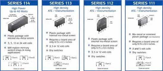
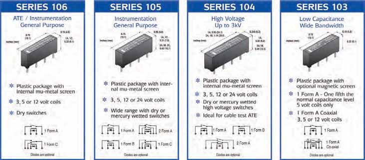
19 PICKERING SERIES 114 High Power Dry SIL reed relays FEATURES SoftCenter construction (see reverse) Highest quality instrumentation grade switches Small size Internal mu-metal magnetic One or two switches in a single package Form A (energize to make) or Form B (energize to break) con gurations 3,, and Volt coils are standard, with or without internal diode 100% tested for dynamic contact The Series 114 is a range of Single-In-Line reed relays intended for power levels that are beyond the capabilities of conventional dry SIL reed relays. The more usual dry relays are rated at 0. amps at 10 Watts. The Series 114 have a of 1 amp switching at up to 40 watts and will carry 2 amps. In many cases, this higher will allow them to be used as an alternative to mercury wetted reed relays. Unusually for high power relays, they feature sputtered ruthenium contacts instead of the more common electroplated rhodium or tungsten types. This makes them suitable for low level or dry switching also. They are able to switch a.c. mains voltages so are suitable for interfacing to larger electromechanical relays or contactors. It is important however, to surpress back EMFs from inductive loads. This is achievable by using an RC snubber, varistor or similar voltage limiting device. One or two Form A (energize to make) or One Form B (energize to break) configurations are available. The range features an internal mu-metal to minimize problems that would otherwise be experienced due to magnetic interaction when they are closely stacked. Form A versions may be stacked side-by-side. Due to the fact that the Form B types feature an internal biasing magnet, a gap of 0.4 inches minimum should be left between adjacent relays., 0.9 (.1) 1 Form B, 1.14 (29.0) 2 Form A, 1.14 (29.0) Dimensions in Inches (Millimetres in brackets) 0. (6.3), 0.32 (8.2) 1 Form B, 0.49 (.) 2 Form A, 0.49 (.) Switch Ratings - Dry switches 200 Volts dc or 0 Volts ac rms switching at up to 40 Watts. 00 Volts dc or ac peak stand-off. 2 Form A (energize to make) 200 Volts dc or 0 Volts ac rms switching at up to 40 Watts. 00 Volts dc or ac peak stand-off 1 Form B (energize to break) 200 Volts dc or 0 Volts ac rms switching at up to 40 Watts. 00 Volts dc or ac peak stand-off 114/06/10
20 Dry Reed Series 114 switch s The contact s for each switch type are shown below: Pin configuration and dimensional data Dimensions in Inches (Millimetres in brackets). Sw. No Switch form Power switch current carry current 1 A or B 40 Watts 1.0 Amp. 2.0 Amp. switching volts 200 vdc 0 vac rms stand-off volts (.1) 0. (6.22) 0.32 (8.13) (Energize to make) Dry Relays - Data and type num bers Device type Type number volts (ohms) contact (initial) 0.20 (.08) 0.20 (.08) 0.20 (.08) (0.1) (0.2) (0.1) (energize to make) 2 Form A (energize to make) A-3/1D A-/1D A-/1D A-/1D A-/1D A-/1D A-/1D Ohms 0.1 Ohms 0.1 Ohms 0.1 Ohms 1.14 (29) 0. (6.22) 0.49 (.) 2 Form A (Energize to make) 1 Form B (energize to break) B-/1D B-/1D B-/1D When an internal diode is required, the suffix D is added to the part number as shown in the table. If a diode is not required, the D suffix should be omitted (.08) 0.20 (.08) 0.20 (.08) 0.20 (.08) 0.20 (.08) (0.1) (0.2) (0.1) Pickering SoftCenter Construction 1.14 (29) 0. (6.22) 1 Form B (Energize to break) TYPICAL PICKERING CONSTRUCTION 0.49 (.) Internal mu-metal magnetic permitting high packing density without magnetic interaction Delicate glass/metal seal. Must be protected Internal mu-metal magnetic Former-less ope coil Instrumentation grade Soft inner to protect TYPICAL COMPETITOR S CONSTRUCTION Very hard moulding No mu-metal magnetic High magnetic interaction with adjacent relays 0.20 (.08) 0.20 (.08) 0.20 (.08) (0.1) (0.2) (0.1) Please note. Due to the presence of an internal biasing magnet, Form B relays have a higher level of magnetic interaction than Form A types. A space of 0.4 inches minimum should therefore be left between adjacent parts. Order Code The following example indicates data required to process your order promptly: A - / 1 D Series Bobbinless self supporting coil to maximise Hard outer Reed switch winding supporting bobbin, wastes space and reduces Number of reeds Switch form voltage Switch number (Only Type 1 available) if fi tted (Omit if not required) Help!!! If you need any technical advice or help in any way, please telephone our Technical Sales Department. There is a limit to how much data we can put on a sales leaflet and we will always be pleased to discuss Pickering reed relays with you. Please ask us for a FREE evaluation sample
21 PICKERING SERIES 113 Single-In-Line Reed Relays for stacking on 0.1 x 0. inches pitch giving SUPERB PACKING DENSITY FEATURES SoftCenter construction (see reverse) Highest quality instrumentation grade switches Form A versions have sputtered ruthenium contacts, ideal for Automatic Test Equipment Plastic package with internal mu-metal magnetic They take up very little area, conserving board space High insulation - greater than 10 ohms for Form A types and greater than ohms for Form C types 3, and Volt coils are standard, with or without internal diode, volt version has a coil of 00 ohms - drives directly from TTL logic 100% tested for dynamic contact The Pickering Series 113 is a range of magnetically ed single-in-line reed relays that require a board area of only 0.1 inches (3.8mm.) by 0. inches (.7mm.) The Form A (energize to make) versions retain the 10 Watts, 0. Amps associated with larger relays. The changeover version has a 3 Watts. These relays require less than half the board area of the more usual 0.2 x 0.8 inch devices and have a height of only 0.26 inches (6.6mm.) for the and 1 Form C types and 0.3 inches (8.9 mm.) for the 2 Form A type. The Series 113 is encapsulated in a plastic package using a very high resistivity resin to achieve an insulation greater than 10 ohms for the Form A types. The relay has an internal mu-metal which totally eliminates the risk of magnetic interaction problems. An uned device mounted on this pitch would have an interaction figure of around 40 percent. Relays of this size without magnetic ing would therefore be totally unsuitable for applications where dense packing is required. Pickering Series 113 have a typical interaction figure of percent. 3, and Volt coils are standard, with the option of an internal diode., Volt coils have a of 00 ohms and may be driven directly from TTL logic (.) 0.49 (.) PICKERING England A-/2D 1 Form C PICKERING England A-/2D 2 Form A 0.14 (3.7) 0.26 (6.6) 0.14 (3.7) 0.3 (8.9) Dimensions in Inches (Millimetres in brackets) New 3 Volt Version Switch Ratings - Dry switches, 10 watts at 200 V 2 Form A (energize to make), 10 watts at 200 V 1 Form C (change-over), 3 watts at 30 V 113/06/09


22 Series 113 switch s The contact s for each switch type are shown below: Sw. No data and type numbers When an internal diode is required, the suffix D is added to the part number as shown in the table. If a diode is not required, the D suffix should be omitted. Internal mu-metal magnetic Bobbinless self supporting coil to maximise Switch form Internal mu-metal magnetic permitting high packing density without magnetic interaction Delicate glass/metal seal. Must be protected Power switch current TYPICAL PICKERING CONSTRUCTION Former-less ope coil Instrumentation grade Soft inner to protect Hard outer Reed switch carry current switching volts Pickering SoftCenter Construction Very hard moulding contact (initial) 2 A 10 Watts 0. Amp 0. Amp Ohms 3 C 3 Watts 0.1 Amp. 0.1 Amp Ohms Switch number 2 is suitable for low level or "cold" switching applications. It is also a good general purpose "hot" switch as long as the maximum switching current specification is observed. There is no Switch number 1 available in this range at present. Switch type voltage Type Number Sw. No.2 Sw. No.2 (Special Pinout) 3 20 Ohms 00 Ohms 60 Ohms 00 Ohms 60 Ohms A-3/2D A-/2D A-/2D 113SP-1-A-/2D 113SP-1-A-/2D 2 Form A Sw. No.2 10 Ohms A-/2D 1 Form C Sw. No.3 10 Ohms C-/3D TYPICAL COMPETITOR S CONSTRUCTION No mu-metal magnetic High magnetic interaction with adjacent relays winding supporting bobbin, wastes space and reduces Pin configuration and dimensional data Dimensions in Inches (Millimetres in brackets) (6.6) 0. (3.3) 0.3 (8.9) 0. (3.3) 0.26 (6.6) 0. (3.3) 0.49 (.) (0.) (0.2) 0.1(2.4) 0.1(2.4) 0.1(2.4) (Energize to Make) 0.49 (.) (0.) (0.2) 0.08(2.0) 0.08(2.0) 0.08(2.0) 0.08(2.0) 0.08(2.0) 2 Form A (Energize to Make) 0.49 (.) 0.14 (3.7) (0.) (0.2) 0.08(2.0) 0.08(2.0) 0.16(4.0) 0.08(2.0)(0.) 0.14 (3.7) 0.14 (3.7) (0.) (0.) 1 Form C (Changeover) Schematic Schematic Schematic Special pin configuration for The standard device has 4 pins on 0.1 inches (2.4mm) pitch (see drawing above). This configuration makes it pin compatible with the Pickering Series 110, 111 and 1. A special pin configuration is also available with a pinout compatible with that of the 2 Form A type (see drawing above) The switch terminals are pins 1&6, the coil is Pins3&4 with pins 2& omitted, this version has the prefix 113SP. It is sometimes desirable to have a PCB that can be used for either or 2 Form A switching, this arrangement allows the use of a common board fitted with the appropriate relay (6.6) 0. (3.3) 0.49 (.) (0.2) 6(4.0) (4.0) 8(2.0)(0.) 01. Order Code The following example indicates data required to process your order promptly: A - / 2 D Series Number of reeds Switch form voltage Switch number (See table adjacent) if fi tted (Omit if not required) 113SP (Special Pinout) 0.14 (3.7) (0.) Schematic Dimensions in Inches (Millimetres in brackets) Help!!! If you need any technical advice or help in any way, please telephone our Technical Sales Department. There is a limit to how much data we can put on a sales leaflet and we will always be pleased to discuss Pickering reed relays with you. Please ask us for a FREE evaluation sample
 Highest quality instrumentation grade switches Ideal for high density card based systems and Automatic Test")

23 PICKERING SERIES 1 Single-in-Line Reed Relays for stacking on 0.1 x 0.4 inches pitch giving SUPERB PACKING DENSITY FEATURES SoftCenter construction (see reverse) Highest quality instrumentation grade switches Ideal for high density card based systems and Automatic Test Equipment Plastic package with internal mu-metal magnetic They take up the minimum of board area, conserving board space Insulation greater than 10 ohms 3, and Volt coils are standard, with or without internal diode Volt coils of 00 ohms may be driven directly from TTL logic 100% tested for dynamic contact The Pickering Series 1 is a range of magnetically ed single-in-line reed relays that require a board area of only 0.1 inches (3.8mm.) by 0.4 inches (10mm.) while retaining the 10 Watts, 0. Amps associated with larger relays. This small footprint is achieved by mounting the diagonally within the package. These relays require around one third the board area of the more usual 0.2 x 0.8 inch devices and the height of only 0.43 inches (11mm.) is suitable for high density card based systems such as VME, VXI, Compact PCI, and PXI. The high quality, sputtered ruthenium switch contacts also makes them ideal for Automatic Test Equipment. The Series 1 is encapsulated in a plastic package using a very high resistivity resin to achieve an insulation greater than 10 ohms. The relay has an internal mumetal which totally eliminates the risk of magnetic interaction problems. An uned device mounted on this pitch would have an interaction figure of around 40 percent. Relays of this size without magnetic ing would therefore be totally unsuitable for applications where dense packing is required. Pickering Series 1 have a typical interaction figure of percent. 3, and Volt coils are standard, with the option of an internal diode. Volt coils have a of 00 ohms and may be driven directly from TTL logic. Key: 0.39 (10) 0.14 (3.7) 0.43 (11.0) 0.1 (2.4) pin spacing Dimensions in Inches (Millimetres in brackets) 30% 20% Percentage Interaction (change in operate voltage) 10% P P Uned Other Uned 0.2 inch relays Internal mu-metal Package Width (inches) New 3 Volt Version Pickering relays Complete mu-metal can 1/06/09
24 Series 1 switch s The contact s for each switch type are shown below: contact Power Sw. No Switch form switch carry switching current current volts (initial) 2 A 10 Watts 0. Amp. 0. Amp Ohms The Following actual size example illustrates the relative packing densities of standard 0.2 x 0.8 inch SIL relays compared with Pickering Series 108, 109, and 1 reed relays when packed into an area of 1.2 x 2.4 inches. Important: Pickering SIL relays feature mu-metal magnetic s, uned relays are unsuitable for dense packing in this way. Switch number 2 is suitable for low level or "cold" switching applications. It is also a good general purpose "hot" switch as long as the maximum switching current specification is observed. There is no Switch number 1 available in this range at present. data and type numbers Switch type voltage Type Number Sw. No Ohms 00 Ohms 70 Ohms 1-1-A-3/2D 1-1-A-/2D 1-1-A-/2D When an internal diode is required, the suffix D is added to the part number as shown in the table. If a diode is not required, the D suffix should be omitted. 18 S S Pickering SoftCenter Construction TYPICAL PICKERING CONSTRUCTION TYPICAL COMPETITOR S CONSTRUCTION Internal mu-metal magnetic Soft inner to protect Very hard moulding No mu-metal magnetic High magnetic interaction with adjacent relays Using standard 0.2 x 0.8 inch relays in this PCB area you can fit 18 Relays Using PICKERING Series 108 relays in this PCB area you can fit Relays Bobbinless self supporting coil to maximise Pin configuration and dimensional data Dimensions in Inches (Millimetres in brackets) (10) Hard outer Reed switch winding supporting bobbin, wastes space and reduces 32 S Using PICKERING Series 109 relays in this PCB area you can fit 32 Relays 48 S Using PICKERING Series 1 relays in this PCB area you can fit 48 Relays 0.43 (11.0) 0. (3.3) PICKERING ENGLAND PICKERING E n g l a n d 1-1-A- / 2D 0.1 (2.4) pin spacing (0.) 0.14 (3.7) (0.) (0.2) Schematic If Packing Density Is Your Problem, Use Pickering Series 1 Order Code The following example indicates data required to process your order promptly: A - / 2 D Series Number of reeds Switch form voltage Switch number (Only Type 2 available) if fi tted (Omit if not required) Help!!! If you need any technical advice or help in any way, please telephone our Technical Sales Department. There is a limit to how much data we can put on a sales leaflet and we will always be pleased to discuss Pickering reed relays with you. Please ask us for a FREE evaluation sample
 Highest quality instrumentation grade switches Mu-metal magnetic ing Two package styles")
25 PICKERING SERIES 111 Pico-SIL Reed Relays Including coaxial types for up to 1. GHz for stacking on 0.1 x 0.4 inches pitch giving SUPERB PACKING DENSITY New 3 Volt Version FEATURES SoftCenter construction (see opposite) Highest quality instrumentation grade switches Mu-metal magnetic ing Two package styles - Mu-metal package or Plastic package with internal mu-metal magnetic They take up the minimum of board area, conserving board space Insulation greater than 10 ohms 3 or Volt coils with or without internal diode 100% tested for dynamic contact The Pickering Series 111 is a range of magnetically ed single-in-line reed relays that stack on 0.1 inches by 0.4 inches pitch. They have an identical footprint to the Series 110 and 1 but the height is reduced to only 0.26 inches (6.6mm). The switch of 3 Watts is adequate for most instrumentation applications. If a higher power is required, please look at our Series 110 or 1 which have a 10 Watts and an identical pin-out. The range also includes the type 111RF, a 0 ohms coaxial device suitable for use up to 1.GHz. These relays require around one third the board area of the more usual 0.2 x 0.8 inch devices and are ideal for high density applications. Two package styles are available: The type 111 is encapsulated in a mu-metal can. The coaxial version, type 111RF, is also available in this package style. The type 111P is encapsulated in a plastic package and features an internal mu-metal. An internal diode is an option in both types. Magnetic ing is essential to avoid magnetic interaction problems. Interaction is usually measured as a percentage increase in the voltage required to operate a relay when two additional relays, stacked one each side, are themselves operated. An uned device mounted on this pitch would have an interaction figure of around 40 %. Relays of this size would therefore be totally unsuitable for applications where dense packing is required. Pickering Series 111 have an interaction figure of around 1 percent. Internal mu-metal magnetic Key: Type 111 & 111RF Mu-metal package 0.39 (10) Bobbinless self supporting coil to maximise P I C K E R I N G Pico - SIL Relay 0.14 (3.7) 0.26 (6.6) 0.1 (2.4) pin spacing 30% 20% Percentage Interaction (change in operate voltage) 10% Type 111P Plastic package with internal mu-metal 0.39 (10) PICKERING England 111P-1-A-/1D 0.1 (2.4) pin spacing Dimensions in Inches (Millimetres in brackets) P P Uned Soft inner to protect Hard outer Other Uned 0.2 inch relays 107 Very hard moulding Internal mu-metal Package Width (inches) 0.14 (3.7) Pickering relays 0.26 (6.6) Pickering SoftCenter Construction TYPICAL PICKERING CONSTRUCTION Reed switch TYPICAL COMPETITOR S CONSTRUCTION No mu-metal magnetic High magnetic interaction with adjacent relays winding supporting bobbin, wastes space and reduces Complete mu-metal can 111/06/09
26 Series 111 switch s The contact s for each switch type are shown below: contact Power Sw. No Switch form switch carry switching current current volts (initial) 1 A 3 Watts 0.2 Amp. 0. Amp Ohms data and type numbers The Following actual size example illustrates the relative packing densities of standard 0.2 x 0.8 inch SIL relays compared with Pickering Series 108, 109, 110 and 111 reed relays when packed into an area of 1.2 x 2.4 inches. Important: Pickering SIL relays feature mu-metal magnetic s, uned relays are unsuitable for dense packing in this way. Switch type voltage Package Style Type Number Coaxial When an internal diode is required, the suffix D is added to the part number as shown in the table. If a diode is not required, the D suffix should be omitted. Pin configuration and dimensional data Dimensions in Inches (Millimetres in brackets). Type 111 Mu-metal package 0.26 (6.6) (3.3) 0.39 (10.0) PICKERING Pico-SIL 200 Ohms 00 Ohms 200 Ohms 400 Ohms (0.) 4 Pins on 0.1 inches (2.4mm) pitch 0.14 (3.7) Mu-metal Plastic with internal (0.) (0.2) A-3/1D A-/1D 111P-1-A-3/1D 111P-1-A-/1D 200 Ohms Mu-metal 111RF-1-A-/1D Energize to make 18 S Using standard 0.2 x 0.8 inch relays in this PCB area you can fit 18 Relays S Using PICKERING Series 108 relays in this PCB area you can fit Relays Type 111P Plastic package with internal mu-metal 0.26 (6.6) 0. (3.3) Type 111RF Mu-metal package 0.39 (10.0) PICKERING England 111P A -/1D PICKERING Pico-SIL (0.) 4 Pins on 0.1 inches (2.4mm) pitch 0.39 (10.0) 0.26 (6.6) 0. (3.3) (0.) 6 Pins on 0.06 inches (1.mm) pitch 0.14 (3.7) 0.14 (3.7) (0.) (0.2) (0.2) Energize to make (0.) Energize to make 32 S Using PICKERING Series 109 relays in this PCB area you can fit 32 Relays If Packing Density Is Your Problem, Use Pickering Series 110 or 111 Order Code The following example indicates data required to process your order promptly: A - / 1 D Series Number of reeds Switch form voltage Switch number (Only Type 1 available) if fitted (Omit if not required) 48 S Using PICKERING Series 110 or 111 relays in this PCB area you can fit 48 Relays Help!!! If you need any technical advice or help in any way, please telephone our Technical Sales Department. There is a limit to how much data we can put on a sales leaflet and we will always be pleased to discuss Pickering reed relays with you. Please ask us for a FREE evaluation sample
 Highest quality instrumentation grade switches Plastic package with internal mu-metal")
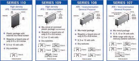
27 PICKERING SERIES 110 V-SIL Reed Relays for stacking on 0.1 x 0.4 inches pitch giving SUPERB PACKING DENSITY New 3 Volt Version FEATURES SoftCenter construction (see reverse) Highest quality instrumentation grade switches Plastic package with internal mu-metal magnetic They take up the minimum of board area, conserving board space Insulation greater than 10 ohms 3, and Volt coils are standard, with or without internal diode Volt coils of 00 ohms may be driven directly from TTL logic 100% tested for dynamic contact The Pickering Series 110 V-SIL (vertical single-in-line) is a range of magnetically ed single-in-line reed relays that stack on 0.1 inches by 0.4 inches pitch. The switches in this range are mounted vertically within the package, this allows the use of the same switch types as would normally be found in relays requiring a very much larger board area. In this way, a 10 Watt switch power is achieved. Two types of Form A (energize to make) switches are available, a general purpose version and a type suitable for low level or cold switching applications. These relays require around one third the board area of the more usual 0.2 x 0.8 inch devices. These are your idea choice for high density applications such as A.T.E. switching matrices or where very little board area is available. If a lower profile device is required, look at the Series 111, which has an identical pin-out but a height of only 0.26 inches. The Series 110 is encapsulated in a plastic package using a very high resistivity resin. The relay has an internal mumetal which totally eliminates the risk of magnetic interaction problems. An uned device mounted on this pitch would have an interaction figure of around 40 percent. Relays of this size without magnetic ing would therefore be totally unsuitable for applications where dense packing is required. Pickering Series 110 have a typical interaction figure of percent. 3, and Volt coils are standard, with the option of an internal diode. Volt coils have a of 00 ohms and may be driven directly from TTL logic. Key: 30% 20% Percentage Interaction (change in operate voltage) 10% (10) PICKERING ENGLAND 0.14 (3.7) 0.60 (1.2) 0.1 (2.4) pin spacing Dimensions in Inches (Millimetres in brackets) 109P P Uned Other Uned 0.2 inch relays Internal mu-metal Package Width (inches) Pickering relays Complete mu-metal can 110/06/09
28 Series 110 switch s The contact s for each switch type are shown below: Sw. No Switch form contact Power switch carry switching current current volts (initial) 1 A 10 Watts 0. Amp. 1.2 Amp Ohms 2 A 10 Watts 0. Amp. 1.2 Amp Ohms data and type numbers Switch type voltage Type Number Switch No.1 Switch No Ohms Ohms 20 ohms 00 Ohms Ohms A-/1D A-/1D A-3/2D A-/2D A-/2D When an internal diode is required, the suffix D is added to the part number as shown in the table. If a diode is not required, the D suffix should be omitted. Pickering SoftCenter Construction The Following actual size example illustrates the relative packing densities of standard 0.2 x 0.8 inch SIL relays compared with Pickering Series 108, 109, 110 and 111 reed relays when packed into an area of 1.2 x 2.4 inches. Important: Pickering SIL relays feature mu-metal magnetic s, uned relays are unsuitable for dense packing in this way. 18 S S TYPICAL PICKERING CONSTRUCTION Internal mu-metal magnetic permitting high packing density without magnetic interaction Using standard 0.2 x 0.8 inch relays in this PCB area you can fit 18 Relays Using PICKERING Series 108 relays in this PCB area you can fit Relays Delicate glass/metal seal. Must be protected Internal mu-metal magnetic Former-less ope coil Instrumentation grade Soft inner to protect TYPICAL COMPETITOR S CONSTRUCTION Very hard moulding No mu-metal magnetic High magnetic interaction with adjacent relays 32 S 48 S Bobbinless self supporting coil to maximise Pin configuration and dimensional data Dimensions in Inches (Millimetres in brackets) (10) 0.1 (2.4) pin spacing Hard outer Reed switch 0.14 (3.7) 0.60 (1) Schematic winding supporting bobbin, wastes space and reduces Using PICKERING Series 109 relays in this PCB area you can fit 32 Relays If Packing Density Is Your Problem, Use Pickering Series 110 or 111 Order Code The following example indicates data required to process your order promptly: A - / 2 D Series Number of reeds Switch form voltage Switch number (1 or 2 See table adjacent) if fi tted (Omit if not required) Using PICKERING Series 110 or 111 relays in this PCB area you can fit 48 Relays Help!!! If you need any technical advice or help in any way, please telephone our Technical Sales Department. There is a limit to how much data we can put on a sales leaflet and we will always be pleased to discuss Pickering reed relays with you. Please ask us for a FREE evaluation sample
 Highest quality instrumentation grade switches (energise to make) 2 Form A (energise to make) 1 Form B (energise to")
29 FEATURES PICKERING SERIES 109 Micro-SIL Reed Relays Including coaxial types for stacking on 0.1 x 0.6 inches pitch giving SUPERB PACKING DENSITY SoftCenter construction (see opposite) Highest quality instrumentation grade switches (energise to make) 2 Form A (energise to make) 1 Form B (energise to break) 1 Form C (changeover) Coaxial 0 Ohms impedance (energise to make) Coaxial 7 Ohms impedance (energise to make) Insulation greater than 10 ohms 3, and Volt coils are standard, with or without internal diode The mu-metal packaged Series 109 and 109RF and the plastic packaged Series 109P and Series 109PH, are magnetically ed single-in-line reed relays that stack on 0.1 inches x 0.6 inches pitch. The adjacent column gives further details of the device types available. These relays require little more than half the board area of the more usual 0.2 x 0.8 inch devices, this allows around 80 percent more relays onto your board. These are the ideal choice for high density applications such as A.T.E. switching matrices or where very little board area is available. Mu-metal, due to its high permeability and low magnetic remanance is used to provide magnetic ing. This eliminates problems that would otherwise occur due to magnetic interaction. Interaction is usually measured as a percentage increase in the voltage required to operate a relay when two additional relays, stacked one each side, are themselves operated. An uned device mounted on this pitch would have an interaction figure of around 40 percent. Relays of this size without magnetic ing would therefore be totally unsuitable for applications where dense packing is required. Pickering Series 109 and 109RF have a typical interaction figure of 1 percent. Series 109P and 109PH have a typical figure of 3 percent. Two types of Form A (energize to make) switches are available, a general purpose switch (switch no.1) and a vacuum sputtered ruthenium switch (switch no.2) which is ideal for low level or cold switching applications. volt coils normally have a of 00 ohms and volt coils are ohms. A sensitive single pole volt device with a ohms coil is also available. Internal back E.M.F. clamping diodes are an option for all types. The small size of these relays often makes it possible to increase the functionality of existing designs without increasing the size of printed circuit boards. Description of Device Types See reverse side of data sheet for dimensional details. Series 109, 2 Form A, 1 Form B, 1 Form C Similar in construction to the Pickering Series 107 and Series 108. These patented devices are encapsulated in mu-metal cans using very high resistivity resins. Series 109RF Coaxial Coaxial relays in mu-metal cans. They are available with a characteristic impedance of either 0 or 7 ohms. For R.F. up to 2GHz, telecoms, video or high speed digital switching up to 00 Mbits/sec. Contact technical sales office for further data. Series 109P, 1 Form C The electrical specification and dimensions are identical to the Series 109. They are encapsulated using the same resins within a plastic package which features an internal mumetal magnetic. Series 109PH The electrical specification is again identical but the mumetal ed plastic package is slightly different having an increased stand-off from the printed circuit board. Pickering SoftCenter Construction TYPICAL PICKERING CONSTRUCTION Internal mu-metal magnetic Bobbinless self supporting coil to maximise Soft inner to protect Hard outer Reed switch TYPICAL COMPETITOR S CONSTRUCTION Very hard moulding No mu-metal magnetic High magnetic interaction with adjacent relays winding supporting bobbin, wastes space and reduces 109/06/10
30 Series 109 switch s The contact s for each switch type are shown below: Sw. No Switch form Power switch current Device Package data and type numbers Type Number carry current switching volts 1 A 10 Watts 0. Amp. 1.2 Amp A 10 Watts 0. Amp. 1.2 Amp C 3 Watts 0.1 Amp. 0.1 Amp. 30 Switch no.1 is intended for general pupose use. Switch no.2 is intended for switching low levels. It is the ideal switch for A.T.E. systems where cold switching techniques are often used. Special high sensitivity volt model Standard volt coils have a of 00 ohms. A special model is available featuring a ohms, volt coil. This type is identified by a letter L in the part number, signifying low coil power, (see table below). type Style Switch No. 1 1 Switch No A-/1D A-L/1D A-/1D A-3/2D A-/2D A-L/2D A-/2D voltage contact (initial) When an internal diode is required, the suffix D is added to the part number as shown in the table. If a diode is not required, the D suffix should be omitted Ohms 0.1 Ohms 0.1 Ohms 0. Ohms 0. Ohms 0. Ohms 0. Ohms 1 Form B Switch No B-/2D Ohms 1 Form C 2 Form A Switch No Ohms Coaxial Switch No. 1 0 Ohms Coaxial Switch No. 2 7 Ohms Coaxial Switch No. 1 7 Ohms Coaxial Switch No. 2 Switch No. 1 6 Switch No Form C C-3/3D C-/3D A-/2D A-/2D 109RF0-1-A-/1D 109RF0-1-A-/1D 109RF0-1-A-3/2D 109RF0-1-A-/2D 109RF0-1-A-/2D 109RF7-1-A-/1D 109RF7-1-A-/1D 109RF7-1-A-/2D 109RF7-1-A-/2D 109P-1-A-/1D 109P-1-A-L/1D 109P-1-A-/1D 109P-1-A-3/2D 109P-1-A-/2D 109P-1-A-L/2D 109P-1-A-/2D 109P-1-C-3/3D 109P-1-C-/3D Ohms 0.2 Ohms 0.14 Ohms 0.14 Ohms 0.1 Ohms 0.1 Ohms 0. Ohms 0. Ohms 0. Ohms 0.1 Ohms 0.1 Ohms 0. Ohms 0. Ohms 0.1 Ohms 0.1 Ohms 0.1 Ohms 0. Ohms 0. Ohms 0. Ohms 0. Ohms 0.2 Ohms 0.2 Ohms Switch life The life of a reed relay will depend upon the switch load and the end of life criteria. As an example, with an end of life contact specification of 0. ohms, switching low loads (10 volts at 10mA resistive) or when cold switching, typical life will be Million operations. At the maximum load of 10 Watts (resistive), typical life will be 10 Million operations. In the event of abusive conditions, for example high currents due to capacitive inrushes, this figure will reduce considerably. Switch type number /1 is the prefered option where higher currents are involved, switch type number /2 is prefered for low level or cold switching. Pickering will be pleased to perform life testing with any particular load condition, do not hesitate to contact our Engineering Department. Pin configuration and dimensional data Dimensions in Inches (Millimetres in brackets). Package Style 1 Mu-metal Package A-? Package Style 2 Mu-metal Package B-? Package Style 3 Mu-metal Package A-? Package Style 4 Mu-metal Package 109RF0-1-A-? 109RF7-1-A-? For performance data of coaxial versions, please contact Pickering technical department Package Style Mu-metal Package C-? Package Style 6 Standard Plastic Package (Internal Mu-metal Screen) 109P-1-A-? Package Style 7 Standard Plastic Package (Internal Mu-metal Screen) 109P-1-C-? Energize to make 1 Form B Energize to break 2 Form A Energize to make Coaxial Energize to make Energize to make Order Code The following example indicates data required to process your order promptly: A - / 2 D 1 Form C Changeover 1 Form C Changeover Alternative pin configurations Alternative pin configurations are available, for example, relays with pins on 0.1 inches (2.4mm) pitch to enable insertion into standard SIL sockets. Please contact our technical sales office for further information Series Number of reeds Switch form voltage Switch number (1 or 2 See table adjacent) if fitted (Omit if not required) Please ask us for a FREE evaluation sample
31 PICKERING SERIES 108 Micro-SIL Reed Relays for stacking on 0.1 x 0.8 inches pitch New 3 Volt Version FEATURES SoftCenter construction (see opposite) Highest quality instrumentation grade switches Encapsulated in a mu-metal can Insulation greater than 10 ohms for Form A devices Dry switches available in, 2 Form A and 1 Form C con gurations. 2 Form A types require the same board area as 3, and Volt coils are standard, with or without internal diode Volt coils are 00 ohms and may be driven directly from TTL logic 100% tested for dynamic contact 0.79 (20.1) P I C K E R I N G Micro-SIL Relay 0.14 (3.7), 1 Form C, 0.26 (6.6) 2 Form A, 1 Form B, 0.3 (8.9) The Pickering Series 108 is a range of magnetically ed single-in-line reed relays that stack on 0.1 inches (3.8mm) pitch, resulting in a 2 percent saving in board space over 0.2 inch (.08mm) wide relays. This means that it is possible to pack 33 percent more relays into the same board area. Their small size, superb contact stability and ultra high insulation, greater than 10 ohms for Form A devices, make these relays a popular choice for high quality instrumentation. The device is encapsulated in a mu-metal can using a very high resistivity resin. Mu-metal is used rather than steel because of both its very high permeability and its low magnetic remanance. This construction totally eliminates the risk of magnetic interaction problems. Magnetic interaction is usually measured as a percentage increase in the voltage required to operate a relay when two additional relays, stacked one each side, are themselves operated. An uned device mounted on this pitch would have an interaction figure of around 40 percent, it would therefore be totally unsuitable for applications where relays are to be packed densely. Pickering Series 108 have a typical interaction figure of only 1 percent. Dry switches are available in 1 or 2 Form A (energize to make) and 1 Form C (change-over) configurations. 3, and Volt coils are available, Volt coils have a of 00 Ohms and may therefore be driven directly from TTL logic. Dimensions in Inches (Millimetres in brackets) Switch Ratings, 10 watts at 200V 2 Form A (energize to make), 10 watts at 200V 1 Form C (change-over), 3 watts at 200V 30% 20% Percentage Interaction (change in operate voltage) 10% P P Other Uned 0.2 inch relays Package Width (inches) Pickering relays Key: Uned Internal mu-metal Complete mu-metal can 108/06/09
32 Series 108 switch s The contact s for each switch type are shown below: Sw. Switch No form Power switch current carry current data and type numbers switching volts Special Features 1 A 10 Watts 0. Amp. 1.2 Amp. 200 General purpose 2 A 10 Watts 0. Amp. 1.2 Amp. 200 Low level 3 C 3 Watts 0.2 Amp. 1.2 Amp. 200 Change over Switch no.2 is particularly good for switching low currents and/or voltages. It is the ideal switch for Automatic Test Equipment where cold switching techniques are often used. Where higher power levels are involved, switch no.1 is a more suitable choice. Device type General Purpose Switch No. 1 Low Level Switch No. 2 1 Form C (change-over) Switch No. 3 2 Form A (energize to make) General Purpose Switch No. 1 2 Form A (energize to make) Low Level Switch No. 2 Type Number A-/1D A-/1D A-3/2D A-/2D A-/2D C-/3D C-/3D A-/1D A-/1D A-/2D A-/2D voltage contact (initial) When an internal diode is required, the suffix D is added to the part number as shown in the table. If a diode is not required, the D suffix should be omitted Ohms 0.1 Ohms 0. Ohms 0. Ohms 0. Ohms 0.2 Ohms 0.2 Ohms 0.17 Ohms 0.17 Ohms 0.1 Ohms 0.1 Ohms Pickering SoftCenter Construction TYPICAL PICKERING CONSTRUCTION Pin configuration and dimensional data Dimensions in Inches (Millimetres in brackets) (3.7) 0. (3.3) 0.26 (3.7) 0. (3.3) 0.3 (8.9) 0.20 (.08) 0.10 (2.4) 0.10 (2.4) 0.79 (20.0) PICKERING ELECTRONICS CLACTON-ON-SEA. ESSEX. ENGLAND (.08) 0.79 (20.0) 0.20 (.08) 0.20 (.08) PICKERING ELECTRONICS CLACTON-ON-SEA. ESSEX. ENGLAND (20.0) 0.20 (.08) PICKERING ELECTRONICS CLACTON-ON-SEA. ESSEX. ENGLAND. (0.08) (0.08) 0.14 (3.7) 0.14 (3.7) 0.14 (3.7) (0.08) (0.) (0.) (0.08) (0.08) (Energize to make) Form C (Changeover) Internal mu-metal magnetic permitting high packing density without magnetic interaction 0. (3.3) 0.10 (2.4) 0.10 (2.4) 0.20 (.08) 0.10 (2.4) 0.10 (2.4) (0.08) (0.) Form A (Energize to make) Delicate glass/metal seal. Must be protected Internal mu-metal magnetic Bobbinless self supporting coil to maximise Former-less ope coil Instrumentation grade Soft inner to protect Hard outer Reed switch TYPICAL COMPETITOR S CONSTRUCTION Very hard moulding No mu-metal magnetic High magnetic interaction with adjacent relays winding supporting bobbin, wastes space and reduces Order Code The following example indicates data required to process your order promptly: A - / 2 D Series Number of reeds Switch form voltage Switch number (See table adjacent) if fi tted (Omit if not required) Help!!! If you need any technical advice or help in any way, please telephone our Technical Sales Department. There is a limit to how much data we can put on a sales leaflet and we will always be pleased to discuss Pickering reed relays with you. Please ask us for a FREE evaluation sample
 Highest quality instrumentation grade switches Encapsulated in patented mu-metal can Insulation greater than 10 ohms")
33 PICKERING SERIES 107 Mini-SIL Reed Relays for stacking on 0.2 inches pitch New 3 Volt Version FEATURES SoftCenter construction (see opposite) Highest quality instrumentation grade switches Encapsulated in patented mu-metal can Insulation greater than 10 ohms for Form A devices Dry and mercury wetted switches available Wide range of switch con gurations -, 1 Form B, 2 Form A, 1 Form C, and 2 Form C, see adjacent column For R.F. or high speed digital applications, 0 ohms coaxial devices are available in the same package style, see Series 102M 3,, and volt coils are standard, with or without internal diode 100% tested for dynamic contact The Series 107 Mini-SIL range of reed relays are intended for stacking on 0.2 inches (.08mm) pitch. Their small size, superb contact stability and ultra high insulation, make these relays an ideal choice for high quality instrumentation. The mu-metal case ensures virtually total magnetic ing, see explanation below. Both dry and mercury wetted switches are available in a wide range of configurations, see adjacent column. If even greater packing density is required, smaller devices are available in other Pickering SIL ranges (except for two pole changeover types). Magnetic Interaction - An explanation Magnetic interaction between relays is normally expressed as a percentage increase in the voltage required to operate the relay, due to the extraneous fields from adjacent relay coils. An uned SIL relay of this size would have an interaction figure of around 30 percent, i.e. the voltage required to operate it will increase by this amount when relays alongside are operated also. It may prove impossible to use such a relay at its nominal coil voltage in high density applications. A Pickering Series 107 reed relay has an interaction figure of approximately 1 percent., 1 Form C, 1 Form B, 2 Form A 0.7 (19.1) 2 Form C 0.9 (.1) P I C K E R I N G Mini-SIL Relay 0.19 (4.8), 1 Form C 0.30 (7.6) 1 Form B, 2 Form A, 2 Form C 0.40 (10.2) Dimensions in Inches (Millimetres in brackets) Switch Ratings - Dry Switches, 10 watts at 200V, 10 watts at 00V 1 Form B (energize to break), 10 watts at 200V 1 Form C (change-over), 3 watts at 200V 2 Form A (energize to make), 10 watts at 200V 2 Form C (change-over), 3 watts at 200V Switch Ratings - Mercury Wetted Switches, 0 watts at 00V (Position insensitive), 30 watts at 30V 2 Form A (energize to make), 0 watts at 00V Pickering SoftCenter Construction TYPICAL PICKERING CONSTRUCTION Internal mu-metal magnetic Bobbinless self supporting coil to maximise Soft inner to protect Hard outer Reed switch TYPICAL COMPETITOR S CONSTRUCTION Very hard moulding No mu-metal magnetic High magnetic interaction with adjacent relays winding supporting bobbin, wastes space and reduces 107/06/09
34 Dry Reed - Series 107 switch s The contact s for each switch type are shown below: Sw. Switch No form Power switch current carry current switching volts Dry Relay - data and type numbers Special Features 1 A or B 10 Watts 0. Amp. 1.2 Amp. 200 General purpose 2 A 10 Watts 0. Amp. 1.2 Amp. 200 Low level 3 C 3 Watts 0.2 Amp. 1.2 Amp. 200 Change over 4 A 10 Watts 0. Amp. 1.2 Amp V Stand Off Switch no.2 is particularly good for switching low currents and/or voltages. It is the ideal switch for Automatic Test Equipment where cold switching techniques are often used. Where higher power levels are involved, switch no.1 is a more suitable choice. Device type General Purpose Switch No. 1 Low Level Switch No. 2 High Voltage Switch No. 4 1 Form C (change-over) Switch No. 3 1 Form B (energize to break) General Purpose Switch No. 1 2 Form A (energize to make) General Purpose Switch No. 1 2 Form A (energize to make) Low Level Switch No. 2 2 Form C (change-over) Switch No. 3 Type Number A-/1D A-/1D A-/1D A-3/2D A-/2D A-/2D A-/2D A-/4D A-/4D A-/4D C-/3D C-/3D C-/3D B-/1D B-/1D B-/1D A-/1D A-/1D A-/1D A-/2D A-/2D A-/2D C-/3D C-/3D C-/3D voltage contact (initial) When an internal diode is required, the suffix D is added to the part number as shown in the table. If a diode is not required, the D suffix should be omitted Mercury Reed - Series 107 switch s The contact s for each switch type are shown below: Sw. Switch No form Power switch current carry current switching volts 0.1 Ohms 0.1 Ohms 0.1 Ohms 0. Ohms 0. Ohms 0. Ohms 0. Ohms 0.1 Ohms 0.1 Ohms 0.1 Ohms 0.2 Ohms 0.2 Ohms 0.2 Ohms 0.1 Ohms 0.1 Ohms 0.1 Ohms 0.17 Ohms 0.17 Ohms 0.17 Ohms 0.1 Ohms 0.1 Ohms 0.1 Ohms 0.22 Ohms 0.22 Ohms 0.22 Ohms Mercury Relay - data and type numbers Special Features 6 A 0 Watts 2 Amp. 3 Amp. 00 Standard Mercury 8 A 30 Watts 0.7 Amp. 2 Amp. 30 Position Insensitive Device type Switch No. 6 Position Insensitive Switch No. 8 2 Form A (energize to make) Switch No. 6 Type Number A-/6D A-/6D A-/6D A-/8D A-/8D A-/8D A-/6D A-/6D A-/6D voltage contact (initial) 0.07 Ohms 0.07 Ohms 0.07 Ohms Ohms Ohms Ohms Ohms Ohms Ohms When an internal diode is required, the suffix D is added to the part number as shown in the table. If a diode is not required, the D suffix should be omitted. Pin configuration and dimensional data Dimensions in Inches (Millimetres in brackets) (7.6) 0. (3.3) 0.30 (7.6) 0. (3.3) 0.40 (10.2) 0. (3.3) 0.40 (10.2) 0. (3.3) 0.40 (10.2) 0. (3.3) 0.7 (19.1) PICKERING ELECTRONICS CLACTON-ON-SEA. ESSEX. ENGLAND (.08) 0.10 (2.4) 0.10 (2.4) 0.20 (.08) 0.7 (19.1) 0.20 (.08) 0.20 (.08) PICKERING ELECTRONICS CLACTON-ON-SEA. ESSEX. ENGLAND. 0.7 (19.1) 0.20 (.08) PICKERING ELECTRONICS CLACTON-ON-SEA. ESSEX. ENGLAND (.08) 0.20 (.08) 0.7 (19.1) 0.20 (.08) PICKERING ELECTRONICS CLACTON-ON-SEA. ESSEX. ENGLAND (2.4) 0.10 (2.4) 0.10 (2.4) 0.20 (.08) 0.10 (2.4) 0.10 (2.4) PICKERING ELECTRONICS CLACTON-ON-SEA. ESSEX. ENGLAND (2.4) 0.9 (.1) 0.10 (2.4) 0.10 (2.4) 0.20 (.08) (0.08) (0.08) (0.08) (0.08) 0.10 (2.4) 0.10 (2.4) 0.19 (4.8) 0.19 (4.8) 0.19 (4.8) 0.19 (4.8) (0.08) (0.) (0.08) (0.) (0.08) (0.) (0.08) (0.) (0.08) 0.19 (4.8) (0.08) (0.) (Energize to make) Form C (Changeover) Form B (Energize to break) Form A (Energize to make) Form C (Changeover) Mercury Relays With the exception of the position insensitive type, mercury relays should be mounted vertically with pin 1 uppermost. UP Order Code The following example indicates data required to process your order promptly: A - / 2 D Series Number of reeds Switch form voltage Switch number (See table adjacent) if fitted (Omit if not required) Help!!! If you need any technical advice or help in any way, please telephone our Technical Sales Department. There is a limit to how much data we can put on a sales leaflet and we will always be pleased to discuss Pickering reed relays with you. Please ask us for a FREE evaluation sample
 Highest quality instrumentation grade switches Internal mu-metal Insulation greater than 10 ohms for Form A devices")
35 PICKERING SERIES 106 Single-in-Line Reed Relays for stacking on 0.2 x 0.8 inches pitch New 3 Volt Version FEATURES SoftCenter construction (see reverse) Highest quality instrumentation grade switches Internal mu-metal Insulation greater than 10 ohms for Form A devices Dry switches available in both and 1 Form C con gurations 3, and Volt coils are standard, with or without internal diode Volt coils are 00 ohms and may be driven directly from TTL logic 100% tested for dynamic contact 0.7 (19.1) nominal 0.76 (19.4) maximum PICKERING ELECTRONICS Clacton-on-Sea, England A - / 2 D 0.19 (4.8) nominal 0.20 (.08) maximum 0.32 (8.1) nominal 0.33 (8.4) maximum The Series 106 is a range of Single-In-Line reed relays intended for stacking on 0.2 inches pitch. Their small size, superb contact stability and ultra high insulation, make these relays an ideal choice for Automatic Test Equipment. They have an internal mu-metal to eliminate problems that would otherwise be experienced due to magnetic interaction. While the ing is not quite as efficient as the complete mu-metal can of the Series 107, 108 or 109, it is more than adequate for most applications (see explanation below). If even greater packing density is required, smaller devices are available in other Pickering SIL ranges.. Magnetic Interaction - An explanation Magnetic interaction between relays is normally expressed as a percentage increase in the voltage required to operate the relay, due to the extraneous fields from adjacent relay coils. An uned SIL relay of this size would have an interaction figure of around 30 percent, i.e. the voltage required to operate it will increase by this amount when relays alongside are operated also. It may prove impossible to use such a relay at its nominal coil voltage in high density applications. A Pickering Series 106 reed relay has an interaction figure of approximately percent. Dimensions in Inches (Millimetres in brackets) Switch Ratings, 10 W at 200V 1 Form C (change-over), 3 W at 200V Key: 30% 20% Percentage Interaction (change in operate voltage) 10% P P Uned Other Uned 0.2 inch relays Internal mu-metal Package Width (inches) Pickering relays Complete mu-metal can 106/06/09
36 Series 106 switch s The contact s for each switch type are shown below: Sw. Switch No form Power switch current carry current Switch no.2 is particularly good for switching low currents and/or voltages. It is the ideal switch for Automatic Test Equipment where cold switching techniques are often used. Where higher power levels are involved, switch no.1 is a more suitable choice. data and type numbers switching volts Special Features 1 A 10 Watts 0. Amp. 1.2 Amp. 200 General purpose 2 A 10 Watts 0. Amp. 1.2 Amp. 200 Low level 3 C 3 Watts 0.2 Amp. 1.2 Amp. 200 Change over Device type General Purpose Switch No. 1 Low Level Switch No. 2 1 Form C (change-over) Switch No. 3 Type Number A-/1D A-/1D A-3/2D A-/2D A-/2D C-/3D C-/3D voltage When an internal diode is required, the suffix D is added to the part number as shown in the table. If a diode is not required, the D suffix should be omitted contact (initial) 0.1 Ohms 0.1 Ohms 0. Ohms 0. Ohms 0. Ohms 0.2 Ohms 0.2 Ohms Dimensions in Inches (Millimetres in brackets). 0.7 (19.1) nominal 0.76 (19.4) maximum 0.20 (.08) 0.20 (.08) (Energize to make) 0.20 (.08) (0.08) 0.19 (4.8) nom (.08) max (8.1) nominal 0.33 (8.4) maximum 0. (3.17) (0.) Pickering SoftCenter Construction TYPICAL PICKERING CONSTRUCTION Form C (Changeover) Internal mu-metal magnetic permitting high packing density without magnetic interaction 0.7 (19.1) nominal 0.76 (19.4) maximum Delicate glass/metal seal. Must be protected Internal mu-metal magnetic Former-less ope coil Instrumentation grade Soft inner to protect TYPICAL COMPETITOR S CONSTRUCTION Very hard moulding No mu-metal magnetic High magnetic interaction with adjacent relays 0.10 (2.4) (.08) (.08) (0.08) 0.19 (4.8) nom (.08) max (8.1) nominal 0.33 (8.4) maximum 0. (3.17) (0.) Bobbinless self supporting coil to maximise Hard outer Reed switch winding supporting bobbin, wastes space and reduces Order Code The following example indicates data required to process your order promptly: A - / 2 D Series Number of reeds Switch form voltage Switch number (See table adjacent) Help!!! If you need any technical advice or help in any way, please telephone our Technical Sales Department. There is a limit to how much data we can put on a sales leaflet and we will always be pleased to discuss Pickering reed relays with you. ISO9001 Manufacture of Reed Relays FM Please ask us for a FREE evaluation sample

37 PICKERING SERIES 10 Single-In-Line Reed Relays New 3 Volt Version FEATURES SoftCenter construction (see opposite) Highest quality instrumentation grade switches Encapsulated in a plastic package with internal mu-metal magnetic Wide range of switch con gurations - Form A, 1 Form B, 2 Form A, 1 Form C Two pole relay requires the same board area as the single pole type Dry and mercury wetted switches are available with the same pin con guration and footprint. (see A useful tip below) Insulation greater than 10 ohms for dry Form A devices 3,, and volt coils are standard, with or without internal diode 100% tested for dynamic contact The Series 10 is a range of Single-in Line reed relays, available with a wide variety of switching configurations and switch types, including mercury wetted versions. They feature internal mu-metal magnetic s which allow high packing density without the risk of magnetic interaction problems. The Pickering Series 100, 101, 103, 106, 107 and 108 all have the same pin locations as the Series 10. If a reduced coil power is desired, please consider our Series 100 and 101 which may be driven directly from CMOS logic. If a higher packing density is required, smaller devices are available in other Pickering SIL ranges. In addition to the relays shown on this brochure, many other special types are manufactured to meet customers specific requirements. Please contact our technical sales department for further information or samples. A useful tip If there is a chance that you might want to use mercury wetted relays instead of dry relays at a later date, for example to increase switch s, lay out the PCB initially as though for the mercury wetted type with pin 1 uppermost. This allows up later without PCB changes. The mercury versions in the Series 10 have identical pin configurations to the dry types. 0.7 (19.1) PICKERING ELECTRONICS Clacton-on-Sea, England A - / 1 D 0.26 (6.6), 1 Form C 0.31 (7.9) 1 Form B, 2 Form A 0.42 (10.7) Dimensions in Inches (Millimetres in brackets) Switch Ratings - Dry Switches, 10 watts at 200V, 10 watts at 00V 1 Form B (energize to break), 10 watts at 200V 1 Form C (change-over), 3 watts at 200V 2 Form A (energize to make), 10 watts at 200V Switch Ratings - Dry Switches, 0 watts at 00V (Position insensitive), 30 watts at 30V 2 Form A (energize to make), 0 watts at 00V Pickering SoftCenter Construction TYPICAL PICKERING CONSTRUCTION Internal mu-metal magnetic Bobbinless self supporting coil to maximise Soft inner to protect Hard outer Reed switch TYPICAL COMPETITOR S CONSTRUCTION Very hard moulding No mu-metal magnetic High magnetic interaction with adjacent relays winding supporting bobbin, wastes space and reduces 10/06/09
38 Dry Reed - Series 10 switch s The contact s for each switch type are shown below: Sw. Switch No form Power switch current carry current switching volts Dry Relay - data and type numbers Special Features 1 A or B 10 Watts 0. Amp. 1.2 Amp. 200 General purpose 2 A 10 Watts 0. Amp. 1.2 Amp. 200 Low level 3 C 3 Watts 0.2 Amp. 1.2 Amp. 200 Change over 4 A 10 Watts 0. Amp. 1.2 Amp V Stand Off Switch no.2 is particularly good for switching low currents and/or voltages. It is the ideal switch for Automatic Test Equipment where cold switching techniques are often used. Where higher power levels are involved, switch no.1 is a more suitable choice. Device type General Purpose Switch No. 1 Low Level Switch No. 2 High Voltage Switch No. 4 1 Form C (change-over) Switch No. 3 1 Form B (energize to break) General Purpose Switch No. 1 2 Form A (energize to make) General Purpose Switch No. 1 2 Form A (energize to make) Low Level Switch No. 2 Type Number 10-1-A-/1D 10-1-A-/1D 10-1-A-/1D 10-1-A-3/2D 10-1-A-/2D 10-1-A-/2D 10-1-A-/2D 10-1-A-/4D 10-1-A-/4D 10-1-A-/4D 10-1-C-/3D 10-1-C-/3D 10-1-C-/3D 10-1-B-/1D 10-1-B-/1D 10-1-B-/1D 10-2-A-/1D 10-2-A-/1D 10-2-A-/1D 10-2-A-/2D 10-2-A-/2D 10-2-A-/2D voltage contact (initial) When an internal diode is required, the suffix D is added to the part number as shown in the table. If a diode is not required, the D suffix should be omitted Mercury Reed - Series 10 switch s The contact s for each switch type are shown below: Sw. Switch No form Power switch current carry current switching volts 0.1 Ohms 0.1 Ohms 0.1 Ohms 0. Ohms 0. Ohms 0. Ohms 0. Ohms 0.1 Ohms 0.1 Ohms 0.1 Ohms 0.2 Ohms 0.2 Ohms 0.2 Ohms 0.1 Ohms 0.1 Ohms 0.1 Ohms 0.17 Ohms 0.17 Ohms 0.17 Ohms 0.1 Ohms 0.1 Ohms 0.1 Ohms Mercury Relay - data and type numbers Special Features 6 A 0 Watts 2 Amp. 3 Amp. 00 Standard Mercury 8 A 30 Watts 0.7 Amp. 2 Amp. 30 Position Insensitive Device type Switch No. 6 Position Insensitive Switch No. 8 2 Form A (energize to make) Switch No. 6 Type Number 10-1-A-/6D 10-1-A-/6D 10-1-A-/6D 10-1-A-/8D 10-1-A-/8D 10-1-A-/8D 10-2-A-/6D 10-2-A-/6D 10-2-A-/6D voltage contact (initial) 0.07 Ohms 0.07 Ohms 0.07 Ohms Ohms Ohms Ohms Ohms Ohms Ohms When an internal diode is required, the suffix D is added to the part number as shown in the table. If a diode is not required, the D suffix should be omitted. Pin configuration and dimensional data Dimensions in Inches (Millimetres in brackets) (7.9) 0. (3.3) 0.31 (7.9) 0. (3.3) (0.08) 0.42 (10.7) 0. (3.3) 0.42 (10.7) 0. (3.3) 0.20 (.08) 0.10 (2.4) 0.10 (2.4) 0.10 (2.4) 0.20 (.08) 0.10 (2.4) 0.7 (19.1) 0.20 (.08) 0.7 (19.1) 0.20 (.08) 0.7 (19.1) 0.20 (.08) 0.7 (19.1) 0.20 (.08) 0.20 (.08) 0.20 (.08) 0.20 (.08) 0.10 (2.4) 0.10 (2.4) (0.08) (0.08) (0.08) 0.26 (6.6) 0.26 (6.6) Order Code The following example indicates data required to process your order promptly: A - / 2 D Series Number of reeds Switch form voltage Switch number (See table adjacent) if fitted (Omit if not required) 0.26 (6.6) 0.26 (6.6) (0.) (0.) (0.) (0.) (0.08) (0.08) (0.08) (0.08) (Energize to make) Form C (Changeover) Form B (Energize to break) Form A (Energize to make) Mercury Relays With the exception of the position insensitive type, mercury relays should be mounted vertically with pin 1 uppermost. Help!!! If you need any technical advice or help in any way, please telephone our Technical Sales Department. There is a limit to how much data we can put on a sales leaflet and we will always be pleased to discuss Pickering reed relays with you. UP Please ask us for a FREE evaluation sample
 or Form B (energize to break) con gurations Dry and mercury wetted switches available 3,, and Volt coils are standard, with")
39 PICKERING SERIES 104 High Voltage SIL reed relays for up to 3 kilovolts FEATURES SoftCenter construction (see below) Highest quality instrumentation grade switches Small size Internal mu-metal magnetic One or two switches in a single package Form A (energize to make) or Form B (energize to break) con gurations Dry and mercury wetted switches available 3,, and Volt coils are standard, with or without internal diode 100% tested for dynamic contact The Series 104 is a range of Single-In-Line reed relays intended for voltages that are beyond the capabilities of conventional SIL reed relays. They are ideal for such applications as transformer or cable testing or any other automatic test equipment where high voltages are involved. Where mains voltages are switched, for example to control and isolate S.C.R. or triac gates, they are an ideal choice. One or two Form A (energize to make) or one Form B (energize to break) configurations are available. The range features an internal mu-metal to eliminate problems that would otherwise be experienced due to magnetic interaction when they are closely stacked. Three types of dry switches are available, capable of standing-off 1, 1. or 3kV d.c. The 3kV version has an increased clearance between the switch and coil pins to accomodate the higher voltage. Even higher voltage s are available to special order, please contact our sales office for further information. Mercury wetted devices are also available for applications where bounce free switching is required. These are rated at 100 volts d.c. stand-off, 00 volts d.c. switching at up to 0 watts. Pickering SoftCenter Construction TYPICAL PICKERING CONSTRUCTION Internal mu-metal magnetic Bobbinless self supporting coil to maximise Soft inner to protect Hard outer Reed switch TYPICAL COMPETITOR S CONSTRUCTION Very hard moulding No mu-metal magnetic High magnetic interaction with adjacent relays winding supporting bobbin, wastes space and reduces, 0.9 (.1) 1 Form B, 1.14 (29.0) 2 Form A, 1.14 (29.0) Clacton-on-Sea, England A-/2D PICKERING ELECTRONICS 0. (6.3) Switch Ratings - Dry switches 1 or 2 Form A (energize to make) Volts d.c. stand-off 00 Volts d.c. switching at 10 Watts 1 or 2 Form A (energize to make) 100 Volts d.c. stand-off Volts d.c. switching at 10 Watts Volts d.c. stand-off Volts d.c. switching at 2 Watts 1 Form B (energize to break) Volts d.c. stand-off 00 Volts d.c. switching at 10 Watts 1 Form B (energize to break) 100 Volts d.c. stand-off Volts d.c. switching at 10 Watts, 0.32 (8.2) 1 Form B, 2 Form A, 0.49 (.) Dimensions in Inches (Millimetres in brackets) Switch Ratings - Mercury switches 1 or 2 Form A (energize to make) 100 Volts d.c. stand-off 00 Volts d.c. switching at 0 Watts New 3 Volt Version 104/06/09
40 Dry Reed Series 104 switch s The contact s for each switch type are shown below: Sw. No. Switch form Dry Relays - Data and type numbers Device type Power Switch No.1 1kV Switch No.2 1.kV Switch No.3 3.0kV 1 Form B (energize to break) Switch No.1 1kV 1 Form B (energize to break) Switch No.2 1.kV 2 Form A (energize to make) Switch No.1 1kV 2 Form A (energize to make) Switch No.2 1.kV switch current Type number A-/1D A-/1D A-/1D A-/2D A-/2D A-/2D A-/3D A-/3D A-/3D B-/1D B-/1D B-/1D B-/2D B-/2D B-/2D A-/1D A-/1D A-/1D A-/2D A-/2D A-/2D carry current (V) switching volts (ohms) stand-off volts 1 A or B 10 Watts 0.0 Amp. 1.0 Amp A or B 10 Watts 0.0 Amp. 1.0 Amp A 2 Watts 1.00 Amp. 1. Amp. contact (initial) 0.1 Ohms 0.1 Ohms 0.1 Ohms 0.1 Ohms 0.1 Ohms 0.1 Ohms 0.1 Ohms 0.1 Ohms 0.1 Ohms Dimensions in Inches (Millimetres in brackets). Important note: The 3kV version (switch number 3) has a different pin configuration to the lower voltages types. The increased spacing between the switch and coil pins is to accommodate the higher voltage stand-off (.08) 0.30 (7.62) 0.20 (.08) 0.9 (.1) 0.20 (.08) 0.9 (.1) 0.20 (.08) 0.20 (.08) 0.20 (.08) 1.14 (29) 0.20 (.08) 0.30 (7.62) 0.20 (.08) (0.1) (0.1) 0.20 (.08) (0.1) 0. (6.22) (0.2) 0. (6.22) (0.2) 0. (6.22) (0.2) (0.1) (0.1) 0.32 (8.13) 0. (3.17) 0.32 (8.13) 0. (3.17) (0.1) 0.49 (.) 0. (3.17) (Energize to make) Switch No. 1 (1 kv stand-off) Switch No. 2 (1. kv stand-off) Switch No. 6 (Mercury Wetted) (Energize to make) Switch No. 3 (3 kv stand-off) Form A (Energize to make) Switch No. 1 (1 kv stand-off) Switch No. 2 (1. kv stand-off) Switch No. 6 (Mercury Wetted) When an internal diode is required, the suffix D is added to the part number as shown in the table. If a diode is not required, the D suffix should be omitted. Mercury Reed Series 104 switch s The contact s for this switch type is shown below: 1.14 (29) 0. (6.22) 0.49 (.) 1 Form B (Energize to break) Switch No. 1 (1 kv stand-off) Switch No. 2 (1. kv stand-off) Sw. No Switch form Power switch current carry current switching volts stand-off volts 6 A 0 Watts 2.00 Amp Amp (.08) 0.20 (.08) 0.20 (.08) (0.1) (0.2) (0.1) 0. (3.17) Mercury Relays - Data and type numbers Device type Switch No. 6 1.kV 2 Form A (energize to make) Switch No. 6 1.kV Type number A-/6D A-/6D A-/6D A-/6D A-/6D A-/6D volts (ohms) contact (initial) When an internal diode is required, the suffix D is added to the part number as shown in the table. If a diode is not required, the D suffix should be omitted Ohms 0. Ohms 0. Ohms 0.1 Ohms 0.1 Ohms 0.1 Ohms Mercury Relays Mercury relays should be mounted vertically with pin 1 uppermost. is marked with a bar on the top face of the relay. UP Order Code The following example indicates data required to process your order promptly: A - / 2 D Series Number of reeds Switch form voltage Switch number (1 or 2 See table adjacent) ISO9001 Manufacture of Reed Relays FM Help!!! If you need any technical advice or help in any way, please telephone our Technical Sales Department. There is a limit to how much data we can put on a sales leaflet and we will always be pleased to discuss Pickering reed relays with you. Please ask us for an evaluation sample
 The Pickering Series 103 is a range of Single-in-Line reed relays intended for such applications as wide bandwidth A.T.E.")
41 0.7 (19.1) PICKERING ELECTRONICS "LOW-CAP" England A - / 2 D 0.19 (4.8) 0.32 (8.1) The Pickering Series 103 is a range of Single-in-Line reed relays intended for such applications as wide bandwidth A.T.E. switching matrices, attenuator switching or any other applications where exceptionally low levels of inter-terminal capacitances are required, for example, when carrying fast rise time pulses. A version with an internal co-axial electrostatic is available which is ideal for applications where capacitively coupled noise from switch to coil connections is undesirable. The co-axial device has a characteristic impedance of 0 ohms and is also suitable for RF applications, HF performance is similar to the Series 102M. The range consists of two basic types, the first achieves ultra low capacitance levels of typically 0.1pf from each switch connection to the coil and typically 0.08pf across the open switch contacts, by virtue of an internal coaxial electrostatic or guard connection. Where it is not possible to drive a guard, the second type has inherently low capacitance figures of typically 0.4pf from each switch connection to the coil and typically 0.1pf across the open switch contacts. These figures for the unguarded version are around one quarter of those for standard SIL devices. An internal mu-metal magnetic is an option in both of these types. The Series 103 may be stacked on 0.2 inches pitch and is pin compatible with all other 0.2 inch SIL relays. They are encapsulated in a plastic package using a very high resistivity resins. Two types of Form A (energize to make) switches are available, a general purpose switch (switch no.1) and a vacuum sputtered ruthenium switch (switch no.2) which is ideal for very low level or cold switching applications. Dimensions in Inches (Millimetres in brackets) In high density applications when more than one relay may be operated at any time, for example, ATE switching matrices, it is usually necessary to use a relay that includes internal mu-metal magnetic ing. Without this magnetic ing, the operate and release voltages of the relays will be altered by the extraneous fields from adjacent devices. This means that when temperature effects are also considered, it may not be possible to operate a relay at its nominal coil voltage. A magnetic is therefore important when relays are used in this way. The addition of this does have the effect of slightly increasing the capacitance figures of the relay, as illustrated in the tables over. When relays are not stacked closely or if adjacent relays are never operated at the same time, it is often possible to use a device without magnetic ing, thereby achieving a slightly lower level of capacitance. In this range therefore, magnetic ing is offered as an option.
42 Dry Reed Series 103 switch s The contact s for each switch type are shown below: Sw. No. Switch form Power switch current carry current switching volts Dry Relays - Data and type numbers Special Features 1 A 10 Watts 0.0 Amp. 1.0 Amp. 200 General Purpose 2 A 10 Watts 0.0 Amp. 1.0 Amp. 200 Low Level Switch no.2 is particularly good for switching low currents and/or voltages. It is the ideal switch for Automatic Test Equipment where cold switching techniques are often used. Where higher power levels are involved, switch no.1 is a more suitable choice. Config No Magnetic or Guard Magnetic only Guard only Guard and Magnetic Switch form A A A A A A A A A A A A A A Switch type (V) 3 3 ohms C1 and C2 switch to coil pf typical C3 open switch pf typical Type number A-/1D A-/2D 103M-1-A-/1D 103M-1-A-/2D 103G-1-A-3/2D 103G-1-A-/1D 103G-1-A-/2D 103G-1-A-/1D 103G-1-A-/2D 103GM-1-A-3/2D 103GM-1-A-/1D 103GM-1-A-/2D 103GM-1-A-/1D 103GM-1-A-/2D When an internal diode is required, the suffix D is added to the part number as shown in the table. If a diode is not required, the D suffix should be omitted. Pickering SoftCenter Construction TYPICAL PICKERING CONSTRUCTION Internal mu-metal magnetic Soft inner to protect TYPICAL COMPETITOR S CONSTRUCTION Very hard moulding No mu-metal magnetic High magnetic interaction with adjacent relays Dimensions in Inches (Millimetres in brackets) (2.4) 0.20 (.08) 0.7 (19.1) 0.20 (.08) 0.7 (19.1) 0.20 (.08) 0.20 (.08) 0.10 (2.4) (0.08) (0.08) 0.19 (4.8) 0.19 (4.8) Measurement of C2- switch to coil Bridge Guard Terminal Bridge Measuring Terminals 0.32 (8.1) 0. (3.17) (0.) 0.32 (8.1) 0. (3.17) (0.) (Energize to make) 103 and 103M (Co-axial) 103G and 103GM It is convenient to consider the internal capacitances as a delta network as in the circuit diagram alongside. C1 is the capacitance between one end of the switch and the coil, C2 is the capacitance between the other end of the switch and the coil. These two figures will be approximately equal. C3 is the capacitance across the open switch. When measuring the values of any one of these capacitances, it is necessary to guard the unused relay connections to avoid the parallel effects of the other capacitances, connection details when performing these measurements on a capacitance bridge are shown below. Relays with an internal electrostatic have the terminals guarded in all cases. Measurement of C1- switch to coil Bridge Measuring Terminals Bridge Guard Terminal Measurement of C3 - open switch Bridge Guard Terminal Bridge Measuring Terminals Bobbinless self supporting coil to maximise Reed switch winding Order Code The following example indicates data required to process your order promptly: 103 GM A - / 2 D Hard outer supporting bobbin, wastes space and reduces Series Guard (omit if not required) Mag. (omit if not required) Number of reeds Switch form voltage Switch number (1 or 2 See table adjacent) Help!!! If you need any technical advice or help in any way, please telephone our Technical Sales Department. There is a limit to how much data we can put on a sales leaflet and we will always be pleased to discuss Pickering reed relays with you. Please ask us for a FREE evaluation sample

43 The Series 102 is a range of subminiature coaxial reed relays for high frequency applications up to 3 GHz, performance characteristics will be found on reverse of this sheet. Two package types are available, both displaying outstanding RF performance in terms of low insertion loss, good isolation and excellent VSWR characteristics in 0 ohms systems. These relays have good coil drive levels making them ideal for portable applications or where space is at a premium. If an even smaller RF relay is required, look at the Series 109RF or 111 RF. This device, constructed in the popular Single-In-Line format, features a mu-metal case allowing dense packaging without magnetic interaction problems. It has six pins for conventional PCB mounting. With careful printed circuit board layout this configuration will perform well up to 1.GHz, it is easy to use and will meet most requirements. The 102F package dispenses with the leadframe connections to the switch and. These terminations are instead brought out axially from the ends of the device where they are soldered directly to the stripline. This technique allows very accurate matching to the 0 ohms line and gives an excellent VSWR right up to 3 GHz. Mounting method: A small rectangular hole is punched into the printed circuit board or notched into the board edge to accommodate the package. The switch leads are then soldered directly to the 0 ohms stripline, the tin plated copper foil from the is soldered directly to the ground plane on the reverse side of the P.C.B. The coil connections are soldered directly to their tracks in the same way. 0.7 (19.1) 0.19 (4.8) Dimensions in Inches (Millimetres in brackets) Form A 0.30 (7.6) Form B 0.40 (10.2) For dimensions of flatpack version, see reverse of this data sheet. TYPICAL PICKERING CONSTRUCTION Internal mu-metal magnetic Soft inner to protect TYPICAL COMPETITOR S CONSTRUCTION Very hard moulding No mu-metal magnetic High magnetic interaction with adjacent relays 0 ohms stripline PICKERING ELECTRONICS Clacton-on-Sea, England 102F-1-A-/2 0 ohms stripline Bobbinless self supporting coil to maximise Reed switch winding Foil from coaxial surface mount soldered directly coil connections to ground plane on underside Hard outer supporting bobbin, wastes space and reduces
 3 ohms 300 00 37 100 00 100 contact (initial) 0. Ohms 0. Ohms 0. Ohms 0.1 Ohms 0.")
44 The contact s for each switch type are shown below: Sw. No. Switch form Power switch current carry current switching volts 1 A or B 10 Watts 0.0 Amp. 1.2 Amp A or B 20 Watts 1 Amp. 1.2 Amp. 200 Device Type 10 Watts Switch No Watts Switch No. 2 1 Form B 10 Watts Switch No. 1 1 Form B 20 Watts Switch No. 2 (V) 3 ohms contact (initial) 0. Ohms 0. Ohms 0. Ohms 0.1 Ohms 0.1 Ohms 0.1 Ohms 0.1 Ohms 0.1 Ohms 0.1 Ohms Type number 102M-1-A-3/1D 102M-1-A-/1D 102M-1-A-/1D 102M-1-A-/2D 102M-1-A-/2D 102M-1-B-/1D 102M-1-B-/1D 102M-1-B-/2D 102M-1-B-/2D Relay Closed - VSWR I VSWR 102M 102F Zo=0 ohms Frequency GHz When an internal diode is required, the suffix D is added to the part number as shown in the table. If a diode is not required, the D suffix should be omitted. Device Type 10 Watts Switch No. 1 (V) 3 ohms contact (initial) 0.10 Ohms 0.10 Ohms 0.10 Ohms Type number 102F-1-A-3/1D 102F-1-A-/1D 102F-1-A-/1D Relay Open - Isolation db M 102F Zo=0 ohms 20 Watts Switch No. 2 When an internal diode is required, the suffix D is added to the part number as shown in the table. If a diode is not required, the D suffix should be omitted. Dimensions in Inches (Millimetres in brackets). Form B 0.40 (10.2) 0. (3.3) 102M Package 0.10 (2.4) 0.10 (2.4) 0.7 (19.1) PICKERING ELECTRONICS CLACTON-ON-SEA. ESSEX. ENGLAND (.08) 0.10 (2.4) 0.10 (2.4) (0.08) 0.19 (4.8) 37 (0.08) (0.) 0.2 (.06) dia. switch connection copper foil connection 0.2 (.08) 0.10 Ohms 0.10 Ohms 102F Package 0.1 (3.8) 0.2 (.08) 0.3max (13.) 0. (.7) PICKERING ELECTRONICS 0.2 (.08) 102F-1-A-/2D 102F-1-A-/2D Suggested PCB cut-out 0. (14) x 0.3 (8.9) 0.03 (0.8) 0.19 (4.8) 0.30 (7.6) 0. (3.3) If your high frequency application does not require coaxial relays, Pickering also manufacture devices featuring very low levels of capacitance between the switch and coil, see our Series 103. These are especially useful for such applications as the switching of ranges and attenuators in IEEE-488 controlled instrumentation. Contact our sales office for further details. Relay Closed - Insertion Loss db Frequency GHz I Isolation Frequency GHz I Insertion Loss 102M 102F Zo=0 ohms The following example indicates data required to process your order promptly: If you need any technical advice or help in any way, please telephone our Technical Sales Department. There is a limit to how much data we can put on a sales leaflet and we will always be pleased to discuss Pickering reed relays with you.

45 PICKERING SERIES 101 CMOS Drive SIL Reed Relays Direct drive from 74HC or HCT FEATURES SoftCenter construction (see opposite) Highest quality instrumentation grade switches Board space may be saved by eliminating the need for drivers Direct drive from 74HC logic Encapsulated in a plastic package with internal mu-metal magnetic Wide range of switch con gurations -, 1 Form B, 2 Form A, 1 Form C Two pole relay requires the same board area as the single pole type Dry and mercury wetted switches are available with the same pin con guration and footprint Insulation greater than 10 ohms for dry Form A devices 3,, and volt coils are standard, with or without internal diode 100% tested for dynamic contact The Series 101 have very high coil s. Volt dry versions may be driven directly from 74HC or 74HCT logic without the need for additional drivers. 74HC logic will drive up to 4mA at Volts, therefore a coil of 1600 ohms is desirable to avoid running the IC at its maximum ; 1600 ohms is the coil of the single pole dry Series 101. They may be stacked on 0.3 inches pitch (7.6mm) and as they have an internal mu-metal magnetic, there is no risk of magnetic interaction problems. Both dry and mercury wetted switches are available in a range of configurations and coil voltages. The switches in the 2 Form A version are vertically stacked so the relay requires the same board area as the type. A special, Volt version is available with an even higher coil of ohms. This is particularly suited to applications such as battery powered portable equipment as it requires a coil current of only 1.7 ma. This part, the A-/17 or 17D has the advantage of a lower level of thermal EMF of 3 microvolts or less. Other special parts are also available that may be operated from 3 Volt logic. Pickering SoftCenter Construction TYPICAL PICKERING CONSTRUCTION Internal mu-metal magnetic Bobbinless self supporting coil to maximise 0.79 (20.1) PICKERING ELECTRONICS Clacton-on-Sea, England A - / 1 D Soft inner to protect Hard outer 0.29 (7.4), 1 Form C 0.37 (9.4) 1 Form B, 2 Form A 0.49 (.) Dimensions in Inches (Millimetres in brackets) Switch Ratings - Dry switches, 10 watts at 200V, 10 watts at 00V 1 Form B (energize to break), 10 watts at 200V 1 Form C (change-over), 3 watts at 200V 2 Form A (energize to make), 10 watts at 200V Switch Ratings - Mercury Wetted Switches, 0 watts at 00V (Position insensitive), 30 watts at 30V 2 Form A (energize to make), 0 watts at 00V Reed switch TYPICAL COMPETITOR S CONSTRUCTION Very hard moulding New 3 Volt Version No mu-metal magnetic High magnetic interaction with adjacent relays winding supporting bobbin, wastes space and reduces 101/06/09
46 Series 101 switch s The contact s for each switch type are shown below: Sw. No Switch form Power switch current carry current data and type numbers switching volts Special features 1 A or B 10 Watts 0. Amp. 1.2 Amp. 200 General purpose 2 A 10 Watts 0. Amp. 1.2 Amp. 200 Low level 3 C 3 Watts 0.2 Amp. 1.2 Amp. 200 Change over 4 A 10 Watts 0. Amp. 1.2 Amp V stand-off Switch no.2 is particularly good for switching low currents and/or voltages. It is the ideal switch for A.T.E. systems where cold switching techniques are often used. Where higher power levels are involved, switch no.1 is a more suitable choice. Device type General Purpose Switch No. 1 Low Level Switch No. 2 (energize to make) High Voltage Switch No. 4 1 Form C (change-over) Switch No. 3 1 Form B (energize to break) General Purpose Switch No. 1 2 Form A (energize to make) General Purpose Switch No. 1 2 Form A (energize to make) Low Level Switch No. 2 Special Extra Sensitive Version Low Level Switch No. 2 Type Number A-/1D A-/1D A-/1D A-3/2D A-/2D A-/2D A-/2D A-/4D A-/4D A-/4D C-/3D C-/3D C-/3D B-/1D B-/1D B-/1D A-/1D A-/1D A-/1D A-/2D A-/2D A-/2D (V) contact (initial) When an internal diode is required, the suffix D is added to the part number as shown in the table. If a diode is not required, the D suffix should be omitted Ohms 0.1 Ohms 0.1 Ohms 0. Ohms 0. Ohms 0. Ohms 0. Ohms 0.1 Ohms 0.1 Ohms 0.1 Ohms 0.1 Ohms 0.1 Ohms 0.1 Ohms 0.17 Ohms 0.17 Ohms 0.17 Ohms 0.1 Ohms 0.1 Ohms 0.1 Ohms A-/17D 0. Ohms Mercury Reed - Series 101 switch s The contact s for each switch type are shown below: Sw. Switch No form Power switch current carry current switching volts Mercury Relay - data and type numbers Special Features 6 A 0 Watts 2 Amp. 3 Amp. 00 Standard Mercury 8 A 30 Watts 0.7 Amp. 2 Amp. 30 Position Insensitive Device type Switch No. 6 Position Insensitive Switch No. 8 2 Form A (energize to make) Switch No. 6 Type Number A-/6D A-/6D A-/6D A-/8D A-/8D A-/8D A-/6D A-/6D A-/6D voltage contact (initial) 0.07 Ohms 0.07 Ohms 0.07 Ohms Ohms Ohms Ohms Ohms Ohms Ohms When an internal diode is required, the suffix D is added to the part number as shown in the table. If a diode is not required, the D suffix should be omitted. Pin configuration and dimensional data Dimensions in Inches (Millimetres in brackets) (9.4) 0. (3.3) 0.37 (9.4) 0. (3.3) 0.49 (.) 0. (3.3) 0.49 (.) 0. (3.3) 0.10 (2.4) 0.10 (2.4) 0.10 (2.4) 0.20 (.08) 0.20 (.08) 0.10 (2.4) 0.79 (20.1) 0.20 (.08) 0.79 (20.1) 0.20 (.08) 0.79 (20.1) 0.20 (.08) 0.79 (20.1) 0.20 (.08) 0.20 (.08) 0.20 (.08) Order Code The following example indicates data required to process your order promptly: A - / 2 D Series Number of reeds Switch form voltage Switch number (See table adjacent) if fitted (Omit if not required) (Energize to make) 1 Form C (Changeover) 0.20 (.08) 0.10 (2.4) 0.10 (2.4) (0.08) (0.08) 0.29 (7.4) 1 Form B (Energize to break) (0.08) 0.29 (7.4) 2 Form A (Energize to make) (0.08) 0.29 (7.4) 0.29 (7.4) (0.) (0.08) (0.08) (0.) (0.) (0.) (0.08) (0.08) Mercury Relays With the exception of the position insensitive type, mercury relays should be mounted vertically with pin 1 uppermost. Help!!! If you need any technical advice or help in any way, please telephone our Technical Sales Department. There is a limit to how much data we can put on a sales leaflet and we will always be pleased to discuss Pickering reed relays with you. Please ask us for a FREE evaluation sample UP

47 PICKERING SERIES 100 Low thermal EMF relays Direct drive from CMOS New 3 Volt Version FEATURES SoftCenter construction (see opposite) Highest quality instrumentation grade switches Thermal EMF about 1 microvolt or less Low power consumption, ideal for portable equipment Encapsulated in a plastic package with internal mu-metal magnetic Wide range of switch con gurations -, 1 Form B, 2 Form A, 1 Form C Two pole relay requires the same board area as the single pole type Dry and mercury wetted switches are available with the same pin con guration and footprint Insulation greater than 10 ohms for dry Form A devices 3,, and volt coils are standard, with or without internal diode 100% tested for dynamic contact The Pickering Series 100 is a complete range of Single-in- Line (SIL) reed relays primarily intended for direct drive from 4000B CMOS or NMOS logic or similar low current sources. The mercury wetted relays in the range may be driven directly from TTL logic. They are also useful for applications where conservation of current is important, for example, battery powered equipment. The extremely low level of thermal EMF, about 1 microvolt or less, of the dry versions make them ideally suited to applications such as data acquisition or thermocouple switching. An internal mu-metal magnetic is fitted to avoid the effects of magnetic interaction between relays. If you do not require quite such high coil s or if a slightly smaller device is desired, please look also at our Series 101 which may be driven directly by 74HC or 74HCT logic. Other special parts are also available that may be operated from 3 Volt logic, please contact our Sales Office for further information. 0.9 (.1) PICKERING ELECTRONICS Clacton-on-Sea, England A - / 2 D 0.40 (10.2), 1 Form C 0.0 (.7) 1 Form B, 2 Form A 0.60 (1.2) Dimensions in Inches (Millimetres in brackets) Switch Ratings - Dry switches, 10 watts at 200V, 10 watts at 00V 1 Form B (energize to break), 10 watts at 200V 1 Form C (change-over), 3 watts at 200V 2 Form A (energize to make), 10 watts at 200V Switch Ratings - Mercury Wetted Switches, 0 watts at 00V (Position insensitive), 30 watts at 30V 2 Form A (energize to make), 0 watts at 00V Pickering SoftCenter Construction TYPICAL PICKERING CONSTRUCTION Internal mu-metal magnetic Bobbinless self supporting coil to maximise Soft inner to protect Reed switch TYPICAL COMPETITOR S CONSTRUCTION Very hard moulding No mu-metal magnetic High magnetic interaction with adjacent relays winding Hard outer supporting bobbin, wastes space and reduces 100/06/09
48 Dry Reed - Series 100 switch s The contact s for each switch type are shown below: Sw. No Switch form Power switch current carry current switching volts Dry Relay - data and type numbers Special features 1 A or B 10 Watts 0. Amp. 1.2 Amp. 200 General purpose 2 A 10 Watts 0. Amp. 1.2 Amp. 200 Low level 3 C 3 Watts 0.2 Amp. 1.2 Amp. 200 Change over 4 A 10 Watts 0. Amp. 1.2 Amp. 00 V stand-off Switch no.2 is particularly good for switching low currents and/or voltages. It is the ideal switch for A.T.E. systems where cold switching techniques are often used. Where higher power levels are involved, switch no.1 is a more suitable choice. Device type (energize to make) General Purpose Switch No. 1 (energize to make) Low Level Switch No. 2 (energize to make) High Voltage Switch No. 4 1 Form C (change-over) Switch No. 3 1 Form B (energize to break) General Purpose Switch No. 1 2 Form A (energize to make) General Purpose Switch No. 1 2 Form A (energize to make) Low Level Switch No. 2 Type Number A-/1D A-/1D A-/1D A-3/2D A-/2D A-/2D A-/2D A-/4D A-/4D A-/4D C-/3D C-/3D C-/3D B-/1D B-/1D B-/1D A-/1D A-/1D A-/1D A-/2D A-/2D A-/2D voltage contact (initial) When an internal diode is required, the suffix D is added to the part number as shown in the table. If a diode is not required, the D suffix should be omitted Mercury Reed - Series 100 switch s The contact s for each switch type are shown below: Sw. Switch No form Power switch current carry current switching volts Mercury Relay - data and type numbers 0.1 Ohms 0.1 Ohms 0.1 Ohms 0. Ohms 0. Ohms 0. Ohms 0. Ohms 0.1 Ohms 0.1 Ohms 0.1 Ohms 0.17 Ohms 0.17 Ohms 0.17 Ohms 0.18 Ohms 0.18 Ohms 0.18 Ohms Special Features 6 A 0 Watts 2 Amp. 3 Amp. 00 Standard Mercury 8 A 30 Watts 0.7 Amp. 2 Amp. 30 Position Insensitive Device type Switch No. 6 Position Insensitive Switch No. 8 2 Form A (energize to make) Switch No. 6 Type Number A-/6D A-/6D A-/6D A-/8D A-/8D A-/8D A-/6D A-/6D A-/6D voltage contact (initial) Ohms Ohms Ohms 0.0 Ohms 0.0 Ohms 0.0 Ohms 0.10 Ohms 0.10 Ohms 0.10 Ohms When an internal diode is required, the suffix D is added to the part number as shown in the table. If a diode is not required, the D suffix should be omitted. Pin configuration and dimensional data Dimensions in Inches (Millimetres in brackets). 0.0 (.7) 0. (3.3) 0.0 (.7) 0. (3.3) 0.60 (1.2) 0. (3.3) 0.60 (1.2) 0. (3.3) 0.10 (2.4) 0.20 (.08) 0.10 (2.4) 0.10 (2.4) 0.20 (.08) 0.10 (2.4) 0.9 (.1) 0.20 (.08) 0.9 (.1) 0.20 (.08) 0.9 (.1) 0.20 (.08) 0.9 (.1) 0.20 (.08) 0.20 (.08) 0.20 (.08) 0.20 (.08) 0.10 (2.4) 0.10 (2.4) Order Code The following example indicates data required to process your order promptly: A - / 2 D Series Number of reeds Switch form voltage Switch number (See table adjacent) if fitted (Omit if not required) (Energize to make) (0.08) (0.08) 0.40 (10.2) (0.08) (0.) 1 Form C (Changeover) 1 Form B (Energize to break) (0.08) 2 Form A (Energize to make) (0.08) 0.40 (10.2) 0.40 (10.2) 0.40 (10.2) (0.08) (0.) (0.08) (0.) (0.08) (0.) Mercury Relays With the exception of the position insensitive type, mercury relays should be mounted vertically with pin 1 uppermost. Help!!! If you need any technical advice or help in any way, please telephone our Technical Sales Department. There is a limit to how much data we can put on a sales leaflet and we will always be pleased to discuss Pickering reed relays with you. Please ask us for a FREE evaluation sample UP
 The Pickering Series 98 is a range of Dual-In-Line relays, electrically equivalent to the Series 101 CMOS drive, Single-In- Line types, but pin compatible with standard DIL relays.")
49 0.78 (19.8) 0.39 (9.9) 0.34 (8.6) The Pickering Series 98 is a range of Dual-In-Line relays, electrically equivalent to the Series 101 CMOS drive, Single-In- Line types, but pin compatible with standard DIL relays. The range features very high coil s, the volt dry devices may be driven directly from 74HC or 74HCT logic without the need for additional drivers. Naturally, high and volt coils are also available in this series. 74HC logic will drive up to 4mA at volts which means that a nominal coil of 1600 ohms is required to avoid running the IC at its maximum ; 1600 ohms is the coil of the single pole dry Series 98. A special model with an even higher coil of ohms is also available, our type number 98-1-A-/17D (the D suffix indicates an internal diode). It is often possible to replace TTL ICs with their equivalent CMOS ones and replace standard DIL relays with Pickering Series 98, to obtain the benefits of CMOS without any circuit or PCB redesign. The range like its SIL equivalent has an internal mu-metal to enable high packing density with negligible interaction between adjacent devices. If there is a chance that you might want to use mercury wetted relays instead of dry relays at a later date, for example to increase switch s, lay out the PCB initially as though for the mercury wetted type with pins 1 and 14 uppermost. This allows up later without PCB changes. The mercury versions in the Series 98 have identical pin configurations to the dry types. Dimensions in Inches (Millimetres in brackets)
50 The contact s for each switch type are shown below: Sw. No Switch form Power switch current carry current switching volts Special features 1 A or B 10 Watts 0. Amp. 1.2 Amp. 200 General purpose 2 A 10 Watts 0. Amp. 1.2 Amp. 200 Low level 3 C 3 Watts 0.2 Amp. 1.2 Amp. 200 Change over 4 A 10 Watts 0. Amp. 1.2 Amp V stand-off Switch no.2 is a sputtered ruthenium device and is particularly good for switching low currents and/or voltages. It is the ideal switch for A.T.E. systems where cold switching techniques are often used. Where higher power levels are involved, switch no.1 is a more suitable choice. Device type General Purpose Switch No. 1 Low Level Switch No. 2 High Voltage Switch No. 4 1 Form C (change-over) Switch No. 3 1 Form B (energize to break) General Purpose Switch No. 1 2 Form A (energize to make) General Purpose Switch No. 1 2 Form A (energize to make) Low Level Switch No. 2 Special Extra Sensitive Version Low Level Switch No. 2 Type Number 98-1-A-/1D 98-1-A-/1D 98-1-A-/1D (V) contact (initial) When an internal diode is required, the suffix D is added to the part number as shown in the table. If a diode is not required, the D suffix should be omitted. The contact s for each switch type are shown below: Sw. Switch No form Power switch current 98-1-A-/2D 98-1-A-/2D 98-1-A-/2D 98-1-A-/4D 98-1-A-/4D 98-1-A-/4D 98-1-C-/3D 98-1-C-/3D 98-1-C-/3D 98-1-B-/1D 98-1-B-/1D 98-1-B-/1D 98-2-A-/1D 98-2-A-/1D 98-2-A-/1D 98-2-A-/2D 98-2-A-/2D 98-2-A-/2D Ohms 0.1 Ohms 0.1 Ohms 0. Ohms 0. Ohms 0. Ohms 0.1 Ohms 0.1 Ohms 0.1 Ohms 0.1 Ohms 0.1 Ohms 0.1 Ohms 0.17 Ohms 0.17 Ohms 0.17 Ohms 0.1 Ohms 0.1 Ohms 0.1 Ohms 98-1-A-/17D 0. Ohms carry current switching volts Special Features 6 A 0 Watts 2 Amp. 3 Amp. 00 Standard Mercury 8 A 30 Watts 0.7 Amp. 2 Amp. 30 Position Insensitive Device type Switch No. 6 Position Insensitive Switch No. 8 2 Form A (energize to make) Switch No. 6 Type Number 98-1-A-/6D 98-1-A-/6D 98-1-A-/6D 98-1-A-/8D 98-1-A-/8D 98-1-A-/8D 98-2-A-/6D 98-2-A-/6D 98-2-A-/6D voltage contact (initial) 0.07 Ohms 0.07 Ohms 0.07 Ohms Ohms Ohms Ohms Ohms Ohms Ohms When an internal diode is required, the suffix D is added to the part number as shown in the table. If a diode is not required, the D suffix should be omitted. Dimensions in Inches (Millimetres in brackets). PICKERING ELECTRONICS Clacton-on-Sea England 98-1-A-/1D pickering Identification (0.08) 0. (3.3) 0.10 (2.4) 0.78 (19.8) With the exception of the position insensitive type, mercury relays should be mounted vertically with pin 1 uppermost. The following example indicates data required to process your order promptly: (0.08) (0.) 0.4 (10.16) 0.30 (7.62) If you need any technical advice or help in any way, please telephone our Technical Sales Department. There is a limit to how much data we can put on a sales leaflet and we will always be pleased to discuss Pickering reed relays with you (2.4) 0.39 (9.9) Schematics are shown from UNDERSIDE of relay. (Energize to make) 1 Form B (Energize to break) Please ask us for a FREE evaluation sample 0.34 (8.6) 2 Form A (Energize to make) 1 Form C (Changeover)
, and volt coils are standard, with or without internal diode The")
51 PICKERING SERIES 97 Dual-In-Line DIL Reed Relays FEATURES SoftCenter construction Encapsulated in a plastic package with internal mu-metal magnetic Wide range of switch con gurations -, 1 Form B, 2 Form A, 1 Form C Dry and mercury wetted switches are available with the same pin con guration and footprint (see A useful tip below), and volt coils are standard, with or without internal diode The Series 97 is a range of reed relays with pins in the popular Dual-in-Line format. Being encapsulated in a plastic package using a very high resistivity epoxy resin gives the device several advantages over the more usual moulded construction. The es are not subjected to the high temperatures and pressures of the transfer moulding process with the inherent risk of damage to the sensitive glass to metal seals. The construction incorporates a mu-metal wrap around the ope coil to eliminate magnetic interaction problems. Higher drive levels are achieved, allowing a full range of switching configurations including 1 or 2 Form A (energize to make), Form C (change-over) and Form B (energize to break) in both dry and mercury wetted types. If higher coil levels are required, please look at our Series 98 DIL relays which may be driven directly from 74HC or 74HCT CMOS logic. A useful tip If there is a chance that you might want to use mercury wetted relays instead of dry relays at a later date, for example to increase switch s, lay out the PCB initially as though for the mercury wetted type with pins 1 and 14 uppermost. This allows up later without PCB changes. The mercury versions in the Series 97 have identical pin configurations to the dry types (18.8) PICKERING ELECTRONICS Clacton-on Sea, England A - / (10.7) Dimensions in Inches (Millimetres in brackets) 0.37 (9.4) Switch Ratings - Dry Switches, 10 watts at 200V, 10 watts at 00V 1 Form B (energize to break), 10 watts at 200V 1 Form C (change-over), 3 watts at 200V 2 Form A (energize to make), 10 watts at 200V Switch Ratings - Mercury Wetted Switch, 0 watts at 00V 97//08
52 Dry Reed - Series 97 switch s The contact s for each switch type are shown below: Pin configuration and dimensional data Dimensions in Inches (Millimetres in brackets). Sw. No Switch form Power switch current carry current switching volts Special features 0.74 (18.8) 1 A or B 10 Watts 0. Amp. 1.2 Amp. 200 General purpose 3 C 3 Watts 0.2 Amp. 1.2 Amp. 200 Change over 4 A 10 Watts 0. Amp. 1.2 Amp V stand-off Dry Relay - data and type numbers Identification PICKERING ELECTRONICS Clacton-on-Sea England 97-1-A-/1D 0.42 (10.7) Device type (energize to make) General Purpose Switch No. 1 (energize to make) High Voltage Switch No. 4 1 Form C (change-over) Switch No. 3 1 Form B (energize to break) General Purpose Switch No. 1 2 Form A (energize to make) General Purpose Switch No. 1 Type Number 97-1-A-/1D 97-1-A-/1D 97-1-A-/1D 97-1-A-/4D 97-1-A-/4D 97-1-A-/4D 97-1-C-/3D 97-1-C-/3D 97-1-C-/3D 97-1-B-/1D 97-1-B-/1D 97-1-B-/1D 97-2-A-/1D 97-2-A-/1D 97-2-A-/1D voltage contact (initial) 0.1 Ohms 0.1 Ohms 0.1 Ohms 0.1 Ohms 0.1 Ohms 0.1 Ohms 0.1 Ohms 0.1 Ohms 0.1 Ohms 0.17 Ohms 0.17 Ohms 0.17 Ohms (0.08) 0. (3.3) 0.10 (2.4) 0.4 (10.16) 0.10 (2.4) 0.30 (7.62) Schematics are shown from UNDERSIDE of relay Pins (0.08) dia (9.4) When an internal diode is required, the suffix D is added to the part number as shown in the table. If a diode is not required, the D suffix should be omitted. Mercury Reed - Series 97 switch s The contact s for each switch type are shown below: Sw. Switch No form Power switch current carry current switching volts Mercury Relay - data and type numbers Special Features 6 A 0 Watts 2 Amp. 3 Amp. 00 Standard Mercury Device type Switch No. 6 Type Number 97-1-A-/6D 97-1-A-/6D 97-1-A-/6D voltage contact (initial) 0.07 Ohms 0.07 Ohms 0.07 Ohms When an internal diode is required, the suffix D is added to the part number as shown in the table. If a diode is not required, the D suffix should be omitted (Energize to make) Form B (Energize to break) Form A (Energize to make) Form C (Changeover) Mercury Relays With the exception of the position insensitive type, mercury relays should be mounted vertically with pin 1 uppermost. Order Code The following example indicates data required to process your order promptly: A - / 2 D Series Number of reeds Switch form voltage Switch number (See table adjacent) if fitted (Omit if not required) UP Help!!! If you need any technical advice or help in any way, please telephone our Technical Sales Department. There is a limit to how much data we can put on a sales leaflet and we will always be pleased to discuss Pickering reed relays with you. Please ask us for a FREE evaluation sample
53 High Sensitivity Reed Relays Dry and mercury wetted FEATURES SoftCenter construction Encapsulated in a plastic package with internal mu-metal magnetic Wide range of switch con gurations Dry and mercury wetted switches are available with the same pin con guration and footprint (see A useful tip below), and volt coils are standard, with or without internal diode PICKERING SERIES 86, 87 These ranges of reed relays are essentially the same as the dry Series 80 and 8 and the mercury wetted Series 88 and 89 but with coil s between 2 and 3 times higher. This feature is particularly useful when using large numbers of relays, to reduce overall current requirements and heating effects, or when the available coil drive power is restricted, for example, in battery operated equipment. Many special s are available, and relays can be designed to customers specific requirements. These Pickering reed relays fit straight onto P.C. boards with pins on 0.1 inch grid. They are completely protected, being encapsulated with plastic covers. All relays are fitted with internal magnetic s to avoid stray magnetic interaction between adjacent relays. The Series 86 and 87 are electrically identical ranges but offer alternative pin configurations. These are shown overleaf. A useful tip If there is a chance that you might want to use mercury wetted relays instead of dry relays at a later date, for example to increase switch s, lay out the PCB initially as though for the mercury wetted type. This allows up later without PCB changes (28.9) PICKERING ELECTRONICS LTD Clacton-on Sea, England A - / 1 D 1A,1C, 0.39 (9.9) 2A,1B 0.2 (13.2) 0.37 (9.4) Dimensions in Inches (Millimetres in brackets) Switch Ratings - Dry Switches, 10 watts at 200V 1 Form B (energize to break), 10 watts at 200V 1 Form C (change-over), 3 watts at 200V 2 Form A (energize to make), 10 watts at 200V Switch Ratings - Mercury Wetted Switches, 0 watts at 00V 86_87/01/09
54 Dry Reed Series 86, 87 switch s The contact s for each switch type are shown below: Sw. No Switch form Power switch current carry current switching volts Special features 1 A or B 10 Watts 0. Amp. 1.2 Amp. 200 General purpose 7 C 3 Watts 0.2 Amp. 1.2 Amp. 200 Change over Dry Relay Series 86, 87 Data and type numbers Device type (energize to make) General Purpose Switch No. 1 1 Form B (energize to break) General Purpose Switch No. 1 1 Form C (change-over) Switch No. 7 2 Form A (energize to make) General Purpose Switch No. 1 Type Number Series A-/1D 86-1-A-/1D 86-1-A-/1D 86-1-B-/1D 86-1-B-/1D 86-1-B-/1D 86-1-C-/7D 86-1-C-/7D 86-1-C-/7D 86-2-A-/1D 86-2-A-/1D 86-2-A-/1D Type Number Series A-/1D 87-1-A-/1D 87-1-A-/1D 87-1-B-/1D 87-1-B-/1D 87-1-B-/1D 87-1-C-/7D 87-1-C-/7D 87-1-C-/7D 87-2-A-/1D 87-2-A-/1D 87-2-A-/1D (V) When an internal diode is required, the suffix D is added to the part number as shown in the table. If a diode is not required, the D suffix should be omitted. Mercury Reed - Series 86, 87 switch s The contact s for each switch type are shown below: Sw. Switch No form Power switch current carry current switching volts contact (initial) 0.1 Ohms 0.1 Ohms 0.1 Ohms 0.1 Ohms 0.1 Ohms 0.1 Ohms 0.1 Ohms 0.1 Ohms 0.1 Ohms Special Features 8 A 0 Watts 2 Amp. 3 Amp. 00 Standard Mercury Mercury Relay - Series 86, 87 data and type numbers Device type (energize to make) Switch No. 1 Type Number Series A-/8D 86-1-A-/8D 86-1-A-/8D Type Number Series A-/8D 87-1-A-/8D 87-1-A-/8D (V) 30 contact (initial) 0.07 Ohms 0.07 Ohms 0.07 Ohms When an internal diode is required, the suffix D is added to the part number as shown in the table. If a diode is not required, the D suffix should be omitted. Dimensional data Dimensions in Inches (Millimetres in brackets). 0.3 (8.89) 0.0 (0.6) dia (29.0) (0.1) Standoff 1.00 (2.4) 1.00 (2.4) 0.37 (9.4) 0. (3.8) 0.09 (2.41) 0.1 (2.4) 0.1 (2.4) 0.09 (2.41) 0.11 (2.79) 0.1 (2.4) 0.1 (2.4) 0.1 (2.4) 0.11 (2.79) 0.39 (9.9) 1 Form C 0.2 (13.2) 2 Form A 1 Form B Pin configuration Schematics are shown from UNDERSIDE of relay. Series 86 Orientation Bar printed on top face at this end Mercury Series 86 this way up Energise to make 2 Form A Energise to make 1 Form B Energise to break 1 Form C Change-over Series 87 Orientation Bar printed on top face at this end Mercury Series 87 this way up Mercury Wetted Versions Mercury wetted relays should be mounted vertically in the direction of the arrow printed on the package. Order Code The following example indicates data required to process your order promptly: A - / 2 D Series Number of reeds Switch form voltage Switch number if fitted (Omit if not required) Help!!! If you need any technical advice or help in any way, please telephone our Technical Sales Department. There is a limit to how much data we can put on a sales leaflet and we will always be pleased to discuss Pickering reed relays with you. Please ask us for a FREE evaluation sample
, and volt coils are standard, with or without internal diode")
55 PICKERING SERIES 80, 8, 88, 89 General Purpose Reed Relays Dry and mercury wetted FEATURES SoftCenter construction Encapsulated in a plastic package with internal mu-metal magnetic Wide range of switch con gurations Dry and mercury wetted switches are available with the same pin con guration and footprint (see A useful tip below), and volt coils are standard, with or without internal diode These ranges of reed relays are available with both dry and mercury wetted switches. They are available with, and volts coils, a particularly useful feature of the volt dry devices is their ability to be driven directly from TTL, the coil requiring only 10mA of drive current. All units have an internal magnetic and can be supplied with built-in diode if required. Standard coil voltages are, and volts. All relays are fitted with internal magnetic to avoid stray magnetic interaction between adjacent relays. Many special coil s are available, and relays can be designed to customers specific requirements. These Pickering relays fit straight onto P.C. boards with pins on the popular 0.1 inch grid. They are completely protected, being encapsulated in plastic cases. With these series you get the choice of three different dry es and two mercury wetted switches in a range of configurations to cover all switching problems. See Switch Ratings in adjacent column. The Series 80 and 8 are electrically similar ranges but with alternative pin configurations; these are shown overleaf. Their mercury wetted equivalents are prefixed 88 and 89 respectively. A useful tip If there is a chance that you might want to use mercury wetted relays instead of dry relays at a later date, for example to increase switch s, lay out the PCB initially as though for the mercury wetted type. This allows up later without PCB changes. The mercury Series 88 and 89 have identical pin configurations to the dry Series 80 and (28.9) PICKERING ELECTRONICS LTD Clacton-on Sea, England A - / 1 D Dimensions in Inches (Millimetres in brackets) Switch Ratings - Dry Switches 1A,1C, 0.39 (9.9) Others 0.2 (13.2) 0.37 (9.4), 10 watts at 200V, 10 watts at V 1 Form B (energize to break), 10 watts at 200V 1 Form C (change-over), 3 watts at 200V 2 Form A (energize to make), 10 watts at 200V 2 Form C (change-over), 3 watts at 200V 3 Form A (energize to make), 10 watts at 200V Switch Ratings - Mercury Wetted Switches, 0 watts at 00V 1 Form B (energize to break), 0 watts at 00V 2 Form A (energize to make), 0 watts at 00V 80_8//08
56 Series 80, 8 switch s The contact s for each switch type are shown below: Sw. No Switch form Power switch current carry current switching volts Series 80, 8 data and type numbers Special features 1 A or B 10 Watts 0. Amp. 1.2 Amp. 200 General purpose A 10 Watts 0. Amp. 1.2 Amp. 00 V stand-off 7 C 3 Watts 0.2 Amp. 1.2 Amp. 200 Change over Device type (energize to make) General Purpose Switch No. 1 (energize to make) High Voltage Sw No. Note: Special Pin Configuration Type Number Series A-/1D 80-1-A-/1D 80-1-A-/1D 80-1-A-/D 80-1-A-/D 80-1-A-/D Type Number Series A-/1D 8-1-A-/1D 8-1-A-/1D Not Available (V) contact (initial) 0.1 Ohms 0.1 Ohms 0.1 Ohms 0.1 Ohms 0.1 Ohms 0.1 Ohms Dimensional data Dimensions in Inches (Millimetres in brackets). 0.3 (8.89) 0.0 (0.6) dia (29.0) (0.1) Standoff 1.00 (2.4) 1.00 (2.4) 0.37 (9.4) 0. (3.8) 0.09 (2.41) 0.1 (2.4) 0.1 (2.4) 0.09 (2.41) 0.11 (2.79) 0.1 (2.4) 0.1 (2.4) 0.1 (2.4) 0.11 (2.79) 0.39 (9.9) 1 Form C Pin configuration Schematics are shown from UNDERSIDE of relay. 0.2 (13.2) 2 Form A 3 Form A 2 Form C 1 Form B 1 Form B (energize to break) General Purpose Switch No. 1 1 Form C (change-over) Switch No. 7 2 Form A (energize to make) General Purpose Switch No B-/1D 80-1-B-/1D 80-1-B-/1D 80-1-C-/7D 80-1-C-/7D 80-1-C-/7D 80-2-A-/1D 80-2-A-/1D 80-2-A-/1D 8-1-B-/1D 8-1-B-/1D 8-1-B-/1D 8-1-C-/7D 8-1-C-/7D 8-1-C-/7D 8-2-A-/1D 8-2-A-/1D 8-2-A-/1D Ohms 0.1 Ohms 0.1 Ohms 0.1 Ohms 0.1 Ohms 0.1 Ohms Series 80 & 88 Orientation Bar printed on top face at this end Mercury Series 88 this way up Energise to make Series 8 & 89 Orientation Bar printed on top face at this end Mercury Series 89 this way up 2 Form C (change-over) Switch No C-/7D 80-2-C-/7D 80-2-C-/7D 8-2-C-/7D 8-2-C-/7D 8-2-C-/7D 37 2 Form A Energise to make 3 Form A (energize to make) General Purpose Switch No A-/1D 80-3-A-/1D 80-3-A-/1D Not Available When an internal diode is required, the suffix D is added to the part number as shown in the table. If a diode is not required, the D suffix should be omitted. 37 Mercury Reed - Series 88/89 switch s The contact s for each switch type are shown below: Sw. Switch No form Power switch current carry current switching volts 0.1 Ohms 0.1 Ohms 0.1 Ohms Special Features 1 A 0 Watts 2 Amp. 3 Amp. 00 Standard Mercury Mercury Relay - Series 88/89 data and type numbers Device type (energize to make) Switch No. 1 1 Form B (energize to break) Switch No. 1 2 Form A (energize to make) Switch No. 1 Type Number Series A-/1D 88-1-A-/1D 88-1-A-/1D 88-1-B-/1D 88-1-B-/1D 88-1-B-/1D 88-2-A-/1D 88-2-A-/1D 88-2-A-/1D Type Number Series A-/1D 89-1-A-/1D 89-1-A-/1D 89-1-B-/1D 89-1-B-/1D 89-1-B-/1D 89-2-A-/1D 89-2-A-/1D 89-2-A-/1D (V) contact (initial) 0.07 Ohms 0.07 Ohms 0.07 Ohms 0.07 Ohms 0.07 Ohms 0.07 Ohms 0.0 Ohms 0.0 Ohms 0.0 Ohms When an internal diode is required, the suffix D is added to the part number as shown in the table. If a diode is not required, the D suffix should be omitted. Mercury Relays Series 88 and 89 Mercury wetted relays should be mounted vertically in the direction of the arrow printed on the package. Order Code The following example indicates data required to process your order promptly: A - / 2 D Series Number of reeds Switch form voltage Switch number if fitted (Omit if not required) 3 Form A Energise to make 1 Form B Energise to break 1 Form C Change-over 2 Form C Change-over Pin Configuration for high voltage switch no. only 3 Form A not available in Series 8 Help!!! If you need any technical advice or help in any way, please telephone our Technical Sales Department. There is a limit to how much data we can put on a sales leaflet and we will always be pleased to discuss Pickering reed relays with you. Please ask us for a FREE evaluation sample

 when used to construct high density multiplexers or matrices.")
57 PICKERING SERIES 67, 68 for up to 10kV FEATURES SoftCenter construction connections Small size Long life Series 67 - PCB connections to switch and coil Series 68 leads to the switch which keeps the high voltage away from the PCB The Series 67 and 68 ranges of high voltage reed relays have similar specifications to the established Series 60/6 and 62/63 but are constructed using a leadframe in a Single-in-Line format and feature former-less coils which enables a smaller package than is usual for this type of device. The unusual package style allows some interesting stacking possibilities (see adjacent photo) when used to construct high density multiplexers or matrices. The parts feature an internal mu-metal magnetic. They are available for up to 10kV stand-off, 7.kV switching at 0 Watts maximum. The tungsten plated contacts ensure a long and reliable life.,, and volt coils are available as standard other voltages can be supplied to special order as can variations in the lead length of the Series 68 type. Example of Packing Density Switch Ratings Switch Number 1, kv stand-off. 3.kV switching at up to 0 Watts Switch Number 2, 10kV stand-off. 7.kV switching at up to 0 Watts 67_68/06/1


58 voltage - nominal V V Must operate voltage - 2 º C 3.7V 9V 18V Series 67 Dimensions and connection details Must release voltage - min. at 2 º C 0.V 1.2V 2.4V at 2 º C +/- 10%. Switch Type No.1. at 2 º C +/- 10%. Switch Type No Ohms 10 Ohms 600 Ohms 40 Ohms 10 Ohms 600 Ohms Switch type Switch type no. 1 Switch type no. 2 Stand-off Voltage - d.c. or a.c. peak. 000 Volts 0 Volts Switching Voltage - d.c. or a.c. peak (see note 1 below) Switching current - maximum (see note 1 below) 300 Volts 700 Volts 3 Amps 3 Amps Carry current - maximum Amps Amps Switching power (VxI) - maximum 0 Watts 0 Watts Contact, All types - maximum initial Life expenctancy - ops. typical (see note 2 below) Operate time - maximum, including bounce Release time - maximum, with diode suppression 0 m 0 m 10 x10e6 10 x10e6 3.0 ms 1. ms optional Series 68 Dimensions and connection details Insulation, minimum - switch to coil 10E (1T ) Insulation, minimum - across switch 10E (1T ) Capacitance, typical - closed switch to coil Capacitance - across open switch, typical, Switch No.1 (see note 3 below) 3.0pf 0.1pF Ope temperature range -20 to +8 º C Vibration - maximum Shock - maximum 30 G 100 G Notes Note 1, Switching Voltage This high voltage is for RESISTIVE loads only. At these high voltages, circuit capacitance can generate very high current pulses which can damage the contact plating. If there is capacitance in circuit, provision should be made to limit the surge to within the current and power s of the relay. The product of open circuit switch voltage and instantanious current at the point of switchon should not exceed the 0 Watts power of the contact. Exceeding this level will reduce the operational life of the relay. Note 2, Life expectancy The life of a reed relay depends upon the switch load and the end of life criteria. Typical life at low power levels or when cold switching will be around 10 Million operations. At the maximum load (resistive), typical life will be 1 Million operations. In the event of abusive conditions, for example high currents due to capacitive inrushes, this fi gure will reduce considerably. Pickering will be pleased to perform life testing with any particular load condition. Note 3, Capacitance across open switch This is measured with the coil connected to the guard terminal of the measuring bridge. Order Code The following example indicates data required to process your order promptly: Series Number of reeds Switch form voltage Switch number optional Help!!! If you need any technical advice or help in any way, please telephone our Technical Sales Department. There is a limit to how much data we can put on a sales leafl et and we will always be pleased to discuss Pickering reed relays with you. Please ask us for a FREE evaluation sample

59 PICKERING SERIES 62, 63 High Voltage Dry Reed Relays for up to 1kV FEATURES SoftCenter construction Up to 1 kv stand-off. kv switching Small size Easy mounting Long life Fully encapsulated Series 62 Chassis mounting with push-on connections on the top face Series 63 Printed circuit mounting with push-on high voltage connections on the top face The Series 62 and 63 ranges of high voltage reed relays feature push-on terminals and are supplied complete with the appropriate connectors and insulating boots. They are available for up to 1kV stand-off,.kv switching at 0 Watts maximum. Tungsten plated contacts ensure a long and reliable life. Both Form A (energize to make) and Form B (energize to break) configurations are available and it is usually possible to achieve a Form C (change-over) function by using a Form A and a Form B type together. These relays feature an internal mu-metal magnetic which permits the Form A (energize to make) versions to be mouted side by side. Special versions can be manufactured with an electrostatic and/or earth connection to the magnetic. This can often be useful where EMC problems are encountered, please contact our technical sales office. Form B types are magnetically biased and should not be mounted directly onto ferrous metal chassis or less than 1 inch (2mm) away from other relays as the coil ope voltage characteristics will be altered due to magnetic interaction. The coils of Form B relays are polarity sensitive, the positive connection is identified by a red spot.,, and volt coils are available as standard other voltages can be supplied to special order. 2.0 (63.) Switch Ratings pickering PICKERING ELECTRONICS Clacton-on Sea, England A - / 1 Dimensions in Inches (Millimetres in brackets) 2.0 (63.) Series 62 pickering PICKERING ELECTRONICS Clacton-on Sea, England A - / (19.1) Dimensions in Inches (Millimetres in brackets) Series (21.3) 0.7 (19.1) 0.84 (21.3) Switch Number 1, kv stand-off. 3.kV switching at up to 0 Watts Switch Number 2, 10kV stand-off. 7.kV switching at up to 0 Watts Switch Number 3, 1kV stand-off..kv switching at up to 0 Watts 1 Form B (energize to break) Switch Number 1, kv stand-off. 3.kV switching at up to 0 Watts 1 Form B (energize to break) Switch Number 2, 10kV stand-off. 7.kV switching at up to 0 Watts 62_63//08
60 Series 62, 63 switch s The contact s for each switch type are shown below: Sw. No * Switch form Max Power Switching current Switching Volts Series 62 data and type numbers Stand-Off volts 1 A or B 0 Watts 3 Amp.* A or B 0 Watts 3 Amp.* A 0 Watts 3 Amp.* 00 Important. This is the maximum current at 0 Watts. If, for example, you wish to switch 000 volts, the maximum current will be 10mA. Multiply your instantaneous switching current by the voltage to be switched, to ensure that you do not exceed this 0 Watts. Capacitive inrush currents can sometimes be high due to the voltages involved, if possible insert a series into the circuit to limit this. Contact our Technical Department for assistance if required. Device type Type Number (V) Resistance Switch No. 1, kv Stand-Off Switch No. 2, 10kV Stand-Off 1 Form B (energize to break) Switch No. 1, kv Stand-Off 1 Form B (energize to break) Switch No. 2, 10kV Stand-Off 62-1-A-/ A-/ A-/ A-/ A-/ A-/ B-/ B-/ B-/ B-/ B-/ B-/2 Series 63 data and type numbers Device type Type Number (V) Resistance Switch No. 1, kv Stand-Off Switch No. 2, 10kV Stand-Off Switch No. 3, 1kV Stand-Off 1 Form B (energize to break) Switch No. 1, kv Stand-Off 1 Form B (energize to break) Switch No. 2, 10kV Stand-Off 63-1-A-/ A-/ A-/ A-/ A-/ A-/ A-/ A-/ A-/ B-/ B-/ B-/ B-/ B-/ B-/ Other Pickering HV reed relays If similar relays with PCB pins for both switch and coil connections are preferred, please look at our Series 6. If your requirement is for voltages, up to 3kV, please look at our Series 104 Single-in- Line relays. Series 62 Chassis mounting HV reed relays Dimensions and connection details 0.2 (6.3) 0.20 (.08) 0.40 (10.16) 0.33 (8.38) 0.84 (21.3) 0.2 (6.3) 0.20 (.08) 0.40 (10.16) Order Code The following example indicates data required to process your order promptly: A - / 2 Series Number of reeds Switch form voltage Switch number (See table adjacent) Sw. No.1 - kv Sw. No.2-10kV 1.00 (2.4) 0. (3.17) 1.00 (2.4) 2.0 (63.) 4mm Nylon fixing bolts with nuts 1. (38.1) 1.00 (2.4) (4.7) Sw. No.1 - kv Sw. No.2-10kV Sw. No.3-1kV 1. (38.1) 1.00 (2.4) coil connections on underside 2.0 (63.) 0.2 (6.3) Series 63 PCB mounting HV reed relays Dimensions and connection details 0.33 (8.38) 0.84 (21.3) 0.1 (3.81) 4mm Nylon fixing bolts with nuts (4.7) (0.) 0.2 (6.3) 0.7 (19.0) (0.) 0.7 (19.0) Help!!! If you need any technical advice or help in any way, please telephone our Technical Sales Department. There is a limit to how much data we can put on a sales leaflet and we will always be pleased to discuss Pickering reed relays with you. Please ask us for a FREE evaluation sample

61 FEATURES SoftCenter construction Up to 1 kv stand-off. kv switching Small size Easy mounting Long life Fully encapsulated PICKERING SERIES 60, 6 High Voltage Dry Reed Relays for up to 1kV Series 60 Chassis mounting with solder connections on the top face Series 6 Printed circuit mounting The Series 60 and 6 ranges of high voltage reed relays have been manufactured for many years and remain popular due to their small size and ease of use. They are available for up to 1kV stand-off,.kv switching at 0 Watts maximum. Tungsten plated contacts ensure a long and reliable life. Both Form A (energize to make) and Form B (energize to break) cofigurations are available and it is usually possible to achieve a Form C (change-over) function by using a Form A and a Form B type together. Form B types are magnetically biased and should not be mounted directly onto ferrous metal chassis or less than 1. inches (38mm) away from other relays as the coil ope voltage characteristics will be altered due to magnetic interaction. The coils of Form B relays are polarity sensitive, the positive connection is identified by a red spot. Form A types can be mounted on ferrous chassis but a space of 1 inch (2mm) should be allowed between adjacent relays.,, and volt coils are available as standard other voltages can be supplied to special order, please contact our sales office. If similar relays with push-on connectors are preferred, please look at our Series 62 and Series 63. If your requirement is for voltages, up to 3kV, please look at our Series 104 Single-in-Line relays (7.9) Switch Ratings pickering PICKERING ELECTRONICS Clacton-on Sea, England B - / 1 Dimensions in Inches (Millimetres in brackets) 2.28 (7.9) pickering Series 60 PICKERING ELECTRONICS Clacton-on Sea, England A - / (16.0) Dimensions in Inches (Millimetres in brackets) Series (18.0) 0.63 (16.0) 0.71 (18.0) Switch Number 1 kv stand-off. 3.kV switching at up to 0 Watts Switch Number 2 10kV stand-off. 7.kV switching at up to 0 Watts Switch Number 3 1kV stand-off..kv switching at up to 0 Watts 1 Form B (energize to break) Switch Number 1 kv stand-off. 3.kV switching at up to 0 Watts 1 Form B (energize to break) Switch Number 2 10kV stand-off. 7.kV switching at up to 0 Watts 60_6//08
62 Series 60, 6 switch s The contact s for each switch type are shown below: Series 60 Chassis mounting HV reed relays Dimensions and connection details Sw. No * Switch form Max Power Switching current Switching Volts Series 60 data and type numbers Stand-Off volts 1 A or B 0 Watts 3 Amp.* A or B 0 Watts 3 Amp.* A 0 Watts 3 Amp.* 00 Important. This is the maximum current at 0 Watts. If, for example, you wish to switch 000 volts, the maximum current will be 10mA. Multiply your instantaneous switching current by the voltage to be switched, to ensure that you do not exceed this 0 Watts. Capacitive inrush currents can sometimes be high due to the voltages involved, if possible insert a series into the circuit to limit this. Contact our Technical Department for assistance if required. Device type Type Number (V) Resistance 0.14 (3.6) 0.20 (.08) 0.40 (10.16) 0.20 (.08) 0.71 (18.0) 0.14 (3.6) 1.00 (2.4) 2.28 (7.9) 4mm Nylon fixing bolts with nuts 1.0 (38.1) 1.00 (2.4) 0.14 (3.6) 2.00 (0.8) 0.14 (3.6) Sw. No.1 - kv Sw. No.2-10kV 0.63 (16.0) Switch No. 1, kv Stand-Off Switch No. 2, 10kV Stand-Off 60-1-A-/ A-/ A-/ A-/ A-/ A-/ (.08) coil connections on underside 2.28 (7.9) Sw. No.3-1kV 0.63 (16.0) Switch No. 3, 1kV Stand-Off 60-1-A-/ A-/ A-/ (18.0) 1 Form B (energize to break) Switch No. 1, kv Stand-Off 1 Form B (energize to break) Switch No. 2, 10kV Stand-Off 60-1-B-/ B-/ B-/ B-/ B-/ B-/ Flying lead coil connections apprx (10) long 1.0 (38.1) 4mm Nylon fixing bolts with nuts Series 6 data and type numbers Device type Type Number (V) Resistance Switch No. 1, kv Stand-Off Switch No. 2, 10kV Stand-Off 1 Form B (energize to break) Switch No. 1, kv Stand-Off 1 Form B (energize to break) Switch No. 2, 10kV Stand-Off 6-1-A-/1 6-1-A-/1 6-1-A-/1 6-1-A-/2 6-1-A-/2 6-1-A-/2 6-1-B-/1 6-1-B-/1 6-1-B-/1 6-1-B-/2 6-1-B-/2 6-1-B-/ Other Pickering HV reed relays If similar relays with push on connections are preferred, please look at our Series 62 and 63. If your requirement is for voltages, up to 3kV, please look at our Series 104 Single-in-Line relays. Series 6 PCB mounting HV reed relays Dimensions and connection details 0.40 (10.16) 0.71 (18.0) 0.20 (.08) 0.1 (3.81) 0.14 (3.6) Sw. No.1 - kv Sw. No.2-10kV 0.04 (1.10) 1.00 (2.4) 2.28 (7.9) Order Code The following example indicates data required to process your order promptly: A - / (2.4) 0.14 (3.6) 0.63 (16.0) Series Number of reeds Switch form voltage Switch number (See table adjacent) Help!!! If you need any technical advice or help in any way, please telephone our Technical Sales Department. There is a limit to how much data we can put on a sales leaflet and we will always be pleased to discuss Pickering reed relays with you. Please ask us for a FREE evaluation sample

63 TYPICAL PICKERING CONSTRUCTION Internal mu-metal magnetic Soft inner to protect TYPICAL COMPETITOR S CONSTRUCTION Very hard moulding winding Our Websites Internal mu-metal magnetic permitting high packing density without magnetic interaction Reed switch Delicate glass/metal seal. Must be protected Former-less ope coil Bobbinless self supporting coil to maximise Instrumentation grade Hard outer No mu-metal magnetic High magnetic interaction with adjacent relays supporting bobbin, wastes space and reduces mulder-hardenberg.com mh-hminterfaces.com mh-fiberoptics.com mh-labeling.com mh-networking.com mh-powersupplies.com mh-monitoringcontrol.com mh-cablemanagement.com Mulder-Hardenberg, est. 1927, is the answer to professional demands in the domain of electronic related environments. We don t just sell products. We use our multidiscipline knowledge to provide the best possible solution, designed to your specific interest. Contactdetails: The Netherlands Mulder-Hardenberg B.V. Westerhoutpark 1a 20 JL Haarlem Tel.: infonl@m-h.biz Belgium, France, Luxemburg Mulder-Hardenberg N.V. Hoge Weg 9 B-2940 Stabroek Belgium Tel.: infobe@m-h.biz Germany Mulder-Hardenberg GmbH Nordring 13 D-6719 Hofheim/Ts Tel.: infode@m-h.biz /06/16
Pickering Electronics. Concise Technical Guide to Reed Relays
 Pickering Electronics Concise Technical Guide to Reed Relays If used correctly, a Reed Relay is a superbly reliable device. The switch contacts are hermetically sealed, so do not suffer from oxidization
4 Series Screened. 3.5kV, 3.5A
 18 Low Cost Form A, B or Latching Contacts Excellent RF Characteristics High Isolation Voltage Excellent Lifetime Characteristics Reed switch connections via PCB through-hole or flying lead 4 Series Screened.
Electromechanical Printed Circuit Board Relays Application Data
 Electromechanical Printed Circuit Board Relays Application Data Introduction: In the past several years the dry reed relay has become an important product among relay specifiers, primarily because of the
AN-B21C-0004 Applications Note
 Rev. A, 10/12/09 SD 2009 Coto Technology All Rights Reserved 1/10 B21C Relay Specification Data TEST PARAMETERS CONDITIONS 1,2 MIN NOM MAX UNITS COIL SPECIFICATIONS COIL RESISTANCE 140.0 155.0 170.0 Ω
CUP SERIES CP CLARE 399. Clare Universal Package DESCRIPTION 25 C FEATURES APPLICATIONS APPROVALS ORDERING INFORMATION
 DESCRIPTION The Series has become a standard in the European relay market due to its versatile switch and schematic options. The staggered pin layout gives more space and allows for higher isolation from
Series CCS-37K/CS-37K Miniature DC 36 GHz Latching TRANSFER Coaxial Switch
 PART NUMBER CCS-37K CS-37K DESCRIPTION Commercial Latching TRANSFER, DC-36GHz Elite Latching TRANSFER, DC-36GHz The CCS-37K/CS-37K is a long-life high performance transfer switch designed for use in 50
Series H-47N DC up to 12 GHz Latching Transfer Space Grade Coaxial Switch
 COAX SWITCHES Series H-47N PART NUMBER H-47N DESCRIPTION Space Grade Latching Transfer, DC up to 12GHz Teledyne Coax Switches H-47N Series RF Coaxial Switch is a Commercial Off-The Shelf (COTS) product
Series CCRS-33S/CRS-33S Miniature DC 18 GHz Failsafe 2P3T Coaxial Switch
 COAX SWITCHES Series CCRS-33S/CRS-33S PART NUMBER CCRS-33S CRS-33S DESCRIPTION Commercial Failsafe 2P3T, DC-18GHz Elite Failsafe 2P3T, DC-18GHz The CCRS-33S/CRS-33S is a broadband, 2P3T, electromechanical
Series H-33S DC up to 26.5 GHz Latching SPDT Space Grade Coaxial Switch
 COAX SWITCHES Series H-33S PART NUMBER H-33S DESCRIPTION Space Grade Latching SPDT, Teledyne Coax Switches H-33S Series RF Coaxial Switch is a Commercial Off-The Shelf (COTS) product suitable for high
Series CCP-32N Low PIM DC 3 GHz Latching SPDT Coaxial Switch
 COAX SWITCHES Series CCP-32N PART NUMBER CCP-32N DESCRIPTION Commercial Latching SPDT, DC-3GHz, Low PIM These switches are designed to have extremely low passive intermodulation for use in narrow bandwidth
Series CCRS-53S/CRS-53S Miniature DC 26.5 GHz Failsafe 2P3T Coaxial Switch
 COAX SWITCHES Series CCRS-53S/CRS-53S PART NUMBER CCRS-53S CRS-53S DESCRIPTION Commercial Failsafe 2P3T, DC-26.5GHz Elite Failsafe 2P3T, DC-26.5GHz The CCRS-53S/CRS-53S is a broadband, 2P3T, electromechanical
Series CCP-47N Low PIM DC 3 GHz Latching TRANSFER Coaxial Switch
 COAX SWITCHES Series CCP-47N PART NUMBER CCP-47N DESCRIPTION Commercial Latching TRANSFER, DC-3GHz, Low PIM These switches are designed to have extremely low passive intermodulation for use in narrow bandwidth
Relay Types. Reed V23100-V4 Relay. Typical applications. Features. DIP version (flat) DIP version (high) SIL version.
 DIP version (high) SIL version.") 1 and 2 pole relays non-polarized, non-latching ROHS compliant (Directive 2002/95/EC) as per product date code 0501. Features Direct coil control with TTL-signals possible Highly reliable switching High
1 and 2 pole relays non-polarized, non-latching ROHS compliant (Directive 2002/95/EC) as per product date code 0501. Features Direct coil control with TTL-signals possible Highly reliable switching High
Series CCT-58S/CT-58S Multi-Throw DC-26.5 GHz Normally Open Coaxial Switch
 COAX SWITCHES Series CCT-58S/CT-58S PART NUMBER CCT-58S CT-58S DESCRIPTION Commercial Normally Open Multi-throw, DC-26.5GHz Elite Normally Open Multi-throw, DC-26.5GHz The CCT-58S/CT-58S is an internally
Series CCT-38S Multi-Throw DC 12 GHz, SP7T & SP8T Normally Open Coaxial Switch
 COAX SWITCHES Series CCT-38S PART NUMBER CCT-38S DESCRIPTION Commercial Normally Open Multi-throw, DC-12 GHz The CCT-38S is a broadband, multi-throw, electromechanical coaxial switch designed to switch
Series CCT-59S/CT-59S Multi-Throw DC-26.5 GHz Latching Coaxial Switch
 PART NUMBER CCT-59S CT-59S DESCRIPTION Commercial Latching Multi-throw, DC-26.5GHz Elite Latching Multi-throw, DC-26.5GHz The CCT-59S/CT-59S is an Internally Terminated broadband, multi-throw, electromechanical
Series CCRS-53S/CRS-53S Miniature DC 26.5 GHz Latching 2P3T Coaxial Switch
 COAX SWITCHES Series CCRS-53S/CRS-53S PART NUMBER CCRS-53S CRS-53S DESCRIPTION Commercial Latching 2P3T, DC-26.5GHz Elite Latching 2P3T, DC-26.5GHz The CCRS-53S/CRS-53S is a broadband, 2P3T, electromechanical
Series CCS-37S/CS-37S Miniature DC 18 GHz Failsafe TRANSFER Coaxial Switch
 COAX SWITCHES Series CCS-37S/CS-37S PART NUMBER CCS-37S CS-37S DESCRIPTION Commercial Failsafe TRANSFER, DC-8GHz Elite Failsafe TRANSFER, DC-8GHz The CCS-37S/CS-37S is a long-life high performance transfer
DIP 14 SERIES REED RELAYS
 DIP 4 SERIES REED RELAYS MSS MSS7 DSS7 PRME MVS MVS7 DESCRIPTION CP Clare s epoxy molded DIP 4 Series offers a variety of contacts and schematics to meet the needs of a wide range of applications. It features
Series CCS-19 Multi-Throw DC-2 GHz Latching Coaxial Switch
 PART NUMBER CCS-19 CS-19 DESCRIPTION Commercial Latching Multi-throw, DC-2GHz, with N or TNC connectors Elite Latching Multi-throw, DC-2GHz, with N or TNC connectors The CCS-19/CS-19 is a broadband, multi-throw,
Series CCR-39S/CR-39S Multi-Throw DC-18 GHz/DC-22 GHz Latching Coaxial Switch
 PART NUMBER CCR-39S CR-39S DESCRIPTION Commercial Latching Multi-throw, DC-8GHz Elite Latching Multi-throw, DC-22GHz The CCR-39S/CR-39S is a broadband, multi-throw, electromechanical coaxial switch designed
CUP SERIES Clare Universal Package
 DESCRIPTION The CUP Series has become a standard in the European relay market due to its versatile switch and schematic options. The staggered pin layout gives more space and allows for higher isolation
Series CCS-47/CS-47 High Power DC 12 GHz Failsafe TRANSFER Coaxial Switch
 COAX SWITCHES Series CCS-47/CS-47 PART NUMBER CCS-47 CS-47 DESCRIPTION Commercial Failsafe TRANSFER, DC-GHz Elite Failsafe TRANSFER, DC-GHz The CCS-47/CS-47 is a long-life high performance transfer switch
HIGH REPEATABILITY, TO-5 RELAYS DPDT
 HIGH REPEATABILITY, TO-5 RELAYS DPDT SERIES RELAY TYPE RF7 RF7 Repeatable, RF relay Sensitive, repeatable, RF relay DESCRIPTION The ultraminiature RF7 and RF7 relays are designed to provide improved RF
POST REFLOW HEIGHT DIMENSIONS
 MEDER electronic RM Series 4 input / 2 output DESRIPTION The RM05-4A-S-4/2 and RM05-2A2B-S-4/2 are low-profile 4 input / 2 output Relay Modules with an FR-4 substrate and rugged thermoset epoxy overmold.
Series CCS-37S/CS-37S Miniature DC 18 GHz Latching TRANSFER Coaxial Switch
 COAX SWITCHES Series CCS-37S/CS-37S PART NUMBER CCS-37S CS-37S DESCRIPTION Commercial Latching TRANSFER, DC-8GHz Elite Latching TRANSFER, DC-8GHz The CCS-37S/CS-37S is a long-life high performance transfer
Coto Technology 9814 Reed Relay
 Coto Technology 9814 Reed Relay Coto Technology has recently released a new version of its flagship ATE grade 9800 series relay, the 9814 model. The 9814 is a logical successor to previous members of the
Series CCR-48K/CR-48K Multi-Throw DC 40 GHz Normally Open Coaxial Switch
 COAX SWITCHES Series CCR-48K/CR-48K PART NUMBER CCR-48K CR-48K DESCRIPTION Commercial Normally Open Multi-throw, DC-40GHz Elite Normally Open Multi-throw, DC-40GHz The CCR-48K/CR-48K is a broadband, multi-throw,
MAGNETIC-LATCHING DC-8 GHz TO-5 RELAYS 4PST
 MagneticLatching Electromechanical Relay MAGNETICLATCHING DC8 GHz TO5 RELAYS PST SERIES SGRF SGRFD RELAY TYPE PST RF Relay PST RF Relay with internal diodes for coil transient suppression DESCRIPTION The
Series CCRT-33S/CRT-33S Internal 50Ω Termination DC 18 GHz/DC-22 GHz Latching SPDT Coaxial Switch
 COAX SWITCHES Series CCRT-33S/CRT-33S PART NUMBER CCRT-33S CRT-33S DESCRIPTION Commercial Latching SPDT, DC-18GHz, Internal 50Ω Termination Elite Latching SPDT, DC-22GHz, Internal 50Ω Termination The CCRT-33S/CRT-33S
SERIES KC RELAY NONLATCH 3PDT, 25 AMP
 All welded construction Contact arrangement 3 PDT configuration in one inch cube Qualified to MIL-PRF-83536 PRINCIPLE TECHNICAL CHARACTERISTICS Applicable sockets: SO-1057-8912 Contacts rated at 28 Vdc;
Series CCT-59S Multi-Throw DC-18 GHz, SP7T & SP8T Latching Coaxial Switch, Internal 50Ω Termination
 COAX SWITCHES Series CCT-59S PART NUMBER CCT-59S DESCRIPTION Commercial Latching Multi-throw, DC-18GHz The CCT-59S is a broadband, multi-throw, electromechanical coaxial switch designed to switch a microwave
Series CCR-58S/CR-58S Multi-Throw DC 26.5 GHz Normally Open Coaxial Switch
 PART NUMBER CCR-58S CR-58S DESCRIPTION Commercial Normally Open Multi-throw, DC-6.5GHz Elite Normally Open Multi-throw, DC-6.5GHz The CCR-58S/CR-58S is a broadband, multi-throw, electromechanical coaxial
MAGNETIC-LATCHING ESTABLISHED RELIABILITY TO-5 RELAYS DPDT RELAY TYPE. DPDT relay with internal diode for coil transient suppression
 ESTABLISHED RELIABILITY SERIES DESIGNATION MAGNETIC-LATCHING ESTABLISHED RELIABILITY TO-5 RELAYS DPDT 420/422 DPDT basic relay 420D/422D 420DD/422DD RELAY TYPE DPDT relay with internal diode for coil transient
Series CCT-58S/CT-58S Multi-Throw DC-26.5 GHz Normally Open Coaxial Switch
 COAX SWITCHES Series CCT-58S/CT-58S PART NUMBER CCT-58S CT-58S DESCRIPTION Commercial Normally Open Multi-throw, DC-26.5GHz Elite Normally Open Multi-throw, DC-26.5GHz The CCT-58S/CT-58S is an internally
Series CCT-38S/CT-38S Multi-Throw DC 18 GHz/DC-22 GHz Normally Open Coaxial Switch
 COAX SWITCHES Series CCT-38S/CT-38S PART NUMBER CCT-38S CT-38S DESCRIPTION Commercial Normally Open Multi-throw, DC-18GHz Elite Normally Open Multi-throw, DC-22GHz The CCT-38S/CT-38S is an internally terminated,
Series CCR-33K/CR-33K Miniature DC 33.5 GHz Failsafe SPDT Coaxial Switch
 PART NUMBER CCR-33K CR-33K DESCRIPTION Commercial Failsafe SPDT, DC-33.5GHz Elite Failsafe SPDT, DC-33.5GHz The CCR-33K/CR-33K is a broadband, SPDT, electromechanical, coaxial switch designed to switch
Series CCR-33K/CR-33 K Miniature DC 33.5 GHz Failsafe SPDT Coaxial Switch
 PART NUMBER CCR-33K CR-33K DESCRIPTION Commercial Failsafe SPDT, DC-33.5GHz Elite Failsafe SPDT, DC-33.5GHz The CCR-33K/CR-33K is a broadband, SPDT, electromechanical, coaxial switch designed to switch
Series CCR-33S/CR-33S Miniature DC 18 GHz/DC-22 GHz Failsafe SPDT Coaxial Switch
 COAX SWITCHES Series CCR-33S/CR-33S PART NUMBER CCR-33S CR-33S DESCRIPTION Commercial Failsafe SPDT, DC-18GHz Elite Failsafe SPDT, DC-22GHz The CCR-33S/CR-33S is a broadband, SPDT, electromechanical, coaxial
Series CCS-32/CS-32 High Power DC 12 GHz Failsafe SPDT Coaxial Switch
 PART NUMBER CCS-32 CS-32 DESCRIPTION Commercial Failsafe SPDT, DC-2GHz Elite Failsafe SPDT, DC-2GHz The CCS-32/CS-32 is a broadband, SPDT, electromechanical, coaxial switch designed to switch a microwave
Series CCS-47/CS-47 High Power DC 12 GHz Latching TRANSFER Coaxial Switch
 PART NUMBER CCS-47 CS-47 DESCRIPTION Commercial Latching TRANSFER, DC-GHz Elite Latching TRANSFER, DC-GHz The CCS-47/CS-47 is a long-life high performance transfer switch designed for use in 5 Ohms coaxial
Series CCRT-33S/CRT-33S Internal 50Ω Termination DC 18 GHz/DC-22 GHz Failsafe SPDT Coaxial Switch
 COAX SWITCHES Series CCRT-33S/CRT-33S PART NUMBER CCRT-33S CRT-33S DESCRIPTION Commercial Failsafe SPDT, DC-18GHz, Internal 50Ω Termination Elite Failsafe SPDT, DC-22GHz, Internal 50Ω Termination The CCRT-33S/CRT-33S
CENTIGRID ESTABLISHED RELIABILITY RELAYS
 SERIES DESIGNATION CENTIGRID ESTABLISHED RELIABILITY RELAYS SENSITIVE DPDT 134 DPDT basic relay 134D 134DD RELAY TYPE DPDT relay with internal diode for coil transient suppression DPDT relay with internal
Series CCRT-53S/CRT-53S Internal 50Ω Termination DC-26.5 GHz Failsafe SPDT Coaxial Switch
 COAX SWITCHES Series CCRT-53S/CRT-53S PART NUMBER CCRT-53S CRT-53S DESCRIPTION Commercial Failsafe SPDT, DC-26.5GHz, Internal 5Ω Termination Elite Failsafe SPDT, DC-26.5GHz, Internal 5Ω Termination The
YL SERIES RELAY LATCH DC COIL 4PDT, LOW LEVEL TO 5 AMP
 Magnetic latch operation All weld construction Contact arrangement 4 PDT Qualified to MIL-PRF-6106 PRINCIPLE TECHNICAL CHARACTERISTICS Applicable sockets: SO-1066-001 SM-1002-003 Contacts rated at Low
HIGH REPEATABILITY, DC-8 GHz/20Gbps TO-5 RELAYS, DPDT
 HIGH REPEATABILITY, DC-8 GHz/Gbps TO-5 RELAYS, DPDT SERIES RELAY TYPE RF3 RF33 Repeatable, RF relay Low Power Operating Coil, RF relay DESCRIPTION The ultra miniature RF3 is designed to improve upon the
SURFACE MOUNT HIGH REPEATABILITY, BROADBAND TO-5 RELAYS DPDT
 SURFACE MOUNT HIGH REPEATABILITY, BROADBAND TO-5 RELAYS DPDT SERIES GRF300 GRF300D GRF300DD GRF303 GRF303D GRF303DD RELAY TYPE Repeatable, RF relay Repeatable, RF relay with internal diode for coil transient
2 PDT Coil supply. Contacts rated at. Contact rating per pole and load type. Load Current in 100,000 cycles 100,000 cycles
 ENGINEERING DATA SHEET GP250 RELAY - LATCH 2 PDT, 2 AMP Polarized, latching hermetically sealed relay Contact arrangement 2 PDT Coil supply Direct current Qualified to SCC3602/010 PRINCIPLE TECHNICAL CHARACTERISTICS
AGASTAT GP/ML/TR Series, 10 Amp Control Relay, Non-latching, Latching & Timing Versions
 Non-latching, Latching & Timing Versions SERIES GP Product Facts SERIES TR n Occupies very small panel space n May be mounted singly, in continuous rows or in groups n Available with screw terminal molded
Series CCR-53S/CR-53S Miniature DC 26.5 GHz Latching SPDT Coaxial Switch
 PART NUMBER CCR-53S CR-53S DESCRIPTION Commercial Latching SPDT, DC-26.5GHz Elite Latching SPDT, DC-26.5GHz The CCR-53S/CR-53S is a broadband, SPDT, electromechanical, coaxial switch designed to switch
SURFACE MOUNT HIGH REPEATABILITY, BROADBAND TO-5 RELAYS DPDT DC-4 GHz
 SURFACE MOUNT HIGH REPEATABILITY, BROADBAND TO-5 RELAYS DPDT DC-4 GHz SERIES RELAY TYPE GRF7 GRF73 Repeatable, RF relay Sensitive, repeatable, RF relay DESCRIPTION The ultraminiature GRF7 and GRF73 relays
Series CCR-33S/CR-33S Miniature DC 18 GHz/DC-22 GHz Latching SPDT Coaxial Switch
 PART NUMBER CCR-33S CR-33S DESCRIPTION Commercial Latching SPDT, DC-18GHz Elite Latching SPDT, DC-22GHz The CCR-33S/CR-33S is a broadband, SPDT, electromechanical, coaxial switch designed to switch a microwave
LoopBack Relay. GLB363 Series. With Built-in AC Bypass Capacitors / DC LoopBack Relay
 GLB363 Series With Built-in AC Bypass Capacitors / DC SERIES DESIGNATION GLB363 RELAY TYPE, Sensitive Coil, Surface Mount Ground Shield and Stub pins with AC Bypass Capacitors or No capacitor DESCRIPTION
Polarized, latching hermetically sealed relay Contact arrangement. 3 PDT Coil supply
 ENGINEERING DATA SHEET M502 RELAY - LATCH 3 PDT, 25 AMP Polarized, latching hermetically sealed relay Contact arrangement 3 PDT Coil supply Direct current Meets the requirements of MA 27742 PRINCIPLE TECHNICAL
LoopBack Relay. LB363 Series. With Built-in AC Bypass Capacitors. LoopBack Relay, Sensitive Coil, thru-hole with AC Bypass Capacitors
 LB363 Series With Built-in AC Bypass Capacitors SERIES DESIGNATION LB363 RELAY TYPE, Sensitive Coil, thru-hole with AC Bypass Capacitors DESCRIPTION The LoopBack Series relay combines two DPDT electromechanical
Power PCB Relay. To Order: Select the part number and add the desired coil voltage rating (e.g., G6B-1114-US-DC6).
.") Power PCB Relay Subminiature 20 L x 9.90 W x 9.90 H mm (0.79 L x 0.39 W x 0.39 H in) Low power consumption (200 mw) Sealed construction permits automatic soldering and cleaning of the PC board High-capacity
Power PCB Relay Subminiature 20 L x 9.90 W x 9.90 H mm (0.79 L x 0.39 W x 0.39 H in) Low power consumption (200 mw) Sealed construction permits automatic soldering and cleaning of the PC board High-capacity
Telecommunication Switching Equipment Reed Relay Replacement 28 Vdc, 24 Vac, 48 Vdc Load Driver Industrial Relay Coil Driver
 60 V/0.7 Ohm, General Purpose, 1 Form A, Solid State Relay Technical Data HSSR-8060 Features Compact Solid-State Bidirectional Switch Normally-Off Single-Pole Relay Function (1 Form A) 60 V Output Withstand
PAGE 1/12 ISSUE SERIES DP3T/SPDT PART NUMBER R595 XXX XXX
 PAGE 1/12 ISSUE 22-06-2018 SERIES DP3T/SPDT PART NUMBER R595 XXX XXX DP3T-SPDT Coaxial Switches DC to 6 GHz, DC to 20 GHz, DC to 26.5 GHz, DC to 40 GHz Radiall s PLATINUM SERIES switches are optimised
radio frequency, high voltage and custom reed relays
 radio frequency, high voltage and custom reed relays radio frequency, high voltage and custom reed relays our aim is to form close partnerships with our customers, working with them at all levels Crydom
Reed Relay Applications
 Reed Relay Applications Introduction Reed Relay applications continue grow every year despite severe competition from other small switching devices such as semiconductors and electromechanical armature
MAGNETIC-LATCHING DPDT HALF-SIZE CRYSTAL CAN HIGH POWER RF RELAY DC-3 GHZ
 MAGNETIC-LATCHING DPDT HALF-SIZE CRYSTAL CAN HIGH POWER RF RELAY DC-3 GHZ SERIES RELAY TYPE Commercial, DPDT, High Power, Half-Size Crystal Can Relay Commercial, DPDT, High Power, Half-Size Crystal Can
Series CCR-33K/CR-33K Miniature DC 33.5 GHz Latching SPDT Coaxial Switch
 COAX SWITCHES Series CCR-33K/CR-33K PART NUMBER CCR-33K CR-33K DESCRIPTION Commercial Latching SPDT, DC-33.5GHz Elite Latching SPDT, DC-33.5GHz The CCR-33K/CR-33K is a broadband, SPDT, electromechanical,
Series CCR-40K/CR-40K Miniature DC 40 GHz Latching SPDT Coaxial Switch
 COAX SWITCHES Series CCR-40K/CR-40K PART NUMBER CCR-40K CR-40K DESCRIPTION Commercial Latching SPDT, DC-40GHz, 2.92mm. Elite Latching SPDT, DC-40GHz, 2.92mm. The CCR-40K/CR-40K is a broadband, SPDT, electromechanical,
SURFACE MOUNT HIGH REPEATABILITY SPDT, BROADBAND 16 GHZ 40GBPS MAGNETIC-LATCHING RF RELAY
 SURFACE MOUNT HIGH REPEATABILITY SPDT, BROADBAND 16 GHZ 40GBPS MAGNETIC-LATCHING RF RELAY Series GRF121 SERIES GRF121 RELAY TYPE RF Magnetic-Latching, SPDT, Surface Mount Relay DESCRIPTION The ultraminiature
CONVENTIONAL TYPE REED RELAY EDR0 SERIES
 CONVENTIONAL TYPE REED RELAY EDR0 SERIES EDR001 EDR002 EDR003 EDR007 EDR009 EDR010 EDR011 EDR012 EDR013 EDR015 EDR016 EDR018 1 FEATURES EDR0 01, 02, 03, 07, 09, 10, 11, 12, 13, 15, 16 SERIES 2.54 mm IC
SWITCHING SYSTEMS LOW COST SOLUTIONS FROM THE SWITCHING SPECIALISTS. MATRICES MULTIPLEXERS POWER RELAYS COAXIAL MATRICES CUSTOM MODULES.
 SWITCHING SYSTEMS LOW COST SOLUTIONS FROM THE SWITCHING SPECIALISTS. MATRICES MULTIPLEXERS POWER RELAYS COAXIAL MATRICES CUSTOM MODULES. Full Assortment of C Size VXI Switch Modules B Size Modules and
AXICOM Telecom-, Signal and RF Relays. D2n V23105 Relay Nov. 07 Rev A ECOC: JM10
 108-98007 Nov. 07 Rev A ECOC: JM10 Disclaimer While Tyco Electronics has made every reasonable effort to ensure the accuracy of the information in this datasheet, Tyco Electronics does not guarantee that
Agilent 8761A/B Microwave Switches
 Agilent 8761A/B Microwave Switches Product Overview Product Description The Agilent Technologies 8761A and 8761B are single-pole, double-throw coaxial switches with excellent electrical and mechanical
Reed Relays - High Voltage
 Reed Relays High Voltage SPEIFITIONS ESRIPTION Reed Relays consist of a reed switch and coil fitted into a housing, which could be plastic, metal or moulded. ompared with electromechanical relays, reed
62.22 Copper side view
 62 Power relays 16 62 Printed circuit mount 16 Power relay 2 & 3 Pole changeover contacts or NO ( 3 mm contact gap) C coils & DC coils Reinforced insulation between coil and contacts according to EN 60335-1,
HIGH REPEATABILITY SPDT, BROADBAND 12 GHZ, 20 Gbps MAGNETIC-LATCHING RF RELAY
 HIGH REPEATABILITY SPDT, BROADBAND 12 GHZ, 20 Gbps MAGNETIC-LATCHING RF RELAY SERIES RF121 RF121R RELAY TYPE RF Magnetic-Latching, SPDT, Common Coil Negative, Through-Hole Relay RF Magnetic-Latching, SPDT,
62 Series - Power relays 16 A. Features SERIES / / Printed circuit mount 16 A Power relay
 62 Series - Power relays 16 62 SERIES Features 62.22 / 62.23 62.22-0300 / 62.23-0300 Printed circuit mount 16 Power relay 2 & 3 Pole changeover contacts or NO ( 3 mm contact gap) C coils & DC coils Reinforced
MT4 Relay. The Best Relaytion
 The Best Relaytion 4 pole telecom/signal relay Through Hole Type (THT) Non-polarized. non-latching 1 coil Features Telecom/signal relay (dry circuit, test access, ringing) 20 x 14.8 mm, 0.795 x 0.582 inch
HIGH VOLTAGE AND CURRENT CUT-OFF CAPACITY IN A COMPACT PACKAGE FEATURES
 HIGH VOLTAGE AND CURRENT CUT-OFF CAPACITY IN A COMPACT PACKAGE (60A type only) RELAYS A PC board type 80A Connector type 60A Screw terminal type A TM type 300A Connector type RoHS Directive compatibility
TO-5 RELAYS ESTABLISHED RELIABILITY MILITARY DPDT
 TO-5 RELAYS ESTABLISHED RELIABILITY MILITARY DPDT SERIES RELAY TYPE DPDT basic relay D DPDT relay with internal diode for coil transient suppression DD DPDT relay with polarity reversal protection and
2 or 4 pole changeover contact Plug-in/Faston 187
 56 Miniature power relays 56 Plug-in - Power relay, & 4 pole Flange mount option - (Faston 87, 4.8 x 0.5 mm termination) C coils & DC coils Lockable test button and mechanical flag indicator Cadmium Free
PAGE 1/6 ISSUE SERIES Micro-SPDT PART NUMBER R516 XXX 10X. (All dimensions are in mm [inches]) R 516 _ 1 0 _
![PAGE 1/6 ISSUE SERIES Micro-SPDT PART NUMBER R516 XXX 10X. (All dimensions are in mm [inches]) R 516 _ 1 0 _](/thumbs/96/127769340.jpg "PAGE 1/6 ISSUE SERIES Micro-SPDT PART NUMBER R516 XXX 10X. (All dimensions are in mm [inches]) R 516 _ 1 0 _") PAGE 1/6 ISSUE 15-10-18 SERIES Micro-SPDT PART NUMBER R516 XXX 10X R516 series: the RAMSES concept merges with the SLIM LINE technology, breaking up the frequency limits of SMT switches : - FULL SMT TECHNOLOGY
PAGE 1/6 ISSUE 15-10-18 SERIES Micro-SPDT PART NUMBER R516 XXX 10X R516 series: the RAMSES concept merges with the SLIM LINE technology, breaking up the frequency limits of SMT switches : - FULL SMT TECHNOLOGY
62 Series - Power relays 16 A. Features / /
 6 Series - Power relays 6 A Features 6. / 6.3 6.-0300 / 6.3-0300 Printed circuit mount 6 A Power relay & 3 Pole changeover contacts or NO ( 3 mm contact gap) AC coils & DC coils Reinforced insulation between
PRODUCT SPECIFICATION
 ipass TM 0.8 mm PITCH I/O CONNECTOR REVISION: ECR/ECN INFORMATION: EC No: UCP200-137 DATE: 200 / 02 / 08 TITLE: 1 of 14 TABLE OF CONTENTS 1.0 SCOPE 3 2.0 PRODUCT DESCRIPTION 3 2.1 PRODUCT NAME AND SERIES
AXICOM Telecom-, Signal and RF Relays. FX2 Relay Nov. 07 Rev. E ECOC: JM10
 108-98003 Nov. 07 Rev. E ECOC: JM10 Disclaimer While Tyco Electronics has made every reasonable effort to ensure the accuracy of the information in this datasheet, Tyco Electronics does not guarantee that
white paper A primer A utomated Signal Switching reliable data first time every time
 white paper A utomated Signal Switching 1 Overview Routing electrical and even optical signals from one source to another requires an overall understanding of the application, signals being switched and
The power in relays and timers since Catalogue
 The power in relays and timers since 1954 2012 Catalogue PCB relays Industrial relays Relay interface modules Sockets and accessories Timers Monitoring relays Energy meters Surge protection devices Industrial
DEVICES SRC. 1" x 0.1" GRID RELAYS HRB MMRB DESCRIPTION APPLICATIONS FEATURES. RATINGS 25 o C)
") " x 0." GRID RELAYS DESCRIPTION The " x 0." grid relay series is a general purpose series that is pin-for-pin compatible with most competitor relays. Some configurations of this relay series are capable
" x 0." GRID RELAYS DESCRIPTION The " x 0." grid relay series is a general purpose series that is pin-for-pin compatible with most competitor relays. Some configurations of this relay series are capable
TO-5 RELAYS ESTABLISHED RELIABILITY MILITARY DPDT
 TO-5 RELAYS ESTABLISHED RELIABILITY MILITARY DPDT SERIES RELAY TYPE DPDT basic relay D DPDT relay with internal diode for coil transient suppression DD DPDT relay with polarity reversal protection and
W11 Relay. The Best Relaytion
 The Best Relaytion 1 pole PCB relay, non-polarized, Through Hole Type (THT) Relay types: Non-latching, 1 coil Terminal assignments symmetrical or assymetrical 5- or 6-pin version Features Multi purpose
MAGNETIC-LATCHING ESTABLISHED RELIABILITY TO-5 RELAYS
 MAGNETIC-LATCHING ESTABLISHED RELIABILITY TO-5 RELAYS SPDT SERIES 421 SERIES DESIGNATION RELAY TYPE 421 SPDT basic relay 421D 421DD SPDT relay with internal diode for coil transient suppression SPDT relay
High Voltage Reed Relays Product Data Sheet
 GENERAL INFORMATION DESRIPTION Reed Relays consist of a reed switch and coil fitted into a housing, which could be plastic, metal or moulded. ompared with electromechanical relays, reed relays generally
SURFACE MOUNT HIGH REPEATABILITY SPDT, BROADBAND 18 GHZ 40GBPS MAGNETIC-LATCHING RF RELAY
 SURFACE MOUNT HIGH REPEATABILITY SPDT, BROADBAND 18 GHZ 40GBPS MAGNETIC-LATCHING RF RELAY Series GRF121/GRF121R SERIES GRF121 GRF121R RELAY TYPE RF Magnetic-Latching, SPDT, Common Coil Negative, Surface
Hybrid & Electric Mobility Solutions Electric Vehicle Contactors
 EVC Contactor continuous carry Hermetically Sealed Form X 2 4 Performance Data Parameter Units Values Contact rrangement, power contacts Rated Operating Voltage Continuous (Carry) Current, Typical Limiting
RF Signal Relays AXICOM. HF3 Relay
 HF3 Relay n Y-Design n Frequency range DC to 3GHz n Impedance 50Ω or 75Ω n Small dimensions (14.6x7.2x10mm) n 1 form C contact (1 changeover contact) n Immersion cleanable n Low power consumption ( 140mW)
General Application Notes Remote Sense Remote On / Off Output Trim Series Operation Parallel Operation...
 General... 28 Remote Sense... 29 Remote On / Off... 30 Output Trim... 30 Series Operation... 32 Parallel Operation... 33 Synchronization... 33 Power Good Signal... 34 Electro Magnetic Filter (EMI)... 34
Magnecraft Printed Circuit Board & Reed Relays. Catalog
 Magnecraft Printed Circuit Board & Reed Relays Catalog 2010 Contents Series Overview....................................................3 117SIP Relays.....................................................4
Series HD 2A, 60Vdc, True Output Status Feedback, Short-Circuit Protected DC Solid-State Relay
 Part* Number HD00CFW DESC Drawing Number HD00CFY 88062-008 HD02CFW HD02CFY 88062-006 HD20CFW HD20CFY 88062-004 HD22CFW HD22CFY 88062-002 HD24CFW HD24CFY Relay Description Solid State Relay (SSR) SSR with
SINGLE-PHASE VSV SWITCH
 May 2006 Supercedes: March 2006 SINGLE-PHASE VSV SWITCH INSTALLATION AND OPERATING MANUAL Table of Content: Page I. General...2 II. Specifications...2 III. Installation...2 IV. Maintenance...4 V. VSV Power
Silicon 3.0 Watt Zener Diode
 Compliant Silicon 3.0 Watt Zener Diode DESCRIPTION The SMAJ5913Be3 SMAJ5956Be3 series of surface mount 3.0 watt Zeners provides voltage regulation in a selection from 3.3 to volts with different tolerances
MINIATURE SIGNAL RELAYS
 Information MINIATURE SIGNAL RELAYS UA SERIES (DIP Type) UB SERIES (SMD Type) TECHNICAL DATA EM Devices Corporation 17 EMDST5VOL1E17H The information in this document is based on documents issued in March,
MIL-PRF-83536/5C 08 June 2010 SUPERSEDING MIL-PRF-83536/5B 04 December 2008 PERFORMANCE SPECIFICATION SHEET
 INCH-POUND MIL-PRF-83536/5C 08 June 2010 SUPERSEDING MIL-PRF-83536/5B 04 December 2008 PERFORMANCE SPECIFICATION SHEET RELAYS, ELECTROMAGNETIC, ESTABLISHED RELIABILITY, 4PDT, LOW LEVEL TO 5 AMPERES, PERMANENT
SWITCHING SYSTEMS LOW COST SOLUTIONS FROM THE SWITCHING SPECIALISTS. MATRICES MULTIPLEXERS POWER RELAYS COAXIAL MATRICES CUSTOM MODULES.
 SWITCHING SYSTEMS LOW COST SOLUTIONS FROM THE SWITCHING SPECIALISTS. MATRICES MULTIPLEXERS POWER RELAYS COAXIAL MATRICES CUSTOM MODULES. Full Assortment of C Size VXI Switch Modules B Size Modules and
RF Signal Relays AXICOM. HF3 S Relay
 n Y-Design n range DC to n Impedance 5 n Small dimensions (15x7.6x1.6mm) n 1 form C contact (1 changeover contact) n Immersion cleanable n Low power consumption ( 14mW) Typical applications Cable modems
Agilent 8761A/B Microwave Switches
 Agilent 8761A/B Microwave Switches Technical Overview Product Description The Agilent Technologies 8761A and 8761B are single-pole, double-throw coaxial switches with excellent electrical and mechanical