MobilePartners MPG900-20T 900 MHz repeater
|
|
|
- Duane Stevens
- 5 years ago
- Views:
Transcription

1 MobilePartners MPG900-20T 900 MHz repeater User s Manual
2 Preface This User Manual provides installation, configuration, operation and maintenance guidance of the repeater. Specifications are also provided at the end of this User Manual in order to help users better understand the repeater. Please read this user s manual thoroughly and follow the instructions outlined in this manual to ensure a long life span and a trouble-free repeater unit. Warranty Lightning protection must be done for all outdoor antennas. Damage to power modules, as a result of lightning is not covered by the warranty. Switching on the AC or DC power prior to connection of antenna cables is considered as an incorrect installation process and therefore faults arising thereafter are also not covered under the warranty. This entire manual should be read and understood before operating or maintaining the repeater system. We assume no liability for customer's failure to comply with the precautions mentioned. This warranty will not cover such failures to comply. Safety Information Do not operate equipment in an explosive environment. Appropriate AC or DC power needs to be supplied to the repeater. To avoid power supply spark, please perform the grounding connection of the equipment. In order to avoid equipment damage or human injury by lightning, static electricity and other phenomenon of leakage electricity, we suggest all products must do the electric-discharge of the electrical grounding in setup process. Incorrect power settings can damage the repeater and may cause electrical related injury to the user. Acknowledgment Thank you for purchasing the MPG900-20TA repeater. Strict quality control system procedures are implemented to ensure you a high quality product; with numerous cellular operators acknowledging the product to be a high performance, low interference, transparent and simple to operate and maintain. This document is written to the customer service personnel, who install, configure and commission the repeater system in a cellular network.
3 Contents 1 INTRODUCTION 1.1 MPG900-20T Series Repeaters 1.2 General Installation Layout 1.3 Advantages 2 INSTALLATION 2.1 Isolation Self-Oscillation Resistance The Isolation Value 2.2 Precautions and Preparation 2.3 Donor Antenna Installation 2.4 Server antenna Installation 2.5 Repeater Installation Installing the Repeater 3 COMMISSIONING 3.1 Downlink Output Power 3.2 Repeater Configuration Start-up the Repeater Repeater Settings 4 MAINTENANCE 4.1 Alarms 4.2 Troubleshooting
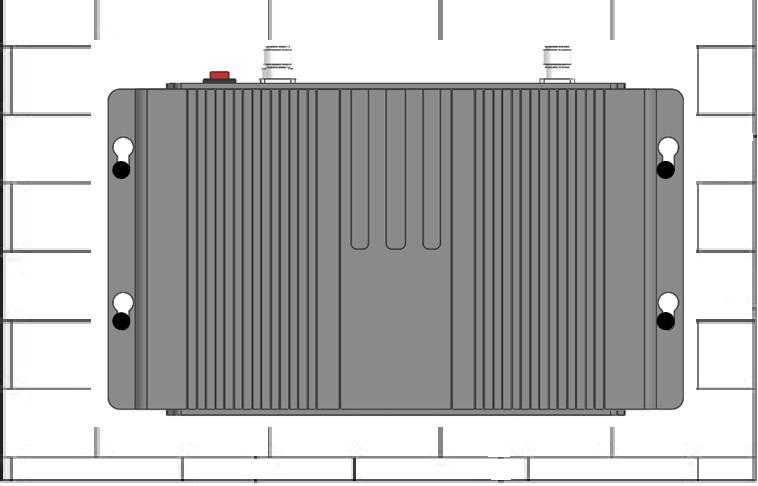
4 1. Introduction 1.1 MPG900-20T Series Repeaters The MPG900-20T Series Repeater is compact in size and light in weight. Hence, the installation of the MPG900-20T Series Repeater is easy, simply just plug and play. With the control panel in front of the repeater, the repeater status can be known during installation. 1.2 General Installation Layout Figure 1 Profile For indoor application, a typical installation layout of the Broad Band Repeater is shown in Figure 1. Use a high gain directional antenn as donor antenna. Omni and panel antennas are being used as the server antennas. The donor antenna is placed outside of the building, while the repeater is placed inside the building to extend radio coverage to the dead zones. 1.3 Advantages Fast & easy Installation The installation of a repeater is easy and simple. With its plug and play design, installation simplicity, and operational user friendliness, these features appeal greatly to many operators for the purpose of indoor coverage or for temporary coverage during network optimization. MPG900-20T has a smart function which can be activated via the front panel. This smart function can prevent UL interference and self-oscillation caused by insufficient isolation between donor and server antennas, and also setup parameters and keep optimal condition automatically; the only thing for users is just activating this function by front panel. Note. The users can t adjust by manual setting when smart function is active.
5 Auto Level Control The 25dB ALC is used to maintain steady output power even when the donor source signal fluctuates. Also when the ALC is activated, the ISOLATION LED indicator would be lighted in orange, which means the Isolation may not be enough. It also prevents UL interference and self-oscillation from insufficient isolation between donor and server antennas. Antenna isolation testing MPG900-20T series product also has an antenna isolation detection function. Equipment installation completed boot automatically after the onset detection transceiver antenna isolation, if transceiver antenna isolation can not meet the installation requirements, the device will automatically reduce the gain to guarantee the equipment in normal working, not self-excitation vibration, guarantee not to interference protection of base station, repeater itself. At the same time alarm exhibit of lanterns bright red light alarm. Device LED gain display panel will display device is reduced after the equipment current gain state, which has the advantages of convenient construction, but also to protect the base station equipment, and does not generate interference.
6 2. Installation 2.1 Isolation Isolation is an important concept for the repeater system, and it is one of the factors that affect the location of the donor antenna and the location of the server antenna. In the repeater system, the isolation must be enough, which means the donor antenna cannot be installed too close to the repeater. But what is isolation? The isolation is the propagation loss between the donor antenna and the server antenna which needs to be at least 15dB higher than the gain value of the repeater. Non-compliance to this criterion would result in poor signal quality or poor signal strength in the coverage area and the amplifier of the repeater may also be damaged. Isolation => Repeater Gain + 15 db Self-Oscillation Resistance Self-oscillation is a phenomenon that would occur when the isolation for the repeater system is not enough. In other words, insufficient isolation between donor and server antennas would result in selfoscillation. Which means part of the signal that is being amplified by the repeater radiates back towards the donor antenna and got picked up by the donor antenna and went through the repeater amplification process again. Severe oscillation issue would result in poor signal quality and at times it can even damage the repeater amplifiers. Self-oscillation will deteriorate the signals inside the coverage area and interfere towards the BTS The Isolation Value The precise estimation of the isolation value can be obtained via a physical test measurement. This test measurement is done at the actual environment where the donor antenna and the server antenna are installed for a repeater system. The test measurement procedures are 1 Connect the signal generator to the donor antenna and transmit a signal with a frequency. Choose frequency 1995MHz to do the test. In simple words, choose the idle frequency of the system to do the test) of certain power level from the signal generator. 2 Connect the spectrum analyzer to the server antenna and scan for the known frequency (The frequency used by the signal generator). Mark the received power level on the spectrum analyzer. 3 Subtract the power level received at the spectrum analyzer from the output power (OP) level of the signal generator to obtain the isolation value. Isolation (db) = Output Power from the signal generator Received Power on the spectrum analyzer Transmit a strong Output Power from the Signal generator is recommended (excess of 20dBm) for easy recognition and detection by the spectrum analyzer. 2.2 Precautions and Preparation 1 Ensure the power applied to the repeater is within its working range. A separate circuit breaker is recommended. 2 Ensure the donor antenna is installed at the location where signal from the donor BTS (Node B) is good enough. 3 Ensure there s sufficient isolation between the donor and server antenna. 4 The repeater is designed for indoor application. Ensure the location of the repeater is dry and ventilated. 5 Ensure there are adequate resources to handle the weight of the repeater. 6. Some electronic parts contain carcinogenic constituents, please handle the repeater with care, and discard the in a safe place if necessary.
7 2.3 Donor Antenna Installation The location of the donor antenna strongly influences the performance/characteristics of the RSCP and Ec/No of the intended coverage area. The donor antenna is usually installed outside of the building, pointing towards the donor BTS (NodeB) for best reception of the receiving signal. When choosing the location for the donor antenna, there are 3 criteria need to be met: 1 The RSCP of the donor signal is suggested to be in the range of -60dBm to -70dBm. 2 (Ec/No)AS_CPICH > -7dB; AS_CPICH is the Pilot Channel in Active Set (Serving Cell) 3 (Ec/No)AS_CPICH (Ec/No)MS_CPICH > 6dB The donor antenna should be installed at least 3 meters above the ground but not higher than 7th floor of any building. If the donor antenna is located at a high floor, it would be difficult to obtain a dominant BTS signal from nearby BTS. A lightning rod is necessary when the donor antenna is located at a relative high position. A 50 ohm lightning arrestor could be connected between repeater and donor antenna for better protection. Waterproofing of the antenna installation is also important, and it can be done with the following process: 1 Use the donor antenna cable to form a half loop at the point of entry into the house so that rain water would drop off instead of flowing inside along the cable, and also form a half loop before the antenna cable connects to the repeater as the waterproof measure. 2 Secure the cable entry point. Seal the donor antenna s connector and repeater s connector with a waterproof sealant. 2.4 Server antenna Installation Find the right spot to install the server antenna so the required coverage can be fully covered by the repeater is one of the most important concepts that need to be considered. However, the following three points should be considered while installing the server antenna. 1 Do not install the server antennas near metal or obstacles that may influence its coverage performance. 2 Do not install server antennas near other electronic equipment (minimum 1 meter) and not near fluorescent lamps or tubes (minimum 2 meters). 2 It is suggested to install the antennas at least 2m above the floor for the best coverage. 3 The server antenna should not be installed to close to the donor antenna to avoid issues with isolation. 2.5 Repeater Installation Installing the Repeater A lightening arrestor needs to be connected to the repeater s BTS port when the donor antenna is installed in a high position. Grounding is essential for the arrestor to work. Plug the power cable to the repeater first before plugging in the power cable to the mains socket. Use the power cable that comes with the package.
8
9 3. Commissioning This chapter outlines the process to optimize the performance of the repeater. The gain setting, isolation concept, and downlink output power. 3.1 Downlink Output Power The downlink output power of the repeater mainly depends on the input signal power and the repeater gain. The gain is the amplifying indicator for both uplink and downlink in the repeater, and it can be adjusted. Hence, the output power of the repeater can be estimated. Signal Input Power + DL Gain = DL Output Power For any given input signal power, its corresponding output is increased by the gain of the repeater. To ensure the maximum output power, the following condition should be met. DL Gain = Min [(DL Output Power Input Power), Max. DL Gain] If the input signal amplified by the gain set exceeds the rated set output limit, the ALC (Automatic Level Control) will be triggered. The ALC ensures that the maximum output power of repeater is maintained at a certain point and does not overdrive the repeaters amplification circuit. 3.2 Repeater Configuration The MPG900-20TAseries repeaters are designed with plug and play ability. The configuration for these repeaters is not necessary, simply just switch the Smart function on, and the repeater would auto adjust its gains according to the environment condition. Use the OMT software to set operator prior to installation Start-up the Repeater Note: It is suggested that only when isolation is 15dB higher than repeater s gain then the repeater can be switched on. Make sure power supply cable is connected to the repeater properly, and the voltage is within repeater s voltage working range: 110/220V ± 20% Plug the power cord into the proper socket. Once the repeater is on, it requires several seconds for initialization. When Repeater is close to the BTS, hence there is a high input power at the donor antenna. Even with the smart ability of the auto gain adjustment, it is still recommended to add an RF attenuator at repeater s BTS port to avoid interference to the BTS.


10 3.2.2 Repeater Settings After switching on the repeater, the repeater would automatically adjust both uplink and downlink gain value based on the repeater installation environment if the smart function is turned on. The repeater can also be adjusted manually via the front control panel. Figure 5 Front panel of the repeater Over all staus and Smart mode on/off, Silent Mode on/off Uplink and Downink Gain settings and alarms Buttons Function Explanations Buttons Function Explanations Smart mode key Slilent Mode key Gain attenuation key Press this key, the repeater can convert between Smart mode and normal mode. Press up to two times to switch. Make sure that the Smart LED changes. Press this key to activate or deactivate Silent mode. Silent mode on will activate the uplink sleep mode that will save energy and most of all save the load on the operators BTS Intelligent mode off, Press this key, the uplink and downlink gain will reduce. The greatest reduction is 31dB. Each press of the key is 1 db. Gain increase key When Intelligent mode turned on this key is invalid. Intelligent mode off, Press this key, uplink and downlink gain will increase. Each press of the key is 1 db. When Intelligent mode turned on this key is invalid. Store key Press Store to store all changes in settings Select Uplink/Downlink key Press Select to change from Uplink to Downlink Settings. The UL and DL LEDs will indicate selected Uplink/Downlink Battery key Enable/Disable backup battery power. Used to shut down OMT module. NOT USED ON MTG900-20T


11 LED Function Explanations Power LED DC-ON, Power LED is Green, Indicates that the power supply is normal. Run LED Green: Monitoring module is on and working Off: Monitoring module is off Alarm1 LED Green: No problems Red: Automated Gain Control is out of range Module LED Modem LED Alarm2 an Alarm3 LEDs are not used on MPG900-20T Green: OMT module has a working connection to the repeteater. Red: OMT module has problem communicating with repeater NOT USED ON MTG900-20T Smart LED Green: Smart Mode is on. Off: Smart Mode is odd Silent LED Green: Silent Mode on Off: Silent Mode off System LED Green: Indicates the active band. System1 is 900 MHz. MPG900-20T does not support other bands so System2 and System3 is not use Manual gain mode When not using Smart Mode, you can manually lower your repeaters gain by adding attenation. Every press on the - or + button will manually decrease (or increase) the total gain by 1 db. You can manually decrease gain from 70/75 down to 36/41dB. While pressing + or - the LED display will be blinking to show you your settings. Use Store key to store settings. This can be very useful if you have very strong input signal or if you need to keep internal repeater signals from leaking out from your house/appartment/office or if your operator is experiencing interfer
12 An Example of Setting (To set attenuation for the uplink) Step 1: Press SELECT till the indicator stops at uplink. Step 2: Press STORE and LED monitor starts blinking. Step 3: Press +, - to an intended gain value. Step 4: Press STORE to set the value and the LED stop blinking and showing the gain value at the moment, the process is done. 4.Maintenance 4.1 Status, Alarms possible Solutions Local alarms Alarm LED Cause Solutions Alarm1 Green Alarm1 Red Automatic Gain Control working normal Automatic Gain Control out of limit Remote alarms using OMT software Normal 1. Increase the distance between donor and server antenna 2. Decrease gain Alarm Cause Solutions DL AGC alarm 1. High input level at the BTS port of the repeater, AGC is active and more than 30dB attenuation has been applied. 3. Check antenna directions 1. Increase the separation distance of the donor and service antenna. 2. Decrease the gain by adjusting the manual attenuation accordingly to clear the alarm. PA Failure Power Module Alarm 2. An isolation condition may also have occurred. The power of PA is not stable 1. Input AC power is not stable. 2. Repeater s power supply module has been damaged 1. Check whether the input DC power is stable. If the DC is not stable, an UPS with square wave is recommended. 2. Restart this repeater. If input DC power is correct and alarm still exists, return the unit to place of purchase for repair. 1. Check whether the input AC power is stable, it should be within 110/220V ± 20%. If the AC is not stable, an UPS with square wave is recommended. 2. In the condition input AC power is correct and alarm still exists, return the unit to place of purchase for repair. PLL Unlock The PLL circuit cannot lock onto the programmed frequencies. The operating frequencies of repeater may have been accidentally shifted from the OMT software. 1. Execute the Default Setting through OMS. Refer to OMT User s Manual for more detail. 2. If the alarm cannot be solved, it means repeater has been damaged. Please return the unit to place of purchase for repair. 4.2 Troblueshooting
13 This table offers the fundamental guidelines for troubleshooting advice for the MPG900-20TA. Before sending the repeater back to the factory for service, please check the troubleshooting measures listed below first. Status Possible reason Solution No LED is lit No AC power. Check if the power cord is plugged into the repeater and the socket properly. No amplification after repeater installed. 1. Your phones is showing LTE or GSM signals. 2. Donor Signal is poor 3. Bad service antenna/cables 4. Wrong operator band? 1. If you have a LTE/4G phone it would probably lock to LTE/4G signal (even if that signal is very low) when you are not making phonecalls. This is normal. Test by locking your phone in 3G only mode or test by making a phone call and see if it switches to 3G. 2. Ensure signal strength and signal quality at the donor antenna is good enough. Check signal meter on the repeatre for input signal 3. Check cables and connector to the internal service antenna. Coverage decreased after certain period. Bad Ec/No Quality inside the coverage area Call drop frequently 1. Donor signal strength decreased. 2. The quality of feeder cable system decreased due to oxidization especially in harsh conditions, or cable damage by mice or insects. 3. Change of indoor structure or furniture. 1. Self-oscillation occurred severely. ISOLATION LED may be lighted in red. 2. Poor Ec/No Quality from donor source 1. Self-oscillation occurred. 2. Signal handover frequently. 3. Donor BTS problem 4. Check the selected operator band by the software. 1. Check the signal strength at donor antenna. Re-locate the Donor Antenna to solve problem. 2. Check the VSWR of the feeder cable system to find out the faulty point and then replace it 3. Reconsider the position of antennas and the layout of cables if such change occurs. 1. Check the isolation between donor and server antenna. 2. Adjust the donor antenna direction or relocate the donor antenna. 1. Check the isolation between donor and server antenna. Turn on the Intelligent Mode 2. Make sure the RSCP for primary BCCH > than 1st neighbor BCCH by a minimum of 6dB 3. Consult the operator s RF engineer.
F10-GSM Single System
 F10-GSM Single System 1 Table of content How it works... 3 Package contents... 4 Install your hardware... 5 Troubleshooting... 14 Specifications... 15 Product Warranty... 16 Safety Warnings... 17 2 How
F10I-EGSM Single System
 F10I-EGSM Single System 1 Table of contents How it works... 3 Package contents... 4 Troubleshooting... 14 Specifications... 15 Product Warranty... 16 Safety Warnings... 17 2 How it works Huaptec F10I-EGSM
User's Manual F10G-5S-LCD 1 / 20 BOOST CELL PHONE SIGNAL BOOSTERS MADE BY HUAPTEC
 User's Manual F10G-5S-LCD 1 / 20 BOOST CELL PHONE SIGNAL BOOSTERS MADE BY HUAPTEC Table of contents WHAT IS INCLUDED... 3 1 HOW IT WORKS... 3 2 TOOL REQUIRED... 3 3 HOW TO INSTALL YOUR NEW CELLULAR BOOSTER...
INSTALLATION AND OPERATING MANUAL
 INSTALLATION AND OPERATING MANUAL FOR RBDA-PCS-1/25W-90-A INDOOR REPEATER TABLE OF CONTENTS PARAGRAPH PAGE NO BDA OVERVIEW 3 BDA BLOCK DIAGRAM DESCRIPTION 3 FCC INFORMATION FOR USER 3 BDA BLOCK DIAGRAM
10~30dBm Series Repeater SYN-30L-S With LCD Touch Screen User Manual
 10~30dBm Series Repeater SYN-30L-S With LCD Touch Screen User Manual CONTENT PREFACE... 3 1. SAFETY WARNINGS... 3 2. INTRODUCTION... 3 3. SYSTEM CHARACTERISTICS... 5 3.1. FEATURES... 5 3.2. APPEARANCE
F10F Series Wide band booster User s Manual
 F10F Series Wide band booster User s Manual Directory F10F Series Booster User s Manual 1. Abbreviations 2 2. Safety Warnings 2 3. Application 3 4. Introduction 4 5. System Characteristics 5 5.1. Features
Technical Manual. Mobile Communication Mini Booster Model: PW-MB or PW-MB10-900
 Technical Manual Mobile Communication Mini Booster Model: PW-MB10-800 or PW-MB10-900 PW-MB10-2100 or PW-MB10-1800 Page 1 Table of Contents Introduction Name & Function How to install the system User Attentions
User Manual of W15A-WCDMA. Amplitec Corporation
 User Manual of W15A-WCDMA Amplitec Corporation CATALOGUE CHAPTER 1. SAFETY WARNING... 2 CHAPTER 2. SUMMARY... 3 CHAPTER 3. SPECIFICATIONS... 5 3.1 ELECTRICAL SPECIFICATION... 5 3.2 MECHANICAL SPECIFICATION...
Fullband Repeater User s Manual
 Fullband Repeater User s Manual PREFACE... 3 1. SAFETY WARNINGS... 3 2. INTRODUCTION... 3 3. SYSTEM CHARACTERISTICS... 5 3.1. FEATURES... 5 4.2. APPEARANCE OF THE REPEATERS... 5 4. BLOCK DIAGRAM AND WORK
3G LTE2100 4G 2600mhz Dual band signal Repeaters Max coverage 3500m2
 3G LTE2100 4G 2600mhz Dual band signal Repeaters Max coverage 3500m2 A cell phone signal booster (also known as cellular repeater or amplifier) is a device that boosts cell phone signals to and from your
INSTALLATION GUIDE Mobile Signal Repeater
 INSTALLATION GUIDE Mobile Signal Repeater NS-3G-A 2100 MHz Coverage: For Cars Preface This user s manual describes the installation and maintenance of wide band consumer boosters. Please do read user manual
Technical User Manual JDIR / 40-90
 Technical User Manual JDIR-37-87 / 40-90 Band Selective Industrial Repeater JDTECK INC. 215 Celebration Place, Suite 180-190 Kissimmee FL 34747 Abbreviations....2 Safety..2 1. Preface... 3 2. Introduction
SolidRF SOHO Tri-Band Cell Phone Signal Booster for GSM, GPRS, CDMA 3G and Verizon 4G LTE. 700 MHz(Band 13) / 850 MHz / 1900 MHz ONLY
 / 850 MHz / 1900 MHz ONLY") SolidRF SOHO Tri-Band Cell Phone Signal Booster for GSM, GPRS, CDMA 3G and Verizon 4G LTE 700 MHz(Band 13) / 850 MHz / 1900 MHz ONLY If you have any questions or concerns when installing or operating your
SolidRF SOHO Tri-Band Cell Phone Signal Booster for GSM, GPRS, CDMA 3G and Verizon 4G LTE 700 MHz(Band 13) / 850 MHz / 1900 MHz ONLY If you have any questions or concerns when installing or operating your
User Warnings MUST READ!
 Abbreviations....2 Safety..2 1. Preface... 3 2. Introduction / Features & Functions..5 3. Installation.7 3.1 Installation Procedure... 8 3.1 Installation Procedure Con t 9 Terminology AGC BTS CDMA db DL
User Manual. User Manual. Wide Band Booster (30dBm) 2012 February. Information in this manual is subject to change without notice
 2012 February. Information in this manual is subject to change without notice") User Manual Wide Band Booster (30dBm) 2012 February Information in this manual is subject to change without notice 1 Table of Contents 1 Overview... 3 2 System Diagram... 4 3 Technical Specification...
User Manual Wide Band Booster (30dBm) 2012 February Information in this manual is subject to change without notice 1 Table of Contents 1 Overview... 3 2 System Diagram... 4 3 Technical Specification...
User Warnings MUST READ!
 Abbreviations....2 Safety..2 1. Preface... 3 2. Introduction / Features & Functions..5 3. Installation.7 3.1 Installation Procedure... 8 Terminology BTS CDMA DL GSM iden MS PCS RF UL DL Donor LED Meaning
INSTALLATION GUIDE Mobile Signal Repeater
 INSTALLATION GUIDE Mobile Signal Repeater NS-GSM-A 900 MHz Coverage: For Cars Preface This user s manual describes the installation and maintenance of wide band consumer boosters. Please do read user manual
User Warnings MUST READ!
 Abbreviations....2 Safety..2 1. Preface... 3 2. Introduction / Features & Functions..5 3. Installation.7 3.1 Installation Procedure... 8 Terminology BTS CDMA DL GSM iden MS PCS RF UL DL Donor LED Meaning
CUSTOMER MANUAL. General Installation Guide. Indoor/Outdoor RF Repeater Systems MARCH 1,
 CUSTOMER MANUAL General Installation Guide Indoor/Outdoor RF Repeater Systems MARCH 1, 2018 WWW.EXCELWAVETECHNOLOGIES.COM 1-888-329-2878(Tel) 1-888-318-5528(Fax) Disclaimer This document is provided for
User Warnings MUST READ!
 Abbreviations....2 Safety..2 1. Preface... 3 2. Introduction / Features & Functions..5 3. Installation.7 3.1 Installation Procedure... 8 Terminology BTS CDMA DL GSM iden MS PCS RF UL DL Donor LED Meaning
Guide. Installation. Wilson Electronics, Inc. In-Building Wireless Amplifi er. Contents:
 Amplifier Installation Guide In-Building Wireless Amplifi er Contents: Guarantee and Warranty 1 Antenna Options and Accessories 2 Before Getting Started / How It Works 2 Installation Overview 3 Installation
Nikrans LCD-Boats-Voice, 3G & 4G
 WWW.CELL-PHONE-SIGNAL-BOOSTER.COM INSTALLATION GUIDE CELL PHONE AMPLIFIER Nikrans LCD-Boats-Voice, 3G & 4G Freq.: 850, 1900, 1700 MHz Coverage: Car/Boat PREFACE This user s manual describes the installation
EU Series Consumer Mobile Signal Booster Single Band (GSM/DCS/WCDMA/LTE800/LTE1800/LTE2600) Dual Band (ED/EW/DW/L800/L2600)
 Dual Band (ED/EW/DW/L800/L2600)") EU Series Consumer Mobile Signal Booster Single Band (GSM/DCS/WCDMA/LTE800/LTE1800/LTE2600) Dual Band (ED/EW/DW/L800/L2600) 1 Table of content Preface... 3 Safety Warnings... 3 Overview... 4 Package contents...
EU Series Consumer Mobile Signal Booster Single Band (GSM/DCS/WCDMA/LTE800/LTE1800/LTE2600) Dual Band (ED/EW/DW/L800/L2600) 1 Table of content Preface... 3 Safety Warnings... 3 Overview... 4 Package contents...
REDUTELCO TECHNOLOGY CO.,LTD.
 User Manual Wide Band Repeater REDUTELCO TECHNOLOGY CO.,LTD. 2013 January Information in this manual is subject to change without notice http:www.redutelco.com 2009 Redutelco All rights reserved 1 Table
GSM900*3G 2100mhz Dual band Signal Booster Signal Repeater for home/office use ST92A Repeater Max coverage 100sqm
 GSM900*3G 2100mhz Dual band Signal Booster Signal Repeater for home/office use ST92A Repeater Max coverage 100sqm What is the booster? Cell phone signal booster (also named repeater, amplifier) is a product
Dual Band Home Booster
 Dual Band Home Booster DBHB-20 Dual Band Home Booster 800 & 1900 MHz INSTALLATION AND OPERATION MANUAL 5700 9004 055 REV. 1.0 August 2005 Proprietary Information The information contained herein is proprietary
User Manual. CSR-DMT channel selective digital TETRA repeater
 User Manual CSR-DMT channel selective digital TETRA repeater CSR-DMT channel selective digital TETRA repeater Rev 3-NM, Issued Nov. 2017 Page 2 of 16 TABLE OF CONTENTS TABLE OF CONTENTS... 3 CONTACT INFORMATION...
Contact Tech Support at or at Safety and Warnings
 ! Safety and Warnings Turn AC power OFF at the mains before working on any electrical connections. All AC power wiring and coaxial cable wiring must conform to local or national codes. The AC line voltage
Nikrans NS-GDW-Drive
 WWW.MOBILE-SIGNAL-BOOSTERS.CO.UK INSTALLATION GUIDE CELL PHONE AMPLIFIER Nikrans NS-GDW-Drive Freq.: 900, 1800, 2100 MHz Coverage: Car/Boat PREFACE This user s manual describes the installation and maintenance
DJA3000. Cellular Communication Jammer. Installation and Operations Manual. Series DJA3000. Description: Cellular Communication Jammer
 DJA3000 Cellular Communication Jammer Installation and Operations Manual Series DJA3000 Description: Cellular Communication Jammer Models: DJA3040 and DJA3120 Series DJA3000 up to 4 Bands Thank you for
INSTALLATION GUIDE Mobile Signal Repeater
 INSTALLATION GUIDE Mobile Signal Repeater NS-300GW 900, 2100 MHz Coverage: 300 m 2 Preface This user s manual describes the installation and maintenance of wide band consumer boosters. Please do read user
User M anual. HiBoost Hi13/17 Series Consumer Mobile Signal Boosters MADE BY HUAPTEC
 User M anual HiBoost Hi13/17 Series Consumer Mobile Signal Boosters MADE BY HUAPTEC Table of Content Preface 3 Glossary of Terms 3 Safety Warnings 4 Overview 4 Package Contents 5 Features 7 Booster s Port
Contact Tech Support at or at Safety and Warnings
 ! Safety and Warnings Turn AC power OFF at the mains before working on any electrical connections. All AC power wiring and coaxial cable wiring must conform to local or national codes. The AC line voltage
BOSSGSM-G-HP27 GSM900mhz Mobile Phone signal booster
 BOSSGSM-G-HP27 GSM900mhz Mobile Phone signal booster A signal booster or cell phone repeater is a device used for boosting the cell phone network to the local area by the usage of a reception antenna.
User Warnings MUST READ!
 Abbreviations....2 Safety..2 1. Preface... 3 2. Introduction / Features & Functions..5 3. Installation.7 3.1 Installation Procedure... 8 3.1 Installation Procedure Con t 9 Terminology AGC BTS CDMA db DL
CEG-P10 ~ CEG-P20 GSM Series Band selective repeater User s Manual
 CEG-P10 ~ CEG-P20 GSM Series Band selective repeater User s Manual Contents 1. SAFETY WARNINGS...3 2. WHY REPEATER...4 2.1. REASON 1...4 2.2. REASON 2...4 3. INTRODUCTION...6 4. SYSTEM CHARACTERISTICS...7
REDUTELCO TECHNOLOGY CO.,LTD.
 Penta Band Booster (27dBm) REDUTELCO TECHNOLOGY CO.,LTD. 2018 January Information in this manual is subject to change without notice http:www.redutelco.com 2009 Redutelco All rights reserved 1 Table of
INSTALLATION GUIDE PHONE SIGNAL BOOSTER. Nikrans NS-5000GW. Freq.: 900, 2100 MHz Coverage: ft²
 WWW.MOBILE-SIGNAL-BOOSTERS.CO.UK INSTALLATION GUIDE PHONE SIGNAL BOOSTER Nikrans NS-5000GW Freq.: 900, 2100 MHz Coverage: 32300 ft² PREFACE This user s manual describes the installation and maintenance
User Manual. User Manual. Tri-Band Repeater February. -- Tri-Band Repeater (Model: RP33EDW) (900/1800/2100)
 (900/1800/2100)") Tri-Band Repeater (900/1800/2100) User Manual 2015 February Information in this manual is subject to change without notice http:www.redutelco.com 2009 Redutelco All rights reserved 1 Table of Contents
Tri-Band Repeater (900/1800/2100) User Manual 2015 February Information in this manual is subject to change without notice http:www.redutelco.com 2009 Redutelco All rights reserved 1 Table of Contents
INSTALLATION GUIDE. Mobile Signal Repeater. Nikrans NS-5000GDW. Freq.: 900, 1800, 2100 MHz Coverage: ft²
 WWW.MOBILE-SIGNAL-BOOSTERS.CO.UK INSTALLATION GUIDE Mobile Signal Repeater Nikrans NS-5000GDW Freq.: 900, 1800, 2100 MHz Coverage: 32300 ft² PREFACE This user s manual describes the installation and maintenance
INSTALLATION GUIDE Mobile Signal Repeater
 INSTALLATION GUIDE Mobile Signal Repeater LCD-150-4G 700, 1700 MHz Coverage: 150 m 2 Preface This user s manual describes the installation and maintenance of wide band consumer boosters. Please do read
INSTALLATION GUIDE Mobile Signal Repeater
 INSTALLATION GUIDE Mobile Signal Repeater LCD-300 900 MHz Coverage: 300 m 2 Preface This user s manual describes the installation and maintenance of wide band consumer boosters. Please do read user manual
Appearance of device and accessories may vary.
 Tri-Band 4G-V Adjustable Gain 700 (Band 13) / 800 / 1900 MHz In-Building Wireless Smart Technology Signal Booster (Band 13 is 700 MHz Verizon LTE) Tri-Band 4G-A Adjustable Gain 700 (Band 12/17) / 800 /
Wilson. iden 800 MHz. Adjustable Gain In-Building Wireless Smart Technology Signal Booster. Appearance of device and accessories may vary.
 iden 800 MHz Adjustable Gain In-Building Wireless Smart Technology Contents: Options & Accessories....................... 1 Quick Install Overview............................... 2 Installation Diagram.................................
Cellular Signal Booster Multi-User Tri-Band
 weboost Drive AM100-Pro Cellular Signal Booster Multi-User Tri-Band ! THE Drive AM100-Pro SIGNAL BOOSTER MAY REMAIN ON, IN VEHICLES WHOSE 12V DC POWER SOURCES DO NOT AUTOMATICALLY SHUTDOWN WHEN THE VEHICLE
Overview. Key Facts. TSP Transmitter. TRANSCOM Cellular Network Measurement
 TSP Transmitter Overview TSP Pilot Transmitter is a kind of special engineering instrument applicable to emulation and testing of indoor and outdoor signal coverage and evaluation and testing of signal
User Manual LTE 4G 850/2600. Wide Dual Band Repeater REDUTELCO TECHNOLOGY CO.,LTD January
 User Manual LTE 4G 850/2600 Wide Dual Band Repeater REDUTELCO TECHNOLOGY CO.,LTD. 2015 January Information in this manual is subject to change without notice http:www.redutelco.com 2009 Redutelco All rights
INSTALLATION GUIDE. Mobile Signal Repeater. Nikrans NS-2500GDW. Freq.: 900, 1800, 2100 MHz Coverage: ft²
 WWW.MOBILE-SIGNAL-BOOSTERS.CO.UK INSTALLATION GUIDE Mobile Signal Repeater Nikrans NS-2500GDW Freq.: 900, 1800, 2100 MHz Coverage: 21600 ft² PREFACE This user s manual describes the installation and maintenance
INSTALLATION GUIDE. Mobile Signal Repeater. Nikrans LCD-300. Freq.: 900 MHz Coverage: 3300 ft²
 WWW.MOBILE-SIGNAL-BOOSTERS.CO.UK INSTALLATION GUIDE Mobile Signal Repeater Nikrans LCD-300 Freq.: 900 MHz Coverage: 3300 ft² PREFACE This user s manual describes the installation and maintenance of wide
INSTALLATION GUIDE. Mobile Signal Repeater. Nikrans LCD500-4G-D. Freq.: 800, 1800 MHz Coverage: 5400 ft²
 WWW.MOBILE-SIGNAL-BOOSTERS.CO.UK INSTALLATION GUIDE Mobile Signal Repeater Nikrans LCD500-4G-D Freq.: 800, 1800 MHz Coverage: 5400 ft² PREFACE This user s manual describes the installation and maintenance
INSTALLATION GUIDE Mobile Signal Repeater
 INSTALLATION GUIDE Mobile Signal Repeater MA-400D 1800 MHz Coverage: 400 m 2 Preface This user s manual describes the installation and maintenance of wide band consumer boosters. Please do read user manual
INSTALLATION GUIDE Mobile Signal Repeater
 INSTALLATION GUIDE Mobile Signal Repeater MA-250GW 900, 2100 MHz Coverage: 250 m 2 Preface This user s manual describes the installation and maintenance of wide band consumer boosters. Please do read user
INSTALLATION GUIDE. Mobile Signal Repeater. Nikrans LCD-300GD. Freq.: 900, 1800 MHz Coverage: 3300 ft²
 WWW.MOBILE-SIGNAL-BOOSTERS.CO.UK INSTALLATION GUIDE Mobile Signal Repeater Nikrans LCD-300GD Freq.: 900, 1800 MHz Coverage: 3300 ft² PREFACE This user s manual describes the installation and maintenance
Nikrans LCD250-GSM+4G
 WWW.MOBILE-SIGNAL-BOOSTERS.CO.UK INSTALLATION GUIDE Mobile Signal Repeater Nikrans LCD250-GSM+4G Freq.: 900, 2600, 800 MHz Coverage: 2700 ft² PREFACE This user s manual describes the installation and maintenance
Nikrans NS-150-3G-4G-PRO
 WWW.CELL-PHONE-SIGNAL-BOOSTER.COM INSTALLATION GUIDE Mobile Signal Repeater Nikrans NS-150-3G-4G-PRO Freq.: 900, 1800, 850, 2100, 2600 MHz Coverage: 1700 ft² PREFACE This user s manual describes the installation
INSTALLATION GUIDE Mobile Signal Repeater
 INSTALLATION GUIDE Mobile Signal Repeater LCD-300GD 900, 1800 MHz Coverage: 300 m 2 Preface This user s manual describes the installation and maintenance of wide band consumer boosters. Please do read
ITEM : CELLULAR REPETER MODEL : MGR-319H
 User s Manual ITEM : CELLULAR REPETER MODEL : MGR-319H MAXUS Technologies, Inc. 2963 Sujin-D o ng, Sujung -G u, Se o ng N a m - Si, K y e o ng G i D o, K o r e a T e l + 8 2-31 -7 5 4-6633 F a x + 8 2-31
INSTALLATION GUIDE Mobile Signal Repeater
 INSTALLATION GUIDE Mobile Signal Repeater NS500-GSM+4G-PRO 900, 800, 2600 MHz Coverage: 500 m 2 Preface This user s manual describes the installation and maintenance of wide band consumer boosters. Please
800 MHz BIDIRECTIONAL AMPLIFIER Technical manual
 COMPROD COMMUNICATIONS LTD. Customer Instruction Manual Model # BDA-806870 800 MHz BIDIRECTIONAL AMPLIFIER Technical manual 2015, Comprod Communications LTD. 88 Industriel Blvd Boucherville, QC, J4B 2X2
INSTALLATION GUIDE. Mobile Signal Repeater. Nikrans LCD-130. Freq.: 900 MHz Coverage: 1400 ft²
 WWW.MOBILE-SIGNAL-BOOSTERS.CO.UK INSTALLATION GUIDE Mobile Signal Repeater Nikrans LCD-130 Freq.: 900 MHz Coverage: 1400 ft² PREFACE This user s manual describes the installation and maintenance of wide
INSTALLATION GUIDE MOBILE SIGNAL BOOSTER. Nikrans LCD-1503G. Freq.: 2100 MHz Coverage: 1700 ft²
 WWW.MOBILE-SIGNAL-BOOSTERS.CO.UK INSTALLATION GUIDE MOBILE SIGNAL BOOSTER Nikrans LCD-1503G Freq.: 2100 MHz Coverage: 1700 ft² PREFACE This user s manual describes the installation and maintenance of wide
HiBoost Home 4K Smart Link
 WWW.CELL-PHONE-SIGNAL-BOOSTER.COM INSTALLATION GUIDE REPEATER HiBoost Home 4K Smart Link Freq.: 850, 1900, 1700, 700 MHz Coverage: 3200 ft² PREFACE This user s manual describes the installation and maintenance
REDUTELCO TECHNOLOGY CO.,LTD.
 User Manual Wide Tri Band Booster (23dBm) REDUTELCO TECHNOLOGY CO.,LTD. 2013 January Information in this manual is subject to change without notice http:www.redutelco.com 2009 Redutelco All rights reserved
Nikrans NS G-4G-PRO
 WWW.CELL-PHONE-SIGNAL-BOOSTER.COM INSTALLATION GUIDE Mobile Signal Repeater Nikrans NS-1000-3G-4G-PRO Freq.: 900, 1800, 850, 2100, 2600 MHz Coverage: 10800 ft² PREFACE This user s manual describes the
What s In The Box. 1x, 2x, or 4x Indoor Antenna(s)* Coaxial Cable. Other Parts. 2x, 3x, or 5x 30 ft RS400 Cable* 1x 1 ft RS240 Cable** Panel Antenna
* Coaxial Cable. Other Parts. 2x, 3x, or 5x 30 ft RS400 Cable* 1x 1 ft RS240 Cable** Panel Antenna") Read This First CEL-FI GO X Installation Guide 26081 Merit Circle, Suite 118 Laguna Hills, CA 92653 +1 (800) 761-3041 www.repeaterstore.com contact@repeaterstore.com What s In The Box Cel-Fi GO X Amplifier
Read This First CEL-FI GO X Installation Guide 26081 Merit Circle, Suite 118 Laguna Hills, CA 92653 +1 (800) 761-3041 www.repeaterstore.com contact@repeaterstore.com What s In The Box Cel-Fi GO X Amplifier
Stealth X2 Dual Band Boosters
 Stealth X2 Dual Band Boosters BUILDINGS HOMES COTTAGES Stealth X2 Dual Band Boosters Table of Contents Features...3 Specifications...3 Package contents...4 Optional Parts...4 Antenna and Booster Installation...5
CELLULAR DISTRIBUTION SYSTEM
 Overview OCC s patented Cellular Distribution System (CDS) is a wireless enhancement product designed to resolve low cellular signal strength issues for in-building applications. Designed as a complete
A WILSON ELECTRONICS BRAND DRIVE 4G-X RV. RV Cellular Signal Booster. User Manual
 A WILSON ELECTRONICS BRAND DRIVE 4G-X RV RV Cellular Signal Booster User Manual Index Package Contents 1 STEP 1: Mount Outside Antenna 2 STEP 2: Drill Entry Hole 3 STEP 3: Connect Cable To Outside Antenna
INSTALLATION GUIDE. Mobile Signal Repeater. Nikrans NS-GW-A. Freq.: 900, 2100 MHz Coverage: Car/Boat
 WWW.MOBILE-SIGNAL-BOOSTERS.CO.UK INSTALLATION GUIDE Mobile Signal Repeater Nikrans NS-GW-A Freq.: 900, 2100 MHz Coverage: Car/Boat PREFACE This user s manual describes the installation and maintenance
CEW-P10 ~ CEW-P20 WCDMA Series Band Selective Pico Repeater User s Manual
 CEW-P10 ~ CEW-P20 WCDMA Series Band Selective Pico Repeater User s Manual Contents 1. SAFETY WARNINGS...3 2. WHY REPEATER...4 2.1. REASON 1...4 2.2. REASON 2...4 3. INTRODUCTION...5 4. SYSTEM CHARACTERISTICS...6
User Manual HiBoost Hi13-23
 User Manual HiBoost Hi13-23 Single band and dual band consumer boosters 10-27dBm power range Table of Content Table of Content... 2 Preface... 3 Safety Warnings... 3 Overview... 4 Glossary of Terms...
900 MHz Digital Wireless Indoor/Outdoor Speakers
 4015007 900 MHz Digital Wireless Indoor/Outdoor Speakers User s Manual This 900 MHz digital hybrid wireless speaker system uses the latest wireless technology that enables you to enjoy music and TV sound
INSTALLATION GUIDE CELL PHONE AMPLIFIER. Nikrans LCD-1000GDW. Freq.: 900, 1800, 2100 MHz Coverage: ft²
 WWW.MOBILE-SIGNAL-BOOSTERS.CO.UK INSTALLATION GUIDE CELL PHONE AMPLIFIER Nikrans LCD-1000GDW Freq.: 900, 1800, 2100 MHz Coverage: 10800 ft² PREFACE This user s manual describes the installation and maintenance
CUSTOMER MANUAL. ERDCHS1 Series. Indoor/Outdoor Channelized Digital Repeaters JANUARY 18,
 CUSTOMER MANUAL ERDCHS1 Series Indoor/Outdoor Channelized Digital Repeaters JANUARY 18, 2018 WWW.EXCELWAVETECHNOLOGIES.COM 1-888-329-2878(Tel) 1-888-318-5528(Fax) Contents Disclaimer... 2 QUICK START...
Appearance of device and accessories may vary.
 Mobile 4G Smart Technology Signal Booster Contents: How it Works.... 1 Before Getting Started.... 2 Quick Installation Overview.... 2 Installing the Outside Antenna.... 2 Installing the Low-Profile Antenna....
A WILSON ELECTRONICS BRAND DRIVE 4G-X OTR. Cellular Booster For Trucks. User Manual. NEED HELP? support.weboost.com
 A WILSON ELECTRONICS BRAND DRIVE 4G-X OTR Cellular Booster For Trucks User Manual NEED HELP? support.weboost.com 866.294.1660 Index Package Contents 1 STEP 1: Select Mounting Location 2 STEP 2: Assemble
Copyright Teletronics International, Inc. Patent Pending
 Copyright 2003 By Teletronics International, Inc. Patent Pending FCC NOTICES Electronic Emission Notice: This device complies with Part 15 of the FCC rules. Operation is subject to the following two conditions:
Smart Automatic Level Control For improved repeater integration in CDMA and WCDMA networks
 Smart Automatic Level Control For improved repeater integration in CDMA and WCDMA networks The most important thing will build is trust Smart Automatic Level Control (SALC) Abstract The incorporation of
INSTALLATION GUIDE. Mobile Signal Repeater. Nikrans LCD-1200GW. Freq.: 900, 2100 MHz Coverage: ft²
 WWW.MOBILE-SIGNAL-BOOSTERS.CO.UK INSTALLATION GUIDE Mobile Signal Repeater Nikrans LCD-1200GW Freq.: 900, 2100 MHz Coverage: 13000 ft² PREFACE This user s manual describes the installation and maintenance
Copyright Teletronics International, Inc. Patent Pending
 Copyright 1999 by Teletronics International, Inc. Patent Pending All Rights Reserved. No part or parts of this document may be reproduced, translated, stored in any electronic retrieval system, or transmitted,
900MHz Digital Hybrid Wireless Outdoor Speakers
 4015004 900MHz Digital Hybrid Wireless Outdoor Speakers User s Manual This 900 MHz digital hybrid wireless speaker system uses the latest wireless technology that enables you to enjoy music and TV sound
Guide. Installation. Wilson Electronics, Inc. In-Building Wireless Amplifi er. Contents:
 Amplifier Installation Guide In-Building Wireless Amplifi er Contents: Guarantee and Warranty 1 Antenna Options and Accessories 2 Before Getting Started / How It Works 3 Installation Overview 4 Installing
INSTALLATION and OPERATION INSTRUCTIONS. FOR FiberLink BI-DIRECTIONAL AMPLIFIER WITH DIVERSITY MW-FBDA-800AB-50W-DIV
 INSTALLATION and OPERATION INSTRUCTIONS FOR FiberLink BI-DIRECTIONAL AMPLIFIER WITH DIVERSITY MW-FBDA-800AB-50W-DIV Page 1 of 15 TABLE OF CONTENTS PARA No. PARAGRAPH PAGE No. 1. OVERVIEW 3 2. COMPONENT
COFDM Multifunctional Receiver Operation Instructions
 COFDM Multifunctional Receiver Operation Instructions Chapter Ⅰ (1) stand a good receiving antenna. Sucker whip antenna on the outside or the roof as possible, try to rod-shaped antenna mounted on the
Multi-Channel In-Out Thermometer with Cable Free Sensor and RF Clock
 Multi-Channel In-Out Thermometer with Cable Free Sensor and RF Clock MAIN FEATURES: MAIN UNIT GB MODEL: RMR182 USER'S MANUAL INTRODUCTION Congratulations on your purchase of the RMR182 Multi- Channel In-Out
GSM DCS WCDMA Triple Band Repeater
 CRF-GDW27-F GSM DCS WCDMA Triple Band Repeater Gain 80dB, Output 27dBm Overview: CRF-GDW27-F wireless Pico Repeater is a fast and cost effective solution widely deployed to provide coverage improvement
Technical User Manual JDIR-LCPA-DR37
 Technical User Manual JDIR-LCPA-DR37 Multi-Band Industrial Digital Repeater GUI with Remote Access JDTECK INC. 215 Celebration Place, Suite 180-190 Kissimmee FL 34747 Safety..2 1. Preface... 3 2. Introduction
Ambient Level Controller
 Ambient Level Controller Installation and Use Manual Issue 1, October 1999 1999 Bogen Communications, Inc. All rights reserved. 54-2028-01 9910 Model: LUALC PEC Code: 5335-621 COM Code: 408184273 Select
Yagi and Omni Antennas Installation Manual
 Yagi and Omni Antennas Installation Manual 25500445 Rev. A0 0218 Printed in U.S.A. Copyright 2018 Federal Signal Corporation Limited Warranty This product is subject to and covered by a limited warranty,
Nikrans LCD400-GSM+4G
 WWW.MOBILE-SIGNAL-BOOSTERS.CO.UK INSTALLATION GUIDE Mobile Signal Repeater Nikrans LCD400-GSM+4G Freq.: 900, 2600, 800 MHz Coverage: 4400 ft² PREFACE This user s manual describes the installation and maintenance
i-repeater Control and monitor all your repeaters through the cloud
 i-repeater Control and monitor all your repeaters through the cloud GSM, H+, 4G 800/900/1800/2100/2600Mhz Cloud control and monitoring Touch screen interface Diagrams SMA ports for internal antennas X4
Experiencing trouble with your zboost setup? Installation Tips. Please note the following important factors in determining zboost performance:
 Experiencing trouble with your zboost setup? Please note the following important factors in determining zboost performance: 1. Vertical Separation: At least 15 vertical feet is needed between the External
GSM Amplifier/Repeater SIGNAL GSM-1205
 Code: A6785 GSM Amplifier/Repeater SIGNAL GSM-1205 Top view Rear view 1 Bottom view The included accessories 2 View of the packaging Signal GSM-1205 A6785 repeater allows to amplify GSM signals inside
DM 800H Twin Handheld UHF System (863.0Mhz-865.0Mhz)
") DM 800H Twin Handheld UHF System (863.0Mhz-865.0Mhz) User Manual Order code: MIC78 Safety advice WARNING FOR YOUR OWN SAFETY, PLEASE READ THIS USER MANUAL CAREFULLY BEFORE YOUR INITIAL START-UP! Before
DM 800H Twin Handheld UHF System (863.0Mhz-865.0Mhz) User Manual Order code: MIC78 Safety advice WARNING FOR YOUR OWN SAFETY, PLEASE READ THIS USER MANUAL CAREFULLY BEFORE YOUR INITIAL START-UP! Before
Products GSM900 CDMA800 DCS1800 PCS1900 C/G (2W) D/P (0.5W) Dual band Band selective Accessory
 D/P (0.5W) Dual band Band selective Accessory") Signal Booster Cell Phone signal booster is used to amplify the wireless signal in small area. The function is to send signal from base station to the indoor coverage directly, and through the small base
Signal Booster Cell Phone signal booster is used to amplify the wireless signal in small area. The function is to send signal from base station to the indoor coverage directly, and through the small base
SuperHALO. 2G-3G-4G Wireless Cellular Booster Kit. CA-VAT-10-R User Guide. Introduction 1-2 Installation 3-8 Troubleshooting 9-10 Specifications
 SuperHALO 2G-3G-4G Wireless Cellular Booster Kit TM Introduction 1-2 Installation 3-8 Troubleshooting 9-10 Specifications 11 Safety Information 11 CA-VAT-10-R User Guide INTRODUCTION BEFORE USE, you MUST
CITY AND COUNTY OF DENVER POLICY DENVER FIRE DEPARTMENT. Emergency Responder Radio Enhancement Coverage System (RES)
") Reference: Denver Fire Code Sections 510 Approved: Manuel Almagure Division Chief, Fire Prevention Division Number: 510-1 Effective Date: February 1, 2018 Page 1 of 8 This Policy 510-1 provides additional
Reference: Denver Fire Code Sections 510 Approved: Manuel Almagure Division Chief, Fire Prevention Division Number: 510-1 Effective Date: February 1, 2018 Page 1 of 8 This Policy 510-1 provides additional
Dual Band Home Repeater. User s Guide
 Dual Band Home Repeater User s Guide (Model#: HRD-CP0819) Hyon Corp Co,.Ltd 504-29, JAS B/D, Younnam-Dong, Mapo-Gu, Seoul, 121-869, South Korea Tel: 82-2-325-1991 / Fax: 82-2-325-2442 www.jasteletech.com
A WILSON ELECTRONICS BRAND DRIVE 4G-X FLEET PROFESSIONAL VEHICLE CELLULAR SIGNAL BOOSTER KIT. User Manual. NEED HELP? support.weboost.com
 A WILSON ELECTRONICS BRAND DRIVE 4G-X FLEET PROFESSIONAL VEHICLE CELLULAR SIGNAL BOOSTER KIT User Manual NEED HELP? support.weboost.com 866.294.1660 Index Package Contents 1 STEP 1: Mount Outside Antenna
Always there to help you. Register your product and get support at AJB4300. Question? Contact Philips.
 Always there to help you Register your product and get support at www.philips.com/support Question? Contact Philips AJB4300 User manual Contents 1 Important 2 Safety 2 2 Your FM/DAB+ clock radio 3 Introduction