THE RADIO EXPERIMENTER'S MAGAZINE. August. slier T WAVE CRAFT. Edited by HUGO GERNSBACK. New "Loop" Set needs no Aerial or Ground. r..
|
|
|
- Shon Carson
- 5 years ago
- Views:
Transcription


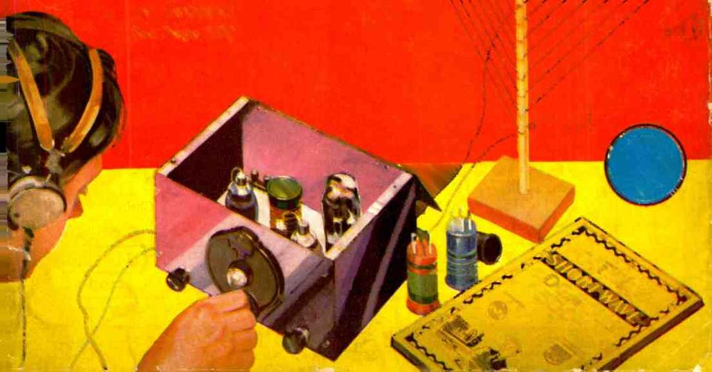


1 THE RADIO EXPERIMENTER'S MAGAZINE slier T WAVE CRAFT Edited by HUGO GERNSBACK August r.. New "Loop" Set needs no Aerial or Ground See Page 208


2 CQ de W9USA FROM 1933 WORLD'S FAIR MAKE THE HAMS' LOUNGE AT THE AMATEUR RADIO EXHIBIT YOUR HEADQUARTERS when you visit "A Century of Progress" Exposition. We are located on the second floor of the Travel & Transport Building, whose suspended dome is easily seen just south of the 31st Street entrance to the grounds. Park near this entrance, if you drive, or take the Illinois Central, 10c fare from the loop to 31st Street. Latest copies of all amateur and short -wave magazines will be available, in our lounge, as well as interesting old issues of "OST" and other publications. W9USA -W9USB frequencies used will be from the following crystals: 3505 xtal 7010 kc kc. Fone operation on the following: 3560 xtal W9DDE is Chairman of Communications, W9CYD in charge of operations, and W9CRT Traffic Manager. COME AND SEE Interesting displays of old -time amateur apparatus including some of the first receiving tubes and spark transmitters. 56 mc. transmitters and receivers in actual operation -with which interesting tests will be conducted during the Fair. Plenty of information on "5 meter" operation. The newest and best in amateur receivers and transmitting equipment, as displayed by the leading radio manufacturers. Write W9APY or W9FO for further information on this big AMATEUR exhibit. Write W9CRT or W9DDE for information on station schedules and operation. Plan Your Chicago Visit to Include the BIG "WORLD-WIDE" AMATEUR RADIO CONVENTION THREE DAYS of personal contact with ham friends, August , at the Medinah Michigan Avenue Club, 505 N. Michigan Ave., Chicago. The best time you will ever have at a convention, with interesting and valuable demonstrations and discussions by prominent short -wave men. Don't miss it! If your local club has not received full information on the Convention, write W9AAW, Convention Chairman, for details. WORLD'S FAIR RADIO AMATEUR COUNCIL 19 SO. WELLS STREET Suite 1005 CHICAGO, ILL.


3 SHORT WAVE CRAFT for AUGUST, BE A RADIO EXPERT Many Make $loo 50,0 a Week.T. E. Smith President, National Radio Institute the man who has directed the Home -Study training of more men for the Radin Industry than any at her m:m in America. fl raía Yu at Home in Zur Spare ine f0rradio -TELEVISION -TALKING MOVIES p Set Servicing Spare -time set servicing pays many N. R. I. men $200 to $1,000 a year. Full - time men make as much as $65, $75, and $100 a week. Broadcasting Stations Employ trained an e n continually for jobs paying as much as $5,000 a year. Ship Operating Radio r < on.hips act th,- world free and get good puy plue expenses. I Ieré s one enjoying shore leave. Aircraft Radio Radio., flying sa fer. Radio operators employed through Civil Service Commission earn 81,620 to $2,800 a Talking Movies An invention made possible by Radio. Employs many well - trained Radio men for jobs paying $76 to $200 a. week. Television The coming field of many great opportunities is covered by my course. IF you are dissatisfied with your present job, if you are struggling along in a rut with little or no prospect of anything better than a skinny pay envelope -clip the coupon NOW. Get my big FREE book on the opportunities in Radio. Read how quickly you can learn at home in your spare time to be a Radio Expert -what good jobs my graduates have been getting -real jobs with real futures. Many Radio Experts Make $50 to SI00 a Week In about ten years the Radio Industry has grown from $2,000,000 to hundreds of millions of dollars. Over 300,000 jobs have been created by this growth, and thousands more will be created by its continued development. Many men and young men with the right training -the kind of training I give you in the N. R. I. course -have stepped into Radio at two and three times their former salaries. Get Ready Now for Jobs Like These Broadcasting stations use engineers, operators, station managers, and pay up to $5,000 a year. Manufacturers continually employ testers, inspectors, foremen, engineers, service men, buyers, for jobs paying up to $6,000 a year. Radio Operators on ships enjoy life, see the world, with board and lodging free, and get good pay besides. Dealers and jobbers employ service men, salesmen, buyers, managers, and pay up to $100 a week. My book tells you about these and many other kinds of interesting Radio jobs. Mang Make as, me, ta a Week Zama tuggers Time Almost at Ones The day you enroll with me, I send you instructions which you should master quickly for doing 28 jobs common in most every neighborhood, for spare -time money. Throughout your course I send you informa- Special Free Offer Act now and receive in addition to my big free book, "Rich Rewards in Radio," this Service Manual on D.C.. A.C., and Battery operated sets. Only my students could have this book in the past. Now readers of this maga- zine who mail the coupon will receive it free. Overcoming hum, noises of all kinds, fading signals, broad tuning, howls and oscillations, poor distance recep- tion, distorted or muffled signals, poor Audio and Radio Frequency amplification and other vital servier information is contained in it. Get a free copy by mailing the coupon at right. Act nowt tion on servicing popular makes of sets! I give you the plans and ideas that have made $200 to $1,000 a year for N. R. I. men in their spare time. My course is famous as the course that pays for itself. Talking Movies, Wave, Money- Back? magreeent Included training in Talking Movies, Television and Home Television experiments, Short Wave Radio. Radio's use in Aviation, Servicing and Merchandising Sets, Broadcasting, Commercial and Ship Stations are included. I am so sure that N. R. I. can train you satisfactorily that I will agree in writing to refund every penny of your tuition if you are not satisfied with my Lesson and Instruction Service upon completion. ld Page Book of Inlermatset RILE Cet your ropy today. It's free to all residente of the United Stater and Canada over 15 years old. It tell; put ',here Itadlo's good jobs are, what they par, tells you about my Course, other.; tiro have taken It aro doing and making. Find out shat Radio offers you without the slightest obitgallon. Mall coupon in antelope or patte on postcard. ACT NOW! J. E. SMITH, President National Radio Institute Dept. 3HB3 Washington, D. C. J. E. SMITH, President National Radio Institute, Dept. 3HB3 Washington, D. C. Dear Mr. Smith: I want to take advantage of your Special Free Offer. Send me your two books, "Trouble Shooting in D.C., A.C., and Battery Sets" and "Rich Rewards in Radio." I understand this does not obligate me. (Please print plainly) Nane Address City - State Age =rt.r.,..,.t?.i: - 1,...?'rael := =/.._...


4 IN THIS ISSUE: PROMINENT SHORT -WAVE AUTHORS Shuart Denton Möller Gross Palmer HUGO GERNSBACK Editor simti WAVE (MII -mirror- H. WINFIELD SECOR Managing Editor Contents for August, 1933 Editorial -S -W "Loop" Reception, by Hugo Gernsback _.197 S -W Signals from Interstellar Space 198 Short -Wave Advances in the U.S. S. R., by Vladimir Alexandrovitch Pavloff, Leningrad, U. S. S. R 200 The Story of EAQ, Madrid, illustrated 202 A Band -Spread "Super -het" Receiver, by George W Shuart, W2AMN -W2CBC 204 "Argonaut" S -W Receiver, by Clifford E. Denton 206 Picking Up Europe on a "Loop "!, by George W. Shuart, W2AMN, W2CBC 208 Hints on S -W Aerials and Receiver Circuits, by Dr. W Möller 210 Doerle 3 -tube "Signal- Gripper" Electrified 212 -$ Prize Contest Awards for Best Cover Title 214 4,000 Mile Reception on Three Tubes, plus 4 -ft. Aerial, by D. M. Dunsmore 215 Supertone 4 -tube A. C. Set, by H. W. Secor 216 The "Regent- Four" Receiver, by C. W. Palmer 917 World -Wide S -W Review, by C. W. Palmer 218 What's New in Short -Wave Apparatus 2.20 Letters from S -W Fans 222 $5.00 for Best S -W Kinks, Monthly 223 SHORT WAVE STATIONS OF THE WORLD 224 SHORT WAVE LEAGUE -Publicity Aids for Your Club, by Robert Hertzberg The "EAGLE" S -W Receiver, by Jerry Gross 229 Short Wave Question Box 230 Book Review 249 Amateurs Who Made Good 249 "When to Listen in," by Robert liertzbertr 252 Certified Circuits SHORT WAVE CRAFT goes to a large expense in verifying new circuits published in this magazine. Whenever you see the seal shown here in connection with any of the sets published in this and future issues of SHORT WAVE CRAFT, this will be your guarantee that this set has been tested in our laboratories, as well as privately, in different parts of the country to make sure that the circuit and selected parts are right. Only "Constructional -Experimental" circuits are certified by us. When you see our certificate seal on any set described you need not hesitate in spending money for parts, because you are assured in advance that the set and circuit are bona fide and that this magazine stands behind it. SHORT WAVE CRAFT is the only magazine that thus certifies circuits and sets. OUR COVER "Loop" reception of short waves has been in vogue in Europe right along, but it is almost an unknown quantity in this country. The editors have been working on a short wave loop receiver for some time and we are glad to present this excellent article on a cleverly designed loop receiver by George W. Shuart, on part' 208 COPYRIGHT, BY H. GERNSBACK 228 Published by POPULAR BOOK CORPORATION HUGO GERNSBACK, President - - H. W. SECOR, Vice -President EMIL GROSSMAN Director of Advertising Chicago Adv. Office - - L. F. McCLURE, 737 No. Michigan Blvd. Publication Office N. Wesley Avenue. Mount Morris, Ill. Editorial and General Offices Park Place. New York, N. Y. London Agent: HACHETTE & CIE., King William St., Charing Cross, W.C.2 Paris Agent: HACHETTE & CIE.. Ill Rue Reaumur Australian Agents: McGILL'S AGENCY, 179 Elizabeth St., Melbourne FEATURES IN NEXT ISSUE A 5 -tube S.-W. "Portable" Superhet, by Clifford E. Denton. 7 -inch wave apparatus now ready. An ultra S. -W. converter- permits reception of 5-10 meter waves on ordinary B. C. receiver. First of a new series of "Beginner" articles, describing how to build an A -1 "Ham" Transmitter, by Leonard Victor, W2DHN. The "Pentallex" -using one of the new tubes in a "reffexed" circuit -It makes one tube do the work of two, by J. A. Worcester, Jr. SHORT -WAVE CRAFT- Monthly. Entered as second class matter May 1930, at the post office at Mount Morris, Illinois. under the act of Mnrch 3, Trademarks and copyrights by permission of H. Gernsback, 98 Park Place. N. Y. C. Text and illustrations of this are magazine copyrighted and must not be reproduced without permission. SHORT WAVE CRAFT is published on the 15th of every month. Twelve numbers per year. Subscription price is $2.50 a year in the United States and possessions. Canada and foreign countries, $3.00 a year. Single copies 25c. Address all contributions for publication to Editor. SHORT WAVE CRAFT Park Place. New York, N. Y. Publishers are not responsible for lost manuscripts. Contributions cannot be returned unless authors remit full postage. SHORT WAVE CRAFT is for sale at all principal newsstands in the United States and Canada. European agents: Brentanos. London and Paris. Printed in U. S. A. Make all subscription checks payable to Popular Book Corporation. 194


5 SHORT WAVE CRAFT for AUGUST, Foreign Programs Received by these3 Scott Owners in a Six -month Period 15,847 More Foreign Programs - from 320 Stations in 46 foreign lands-were received by more than 200 other Scott Owners to give this POSITIVE PROOF of SCOTT distance - getting ability Such performance records speak more eloquently of this receiver's merit than bales of laboratory curves and scientific reports so highly technical as to be understood only by trained radio engineers. Not that we haven't plenty such scientific engineering proof to offer -the curves of SCOTT Receiver performance, made by recognized independent testing laboratories, have never been bettered. But unless you're a baker you aren't interested in the kind of plums used in the pudding... the proof is in the eating. Likewise, unless you are a radio engineer the technical data regarding a receiver doesn't interest you... the proof is in actual performance in the hands of actual owners! That a receiver able to deliver such miraculous distance -getting on the short waves is also a star performer on the broadcast band, with sensitivity, selectivity, and tone quality of richness and fidelity unequalled, is simply an added reason for your wanting a SCOTT ALL-WAVE Deluxe. Soon there will be under way a great International DX Contest sponsored by the world's leading radio publications, that will bring world -fame to its winner. We confidently hope to see this contest, too, won by a SCOTT owner. But why should you wait for that further evidence? Rather, get a SCOTT yourself and go into the contest with the best chance of winning! F. L. 3TIT2INGER This Erle. Penna.. SCOTT owner. between January 1st and July 1st, logged and received verifications of 1:.ss programs from 41 stations in 22 foreign countries. Mr, Slitslager's remarkable DX -ing feat included the reception of 387 programs from Tontoise. Paris, France; 131 programs from Barranquilla. Colombia: 101 from I'JA, Berlin. Germany; and others from stations scattered all over the world map, including such remote and seldom heard Places as Bandoeng. Java; Leopoldville. Belgian Congo; and a host of other interesting and thrilling air treats unknown to owners of less capable radio receivers. A. G. LUOMA From his Chicago, Ill.. home this enthusiastic SCOTT dial- twirler reached out to listen to 1201 verified programs from stations in 26 foreign lands. Paris, France, was Ills favorite station, too, being tuned in 277 times. Followed in frequent reception Sa igon, Indo- China; Bogota, Colombia; Chelmsford. England: EQA, Madrid, Spain; and a roll -call of stations all the way from Sydney, Australia and Geneva, Switzerland to Kootwiik. Neuierlands and Merida, Yucatan. He began DX -ing because of actual enjoyment of programs received instead of for the thrill of long- distance reception alune. W. C. GANGLOFF In six months of distancegrabbing on his SCOTT this resident of Cincinnati. Ohio. succeeded in logging and getting verifications from 42 stations, located in 22 foreign countries, of 592 programs. His favorite station overseas was Barranquilla, Colombia. which came in 112 times. Paris. France, was a Nose second. with 102 verified programa received. Then, stringing along to build up his Impressive total came such little - beard stations as Khabarovsk, U. S. S. R. and many another ear -thriller from thousands of miles away. Mr. Ganglog insists that his performance could easily be duplicated by any Scott owner,... and these men are `Just Average" Radio Fans - Not Professionals! Their mighty feats of DX -ing, and those of the more than 200 other SCOTT owners mentioned, were accomplished under ordinary home reception conditions -probably no better than those you have to contend with. The reason for their remarkable performance was primarily the true ABILITY of their receivers, plus patience and easily acquired skill at tuning that may be learned by anyone. You, and a SCOTT, can do as well, and have as great thrills! How Will YOU Decide On An All -Wave Receiver? Every manufacturer of all -wave receivers can claim his product to be the "World's Best" -and most of them do! But are you convinced? Or do you sensibly demand FACTS and PROOFS? Better get the real "low- down!" For instance, find out how long the manufacturer has been continuously in business... ask to be referred to owners of several years' standing,.. learn how fully equipped is the laboratory in which his receiver is built.., insist upon a check -list of features for comparison with other receivers. We are willing to have you submit our every advertised claim to the most searching investigation... in fact, we URGE you to do so, and suggest that you get the data on the SCOTT ALL -WAVE Deluxe first, for it is truly the standard by which all fine radios must be judged. SEND THIS COUPON! It will bring you Cr,,;, ltte information about the SCOTT : \rl -WAVE Deluxe, including technical data, performance PROOFS, particulars as to how the SfÛTr is built, and a check list form to use in weighing the merits of any all -wave receiver. Mail it TODAY! , E. 14. SCOTT RADIO LABORATORIES, INC. I 4450 Ravenswood Ave., Dept. SWC -83, Chicago, III. II Send me at once, entirely without obligation of any kind, complete information about the ScoTT ALL -\CAVE Deluxe, and helpful pointers to use in determining the value of any all -wave receiver. Name Address City State


 curve for your particular receiver.")


6 1í)t) SHORT WAVE CRAFT for AUGUST, 1933 At Last! OFFICIAL SHORT WAVE LEAGUE LOGG AND CALL BOOK WE ARE happy to present to the thousands of short wave fans this new Log and Call Book, which enthusiastic readers of Short Wave Craft have been urging us to publish. Here is a book that you will feel proud to possess because it reflects your patience and perseverance in logging distant stations. It is a record you will be proud of in days to come. That, however, is not all. The Log and Call Book is the finest and most complete book of its kind ever published. There is nothing like it on the market now, nor was there ever a book published like it before. PARTIAL CONTENTS 1. It contains the largest listing of short wave stations in the world, a much larger list in fact than the list published in SHORT WAVE CRAFT, or any other magazine. Due to space limitations, no regular magazine can publish all the world stations. There are so many short wave stations, such as telegraph stations, experimental stations, ship stations, and others, which normally cannot be included in any monthly magazine list, but frequently you hear these calls and then you wish to know from where they originate. The OFFICIAL LOG AND CALL BOOK gives you this information, besides a lot of other information which you must have. 2. A large section of the book is set aside where the calls can be listed in a proper manner. This log section gives the dial settings, time, date, call letters, location, and other information. Thus, when you hear a station, you make a permanent record which is invaluable. 3. Another section has squared -paper pages on which you can fill in your own frequency (wavelength) curve for your particular receiver. This helps you to find stations which otherwise could never be logged by you. 4. A distance chart showing the approximate distances between the principal cities of the world. 5. A meter to kilocycle conversion chart. Many of the short -wave broadcasters announce their frequency in the latter scale when signing off and many listeners do not know the relation between them. 6. A list of international abbreviations used in radio transmission. 7. The complete Continental code used in all radio work. 8. A list of International Call Letter Assignments; the Clock Listing Guide. Around 9. In addition to this, you will find included a map of the world, with time indications and a host of other useful information which aids you in logging distant stations thousands of miles away. Mail this Coupon Toting! SHORT WAVE CRAFT Perk Plato, New York, N. Y. Gentlemen: 1 enclose herewith ^- -c far which send to me prepaid. Immediately Upon pub] Val inn a copy of your s book OFFICIAL SHORT WAVE LEAGUE LOG AND CALL 1100K. (Send money order, check, cash or new U. S. Stamps. Register letter if It coutalns stamps or currency.) Name..._..._..._..._......_.._..._..._. Addreeb..._ _ City State Published it Qunrterlye This is one of the finest books that the publishers of SHORT WAVE CRAFT have ever turned out. You will be proud to possess it. The size of this book is 9x12 inches, sanie size as SHORT WAVE CRAFT magazine. It is printed on a good grade of paper, and has a heavy durable cover. FOR SALE ON ALL PRINCIPAL NEWSSTANDS P R I C Z As only a limited quantity was printed for the first issue, it is possible that your newsdealer sold out his supply. Should you not be able to secure a copy at your newsstand, use the handy coupon. SHORT WAVE CRAFT PARK PLACE NEW YORK, N. Y. 11


7 HUGO GERNSBACK, EDITOR H. WINFIELD SECOR, MANAGING EDITOR C CCcG CD 1 LDD ShortWave "Loop" Reception An Editorial by HUGO GERNSBACK J IT is curious to note how custom and usage sometimes prevent worthwhile developments. In short waves, experimenters have become accustomed to aerial and ground when, as a matter of fact, it is now believed that there is something better. By this I refer to loop reception. The loop aerial, of course, is nothing new. It has been used since the early days of radio. In the past, however, its use lay chiefly in the broadcast and ship bands, although during a trip through Continental Europe last summer I observed much more widespread usage of the loop than in this country. Obviously, many advantageous characteristics of loop aerials have been overlooked during the past few years, particularly in the development of high gain tuned radio frequency, superheterodyne and regenerative receivers. There is no question that the loop offers great advantages. Here is an almost virgin field that awaits development by the short -wave experimenter. The advantages of the short -wave loop as compared to the broadcast loop lie particularly in its size, because the short wave loop may be only a fraction of the size employed for broadcast reception. As yet, no standard short -wave loop has been designed. The editors recently experimented not only with the customary loop, but also with spiral loops and other designs. Then, there is still another variety, the double loop, wherein one of the sections is made movable so as to produce the fullest regenerative effect, or the two loops may be stationary and regeneration controlled by means of a variable condenser. From this it will be seen that loop aerial reception should prove to be a veritable paradise for the experimenter, and it is to be sincerely hoped that loop reception will become more popular from now on. Of course, existing present -day circuits require some modification for loop reception. This refers particularly to the input circuit of the first tube. Another important point is that the receiver must be shielded thoroughly in relation to the loop. The reason is that excessive capacity between the loop and the receiver usually destroys the loop's directional effect. This directional property is very important. Most experimenters already know that a loop works best when turned in the direction from which the signals come -that is, facing the transmitter edgewise. The directional effect of the loop is valuable in eliminating interference from other radio transmitters. It often happens that a local short -wave station or one only a short distance away sends out such a broad or powerful signal that a distant station several thousand miles away on a nearby frequency cannot be brought in with the usual aerial and ground combination. The directional qualities of the loop help to relieve this condition, unless, of courser the two stations are in exactly the same direction, which is unusual. While we are considering the problem of interference, it has been noted that a small loop will cut out nw.n-made static to a considerable degree. This man -made static is always a bug -a-boo, and while the new types of transposed aerial lead -ins help a great deal, and are indeed a forward step, loop reception, in many cases, is even better. Experimenters should try center- tapped loops with balanced input tuning circuits, which hold some excellent promises. We also have the so- called shielded loop. Such loops have been widely used for ship direction finders, army field sets, directional reception and transmission, etc. By a shielded loop is meant one having the wires entirely encased in metal, with only a small section at the top left open. Such loops greatly enhance the directional effect, and also tend to eliminate interference between the loop itself and the receiving set. One of the reasons that loop reception is not more popular with experimenters is that most of them seem to think that different loops for different wavelengths are required. Of course, that is the best arrangement, but it is not absolutely necessary. It should be possible to build a loop for all wavelengths, and by using a multiple switch, the same as is now in use in the modern short -wave sets, to switch from one wave band to another merely by turning a switch knob. Of course, when trying out tapped loops, it is necessary to have shielded connections, but this problem offers no unusual obstacles. Those experimenters who already own short -wave sets can try loop reception simply by fitting the upright support of the loop to the usual coil form so as to fit into the coil socket. For experimental supports, ordinary broomsticks or dowel sticks work very well. The wire to be used may be the ordinary No. 16 or 18 flexible. The wire is held in place by means of tacks, brass brads, or diagonally cut saw slots..loop aerials are excellent, and offer many points of advantage both for receivers and transmitters, particularly those of the portable short -wave types. It eliminates the problem of the long wire and ground with their uncertain characteristics. Short wave sets with loop aerials can be logged and tuned very accurately. It is certain that during the next few years, loop reception will become very popular, and perhaps standard. SHORT-WAVE CRAFT IS PUBLISHED ON THE 15th OF EVERY MONTH This is the August, 1933, Issue - Vol. IV, No. 4. The next Issue Comes out August 15th Editorial and Advertising Offices Park Place, New York City 197


 at a frequency of about twenty million cycles per second, and Dr.")


8 198 SHORT WAVE CRAFT for AUGUST, 1933 The directional antenna used by Dr. Karl Jansky in detecting galactic radio waves is mounted on wheels and rotated by a synchronous motor, so that it makes one complete rotation every twenty minutes. ShortWave Signals from Interstellar Space MYSTERIOUS radio waves which appear to come from the direction of the center of the Milky Way have been discovered by Dr. Karl G. Jansky of the Bell Telephone Laboratories and were described by him in a paper delivered before the International Scientific Radio Union in Washington, D. C., on April 27, They are short waves (14.6 meters) at a frequency of about twenty million cycles per second, and Dr. Karl Jansky at one end of the antenna used for receiving galactic radio waves. wore discovered in the course of radio studies carried on as a regular part of telephone research. The intensity of these waves is very low, so that delicate apparatus is required for their detection. An investigation of their nature and source has been carried on for some time, and a preliminary report was published in December of last year.* Unlike most forms of radio disturbances, these newly found waves do not appear to be due to any terrestrial phenomena, but rather to come from some point far off in space- probably *Proceedings of the Institute of Radio Engineers. far beyond our solar system. By a series of investigations carried on over a considerable period, the direction from which these waves arrive has been determined. Measurements of the horizontal component of the waves were taken on several days of each month for an entire year, and by an analysis of these readings at the end of the year, their direction of arrival was disclosed. Directions such as northeast or southwest have no application, of course, except to things on the earth. Objects in space surrounding us are located by their right ascension, measured in hours to the east of the vernal equinox -the position in the sky in which the sun appears at the beginning of spring -and by their declination in degrees above or below the Equator. The coordinates determined for the The automatic recorder which made a continuous ink record on a moving paper strip, like that shown just opposite, of the galactic short -wave signals received by Dr. Jansky's special revolving antenna and ultra -sensitive S.W. receiver. newly discovered radio waves are a right ascension of 18 hours and a declination of about 20. The right ascension has been determined quite accurately but there is still some uncertainty about the declination. The position indicated by these coordinates is very near to the point where the plane in which the earth revolves around the sun, crosses the center of the milky way, and also to that point toward which the solar system is moving with respect to the other stars. Further verification of this direction is required, but the discovery, like that of cosmic rays, raises many cosmological questions of extreme interest. Took 40,000 Light -Years to Reach Earth Electrical energy in the form of radio waves, which scientists b e l i e v e come from a point so remote in space that it requires between 30,000 and 40,000 light -years f o r the waves to reach the earth, was heard by radio listeners throughout t h e United States in a recent broadcast. It was the first such experiment ever carried out. The sound, generated by the waves arriving at a supersensitive receiving set operated by Dr. Karl G. Jansky, research engineer of the Bell Telephone Laboratories' experimental station at Holmdel, N. J., sounded like steam escaping c

. from a radiator.")


. Mr. Caldwell, in introducing, Dr.")


 199 \"Now if you are accustomed to watching the stars in the evening sky, you have noticed that each night any given star or group of stars will rise 4 minutes")
 showing point from which interstellar short -wave s i g n a l s may be expected.")
9 1 SHORT WAVE CRAFT for AUGUST, 1933 American broadcast listeners were recently entertained by shortwave signals originating far out in interstellar space. The signals, which have also been recorded graphically on a paper chart, were picked up on an ultra- sensitive short -wave receiver on a wavelength of approximately 14.6 meters, or a frequency 20,550 kilocycles at Holmdel, N. J. A special antenna rotated by motors was used to pick up the signals from space which seemed to emanate from the region of the constellation of Sagittarius (the Archer). from a radiator. Wires carried the Accurate Records Pile Up Evidence sound from the New Jersey receiving "At first he thought naturally that.- station to the WJZ coast -to -coast net- this maximum of his had something to work. do with the sun's position and with the Dr. Jansky, speaking of his work earth's daily rotation. But when he carried on secretly for more than a began to keep accurate records of the year, said an immense amount of elec- shifting of position of this stronger trical power would be necessary to hiss, which is recorded by automatic transmit waves over such distances. measuring instruments, Mr. Jansky Some of the stars, however, have been noticed that each day its position was found to radiate as much as 500 sextil-. just a little bit ahead of the position at lion horsepower, he added. the same hour the day before. That is, in a week there would be a difference Signals Emanate from Region of of half an hour in the position of Sagittarius maximum hiss. In a month a differ- Dr. Jansky was introduced by O. H. ence of two hours. So apparently this Caldwell, former Federal Radio Commissioner, who explained how the re- ` search engineer, using an antenna rotated by motors, determined the point in the sky from which the waves apparently arrive through space. The rotation of the earth on its axis causes the waves to strike the earth at different angles, depending upon the time of day and the season of the year. By carefully checking the gathered data it was discovered that the waves were arriving from the region of the constèllation of Sagittarius (The Archer). Mr. Caldwell, in introducing, Dr. Jansky, said: "These radio impulses from the stars were discovered by Karl G. Jansky of the Bell Telephone Laboratories while he was studying the faint static hiss that can be heard on a sensitive radio set when its amplification is turned up so as to get the faintest possible signal. At Holmdel, N. J., where the Bell Laboratories have a 400 -acre tract in the woods, Mr. Jansky has a tremendously sensitive receiving set, with a long antenna system mounted on wheels so it can be turned in any direction. "Using this elaborate, sensitive equipment to listen to the faint static hiss that is always present in such a sensitive receiver even on the best days or nights, Mr. Jansky noticed that the hiss was always a little stronger corn- ing from one direction that from other directions, and also that this directional maximum was continually rotating around the horizon, approximately once every day. 30 strongest hiss was not following the sun's position at all, but was following something which gained on the sun about 4 minutes a day, or two hours a month, or a whole rotation of the heavens in a year. Mr. Jansky said nothing in public but continued to keep his records carefully over a whole year, and at the end of that time, the maximum hiss was back again, once more coming from exactly the same direction as it did on the same date 12 months before. ROTATING ANTENNA ARRAY ( MOTOR DRIVEN) 199 "Now if you are accustomed to watching the stars in the evening sky, you have noticed that each night any given star or group of stars will rise 4 minutes earlier than it did the night before, and that in a month such groups of stars are all appearing two hours earlier. If you will stop to think you (Continued on page 255) MILKY WAY. ú SAGITTARIUS LOOKING AT POINT OF MAXIMUM SIGNAL ACTIVITY C Y 4; SCOROIO SOUTHERN SKY Simplified map of the Southern sky for July 21 (10 I'. M.) showing point from which interstellar short -wave s i g n a l s may be expected. ISO tao 210' 120 FRONT CURTAIN lo ' REFLECTOR CURTAIN / REFLECTOR (FRONT CURTAIN) -2 WAVELENGTHS LONG -(MADE OF 3 /4 -ara55 PIPE) Q POTENTIOMETER 2,000 5W BAT l S. / OHMS 0.3 -MEG MAX. ACTIVITY AT I.F. DEY. / RIGHT ANGLES TO OF 'FRONT'CURTAIN RECEIVER '} f5 A G c =G 74,000 1MEG CID OHMS f TUNED CIRCUITS TERMINATION CIRCUITS (IN B0K MOUNTED ON ARRAY) 275 FT. CONCENTRIC PIPE TRANSMISSION UNE BURIED SIN. IN THE GROUND ' APPARATUS IN ' LISTENING HOUSE',v+ I ow the rotating antenna array is connected through tuned termination circuits, the short -wave signal currents then being led through a shielded cable buried in the ground to the recording amplifiers and the ink recorder itself. Chart above shows direction of maximum reception with respect to plane of antenna array used by Dr. Jansky. 100 MF TEAT P RECORDING I GALVANOMETER. SPACES GREATLY HOLMDEL, N.7. EXAGGERATED (BELL LABY) ULTRA SHORT WAVES PROBABLY REFRACTED WHEN /PASSING THROUGH LAYERS -C ó D. PERU. 5 A. 1did= 2 4, t S > 0 a 1111ii1 1.00PM i 2:00PM. 3.00PM 4:00PM. 430 I,-- Al TIME The mute evidence of the reception of short -wave signals from space is presented above, this chart showing just a small section of one of the long records made during Dr. Jansky's tests. C KENNELLY- HEAVISIDE LAYER. A SIGNAL BEAM OR PATH AT AN ANGLE OF ABOUT 40 TO REACH N.J. (HOLMDEL) D APPLETON LAYER.. a SPOT IN SPACE FROM WHICH WAVES SEEM TO EMANATE B AT A POINT IN PERU THE SIGNAL WOULD ARRIVE FROM PRACTICALLY STRAIGHT OVERNEAO. Angles at which ultra short -waves reach the earth from point in space.


 is the home of 166 million people engaged in the development of an entirely new social organization.")


10 200 SHORT WAVE CRAFT for AUGUST, 1933 ShortWave Advances in By VLADIMIR ALEXANDROVITCH PAVLOFF Very little has been known up to the present regarding radio and especially the short-wave developments in the U.S.S.R. The readers of SHORT WAVE CRAFT may count themselves fortunate in having the opportunity of reading about the latest advances made by the Soviet engineers, as described by their Technical Director,Vladimir Alexandrovitch Pavloff. As recently pointed out by Dr. Louis Cohen, eminent American radio scientist, on his return from the U.S.S.R., the Soviet radio authorities are contemplating building broadcasting stations with as great a power as 1,000,000 watts! THE Soviet Union, which occupies an area of 21 million square kilometers, (8,106,000 sq. miles) is the home of 166 million people engaged in the development of an entirely new social organization. The Soviet Union is especially in need of a highly developed system of radio -communication. In this direction short waves lend their helping hand to a marked extent. Prior to the revolution, Russia was an extremely backward country when it came to the development or application of radio. Following the October revolution the program of electrical communication assumed a new and extremely rapid tempo. We are already in possession of the largest total network of than in broadcasting stations in the world. The length of inter -city wire lines of corn- munication has been markedly developed during the last four years. The vast number of lines of communication that we are still in need of unfolds a colossal perspective for the future development of short waves in the U. S. S. R. Some idea of the possibilities for short -wave and general radio developments in this country may be gleaned from the fact that in 1931 the output of the radio industry in the U. S. S. R. was ten times larger than it was in An especially broad development has been attained by our electrical industry of the "low- voltage" class, which, in 1932 had an output 23 times larger The radio industry, in our form of classification, belongs in the group of "low-voltage" industries. The vast expansion of the electrical industry has, naturally, created unusually favorable conditions for the development of radio technique, especially of the short waves. The radio laboratories of the VESO (United Trust of Industries of Low - Voltage), employ more than a thousand engineers and assistants and, besides, have at their disposal the services of the Scientific Institutes of the Union. 250 KW Tubes! During the last four years our labor. stories have been eminently successful in the construction of powerful radio transmitters, having increased their scope by means of a broadcasting station with 600 kw. in the antenna. The construction of powerful stations naturally brought a demand for powerful generating (transmitting) tubes; we have begun producing tubes of 100 kw. capacity, and have also prepared the working model for a tube of 250 kw. capacity. In reception technique our laboratories have advanced far in respect to eliminating atmospheric disturbances, by applying filters which afford an elimination of such disturbances unattained by any other filter extant. We have in our Soviet factories a diversified assortment of radio transmitter*, 1 kw. short -wave radio -telegraph and telephone transmitter, complete with rectifier and control panel, as designed and built by the Soviet radio engineers.


11 SHORT WAVE CRAFT for AUGUST, 1933 the U. S. S. R. 201 Specially Written for SHORT WAVE CR9FT for short waves, designed for transcontinental communication. I think that a brief report concerning some of the construction features of our radio apparatus for short waves might provide a fair insight into the whole picture of short wave radio -technique in the Soviet Union. Under the peculiar conditions found in my country, there is evident an urgent demand for radio transmitters of the short -wave type, with a strength of the order of 1 kw. in the antenna. Therefore we construct and produce in our factories a series of transmitters of this particular strength. Frequency Control This class of transmitters is constructed to operate on a frequency between 3,340 and 18,700 kilocycles. A system of high frequency control of this transmitter is rendered possible in the following manner: the stabili- zation of the frequency depends upon a quartz crystal oscillator, with a range of 1,670-3,340 kilocycles. This crystal is placed in an oven in which the temperature is maintained with great exactitude by the aid of a special.1 General appearance of the U. S. S. R. professional type short -wave receiver, which is provided with signal recording circuits. Here is a powerful Soviet short -wave transmitter, designed to be operated for code or phone transmission and capable of radiating 15 kw. in the antenna. mercury thermostat. In three subsequent amplifier stages, the fundamental crystal f r e- quency is either amplified or "doubled," according to the final signal frequency desired in the antenna. Transmitter Frequency Changed by Switch transmitter The within the compass of the frequency range, is adjusted to four fixed waves, which makes it very handy in that it can be changed at will to operate on any one of the four predetermined wavelengths. The transfer from one fixed frequency to another occupies but two minutes; it is effected by making a change in the connections between the various apparatus in the transmitter. To aid in making the switch -over or frequency- change, the scales of the transmitter tuning condensers are furnished with fixed wave indicators; finally in each of the last two amplifier stages there are arranged four inductances which are grouped around a commutator- switch by means of which the required inductance coil is connected into the circuit. Each of the four inductances is conductively connected with its system of antenna connections. This transmitter works with constant frequency and also is applicable to phone as well as to code transmission. Voice modulation in the transmitter is effected by causing a change in the screen -grid potential of the final tubes in the transmitter. The microphone current is amplified by means of a two - stage audio frequency amplifier, which is operated with four tubes, the stages being of the push -pull type. For C.W. or code transmission these tubes are switched into a suitable system; code transmission is carried out by interrupting the voltage applied to the screen -grids of the tubes in the second and third amplifiers. Dual Code Transmission on 1 Transmitter For use when heavy code traffic occurs, a special transmitting apparatus developed in our laboratories is attached to the transmitter, by means of which the transmission of two code messages simultaneously is made possible besides utilizing in each channel the full strength of the transmitter for the highest speed. The transmitter is connected directly to a three -phase alternating current supply circuit, having a potential of 220 volts per phase. In the transmitter set -up, there are provided three different voltages to energize the screens and plates of the tubes, with separate rectifiers for the various elements and stages constituting the transmitter. For rectifying the current, gas -filled voltage regulator tubes of L5 amperes capacity are used for the first two stages and tubes of.4 ampere capacity for the third stage, these tubes being specially produced in our own factories and laboratories. The first two rectifiers are constructed to operate on a three phase arrange- ment. The first rectifier provides the 1,500 volts D.C. for the plate of the first amplifier, a suitable voltage being also supplied through a potentiometer for the plate of the tube used in the quartz -crystal oscillator, and also to supply suitable voltage for the screen electrode of the first amplifier. The second amplifier obtains its necessary plate and screen voltage through a suitable potentiometer. The third rectifier is provided with six gas -filled tubes, which are arranged in the system devised by Graetz, utilizing a three -phase transformer; it supplies current to the plates of the last two amplifiers at a tension of 4,000 volts, and also through a suitable potentiometer suitable voltage is applied to the plates of the second and third amplifiers, the modulating tubes, and the screens of all tubes but the first. A unique system is provided for heating the cathodes; the series of A.C. transformers employed to supply the heating current are evenly distributed or balanced between the three phases of the supply system, the voltage applied to the heater of each tube being regulated by a suitable rheostat. (Continued on page 240)


12 The short -wave programs from EAQ heard by S -W "fans" all over the Americas emanate from the building shown above. The daily broadcast takes place between 5:30 and 7:00 p. m. E.S.T. The wavelength used is 30.4 meters and the power, 20 kw. SHORT WAVE CRAFT for AUGUST, 1933 The Story of "EAQ ".. The technical name of EAQ's sponsors is Radio- difusion 'hero- Americana. T h e s h o r t- wave -prog r a m s broadcast by EAQ are mainly intended for the three A m e r i- cas, but are being equally well received in all parts of the world. American shortwave "fans" are daily reporting excellent reception of station EAQ, located at Madrid, Spain. Photo at left shows the antenna system of the station, together with the station transmitter building. A view of the powerful a n d well laid out transmit- ting equipment is shown below. RADIODIFUSION Ibero- Americana is an all Spanish organization, created by the initiative of a private company, Transradio Espanola, which began making short -wave wireless telephony tests on May 20th, 1931, for the whole world, amplifying them by the inclusion of music on August 8th, These tests met with great success, and such was the number of letters received from radio -enthusiasts that the management decided to create a special department to establish a regular serv- ice. This department was called RADIO - DIFUSION IBERO- AMERICANA and with its formation a great improvement was effected in the quality of the matter broadcast. Finally, on May 21, 1932, His Excellency, the President of the Spanish Republic, officially inaugurated the Pioneer Intercontinental Broadcasting Service of Radiodifusion Ibero- Americana. The programs of EAQ, the shortwave station of Radiodifusion Ibero- Americana, are mainly intended for the three Americas, but are equally well received in all parts of the world. The daily broadcast takes place between 5:30 and 7:00 p. m. E. S. T., and on Saturdays a special transmission is made for European listeners, between 1:00 and 3:00 p. m. E. S. T. The wavelength used is 30.4 meters and the power 20 kw. The programs are composed of practically all Spanish music, entertaining lectures, and an extensive news bulletin (Continued on page 233) Film Star Uses SW Transmitter Left -Here we have the well -known film star, Frederic March, who is shown using one of the new R.C.A. Victor 5 -meter transmitting sets. This is one of the prime, if not the very first, applications of 5 meter transmission to the direction of motion pictures. The set is shown in use at Hollywood. Photo at right, sent to us by Dr. L. Rohde, shows a German high- power, short -wave, transmitting tube, which as will be observed, has a water -cooling jacket provided at the bottom of the tube, the inlet water entering il one of the pipes and leaving by the second opening. The "PENTAFLEX "- 1 Tube Does the Work of 2. J. A. Worcester, Jr., originator of the "Oscillodyne" describes his latest circuit in the September issue. The first of a new series describing how to build a simple "Ham" TRANSMITTER will also appear. Water -Cooled S -W Tube


13 SHORT WAVE CRAFT for AUGUST, 1933 This S -W Set Brought News from Home THE accompanying photos at the right and below show an interesting short -wave receiver built in the laboratories of the famous Westinghouse Electric and Mfg. Co., this receiver having made quite a name for itself among the American delegates who attended the last International Radio Conference, held in Madrid, Spain, for it was on this set that the latest "news from home" was picked up on short waves. Each night during the radio conference W8XK, KDKA's powerful shortwave station transmitted a special program of market quotations, ball scores, and news items, which were picked up in Madrid on the receiver shown, by Walter C. Evans, manager of radio broadcasting for the Westinghouse Company, and "believe you me" these short -wave tidbits from home were 203 Above -the short -wave receiver in operation at Madrid -listening to the "home news." Left-close-up appearance of the receiver, showing batteries inside the case. eagerly devoured as fast as received by Mr. Evans' fellow delegates. This compact little receiver, weighed but 15 pounds with the batteries. Transmitter Goes Up! "Dials" Planes by S W Phone DIALING planes from an airport by means of short -wave phone is now an accomplished fact; when the dial is rotated and released according to the proper code, it causes the radiophone transmitter set to change the frequency of the wave radiated. Receivers can now be located quite a distance from the airport. Four different frequencies are used on the New York Chicago, and Pacific Coast pute of 'the United Airline We recently described a European S -W transmitter sent up, attached to a balloon, for signaling the upper air conditions to weather observers. This photo shows similar apparatus used by the U. S. Weather Bureau.


14 i SB I I 204 SHORT WAVE CRAFT for AUGUST, 1933 A Band -Spread How to build an I. F. amplifier, second detector and A. F. stage for the "Band- spread Converter" described in the July issue By GEORGE W. SHUART, WZAMN -W2CBC The author is here observed tuning in a "DX" station on the "hand- spread" superhet coils are used. IT is the purpose of this article to present a suitable I.F. (intermediate frequency) and audio amplifier to be used with the short -wave converter described in last month's issue of this magazine. This unit consists of two stages of high gain low -frequency R. F. amplification, second detector and an audio output tube, together with a low frequency beat OUTPUT TO I F. FILTER ON CONVERTER. f r LI RI R2 1 R4-1 / [ /1 BEAT OSCILLATOR PANEL CONTROL oscillator for C.W. reception. No shortwave super- heterodyne seems to be complete without a beat oscillator, which aids in locating short -wave broadcast stations and permits the reception of C.W. or code signals. The I.F. amplifier is built on a 7x10x1 inch base, to match that of the converter; the two units are bolted together and attached to a 7x21 inch 2ST _ I E. l' Suo.-_\7!.` {7_... oor I R1 tl Cl a RIJ i C1 C2f I F BEAT OSCILLATOR FOR C.W. - SNIELOED I I SUP. s.g Iff=I gag I II i P Rit Ri receiver here described. Special plug -in panel, which gives the neat appearance of one complete unit. The controls on the panel, from left to right, are: First knob, trimmer condenser for the first detector; next is the main tuning dial which controls the two -gang tuning condensers. Then comes the control for the screen grid voltage of the regenerative first detector; the next small knob is the volume control which varies R.F.C. 5G R7 SWITCH R12 I r' C3 RB Y a ikjiii' c OF 1EI DETECTOR. VMMINWW" NNe AMC) 56 C3 OUTPUT V V. t F LV 1 Anyone can, with a little care and a study of the above picture diagram, construct this hand- spread superheterodyne receiver. Schematic diagram is shown on the opposite page and full details of the oscillator and antenna tuning circuits were given in the first part of the article in the July issue.


15 SHORT WAVE CRAFT for AUGUST, 1933 SUPERMET Receiver 205 the cathode bias of the two I.F. stages. The large dial next in line is for controlling the low frequency beat oscillator, and the last small knob is the "on -off" switch for the beat oscillator. This makes six controls in all, which may seem as though one is returning to the days when the set that had the most dials and knobs was considered the "hottest thing in town." However, each one of these controls is really necessary, if one wants a truly "flexible" receiver. When this set was designed the new type I.F. transformers with the air - dielectric tuning condensers were not available, and the old type were used. However, the author highly recommends the use of the new style transformers, because they will hold their adjustment indefinitely, where the others require an occasional adjustment if the full gain and selectivity of the amplifier is to be obtained. A type 57 tube was used for the second detector because it allowed the oscillator output to be coupled directly to the suppressor grid. This is a very satisfactory method of coupling and the strongest C.W. signal can be heterodyned with ease. This arrange- The editors have no hesitancy in highly recommending this "band - spread" superheterodyne receiver to the short -wave fraternity. Anyone with a little skill can build some sort of superhet for short -wave reception, but what's the use if the highly congested bands are spread over such a small space on the dial that it becomes almost, if not practically impossible to select the particular stations you want to hear. With this really remarkable set built by Mr. Shuart, not only do the "amateur" and "local" S.W. commercial stations come rolling in with tremendous volume, but also the "foreigns" as well, as actual tests have demonstrated. ment also helps' to prevent the oscillator from feeding R.F. into the I.F. stages. The audio amplifier, as can be seen from the diagram, consists of a single type 56 in a resistance -coupled circuit. A pentode could be used here if one should wish greater output, but with the output of the 56 any station could be brought up to loud -speaker volume, equal to any broadcast band receiver; so unless one wishes to entertain the whole neighborhood, it is advisable to try a 56 first and then "judge for yourself." The beat frequency oscillator uses an electron- coupled circuit, which allows the plate load of the tube to be subjected to changes without noticeable effect on the stability of the oscillatory circuit. If a triode were used for the beat oscillator, with the high degree of coupling necessary to "beat" a strong station, instability would very likely be ID IF FILTER. ON CONVERTER Sa 2M? LF. 58 BEAT OSC. (PANEL CONTROL) 2 DS!. DST 57 I Ì T`Cl Tó é50v. Li. SEAT OSC. FOR Cw AUDIO 56 sf l gr z. FI TO SCREEN OF ILI (AT Schematic wiring diagram for the I.F. amplifier, which when used- with Spread Converter" tuning circuits described in the July issue, provides first -class superhet S -W receiver. the result. The coil and condenser used with this oscillator are manufactured for this service. It has the same appearance as the I.F. transformers, and contains the grid condenser and grid - leak inside the shield. In order to have a panel control for the beat oscillator a separate tuning condenser must be connected in parallel with the one al- the "Banda complete ready in use inside the shield. The method used in this set was to mount a 35 mmf. Hammarlund midget condenser inside of a small coil shield, so that when the condenser is drawn to the panel for mounting the shield can presses tightly against the panel and forms a complete shield. It will be (Continued on page 244) Top and bottom views of the hand- spread superhet receiver are reproduced above.


 on the right - hand side of the front panel and mount the rheostat (9) on the left hand side of the panel.")
16 206 SHORT WAVE CRAFT for AUGUST, 1933 The "Argonaut" short -wave receiver works on two dry cells for "A" battery and a single 45 -volt "13" battery. Well designed plug -in coils provide maximum efficiency. The set uses two type 30 tubes and "foreigns" as well as "locals" galore have been heard with it, many of them on the loud speaker. THE Argonaut is a real "beginners'" set. Due to the simplicity of the circuit used, it is practically impossible to go wrong in the assembly or wiring. Only two tubes are used and these are of the simple three -element type, made up of a single grid, a plate and a filament. Ease of tuning and absolute re- liability characterizes the completed job. This set combines the best features of hundreds of short -wave circuits worked out by the author during the past five years. The circuit utilizes a regenerative detector, employing a 30 tube, and an audio power stage, also using a 30 tube. One of the best features of this powerful little receiver is the fact that it requires only two 1% volt dry cells and a single "B" battery. While designed for headphone reception, it is possible to bring in many SPECIAL NOISELESS AERIAL,,,,JJR n(xler FI qp G :,Q 10 AERIAL ( SEC T EXT. GROUND,F d CHASSIS The "Argonaut" By CLIFFORD E. DENTON' Here is just the receiver many of our friends have been looking for -a well- designed, "DX" getting, 2- tuber -and it works on batteries. Two 2 -volt type 30 tubes are utilized, one for the regenerative detector and the other for the audio power stage. It is designed for head -phone reception, but even "foreign" stations have been heard on a loud speaker with the "Argonaut." foreign s t a tions with ample loud speaker y o 1 ume with the Argonaut. Regeneration Control is Smooth Regeneration is controlled by smooth w o r king potentiometer, assuring perfect adjustment. The average time required to build the Argonaut is about 30 minutes. All parts are available in a complete kit form which includes drilled metal panel and chassis. Hence there is no occasion to shop around for "hard - to -get" parts, nor is a drill necessary to make mounting holes. The sockets are riveted to the chassis. The instructions accompanying the Argonaut are unusually complete, so that a successful job is pre- assured. A laboratory assembled and wired receiver may also be obtained, with a list of foreign stations actually logged on it. Constructing the "Argonaut" 2 -Tuber The chassis comes drilled with mounting holes and with sockets riveted in place. The variable tuning condenser (10) is equipped with stay bolts, which can be slipped into the holes pro- O +fì) PH ORES SPEAKER. CA- ta+ B B+45 W 67.5V Schematic wiring diagram for the 2 -tube "Argonaut," battery- operated short -wave receiver here described. a vided for them in the chassis. The first step is to fasten the variable condenser in place. Before fastening the panel to the chassis, it is important that the small drive unit of the tuning dial be inserted in place, as it is impossible to put this on after the panel is bolted to the chassis. After the drive unit is fastened, mount the escutcheon plate on the panel and fasten the panel to the chassis by means of two small 6-32 round head screws. Then mount the 100,000 ohm regeneration control (8) on the right - hand side of the front panel and mount the rheostat (9) on the left hand side of the panel. Make sure that all parts are mounted securely. Slip the edge of the dial into the wedge drive of the tuning control shaft, and slide the tuning condenser into place, after one 5" length of wire has been soldered to the stator soldering lug terminal and another 5" length of hook -up wire has been soldered to the rotor lug terminal. Fasten the audio transformer (6) on top of the chassis with the secondary terminals toward the back of the chassis (away from the panel). Mount the triple binding post (1) and the twin phone jack (2) on the rear chassis wall, as indicated. Next turn the chassis upside down and mount the R.F. choke (5), using the 2" transformer fastening bolt to hold the wood dowel in place. The R.F. coil should be 1" from the underside of the chassis. Part No. (3) is next constructed and fastened in place as follows: A 1,4" piece of No. 14 bare wire is soldered to the short antenna binding post of (1). A short piece of No. 18 push -back wire is soldered to the long antenna post. About 14 turns of this wire are wound closely around the bare wire. The other end of the push -back wire is not connected to the bare wire, but is left open. This now leaves two mica condensers, a tubular condenser and a small fixed resistor to be mounted. These parts are soldered into place during the process of wiring and naturally should be placed as close as possible to the other components with which they function. How to Wire Set Start the wiring by wiring in the filament circuit. Anchor the cable to the chassis by means of a knot on the Chief Engineer, Federated Purchaser, Inc.


 by sliding the small coil of wire on the bare No. 14 wire.")


.")
 B 13 Ii i `';.N Al- LS`.j 32.")
17 SHORT WAVE CRAFT for AUGUST, 1933 Short.Wave Receiver 207 inside rear chassis wall and use one of the cable conductors to wire directly to the rheostat (9). The chassis may be used as a positive filament return lead. Note: -Do not depend on the chassis as a return circuit for the tuning circuits. Run wires to all points in the high frequency circuits. Wire grid circuits next, then plate circuits and by -pass condensers. This completes the wiring. Putting the "Argonaut" Into Operation To place the set in operation, connect the two dry cells to the "A" leads and the "B" battery to the "B" leads. Insert the phones into phone tip jacks (2). Connect the antenna either to the long or short antenna post and connect ground to ground post. The importance of using a good antenna and ground cannot be overlooked. Place the two tubes in the sockets and turn the filament rheostat up slightly. If a voltmeter is available, check the voltage to make sure that 2 volts is supplied to the filaments of the two tubes. As the dry cells are new, it will be necessary to place the contact arm of the filament rheostat on the first turn of wire; as the batteries age, it will be necessary to move the contact arm around so that less resistance is in the circuit. With one of the short wave coils inserted in the coil socket, adjust the antenna series condenser (3) by sliding the small coil of wire on the bare No. 14 wire. Each antenna will require a separate adjustment, but once made no further adjustment is required. Experi- mentation will indicate the proper value of this small condenser. Advance the regeneration control to the right until the tube goes into oscillation. If the receiver goes into oscillation too quickly it will be necessary to increase the coupling between the antenna by means of the adjustment of (3). Some types of short coils go into oscillation snore readily than others. Tests show that the average short -wave tickler coil has too many turns. It might be advisable in some cases to take off one or two turns from the tickler winding. Tuning Hints Slowly turn the tuning knob and advance the regeneration control to the right. Stop tuning the regeneration control when the set goes into oscillation. Keep turning the tuning condenser until a station is heard. If it is a phone station, the speech will be indistinct and accompanied by a whistle. Turn the regeneration control to the left until the signal clears up, and voice or music can be heard distinctly. Try to work the set always under the point of oscillation, so as not to cause annoyance in nearby short -wave receivers. Smooth regeneration control depends on having the proper filament voltage on the tubes and the proper adjustment of the small condenser (3). After testing all the bands to see that the set is operating, adjust the antenna series condenser (3) so as to eliminate "dead- spots" and also to give smooth regeneration over the entire wave band which is covered. Coils are available which will permit this receiver to tune (Continued on page 2.39) B 13 Ii i `';.N Al- LS`.j 32.'2 1I R 2 -A 01 ODNID'EL FROM UNDER- SIDE OF CHASSIS 9 \._/' h R BOTTOM VIEW OF CHASSIS. m BOTTOM VIEW OF COILS R.F. CHOKE "I 17 DIAL 15!ID E 16 K TOP VIEW OF CHASS S DOTTED LINES ARE INSIDE CONNECTIONS OF COILS. COILS PLATE ( P 4NTENWA POST BOTTOM VIEW SOCKET CONNECTIONS FOR. TUNING COND. (ROTOR) SOCKET CONNECTIONS 30 TUBES. BOTTOM VIEW GRID PLATE FIL. PLATE FIL. FIL. FI"-/ GRID The drawing above shows top and bottom views of chassis as well as details of plug -in coils and socket connections. SPECIAL NOISELESS AERIAL EEC GTOF TICKLER P TO FI G PHONES OR SPEAKER -0 AERIAL s1 O i A F TRANS,f Fl (Q) `Ó\ POTENT FIL. RHEOSTAT CHASSIS EXT. GROUND fi' A- A+ '4)1 45 B- 67.5v.VV Picturized wiring diagram which will make it an easy matter for the uninitiated to build the "Argonaut" short -wave receiver. This receiver was designed h3 Mr. Denton, who has presented many outstanding receivers in the past to readers of this magazine.


18 208 SHORT WAVE CRAFT for AUGUST, Picking Up By GEORGE W. SHUART W2AMN -WZCBC..i // A The special short -wave "Loop" antenna receiver in operation. The receiver uses but three tubes and is A.C. operated. HUNDREDS of short -wave fans have asked for methods of working a loop antenna on short -wave receivers. Loop antennas has found little favor in the short -wave field until recently, due to the inability to get them to tune to the higher frequencies and still have them large enough to have a fairly good R.F. (radio frequency) pick -up. However, in some foreign countries, short -wave experimenters are using this type of antenna with great success. How Loop Is Coupled to Detector The set described here makes use of an untuned R.F. stage to couple the loop to the detector, the loop being connected in series with the grid circuit of the R.F. stage. This is the most simple method and gives surprising results; this system of course is not directional to any extent. Note this - an outside antenna produced signals only a shade stronger than the loop! The signal -to-noise level was considerably better with the loop than that of the regular out -door antenna. The dimensions of the loop were seven turns of wire, starting at a diameter of two feet and with the turns one inch apart. When using a loop of this kind it is advisable to have the receiver completely shielded, in order that there will be no interlocking feed -back between the R.F. stage and the detector at certain frequencies. This interlocking effect was experienced with an open- mounted receiver. No trouble was experienced at all in picking up all the major foreign short -wave broadcast stations on this set. Another method tried by the writer and which gave promising results was the use of the well -known doublet antenna, "folded up" in the form of a loop antenna. This, of course, is not a "loop," but has the appearance of one. With this set -up a tuned R.F. stage was used, such as the one described by 2,000 miles on a "loop" antenna is easy enough on the broadcast band, but when it comes to hearing European short -wave stations on 20 meters -"that's a horse of a different color." It was no cinch to design a Loop type S -W set to work on the lower wavelengths, but Mr. Shuart finally mastered the problem -and he heard Europe on his first test with the set! the author in the June issue of this magazine. A' sketch of this type antenna is shown in one of the illustrations, together with the method of coupling it to the receiver. The dimensions of this antenna will depend entirely upon the frequency at which it is to be worked; also, it can be designed for a given frequency band and tuned, which should give it much greater pick -up and directional qualities. Details of Receiver Used A description of the receiver shown in the photographs will be given for the benefit of those wishing to experiment along this line. The receiver is built in a copper cabinet, with a hinged cover to allow the change of plug -in coils. The R.F. coupling tube is a type 58 which is inductively coupled to the detector tube. A type 57 is used for the detector, with a potentiometer in the screen -grid lead to control regeneration. A type 2A5 is used as a resistance- coupled audio amplifier and gives very high gain. Trouble will be experienced with the audio tube feeding back to the detector and creating a loud howl unless the plate of this tube is shunted by a.005 mf. by -pass condenser directly to the negative lead of the set. The by -pass condenser across the cathode bias resistor is a 25 mf., 25 volt electrolytic condenser. This is preferred over the usual lmf. unit usually employed here because it gives a much greater output to the tube and improves the tone quality. The coils used in this receiver are the ' ame type as those described for the Here we have a view from the rear of the "Loop" operated receiver. It is built on a copper chassis and fits into a copper cabinet. Plug -in coils are used. l


.01- MF PLUG-IN COIL iá 0.1- MEG. 2 PRI ai. 1--- 5.")


19 ' aun SHORT WAVE CRAFT for AUGUST, 1933 On A "LOOP"! r 209 CLIO PLUG -IN COIL SEC H TO H PRI. = SUP. TOK TICK. = S.G. TO P CLIP lir.01-mf. MEG MF 25 MF. U i pno t., sneer a, WAVE `'l o. CfR11flG MEG CHASSIS 1.5 -MF OHMS Y 22V - 2.5V.. FIL a+ SOCKET 500 OHMS 1-0- *0250 You will find this picturized wiring sketch very easy to follow. The receiver here described by Mr. Shuart can he used with the loop antenna described, or with a regular antenna if so desired. 3 -tube "Electrified" Doerle receiver, described elsewhere in this issue. For tuning, a 35 mmf. Hammarlund condenser is used, in conjunction with a 100 mmf. Hammarlund, giving band - spread on all frequencies from 15 to 200 meters. The R.F. choke in the grid circuit of the antenna coupling tube was left in place, in order that an out- LOOP AERIAL R.F.C. (5 MH.).01- MF PLUG-IN COIL iá 0.1- MEG. 2 PRI ai G I ITICX /oo I I ISUF H EC oi I V _ side antenna could be coupled to the set at any time to compare the gain afforded by the regular outside antenna over that of the loop on a given signal. To couple an outside antenna to the set it is only necessary to short circuit the two loop antenna binding posts, and attach the regular antenna to this point. 2 MECS Í NNW`, MF MF MF 2.5V,AC B- The "Loop" antenna is left untuned in this matters considerably. To tune a loop on 15 to small loop, which would have but M OHMS 25 MF.0005.MF B+7%. 22V B+ 160 TO 230 V particular receiver, which simplifies 30 meters would require an extremely slight "pick -up" qualities. Construction of Loop The loop antenna shown with the set in the photograph was constructed from two dowel sticks, three -quarters of an inch in diameter. One of these sticks is twenty -four inches long, and forms a horizontal support, while the other is thirty inches long; the extra six -inch piece serves to elevate the loop from the mounting base. The wire can be fastened to the frame in a number of ways, thumb -tacks could be used, or bakelite strips could be mounted on the end of each section of the frame and the wire run through holes drilled in the strips one inch apart. In the loop shown with the set, the wires were fastened in slots in the wooden frame. If one is interested in the use of a loop antenna for the reduction of background noise or man -made static, a suggestion would be to mount the loop at some remote point, that is out of the field of the noise producing machinery and power lines, and couple the loop to the set by means of a feeder line, using either transposed feeders or plain twisted lamp cord. The frame used for the loop antenna of the old Radiola models 25 and 28 battery superheterodyne r e c e i v e r s would make an ideal frame for a loop to be used in this fashion. As shown in Figure "C," the loop wound on a frame of this type will take the form of two coils wound in the same direction and placed alongside of each other. The two outer connections are, in this case, left free or unused, as in the case of the regular doublet antenna. The (Continued on page 231)


20 210 SHORT WAVE CRAFT for AUGUST, 1933 Tuned vs. Untuned Aeríals^- Hints On SW Aerial -A- = FI G.1 - -B- RESIS- TANCE NET-WORK = FIG.2 R1 R2 ) i Ca. 1 - R3... r, = FIG.4 \ Cl A FIG.3 D ) CB FIG.S Fig. 1 shows the older type hook -up of antenna circuit; 2, aperiodic antenna arrangement; 3, coupling the antenna to the "grid" circuit through a small condenser; 4, use of a "resistance- network" to couple antenna to tube; 5, use of a "band- spread" condenser CB. PART I IN the early years of radio one often read in articles written by amateurs descriptions of their home -made receivers in which not only the grid circuit of the first tube was tuned, but the antenna circuit also. Then hook -ups were used of the sort shown in Fig. 1. In sketch A capacity and inductance are connected in series. It was supposed to be especially effective for the reception of wave lengths between 200 and 600 meters, while for work on the long wave band above 1000 meters, the parallel connection of tuning capacity and inductance was regarded as superior (sketch B). To -day this view has been abandoned; it is only partially correct, for the quality of reception is also essentially influenced by the form and kind of antenna used. In antennas with high radiation resistance, tuning the antenna circuit is to no purpose, since the desired gain in volume and increase in selectivity does not occur to the desired high degree. This is also reflected in the experiences of the amateurs themselves. When the number of transmitting stations increased and the individual transmitters were built for greater power, one gave up the specially tuned antenna and contented oneself with connecting a few turns of wire in the antenna circuit by means of which the antenna circuit was then inductively connected with the grid circuit of the first tube. Aperiodic Antennas Such untuned antenna circuits are termed in radio technology semi - aperiodic antennas. In the case of loose coupling with the input circuit of the receiver they provide good selectivity and at the same time perfectly sufficient volume. If a receiver is to be constructed for short waves (meaning wavelengths between 10 and 100 meters) it is to be remembered in the case of the considerably higher frequency of these waves that the radiation resistance of the antenna increases to an extremely high degree. In the case of these waves it would therefore be senseless to have special tuning provided in the antenna circuit. For short -wave reception then only the semi- aperiodic antenna comes into consideration. It can be coupled according to several methods with the following tube circuit. If there is used for the short wave set an antenna like that shown in Fig. 2, then for short -wave reception one can use any antenna of the type employed for regular broadcast reception. Therefore, as is to be once more stressed here, there is no need of a special antenna for short -wave reception. The short -wave set can be connected to the same antenna used at other times for the broadcast receiver. One must only see to it that the location of the antenna is favorable. If we allow near the antenna wires, metal By DR. W. MÖLLER parts like gas pipes, electric wires, rain conductors and the like, these are always a source of loss for even ordinary broadcast waves, for the antenna current flows in a definite part directly over these neighboring parts to the ground and doesn't reach the set at all. With the considerably higher frequency alternating currents of the short -wave band, these losses are far greater than with the broadcast wavelengths. Whoever wishes to occupy himself with the interesting experiments of short -wave reception is first advised to examine the location of the antenna wires and see to it that any proximity to other metal parts is carefully avoided. Distances over 2 ft., are not considered harmful. The antenna is usually discussed first and then the ground connection is dismissed in a few words. This gives the reader the impression that careful arrangement of the ground wire matters but little. This is not so. Whoever works with short -waves will soon notice the great importance of the correct ar- rangement of the ground wire. It too is to be laid at a considerable distance from foreign masses of metal and for it, as for the antenna wire, a wire of not too small cross- section is to be used. One point in the ground conductor is especially to be considered, i. e., the place where the wire coming from the receiver is connected to the conductor leading directly into the ground. If one used as a ground the gas pipe or water pipe, the clamp by which the wire from the set is joined to this ground is only to be made up of parts carefully scraped clean and is to be attached securely and firmly, so that the resistance to the ground is as small as possible. If, in the case of. an imperfect ground wire system, it has too great a resistance, this error is at once evident in the reception results. In spite of careful metallic shielding of the set, it is then not possible to eliminate completely the hand -(body) capacity. As already explained, any properly, laid antenna suitable for receiving broadcast waves is also serviceable for short waves, and now this statement must be supplemented by another -that an outside antenna is not absolutely necessary. With a good room antenna of some 12 meters (38.4 ft.) in length, absolutely perfect reception of shortwaves can be attained in most locations. With the semi -aperiodic, inductively - coupled antenna, about two or three turns are to be used in the antenna coil. One can easily make antenna coils with but few turns; they are also obtainable commerically. Figure 3 shows another kind of antenna circuit hook -up for short-wave receivers. Through a small condenser (a small variable condenser of some 20 mmf.) the antenna is directly connected with the grid side of the coil lying in the grid circuit of the first tube. In operation this type of antenna hook -up r


21 r SHORT WAVE CRAFT for AUGUST, 1933 Regeneration Control Systems and Receiver Circuits shows some peculiarities, which must be recognized and exactly heeded. First, every variation or change of this coupling capacity also changes the tuning of the set. Second, over the antenna condenser, when it is set to greater capacity values, a greater amount of energy flows from the receiver into the antenna and it appears that in spite of a rigidly applied feed -back the set cannot be brought into oscillation. That is a very important point since in shortwave reception one has to operate with strong regeneration and just below the critical point at which oscillation sets in. From these considerations, the capacity of the small antenna condenser must not be of too great a value. On the other hand in the case of small capacity, only a small fraction of the received signal energy flows out of the antenna into the first grid circuit. Therefore in reception experiments with this type of antenna coupling, one must see to it that one adjusts for the most favorable capacity value in the antenna condenser; that on the one hand the oscillating ability of the regenerative detector is not curtailed and also on the other hand, its capacity is to be chosen so large that a maximum of volume results. A third type of antenna coupling is that employing a resistance network, as shown in the hook -up, Fig. 4. In the path from the antenna wire to the ground, lie the resistances Rl and R3. From them the conductor to the grid circuit coil branches off and in this branch lies resistance R2 and the coupling condenser Ca, which again is represented by a midget condenser of 20 mmf. maximum capacity. On account of the form of the resistance arrangement, this method is also called the "T-pad" method. The most practical value for the three resistances is 300 ohms each. Resistance R3 can also be chosen somewhat higher, as much as 500 ohms. Naturally they do not have a notable load; therefore those made to stand one -half watt are sufficient. In the T -pad method the resistances lying in the antenna cause a considerable damping of the antenna signal currents. This gives the advantage that likewise the natural oscillations of the antenna circuit are strongly depressed; therefore the reception is perfectly in- dependent of the form and length of the antenna used. Where there are advantages, there are usually also disadvantages. The disadvantage of the T -pad method lies in the fact that this kind of antenna coupling also takes a great deal of energy from the receiver. Therefore setting the small condenser Ca to the most favorable capacity value is here also very important. In making a short -wave receiver with coupling condenser it is advisable not to mount the latter on the front panel, since it is always very sensitive to hand capacity. Therefore it is best mounted inside the set some 4 inches from the front panel and operated by a small bakelite rod joining it to the dial. PART II Important Points in the Construction of a Short -Wave Receiver If we first solve the R.F. or high f requency amplification problem, the antenna circuit is directly followed by the grid circuit of the detector. In it, parallel to the coil we have a variable condenser used for tuning (Cl). It is best to use only specially insulated short -wave condensers. In general these have greater distances between the plates than ordinary broadcast conden- sers. The maximum capacity of the tuning condenser is to be about 100 mmf. (.0001 mf.) Instead of making the adjustment to the wave to be received only by means of a variable condenser, one may also arrange things as in Fig. 5. Here there lies parallel to the main condenser Cl another smaller one of some 20 mmf. maximum capacity. With Cl one roughly adjusts the frequency range in which the station is to be expected and then makes a closer tuning of the waveband with the small parallel condenser CB. In this way the tuning of the receiver is rendered much easier. In radio amateur circles the small parallel condenser is called the "band-spread" condenser. In connecting this tuning circuit with the elements of the detector tube, there are again some special points worth noting which are by no means so critical in the construction of (Continued on page 234) DR. MO- LLER, one of Europe's foremost authorities on shortwaves, here presents some interesting food for thought for every short-wave student. Dr. Mö1ler discusses the various forms of antenna -circuit tuning methods and the question of TUNED versus UNTUNED antennas, including a new antenna coupling system employing a RESISTANCE -NETWORK. In the second part of the article the author considers many important points in the layout of the short-wave receiver circuit, including the best method of RE- GENERATION CONTROL, the reason for using radio frequency chokes, and numerous other valuable points of interest to every short -wave fan, who is striving constantly to improve the efficiency and general control features of his receiver. _... P ( POT. A BOUT 600 OHMS) ----", = FIG.6 P Mgr P. +H -1-1,-B 'r. r d H- (POT. ABOUT OHMS), 400 TO 600 FIG.7 H+_.:; +H FIG. B S-...` -H 002- MF. - e 11 LR CR R.F.C. ph. ':' _ tl9 FIG.9 +H (F) (ANODE =PLATE) lh -ANODE (B) Czt WL y 211 +ANODE (B) Fig. 6- hook -up of grid -leak in detector circuit; 7- another hook -up for the grid - hak, 8 -use of chokes in the detector heater circuit; 9- regulation of "feedback" in S -W circuit.


 used in the output stage.")


22 212 SHORT WAVE CRAFT for AUGUST, 1933 Thousands of short-wave fans will realize the fulfillment of their dreams, when they first try this extremely "smooth- working," A.C. operated, 3 -tube short-wave receiver. The DOERLE 3 -Tube "Signal-Gripper" Electrified IN view of the wonderful results obtained from the two-tube DOERLE receiver, using the new type tubes, described last month by Mr. G. Shuart, the author decided to electrify the three -tube model, and present it to the readers of this magazine. The set described in this article is truly a wonderful short -wave receiver. Foreign short -wave stations can be brought in loud enough to operate a speaker even with only a triode (3- element tube) used in the output stage. If a pentode were used greater volume would be obtained, but then headphones would be out of the picture, and the author just can't seem to break away from phones, which are really the best for "DX" short -wave reception. How to Change Battery Model For those who already have the three -tube set, the operation of changing to the new type tubes is as follows. Remove all wiring, all sockets except t h e four -prong one on the left side of the chassis (front view) which is used for the R.F. coil. Remove the 20 ohm rheostat and replace it with a 20,000 ohm unit, which will be used for volume control. The additional parts that will be needed to convert this set are: 1 -set of six -prong, three -winding coils, Radio Trading Co mf. fixed condensers, Flechtheim mf. fixed condensers, Flechtheim mf. bypass condenser, Flechtheim ohm fixed resist- By John H. K. Brown $20.00 May Prize- Winner The Doerle "Signal- Gripper," the battery model of which was illustrated and described in detail in the November issue, is one of the most popular of all the short -wave receivers that has ever been described in Short Wave Craft. It gives the editors great pleasure to present herewith the constructional details of the A. C. electrified "Signal - Gripper," in response to the many inquiries received from our readers. or, Lynch 1-100,000 ohm resistor, Lynch Rear view of the electrified A.C. Doerle "Signal- Gripper." 1-100,000 ohm resistor, Lynch 1-250,000 ohm resistor, Lynch 1-1 Meg. resistor, Lynch 1-2,000 ohm resistor, Lynch 1-2,000 ohm variable resistor 3-Six prong sockets, Eby (Na -ald; Nat'l; Hammarlund) 1 -Five prong socket, Eby (Na -ald; Nat'l; Hammarlund) 2- Screen grid tube shields, National (Hammarlund) The old system of coupling between the R.F. stage and the detector, which is tuned impedance, is done away with and inductive coupling is used. The coils for this arrangement were obtained from the Radio Trading Co., and have three windings, one for the grid, one for the tickler, and a winding inter -woven with the grid coil for the plate circuit of the R.F. tube. Four of these coils will be needed and it is cheaper to buy them than to wind them by hand, because this is quite a diffi- cult task. Four of the old coils formerly used with this receiver are used in the R.F. stage. Instead of coupling the antenna directly to the grid of the R.F. tube, as is done in the old receiver, the antenna winding on the R.F. coil that was unused is now employed to couple the antenna to the set. Mount all the parts, following the same layout as in the old receiver, except that the audio transformer is not used Resistance - coupling is used instead because of the high plate impedance of the detecto: tube. Solder all connections with a hot and well - tinned iron, using only (Cont. on page 239)


 332 PRI.")
 O 0 40 -a0 METERS YELLOW SEC. ll T. 5-1 r SEC. 23 T.")


.")
 CRASS 5 rr4n `YEIIAOVRFi : é OAR.")
23 SHORT WAVE CRAFT for AUGUST, AN r -- ÌP -GI SEC. 1O óìi \F 5-.0 L. J 1j "11-1-1R GND I II 6 TURNS FER 2 - INCH 4 PIN BASE 3/32 6 PIN J BASE MF. _ / OHMS METERS BLUE METERS BLUE OHMS 4414.T. NE C. OR ENAM. WIRE PRI. 4T. Nt.31 w Esc. OR.!NAM. WIRE. (CLOSE WOUND) SER. ST. NE C. WIRE TICKLER Ì~ I P!SUP. ---1,r7s MEG I50V N I (2MEG. PRI. 4 T. N2.32 S_S.C. WIRE WIRE T _E. L. \TICK. ST. /ET NICK. 7T. /T NR.32 S.SC. 3' fim(ii1l NE C. 3- WIRE 12 TURNS PER. INCH IG W REO METERS RED W METERS WIRE JD FIL. ' V. YELLOW R.F. C..01 -MF /4T. r I 223/47. NE.22 I NE 22 D:W'ORENAM. 16 TURNS / D.SWIR ENAM. 40 TURNS PER f PER INCH INCH DS.C. OR EN AM. WIRE (CLOSE WOUND) 332 PRI. 77. NE. 31 D.S.C. OR ENAM. WIRE (CLOSE WOUND) O a0 METERS YELLOW SEC. ll T. 5-1 r SEC. 23 T. NR. 26 S.S.C. i4 I- ( (NE S 6 I. win WI. 1 WIRE PRI. 8T. APRI. IS T. f NE. 323.S.C. -' NE 32 S.S:á: METERS WIRE NICK. 8 T. NE. 30 S.S.C. WIRE.5. W. 2,000 OHMS 1- ' GREEN METERS YELLOW METERS PHONES 1 513/4 T. NO22 D.S.C.OR ENAM. WIRE PRI. IST. NR.31 D.S.C. OR ENAM. WIRE (CLOSE WOUND) J SEC. SOT. 1 N11.30 S.E.C. z WIRE PRI. 31T. NE C. WIRE 2TICK. 16 T. NE 30 S.S.C. WIRE ANT. ff PRI.= PTO F1 SEC.., GTOF l r SEC.,. N TOM PR I. SUP. TO TICKLER= SG TO P MF á CLIP.01-MF MF MF (RECEN. CONTROL) MF ROTOR-' I STATOR ( R.F. TUNING COND.) DET. TUNING CONO ) CRASS 5 rr4n `YEIIAOVRFi : é OAR TO 250V FIL e V. Schematic wiring diagram for the electrified Doerle "Signal- Gripper" is given in the top drawing, together with coil winding data. Picturized wiring diagram appears in lower half of the drawing.


24 214 SHORT WAVE CRAFT for AUGUST, 1933 $ Prize Contest Awards To Those Who Submitted Best Titles For Our May Cover 0-rong- zt- - '\'_-.--- T IN our May issue, we announced our Special Cover Contest. For those who missed this issue, the cover is reproduced herewith. The scene obviously shows an irate mother, who, at 2 o'clock in the morning, breaks into the room where both the father and son are busily engaged putting together their latest two -tube "World Circler." What the mother really said to the frightened pair we have no means of knowing. We, however, asked our readers to supply a suitable title to the picture, and the following were some of the conditions of that Contest. A suitable title is wanted for the front cover of this month's issue. The title should be self -explanatory and should have in it some reference to radio, short waves, or both. It should be humorous, if possible. You may submit as many titles as you wish. There is no limit. The contest officially closed in New York on May 31st -and boy, what a contest this was! 1st PRIZE -One "Royal Star" 2 -Tube Short-Wave Receiver, donated by HARRISON RADIO CO., New York City. Value $ To Fred W. Beehler, 378 E. Mansfield, Pontiac, Mich., for the title, "A Dynamic Speaker Not Yet Baffled." 2nd PRIZE -One "Powertone" 2 -Tube Battery Operated Short Wave Re- ceiver, donated by TRY -MO RADIO CO., INC., New York City. Value $ To A. Phillips, Ste. 20 Haslemere Apt. 8, Winnipeg, Canada, for the title "A Local Comes Roaring In." 3rd PRIZE -One "Midwest" Model C -4 Short -Wave Converter, donated by MIDWEST RADIO CORP., Cincinnati, Ohio. Value $ To Lewis Above-the May cover of Short Wave Craft, for the best title to which the editors o f - fered in prizes. I. e f t -Resuits: -and How! Of all the contests we have ever ran in SHORT WAVE CRAFT, this one certainly proved the contest of contests! A photograph reproduced in this magazine gives an idea of the 15,600 odd separate entries that were received. All of the entries had to be on cards 51x31 / ", the size of a postal card. This was done, of course, for uniformity, and to allow the hard -pressed judges to look through the thousands of entries that came pouring in from day to day. To be sure, there were a lot of repeaters; some of the repeaters sent in as many as 200 answers, but many contented themselves with only one or two. Most of the entries were on standard postal cards, which came in from all over the world. Others were written on pieces of paper or cardboard of the correct size. Naturally, in a contest of this kind, there was duplication galore. Every imaginable and unimaginable title that could be thought of appeared, and there was a great deal of ingenuity displayed in many of them. Here Are the "Prize Winners" G. Knepper, 457 W. Fremont St., Fostoria, Ohio, for the title, "Better 'In -Su-Late' than 'Out-So- Late,' Maw." 4th PRIZE -One 2 -Tube "Doerle" Receiver, completely wired, donated by RADIO TRADING CO., New York City. Value $8.90. To D. Harrow, 103 Malvern St., Melrose, Mass., for the title, "A Good Choke Might Help." 5th, 6th, 7th, 8th, 9th, 10th PRIZES - A 1 -Tube Short -Wave Receiver, donated by Charles Hoodwin Co., Chicago, Ill. To D. McDoren, 400 Stan - yan St., San Francisco, Calif., for the title "A Short Circuit to Bed "; Louis K. Eriksen, 1323 Intervale Ave., Bronx, N. Y., for "Their First And, as is usually the case in contests of this kind, thousands of contestants thought along the same lines. For instance, the title of QRM and all the rest of the "Qs" in all their variations stood first. Static, with hundreds of variations probably was second. Local interference, with hundreds of applications ran third; then came interference. Hundreds of contestants thought of the mother in terms of a loudspeaker, and there were thousands of variations in this thought too. Of course, the words short wares, in connection with all the others, were found in profusion. The same is the case of high frequency, and the word broadcasting in one way or another. Many had mother as an announcer, and the announcing was not very flattering to her! Then, there were hundreds of QSA. There was a good deal of cross -talk in different variations, and the term "DX," of course, came in for a lot of mention too. From all of this, you will appreciate the fact that the judges did not have exactly an easy job to run through the 15,000 odd entries, in order to determine which were the good ones and the poor ones. The judges wanted some semblance of originality, and it is to be hoped that they suseeeded in this. All in all, it is believed that the con- test was a highly successful one, for all concerned. According to the terms of the contest, the prizes have already been dispatched to the winners by the time this issue appears in print. A list of the prize winners follows: Dynamic Speaker "; E. W. Collins, 1103 Union St., Jonesboro, Ark., for "Short Waves Cause Long Raves "; Irvin Feinberg, th St., College Point, N. Y., for "Wire -less and Sleep More "; Al Dubin, 5 Ridge St., New Haven, Conn., for "Making Short Work of Short Waves "; G. P. Huntley, Jr., 400 E. 52nd St., New York City, N. Y., for "Q.R.M., Quit - Raving- Mom." 11th, 12th, 13th PRIZES -One transmitting type T -10 S Tube, donated by TRIAD MFG. CO., INC., Pawtucket, R. I., to W. L. Dunbar, 5519 Home - side Ave., Los Angeles, Calif., for "The Last Word in Radio" E. R. (Continued on page 237)


 RFC")


25 { SHORT WAVE CRAFT for AUGUST, ,000 Mile Reception On 3 TUBES +4 Ft. Aerial - And On a Loud. Speaker At That By D. M. DUNSMORE Mr. Dunsmore, who lives in San Pedro Macoris, Dominican Republic, reports marvelous reception under trying static conditions, with this simple 3 -tube receiver. HEREWITH are photos and schematic diagram of a receiver built largely from ideas given in SHORT WAVE CRAFT. I have been experimenting with short waves and building sets since Short waves are our salvation in the Tropics, as the terrific static storms are diminished at 50 meters, and scarcely heard at 35 meters and less. Excepting January, February and March, static makes long -wave reception almost impossible in these latitudes. I had always considered from the results obtained from regenerative sets built by myself, some with tuned, and others with aperiodic R.F. circuits, that no benefit was derived to merit the '97 (B5MM) RFC. 58 added complication of tuned R.F. In fact one of the finest battery sets j have ever handled is the old RCA Model AR -1145, with an untuned antenna circuit. When the new pentodes came out, I became much interested, and Mr. Martin's idea of a good three tube receiver, in your September issue, struck my fancy. I then ordered material from the States for building this set, with the modification of a self -contained power supply, and an untuned R.F. stage. Ran into two snags with Mr. Martin's circuit. One, the lack of a bias for the detector grid, was easily remedied by installing a grid condenser and leak. ' R.FC.I2 Va T010 MN. LI AU010 TRANS. CO.0001-MF R OHMS L2 30 H. CHOKE CS B MF. R3 0.1-MEG. Cl.02-MF CG 20 MF. RO 0.5-MEG. F C2.05-MF. R 6000HMS R5 SMEG. C3.006-MF. Pl 5,000 OHMS C 0.1- MF. SPEAKER RFC L.000LM, 57 C2 47 COUPLED Cl r e R.F C.1 ti R3 1 q CS t 12 J4890 Diagram of Mr. Dunsmore 's Receiver. CS 215 One of the gentler sex operating the 3 -tube receiver here described, and which has distinguished itself with "high honors" by providing 4,000 mile reception under tropical static conditions. J. C5 T nnnnn- R2 % VOICE COIL FIELD COIL Volume was very feeble. The plate current was found to be very low, so I substituted the plate resistor for an impedance consisting of a G. R. audio transformer with primary and secondary in series. It seems quite important that "G" be connected to detector plate, "B" to the 250 volt supply, and the "P" and "F" together. Volume then increased somewhat. But the crowning stroke was Mr. Myers' idea of connecting the tickler between the cathode and B- as shown in the April SHORT WAVE CRAFT. As a stable oscillator, I have never seen the equal, and the sensitivity is marvellous. On the 30 meter coil, I use only s/4 turn on the tickler! In my work -shop, under a galvanized iron roof, with a four -foot wire attached to a test prod for an antenna and no ground, I have pulled in Daventry, about 4,000 miles away, loud enough to be heard all over the house. On my regular antenna, I get VK2ME regular as clock -work. We have a number of high grade all -wave multitube super - hets in the colony, but many neighbors say, "Why the complication of a super - het when such results are possible with but three pentodes?" The set is all -electric, using one each 58, 57, 47 and 80 tubes. The three coils are fixed, a multi- contact switch effecting the wave -band changes. One coil tunes from below W3XAL on 16 meters to above Rabat on 32. The second tunes to above 70 meters. The third coil, with the assistance of a mf. fixed condenser which can be cut in and out, tunes from 200 to 550 meters. A mf. tuning condenser is used. (Continued on page 233) Photos above show a close -up perspective view and also a rear view of the 3 -tube receiver here described by Mr. Dunsmore, and which has very smooth operating characteristics.


26 216 SHORT WAVE CRAFT for AUGUST, 1933 M :x. These photos show rear view of the 4 -tube A.C. short -wave receiver with its plug -in coils, together with the "independent" power supply unit at the right. The "Supertone" 44-Tube A. C. A GOOD short -wave receiver today to satisfy most of us, who have beome accustomed to the very fine reception afforded by our highly developed broadcast receivers of the present -day vintage, must fulfill these requirements: It must be quiet in operation and be free from hums or other background noise; the receiver must possess particularly high amplification, with as few tubes as possible, so as to properly amplify the distant DX signals, without having too much accumulated tube noise; and further, the set must have a smooth control of regeneration and the tuning must be sharp, without being so critical as to make it uncomfortable for the average man to operate the set. Mr. Edward Stannard of the Super - tone Products Corporation was confronted with these many problems in the design of the new short -wave A.C. type 4 -tube short -wave receiver here illustrated. Tests have shown that he succeeded admirably in the solution of the problems aforementioned. As might be expected one of the reasons for his success found its expression in the form of a separate plate supply unit. One of the interesting experiences that Mr. Stannard and his associates had in developing this new receiver, was that the phuenrent of the parts on the panel By H. W. SECOR This 4 -tube A.C. type receiver has been given the third degree and all of the usual "bugs" such as "tunable hums" elimi- nated. Separate tuning dials for the R.F. and detector stages provide for the accurate logging of stations. A powerful wallop in the loud speaker is assured by the use of the type 2A5 tube in the output stage. One of the secrets of this set's quiet operation is the use of a particularly well -filtered and separate power supply unit. and sub -panel had a great deal to do with the quiet and most efficient operation of the set. Here is a tip to shortwave experimenters who "build their own " -do not place the apparatus in what appears to be the "prettiest" position and then proceed to drill holes in the subpancl and screw them fast, specially filtered Set but if you have a set that does not seem to come up to scratch take a leaf out of Mr. Stannard's book of experience -move the parts around while they are temporarily connected and in operation. Again, if you are using an A.C. plate- supply unit try moving it to different positions and at different distances from the receiver proper. Even though the plate supply unit is placed in a shielded box which is connected to ground, one of the leading short -wave set manufacturers of the country recommends that the power supply should be located never less than three feet from the receiving set proper, in order to avoid pick -up of magnetic or other electrical induction from the plate supply unit. The 4 -Tube Circuit Used A glance at the diagram herewith shows that a tuned stage of radio frequency amplification, employing a 58 tube, is used to build up the signal strength before it is detected. Next we come to the tuned three coil coupler which links the R.F. stage with the regenerative detector, employing a 57 tube. Dual regeneration control is provided through the medium of the mf. (Continued on page 254) F+ 58 S.O.0004MF M, p F. A_ CHOKE - 5-MEO. MF u/ 7 56 LOUD SDKR..$MEO. MF V 0.1-MF 30 HENRIES (EACH) ow 30,000 OHMS, 1800 OHMS FIELD COIL F MF.01 MF. x mix.01-mft t...01mf OHMS MF MF K X.2.00O OHMS.2S -MEG.25MEG Sv 0.1- F X z.sv 16 MF B MF / 3,000 OHMS 1 B V V Interesting diagram showing the hook -up of the Supertone 4 -Tube A.C. operated short -wave output tube; also connections of power supply unit. 110V. ' A C receiver, utilizing the new 2A5


27 SHORT WAVE CRAFT for AUGUST, Front and rear views of the "Regent- Four" short -wave receiver. It embodies an unusually neat and efficient arrangement of the parts. The "REGENTFOUR" Receiver THE short -wave "fan" who has been troubled by lack of oscillation on certain parts of the wavebands covered by one or more of the coils will welcome this new receiver. It employs the new S -30 tube, which has similar characteristics to the regular 30 tube, except for a much lower internal capacity which is accomplished by bringing the plate terminal out of the top of the glass bulb. This reduction in the internal capacity facilitates oscillation on the very low wavelengths and also makes the regeneration control much smoother. The Regeneration Scheme The second outstanding feature in the design of the Regent Four is the method of stabilizing regeneration. In operating a regenerative shortwave receiver, continuous adjustment of the regeneration control is necessary to maintain the set just below the point of oscillation, where it is most If this is not done, the de- sensitive. tector either goes violently into oscillation or the regeneration drops down until the set is very insensitive, depending on whether the tuning is toward the higher or lower frequencies. The operation of such a set can be simplified a great deal and, at the same time, the sensitivity can be increased by a method that will automatically keep the detector near to the point of oscillation. Suppose we investi gate some of the characteristics of the re- By C. W. PALMER Novel Short -Wave Receiver Using a New Tube Especially - Designed for Short Waves and a New Scheme of Equalizing Regeneration and Simplifying the Operation of the Set. generative circuit to determine how this stabilization can be accomplished. If the size aî the feedback coil is increased beyond II Mfetain critical size, the detector tube will block and will not oscillate on certain parts of the scale; usually the high frequency end. This effect is manifested by dead -spots when tuning. On the other hand, when the plate coil is reduced beyond a certain size, Here is the way the various components of the hooked up. the set regenerates smoothly on the high frequency end, but will not oscillate at the low frequency end of the band. If a variable condenser is shunted across the plate coil for the purpose of controlling regeneration, an increase in the size of the condenser will, within certain limits, eliminate the lack of oscillation on the low frequency end of the band. However this causes the regeneration to be unstable on the high frequency end due to the greater capacity across the coil. The practical solution to the problem has been found in the use of two regeneration condensers -one controlled by hand (in the usual away) and the other ganged with the tuning condenser. Now, at the low frequency end covered by any one coil, the sum of both condensers is available so that oscillation can be obtained to the end of the tuning scale -and on the high frequency end, the capacity of the condenser ganged with the tuning condenser is at its minimum so that the regeneration is not too great. With this system, in conjunction with the correct coils, the set can be tuned over the "Regent- Four" are entire frequency band covered by the coil, with only minor adjustments of the manually operated feedback condenser. Making the Set So much for the principle of operation. The circuit and the appearance of the set in which these principles have been incorporated are illustrated here. (Cont. on page 534)


 itself, ingeniously sealed to the glass foot -tube by a glass to metal vacuum -tight joint.")


28 'l SHORT WAVE CRAFT for AUGUST, 1033 WORLDWIDE SHORT- "Metal" Vacuum Tubes MUCH excitement has been voiced in recent issues of British radio magazines about the new "Catkin" tubes which have been introduced "overthere." One of the tubes is here shown in a sectional view. It will be noticed that the glass parts of the tube are carefully protected in rubber mountings, and that the elements `I I.'-... I ANODE TERMINAL micro, ' ` COM< ffd LOOSE <AI IMPOSSWE INSULATION OE TwEEN..000 AND 5NfLD I` -PRECISICBJ INSULATORS LOC.EL[CTS i I 4 IiE%AGONAL,A SCREEN GRID AIR COOLED ANODE ( CONTROL GRID s.ea,c.n I f CO.+S,Ol1CTpN /METAL ANODE TO GLASS í' wclan VOW',,pNT I!t,E ", iprecision INSULATOR {, LOC.N4 ELLCrvODES lil\ ONNECTNONS ELECT.00L S.lVh4T SS1E I ; METAL CAPPING SHELL O,.,,.,,, Gu.4- iee L ANODE C..AOT, 670 -` OL i RUBBER,MOUNING INSULATED STEEL CLAMP So.tnSEDNw ASS ilvf E - \, EúL nadstv.fln ` METAL SHIELD C.L f cy.nd ILEC'e0 SIAIy...E.G.,. r. 11I The new English "metal" tube. are prevented from being knocked out of alignment by the mica spacers which rest against the metal plate. The latter serves the double purpose of the tube plate and the top of the vacuum envelope. Wireless Magazine, London, England, says: "Why should the glass bulb be necessary when its sole object in a valve (tube) is to enclose the necessary vacuum and is no longer required to transmit light as in a lamp? In these new valves the external envelope is the anode (plate) itself, ingeniously sealed to the glass foot -tube by a glass to metal vacuum -tight joint." "By making the anode itself the container, the necessity for support of a heavy mass oit metal on thin wires is avoided, resulting in a solid, rigid structure and, in addition, a A preferred circuit for the new "metal" tube or Catkin. The editors have endeavored to review the more important foreign magazines covering short-wave developments, for the benefit of the thousands of readers of this magazine who do not have the opportunity of seeing these magazines first -hand. The circuits shown are for the most part self -explanatory to the radio student, and wherever possible the constants or values of various condensers, coils, etc., are given. Please do not write to us asking for further data, picture - diagrams or lists of parts for these foreign circuits, as we do not have any further specific information other than that given. If the reader will re- member that wherever a tuned circuit is shown, for instance, he may use any short wave coil and the appropriate corresponding tuning condenser, data for which are given dozens of times in each issue of this magazine, he will have no difficult y in reconstructing these foreign circuits to try them out. very small valve size owing to the abolitiol of the bulky bulb." These tubes are being produced in a num ber of the standard English types and are interchangeable with the glass types which preceded them. Amateur Wireless, London, England, in reporting some experiments made with the new tubes, says: "Let's admit quite frankly that, when we first got hold of a bunch of Catkins, we could not immediately see the advantages. True, to the set manufacturer the greater consistency and reliability would mean more reliable sets, but would the individual amateur stand to gain anything?" "And we can now say this for the Catkins: they do definitely offer the amateur real advantages. For one thing the screening (English expression for shielding) of the electrode is much more complete in a Catkin than in an ordinary glass bulb valve. The copper screening completely covers the valve. And as the electrode system is smaller than usual, this again increases the effectiveness of the shielding around the electrodes." "Another thing, the screening is copper. Copper is the best screening metal it is possible to use. The electrode system is arranged so that the inter-electrode capacity is lower than usual. All this means that you can use more efficient coils -without sending the valve 'up in the air' through instability." Among a number of circuits that were experimented with by the authors, that shown was included. It was given as the most promising for the new Catkin variable - mu tube. While there is nothing exceptional about this circuit, it is interesting because of the methods of obtaining the various potentials for the grid, screen grid, etc., which are a little out of the ordinary to the American experimenter. The "Negadyne " -It Works On 12 Vts., Plate (From RAFA -Stuttgart -Germany) THE short -wave Negadyne is a receiver ideally suited for portable use, where space and weight are very limited. It requires only about 12 volts for the plate supply -a welcome saving, yet the performance of the Negadyne is by no means inferior to that of a normal tube. As the circuit shows, the arrangement is quite unusual in the fact that the "B plus" The Negadyne-it uses but 12 volts for the plate supply! terminal is grounded and the filament circuit is isolated from the ground. Under certain conditions, it is claimed that super- regenerative effects may be obtained with this circuit, thereby increasing the sensitivity many times. In operating the set, it is found that the regeneration is controlled by adjusting the filament potential with resistor Rl. At a certain point a constant whistle will be heard and at this point, the super- regenerative effect has been reached. While the values of all parts were not supplied in the original article, the values of most of the parts are obvious. The coil L1 is the usual short -wave plug -in inductance, without the usual plate (tickler) coil. Condenser Cl is the aerial coupling condenser, many of which have been described in past issues of SHORT -WAVE CRAFT. It may have a value of about 30 to 50 mmf. Condenser C2 is the tuning condenser and would ordinarily have a capacity of about mf., depending on the tuning coils. Condenser C3 has a value of mf. The resistor Rl depends on the type of tube used and the filament supply. For a type 32 tube a rheostat of about 30 ohms should be used. 112 is a variable high resistance with a maximum value of about 4 megohms. RIBS CELLULAR AIR CONDUIT DOWN LEAD CONDUCTOR. METAL SCREENING RUBBER. CELLULAR WEAVE OUTER. BRAIDED COVERING OPEN SPIRAL CENTRALIZING CONDUCTOR The latest English idea in a specially "shielded" lead -in wire. -a

 THE English radio inventors have also been busy figuring out improved schemes for aerial lead -in systems to minimize manmade")

 FOR several months, European set constructors and engineers have been taking n keen interest in the possibilities of making high frequency tuning coils with")


 can be used very close to the coil, and this is a great advantage where the saving of space is")

 circuits. On these wavelengths direct H.F.")
 is, of course, quite out of the question, the choice in receiving equipment lying between the reacting ( regenerating) detector and the superheterodyne principle, whilst, for a simple")
 control.")
29 SHORT WAVE CRAFT for AUGUST, WAVE REVIE Edited by C. W. PALMER Shielded Lead -In Wire (From Amateur Wireless, London, England) THE English radio inventors have also been busy figuring out improved schemes for aerial lead -in systems to minimize manmade static and interference from electrical machines in the vicinity of the lead -in. The method of using this new shielded lead -in cable is to run the shielded cable all the way up to the flat -top, which is of course placed as far as possible above all trees, roofs, metal structures. Iron Core for Tuning Coils An experimental dual -range coil with Nucleon core. (From Wireless Magazine, London, England) FOR several months, European set constructors and engineers have been taking n keen interest in the possibilities of making high frequency tuning coils with special iron -dust cores. The experiments of the German engineer Hans Vogt with his Ferro - Cart coils have been highly successful, judging by the number of sets appearing in magazines using these new coils. Another engineer, Paul D. Tyers, describes his experiments along the same line. His object is to obtain the greatest amount of iron in the core with a resultant reduction in the losses. Those cores are called "Nucleon" cores. In developing Nucleon, an attempt has been made to achieve this condition by what are believed to be totally different methods. The iron is reduced to an exceedingly small size, and by a special chemical process it is solidified with an extremely small amount of binding material, but of such a nature that sufficient insulation is obtained between the particles to give rise to no serious losses. Nucleon will be molded into small coil forms which give a substantially closed I--.. COUPLING B+ magnetic circuit, and enable a very compact coil to be produced. The forms themselves will be made of special low -loss insulating material filed with nucleon. The coils will then be wound on the form in exactly the same way as an ordinary air coil and, accordingly they will add no complication to the production of sets. Quite a compact shielded coil can therefore be produced which should have an efficiency comparable with that of a large, highly -efficient air core coil. It should be remembered that, owing to the compact field of an iron -core coil, a small screen (shield) can be used very close to the coil, and this is a great advantage where the saving of space is essential. Ultra -Short Wave Reception (From Wireless World, London, England) IN a comprehensive review of reception on short wavelengths, C. C. Whitehead points out a number of interesting facts concerning ultra short -wave receivers and reception conditions. For wavelengths shorter than 4 meters, circuits of the Hartley type and pushpull circuits have been advocated, but the writer's experience has led hint to believe that they are of doubtful value, equally good or better results being obtained with single -valve (tube) circuits. On these wavelengths direct H.F. amplification (R.F. amplification) is, of course, quite out of the question, the choice in receiving equipment lying between the reacting ( regenerating) detector and the superheterodyne principle, whilst, for a simple and highly efficient equipment where quality reception is not of paramount importance, the super -regenerative receiver more than holds its own. For wavelengths between 1% and 3 meters, the type of circuit shown at A seems to be the best. It has several advantages, but has the disadvantage of inconvenience of reaction (regeneration) control. Any attempt to control reaction by means of variable capacities leads to detuning difficulties. One arrangement in which this kind oof reaction control is used is shown by the dotted capacity C2 in "A." It is successful but has the peculiarity that either of the two condensers may be used for tuning or reaction indiscriminately, since both act in the capacity of both tuning and coupling condensers. In a circuit of this type tried by the author (wavelength about 2.5 meters) a low- capacity tube was used. C was.0001 mf. max. and C2 about 5 mmf. max. The best method, however seems to be that shown in the figure (without C2). In practically all the circuits for use on (Continued on page ;7) t ro AERIAL MF. 2 "DIA. A 5 Meter Super -Regenerator (Frmn Popular Wireless, London, England) RECENT experiments on 5 meters in England have brought forth a number of successful receivers covering this band. Included among these is the super- regenerative set shown in the illustration. It consists of two tubes, a detector and an oscillator for generating the variation fre- quency. The constructional details are as follows: The two detector coils are each wound with 5 turns of No. 10 gauge copper wire (B &S) and are made by winding the wire on one -half inch bakelite rod, letting it slide off and pulling it out so that there is a space about one diameter between turns. R F. CHOICE GET 5 MEG Ns, GRID LEAN MF 33 TUNING F. Coro MF D r PHONES o MF 't fi.002- MF B+ A- A+ One of the latest 5 -meter super- regenerative receiver circuits developed by English experimenters, is that shown above. The adjustable condenser in series with the aerial should be a neutralizing condenser and should generally be worked at a very small capacity. (10 to 20 mmf.) The "super" tube is simply a straightforward oscillator. All it needs is coils! These were wound originally on a solid fns inch ebonite (bakelite) former with two deep slots turned in it. No. 32 or 34 (B&S) gauge wire was used and 1,000 turns were wound for the grid coil and 750 turns for reaction (plate coil). Here again the outside ends go to the grid and plate and the "middles" to L.T. negative (A minus) and H.T. positive (B plus) respectively. The grid coil is shunted by a.002 mf. fixed condenser. The operation is as follows: First of all, don't use more than 60 volts of H.T. (B battery). It isn't necessary. Remove the "super" tube altogether and make sure that (Continued on page 247) OHMS 8+ 4 CHOFLI FEEDER TO AERIAL (CAROLE) C Cl.0001 MF. R (a) A+ 3" DIA 2 MEG I M 0.1 -MEG..002 MF. T BIAs BATTERY J. 2 MF. V2 n= MF Et- A MF A- The circuit at the left, above, has been successfully used for wavelengths between 1!1 and 3 meters. The circuit at the right is for an ultra short -wave receiver employing a self- quenching detector, coupled to a pentode; suitable for a wavelength of about 2.5 meters.


, a wafer socket for an 80 tube illustrated houses besides the 8 -tube super- (V1), a twin output jack for speaker field heterodyne all -wave chassis, a")

 supplies 300 volts on each side of the center - tap and approximately 250 volts at 40 ma. rectified current.")


 delivers three watts of undistorted power output to the speaker, which yields a surprisingly fine tone and volume.")
30 220 SHORT WAVE CRAFT for AUGUST, 1933 WHAT'S NEW The short -wave apparatus here shown has been carefully selected for description by the editors and has been tested also in our laboratory. In ShortWave Apparatus Power Supply Unit for A. C. Sets Above -a new and extremely compact power supply unit employing an 80 type tube and intended for use with shortwave A.C. receivers; diagram appears below. (No. 107.) CHASSIS CONNECT N TO IIOM, AC Q C2T VI!lA d I r la -2./2 VOLT SupPLT a RED MI a- EO9,Enpy TI Y * CHASMS OUTPUT T0 5REARER FRLO 1000 ONA TO PiELO THE little power supply unit shown in the illustration should prove extremely useful to radio set builders. For example, in rewiring a battery job for A.C. operation, the power supply is simply added as a complete unit. Those fans who construct many different A.C. models can use this single power supply units for all of them, switching the THE new 3 -tube short -wave receiver here illustrated is furnished by the manufacturers in knocked -down kit form; it comes complete with 4 plug -in coils to cover the short -wave bands from 15 to 225 meters. The kit includes aluminum subpanel, as well as the front panel, which are al- unit from one set to another. This means est design superheterodyne chassis. This a considerable saving in equipment. chassis is also fitted into a console cabi- Where space is at a premium, the A.C. net at a somewhat higher price. The superset may be made extremely small by omit- heterodyne circuit uses the new 2A5 and ting the power supply apparatus and using 2A6 tubes, which provide tremendous power this new unit at some other point. Many and sensitivity on all frequencies between other desirable uses for this unit will of 540 and 20,000 kilocycles. Unlike some course suggest themselves. combination broadcast and short -wave re- The power supply unit illustrated con- ceivers all of the 8 tubes in this new resists essentially of a power supply trans- ceiver work at full capacity on every tunformer (T1), a dual electrolytic condenser ing range. The table model cabinet here (Cl, C2), a wafer socket for an 80 tube illustrated houses besides the 8 -tube super- (V1), a twin output jack for speaker field heterodyne all -wave chassis, a full sized connections (Jl,.12), an "on -off" switch 8%" dynamic speaker. This receiving set (Swl), and a binding post strip with posts for making the high and low voltage connections. These are mounted on a compact metal chassis 6 "x4w'xi%" high. A six foot cord and plug are furnished for making connection to the 110 -volt A.C. supply line. This new power unit furnishes 5 volts at 2 amperes for the 80 tube and 2% volts at 8 % amperes for the filaments of the receiver tubes. The transformer (T1) supplies 300 volts on each side of the center - tap and approximately 250 volts at 40 ma. rectified current. This power supply, while especially designed for use with the "Voyager" short -wave receiver, is suitable for use with any set employing three 24's, 35's, 51's, 27's, 66's, or 57's or combinations of these tubes, together with a power output tube such as the 45, 47, 59 or the 2A5. The 80 type rectifier is recommended for use in the unit, although a 5Z3 could be employed. Newest table model broadcast and short - ', e receiver using 8 tubes and covering all waves from 14.9 meters to meters. (No. 109.) New Receiver Has Range of 14.9 to Meters THERE has been a widespread demand on the part of the radio public for a reasonably priced, yet efficient table model, combination broadcast and short -wave receiver. The accompanying photograph shows one of the newest model receivers of this type, the beautifully figured walnut cabinet housing a powerful 8 -tube bit- New 3.Tube Set Uses i -Volt Tubes *Alp ready drilled and ready to receive the component parts. The circuit employed is a standard regenerative one, with a potentiometer control of the regeneration by varying the voltage applied to the screen -grid of the detector. Two stages of audio am- plification are included, the first audio stage being resistance- coupled to the detector, while the second stage employs a suitable ratio A.F. transformer. A high ra- t tio vernier dial is used on the main new 3 -tube short - wave receiver built from kit; it uses three 2 -volt tubes. Wiring diagram of the 3 -tube battery - operated S -W receiver. (No. 108.) delivers three watts of undistorted power output to the speaker, which yields a surprisingly fine tone and volume. The various wave -bands are tuned in at the flip of your wrist on a switch knob. The tuning dial is accurately calibrated and makes it easy to locate stations of known kilo - cycle frequency. tuning condenser. An antenna series condenser is employed, which enables the operator to eliminate dead -spots, should they occur. The values of the R.F. choke, the various coupling resistors, transformers, etc., have been very carefully chosen and lend their quota towards making this 3- tube receiver a very efficient set. at u ase 55 C Awl TRIMMLR CIRIO tu,hwrncor \ Cl.0001FF TFMALOND RI a ul0 GUO LEAH C0 A001-w. DID COW R0 $0.000 OML vrmsls RCS C5.5.MI ST-FASS COW R5.12S,4l0 eestof. CA. O5C4MF E.«ESCONO. RA RR24oR CS 51w EmniNO fono. R5 FRD FIL RESISTOR AFT 5Y2' 1 AUDIO TSARS { Names ana aaareases of manufacturers furnished upon receipt of stamped envelope; mention No. of article.) CS AFT A. 7v A, aa S
 THE condenser type microphone has beyond the means of the average short - been widely used in commercial broad- wave station owner.")


 the new regulator tube is 40% less than that used by any former types of these THE illustration regulators. (No. 112.")

31 SHORT WAVE CRAFT for AUGUST, An Accurately Made "Condenser Mike" in Kit Form The few but accurately machined parts supplied in new "condenser mike" kit. (No. 110.) THE condenser type microphone has beyond the means of the average short - been widely used in commercial broad- wave station owner. Thanks to the incasting, but the price of a good mike of genuity of the engineers connected with this type has, up until recently, been far the Bruno Laboratories of New York there De Luxe "I.F." Transformer densers have non- resonant aluminum rotor and stator plates. These I.F. transformers are assembled in neat and efficient shield cans and are nominally priced; they will vastly improve the performance and stability of any superheterodyne, particularly those of the older type using mica peaking condensers on the I.F. transformers. The I.F. transformer shown is particularly suited to single -signal receivers. Latest Automatic Voltage Regulator A NEW series of automatic regulators with standard flat -prong connections. F i t- ting the stands r d electrical outlet, it can be used in all com- mercial and public address i n a t a 11 a- tions. Radio sets equipped with flat -prong ballast sockets can use the im- proved regulato r s directly, without extra adapters. The new and recently im- has at last been produced a reasonable priced condenser mike kit which can be assembled very quickly and easily, by following the illustrated instruction sheet which accompanies the kit of parts. The diaphragm is made of a very thin, specially- annealed aluminum alloy which, when it is properly clamped and tightly drawn by the circular compression rings furnished with the kit, enables it to respond to all frequencies up to 5,500 cycles. The diaphragm itself is a little over one - thousandth of an inch in thickness. The stationary electrode which is mounted behind the tightly stretched aluminum alloy diaphragm is accurately machined at the factory so as to leave a very minute yet exactly spaced air -gap between it and the diaphragm. Due to the clever design of this condenser mike, various thicknesses of spacing rings or washers can be placed under the diaphragm, for the purpose of experimentation. Ordinarily, the constructor will of course use the specified spacing washer furnished with the kit, which provides the length of air -gap found best after many laboratory tests by the manufacturers. Improved Plug -in Coils THE very latest idea in plug -in coils is that illustrated herewith. It is the new National coil, fitted with an adjust- able air -dielectric padding condenser inside the coil. The coil is protected by an insulating sleeve over the winding and is also fitted with a strong handle. Plug -in coils of this type are highly essential for maximum image suppression and sensitivity in single- control tuning of short -wave superheterodyne receivers. Illustrating how the National plue -in coil is fitted with an adjustable air- dielectric "padding" condenser. proved regulating characteristics are o b- tained with this ballast. Improving the regulating char- Latest model National air -dielectric, tuned acteristic means better regulation with l.f. transformer, with self -locking rotors. less wattage; the wattage consumption of (No. Ill.) the new regulator tube is 40% less than that used by any former types of these THE illustration regulators. (No. 112.) above shows one of the finest intermediate frequency transformers yet developed. It was designed by the well -known National engineers and New Type Transmitting Choke it provides micrometer tuning with air - dielectric condensers; all peaking adjust- ONE of the illustrations herewith shows ments can be made from the top of the the very latest type isolantite insulated shield. The tuning condensers, of the air - transmitting choke, designed for use with dielectric type, have double bearings and medium and high power short -wave transself -locking rotors. The various parts mitters. This choke comprises a continucomprising the I.F. transformer are in- ous universal winding which is divided in sulated with isolantite. Adjustable coup- five tapered sections. The metal base for ling is provided for between the two coils mounting the choke is insulated for 10,000 comprising the transformer, the coils being volts plate. This transmitting choke has universal wound with Litz wire. These an inductance of 4 mf.; a distributed cavery newest type I.F. transformers which pacity of 1 mf.; a D.C. resistance of 10 are used in both amateur and commercial ohms; a continuous current rating of.6 high -grade types of short -wave receivers amp., and an intermittent current rating Latest model transmitting choke mounted have a range of 450 to 550 kc. The con- of.8 amp. on isolantite base. (No. 113.) (Names and addresses of manufacturers furnished upon receipt of stamped envelope; mention No. of article.)
 I am now interested in your Short Wave would like to see his letter appear in SHORT Superheterodyne, as published in the June WAVE CRAFT. issue Of SHORT WAVE CRAFT.")


32 SHORT WAVE CRAFT for AUGUST, 1933 LETTERS FROM S -W FANS LIKES 2 R.F. PENTODE JOB the International Amateur Radio Society, national Amateur Radio Society and we Editor, SHORT WAVE CRAFT: and I am sure that many of our members wish you luck. Editor.) I am now interested in your Short Wave would like to see his letter appear in SHORT Superheterodyne, as published in the June WAVE CRAFT. issue Of SHORT WAVE CRAFT. The circuit he used, as you probably Q. S. T. AND AMATEUR RADIO I built the set you described some time know, is that of Oliver Amlie's, whose cirago, having two pentode R.F. stages, and cuit appeared in the May issue of SHORT Editor, SHORT WAVE CRAFT: I must say it is one of the best sets I have WAVE I have often wanted to write CRAFT. a letter to the ever owned or heard. As to SHORT WAVE CRAFT, itself, it is the editor concerning a certain letter published In SHORT K. A. YOUNG, only magazine WAVE CRAFT that I can of read and get August, but I cannot de- Humboldt, Nebr. something out of. The lay in doing so other magazines are any longer. No doubt, the letall "Greek" to me. I am a beginner and ter appealed to his liking and self satisfaction (Thanks, K.A.Y., for telling is of the unless things are made clear, they go way or it could not be accepted as a letter of worth successful results you have obtained with over my head. SHORT WAVE to CRAFT has waste good printer's ink. No matter how the "2 R.F. Pentode" job which we described in the April, 1932 issue. The one or two stage R.F. receivers have quite a number of superior merits for every short wave "fan" sooner or later to appreciate. We are looking at present time for some bright genius who can or will give us a good article on another T.R.F. short wave receiver, using either two or possibly "three" R.F. pentodes. According to some of the letters we have received from readers who have successfully built the 2 R.F. Pentode job on which they heard European and Australian stations on the loud speaker we imagine that the fellow that builds a "3 R.F. pentode" ob will really have something to crow about. Of course, all articles which are accepted and published in SHORT WAVE CRAFT are paid for at regular rates and if one of you short wave fans have now or in the near future, a good T.R.F. job with two or three R.F. stages, don't forget to at least send a rough diagram to the editors so that they can look it over and advise whether a full -sized article with photos and all the "garuishings" would be very desirable.- Editor.) INTERNATIONAL AMATEUR RADIO SOCIETY Editor, SHORT WAVE CRAFT: Recently, you received a letter from Mr. Woodley of New Zealand. I was told by Mr. Oliver Amlie that this letter would be published in the February issue of SHORT WAVE CRAFT and I was very much disappointed when I didn't see it there. Mr. Woolley is a member of our club, helped me a lot in building my own set, which incidentally is also Mr. Amlie's set. In closing, I wish you would do me a favor and publish as a supplement to Mr. Woodley's letter, which I hope you will soon print, the following information about the International Amateur Radio Society. The club new contains about 500 members, most of whom are readers of SHORT WAVE CRAFT. Our members are spread all over the world and in a short time, the club magazine will be put out and the club album will be sent around to the members. The album will contain pictures of all the members and their sets or stations. New members should send a letter to either Leo Rosenman, 4158 Wilcox Street, Chicago, Illinois, or to Oliver Amlie, 56th City Line Avenue, Overbrook, Philadelphia, Pa. Our headquarters are at Three Rivers, Michigan. LEO ROSENMAN, 4158 Wilcox St., Chicago, Illinois. (TVe are glad to mention that Mr. Wood - ley's letter and photograph appeared in the March number and in the same breath, we are asking all owners of "ham" stations, as well as short wave "receiving" stations, to send in photos of their stations and themselves. TVe cannot guarantee to publish all of them, of course, but we Will select the best ones, particularly the good "clear" photos and those which are the most "interesting." Ive are glad to hear of further success with Oliver Amlie's much -discussed 4 -tube receiving circuit, which appeared in the May issue. Thanks for the tnformation enrirerning the loter- often I thought of the letter near the bottom of page 224, written by N. E. Brewer, I felt more indignant and resentful. I believe, as many other amateurs would, that Mr. Brewer's letter is an unfair and an unjustified opinion of the American Radio Relay League, and their indispensable publication, QST. We all know that amateur radio would not be what it is today, and progressed so rapidly and accurately if it was not for the unending interest and hard work of the A. R. R. L. In fact, the A. R. R. L. has been a successful and excellent exemple for other amateur organizations in this and other countries, and their noteworthy articles in QST have been published in many radio books of the very best with due thanks. Also many important men in the radio profession have acknowledged the A. R. R. L. and QST with due importance. The A. R. R. L. has taken all amateur problems to heart, and I again repeat: amateur radio would not be as far advanced if it was not for the A. R. R. L. and QST. I do not care to write a letter of length, but I fit least have this off my mind and feel more at ease having not let this letter go unanswered. Just as a little reminder, Mr. Hugo Gernsback, I have been a faithful reader of SHORT WAVE CRAFT, Radio Craft. which I always bought from the news stands, and when my subscription to Science and Mechanics ex- pires I will not renew it. It is deplorable what httcrs you accept as fit for publication. And for a few closing words I feel encouraged to express and heartily extend to the A. R. R. L. gang and QST a world of unlimited success. Sincerely, SAMUEL SCHWAB, 629 M Street. Sacramento, California. (Continued on page 251) He Heard Last Radio from the "AKRON" On the night of April :t, 1933, I had returned home late, after attending a meeting of the Cape May County Radio Club, of which 1 am one of the directors, in fact the chairman. A storm was brewing, and a good one, too, with high winds which were variable, and heavy thunder and lightning which was nearby. As is my custom I tuned my set, which is a Navy standard type short - and long -wave apparatus, comprising one radio frequency, detector and two audio stages. This was about 11:50 p. m. on April 3. The QRN was terrific on most all the wave bands. I heard signals but they were so broken up no one could make sense from them but it appeared to me that some aircraft was trying to establish communications. At that time I was not aware that the Akron was aloft. When I began listening in I heard the call NEL, the call letters of the Lakehurst, N. J., naval air station. At that time the storm had abated somewhat and I gathered a few words. Not being able to tell what it was all about, I tuned in on 600 meters and copied a few position reports of ships over in Delaware Bay and one or two messages from a couple of ships. The storm broke loose again. I left my set and disconnected a broadcast outfit in the living room, then came hack to my other set and tuned on the short waves. To my surprise the signals were there again and I could read them "fair," as all was in plain Ian- Introducing Arthur H. Hulfish of Wildwood, N. J., who had the honor of hearing what was probably the last radio message flashed from the ill -fated airship -"Akron." Mr. Huffish quotes this dramatic message in the accompanying letter. guage. This was about 12:20 a. m. on April 4. The QRN was still bad and broke up the signals pretty well. At first I was unable to understand just what they were. Then I caught the distress message. The station sending was already in operation when I tuned him in, so of course I missed the first part and his preamble. There were no call letters at this time and no signature, and the message ended abruptly at 12:26 a. m. April 4th. At this time I was sure the message was a distress message and I realized it must be from an aircraft because of its contents and felt it was of vast importance. I had much difficulty in getting 'what I did, but one who has had my experience tries to do their best. The next morn- ing I reconstructed the message to read sense and here is what I made out of it: "Two bays (or guys), controls broken -ship bad condition -heavy storm -strong winds -going up now -(words missing here) -broken out -700 feet -nose up- breaking cen- ter -run into- something -crashing (or cracking)." Here the message stopped and I presume that was when she crashed in the sea. I tried for a long time after that to pick up some dope on what it was all about and after breakfast next morning I heard the coast guard and other naval vessels and!bast stations about 8:40 a. m. on the 4th. I intercepted a message from WSC on 600 meters to DDFW, a Dutch tanker, asking for a story and full particulars. I (Continued on page 288)


33 I r. SHORT WAVE CRAFT for AUGUST, 1933 rued use OR COIL FORM FLAT wta0 SCREW $5.00 Prize SPACE -SAVING TICKLER The tickler I oil frequently takes up more spare than one has available, especially nben winding plug -In roils for the higher bands on t uhe bases. To onerron this difficulty the idea shutvn in the as conipanying drawing any he cmpl0yrd :lid will be found a very useful wrinkle indeed. The tickler coil is wound on a small piece of wooden dowel rod and is held Inside the roil form by a SITOW passing through a hole drilled for the purpose, or the Heider ran he glued inside the form.-charles H. Hall. HOLE REAMER chassis for tube market When drill log a Inverted condenser.,, a plumber.' Llid m ring reamer,rill enlarge the hole easily. First use a H Inch drill to oak the guide hole. then use the trainer to enlarge to diameter desired. Edges o holes can Zhen lie smoothed with a hait round ale. Use the i. to I - la Inch :cattier. which tan he run right through to make a tube socket hole. I bought a treent store brace tu use u nth the reamer. Needing amplitler chassis of an shape. on e was made c from an automobile hood obtained at an auto Junkyard for the a king. After being drilled and bent to shape It was enameled black. - Elmer R. Royer. "K.C." LABEL FOR COILS Here is y idea of a smart talking 'bough simile "coil marker." Take an ordinary white poker chip. which is Just a shade t too large to be slipped into a ld tulle lease. and lite It m lire proper size. at the same Ihoe roughening it. Apply ordinal,. a household cement to the edge of the chip and insides edge of base and place the chip In pi/it loo. The ell may then be marked as Illustrated -S. Ivan Rambo. $ 5.00 For Best Short Wave Kink The Editor will award a five dollar prize each month for the best short -wave kink submitted by our readers. All other kinks accepted and published will be paid for at regular space rates. Look over these "kinks" and they will give you some idea of what the editors are looking for. Send a typewritten or ink description. with sketch, of your favorite short -wave kink to the "Kink" Editor, SHORT WAVE CRAFT. fore putting up the mast secure a three itch diameter steel ring to the top, In place or the usual pulley. Through this ring, run a holst wire or I fight cable, o ith the usual aerial pulley on the end of it. Make lids wire long enough In ri-aeh to the toll of the bark again. When the mast is in moat and pin ihr usual aerial hoist wire through the matey. holst puller Up to the Imp of mad and retire the wire In the lade; then raise aerial wire h1 the usual,s'ay. The idea of this double system Is to get over the difficult and eraperat ing job which :times occurs it the hoist wire jump, so the pulley wheel and lama bets cell it and the frame. 'rile pulley van be ea. I ly Wavered this way to remedy the trouble. I use wire. No. 12 galvanized. for hold s Instead of rope lo count of eather a ndil lops and also because 50 to lob felt of rope is not very cheap. -Cliff Dvwsoit. SOLDERING IRON SWITCH SOLDERING rwe.ac Lint Frequently one in in a quandary as to w there to obtain a soli able.so- II ell to pilare in the tiri -utt of a soldering Iron. 1 hale, me,. an ordinary Inn - volt toggle switch, of the type nerd n radio :WIS. Th l+ s the trouble of.ii monnrrling the soldering iron every How you are through using il. These switches u by he obtained In dmlbirpole style If so desired.-i 'bar les I1. Ils Il. SMALL SOLDERING IRON It is frequently difficult to lit your handn on a really small solder lug iron suitable for soldering joints on tine mag- 0 Va to moan Haan awe CuT on TIO aasig R. F. CHOKE COVER It+umte all the binding posts and roil rom a tube soi ; When cul a pie ce thin u oral. Libre. rte., to fit on the in Id of the saket. ''lace a small bolt throngi the renter of Ille Wald dise. 'rile it l' choke tuts ol 'er this boit and the nut I put on In keep it from slipping. Two the binding posts are fawned on to th socket. where the choke leads are soldered -Ralph Fit lit I. AERIAL LEAD -IN A good lead - In II :lug, Odell nl v h male trap a pits,. d -mall threadeia1rtarod, ' oie to diameter and filtre ea- 1h11 nos mrii,lit\ n bl the drawing, nahind Ile 11111: and wahri s o either side of the Ills+e ether partition tltrooel it Melt the raie Passes, rubber washer. should be plarn l in order to \ preen racking Of glass. elr. c Small holes rims be drilled through window glass by break ing off the e011 of Illree- cornered file and drilling with the n squared end of th tile, using turpentine liberally as a lubrl tant. -''harles II. Hall. MOVABLE CHOKES 223 USING "B. C." AUDIO FOR SHORT WAVES Short -wave fans who have a good broad as reeelver and a two- or three-tube S.W. set read)ly receive foreign broadcast :star Inns 1111 the loudspeaker by 111, ply vomach ling their two receivers as shuwm. In meeting the two receivers. the hoop rlydn markell ".t" can be of any length 111d the two eceivers ran be placed in different rowans If necessary. In tuning, the phones "1 "' are left on the S.W. reeri,'er to help the operator to rind a station before putting It on the loth' speaker. The switch "S. VV." n he played In any convenient pesltionealn the "11.1"' e ire One side of the swhelt is con- tnected rin the output of the S.W. set and he blades will the Input or the audio amid dim of the "hits." :et. the other side tiawsi of the switch being used Ivor (binomial operation of the "B.C." receiver. Care should be taken that the leads from the transformer are not reversed when r connected to the del seine through the snitch. howling, If it occur...v be enlded by placing the speaker in t another room. -.loin Ilemµ'r. "PLUG -IN" CHOKES R[MOK RESISTANCE _. /s" OLD AUTOMATIC MEN CONTROL enea EN OF werl NUM (tp.nolu[ BaC,c on UK TO0[r[aaNN[ LENOM For short -wave transmitter+ particularly. plug -in choke coils will be round very useso that o e may try different size chokes o the various bands. Most of us win have tinkered with battery sets have some of the aummlalb! filament runt rots. contained In a glass tube, lying around. ao why not put them to work as follows: Remove the metal end runs take out the resistance element ; glue the metal eel raps back un. You now have an R. F. choke form with winding spare That will onunodme wire In choke in the al Ilk) meter Nrough and. and all the others. flna er E. Hall. HOME -MADE QSL CARDS LINOIEYN '// TNICw saace Coin[O OUT moss CUT TO yje OEnw ahleo TO NOS MOOD BLOCK 4010E RRhNTEIIa J N OR 1141a(1 CLOTH PAROLE AERIAL RIGGING Having put up quite a few aerials. find the handiest rigging for raising ant lowering the aerial Hire on high niasts I. to use a double system of hoisting. Be arn APTail gas. MIT pet wire. F made one ounce soldering aper as rol Inn.: I bought a lb. nipper and eut It In wo bout + r ' bark from ' till. a IkInc ß + h ay lengthwise In the the Ito lust rut off. to a depth or Se'sof In this 1 titled Ille in' stem of ny old Iron. and then drilled a Ill h hole rosswise through the supper and stem. In his Flir hole I used a wire nail as a Ives to secure lbl assembly. To finish he Job 1 prated the copper just a bit lot t er than i+ u..sel for soldering. and heat nul the point to a long sharp one. Tina ea-y a. the copper is very soft and does not require touch more than a few firm taps to do the Job. The eompleled WI only weighs two ounces and is very Ight. 1 heat out a point on the remainder of the in lb. rapper In the same way. and note have two nice size coppers. 3 ounce and I ounce. -Cuff Dawson. Ilare Is a simple way to mount rhok oil.,iirh 1 think inany f our short Mends will like. The I ten ter initials of the choke coil are connected to spring binding posts. such as the Paiute stock. The choke ail Itself rests In a tapered cork. or a piare of wool) of smilla shape. the cork being glued or s wed to the base -hoard of the set. It Is e now a simple nmtter to try other choke rolls hay Big different numbers of turns. -Jimmy Tony. 4'1.000 RoLLER, MOOD Material.+ needed: linoleum. eut to size of card and smdpapered smooth-on on this the border and letters of any design a cut; some rhll printers' ink o ordinary ink. and aroller, which is a wringer roller cut short. The car Is may be bought from nil 1111.afire. si already alaltined, at vent it card..l guide. In hold the cards and to unable better printing. Is also needed. The border and Call letters are ant drawn on paper. then passed on linoleum..sharp knife cut+ out the dran i ng and the apace betlweco Is chipped out. Till+ type Is iled to wood bloc*. size of rani. The Ink is spread on an Iron plate. over, hich the roller runa, then transferring the Ink to the type. tare should be taken when drawing or else the print will red wrong. The small type may be done by hand or gotten some nay; it's goal Idea to have two types, one for the border and the other for call letters. -Matt J. Surofka.


 will be published again in the October issue, also with last minute changes.")
, it is a good")


, Buenos Aires, Argentina Commercial radiophone; occasional broadcasting. 21000 kc. OK1 14.28 meters PODEBRADY. CZECHOSLOVAKIA 20730 kc. LSY 14.")

34 a 224 SHORT WAVE CRAFT for AUGUST, 1933 SHORT WAVE STATIONS OF THE WORLD As promised in the last issue, we are presenting herewith a complete, revised and combined list of the short wave broadcasting, experimental and commercial radiophone stations of the world. This is arranged according to frequency, but the wavelength figures are also given for the benefit of readers who are more accustomed to working with "meters" than with "kilocycles." All the stations in this list, with one or two exceptions of the time stations, use telephone transmission of one kind or another and can there- SECTION ONE fore be identified by the average listener. The July, 1933, issue (copies mailed for 25c) contained a very fine list of police, airport and television stations, which was marked "Section Two." This will reappear in the September issue with the latest corrections and additions. Section One (this month's list) will be published again in the October issue, also with last minute changes. Note: Stations maked with a star ( *) are the most active and easily heard stations and transmit at fairly regular times. Around -the -Clock Listening Guide Although short wave reception is notorious for its irregularity and seeming inconsistency (wherein lies its greatest appeal to the sporting listener), it is a good idea to follow a general schedule as far as wavelength in relation to the time of the day is concerned. The observance of a few simple rules will save the short wave fan a lot of otherwise wasted time. From daybreak to mid -afternoon, and partic- ularly during bright daylight, listen between 13 and 22 meters (21540 to kc.). To the east of the listener, from about noon to 10:00 p. m., the meter will be found very productive. To the west of the listener this same band is best from about midnight until shortly after daybreak. After dark, results above 35 meters are usually much better than during daylight. These general rules hold good whether you live in the United States or in China kc. W8X meten Westinghouse Electric SAXONBURG, PA kc. W6XD meters Mackay Radio PALO ALTO, CALIF kc. G5SW meters British Broad. Corp. CHELMSFORD, ENGLAND Experimental, relay broadcasting,25700 kc. W2XBC meters -_ s Radio Corp. of America NEW BRUNSWICK, N. J kc. W6XQ meters SAN MATEO, CALIF kc. *W8XK meters WESTINGHOUSE ELECTRIC SAXONBURG PA. 7:30 a. m.-noon; relays KDKA programs kc. *GSH meters BRITISH BROAD. CORP. Daventry England British Empire programs kc. W2XDJ meters A. T. & T. CO., DEAL, N. J. Experimental radiophone kc. WLO meters A. T. & T. CO. Lawrence, N. J. Transoceanic phone kc. LSM meters MONTE GRANDE. ARGENTINA Commercial radiophone; occasional broadcasting kc. LSN meters (Hurlingham), Buenos Aires, Argentina Commercial radiophone; occasional broadcasting kc. OK meters PODEBRADY. CZECHOSLOVAKIA kc. LSY meters MONTE GRANDE, ARGENTINA Commercial radiophone; occasional broadcasting kc. LSN meters MONTE GRANDE, ARGENTINA after 10:30 p. m. Telephony with Europe kc. LSX meters BUENOS AIRES Telephony with U. S., also occasional broadcasting kc. FSR meters PARIS- SAIGON PHONE kc. PMB meters Bandoeng, Java After 4 a. m.; radiophone to Holland kc. DWG meters NAUEN, GERMANY Tests 10 a.m. -3 p. m kc. LSG meters MONTE GRANDE, ARGENTINA From 7 a. m. to I p. m. Telephony to Paris and Berlin kc. DIH meters NAUEN, GERMANY kc. LSG meters MONTE GRANDE, ARGENTINA 2-10 a. m., commercial radiophone kc. WMI meters A. T. á T. CO., DEAL, N. J kc. FTD meters ST. ASSISE, FRANCE kc. FRO, FRE ST. ASSISE, FRANCE kc. FTM meters ST. ASSISE, FRANCE IO a. m. to noon kc. DFA meters NAUEN, GERMANY kc. WNC meten A. T. & T. CO., DEAL, N. J. Transoceanic radiophone kc. PLE meters BANDOENG. JAVA. 8:40-10:40 a. m. Phone service to Holland kc. GBJ meters General Post Office BODMIN, ENGLAND Telephony with Montreal kc. GBU meters General Post Office RUGBY, ENGLAND kc. PMC meten BANDOENG, JAVA kc. WND meters DEAL BEACH, N. J kc. GBS meters General Post Office RUGBY, ENGLAND Telephony with New York kc. FZS meters SAIGON, INDO -CHINA I to 3 p. m. Sundays kc. FRO, FRE meters ST. ASSISE. FRANCE kc. CGA meters DRUMMONDVILLE, QUEBEC CANADA Telephony to England kc. GBK meters General Post Office BODMIN, ENGLAND kc. KQJ meters BOLINAS, CALIF. Transpacific radiophone kc. PLF meters BANDOENG, JAVA ( "Radio Malabar ") kc. W2XAO meters Radio Corp. of America NEW BRUNSWICK, N. J kc. PCV meters KOOTWIJK, HOLLAND 9:40 a. m. Sat kc. *W8XK meters WESTINGHOUSE ELECTRIC AND MFG. CO. Saxonburg, Pa. Relays KDKA programs kc. W3XAL meters NATIONAL BROAD. CO. Bound Brook, N. J. Experimental; relays WJZ programs kc. W9XF meters DOWNERS GROVE, ILL. Irregular; relays NBC programs kc. *GSG meters, British Broad. Corp. DAVENTRY, ENGLAND British Empire programs kc. PHI metes HUIZEN, HOLLAND Experimental kc. Ship meten SHIP Phones to Shore WSBN "Leviathan" GFWV, "Majestic" GLSQ, "Olympic" GDLJ, "Homeric" GMJQ, "Belgenland" Work on this and higher channels kc. JIAA meten TOKIO, JAPAN kc. W8XL meters DAYTON, OHIO kc. W6XAJ meters OAKLAND, CALIF kc. W9XL meten ANOKA, MINN.


, France Service de la Radiodiffusion, 103 Rue de Grenelle, Paris Daily 7:00-10:00 a. m. Also during late afternoon 15210 kc.")


 12150 kc. FQO, FQE 24.")
35 i - e. i SHORT WAVE CRAFT for AUGUST, kc. WOO meters A. T. & T. CO., DEAL, N. J. Transoceanic radiophone kc. W2XDO meters A. T. & T. Co. OCEAN GATE, N. J kc. GBC meters RUGBY, ENGLAND kc. PCL meters KOOTWIJK, HOLLAND Works with Bandoeng from 7 a. m kc. WLO meters A. T. & T. CO., LAWRENCE, N. J kc. FZR meters SAIGON, INDO -CHINA Radiophone to Paris kc. GBX meters RUGBY, ENGLAND kc. *NAA meters U. S. NAVY, ARLINGTON, VA. Time signals, 11:57 to noon kc. PLG meters BANDOENG, JAVA Afternoons kc. FTK meters ST. ASSISE, FRANCE Commercial radiophone kc. JIAA meters TOKIO, JAPAN 5:00-7:00 a. m kc. *W2XAD meters GENERAL ELECTRIC CO. Schenectady, N. Y. Relays NBC and WGY programs kc. OXY meters LYNGBY, DENMARK Experimental & relay broadcasting kc. *W2XE meters COLUMBIA BROAD. SYS. Wayne, N. J. 11:00 a. m. -1:00 p. m kc. *FYA meters "RADIO COLONIAL" Pontoise (Paris), France Service de la Radiodiffusion, 103 Rue de Grenelle, Paris Daily 7:00-10:00 a. m. Also during late afternoon kc. *W8XK meters WESTINGHOUSE ELECTRIC & MFG. CO. Saxonburg, Pa. 7:30 a. m. to 5 p. m. Relays KDKA programs kc. DJ B meters ZEESEN, GERMANY kc. *GSF meters BRITISH BROAD. CORP. Daventry, England British Empire programs kc. *HVJ meters VATICAN CITY Rome, Italy Daily 5:80 to 5:15 a. m. Short Wave Stations of the Wo rld kc. JIAA meters TOKIO, JAPAN Irregular, early morning *TI4NRH 19.9 meters HEREDIA, COSTA RICA, C. A kc. CM6XJ meters CENTRAL TUINUCU, CUBA Irregular kc. XDA 2030 meters TRENS -NEWS AGENCY Mexico City 2:30-3 p. m kc. LSA meters BUENOS AIRES, ARGENTINA kc. GBW meters RADIO SECTION General Post Office, London E. C. I. Rugby, England kc. WNC meters A. T. & T. CO., DEAL, N. J. Transoceanic radiophone kc. VPD meters SUVA, FIJI ISLANDS kc. KKZ meters BOLINAS, CALIF kc. WND meters A. T. & T. CO., DEAL BEACH, N. J. Transoceanic telephony kc. CNR meters RABAT, MOROCCO, AFRICA kc. W2XO meters GENERAL ELECTRIC CO. Schenectady, N. Y. Experimental radiophone and relay broadcasting kc. W2XCU meters AMPERE, N. J kc. W9XL meters ANOKA, MINN., kc. *CNR meters DIRECTOR GENERAL Telegraph and Telephone Stations, Rabat, Morocco Sun., 7:30-9 a. m. Daily, 5-7 a. m. Telephony kc. GBC meters RUGBY, ENGLAND kc. GBU meters RUGBY, ENGLAND kc. FTN meters STE. ASSISE (PARIS), FRANCE Works Buenos Aires, Indo- China and Java. On 9 a. m. to I p. m. and other hours kc. GBS meters RUGBY, ENGLAND kc. PLM meters BANDOENG, JAVA Radiophone to Holland kc. GBS meters RUGBY, ENGLAND Transatlantic phone to Deal, N. J. (New York) kc. FQO, FQE meters STE. ASSISE, FRANCE kc. *NAA meters ARLINGTON, VA. Time signals, 11:57 to noon kc. *NSS meters ANNAPOLIS, MD. Time signals, 9:57.10 p. m kc. FZG meters SAIGON, INDO -CHINA Time signals, 2-2:05 p. m kc. KKQ meters BOLINAS, CALIF kc. *FYA meters "RADIO COLONIAL" Pontoise, Paris Daily 10:30 a. m.-2:00 p. m kc. *W9XF meters NATIONAL BROADCASTING CO. Downers Grove (Chicago), Ill p. m. daily; relays NBC programs kc. VUC meters CALCUTTA, INDIA 9:45-10:45 p. m.; 8-9 a. m kc. *W8XK meters WESTINGHOUSE ELECTRIC East Pittsburgh, Pa p. m., relays KDKA programs kc. *GSE meters British Broad. Corp. DAVENTRY, ENGLAND British Empire programs kc. W9XAO meters CHICAGO FEDERATION OF LABOR Chicago, III. Relays WCFL programs kc. *W2XE meters COLUMBIA BROADCASTING SYS., Wayne, N. J. 3:00-5:00 p. m kc. *12R meters "RADIO ROMA NAPOLI" Rome, Italy Daily, 11:30 a. m. to 12:15 p. m and 2:00-6:00 p. m. Sunday, 11:00 a. m.-12:15 p. m. Woman announcer kc. *VE9GW meters W. A. SHANE, CHIEF ENGINEER Bowmanville, Canada Daily, 14 p. m kc. WIXAL meters BOSTON, MASS kc. *VE9DR meters DRUMMONDVILLE, QUEBEC Canada Irregular kc. XDA meters TRENS -NEWS AGENCY Mexico City 3-4 p. m kc. *DJD meters ZEESEN, GERMANY kc. *GSD meters BRITISH BROAD. CORP. Daventry, England British Empire programs kc. *VE9JR meters WINNIPEG, CANADA Weekdays, 5:30-7:30 p. m kc. PHI meters HUIZEN, HOLLAND kc. *FYA 25.6 meters "RADIO COLONIAL" Pontoise (Paris) Daily, 3:00-6:00 p. m kc. *YVQ meters MARACAY, VENEZUELA (Also broadcasts occasionally) kc. KIO meters KAHUHU, HAWAII kc. CGA meters DRUMMONDVILLE, CANADA kc. GBK meters BODMIN, ENGLAND kc. IBDK meters S.S. " ELETTRA" Marconi's yacht kc. DHC meters NAUEN, GERMANY kc. DAN meters NORDEICH, GERMANY Time signals, 7 a. m., 7 p m Deutsche Seewarte, Hamburg kc. *CT3AQ meters FUNCHAL, MADEIRA Tues., Thurs., 5:00-6:30 p. m. Sunday, 10:30 a. m. -1:00 p. m kc. l ZLW meters WELLINGTON, N. Z. Tests 3-8 a. m kc. PLR meters BANDOENG, JAVA Works with Holland and France weekdays from 7 a. m.; sometimes after 9: kc. WLO meters A. T. & T. CO., LAWRENCE, N. J. Transoceanic radiophone kc. VLK meters SYDNEY, AUSTRALIA Commercial radiophone kc. PDK meters KOOTWIJK, HOLLAND kc. KEZ meters BOLINAS, CALIF kc. LSY meters BUENOS AIRES, ARGENTINA kc. GBX meters RUGBY, ENGLAND kc. LSX meters BUENOS AIRES, ARGENTINA Commercial radiophone kc. *T14NRH meters AMONDO CESPEDES MARIN Heredia Costa Rica Mon. and Wed., 7:30 to 8:30 p m Thurs. and Sat., 9:00 to IO p. m kc. DIS meters NAUEN, GERMANY Press (code) daily; 6 p. m., Spanish; 7 p. m., English; 7:50 p. m., German; 2:30 p. m., English; 5 p. m., German. Sundays: 6 p. m., Spanish; 7:50 p. m., German; 9:30 p. m., Spanish kc. 30 meters BELGRADE, JUGO -SLAVIA 9950 kc. GBU meters RUGBY, ENGLAND 9890 kc. LSN meters BUENOS AIRES Phone to Europe 9890 kc. LSA meters BUENOS AIRES 9860 kc. *EAQ 30.4 meters TRANSRADIO ESPANOLA Alcala 43- Madrid, Spain (P. O. Box 951) 5:30-7:00 p. m. daily 9790 kc. GBW meters RUGBY, ENGLAND 9750 kc. WNC meters DEAL, N. J kc. WMI meters DEAL, N. J kc. *T14NRH 31 meters HEREDIA, COSTA RICA, C. A kc. HSP meters BROADCASTING SERVICE Post and Telegraph Department Bangkok, Siam 9-II a. m., daily 9600 kc. *CTIAA meters LISBON, PORTUGAL Tues. and Friday, 4:30-7:00 p. m kc. LQA meters BUENOS AIRES 9600 kc. LGN meters BERGEN, NORWAY 9595 kc. *HBL meters League of Nations GENEVA, SWITZERLAND 9590 kc. *VK2ME meters AMALGAMATED WIRELESS, Ltd. Sydney, Australia Sun., 1-3 a. m., 5-9 a. m., 9:30-11:30 a. m,
, PA. relays WCAU daily 9570 kc. *WI XAZ 31.35 meters WESTINGHOUSE ELECTRIC & MFG. CO. Springfield, Mass. 6 a. m. -I0 p. m., daily 9570 kc. SRI 31.35 meters POZNAN.")


36 i 226 SHORT WAVE CRAFT for AUGUST, 1933 Short Wave Stations of the World 9585 kc. *GSC meters BRITISH BROAD. CORP. Daventry, England British Empire programs 9580 kc. *W3XAU meters BYBERRY (Philadelphia), PA. relays WCAU daily 9570 kc. *WI XAZ meters WESTINGHOUSE ELECTRIC & MFG. CO. Springfield, Mass. 6 a. m. -I0 p. m., daily 9570 kc. SRI meters POZNAN. POLAND Tues., 2:00-5:00 p. m., Wed., 7:00-8:00 a. m., Thurs., 2:00-3:30 p. m kc. *DJA meters R EICHSPOSTZEN TRALAMT II -15 Schoenberg Strasse (Berlin) Konigswusterhausen, Germany 9530 kc. *W2XAF meters GENERAL ELECTRIC CO. Schenectady, N. Y. Relays NBC and WGY programs 9520 kc. *OXY meters SKAMLEBOEK, DENMARK Daily from 1:00 p. m kc. *GSB meters BRITISH BROAD. CORP. Daventry, England British Empire programs 9510 kc. *VK3ME meters AMALGAMATED WIRELESS, Ltd Queen St., Melbourne, Australia Wed., 5:00-6:30 a. m., Sunday, 5:00-7:00 a. m kc. EH9OC meters BERNE, SWITZERLAND 3-5:30 p. m kc. CGA meters 5:00-7:00 a. m. DRUMMONDVILLE, CANADA 9310 kc. GBC meters RUGBY, ENGLAND Sundays, 2:30-5 p. m kc. CNR meters RABAT, MOROCCO Sunday 2:00-4:00 p. m kc. GBK meters BODMIN, ENGLAND 9230 kc. FLJ meters PARIS, FRANCE (Eiffel Tower). Time signals 2:56 a. m. and 2:56 p. m kc. GBS meters RUGBY, ENGLAND Transatlantic phone 9010 kc. GBS meters RUGBY, ENGLAND 8928 kc. TGX meters GUATEMALA CITY, C. A kc. NPO meters CAVITE (MANILA) Philippine Islands Time signals 9:55-10 p. m kc. *NAA meters ARLINGTON, VA. Time signals 9:57-10 p. m., 2:57-3 p. m kc. WSBN meters S.S. "LEVIATHAN" 8690 kc. W2XAC meters SCHENECTADY, NEW YORK 8650 kc. W2XCU meters AMPERE, N. J kc. W3XE meters BALTIMORE, MD. 12:15-1:15 p. m., 10:15-11:15 P. m kc. W2XV meters RADIO ENGINEERING LAB. Long Island City, N. Y kc. W8XAG meters DAYTON, OHIO 8650 kc. VE9BY meters LONDON, ONTARIO. CANADA 8650 kc. W4XG meters MIAMI, FLA kc. W3XX meters WASHINGTON, D. C kc. WOO meters DEAL, N. J kc. W2XDO meters OCEAN GATE, N. J kc. *RV meters FAR EAST RADIO STATION Khabarovsk, Siberia 5-7:30 a. m kc. WOO meters OCEAN GATE, N. J kc. PRAG meters PORTO ALEGRE, BRAZIL 8:30-9:00 a. m kc. PLW meters BANDOENG, JAVA 8100 kc. EATH meters VIENNA, AUSTRIA Mon. and Thurs., 5:30 to 7 P. m kc. DOA meters DOEBERITZ, GERMANY I to 3 p. m. Reichpostxentralamt, Berlin 7890 kc. VPD meters SUVA, FIJI ISLANDS 7880 kc. JIAA meters TOKIO, JAPAN Broadcasting 5:00-7:00 a. m kc. PDV meters KOOTWIJK, HOLLAND After 9 a. m kc. *HBP meters LEAGUE OF NATIONS, GENEVA, SWITZERLAND 7770 kc. FTF meters STE. ASSISE, FRANCE 7770 kc. PCK meters KOOTWIJK, HOLLAND 9 a. m. to 7 p. m kc. FTL meters STE. ASSISE, FRANCE 7612 kc. HKF meters BOGOTA, COLOMBIA 8-10 p. m kc. X26A 39.4 meters NUEVO LAREDO, MEXICO 7530 kc. El Prado meters Riobamba, Ecuador Thurs., 9 -II p. m kc. CGE meters CALGARY, CANADA Testing, Tues., Thurs kc. YR meters LYONS, FRANCE Daily except Sun., 10:30 to 1:30 a. m kc. HBQ 40.3 meters LEAGUE OF NATIONS, GENEVA, SWITZERLAND 7320 kc. ZTJ meters JOHANNESBURG, SO. AFRICA 9:30 a. m. -2:30 p. m kc. DOA meters DOEBERITZ, GERMANY Irregular 7220 kc. HB9D meters ZURICH, SWITZERLAND 1st and 3rd Sundays at 7 a. m., 2 p. m kc. VSIAB meters SINGAPORE, S. S. Mon., Wed. and Fri., 9:30.11 a. m kc. HKX meters BOGOTA, COLOMBIA Irregular 7020 kc. EAR meters MADRID. SPAIN Irregular 6990 kc. *CTIAA meters LISBON, PORTUGAL Fridays, 5-7 p. m kc. EAR meters MADRID, SPAIN Tues., Sat., 5:30 p. m kc. F8MC meters CASABLANCA, MOROCCO Sun., Tues., Wed., Sat kc. KEL meters BOLINAS, CALIF. Transpacific Radiophone 6860kc meters PARIS, FRANCE 4.11 a. m. 3 p. m. Radio Vitus 6840 kc. CFA meters DRUMMONDVILLE. CANADA 6753 kc. W N D meters DEAL, N. J kc. F8KR 45 meters CONSTANTINE, ALGERIA Mon., Fri., 5 p. m kc. HKM 45 meters BOGOTA, COLOMBIA 9.11 p. m kc. TGW 45 meters GUATEMALA CITY, C. A kc. WOO meters DEAL, N. J kc. REN 46.6 meters MOSCOW, U. S. S. R kc. W9XL meters ANOKA, MINN kc. *W3XL meters NATIONAL BROADCASTING CO. Bound Brook, N. J. Relays WJZ programs 6425 kc. VE9BY 46.7 meters LONDON, ONTARIO, CANADA 6420 kc. RV meters MINSK, U. S. S. R. Irregular 6382 kc. HC1DR meters QUITO, ECUADOR 8 -II p. m kc. VE9AP meters DRUMMONDVILLE, CANADA 6270 kc. H KC meters BOGOTA, COLOMBIA 8:30-11:30 p. m kc. HKD meters BARRANQUILLA, COLOMBIA 6250 kc. *CN8MC 48 meters CASABLANCA, MOROCCO Monday, 3:00-4:00 p. m. Tuesday, 7:00, 8:00 a. m. and 3:00-4:00 p. m kc. *12R meters ROME, ITALY 6167 kc. XIF meters MEXICO CITY, MEXICO 6147 kc. *VE9CL 48.8 meters WINNIPEG, CANADA 7:00-9:30 p. m kc. *W8XK meters WESTINGHOUSE ELECTRIC & MFG. CO. Saxonburg, Pa. Relays KDKA programs, S p. m.-midnight 6125 kc. VE9HX meters. HALIFAX, NOVA SCOTIA 6122kc. ZTJ 49 meters JOHANNESBURG, SOUTH AFRICA 10:30 a. m. -3:30 p. m kc. *W2XE meters COLUMBIA BROADCASTING SYS. Wayne, N. J., 6:00-11:00 p. m kc. FL meters EIFFEL TOWER, PARIS 5:30-5:45 a. m.; 5:45. 12:30, 4:15-4:45 p. m.


 2.2:15 p. m., daily.")


37 SHORT WAVE CRAFT for AUGUST, kc. *YV1BC meters CARACAS, VENEZUELA 8:00.10:00 p. m. nightly 6110 kc. VE9CG meters CALGARY, ALTA., CANADA 6110 kc. VUC 49.1 meters CALCUTTA, INDIA 6100 kc. *W3XAL meters NATIONAL BROADCASTING CO. Bound Brook, N. J. Relays WJZ programs 6100 kc. VE9CF meters HALIFAX, N. S., CANADA 6.10 p. m., Tues., Thurs., Fri kc. *W9XF meters DOWNERS GROVE, ILL. Relays WENR, Chicago 6095 kc. *VE9GW meters BOWMANVILLE, ONTARIO, CANADA 5:00 p. m. to midnight 6080 kc. *W9XAA meters CHICAGO FEDERATION OF LABOR Chicago, Ill. Relays WCFL programs 6075 kc. *OXY 49.4 meters SKAMLEBOAEK, DENMARK 6072 kc. UOR meters VIENNA, AUSTRIA 6069 kc. VE9CS meters VANCOUVER, B. C., CANADA 6069 kc. J B meters JOHANNESBURG, SOUTH AFRICA 10:30 a. m.-3:30 p. m kc. SAJ meters MOTALA, SWEDEN 6:30-7 a. m., I I a. m. to 4:30 P. m. Short Wave Stations of the World 6060 kc. *W8XAL meters CROSLEY RADIO CORP. Cincinnati, O. Relays WLW progran 6060 kc. ZL2ZX 49.5 meters WELLINGTON, N. Z. Mon., Wed., Thurs., Sat., 10:15 a. m.-1:15 p. m kc. *VQ7LO meters IMPERIAL AND INTERNA- TIONAL COMMUNICATIONS, Ltd. Nairobi, Kenya, Africa Monday, Wednesday, Friday, II a. m:2:30 p. m.; Tuesday, Thursday, 11:30 a. m.-2:30 p. m. Saturday, 11:30 a. m.-3:313 p. m.; Sunday, II a. m. -1:30 p. m.- Tuesday, 3 a. m.-4 a. m.; Thursday, 8 a. m:9 a. m kc. CMCI 49.5 meters HAVANA, CUBA 9:00-11:00 p. m kc. *W3XAU meters BYBERRY, PA. Relays WCAU, Philadelphia 6050 kc. *GSA meters BRITISH BROAD. CORP. Daventry, England British Empire programs 6050 kc. VE9CF meters HALIFAX, N. S., CANADA II a. m. -noon, 5-6 p. m. On Wed., 8-9; Sun., 6:30.8:15 p. m kc. PK3AN meters SOURABAYA, JAVA 6-9 a. m kc. *W4XB meters LAWRENCE E. DUTTON care Isle of Dreams Broadcast Corp., Miami Beach, Fla. until 10:00 p. m kc. WIXAL meters BOSTON, MASS kc. VE9CA meters CALGARY, ALTA., CANADA 6023 kc. XEW 49.8 meters MEXICO CITY, MEXICO 6020 kc. DJC meters ZEESEN, GERMANY 6005 kc. VE9DR meters CANADIAN MARCONI CO. Drummondville, Quebec 6-10 p. m. daily kc. VE9CU CALGARY, CANADA Irregular 6000 kc. ZGE 50 meters KUALA LUMPUR, MALAY STATES 6000 kc. EAJ25 50 meters BARCELONA RADIO CLUB, BARCELONA, SPAIN 6000 kc. FIQA meters ADMINISTRATION DES P. T. T. Tananarive, Madagascar Tues., Wed., Thurs., Fri., 9:30-11:30 a. m. Sat. and Sun., 1-3 p. m kc. *RV59 50 meters RADIO MOSCOW, U. S. S. R. 2:00-5:00 p. m. daily 5970 kc. *HVJ meters VATICAN CITY (ROME) 2.2:15 p. m., daily. Sun., 5-5:30 a. m kc. H KO meters MEDELLIN, COLOMBIA 8 -II p. m., except Sunday 5857 kc. XDA meters MEXICO CITY, MEXICO 5835 kc. HKD meters BARRANQUILLA, COLOMBIA 7:45-10:30 p. m., Mon.; Wed., 8-10:30 p. m.; Sunday, 7:45-8:30 p. m. Elias J. Pellet kc. VE9CL meters WINNIPEG, CANADA 5550 kc. W8XJ meters COLUMBUS, OHIO 5170 kc. OK1MPT meters PRAGUE, CZECHOSLOVAKIA 1.3:30 p. m., Tues. and Fri kc. PMY meters BANDOENG, JAVA 5170 kc. PMB meters SOURABAYA, JAVA 5714 kc. HCJB 52.5 meters QUITO, ECUADOR, S. A kc. OK1MPT meters PRAGUE, CZECHOSLOVAKIA 4975 kc. W2XV meters RADIO ENGINEERING LAB- ORATORIES, Inc. Long Island City, N. Y kc. W9XAM meters ELGIN, ILL (Time signals.) 4795 kc. W3XZ meters WASHINGTON, D. C kc. W9XL meters CHICAGO, ILL. Irregular 4795 kc. VE9BY meters LONDON, ONTARIO, CANADA 4770 kc. ZL2XX meters WELLINGTON, NEW ZEALAND 4760 kc. Radio LL meters PARIS, FRANCE 4750 kc. WOO meters OCEAN GATE, N. J kc. WIXAB meters PORTLAND, ME. A Word of Explanation About S. W. Schedules 4430 kc. DOA meters DOEBERITZ, GERMANY 6-7 p. m., 2-3 p. m., Mon., Wed., Fri kc. *RV meters FAR EAST RADIO STATION Khabarovsk, Siberia Daily, 3.9 a. m kc. WOO m DEAL, N. J 4105 kc. *NAA meters ARLINGTON, VA. Time signals, 9:57-10 p. m., 11:57 a. m. to noon 3750 kc. F8KR meters CONSTANTINE, TUNIS, AFRICA Mon. and Fri kc. 13R0 PRATO EMERALDO, Rome, Italy Daily, 3-5 p. m kc. DOA meters DOEBERITZ, GERMANY 3560 kc. OZ7RL meters COPENHAGEN, DENMARK Tues. and Fri. after 6 p. m kc. W9XL meters CHICAGO, ILL kc. PK2AG meters SAMARANG, JAVA 3124 kc. WOO meters DEAL, N. J kc. W9XL meters CHICAGO, ILL kc. W7XAW meters FISHER'S BLEND, INC., Fourth Ave. and University St. Seattle, Washington 1560 kc. WIXAU meters BOSTON, MASS. This list is compiled from many sources, all of which are not in agreement. In fact, conflicting data are received sometimes from the stations themselves. We are constantly writing to stations all over the world and reading reports from hundreds of correspondents. We invite individual listeners to inform us of any stations not listed herewith, or operating on frequencies of hours different from those indicated. All times given are Eastern Standard. Listeners living in zones operating on daylight saving time must make their own corrections. Special note: please do not ask us to identify unknown stations from snatches of voice or music. This is utterly impossible. Make a notation of the dial setting and try for the station again until you get an understandable announcement. This list will appear again with last minute corrections, in the October issue.


38 228 SHORT WAVE CRAFT for AUGUST, 1933 SHORT WAVE LEAGUE HONORARY MEMBERS Dr. Lee de Forest John L. Reinartz D. E. Replogle Mollis Baird E. T. S 'reet Baron Manfred von Ardenne Hugo Gernsback Executive Secretary SEVERAL months ago we emphasized the importance and value of obtaining publicity in the local newspapers as an aid toward enlarging the membership of local chapters of the SHORT WAVE LEAGUE. As an illustration of the effectiveness of local publicity of this kind, we might state that the Lawrence, Mass., chapter of the League had only seven members when it started. After the write -up which is reproduced herewith appeared in a local newspaper, the membership jumped to twenty- seven! Short Wave Club Being Formed Here Plana are now being formulated for the organizing of a local club of the SHORT WAVE LEAGUE. This league is affiliated with the SHORT WAVE CRAFT Magazine. The purpose of the club is to promote further interest among the short wave fans of Greater Lawrence. Meetings will be held at regular intervals where all that is going on in the short -ware world will be discussed. New circuits and kinks will be explained by competent radio fneu, and will prove of great value to all fans. The requirements for joining the club are few and is not restricted as to age. Membership buttons will be issued to all those becoming members. Membership blanks can be secured by getting in touch with James Mulligan at Al's Radio Shop, 59 Broadway or by writing to Paul Miller, 61 High street, City. Club secretaries in other cities should by all means work this same stunt. When writing to the newspaper editor be sure to include the names and addresses of all the members. * * Nebraska Chapter A new chapter of the SHORT WAVE LEAGUE has been formed in Kimball, Nebraska, and all short -wave fans living in the vicinity are invited to join. The officers are as follows: Sidney Robinson, president, Russel Brothers, treasurer, and Charles Beard, secre- tary. Other members include Joe Cezik, Floyd Hollick, and Delbert Miles. In sending in this news item, Mr. Miles requests that we publish more circuits for 2 -volt battery tubes. Thanks for this suggestion, Mr. Miles, we will try to comply with it. Past issues have contained quite a number of hook -ups of 2 -volt sets. Live New York Club The following letter from Mr. J. M. Andrews, ex -U. S. Naval operator, will be of particular interest to the many Publicity Aids For Your Club short -wave fans who lice in New York City. "In view of the fact that so many radio clubs have been benefited by your magazine, I would like to insert in your readers' column a notice of a new club formed by a `bunch of hams' in New York. It is the Progressive Radio Club, with headquarters at 42 Morton Street, New York, N. Y. It was started by a 'ham' who, seeing the other fellows having a tough time breaking into the game, decided to form a club for the assistance of that type. "We have lectures on code and theory, etc., and home work is one of our stand -bys. The dues at present are very liberal: 25c for a two -month period. Notices of the place and date Get Your Button! The illustration herewith shows the beautiful design of the "Official" Short Wave League button. which is available to everyone who becomes a member of the Short Wave League. The requirements for the League are explained in a booklet, copies of which will be mailed upon request. The button measures inch in diameter and i inlaid in enamel -3 colors -red, white, and blue. Please note that you can order your button AT ONCE -SHORT WAVE LEAGUE supplies it at cost, the price, including the mailing, being 35 cents. A solid gold button is furnished for $2.00 prepaid. Address all communications to SHORT WAVE LEAGUE, Park Place, New York. of meetings will gladly be sent to prospective members." * e More on That Code Argument The controversy that we started some time ago about the removal of the code restriction for 5 -meter licenses seems to be going just as strong as ever. One of the best letters on the subject that we have received in a long time comes from Mr. Arnold J. Ely, WBIPD- W8JEE, 2902 McKoon Ave., Niagara Falls, N. Y. "One thing which prompts this letter is the increasingly controversial subject of Code vs. No Code. Every month I read in SHORT WAVE CRAFT letters from proponents of the 'no code' argument, but if my memory serves me correctly, none of the authors of these letters are licensed hams. The only letters signed by licensed hams have been opposed to any modification of code requirements. These two facts speak for themselves. The unlicensed fan wants to 'play' with the radiophone. It offers him an opportunity to enjoy the hobby of radio communication without going to any trouble to learn anything about the subject. This saine 'no code' man would prefer to operate without any Lind of examination whatsoever, or without any knowledge of what he was doing. From his standpoint there is nothing wrong with operating without knowledge of what he is doing, for the reason that he does not know anything about it. The reason why the licensed amateur is opposed to anyone operating without knowledge of the subject is that he knows something about it and realizes the chaos which would result in allowing any Tom, Dick, or Harry to operate a phone transmitter improperly adjusted and improperly handled. So there are the two sides of the question. The licensed ham sees both sides of it because he knows, and the `no code' or `no knowledge' proponent sees only his own side because he knows nothing about the other side. You can hardly blame the licensed ham, who has taken time to study and learn something about radio communication, and has invested his hard- earned money in radio equipment for the purpose of enjoying his chosen hobby, for opposing any modification of the radio laws which would result in the ornamentation of every alley telephone pole with a piece of wire terminating, in most cases, at an oscillator with loop modulation, which even in the hands of an engineer would turn the whole radio - frequency spectrum into a bedlam. There is enough noise on the air now. "Another angle of the subject develops with the suggestion that these proponents of the 'no code' license be confined to the five -meter band. This, it seems to me, is tantamount to an acknowledgment by some of those 'no code' men who may know a little about radiophone that there would be interference with other radio communication if they operated without knowledge of the subject, as they evidently figure that if they were sufficiently removed from the most popular frequencies for amateur communication they would be less liable to cause interference. How - (Continued on page 244)


39 SHORT WAVE CRAFT for AUGUST, 1933 The "EAGLE" S -W Receiver 229 By JERRY GROSS * Continuous Band- Spreading and Stable Regeneration Control Permit Easy Tuning of "Foreign" Stations. Jerry Gross himself, tuning in a "DX" station on the "Eagle" S -W receiver. ONE of the greatest sources of discouragement to the beginner in short wave radio is the excessively sharp and critical tuning of most short -wave receivers. It is only in a number of highly specialized sets, selling for well over a hundred dollars, that provision is made for easier tuning by means of "band- spreading" of one kind or another. The writer didn't think this situation particularly equitable in view of the fact that the beginner with only a limited amount of money to spend is just the man who needs an easy- tuning set most urgently. Therefore he surveyed the short -wave set field, noted the features and shortcomings of the existing low- priced sets, and then designed the "Eagle," which is probably the only set under the hundred -dollar class that boasts of continuous band - spreading on all wavelengths. Of course the fundamental idea of band- spreading is not new -"hams" have been us- *Gross Radio Company. ing it for years for C.W. telegraph reception -but heretofore it has not been available in a simple set intended for people interested in the fascinating sport of long- distance short -wave broadcast reception. A receiver with a correctly operating system of band -spreading is a rev- elation of tuning convenience. Take an ordinary regenerative short-wave set with plug -in coils and a 140 mmf. tuning condenser, which seems to be the standard combination. Right now the 49 -meter relay broadcasting channel is unusually crowded with interesting stations such as Moscow, Berlin, Montreal, Daventry, Caracas (Venezuela), Skamlebaek (Denmark) and a host of Canadian, American and Cen- tral American transmitters. With a straight set these are hopelessly jammed into about 6 or 8 dial divisions, and it is not uncommon to have stations in Europe actually breaking up the signals of locals! With this receiver the whole channel is literally "pulled apart" or magnified to the extent of about 35 degrees on the dial, and interference on adjacent channels is reduced enormously. It is not necessary to silence everyone in the house and hold your own breath while you tune in stations with this receiver; the band-spreading action relieves the set of that "hair- trigger" criticalness and makes it possible even for the rankest beginner in the short -waves to "spot" elusive stations. The set is a three -tube outfit, designed for economical operation on ordinary No. 6 dry cells for filament supply, and three small 45 -volt "B" batteries for plate supply, with an ad- ditional small "C" battery. It uses a type 32 tube as an untuned radio -frequency amplifier, another 32 as a regenerative detector, and a 33 output pentode. The writer does not claim loud speaker results under all conditions, but the majority of owners of the set say it works a magnetic loud speaker very satisfactorily. The utter absence of background (Continued on page 236) ANT MF. OHMS MF. ]/ 32 (RP) /.000I-MF h! (Oft) 32 R FC OCR 002-MF JACK Py.002-MF.f 33 Gr) MF. rfc3 D001-r TICNtER IO MEG I` 0.1 MEG. 500 N CwOeE 0.9- MFG J Rear view of the new receiver, which provides continuous "band- spreading." 5w C- A- 41hv. c+ j,,g' Q 1 RFC c72v é± GNR G7iI/2V. Ce+ c- 155V. 22 /2 V Wiring diagram for the short -wave receiver.
 I am having considerable trouble with dial noise in a set that I made from a diagram in SHORT WAVE CRAFT some months ago.")
 Dial noise is very common. It is created by the friction contacts of the driving mechanism.")

 The special 300 or 500 henry choke coils made especially for the purpose are usually more satisfactory than ordinary fixed resistors, mainly because their D.C.")


40 230 SHORT WAVE CRAFT for AUGUST, 1933 SHORT WAVE QUESTION BOX DIAL NOISE P. L. Z., Tucson, Ariz. (Q) I am having considerable trouble with dial noise in a set that I made from a diagram in SHORT WAVE CRAFT some months ago. I have definitely tracked the noise to the dial, because if I use a plain knob the set is perfectly quiet. Is there any way of eliminating this noise by means of condensers or something else? (A) Dial noise is very common. It is created by the friction contacts of the driving mechanism. The easiest way to avoid it is to use an insulated coupling between the tuning condenser itself and the dial stud, with an extra short section of brass rod between the coupling and the dial proper. This removes the dial, in an electrical sense, from the condenser circuit. An incidental advantage of this arrangement is that hand -capacity effects are reduced to a minimum. CHOKE VERSUS RESISTOR D. E. Pentz, Elizabeth, N. J. (Q) Which is better for use in the plate circuit of a screen -grid detector, an ordinary fixed resistor or a high value audio -choke of about 300 henries? (A) The special 300 or 500 henry choke coils made especially for the purpose are usually more satisfactory than ordinary fixed resistors, mainly because their D.C. resistance is comparatively low and the tube therefore receives a respectable plate voltage. The extremely high impedance of the choke to the audio frequency component of the detector plate current prevents any appreciable loss of signal energy through the plate circuit, this current being forced to flow through the grid coupling condenser to the grid of the first audio tube. In the absence of special 300 henry chokes, many experimenters use an ordinary audio transformer with the primary and the secondary connected in series. It is necessary to experiment with the poling of these leads in order that the inductive effects of the two windings may be additive. The actual plate current in a screen -grid detector is comparatively low and therefore the fine wire on the secondary winding serves the purpose without much trouble. With some transformers it is better to use the secondary winding alone, leaving the primary terminals completely open. REGENERATIVE SET TROUBLES A great deal of our correspondence deals with the failure of perfectly ordinary, straightforward regenerative receivers to produce oscillation. Some of the troubles may be summarized as follows: TICKLER REVERSED LEAK TOO CONDENSER TOO OP TOO SMALL NIGH OR SMALL,IF USED AT ALL; / TOO LOW TRY.000L MF. S 4 i R.F. CHOKE /DETECTOR TOO LARGE TUSÉ ó o TUNING CIRCUIT 1 F7 TO A.F AMPLIFIER USE IMR. CONDENSER. HERE < 54. SCREEN -GRID POTENTIOMETER 8+ General faults with short -wave receivers are indicated above. al Because of the amount of work involved in the drawing of diagrams and the compilation of data, we are forced to charge 25c each for letters that are answered directly through the mail. This fee includes only hand -drawn schematic drawings. We annot furnish "picture- layouts" or "full-sized" working drawings. Letters not accompanied by 25c will be answered in turn on this page. The 25c remittance may be made in the form of stamps or coin. Special problems involving considerable research will be quoted upon request. We cannot offer opinions as to the relative merits of commercial instruments. Correspondents are requested to write or print their names and addresses clearly. Hundreds of letters remain unanswered because of incomplele or illegible addresses. Reversed tickler. In spite of all the instructions that have been given in this regard, improperly connected ticklers are still an important reason for lack of regeneration. With some tubes, particularly triodes, the existing tickler on regular plug -in coils may be too small. An additional turn or two may make all the difference between success and failure. Poor R.F. chokes, particularly large chokes intended originally for broadcast purposes, must also be considered. The old 85 mh. chokes that were standard a few years ago are much too big. Small chokes between 21/2 and 15 millihenries are plenty big enough and are much less troublesome because their self -capacity is quite low. In all cases, an R.F. choke should be accompanied by a small mica bypass condenser between its "hot" end and ground. See the accompanying diagram for these various points. POWER TUBES AS DETECTORS Herman Green, New York. (Q) Is there any reason why some of the new audio power tubes like the 59 and the 2A5 cannot be used for R.F. amplification or detection? Since these tubes are of the heater cathode type, they should cause no trouble from the standpoint of hum. (A) Audio tubes of the 59 find 2A5 classes are not particularly suitable for R.F. work, but they are already being used in experimental sets of advanced nature for detection purposes. Here is an excellent field for experimentation. We would suggest that readers with a little spare time on their hands investigate the possibilities of these tubes for detection. They certainly should be capable of handling an enormous amount of power, and therefore they would be very desirable for use as sec- ond detectors in superheterodynes. It is quite easy to overload ordinary detector tubes when extremely powerful telegraph signals are tuned in. We would like very much to hear from any of our readers who obtain satisfactory results. ELECTROLYTIC CONDENSER TROUBLE A. A. Smith, Long Island City, N. Y. (Q) I have heard that the use of electrolytic condensers should be avoided in the R.F. portions of short -wave receivers. Is there any reason for this? (A) Most of the trouble being experienced with electrolytic condensers in shortwave work is due entirely to the failure of constructors to observe the polarity markings. It is absolutely essential that these be followed, as otherwise the gas film that forms the dielectric of the condenser is quickly destroyed, and the condenser then fails to operate as a condenser. SHORT RANGE TRANSMITTER Edward Walker, Plainfield, N. J. (Q) I wish to construct a very small radio telephone transmitter for communication with a friend of mine who lives only a few hundred yards away. Will I need a license? I understand that no license is necessary if the signals do not go beyond the state. (A) A license is necessary for a radio transmitter of any kind, regardless of its power! You evidently have been reading some old radio magazines. We warn you to observe the law in this regard; it is for your own protection as well as for the protection of other amateurs. There is absolutely no restricting the possible range of a radio transmitter. Amateurs have worked all around the world on "flea power" sets using ordinary receiving tubes with only one or two small "B" batteries. TAPPED COILS FOR SHORT WAVES Joseph Glotz, Rochester, N. Y. (Q) I notice that tapped coils are used in quite a number of high priced long -wave receivers made for commercial shipboard use. Why aren't more coils of this kind used for short -wave work, so as to eliminate plug -in coils? (A) This question is a very natural one and is being asked by a great many people, particularly commercial radio operators. The answer is found in the undesirable capacity effects of the unused portions of tapped coils. See the accompanying diagram. Even though only a section of the winding is in actual use, the unused turns are still conductively connected, and together with their inherent between -turns capacity, they constitute little tuned circuits that react quite appreciably on the active portion. The result is broad tutting and a general lowering of the efficiency of the tuned circuit formed by the actual tuning condenser and the active section of the tapped winding. The greater the proportion of unused turns to used turns, the more serious does this effect become. This is unfortunate, because the criticalness of the circuit is greater at the very short wavelengths than at the higher wavelengths. Dead -end troubles are comparatively less troublesome its long -wave sets because the capacity effect in relation to the wavelength is less marked, and because long -wave circuits in general are much more stable than short -wave circuits. Many short -wave troubles, such as interstage coupling due to stray capacities, are practically non- existent above six or seven hundred meters. TAPPED COIL ca cfa a Etpa cta cp EFFECT OF BETWEEN TURNS CAPACITY The undesirable capacity effect due to having unused coil turns in circuit is shown graphically above.


41 di SHORT WAVE CRAFT for AUGUST, 1933 Picking Up Europe on a "Loop" WIRE (Contil:ucd from page 209) ANGULAR CUTS DETAIL OF JOINT `TWISTED FEEDERS ss TR.F STAGE Eau REGENERATIVE DETECTOR. DETAIL DETAIL OF BASE 2 FT. SQ. FIG. A 7 TURNS A SUGGESTION MR A T.RF. STAGE FIG. S COIL, LEFT OFEN y liw C 4 TRANSPOSED FEEDER5 Fig. A. Details of loop. Fig. B shows another style of loop and method of coupling. Fig. C shows method of constructing and mounting loop at distance from set, also methods of coupling to T. R. F. and Regenerative receivers, two connections for the feeder system are made at the two central points; five or six turns should be used in each section for average short -wave work. This antenna also can be designed to operate on a given frequency and the feeders tuned to give maximum response. For best results with this type of antenna it should be used in conjunction with a receiver having a tuned R.F. stage ahead of the detector, as in the case of the antenna shown in Figure "B." However, it can be used on a receiver such as the one described in the first part of this article, or a plain regenerative detector. In the case of the set described above, the antenna feeders should be connected directly across the R.F. choke coil in the untuned R.F. stage. When used with an ordinary regenerative detector, the feeders should be connected across the grid coil, with a resistor in series with each feeder. The value of this resistor can be anywhere from 300 to 600 ohms. The antenna outlined above should find favor among those living in congested areas and troubled with interference from motors and high tension power lines. Being small in size, it can be placed in an out -of- the -way place, far from the source of noise. The feeders, of course, should not be run any nearer to sources of noise than necessary. Connections of the different type loop antennas outlined to the various forms of receivers are given in the drawings. It is hoped that this article will bring about some real developments in the use of small antennas for short -wave reception. Parts For Loop Set 1 -Set of Coils for 15 to 200 meters (see text; also article on 3 -Tube "Electrified" Doerle Receiver (page 213). 1- Hammarlund 35 mmf. Cond. PRECISIONMADE FOR SHORTWAVE WORK AIR -DIELECTRIC TUNED I. F. TRANSFORMERS L { at Ili,. - fr y. Ij EMP Redesigned with Velvet Vernier micrometer tuning... All peaking ad- justments from j top P of o shield, self -locking rotors, isolantite insula- Lion... New type Litz coils to 550 kc. range e U. S. pat, Nos. g 1,656,532; 1,713,- P 146. Others pending. A split -stator condenser for receivers and low E `, '11 (11 power push -pull trans - c mitters. Isolantite stator li- 1 1 insulators, 1200 v. Single 5J spaced. Standard mmf. per up to 350 CONDENSER size 100 l. `vt. sect. Available _ mmf. per sect. TYPE R -I52 Radio Frequency Choke Isolent ire Insulation on metal h., -, r. insulation; cont Ultimo NATIONAL SOCKETS Isolantite coil and tube -racket:. universal winding in 5 tapered sclions; inductance 4 m.h ; -trii. rap. I nnuf.; I11' ers i.l anse 10 Ohms: Current ratings :-,,nd l noon- O,g amp.. Intermittent 11.5 amp. For boll] high amt lue pour ereti transmitir argil labonit,ry,-,illmrts, glazed upper austere for self 7 - / base mounting 4.! pr non w.,i, a. in Rra 1...V, a.n m.,k. Iubr,n girl inn u. r, NATIONAL PRECISION SHORT -WAVE PARTS AND RECEIVERS 1- Hammarlund 100 ntmf. Cond. 1-50,000 ohm Variable Resistor. 1 -R.F. Choke, Value five mh., Radie Trading Co prong Wafer Sockets prong Bakelite Sockets ohm Resistor, Lynch ,000 ohm Resistor, Lynch ,000 ohm Resistor, Lynch. 1-2 Megohm Resistor, Lynch. 1-1 Megohm Resistor, Lynch mf. Cond., Flechtheim mf. Cond., Flechtheim mf. Cond., Flechtheim mf. Cond., Flechtheim mf. Electrolytic Cond ohm Resistor, Lynch. 1 -Type "B" National Dial mf. Cond., Flechtheim. 1 -Phone Terminal Strip, Eby. 1- Antenna Terminal Strip, Eby Tube, Triad Tube, Triad. 1-2A5 Tube, Triad. 1 T SW-3 AMATEUR RECEIVER 231 The famous NA- 'l'ional Thrill ]lox, made for Irnateurs. H i g h `ignals - to- noise ratio. High H. F. gain through the SW -3 is offered at use of '58 tubes new low list of $ Genuine sin- less coils. Band spread Isle control. Be- coils, $4.76 per pair. c a u s e original Full line of standard R 39 coils tooling and engifor complete coverage from 9 to 2000 neering cost is meters. (Usual trade n "R- written riff, dixrnnts mull y.l BX VELVET VERNIER DIAL WITH VERNIER INDEX Ilan standard NATIONAL Velvet Vernier B -Dial drive, variable ratio, 6-1 to 20-1, -and with new Vernier In- i ' dex reading accurately to 1 /10th division. Ideal for TYPE R -I00 R. F. CHOKE I_ tant ire mounting. Mist Intuits r, r.:j winding In four sect Ions. I 10 o a il ronnrrt ions or standard -i:tor mountings. Im' /Iistrlb. cup.. I mar. su ohms; Current r For hm powered It all In" d lue! rn +,.- t service men's oscillators, etc. j11midget CONDENSERS /j NATIONAL. makes a full line L pf, midget co nt e,nsers fur Short 0nd ultra bort -waee n'ork. 5 fox peehi Bulletin giving specifications awl move-. COUPON COMPANY INC. 61 NATIONAL Sherman Street Malden, Massachusetts Gentlemen: Please send me your latest la -page catalogue. C rents to cover mailing costs. NAME ArmnEss In NEXT Issue! I enclos, N \ \' Making An Automatic "Speed Key" * * * 2 -Tube A.C. Receiver that works on your B.C. Audio * e e More Information About S -W Aerials
 Ob GAIN IN PEAKING AUDIO. Note gain in \"DB obtained by peaking audio. C PEAKING CONOENSER Sw.2 dy-st SW.")


 In amateur terminology this is a difference of R5 to R9, a very desirable difference, if the signal is weak.")


42 o _q 10 SHORT WAVE CRAFT for AUGUST, 1933 How to Use "Peaked" Audio By B. N. FISHKIN C.W. or Code signals are received with greater volume and improved selectivity by utilizing "tuned" or "peaked" audio as here explained. 400 S 6 7 S 9 1,000 T FIG.2 FREQUENCY CCvCLES/ SEC.) Ob GAIN IN PEAKING AUDIO. Note gain in "DB obtained by peaking audio. C PEAKING CONOENSER Sw.2 dy-st SW.2 BOTH SWITCHES TO 9E MOUNTED ON PANEL. -B- FIG.3 3-A: tuning impedance coupling choke how both windings of an A.F. coupling transformer are tuned by condensers C and C. THE construction of the average short -wave receiver is accomplished without regard to the opportunities that lie in specialized reception. Radio- telegraph (C.W.) and phone signals are received indiscriminately, whereas (C.W.) signals might be sep- arated and clarified by the use of a peaked audio amplifier. In the following exposition I have endeavored to present briefly the means by which spe- u,tn D3 óis i 50,000 10,000 30,000 :o, " iñiiliii ii III=1.* FIGL FREQUENCY CYCLES /SEC IMPEDANCE PEAK OF PEINARY OP TRANSFORMER WITH LOAD OF 600 OHMS Impedance peak of primary of transformer is usually too high to be useful. cialized reception may be accomplished. First let us examine a certain characteristic of a good modern transformer. Figure 1 shows that with a load of 800 ohms the primary has a resonance peak at 19,000 cycles, which is too high to be heard by the human ear. However, because of the limitations of the ear, the transformer is faithful on all frequencies for the reception of music and voice. There remains room for improvement on C.W. reception. If that resonance peak, which seems so worthless on 19,000 cycles, is moved down so that it resonates at the frequency of the incoming C.W. signals, an additional wallop is added to these signals. If you examine Fig. 2, you will find a difference of about 22 db between a frequency of 500 cycles and one of 1000 cycles, which is about the frequency of a C.W. signal. (The amplitude factor of both frequencies is con- stant.) In amateur terminology this is a difference of R5 to R9, a very desirable difference, if the signal is weak. Changing the frequency of the resonance peak may be easily accom- plished. There are two types of audio commonly used in short -wave receivers. Those sets employing a screen grid detector have an impedance coupled audio; most other sets use a transformer coupling. Both audios are adapted in the same manner. In Fig. 3 -A is shown an impedance coupling in which the choke coil is tuned to resonance by a shunted con- denser. Fig. 3 -B shows a transformer coupling for which two shunted condensers are required to tune both primary and secondary to the necessary frequency. First we must find the relationship between our inductance and capacity; this is given in the formula: F _ Tr F is frequency in cycles per second. L is inductance in henries. C is capacity in microfarads. As the value of F = 1000, (desired) and the value in henries of the choke coil is rated by the manufacturer, it is a matter of simple mathematics to find the value of the shunted capacity. If the value of the choke coil is unknown, (Confirmed) on pug, 213) Transmitter Plate Supply from Ford Coils FOR the fellow who has no A.C. current at his elbow and has to rely on a bank of "B" batteries for the plate supply for his transmitter, a good way to obtain the current is to use the ordinary ignition coils taken from an old Model "T" Ford car. By using two of these coils with 12 to 18 volts on the primary, from three to five hundred volts can be obtained. I have been using two of these coils with 12 volts on the primary and have gotten fair "DX." The type of transmitter I use is a series -feed Hartley, but any other type may be used with the same results. In about four months of operation with these coils all but the 6th and 7th districts have been worked on the 80 meter band. I always get fine reports on signal strength and generally get the report that my signals are "pdc" and sometimes I get a report that my note is "xtal dc." The vibrator on the coil must be made to vibrate at a higher frequency to get higher voltage. This is accomplished by cutting a piece of postal card large enough to be doubled and put between the vibrator and the mag- net of the coil. The frequency then is adjusted by the little nut on the coil to a point where the vibrator has about To NI,N POLTAGE CLIPS ON - TAANSFORNER TO FILAMENT T HE COQ. RECT u9e(yoscillator OLrAGE...SING TAPPED OE. fne ) EAT i4v11 al a - - e - 1 _ et.10i111 e E ',OLT STI.AAGE ATTERv 11 VOLTS (2 STORAGE SAT, EAIEs, FORO SPARK COILS 260 RECTIFIER TUBE 2 MF E000 VOLT FILTER CONDENSER EY ANON POLTAOC TAP ON COILS How to use two Ford spark (ignition) coi s to obtain high voltage for plate supply of transmitter. The tube "V" rectifies the secondary voltage. a 500 cycle note which is pleasing. A separate battery must be used for the rectifier tube if it is one of the filament type, such as the 280, which is used at my station. A BH rectifier may be used, however, if desired. If the filament supply for the oscillator tube of the transmitter is gotten from the same battery as the supply for the coils the center -tap connection on the filament leads to the oscillator will have to be taken loose, because this connection will already be made at the battery when it is connected as in the diagram. The keying is in one of the leads to the Ford Coils instead of at the transmitter proper as is generally the case. The filter condenser is very essential and if it is left out an A.C. tone will result in the note of the transmitter. If it is found to hold a charge large enough to make the note of the transmitter have "tails" or a backwave on it, which can be told by listening on the monitor, a relay may be connected so that when the key is pressed, the lead to the plate of the oscillator tube (Continued on page 233)


43


, furthermore necessitates treating")


 about.8 inch in diameter.")


 must be adjusted by")


44 234 SHORT WAVE CRAFT for AUGUST, 1933 Hints on S-W Aerial and Receiver Circuits a receiver for ordinary broadcast waves, but which in the case of short -waves have a great influence on the reception quality. It is a matter of the running of the wire from A to C in Fig. 5. It is to be as short as possible. Therefore the grid condenser with the grid -leak must be located right at the grid of the tube and on the other side of the grid condenser directly at point D the stator of the band condenser is to be connected. The wire ordinarily drawn in the figures, running from A to D, is to be made as short as possible in the technical execution of the set. Long grid conductors exercise a great damping effect and therefore injure in a high degree the selectivity and volume of the set. The need of operating, on principle, very close to the critical point in shortwave reception (the point at which natural oscillation of the detector tube sets in), furthermore necessitates treating the cathode -side connection of the grid -leak somewhat otherwise than with broadcast 200 to 550 meter receivers. It is a question of making the oscillations start as gentle as possible, and this is attained in the tubes usual in detector hook -ups by operating with a fairly low plate voltage. To obtain at the same time an optimal detector effect of the tube in question, it is advisable to give the grid a weak positive bias relative to the filament. As regards the hook -up this is solved by having the regulating resistance in the p,,it icy It consists of four tubes of the 2 -volt type, including two of the S -30 tubes previously mentioned, a 34 screen -grid tube and a 33 power pentode. All of these tubes are of the 2 volt variety, which permits the set to be operated entirely from dry batteries. The power pentode tube is coupled to the first audio tube through a transformer - thus stepping up the output to full loudspeaker volume. The construction of the set is quite simple and anyone should be able to put one to- gether from the data supplied. However, any information regarding the construction of the receiver or the kit will be supplied by the author. Parts List for "Regent- Four." 1- Try -Mo "Regent- Four" Foundation Kit (including drilled panel and base) 1- Powertest special 2 -gang condenser (Continued front page 211) filament wire bridged by a potentiometer of about 600 ohms and by having the end of the grid -leak toward the cathode put at the sliding "arm" contact of the potentiometer. At the same time the potentiometer lead -off is bypassed by the condensers Cl and C2 of 2000 mmf. (.002 mf.) each. Another variation of the hook -up shown in Fig. 6 is given in Fig. 7. The bypass condensers lying between the two heater wires and the potentiometer have the same sizes as in Fig. 6. With this hook -up also the control of oscillation can be adjusted to the finest desired degree. It is advisable to "choke" the heater wires. Figure 8 shows a hook -up of this plan. High frequency heater chokes suitable for this must have about 80 turns of No. 16 wire, wound on a form (or air supported best) about.8 inch in diameter. The method formerly often used in radio reception, of changing the regeneration by bringing the tickler coil LR (Fig. 9) nearer the grid coil or further from it, is not at all useful for short waves. For one thing, it is much too coarse and for another, changing the distance between coil LR and the grid coil Lg influences the tuning of the grid circuit, upsetting your "logging" or dial setting for different stations. Grid circuit coil Lg and tickler coil must therefore L, rieidly placed with re- The "Regent -Four" Receiver rooti,lued /1'01,1 page,."1",' / mf. 1- Powertest mf. variable condenser 1- Powertest set of 4 plug -in coils (Alden, New S-W Circuits! APPEAR In Mr. Palmer's Digest of "World - Wide" Short -Wave News in the Next Issue. or other make coils suited to operation with a mf. tuning condenser may be used. (See page 236.) 1- Powertest R.F. Choke, 60 mh. 2- Powertest.01 mf. condensers 1- Powertest 2 mf. condenser 2- Powertest 200,000 ohm resistor 1- Powertest 100,000 ohm resistor 1- Powertest 500,000 ohm resistor sped to each other and the degree of back -coupling (regeneration) must be adjusted by the rotary "throttle" condenser of about 250 mmf. ( mf.) maximum capacity, lying between plate and cathode. Only this kind of adjustment does not give the desired degree of precision. It is therefore necessary to regulate the plate potential also within small limits. This is done by means of drop in potential, occurring at the resistance "W" ly- ing in the plate circuit. If we connect greater ohmic values of this resistance, then the drop in potential increases and the tube gets a smaller plate potential. Thereby the back -coupling (regeneration) is made looser. It becomes closer, on the other hand, if we reduce the resistance WI. This change in resistance, together with the variable back -coupling condenser'cr, gives very fine and precise regulation of the degree of coupling. In the tubes generally used as detectors, which have a relatively small plate current consumption, the resistance W1 is to have a maximum value of 300,000 ohms. If one uses larger tubes as detectors, then with the greater plate current the resistance is to be proportionately lower. Here 10,000 ohms is enough for Wl. The bypass condenser C2, which bridges the plate current source, may have t capacity of 2 microfarads (700 volts test potential). 1- Rheostat, 10 ohms 2-5 -prong sockets (Eby, Na -ald, or Hammarlund.) 2-4 -prong sockets (Eby, Na -ald, or Hammarlund.) 1- Powertest special phone jack 1 -Audio transformer 4 -Eby binding posts 1- Powertest mf. condenser 1- Powertest 5 megohm grid -leak 1- Powertest 7 wire battery cable National National 1- Powertest Regent dial with escutcheon plate 3- Matched knobs 3- Screen -grid caps 2 -Triad S -30 tubes 1 -Triad 33 power pentode tube 1 -Triad 34 screen -grid tube 2 -No. 6 dry cell batteries 3-45 volt "B" batteries 1-22% volt "C" battery 2 -tube shields The Official Dope on Experimental Stations SO much confusion exists among amateurs and short -wave fans in general about "experimental" stations that we asked the Federal Radio Commission for a copy of its rules These are quoted in full as in this regard. follows: General and Special Experimental Stations Note: These extracts which are supplied for information purposes should not be considered as giving all rules concerning these stations. A complete copy of the Rules and Regulations of the Federal Radio Commission may be obtained from the Superintendent of Documents, Government Printing Office, Washington, D. C., at a cost of 45 cents The term "experimental service" means a service carried on by stations engaged in research or development in the radio art The term "general experimental stations" means a station equipped to carry on research or development in the radio art requiring the transmission of radio -frequency power and operating on frequencies designated by the Commission for general experimental service. It does not include other experimental stations hereinafter defined The term "special experimental station" means a station used to carry on special research or development in the radio art which, because of the nature of the experiments. requires frequencies other than those designated for general experimental stations Experimental licenses of all classes may be granted only to those who are engaged in fundamental research or improving the technique of the radio art and show satisfactory evidence of being able to contribute substantially toward its progress No experimental frequency will be assigned exclusively to any applicant. Where interference is experienced licensees shall be required to arrange for a satisfactory division of time The licensee of an experimental station may make any changes in equipment that may be deemed necessary or desirable. provided that, at no time, shall the transmitter be operated on other than its assigned frequency or frequencies, with greater than its licensed power. or with a frequency variation greater than the licensed tolerance Each licensee of an experimental station shall maintain adequate records of the operation of each station, including (1) the hours of operation. (21 frequencies, (3) power, and (4) types of emission. This information shall be made available, upon request by authorized Government representatives Each licensee of a station in the experimental service shall file reports with the commission with each application for renewal of license or at the end of the license period if no application is made for renewal These reports are for information of the commission and the contents thereof will not be disclosed without the permission of the licensee Each report shall include statement% of the following in the order designated: A. G I and Special Experimental Stations a. Ultimate objective to be reached by experiments. b. General results accomplished during period of report, including reference to published reports of experimental work. c. Technical studies in progress at time of filing of report. - d. Any major changes made in equipment. e. Total hours of operation The following frequencies are allocated for use by general experimental stations: 1,592 8,650 1,594 8,655 1,596 8,660 2,396 12,855 2,398 f} 12, ,400 12,870 3,490 17,300 3, ,310 3, ,795 23,100 4, ,700 4,800 26,000 6,420 27,100 ll 6, ,430 41,000 51,400 ' to ,000 and above. X to 80,000 shared with experimental visual broadcasting. (Continued on page 255)
 Reception.")


45 5/16 SHORT WAVE CRAFT for AUGUST, $500 Prize Contest Awards (Continued from page 214) Vawter, Route 2, Box 119, Boynton, Okla., for "A Red Hot Transformer "; C. F. Sarver, 300 Grant St., Turtle Creek, Pa., for "Two Meet -her (meter) Reception." 14th, 15th, 16th, 17th, 18th, 19th, and 20th PRIZES -Various radio parts to be selected by winner from Hammarlund catalogue, donated by HAMMARLUND MFG. CO., New York City, to J. H. Kadlee YMCA, 1000 Grove Street, Evanston, Ill., for "Resistor, son, resist her! "; F. M. Hudson, Box 715, St. Anthony, Idaho, for "Interference From a Powerful Local "; O. Willard, W9HOH, Box 588, Colfax, Iowa, for "Parasitic Oscillations "; A. J. Seitz, 1633 N. Wisconsin St., Racine, Wis., for "When 'Mom' Gets Super - 'Het' "; K. Narf Sivad, Cedar Road, Cleveland, Ohio for "Getting the BUGS out of the 'Set"'; Harry M. Bed - narski, 2403 W. Burnham St., Milwaukee, Wis. for "So That's the 'Single Signal'! "; Addison R. Niblack, Wheatland, Ind., for "Foreign Reception with a Wallop." 21st and 22nd PRIZES -One complete "Lynch" Short -Wave Antenna Kit, donated by LYNCH MFG. CO., New York City to Glen Windisch, 2542 Blaine Ave., Toledo, Ohio for "Wanted, One Volume Control "; G. C. Lemmon, 1207 So. 6th St., Ironton, Ohio, for "Ma Damps the Waves." HAMMARLUND isn't always first to make "improvements" -but they quickly take first place when they are made. That is the way with all really fine things -it takes time to be RIGHT. CH -10-S- Improved R. F. Choke for high -gain circuits. Completely shielded in aluminum she. Minimum external field, permits compact re ceiver without Stray coupling or feedback. I1/," high s 13/," wide. Inductance 10 mh. D.C. resistance 65 ohms; current capacity 100 milliamperes. CH -8- Compact, low loss R.F. Choke for shor' and ultra short -wave receivers and transmit ters. Equally efficient on broadcast band. l3/' s /S". Inductance 8 mh.; D.C. resistant - 70 ohms; current Capacity 125 milliamperes. CH Heavy duty Transmitting Choke. 23/8" z 1 ". Inductance 5.3 mh.: D.C. resistance 12 ohms; current capacity 500 milliamperes. Do you own a COMET "PRO"-the world's finest short -wave superheteodyne? CH-8 CH rd and 24th PRIZES - One Short - Wave Tuning Condenser, donated by NATIONAL COMPANY, Malden, Mass., to Herman Gansert, 245 Jamesville Ave., Syracuse, N. Y., for S. O. S.- "Static On Short -waves "; P. H. Wilson, 5741 Holcomb Ave., Detroit, Mich., for "A Hann in a Jam." 25th and 2fith PRIZES -One "Majestic" Output Transformer, Model 70 or 90, donated by MAURICE SCHWARTZ & SON, Schenectady, N. Y., to Leslie L. Haskin, Brownsville, Oregon, for "Unfortunate 'Body Capacity' and An Unshielded Set "; Pvt. Levi Biggs, Hq. Co., 25th Inf., Huachuca, Ariz., for "The Local That Couldn't Be Tuned Out." 27th, 28th and 29th. PRIZES -Four each No. 27 type radio tube, donated by MAURICE SCHWARTZ & SON, Schenectady, New York, to Wm. D. KeIvington, Meadow Lands, Pa., for "Lack of Shielding! "; Don C. Smith, 108 East Tarrant St., Bowie, Texas, for "An Unexpected Time Signal "; Irwin Vetrove, 3012 S. Kostner Ave., Chicago, Ill., for "Reception Verified." 30th. and 31st PRIZES -One "Stromberg & Carlson" High -Power Transformer and Prize 31 -one "Dubilier" 11% mf. high voltage filter condenser block, both donated by American Sales Company, New York City, to Carl Ruecker, 2014 Oak St., Santa Ana, Cal., for "Just Two More Nuts "; E. P. Abrams, 5121 Granada St., Los Angeles, Calif., for "Fixed Resistance in Short Wave Work." 32nd, 33rd, 34th, 35th, 36th and 37th PRIZES -One year's subscription to SHORT WAVE CRAFT, donated by Short Wave Craft Magazine, 98 Park Place, New York City, to Carl E. Zeigler, 620 Wayne Ave., Ellwood City, Pa., for "Trouble With Loud Speaker"; Forrest A. Royder, Box 555, Baytown, Texas, for "A Complete Fade -Out "; J. E. Strickland, 2004 Edg. Ave., Chester, Pa., for "Uncontrolled Regeneration "; Lowell Ditmer, 1260 Colwick Dr., Dayton, Ohio, for "Two Late "; June L. Lehnherr, Towanda, Kansas, for "Awl Let Her Wave "; Leonard Kamerer, 1997 High Street, Cuyahoga Falls, Ohio for "This S. W. Receiver Even Gets Hades." ii 2.ok. Relax Andin ammarlund pinecrsione PRODUCTS The ideal coil for shortwave reception, is one designed to have a minimum distribut- ed capacity, a low resistance, and the least amount of leakage. Signed: EVERY RADIO ENGI- NEER. u HAMMARLUND MANUFACTURING CO., rd Street, New York. N. Y. Cheek here for tiler un Air -tuned I. F. Tramfnnner, Cheek here for General Catalog "3:1." Name.\ddres WHY 'BRUNO COILS? Because of These EXCLUSIVE FEATURES Flat wire wound -to reduce capacity between turns to a minimum (distributed capacity). Silver Plated Wire -to increase conductivity (low resistance). 3. Ribbed Bakelite Coil Forms -to reduce leakage. SEE THE STATIONS SPREAD over the dial with BRUNO COILS LIST $5.00 BRUNO LABORATORIES 20 W. 22nd St. NEW YORK SET OF 4 IN SELF -SELL- ING DISPLAY BOX TO DEALER


46 . o' SHORT WAVE CRAFT for AUGUST, 1933 SUMMER SPECIALS ON JEWELL TUBE CHECKERS LIMITED FIRST Jewell Sr Weston Instruments In a Final BIG fh_ single adapter. A chart giving full derailed hit List we oretlerm f nú0 sti h is hffedthn $39.50 n sold several oi Jew.lI 214Tulre..11- sr: fini.hod it. alum rl color ' dial meter dandy itt. t pl. 42 left sp. i:d $2975 Jewell In we:reams' u n e ur-.a th,. 54n 0 t- the n B:44 1,, left ar $2975 NAVY TYPE BRASS TELEGRAPH KEY $1.25 With Plain Knob $1.10 LOW LOSS S.W. CONDENSER 7 Plate Variable Condenser for use in short wave receivers. Heavy aluminum platee 4 1/2 in dia. with SFL rotors. Excellent for DX work. Sturdily constructed Rotors will not short to stator when "wide open." A very popular condenser with amateurs. Shipping weight. ZSC 1 lb Genuine Type C Baldwin Phones $12.00 List -Mica diaphragm. Limited ausotity-oaty 2 pair to s customer. Special $3.75 Imported 4000 featherweight photos. Mania! $1.35 Acme 2000 ohm featherweight phones $1.15 Acta 4000 ohm % eatherweight phonos $1.45 Kellogg and Amplio. Single- Butu,t Microphones. Ideal for portable transmitter. Extra special $1.75 BUY NOW AT THESE LOW PRICES COME FIRST SERVED Each set furnished with a Na -Alit X Y L dt ocs with each checker. Also guarantee card `IT' t price these were ever sold was $94. Until t.; dance are slashed to Jewell t v h e seller. This is t h e one $h t cry dealer wants. Now you can af- ford tohuy t tiias special prier. Only 03 Lit. oar $2975 National FB 7 Superheterodyne Jewell & Weston Meters We have a complete stock of panel type instruments at regular wholesale prices. Write for Bulletin of the particular one you are interested in The will test the follow- 2A3 2A5 5Z A 1 lo WD12 112A A ing tubes: A ÚR199 QUANTITY Jewell 534 Panel type tube seller; 30 sock - eta; List $164. Only 5 left $55 Weston 663 Volt Ohmmeter 2410 list Special $4410 NATIONAL SW The Popular SW 3 The Set.0 li pl l'u7 chi perhet err at Ifsweat wihol..:de prices. FB 7 Receiver stripped.-- $26.46 FBX Crystal filar malel $38.22 With air tuned I.F. $42.92 All roil range.. each $5.88 Prices reduced to 5887 AB Power enpty. $14.42 Coils -12 sets ranging from 9 to 2000 meters at 40% and 5897 AB Power supply. $ % off list price. EED M/fome ofr1d 1O 43 -A VESEY STREET NEW YORK He Heard Last From The "AKRON" (Continued from page 222) learned later she was the German tank- the radio field as operator, editor, Iner S. S. Phoebus, and that she had structor, etc. I am a graduate of the aboard four survivors whom she had Marconi Institute, now RCA, National picked up. I then realized what I had Radio Institute and Gulf Radio School and forwarded this information to Lt. and was instructor at Philadelphia Com. Pennoyer at Lakehurst. He re- Military Training Corps. Have been a plied to me that he would be pleased commercial operator and only became to have the data I copied. This I did interested in amateur radio in the past and shortly afterward I received a tele- two years. I taught many of the amagram requesting my presence at Wash- teurs here and two real good commerington on April 24. I also received two cial operators. At present I am chairtelegrams from Claude A. Swanson, man of Board of Directors of Cape Secretary of the Navy, to appear. May County Radio Club. I hold first - The inquiry hoard accepted my testi- class operator's license and a degree of mony as to facts and stated I had as- Certified Master Radiotrician. sisted them greatly, and felt that the Sincerely, ship had crashed in the air. Some of the reporters didn't give me much ARTHUR H. HULFISIT, credit or publicity as to my long ex- 224 E. Montgomery Ave., perience in radio and nearly all of them Wildwood, N. J. classed me as an amateur, whereas I P. S. The signals were on n low wave have had twenty years' experience in -I should judge about 33 meters. THE editors offer a $20.00 monthly prize for the best short -wave receiver submitted. If your set does not receive the monthly prize you still have a chance to win cash money, as the editors will be glad to pay spare rates for any articles accepted and published in SHORT WAVE CRAFT. You had better write the "S -W Contest Editor," giving him a short description of the set and a diagram. BEFORE SHIPPING THE ACTUAL SET. as it will save time and expense all around. A $20.00 prize will be paid each month for an article describing the but short -wave receiver, converter, or adapter. Sets should not have more than five tubes and those adapted to the wants of the average beginner are much in demand. Sets must be sent PREPAID and should be 6 MF. -600V Filter Block This tear unit contait. I -! ml. sud 1-2 nit. filar section both at 600 volt. D.C. working voltage. M.J. also be had with wire lead. for Sub -panel Mounting. Mteaeuren 5' high a 2 e wide a34ç'deap. $1.10 P,ke $20.00 Prize Monthly For Best Set CAREFULLY PACKED in a WOODEN box! The closing date for each contest is sixty days preceding date of issue (August 1 for the October issue, etc.). The judges will be the editors of SHORT WAVE CRAFT, and Robert Hertzberg and Clifford E. Denton, who will also serve on the examining board. Their findings will be final. Articles with complete coil, resistor and condenser values, together with diagram, must accompany each entry. All sets will be returned prepaid after publication. REQUIREMENTS: Good workmanship always commands prize -winning attention on the part of the judges: neat wiring is practically imperative. Other important features receivers now avail- 3 able in three models -for 2 volt D.C. tubes, 2,k volt A.C. tubes or 6 volt A.C.-D.C. operation. $1442 I MF. -600V Filter Cond. J ost the thing for,t filters. Three units will elfour iminate every trace of line noise. Complete elimination is by a llel arrangement of six condensers i t I center tape grounded. Stew es 2i.ál high z s id x 2' riceu. Shim ping weight. AC l IL Headquarters for Short Wave Transmitting and Receiving Apparatus. When in town, visit our store. MAIL ORDERS FILLED SAME DAY C. O. D. Orders Must Be Accompanied by 10% Deposit, Include Postage 2 Police Radio Cars Now Able to Talk Back A two -way system of radio communication between patrol cars and Police Headquarters was inaugurated recently by the Police Department for the unincorporated section of the Town of Eastchester, N. Y. It was said that the town's two patrol cars were the first in the United States equipped with a broadcasting device as well as a receiving set. In each of the cars is a hand microphone through which the motor patrolmen can call headquarters or each other. The broadcasting sets operate on a fixed wave length. The sending sets in the two cars are powered by dynamos operating on storage batteries supplying one -half kilowatt for the transmitter. the Judges will note are: COMPACTNESS. NEW CIRCUIT FEATURES, and PORTA- BILITY. The sets may be A.C. or battery - operated. Straight Short -Wave Receivers, Short -Wave Converters. or Short -Wave Adapters. No manufactured sets will be considered; EVERY SET MUST BE BUILT BY THE ENTRANT. Tubes, batteries. etc.. may be submitted with the set if desired, but this is not essential. NO THEORETICAL DE- SIGNS WILL BE CONSIDERED! The set must be actually built and in working order. Employees and their families of SHORT WAVE CRAFT are excluded. Address let- ters and packages to the SHORT WAVE CONTEST EDITOR, care of SHORT WAVE CRAFT Magazine, Park Place, New York, N. Y.
 which will permit tuning in any of the stations on the broadcast band, between 200 and 550 meters.")


 pure non -corrosive rosin -core solder.")

47 SHORT WAVE CRAFT for AUGUST, 1933 The "Argonaut" Short -Wave Receiver from 200 meters down to 10 meters. Additional coils may be obtained for use with tuning condenser (10) which will permit tuning in any of the stations on the broadcast band, between 200 and 550 meters. The Argonaut receiver offers the shortwave beginner a low -cost receiver which is certain to give satisfactory results. The design has been simplified to such an extent that the only tools necessary for the construction of this set are a pair of cutting pliers, a screw- driver and a soldering iron. Parts List "Argonaut" Two Tube Short Wave Receiver 1- Acratest Triple Binding Post. Aerial and Ground Connections. 2- Acratest Twin Phone Tip Jack, Speaker or Phone Connections. 3-1%" Piece of Bare No. 14 Wire wound over with appx. 14 turns of No. 18 insulated push -back hook -up wire. 4 -Set of Four Plug -in Short -Wave Coils. Coil A -200 to 80 meters Coil B- 80 to 40 meters Coil C- 40 to 20 meters Coil D- 20 to 10 meters A Four -prong wafer -type socket for the short wave plug -in coil is riveted to the chassis. 5- Acratest Short Wave R.F. Choke, 4 mh. inductance. 6- Acratest 4 to 1 Audio Frequency Transformer. 7-5 Megohm, l4. watt Acratest Resistor ,000 ohm Acratest Potentiometer. 9-6 ohm Acratest Variable Resistor mf. Acratest Variable Tuning Condenser mf. Acratest Mica Condenser. (Continued from page 207) mf. Acratest Mica Condenser mf. 200 volt Acratest Tubular Condenser. 14- Four -Conductor Battery Cable. 15- Four -Prong Wafer type Socket, marked for 30 Tube, riveted to chassis. 16 -Four -Prong Wafer type Socket, marked for 30 Tube, riveted to chassis. 17- Drilled Metal Chassis and Drilled Metal Front Panel. Three Four -Prong Sockets riveted to chassis. Three Knobs Special Acratest Short Wave Dial Dial- Escutcheon Plate Hook -up Wire Piece of Bare No. 14 Wire for Item 3 Spaghetti Hardware Assortment 1 -Pair Headphones, or Extra Sensitive DX Phones, or Magnetic Speaker Volt "B" Battery. 2 -No. 6, 1% volt Dry Cells. 2 -Triad or equivalent 30 type 2 Volt Tubes. Meters Wavelength ARGONAUT PLUG -IN COIL DATA Di t:uay. het We1 n Grid coil turns Tickler turns 2 coils 52 T. No. 28 En. 19 T. No. 30 En. E Round Clcee wound (CW) " 32 T. per Inch T. No. 28 En. Wound 11 T. No. 30 En. C. W., IS T. per Inch T. No. 28 En. 9 T. No. 30 En.! s" 3.32' bet wean turns C. W T. No. 28 En. 7 T. No. 30 En. In" 3-16" between turns C. W. Coil form -254" lung by 1y dia. 4-pin base. The Doerle 3 -Tube "Signal Gripper" Electrified (Continued front page 212) pure non -corrosive rosin -core solder. Various Sources of Power Usable This receiver can be operated from various sorts of power supply arrangements and is adaptable to any location whether A.C. power is available or not. For those having A.C. power it is suggested that this set be run from a regular power supply, delivering from 180 to 250 volts with a 2.5 volt filament winding. A 22 volt tap will be required for the screen of the detector tube, of course. It might be well to state here that the voltage applied to the screen should not exceed 22 volts under any consideration, because the sensitivity of the receiver will be very much affected by running the screen at a higher potential. Also the regeneration control will not operate smoothly if the voltage is not of this value. If one wishes to operate this set from batteries it can be done very nicely with no change in the circuit. It's just a matter of changing the tubes to the automobile type and running them from a six -volt storage battery and using "B" batteries for the plate supply. 135 volts will work very nicely, although higher voltage is recommended if full signal strength is to be had. For operating on a regular power supply from 110 volts A.C., a 58 will be needed for the tuned R.F. stage, a 57 for the detector, and a 56 as the output tube. When operating from a storage battery with "B" batteries for the plate supply, a 78 will be used for the R.F. tube, a 77 for the detector and a 37 foe the audio tube. Operation The operation of this receiver is exactly the same as before it was changed, as far as tuning is concerned. The two tuning condensers will have to be tuned at the same time, and the stations formerly received on this set will be received on practically the same dial settings, because the new coils tune exactly the same a- the old ones. Tuning of the R.F. however, stage, will be much sharper than before; in fact the selectivity of the who!, - set is far greater than when it used the 2 volt type tubes. The author will be glad to hear from any one making the changes in either the two or three tube DOnaf.e sets, and will render assistance if necessary, provided a stamped and addressed envelope is enclosed. List of Parts for the New "Doerle" 3 -Tube A.C. Receiver 1- Drilled Metal Chassis, Radio Trading Co. 1 -R.F, Choke Coil, Radio Trading Co. 1 -Set of 4 Special Three -Winding Coils, Radio Trading Co. 1 -Set of 4 Regular Doerle Coils, Radio Trading Co mf. Fixed Condensers, Flechtheim mf. Fixed Condensers, Flechtheim Bypass Condenser, Flechtheim Ohm Resistor ,000 Ohm Resistor, Lynch ,000 Ohm Resistor, Lynch. 1-1 Megohm Resistor, Lynch. 1-2 Megohm Resistor, Lynch. 1-2,000 Ohm Resistor, Lynch. 1-2,000 Ohm Resistor, Variable. 3 -Six Prong Sockets, Eby (National; Hammarlund; Na -aid). 1 -Five Prong Socket, Eby (National; Hammarlund; Na -aid). 1 -Four Prong Socket, Eby (National; Hammarlund; Na -aid). 2- Triple -Grid Tube Shields, Hammarlund (National) Fixed Condenser, Ilechtheim. 3- Hammarlund mf. densers. Tuning Con- 2- Tuning Dials, National or other make. 1- Antenna Ground Terminal Strip, Eby. 1 -Phone Terminal Strip, Eby. 1 -Five Wire Cable. 239 NEW SENSATIONAL OFFER RADIO PAY FOR TRAINING AFTER YOU GRADUATE To a few honest fellows I am offering an opportunity to get a training and pay for it after they graduate in easy monthly payments. You get Free Employment Service for life. And if you need part -time work while at school to help pay expenses. we'll help you get it. Coyne is 33 years old. Coyne Training is tested -You can find out everything absolutely free. Just mail the Coupon for My Big Free Book. Jobs Leading to Salaries of $50 a Week and Up Jobs as Designer, Inspector and Testeras Radio Salesman and in Service and Installation-as Operator or Manager of a Broadcasting Station -as Wireless Operator on a Ship or Airplane, as a Talking Picture or Sound Expert- Hundreds of Opportunities for fascinating Big Pay Jobs! 10 Weeks' Shop Training AT COYNE IN CHICAGO We don't teach you from books. We teach you by Actual Work on a great outlay of Radio. Broadcasting, Television, Talking Picture and Code equipment. And because we cut out useless theory. you get a prat - tical training in 10 weeks. TELEVISION Is Now Here! And Television is already here! Soon there will be a demand for Television Experts! The man who gets in on the ground floor of Television can have dozens of opportunities in this new field I Learn Television at Coyne on the very latest Television equipment. Talking Pictures A Big Field Talking Pictures. and Public Address Systems offer golden opportunities to the Trained Radio Man. Learn at Coyne on actual Talking Picture and Sound Reproduction equipment. Get the Facts Don't spend your life slaving away in some dull, hopeless job! Don't be satisfied to Work for a mere $20 or $30 a week. Let me show you how to make Real Money in Radio -the fastest -growing, biggest moneymaking game on earth! Get my big Free book and all details of my pay after graduation offer. Mail the coupon today. H. C. LEWIS, President Radio Division, Coyne Eledrioal School 500 S. Pauline SL, Dept. G3-2K, Chicago. III. Dear rfr. Lewis, Send me your big Free Book; details of your Free Employment Service: and tell me all about your sue - rial offer of allowing me to Day for training on easy monthly terms after graduation. Name Address City State.


48 240 "HAM" ADS Advertisements In this section are Inserted at 50 per word to strictly amateurs, or 10e a word (8 words to the line) to manufacturen or dealers for each Insertion. Name, initial and address each count as a word. Cash should accompany -Ham" advertisements. Advertising for the September is sue should reach us not later than July 17. HARRISON FOR QUICK SI'. RV I('h:!! ICA SW Scout.. AC -DC short wave super -hetero. dyne converter, $9.70. CODE MACHINES. TAPES AND COMPLETE instructions for beginners or advanced students, both codes, for sale or rent reasonable. Rental may apply on purchase price. Extra tapes for all machines. Instructograph, 912 Lakeside Place, Chicago. QSL CARDS, NEAT. ATTRACTIVE, REASON - ably priced, samples free. MILLER, Printer, Ambler. Pa. FOR SALE: XTAIL CONTROLLED XMITTER complete $ D.C. pilot Super Wasp, complete $ W9FIB, Delmar, Iowa. THE AMLIE D.X'er. IS THE BEST I EVER built. D.J.C., D.J.D., YUIBC, GSA, GBS received daily on loud speaker. It's a knockout. Arthur Mitchell, 339 S. Court Street, Steubenville, Ohio. MISCELLANEOUS RADIO PARTS. WRITE for list. Charles Harward, Forest Hill, Maryland. SHORT WAVE SETS AT SPECIAL PRICES, Alcoa aluminum cans. 5 x 6 x 9, $1.45, 866's, $1.49. Bargain sheets upon request. Edbern Radio Co., 2156 Cruger Ave., New York City. HARRISON FOR LOW PRICES!! 15 WATT, 210's, $1.50; 25 watters $3.45. De Forest 410, $1.55. Fully guaranteed. SHORT WAVE SETS, OTHER RADIO PARTS, send stamp for list. W. Kiesow, Morgan, Minn. BARGAIN FOUR TUBE SET, COILS, TUBES, power supply, complete, $ Particulars write Victor Hymans, 97 Roosevelt, Valley Stream, New York. FOR SALE: PILOT UNIVERSAL SIX TUBE Super Wasp meters by wave band switch. Works either magnetic or dynamic speaker, phone jack, phono pickup. Beautiful walnut cabinet. Sacrifice at $ One 250 volt power supply for small receiver. 21 volt filament, with 280, $3.75, one Readrite 245 set analyzer and tube tester. A -1 condition, $5.00. List of parts for stamp. Raymond Thayer, Gassaway, W. Va. THE NEW DEAL IN SHORT WAVE RE- ceivers. Two tube sets using screen grid detector and pentode output at $5.25. Two tube sets using 30 and 31 at $4.75. Ideal beginners one tube receivers for $3.75. Completely wired and with coils. Also kits. Write to Albert Freeman, Main St., South Hanson, Mass. NINE 50,000 OHM VARIABLE RESIST- ANCES; type '74 voltage regulator tube $5.00. Filipek, 61 Elm Street, Meriden, Conn. SHORT WAVE PARTS FOR SALE,?4 NET prices, send for list. -Butz. 136 Oakwood Ave., Cliffeide Park, N. J. DIZZY CARTOON FOR QSL OR SHACK. Send $2 with your rough idea for large orig- inal pen drawing. W1AFQ, Harwich, Maaa. PLUG -IN COILS. WOUND ON BAKELITE four prong forms meters. Set of four 50c. Noel, 809 Alder, Scranton, Penna. COMPLETE RACK AND PANEL 210 TRANS - mitter kit, power supply. tubes, meter. Nothing else to buy! Only $17.50 cash. F.O.B., W2DUW, 612 Forest Street, Arlington, N. J. OLIVER AMLIE HAS APPOINTED WHOLE - sale Radio Service as the official parts headquarters for hie famous Amlie DX'er and the Browning Drake 4. We have all the parts. officially approved by Mr. Amlie, at the lowest prices. Send for free catalog. Wholesale Radio Service Co., Inc., 100 Sixth Ave., Corner Grand St., New York, N. Y. QSL CARDS, 76e A HUNDRED, 2 COLORS, post paid. W9DGH, 1816 Fifth Ave., N. Minneapolis, Minn. ANSWER FACTORY CAN HELP YOU WITH that receiver, transmitter, antenna. Send Problem and ask for quotation. All work supervised by Robert S. Kruse, RFD No. 2, North Guilford, Conn. HARRISON FOR TRANSMITTING APPARAtus!! Real service. Send stamp for "Ham" Bulletin. See Adv. Page Liberty, NYC. SHORT WAVE CRAFT for Short -Wave Advances in the U. S. S. R. (Continued flom page 201) Transmitter Set Into Operation By Push -Button The transmitters are set into operation by means of a push- button control, a series of progressive magnetically- operated contactors closing the necessary circuits. The transmitters are equipped with two mechanical and electrical kick -back protectors, which assure safe and reliable operation. Electric lamp signals or tell -tales show the order for operating the control push -buttons, and also the exact points at which there may be any electrical trouble or disorder. Long- Distance Transmitters For long -distance radio- communication our engineers have designed and the factories are producing transmitters having as great a strength as 15 kilowatts in the antenna. These transmitters are designed to operate on a frequency range of 6,680 to 18,700 kilocycles. The powerful R.F. amplifier used in our transmitters utilizes tubes provided with water cooling. The water cooling system for the tubes is arranged so that the water supply is started Rowing through the cooling element of the tube whenever the tubes are switched into circuit; in other words this system works automatically, so that the tubes are cut out of circuit if insufficient water passes through their cooling elements. This in- genious system prevents burning out tubes which would otherwise be burned out if they were switched into circuit with the water- cooling system not in operation. For the high- powered transmitters the current for the amplifiers is derived from a large rectifier stage, which is provided with six gas -filled tubes of 10 amperes capacity each, the tubes being connected according to the Graetz system. The voltage applied to the screens of the tubes is regulated from a suitable potentiometer. Short -Wave Receivers -U.S.S.R. Style For the reception of short waves we of course have at our disposal a large variety of apparatus. We shall here refer only to two of the principal models of receivers employed. For registering or recording the reception of signals we use principally a receiver having a range of 1,500 to 30,000 kilocycles, the antenna signal passing through three stages of radio frequency amplification. At this point the R.F. modulator current is mixed with the received antenna signal, through a heterodyne circuit and first detector, the difference frequency being 120 kilocycles; the signal at this new frequency is then passed into the intermediate amplifier, comprising three stages of amplifica- tion. Tubes of the screen -grid type are used in the R.F. pre -amplifier and also in the I.F. amplifier. In the event of receiving telegraphic or code signals the output of the I.F. amplifier is fed into the usual second detector and also into the volume -control circuit. From this point the signal currents are then sent either to the line circuit leading to the recording laboratory or to the tone generator, for transformation into oscillations of a lower audio frequency. Where the signals received are voice or phone signals the output, as taken from the second stage of the intermediate amplifier, is led through the second detector and thence through two stages of audio frequency amplification. Where I.C.W. (interrupted C.W.) signals are to be received, no separate beat oscillator is necessary, but for interpreting C.W. signals (continuous waves) a second heterodyne or beat oscillator circuit is provided. In the case of phone reception the strength of the signals as heard in the loud speaker ór phones is automatically regulated, the oscillations from the I.F. amplifier, after rectification, passing onto the screens in the R.F. amplifier circuit and in this way regulating the amplification in the R.F. stages. AUGUST, 1933 SLIDE RULES Midge t Sin 1 CircularTypc: Metal 4" I)ia. Price $1.50 Case 50c extra 1 23t-? x/5061 -? ? Tan 8 5r -? Cot 7955 v T 43áX t} =? Log ? 6% of w? }I ? Solve eerily All thr.s and dozen. of other.them.tk.l problem. without ;wiled and paper-by man of the M,dpu Simla Tb ì. rule -.Ive. any problem in multiplication 511`1.10, addition..uhtr.rliou. and proportion. d i, bombers e "1-rig".en,. utt`tv. he e of all angles: also l in of number.. Adds d id Ukraine fractions. Appened by. a. of ts RADIO Slide Rule Short Wave Type Price 50 cte. Printed on white bristol.erd: 74'. Ever, and radio. dent rave ehave this ti and '!coil-dimension"fille question. u0h inductance das: of What = inch diameter. winding t oches long and having 30 lu per inch? what sñ dint. -s. matt pui aa form t -n 'fn he. in Jin uí100 s durtnna f 1W micro. henrk.nnd.evelengha'ill \_+ áivs 'eíf MBrn,,he ol lh.`:ä,00d: ennáevmi llataprint Co., Box 322, Ramsey, N. J. 100 A DAY BUYS A NEW REMINGTON PORTABLE TYPEWRITER Special 7 -Day Free Trial Offer Think of it! You can buy a new standard Remington Portable Typewriter for but 10c a day. Standard keyboard. Small and capital letters. Beautiful finish. Carrying case included free. Exceptional money making opportunities. Write today. Say: Please tell me how I can get a new Remington Portable typewriter on your special 7 -day free trial offer for but 10c a day. Remington Rand Inc., Dept. SW -1 Buffalo, N. Y. INFRA RED HEALTH LAMP (Floor Model with flexible shaft) Recommended by all health institutions and physicians all over She world. Sate doctors' bills Save your health Save your family the trip to the doctor who charges $5.00 per treatment. List Price $25.00 Your Cost $375 Up One sale in a neighborhood sells S more Send for circular with full details. GOLD SHIELD PRODUCTS CO. 112 Chambers St. (S. W.) New York


. Shortwave sets have also found a useful application in geological and mining excavations.")


49 . - SHORT WAVE CRAFT for AUGUST, 1933 Multiple Reception On One Aerial A very interesting filter system has been worked out by our engineers which permits the installation of as many receiving sets as desired in the same location. We are at present developing a new receiver having a range of 1,500 to 15,000 kilocycles, this receiver employing two stages of radio frequency amplification, using screen -grid tubes, a detector and finally two stages of audio frequency amplification. All of the condensers for tuning the various stages are mounted on one shaft, thus giving single -dial tuning, a very desirable convenience of course. Frequency Stability Without Quartz - Crystals The development of short wave technique has proceeded so rapidly in the U.S.S.R. that our technicians have had a number of unusual problems to solve. Our laboratories have developed a new type of oscillator tube with screened plates. Considerable research has also been carried out in the development of new insulators which would show a minimum loss at radio frequencies, and a number of entirely new dielectrics have been perfected. One of our newest developments and one which presented many baffling problems concerns a new automatic method of attaining frequency stability control without having to resort to the use of quartz crystals. Short -wave developments have already reached such large proportions in this country that we have produced several thousand transmitters of different strength in a single year and with each new year this branch of the radio industry continues to expand rapidly. Short waves have found extensive application in the U. S. S. R., not only along the lines of general service, but also for use on railroad signaling systems, for maritime and river navigation, for aircraft communication, and again for use in the large timber camps in forestation work (the Soviet Union possesses one -third of the timber lands of the world!). Shortwave sets have also found a useful application in geological and mining excavations. Broadcasting is principally developed in the U. S. S. R. along the line of long waves so far, taking the form of powerful broadcasting stations having such strength as 100 kilowatts in the antenna! At the present time we have a more powerful broadcasting station than any other on the continent. Future of Short Waves in the U.S.S.R. Our broadcast receivers, built and in use so far, are mostly designed for long -wave reception, with a range of 200 to 2,000 meters, but some of them are capable of receiving from 200 down to 20 meters. The most popular type of receiver used here is the 9 -tube receiver, but we are also building superheterodyne receivers. Under plans being considered for covering the entire country with signals having a strong field strength, we aim in the near future to be able to supply the public with inexpensive 2 -tube receivers, besides the more complex models. In the next four or five years we intend to effect a thorough reconstruction of our radio telegraph and telephone communication systems, pushing to the fore the use of short wave radio transmitting 'stations. On the other hand we expect to make a wide application of low- power, short -wave transmitting stations, which will be set up in the smaller villages. Our peasantry has been organized into immense centralized farms, covering tremendous areas, not divided up into private family holdings. These vast areas are provided radio service by special technical offices or departments which have large parks for the hundreds of tractors and for all kinds of agricultural machinery and automobiles. Naturally such a scheme of agricultural organization requires special radio broadcasting arrangements, in the form of portable short -wave transmitters. At the present time we bave established more than 200,000 agricultural centralizations, and the demand for broadcasting stations, as will be seen, is extremely large. The "EAGLE ", a new sensational 3 tube S. W. Receiver Here last short et receiver bìe tot uch 1 úembodying e nlunueslly fir.ibl. d taued lor. bandln, raordlion ro u m d l C n l e dee u ixleu avadat4e..t,o r l. nd.enn óì nf Ì Á This Ree Of torch,. g he hn, t. d e.: r,'rn dtfeotr Ihm h u tnt rli'm l and d M1 uij tbetompared with any ufthiukyaei'ecllinta mywhern ne the price of the "bac1.e. tc formatter ha(:le totifr you Id u naturally.pp.ietw produced Ly JERR\ LRiJr" Economical operate. tl t. operated. de lle un the filamenta for extended of time. tx:axl, ho theeglf" is the ideal amateur rrc,irer incur arariaa rh fex u full Lanl e(nrrxd, ' t lin it tltix pp b.r;l.t.bne lu xìw' nonahyfexa'o Ì r Ñ'bl. inlïj' tl n each ham b.nj can br he, the tt.rm1:aci.e" n v Ìr.dju M iu c fr. t..ir ta.l iìrd,erl.. rllb'.t..n.tunjenar IKrnt.J tbe (rout u, i., GROSS RADIO, Inc., `.Arrr l $1095 The only popular priced set having the band spreading feature CHECK THESE FEATURES!! SCREEN GRID 232 R. F. and renter grid detector oforins highest possible {Ain and most efficient reganer.tioo. PE POWER AUDIO-233 r en more audio gals than brained from t o ordinary tr nelurmor coupled stags. Will operate speaker on sleet s TANK ocondenser -ie ope tedx from the Iront 1 penal and lim he.,i,a n.ble y f lifting h seedy e lin r hn rhnt The Al) ITIONAL emplo,ed here give. mock attuning than is po.4ble roll the rordinary large 'aonden RAND SPREADING SER - eery small capacity...feet ible cahloatim. prend or r Wt-.ol. of r. This future stn too really two receiver. for the price el one. DÚL of eyk.. rj,. oat lump ore slip- versed. Ab.olutdy.sill REGENERATION CONTROL Emnlote condenser for ra-.,1,1 sinner and velvet -like st,,,wthnes. not nain Ilk. POWER CABLE pnrihility of wrong aomge. d insures.beolute electrisal contact. CABINET - c d 7". SK" metal. et, pet. bunged t,iii`i.rd finish. Completely the t. Weal fur sata.le RANGE 15 n 200 meters -4 plut -In coa{ ana supplied with l "EAGLE' completely wired and tested. Price...$10.95 TUBES -Set of 3 tul,. $3.00 Si Toney I.rvila7 7wiii Cica flower P l_y M O LIT _ i On the Ocean at Manomet Point One of New England's Finest Resort Hotels Surprisingly Inexpensive Special Vacation Tour 9 daps $60.00 up including transportation, Hotel accommodations, sight seeing, etc. Smooth Sandy Beach. s. Surf Bathing... Warm Sea Water... Swimming Pool... Tennis Courts... Golf Course... On Hotel Grounds UNDER SAME MANAGEMENT MAYFLOWER HOTEL HYANNIS CAPE COD 1)7MASSACHUSETTS = q CAPE COD'S NEWEST HOTEL 1 RI' CHARLES A. DOOIIN, MGR. s= SHORT WAVE CRAFT S Short Wave Craft = = is not the son of magazine that you read and then discard. Readers keep their copies for years as a steady reference and thousands of letters attest to this. It is now possible to save your copies and for this purpose we designed a splendid binder for you which holds twelve copies. It is made of heavy substantial material and is covered with black grain leatherette. The name of the magazine is stamped in gold on the cover. An ingenious mechanical arrangement is provided which makes it possible to bold the copies flat when reading from the binder. SHORT WAVE CRAFT Binder as de- $125 scribed, prepaid in the United States Canada and foreign countries 25c extra. We accept money order, check, stamps or cash. Short Wave Craft, 98 Park Pl., New York, N. Y. 241


50 toms e kit of h m SHORT WAVE CRAFT for AUGUST, 1933 And here are letters from those who have actually tried these Short - Wave sets: THE OSCILLODYNE HOW IT WORKS i have constructed the OSCILLODYNE RECEIVER and boy! how it works! The first day without any trouble I received Spain. England. France. and other foreign countries. Amateurs! why I never knew there were that ninny until now. With the one tube Oscillolyne. I bring in n - a on one plug -in coil than with a set of coils ho, n different short-wave seta. IF ANY ONE IS TRYING HIS LUCK ON SHORT- WAVE SETS, IT WII.1, 8}: WORTH WIALE TO CONSTRUCT THE ONE TUBE OSCILLODYNE. PAUL KORNEKE, JR., N. S. Pitabnrgh, Pa. A PEACH The oaeillolyne reeeiver. believe me is a."peach... I get short-wave stations from Germany. France. Slain and Italy -not to mention the American stations. including amateurs all rover the United States. I heartily recommend this set to any Short-Wave fan. Ill NRY TOWNSEND, Ramsey. N. J. THE DOERLE RECEIVERS SOME LISTI llave hest completed you Doerle two- tuber. I received the following on the r loudspenker: XDA. LQA, OMB, VEODIL VEs iw, KKO. WI XAZ. W2 Al,. W3XAIy W'3XAlf, WSXK, W -SNAL, Vt uxf, W'o \:%A, Bermuda. Honolulu. Budapest. Hungary, and 'bates" in 38 states. MAURICE KItAAY, It. F. D. 1. Hammond. Ind. THIS IS GOING SOME! Today is my third day for waking the Doerle 'et. and to date I have received over fifty stations. Solna of the more distant ones 1 shall list. From my hone in Maplewoaal, N. J. l received the following: W'VR, Atlanta. Ga.: WUeK, Ohio; W'9Ri1\f, Ft. Wayne. Ind.: WSAYS, Elgin, Ill.: WIIERK, Girard. Ohio: and best of all, XDA. Mexico: I'ZA, Surinam. South America: Tilt. Cartago. Cosa Rica: (12\\'\L Leicester, England. I have also received stations W18; and I'JQ, which 1 have not found listed in the call honk. JACK PRIOR. 9 \Iosswood Terrace. Maplewood, N. J. A DOERLE ENTHUSIAST I have just completed HIP two-titre Doerle, and it surely is a greet receiver! It works line on all the wave - lands. Nobody craft wish for better job than this one. I can get WSXK and W ^ OX AA to work on the loudspeaker at night, and the code stations come to with a w llnp behind them. SAMUE1, E. SMITE. Lock Boa 241, Graving, Mich. FRANCE. SPAIN, ETC., ON LOUDSPEAKER I hooked up my two tube Doerle Kit and I received France. (tome, Spain, Germany anti England on the loudspeaker as well as over 100 amateur phone stations. I am very pleased with the receiver and would not mot with it for anything. I have listened to many fa, t.. built short -wave receivers, but believe me, my DOI.!' is the set for me. ARTHUR W. SMITH. Springfield, \I:. REGULAR FOREIGN RECEPTION A few days ago. I pit v!iened f your TWO 'I I DOERLE WORLD WIDE SIIIiRT WAVE Ill t VERS. I just want Pt tell you that this set does all >oh claim. In the short time 1 have had the set. 1 have brought in stations in England. Germany, France and South America. Devenehire, England. and Nanen, Germany can the picked up daily with very strong volume. TILE DOERLE 14 A FINE SET. ARTHUR C. GLUCK. Brooklyn. N. Y. THRILLED BY DOERLE PERFORMANCE I am very mud, pleased with the DOERLE 8. -W. radio I received: the loyal amateur stations conio in loud and clear. The first foreign station 1 received was DJA, Zeaessen, Germany. 1 certainly received this station with IL Ott ill. Your for.mass.. It.tNluttt l II (:IRAN'. Quincy. Alas. Order From This Page Send moo, or certified check. C. O. D. only, if 2O r,auittance accompanies all orders. Order NOW- TODAY. These Are Fool-Proof Short -Wave Sets READ WHY WE CAN GUARANTEE RESULTS ' When n -it. I, a 1.r ta. hirh ofei., I 1 oonfidence n his products. We have that faith in Tv. viver, because tto, _. have lot of f y ore Joni-proof brcauae Owe ere mail., EACH RECEIVER li ll'i I) to MINIMUM NUMBER OF I'AItT It MAKE I14RES1'E('- 'IIVE CIRCUIT OPERATIVE. ALL FANCY E\l Ii I.LIN11\IENTS, L',UALI'a FOUND DN -EXPENSIVE" SETS, HAVE BEEN III.I\11NAT }:D. If properly adjusted and carefully tinted. they will bring in most anything on short wave. worth hearing. not only in this country, but anywhere. Furthermore. only first -.lass parta have been shooed throughout. We realise that the separate Par. for our sets can be obtained elsewhere. at a lower price, bet we do not m anofaeture and sell sets employing cheap par.: for such receivers are not reliable: they may work, but erratically. We feel. therefore, quite sale in guarmteeing these wonderful seta to perform fully n, red emtcui '!q The Oscíllodyne 1 Tube Wonder Set Latest Short -Wave Development This Is The Ideal Beginner's Set.,.t before, th the one L,ulr,i,fort-,. to...hid th, r,tu of the.6o ungn of then average short -wave sett. the Oeei! uo ynrtd, the set whir+ will instill confidence. t is a net which will convince you that foreign `Isuó.ns CAN is tuned whenever they are n then We have acquired the sole rights from the uublishers of Shod Wow dcroft tomanufacture erduairelp the Official Oscilolyne I Tube Set, as escribed In the April 1933 issue. Read what the editor of Short Wave Craft says in that issue: A REALLY NEW CIRCUIT We are pleased to present to our readers an entirely new development racliii eirenito. Under the h the ''0cc,lbslyer," Mr. J. A. Worcester. Jr.. has develop ell a fundamentally n circuit. This circuits which is rof the regenerative variety. nets like a super-regenerative, lttu.ngh it dots not belong in that. class. Its sensitivity s i t h tremendous. rho elit h his ho Iti. side Urive. Nos 'York in el u prurit ont, able b listen a the idwost. ml rouml. With he er ilien, h tmdiau lu ei,t 11tui tude' of se,!nought in and xith.hart aerial of 4) feet Rear View many foreign u a ions were easily Pulled iu ller, then. i set which brings in as tions thousands of miles n which frenuenrly brings Australia. lend enough to rattle your phones, and with pow, Cu.. if y, ucdn ant wish extreme" histance. will bring in stations several thou In / our vo, tuutto,n, the nor.. r,,. h,.,- Inn t,f the t,,sat d.'... ABSOLUTELY FOOL -PROOF This t, -ell it. uh. wlc..l., form. T'. -, e lnte1y'.s 'ding Ut go wlro will he Uscdfmq,se. Simple directions and tulmi, ho, nlmild and operate ilium.et for hest results. It may be used either on \. batteries. If A. C. is employed. a the 227 tube is met in conjunction with. power eck,.ucl es the one lite1 on Use opq,.. its page., 2SÁ volts will he. lid t..f the tube. and!st volt. for the plate. If batteries are et played, a 237 tale a, be used e i conjunction with either a storage buttery or four No 9 dry cells and two.15 r,.l: bntterio+ Only first -class parts are used throughout. The panel is of ahutuinnnn, and the sub -Lu.,. Bakelite. There is on guess -work with this receiver-no dd'aploidgnent. Oseilledyne Wender Set The set is exact` n, illustrated here. si,e of aluminum 'mewl ie tt" high h. t K" wide. haw Stf" long bet wide. List of at :d. 1: Nu. 2140, Utfiri.lrOne -Tube Wonder Set. completely wired and nested ne per nm.eaesafieetiov, ficaz )'UL' It PRICE Nn. 1t47. Othri,l Une -Tuba Wonder Set. but not wired. with blueprint connections and untrue- $5.37 tome for operation. roundlet.,.bipe m` aright e Ife, YOUR PRICE 'enrol, Vol-odor.1 No, ants eoni'l4:'rt: ACI:ES.SORIES, including the Intl Bing: our tl '. "t 7 e. No. Oda Itr nien notated h drho e: f e Standard.1, ' s.m,i,! net -v "' lattent.. complete.hipping Fright 22Ìb.. YU't The Oscillodyne 2 Tube Loudspeaker Set NO PLUG -IN COILS eriowerful. n l' It..'plus tl r..,ht. Uarillodyn circuit.. the re o'er listed above. but differs from that set mainly in that a tapped inductance roil covering the entire short -wave range in employed rather than a ec t of short -wave plug -in coil, Furthermore. a powerful etane of audio fremency amplification has been added so that loudspeaker c be used ad on practically all stations. The use of a tapped inductance roil does away with the neros..,ity for using plug -in coils. to which many people object. It 6 only with a..f the O.cillodyne hydro that tapped inductance an be used i assumrh a the "losses' introduced do not seriously interfere with the operation of the set. In other receivers. s these very same "losses" may spell the difference between eueueas failure,d operation. Under actual test. we have picked p signals. or was"round the world miles - v the loudspeaker, Station VK3ME, Melbourne, Australia, was cepted and reproduced on the loudspeaker without interruption and with excellent fidelity, Station EAQ, Madrid. Spain, and many other foreign station were received regularly. night alter night. There is no estion but what this set will work in all parts of the country. under Rear View practically all conditions. The prinripde of the Oseillodyne circuit is new one. It is of the regenerative variety. Yet acts like a per- regenerative set. although it dote not belong in this.iris, Its.ensnivityand selectivity are tremendous. The special band-selector switch affori. complete land coverage in fuor over -lapping rages. Only park of the highest quality, such as llanumrrinnd condensers. Palley switchen. Kurz Keuch vernier dials, etc., have been u, d. These par. are unoun led on a sturdy cadmium- plated metal chassie which measures it long x nu..' wide a h' (high. Complete set of blueprints and instructiotu included. No Tnhe Otcillodyne Loudspeaker Set. Completely wired and tested. Ship. SI0e87 wt. 9 tbs. YOUR PRICE No Tube Oscilodyne Loudspeaker Set in kit form. Ship. wt. It YOUR PRICE $9.87 No Complete acce,uoriea for the ece y including 1 -type 5e tube, 1 -type epecial short-wave hum -free AC power peek. No. 2140: 1 -type 280 rectifier tube for the power pack: I - It. B. I.. ohs tuned' Ion, lstwruker. Ship, t. 14 tbs. $11.22 Front View YOUR PRICE RADIOTRADING COMPANY, IODA Park Place, NewYork City


51 k, with ii VOLT SHORT WAVE CRAFT for AUGUST, Sets Which Work At Your Command A Thguffícia1 Roerle 2 And 3 Tube Receivers Operate On Either A. C. or Batteries -May Also Be Had For avolt Operattloa und t 001) $14.?2 Is ,1431 f.."7 L:L tired.. strtung. And Now These Doerle Sets Hays Beau Completely Eleotrltled Mr. Doerle described his first receiver. the w famous TUBE 12.r.00 MILE RE- CEIVER the Dec.-Jan. i -stie of Mnat Worse Croft. and hie 8 TUBE SIGNAL GRIPPER M the Nov untie. a If you are reader of this magasine. you hove undoubtedly been surprised at the great ber of fan letters published in Short Wore r ['raft. praising these receivers totheskies -and 3-tube Ousels Signal Gripper for good reason.! We have sold nay Imo - u):.tn VIEW of A. C..: :.I- doe nut twru Tube skald. we J. F. i' of those set. and they are still going hey are low -priced. trot pull in short -wave stations from all over the world REGULARLY. in practically ANY LOCATION, not only in this country, but anywhere! These two receive, EMPLOY THE 2- VOLT,LOW -CURRENTCONSUMPTION TUBES. and are. therefore. nowt popular with people living in rural district where electric service is scares. For.the thousands of fans however. who enjoy the benefits of sleetrir servire, we have developed the? and S Tube A,C- mrrle errs. Thee sets. employing the latest type triple -grid t rito. are naturally more selective and infinitely. more sensitive than the original Doerle receivers. Furthermore. not only can they be used on alternating current, but with batteries as well. The 2 tuba Mile Electrified Doerle Receiver employs a type 57 triple -grid detector tute, w,irh ls resistance- rumpled to the is Pe 56 output tuts. For operation on butteries the 57 is replaced with a 77 -trite and the 56 with a 37. This set actually work. loudspeaker o all local and litany distant stations. The 3'I \de Electrified literie Signal Gripper employs a 58 triple g rid tube as a radio-frequency anmlilier, followed by a tole 57 detector. end finally. a 56 output tithe. For battery operation the Type and 37 tubes are used. This receiver. in its sensitivity anti DX ability. equals many expensive 5 and 6 tube abort-wave set. Improved Cironit and Design Despite the remarkable performance of the Duerle receivers, our terhnirnl staff felt that they routa obtain letter result,. by making slight modifications of the circuit. This i-...aerially true of tlm 3 Tube Signal Gripper. both the new A,(', and 2 -volt m,elels In the 2 -volt model. the fir -t type 30 it. F. tube was replaces' by a type 34. which is a special -purpose screengrid R. F. amplifier. In the A. C. mraiel, a type 5+. triple -grid. high -gain It. F. tube is etimloyeal. Furthermore. in this latter model the Antenna trimmer condenser hiss been eliminate) through the use of inductive coupling. l'ire detector are various haye This neon. that ively coupled to the detector. Yet,gdespiteathese e various changes,wi we wa not mcreu of reserve tot By special arrangements with the pnbliehers of And Wore Craft. w have been given the rrcluie right to manuf rh:re and sell the tiffmiel 'Merle Receivers. Lath the earlier 2-volt and the lat..t A. C. mulets -.,, that now. all short -wave nthusinst who have ever wished to own any of the -e fine sets ran boy them without the slightest doubt in their mind but whist tier will perform 100';. This uuau that all the usual "bugs" lave been ironed out by us in each a may that in practically every location. anywhere. they will "do their.tuff." Only PlrstClass Parts Ara Used it may be possible to bur the part or complete' +et+ at a lower price -we admit this at ones -Lut without concern. For we have tied only the lest parts n nil able in the con-onetime of 5.1r...Pt-. tcn lus e don - all usual "h.+ which are incidental to the u of poor ramonent.. In these r only the best tuniuger ndeu -era. tins that means hammerlmtl -are used! These tet r,.u1d be pnslnrei bora considerably ale -- soutint if wo u.. +el cheaper condensers. We refrained fro doi. however. be the we (tt1) Ntvl GUARAN- TEE RESULTS! u And this goes for everything else in these set... If you are skeptical of the results obtainable with these receive,. read the letters from our many short -wave fan- sud friends printed un the opposite page. Our Own Tests Every one of these Merle receivers, without exception. is betel in our aboratory under actual ozernfing conditions. We refrain from giving you the astonishing list of station - which wt ourselves have logged during the course d mu test : fun we do not wish to let our enthusia +nu run away with a We would much rather have you and our many other short -wave friends talk about he rood.. Incidentally. we have yet to receive ingle complaint on any of these set although we have sold many hundreds of them. Each receirer la,eumpanird by schematic diagram and wiring blueprint, ar well as a pamphlet..t irotrrwfians. I- I1IiNT VIEW howing genera appearance of all Bowie receiver Special Short -Wave Hum -Free A. C. Power Pack Designed Especially For The Doerle Receivers tt i1r. gi Lunt or oterdistur ces a. used I. filtering. Ivor wiring. or faulty enniputent. This unit hm a two- section filter circuit. emplo, ion: t.., duty 30 l uenry chokes and a tremendom amount of eapnrq s Ani assures PURE U. C. with practically ou ripple at all. The power park supplies 250 volt at 50 mils for the plates of the tubes volt+ for then and 255 volt nt 5 au ter. -. for the lilac est. The varions n nbtnined loon contint binding posts on then pride of the park. Further, ve de for n rgeing the field of dynamic uu Ir h.. Ant ',Waken r having a field resistance of Inuit n m to , v le tons e red. All the potent part+ of thi+ I built into a stunly. metal base whirl, is black, r u,-kle The lower transformer and, one of the choke, which a artel e n top of cira + +i+. 'i.., tvla 2atlelrill -wave rectifier width i+ serted i, the hose. Aron renient on-off switch u is moon,.!.... park is -old complete with four feet of connertlnc in a special Belden soft robber pane. Measures 75x' long side x 4... high,. rall. Sold rumple* will. 280 tube. Ship wt. 10 II, No Special Short -Wave llunrrree A. C. l'owr. including 280 tube. 1, OUR PRICE $6.27 i rsirielyreìonn 2 -Tube 12,500 Mile Doerle Set Rear View -Both A. C. and 2 -Volt Models look alike SPECIFICATIONS No Electrified 2 Tube Mile Doerle Receiver. completely wired and tested. less tubes, 5lewsures it long x 8' high x 6Si' wide. Shipping wt. 5 tbs. YOUR PRICE 89.4 No Electrified Y Tula Mile Doerr Receiver in kit furor. lent tubes. but including blueprint and instructions. Ship. wt. 51óe YOUR PRICE 88.2 a9 No Complete set of tubes for above: either one- 57 and une -56 for A. C. operation. or one-77 and for battery operetion,l1.82 YOUR PRICE No Electrified 3 Tube Iberia Signal pletely wired and tested: com- e lem. r ' long x 7' high x OS ' YOUR PRE $14.22 No Electrified 3 Tula Doerle So, - form. including blueprint less YOUR PRICE tubes. Ship, wt. 716x, $22.77 No Complete set of tubes: either oneand one -56 for A. C., and e7-and one -37 f sai YOUR PRICE S2.72 BATTERY SETS No Tt, - DOE, Si, 0 mpletely n loss YOUR PRICE $8.92 No TWO TUBE 12,503 MILE 2 -VOLT DOLE SHORT WAVE RECEIVER EIT,, blueprint connections and instructions. Ship. L 5 Pis. YOUR PRICE 8e n, '2r No C(151 PLETE ACCESS ndudiue 2 No. 230 tubes: et of Brandt. Ileadphoner 2 No. 8 dry cells: 2 standard 45-volt "B" batteries YOUR PRICEplete, ship- wt. 22 Ile No TIIItEE TUBE 2 -VOLT DOERI.E SET, com- YOUR PRIC tely wired, ready to use No. No THREE TUBE 2 -VOLT DOERLE SET IN KIT 1.Oß\1, with blueprint connections and instructions. Ship. wt. 7 Ow. YOUR PRICE S /O.g.e 7tr No COMPLETE ACCESSORIES. including 2 No. 230 tubes: and one u2 type 34. o set of headphones: 0 dry cells: 3 standard 45 -volt "B" batteries: 1 B. B inch Magnetic Loudspeaker. Shipping weight 32 Ile. $11.02 YOUR PRICE FREE Wai'vé BOOKS YOUR CHOICE of either one of books illustrated herewith -FREE OF CHARGE with the purchase of any of the short -wave receivers listed in this advertisement. Book No. 866 explains in a most thorough -going manner the ways and means of obtaining an amateur transmitting license. Furthermore, all government nowfoseo onnxrr.srbrtwavf gs ii Book No. 830 rules regulating amateur transmissions are Ateviewed. Book 830 is a comprehensive and thorough 67011,1 t eollor ur. 1 1 Inn Book No. 866 compilation of the most prominent short -wave receiver circuits published during a period of two years. Build up your radio library with one of these books. FREE116 page Radio and Short Wave Treatise. 100 hook -ups, 1,000 illustration.. Enclose 4e for postage. Treatise Bent by return mail. RADIO TRADING COMPANY, 100A Park Place, New York City

 $1.00 1 k.w. 20.000 -volt transformer data, 110 -volt 60 -cycle primary. Suitable for operating 3 ft Ondin coil 0.")

, constructional data 0.50 1200 cycle Synchronous motor... 0.50 60 cycle Synchronous motor 0.50 TELEGRAPHONE- Records Volpe er \"Code\" signals on steel w ire by magnetism.")

 51.10 ELECTRICAL Slide Rule, 10 inch size. with special electrical law rating and indexes.")

 necessary to drill a small hole in both the condenser shield and the oscillator coil - shield to pass")


52 244 DATAPRINTS Dataprint ontaining data for constructing c this 3 ft. spark Ondin -Tesla coil. Give Technical Information on the Building of Worthwhile Apparatus $.75 Includes condenser data. OTHER "DATAPRINTS" TESLA OR OUDIN COILS 38 Inch spark, data for building, including condenser data inch speck. data for building. including condenser data 0.75 Violetta type, high frequency coil dale; 110 volt A.C. or D.C. type; 1" spark; used for giving "violet ray' treatments 0.75 How to operate Oudin coil from a vacuum tube oscillator TRANSFORMER DATA Any size, 200 to 5000 watts. 1 secondary voltage data (I primary end supplied- specify watts and voltage desired) $ k.w volt transformer data, 110 -volt 60 -cycle primary. Suitable for operating 3 ft Ondin coil 0.50 k.w volt transformer data, 110 -volt S ' 60 -cycle primary. Suitable for operating 8- Inch Ondin coil 0.50 Induction Coils-1 to 12 inch spark data 0.75 MAGNET COIL DATA Powerful battery electro- magnet; lifts 40 lb, Volt D.C. magnet to lift 25 Iba Volt D.C. solenoid; lifte 2 lb. through 1 inch Volt D.C. solenoid, lift. 6 lb. through 1 inch Volt D.C. solenoid, lifts 2 lb. through 1 inch 0.50 A. C. Solenoid, powerful, 110 -volt, 60 -cycle 0.50 MOTOR -1 /l6 H.P volt A.C. 60 cycle (suitable for driving 12. fan or light apparatus), constructional data cycle Synchronous motor cycle Synchronous motor 0.50 TELEGRAPHONE- Records Volpe er "Code" signals on steel w ire by magnetism. Code n be recorded r e "fast" and translated - 'slow". Construction data (special) CLOCKS -Electric chime ringer. How to make one to fit on any ordinary clock 0.50 MISCELLANEOUS DATAPRINTS- Electric lee Skate; -Ilmv to make 0.50 How to Thaw Pipes by Electricity motor circuits- hook -ups practical telephone hook -ups 0.50 Treasure Locator mechanical movements for Inventors 0.50 Polarized Relay -Ultra Sensitive 0.50 Electro- medical roil (shocking roll) 0.50 REFRIGERATION MACHINE - DatagrInt- How to Make Data 1.00 SLIDE RULES- Speelally Selected Students' 10-inch wood slide rule. accurately engraved (prepaid) ELECTRICAL Slide Rule, 10 inch size. with special electrical law rating and indexes. wood with white ivorine scales, prepaid " "Pocket" slide rule 1.00 "Circular Packet" slide rule. Fite vest pocket 21/2" diameter, leather case 4.00 Student's circular slide rule 1.50 (Pistage 10 Bents extra on last three slide rules.) The DATAPRI \'l' COMP tn' Lock Box 322 RAMSEY, N. 1. SHORT WAVE CRAFT for AUGUST, 1933 A Band- Spread "Superhet" Receiver (Continued from page 205) necessary to drill a small hole in both the condenser shield and the oscillator coil - shield to pass the wire through in connecting the two condensers in parallel. This wire should be shielded also. If the parts are mounted as shown all important leads will be very short. Each by -pass condenser should be mounted as near as possible to the point being bypassed; otherwise the amplifier may break into oscillation and become erratic and noisy in operation. A voltage divider has been incorporated in the high frequency unit, to obtain 22 volts for the first detector screen -grid. This is an improvement in that it allows any power unit to be used by merely running the high voltage into the receiver. A four - wire cable serves for the filament and high voltage connections. When the set has been completely wired and is ready for operation it should be run with the filaments lighted and the plate voltage applied for about one -half hour before any effort is made to tune the I.F. stages. If the set were to be tuned when it was "cold" the stages would be out of resonance after it had been run any length of time at all. For those who have worked on "super- bets" the tuning up of this set will present la, difficulties in the least. But on the other hand if one has never had this job, it is quite an undertaking and should be done with the utmost care. A test oscillator and an output meter of course are to be preferred in doing this job, but the average short -wave fan does not possess such elabo- rate equipment. The easiest method of doing this is to have a noise -producing machine, such as a vacuum cleaner or a buzzer, for that matter, and couple it to the input of the I.F. unit. Most manufacturers of I.F. transformers adjust them before they leave the factory and when installed in a set they will show some signs of being near proper alignment. For those living near a 550 K.C. broadcast station, and wishing to use this intermediate frequency, the station can be tuned in with the adjustment of the compensating condensers, using a very short wire connected to the input side of the I.F. unit. After the I.F. stages are lined up as near as possible, connect an antenna to the high frequency (first) detector and proceed to tune from this side of the receiver. Set the main tuning dial at the low end of the dial and tune the first detector trimming condenser until the back -ground noise is heard. This will be heard in most cases on two settings of this condenser; the low - frequency setting of this condenser is the one we wish to use; now when the high frequency unit is lined up, readjust the I.F. unit for loudest signal. When we get this far, the next thing is to locate some kind of short -wave station, and adjust the high frequency padding condenser so that the first detector and high frequency oscillator will track at the intermediate frequency we are using. The final adjustment of the I.F. stages is done after all else is finished. The next operation is to put the low - frequency beat oscillator into use. Set the beat oscillator panel tuning condenser at about mid -scale or 50 on the dial, turn on the switch controlling this oscillator and then tune the condenser located in the shield can, until a hissing sound is heard, or if we are listening to a station, a whistle will be heard. Leave this condenser at this point and do all future tuning with the panel control. It will take quite some time for one to become accustomed to the operation of a set of this kind and maximum results will not be obtained until one gets the "feel" of the dials. With the set described above, it is possible to bring in many "DX" stations on an antenna but several feet long, and with a regular antenna the operator has the world at his finger tips( As for selectivity -well! it is just a matter of detuning the low frequency oscillator, and one side of any C.W. station is reduced to almost inaudibility, while the other half remains full strength, and we then have what is almost a single - aignal receiver for amateur operation. PARTS IN DIAGRAM. C MF Mica Condensers. C2 -.5 MF. By -Pass Condensers. C MF. Mica Condensers. C MF. Mica Condensers. C MF. Hammarlund Midget. R1-300 OHMS. R2-50,000 OHMS. R3-10,000 OHMS. R4-50,000 OHMS ,000 OHMS. R6-15,000 OHMS. R7-75,000 OHMS. R8-250,000 OHMS. R9-1 MEG. R10-2,000 OHMS. R11-100,000 OHMS. R12-250,000 OHMS. R13-100,000 OHMS. All Resistors 1 Watt. LIST OF PARTS FOR "I.F." UNIT 8.01 mf, mica condensers. 2.5 mf. by -pass condensers, Flechtheim mf. mica condensers mf. mica condensers ohm resistors, Lynch. 3 50,000 ohm resistors, Lynch. 1 15,000 ohm resistor, Lynch ,000 ohm resistors, Lynch. 1 2,000 ohm resistor, Lynch. 1 1 Meg. resistor, Lynch. 2 25,000 ohm resistors, Lynch. 1 10,000 ohm resistor (variable). 1 75,000 ohm resistor, Lynch. 4 6 prong sockets, Eby, (National, Hammarlund, or Na -Aid). 1 5 prong socket, Eby, (National, Hammarlund, or Na -Aid 1. 1 R.F. choke, Hammarlund, shielded, (10 m.h.) 2 I.F. transformers, Hammarlund, 465 kc. Each coil has 1.2 m.h. inductance, tuned by mica type trimming condensers of 190 mmf. max. capacity. 1 Beat oscillator unit, Hammarlund, 465 kc. 1.2 m.h. coil, L -1, shunted by small mica trimmer condenser of 140 mmf. max. capacity. 3 Tube shields, Hammarlund mmf. Hammarlund midget condenser. 1 S.P.S.T. switch. 1 speaker terminal strip, Eby. 1 National "B" type, vernier dial. 1 Blan aluminum base, 7 "x10 "xl" 1 Blan aluminum panel, 21"x7 ". 1 Voltage divider, 22,440 ohms; tapped at 2,500 ohms. 3 type 58 tubes, Triad. 1 type 57 tube, Triad. 1 type 56 tube, Triad. Short Wave League (Continued from page 228) ever, I am of the opinion that five -meter work will present more difficulties than the lower frequencies and it would require knowledge of the subject to successfully operate there. As yet the ultra -high frequencies are really undeveloped, but due to the present almost unbearable operating conditions on eighty meters, I believe there will be a general exodus from this band in the near future, some of which will be to the 160 -meter band and a great deal of which will be to the five- and ten -meter bands. Of course, these bands, because of their inherent characteristics, will necessarily have to be confined to more or less local operation, and who wants to have his rag -chew washed out by somebody fooling with a phone transmitter and not knowing what it's all about? All of the bands at present assigned to amateur communication belong to the licensed C. W. ham.


 over code and phone transmission is quite amusing to me.")


.")

53 (.''. i SHORT WAVE CRAFT for AUGUST, "I, for one, am utterly opposed to any modification of the radio laws which would permit any person without knowledge of the art of radio communication to operate. There are at present some thirty -five thousand licensed operators in the United States, say nothing of the number of our brother Canadian operators, and the bands at present assigned to amateurs are entirely inadequate to permit comfortable operating, so there is no reason in the world why these bands should be opened to anyone who is not willing to take a little time to learn what it is all about, and by so doing avoid greater confusion than that which already exists. "If I had any influence in the matter I would modify the radio laws to require a rigid examination which would restrict the use of amateur bands to operators who hold amateur extra first -class licenses, and do away with ordinary first -class licenses. I believe this would insure comfortable operating conditions and would eliminate most of the poor operators. In other words, I believe that a man should earn his right to use the air in pursuit of his hobby and if he were not capable of earning it, there should be no place for him where he could make life miserable for the operator who has devoted his time and energy to make himself a good ham. "I would like very much to see this article in print if you have space for the reason that it goes into both sides of the question, which the other letters on the subject appearing in your magazine do not." ONE of the things that amateurs and would -be amateurs must bear in mind is the fact that amateur short -wave radio i not a purely local proposition, but is highly international in scope. Nowhere in the world does the amateur enjoy such privileges as in the United States. Although practically every other form of license involves a tax of some kind, the amateur operator and station licenses do not cost the applicant a cent, yet the amount of clerical work involved is enormous. At every international radio convention, the authorities of foreign countries always try to restrict the amateurs more and more. Any move to make amateur licenses a)r> easier to obtain than they are at present in the United States is sure to be opposed. Although we ourselves believe that a lifting of the code requirement for the 5- meter band alone would enable many serious experimenters to get "on the air," we also wish to emphasize the fact that a knowledge of the code greatly increases the enjoyment that a man can obtain out of short -wave radio. For every phone station on the air there are actually thousands of code stations, the identification of which is much easier and much more definite in code than by voice. From an Old "Key- pusher" Editor, SHORT WAVE CRAFT: I have been more or less actively interested in short -wave radio communication for a number of years, and have been a rather consistent reader of your publication. The present controversy (in the December issue) over code and phone transmission is quite amusing to me. Both amusing, and interesting -since I'm inclined to classify myself among the "oletimers," watching the "young sprouts" discuss their ideas of the important and also the inconsequential phases of the art. A decade ago I operated an amateur station, but on entering the commercial telegraph field allowed my amateur activities to drop. And, as an old "brass- pounder," I believe the fellows are overlooking the most fundamental basis of radio, when they neglect to learn the code. It isn't hard to learn after all, and to my own biased and prejudiced mind, a radio amateur isn't very "hot-cha" if he can do no more than "listen" to phone transmission and pass over code signals as unintelligible. In fact, I think an amateur who can't master the code. can't go very far toward mastering the art of radio anyway. But, I have been wrong at times. Sincerely, JIM WICgER, Decatur, Ga. 148 Adair Street Spank or Africa -NO TRACE OF HUM IN SUPERTONE A -C SHORT -WAVE SET PI -i ils arc used. a conveniently oee,sihle socket (near -one,, of the chassis top). Each tuned circuit a independently controlled. c l'he improves Ñrs.fil ii, dual i character-usual feedback. nd and ter beside. brine. u.tt hoe elt the etas ions rely. At right is hese eat supply and it..1,1,ld container. Far two yore we have been do ' ea to brine,,,,, an inexpensive efforts to sets low- priced abort-won outfit or such auprent. shin. 'I. For ii eá en t I equal in pe f the det ithtcac circuits. he Oplr t and co,,,plir uedoii.w \ il. i,f at around ino finally have been arded ur allot-tot c, eta now did we get circuit that completely suited ua and now çmolmation provide.: t waìlop and cables eoneitent nme it is ready. Parts may he obtained with which to build the receiver Ì. f.h.en.' "e'.. I. (únd it'.eaend ie none, xubr (ór tube TIC. aloe ice and p,ck. tl r "'t.r. It Jt:. my rt,tlt,e. and adasuppb are up to the moet exactingatanderds we could power packs are oh, L.',tI n 11, A DREAM COME TRUE -BIG RESULTS ON SHORT WAVES AT VERY Complete kit of parle for building both the and the separate pone,.moly. contains e: everything except _beat ine, VeThe k<r b eluded $19.sh 67. une Sr,.,,n, 2A5. outs et i3.i éut,.< LITTLE COST! kit built up o our pi n n laboratory by x r en < in... l'),, trice. le,,oho butaiuoludoo.. $23.50 The receiver proper. Imo the power.apply. le- speaker..nd le- tub,. This outfit can by worked with a filament transformer and a acuminate,,.,r, r...,1 $12.00 we aired r, SUPERTONE PRODUCTS CORP., 35 Hooper St., S. W., Brooklyn, N. Y. O C T O C O I L S A Standard for Short Ware Set Builders Since 1928 Now in Use in More Than 60 Foreign Countries The New Price is now $2.25 per set of four 16 WU 2$u58 tal to 225 Mettes Wavelength Range 15 to 225 meters Won Wen Molars Increased production has enabled us to tremendously reduce the price of OCTOCOIIS always listing at $5.00 per set. Wave length range 16 to 225 meters with vari- able condenser -wound on perfect dielectric bakelite forms in attractive colors -Ask the Hams -they know OCTOCOILS -At your dealer or all Kresge $1.00 Stores -or sent prepaid anywhere on receipt of price. SHORTWAVE AND TELEVISION CORPORATION Division of General Electronics Corporation. 70 Brookline Ave.. Boston. Mass. Pioneer manufacturen of Television and short wave apparatus. Owners and or operators of television and sound stations WI XA V, WIXAU. WIXG and WIXAL. THE "HAM" SECTION OF SHORT WAVE CRAFT is now recognized as a market place where goods can be disposed of in the quickest and most economical way. Its rapid growth is the best evidence of this and the many letters that we receive monthly testify to the faith that the amateurs, experimenters and dealers have in this advertising medium.


54 '.. - rot. cwur i P fran.. rn npf. ú. c-.,-. ir.. 1'o.rr,tç TM..,. o1. tt `in, r SI= WT3+ t88 r..,.i...,c -_.. i SHORT WAVE CRAFT for AUGUST, 1933 ORDER DIRECT FROM THIS PAGE THIS LIST CHANGED MONTHLY. NOTE NEW LOW PRICES ASTRONOMY MAN AND THE STARS, by Harlan T. 8ttsoo. Cloth oovre, i. 6Sí.8%. 225 pag e. W u.- tratd. Price $2.50 Th tory of tin adventure of tronomy. from t tiro man began w droa i about t th meaning of the h, through the work of tb great pionrn of to the present day. Profoundly exciting. THE UNIVERSE AROUND US, by Sir Jame, Juno. Cloth 6 6 ita8 M. 861 page.. rat ill.tntioo.. Price... i' A nom- utnnical book which roves through the mysteries of modern ebreies and astronomy, opening up new vi.w for tin imagination. Tb. very late.t word in ohyelal sein.. A marvelous work. THE STARS IN THEIR COURSES, by Sir Jam. J... An ettremely simple but thoroughly pr.oti.l chemistry book. A vast amount of practical information given, siso how to make and do things i which will save time and toony EXPERIMENTAL CHEMISTRY, by A. Prod Collins. Cloth covers, 617t4, 276 pages, 108 $2.00 ll.tntio.. Price Here is book that approaches the fascination. of ah.mwtry in a now was. Contain. vast store ofinteresting unusual marial. THE book for and etperimaten. ISOTRY.ObyNA. Frederickk Collins Cloth coven. ai.. 6a pages. en. illustrations. $2.00 F Price er A.the on wonder. oftmodern nchemók It tplai. mater and it. make -up. dinettes. common elements. show what the symbols of ehmlatry sr. and bow they sr. used and sties tiess other interesting information. POPULAR CHEMISTRY EX- PERIMENTS, by JoLn H. Wino. Cloth Covers. size 10x838, 80 page perimenm, 100 i - $1.50 I.trado.. Price Aba.lutels Um book for Junior Ch... Contain. over 300 exadmen.. all etplaind clearly and mpb' How to nab Bala fire- works, inks and paint.. li... blowing. food analyse, and electroplating sr. but few of the experiment.. The cleverest and newe.t book an the t biat. ELECTRICITY THE BOOK OF ELECTRICITY, by A. Frederick Collins. Cloth ice 5.7%. 185 $1.50 pz.. Price With the aid of this book, anyone enjoy the fascination of conucting electrical experiment. and ducting learn the fundamental principle. of electricity. Contains an abundance of useful information. PRACTICAL Cloth 7Ste b 0186 pat.., 6 U Iuv.tio. : Pria $0.15 A univrmal handy book on everyday electrical subj Coven among ito subj.., alarms. barrir, MI6. induction. intensity and r- tim.nt or hypocrisy, for then A practl.l and up to dan guide for whosask marna.. at its boat. Deals inventor. How to frankly with intimate marriage reprotect, ea dud and is is lationship.. especially at i.1 Cloth coven, sin 6.8X. 172 ' pas., tanft coile microphone.. morn. also thoroughly discussed Dis- pointa whore Ignorance and cmisin- 50 illustrations and map.. $2.50 photophona., dynamo electric.- cusses all patent question. and ahoy. formation are often dbetrous Print chin., telephones and atonic. bat - YOU the pitfalls of most inventors. Modern astronomy and this tari., all written in Blear and SEXUAL IMPOTENCE, by Dr. of the ',Inver. as hrough the simple manner. Just the book for Wm. I. Robinson. Cloth giant tel.00p.e of today. Au in- tho young ele.trician. MECHANICS 65t as i6 602 pages. 18 formal.oversntional style, EXPERIMENTAL MECHANICS, illustration.. Price 33ÁÓ simple nguage has been retained. THE WIMSHURST MACHINE, by A. Frederick Collins. Cloth TM most complete book obtainable by A. W. Marshall. Cloth coven. mvere Bine 6.734, 802 page., 167 on thisimoortant.ubl.ct. Explain. POPULAR ASTRONOMY, by C.- si 5x7, 112 pass. 80 il.trtions illustrations. symptoms d r of im.t.nce. mill. Flammrion. Cloth cod drawing.. $01x5 Prie $2.00 sterility. and frigidity. Give. prat- 64.9t4. 6t9it. 690 page.. The. mat fascinating book on me- tical advins for tramant and our.; r$vc 291 illustration.. Price. A Practical Handbook on tin Co - A itt.n elan inter eruction d Working of the written stingh d lucid W imhunt. and chanics. Chuck full with experi- with other valuable sax knowledge. ments you make all m.ohaoi- Machin in- lock and clock movm.nt., as COMPLETE BOOK OF SEX for sthuse who wish to cludingradioraphy,wire TIr-.l II perpetual motion in pro- KNOWLEDGE, by Dr. Bernard ire knowledge f tronomy r ptly, and many Static Elntrical fusion. Bernard. Cloth Donn. else 7i zs without technicalities. Apparatus. Written in simple language for experimenter. Only THE HANDY MAN'S BOOK. by 881 pages. $L C. T. Schaefer, M. E. Cloth covers. Price book of tt. kind. AVIATION WINGS OF TOMORROW, by de INDUCTION COILS, by H. 8. ill. Snit. 641 palm, 14 At $4.00 Mt here 6 the book which disustration. and diagram. pense.with io li m in tin A la Cierva. Cloth overs, qe Horde. Cloth coven. sine 73. 6Sd..mpl.t manual ring very discussion in detail of the whole 6H illustra- 269 page.. 79 illustration.. phase of pair and maintenannce x problem. Not single Ids of rk in the home. factory. the sex question that hn not been. 0 don.. Prise Pria andw a When the inventor of the most rev- Practical handbook on the oonetruofarm, readily understood and fully treated. olutionary aircraft-the autogyro - non and use of medical and nark applied by non-professional oo.b. we ist. with respe.t. This coils. Also include. construction data lie fine SEX CONDUCT IN MARRIAGE. by Dr. Barnard Bernard. Cloth book on Ruhmkorff,Tla eoils,tc. -R.nttransport net (forth interrtiusly ga radiography. wirdwteleraphy. THE HOME HANDY BOOK. by corp., 7itx6 it, 318 and convincingly. and praotiealinformatioo on A. primary Frodriok Collie.. Cloth covers. Price $1.15 e7 4, andrmoudary batteries. A z.bnt tats, Iust r5a.d. P166 esi. B- Answers simply d directly inti- $1.50 Qu.tions which the author mperim.. s This book.w with many illustra- hmate a. been called upon innumerable CHEMISTRY THE AMATEUR CHEMIST, by HOW TO INSTALL ERI tive dia[.me, h to do the thou- time. to answer. A round undrmood A. Frederick Collins. Cloth coven. BELLS. ANNUNC ATORS AND and one odd job. around this emnding of sex conduct in marriage sa 6s8St. 210 paga.. 77 $1.50 ALARMS. by N. H. Schneider. ho. which need to b. done. by simple. etraight- forward mplanatio.. A most valuable book. Illustration.. Print Cloth coven, ew 7its5. 83 pages, 70 illustrations. $0.15 MISCELLANEOUS WOMEN, HER SEX AND LOVE LIFE, by Dr. William J. Robinson. Pria This book was written to explain in practical laugusto how an sienna boll operates and how they are in- mlld. Include, bat. and such ate alarms. fire alarm.. int.rphon bouce sat., eta. Worth its weight in gold. GENERAL SCIENCE TWO THOUSAND YEARS OF SCIENCE. by R.J. Harvey- Gibson. Clow sine 6Sí=8 St full; Wustratd. $3.50 Price This authoritative work 6 meeting ono of the prem.. Sciane of the [ner.i reader. Fascinating histories of the peat inventor. and di. ran. with lucid of their ork. EXPERIMENTAL SCIENCE. by A. Frederick Coll' CI th 6x P.a $2.00 iis. llustutao.. Pries A wealth of outstanding and ourpriming thi book. Not only vastly err Wining, Thus book foramate i.tructiyo. urs s SCIENCE TODAY, by Watson Day.. Cloth cover. site pagga Prins 48 brief elks about the latest thin. Scien has found out-about the sun, tars, the earth, light, ctrltitr, the weather. germs. the past of man, and donne of other absorbing topics. INVENTION THE PSYCHOLOGY OF THE IN- VENTOR, by Joseph Rosman. Ph. D. Cloth oven, sin 6Sfz8SS 252 seam. 13 illustrations. Pri $3A0 A comprehensive vittun of the in- side of the inventor'. mind. Obnrrdoo.from 710 prominent...ton are Quoted. Many absorbing topic. disau.sd. also fact. before in print. No inventor should miss it. PATENTS, INVENTIONS, by F. B. Wright. Paper cover., sise 7Sá= 6, 108 pages, I plan. $0.35 Price HOUDINI'S ESCAPES, by Walter Gibson. Cloth cover..in Oct. 315 page,. Bl.tratd. $3.00 Prim Th. first and only authentic r.00rd of the actual method. devised and used by Houdini. Explains hie modern miracles in no -technical lan[uag.. Learn bow this remoter accomplished the imporibi.i NEW AND ORIGINAL MAGIC by Edward M. Moans. Cloth la. 811:5 St. 206 pue,. 39 ilustrations. $3.00 A fund of Information for the pro- fwaanal artist and his younger brother, the am.t.ur. It compress numerous novel and entertaining magic ff. ts. A parmannt co=t and Nid. for the worker in magic and myet.rs. Don't mi. this. How to order We cannot ship C.O.D. Our prices are net, a. shown. Please Include sufficient postage, for Parcel Post, otherwise books must be shipped by express collect. SCIENCE PUBLICATIONS MICROSCOPY AND PHOTOGRAPHY SCIENCE AND PRACTICE OF PHOTOGRAPHY. by John R. Roebuck. Cloth ver., else 6 rm.. 62 illustra. $2 298p 8oó, A practical book for the prof...ional and amateur. Coven thoroughly and logically the entire elementary ground of photography. Invaluable information and.uggrtion.. S E X O THE SEXUAL SIDE OF MAR- RIAGE, by M. J. Ewer, M. D. Cloth coyer., sise 6 : pua. Illustrated. $2.50 Price Anundntand ble book fr. from (' Cloth eosins. sise 6itx8Sl 411 pages. numerous aatomi- 118.trstions. Prie,... Ica A real book dealing with Intimate relations of woman'. sex and love Life Full of practical information of vital importance to every woman. and through her to every man. SANE SEX LIFE AND SANE SEX LIVING, by Dr. H. W. Long. Cloth Doyen. also 6Stz7 St. rn 161 pair. $200 Pria Absolutely the plainest book ever written on the sexual entimdeo of marriage. Ignores no demur, gar into inert, sub.. frankly and gives the most oomplot and practical information ever oontaind between two *oven. Endorsed by ouch men Havelock Ellis, Goo. 8. Won W and Dr. W. F. Rob.. MARRIED LOVE, by Dr. Marie C. Stop.. Cloth coven, site 6i( page.. $ Price Over cool. of this famous book have been cold already. It 6 the moot lucid. most dell.. d mat helpful boob ever written anof on the vial subisoct of m intim...ote of lo.. in las.. In lifting the ban on this book Judo W oowy has given the pople groat work. 94SW Park Place NewYork,N.Y. W r meat complete ee.rlaan.e fni M m W. Y J.em. I r1 M eel... W rwest Me iw lati There :át M r.r..i variety art me : i üs : so wall as any eieu.w. et et W.54e51 el nwr. w..h11 as en. wad W yea te k. media d 4w*swan t Ire= ibis P r.. eklp.smywal M =& to y.s dke,t hem tk...mhkwe. 4 wwyi.t:...h.. J l!blhky. sad 008 ANw ya10138 Asa OR WWae HAN WILL 113 OND noway N M.a16 THE BOOK OF THE MICRO SCOPE, by A. Frd.riek Collin. Cloth coven. e6. 6e7it, 345 page., 71 illustrations. Price $1.50 Simple but vivid...notion. of al the wonderfully fascinating use. o the microscope. Plant and anime life, curio. hygiene farm, the m, roe w In criminal inveetigatioo but few of the subject. disarmed. Splendid for mood mentors. The only book of it kind in print. L O G Y LOVE. A TREATISE ON THE SCIENCE OF SEX ATTRAC- TION, by Dr. Bernard 8. Talmy Cloth, one 6Sí=8 61, 484.n,1á1 illustration. $3.00 Pries Berm. of the thorough.. and mplerve, of its encorne, the sale of this volume was rrtriend to and women who direr the rail truth and 5h.latimar details about e n and love. SEXUAL TRUTHS by Dr. William J. Robinson. Cloth co..n, ' 651 =Bit. 400 pages. $3.00 Price O. of the moot unions book. ever printed. It is an answer to the re- 4 from sane, endble mottle for the honest. straight forward information they find elsewhere. Don't be without a copy of this fascinating and daring book. BIRTH CONTBROL OR THE LIMITATION OF OFFSPRING. by Dr. William J. Robioson. Cloth torus. sine page.. $2.00 Price This book on the burning goetioe of the day ha. boon written by plone.r in Birth Control. It In he who advorm. th ov.ment to permit husbands and wive. to da.ide for themselves how large their famw.. should M. SEX KNOWLEDGE FOR MEN AND BOYS, by Dr. William J. Robinson. Cloth...re else 64 x7, 262 page,. Pria $2.50 This is the one book that vers man and youth, concvaious of his re,p.i- bilitir and health should road. An allant program for the.1 education of the boy make. it doubly valuable book to para SEX, LOVE AND MORALITY, by Dr. William J. Robinson. Cloth i.e 6x $3,00 Dag.- Price Here is the book which dare. to he different. After Qurter of century of daily i perinea., this author concluda. that the prwna day o ption of love, and morality is wrong. In this pinter book he outlines rational code of cal ethic. which liberal and inmllignt poop'. will b suer m ae.pl MARRIED LIFE AND HAPPI- NESS, by Dr. William J. Robinson. Cloth *oven, sin. 6x8, 260 $3.00 H. I. arbook that every husband should read and.r that his wife reads it too. For genuine lasting us ful.. hotter book for women h.. be. written than this fascinating volume. Every page is crowded with adrift and information. AMERICA'S SEX AND MAR- RIAGE PROBLEMS, by Dr. William J. Robinson. Cloth eov.n, is. 6itx8, 600 pages. $3.00 Price Never before have you rod any book so daring and eo outspoken. Facto proved by over 200 owes taken from actual moon... We can get ANY book In Science Mechanic., Radio, etc. Just furnish tell u In whleó ted, topic you are intr.
 7 STRAND `waterpaoop COPPER. CABLE (WAXED caewt) AERIAL DOUBLET -. (MOLES E_ e LVNtM ANCNOIEO e INSULATORS ' 1 TtANSPOSED LEAD-IN Shielded Twin.")


 wire on u form % inch in diameter.")
55 I deuil SHORT WAVE CRAFT for AUGUST, FLIP 9NEATNIN6; GALV. GUTTA ^ i STEEL (SEMI. OVAL PERCHA.. WIRE) "--, "t7 l'..., / 4 WIRES (TIARE. ' COPPER.) 90 APART. BONDS ALL SNEATNINO WIRES) 7 STRAND `waterpaoop COPPER. CABLE (WAXED caewt) AERIAL DOUBLET -. (MOLES E_ e LVNtM ANCNOIEO e INSULATORS ' 1 TtANSPOSED LEAD-IN Shielded Twin.Conductor Lead -In Cable TRAaSpM LEAD-IN Y mbtmnairp TtarCaf NCE I,x. to ' SuwApLE r---- ÇárICE 0 ` r'l AEC Ur % 1 ff - Ì 460 T Orr r IS r saieldeo DELE cs-r+ i Sectional view of new twin conductor shielded lead -in cable; also various methods of installing it by means of specia insulator brackets. (No. 115) FREQUENTLY, when short -wave antenna installations are to be made, it happens that the receiving set is located at a considerable distance from the antenna. In some cases, the problem is solved by running the required length of lead -in or feeder with the wires transposed about every 15 inches by means of the new Lynchite transposition blocks. As one of the accompanying drawings shows,, the receiving set is not always located directly under the aerial and in such an event the latest and preferred method is to bring down the lead -in vertically from the antenna doublet suspended between poles or roofs, and then to continue the twin- conductor circuit from the point where the transposed lead -in meets the roof around to the point where the receiver itself is located. The accompanying drawings show an ingenious malleable iron bracket which is adjustable as to size and which, moreover, has one end formed like a hook, so that the bracket with its special large sized insulators may be secured at almost any angle on all sorts of rough edges, parapets, etc. The insulators fitted on these brackets have large holes in them suitable for passing the new Lynch shielded lead - in cable through. The lead -in cable, with its two stranded copper conductors embedded in pure gutta percha, can, by means of these brackets be carried nicely over the edge of the parapet walls, around the corners of buildings horizontally, and at the same time keep the cable away from the building and incidentally providing long radius curves and not sharp bends. A word about the cable ieself: It measures about %%" in diameter and lengths up to 150 feet have been tested and found to cause a loss of less than one decibel. The two stranded copper conductors within the cable are highly insulated in gutta per - cha; the two insulated conductors within the cable are given one turn every six inches in the manufacturing process. These two insulated conductors have some filler materials such as jute packed in between them and around this assembly there is woven a heavy waxed fabric. Over this fabric there are placed four tinned copper wires 90 apart, and over these the sheathing of semi -oval galvanized iron wire is tightly wound on a special cabling machine. Contrary to the installation of most shielded lead -in cables, such as the single - wire type, the outer metal sheathing is not grounded. The two conductors at the free end of the cable when they reach the receiving set, are connected to the receiver in any one of several well -known ways, through a suitable coupling device such as a coil placed within the inductive field of the first R.F. transformer in the receiver. (Name and address of nt a ofarturer furnished upon receipt of.damped and addre, red envelope 1 World-Wide Short -Wave Review Continued front page.19) Ultra -Short Wave Reception these wavelengths, it will be found advisable to use anode (plate) grid, and filament chokes. For plate and grid, the chokes may consist of about 50 turns of fine (No. 32 to 34) wire on u form % inch in diameter. To avoid the possibility of these chokes resonating and causing the circuit to act as a tuned plate -tuned grid circuit at their natural wavelength, it is advisable to wind them with resistance wire, and to arrange that they shall either have a different number of turns or be wound on forms of different diameters. The filament chokes are most conveniently wound together on one form 1h inch in diameter in bifilar (non- inductive) fashion. Another successful method of controlling generation is by means of a separate absorbing circuit L, C, R, at Fig. A (a) variably coupled to the detector circuit. Regeneration may be controlled (after suitable adjustment of the detector plate voltage) either by varying the coupling between the circuits, the tuning of the absorbing circuit (varying C) or the resistance R. The most convenient method seems to be to set the tuning and resistance to optimum values and vary the coupling. Usually the absorbing circuit may consist of a simple ring or closed loop of wire. On these wavelengths (below 3 meters) it is usual to employ a half -wave dipole aerial, coupled to the detector by means of a two -wire feeder. The coupling coil of the feeder may be used as the reaction control quite conveniently. It is advisable to screen (shield) all the circuits carefully. A very compact and efficient set for portable work is shown at Fig. B. It consists of a self -quenching detector, coupled to a pentode. A 5 Meter Super Regenerative Receiver the detector is oscillating. Then put in the "super" and listen for the characteristic mushy hissing noise which indicates that it is working. You only hear this, by the way, when the detector is oscillating and you should set the reaction condenser so that it is not oscillating too hard (although the setting is not at all critical). Don't worry about what will appear to be a loud background noise -as soon as you tune in a signal of any strength the noise disappears! A carrier wave without any modulation on it will appear as a hole in the mush. Tune around the band very slowly, listening for any diminution in the mush. A really weak station will only cut it down slightly, but you should be able to hear speech and music through the noise that remains. THE 247 "PRIZEWINNER" i..- ay. you'll Want This AC -DC Short Wave Receiver Completely Self - Powered Latest Type Z5 Ulm 15 to 200 Meters TITS PRIZEWINNER k complete. No ea h ro -er 1 trill.. ate_ to huy. Po "n U.,,.'.nd.ill o "''Liman Ac or SCt leour o 1. 'rieiud,d. ea.e..0 f:ßä: KC to SC. Complete kit of PRIZE WINNER paria Identkal le aver,..m eet vita Iuilt-un Te plate in. idaneaiw.k.rmt.ed in, e.woei. eta.. and i p sg.95 Set of RCA tubes for above $3.75 Awmhlea. wind. iced.,e,ted and endaeed In beautiful entitle Ani.h. or CaWm I 1 whin emr plu. into úo.95 row ornlia Complote ith lfou roil. Bond tar full parti cularc and Diagram ALAN RADIO CORP.. 83 S. Corllandt St.. New York Clty THE HOUSE OF DEPENDABLE SERVICE ream's Nothing like it! 6 -tube Oo(bentone Oeta pollee calla. automatic volume ramai.. new duplex diode. trials tube: has tremendous let., no hum or distortion. stilli (lass A Power Pentode 59 tubes; full range tone con- 6 -tube chassis & Dynamic Speaker $995 trol; full size Dynamle speaker: full vision spotlight control. Fully selective awl sensitive--eoaa to roast reception. A fullslze radio In every way. "Outperformed 12-tube set In every nay..-m. A. Adkins, W. Va. Complete with beautiful idget Cabinet and fi Raytheon tubes (II 'A RA STEED. Send today for free circular. (Know the lu,...i. in alit/ rudiu -the "I'llltlSUS",lnativn') FORDSON RADIO MFG. CORP Livernois Are. Detroit, Mich. 9olit miss it/- a. \t R% IV 1 It IT'S!L FREE! Here you are! The new - est and one of the most genuinely helpful service aida IRC has ever pre - sented-an attractive house magazine brimful of authentic, well- written radio service kinks and methods. You'll not only enjoy reading it but you'll profit from every issue. Mailed monthly - FREE-to bona fide service men only. Get your name on the IRC mailing list today! THE LATEST I l'ac Thia (:oum,n INTERNATIONAL RESISTANCE CO., 2100 Arch St.. Philadelphia, Pa. CSERVICE HELP Sure -lin a radio service man. Please send "1 RC Serrieer" regularly -at no croit to me. Naine Street..._. City State the


56 , SAV SHORT WAVE CRAFT for AUGUST, 1933 The TWO Ten Most Popular Short Wave Receivers. How to Make and Work Them This nc,c volume is a revelation to those who wish to build their own short wave receivers. The editors of SHORT WAVE CRAFT over a period of years have learned to know what short wave experimenters and set builders want. They have selected ten outstanding short wave receivers and these are described in the new volume. Everything worthwhile about every one of the ten receivers is described in the text. Each receiver is fully illustrated with a complete layout, pictorial representation, photographs of the set complete, hookup and all worthwhile specifications. Everything from the simplest one tube set to a 5 -tube T. R. F. receiver is presented. Complete lists of parts are given to make each set complete. Select any or all receivers and know beforehand that you will be able to successfully build and operate such a receiver and not waste your money. You are shown how to operate the receiver to its maximum efficiency. CONTENTS The Doerle 2 -Tube Receiver That Reaches the 12,500 Mile Mark, by Walter C. Doerle. 2 -R.F. Pentode SW Receiver having two stages of Tuned Radio Frequency, by Clifford E. Denton and H. W. Secor. My de Luxe S -W Receiver, by Edward G. Ingram. The Binneweg 2 -Tube 12,000 Mile DX Receiver, by A. Binne- weg, Jr. Build a Short Wave Receiver in your "Brief-Case," by Gernsback and Clifford E. Denton. The Denton 2 -Tube All -Wave Receiver, by Clifford E. The Denton "Stand -By," by Clifford E. Denton. The "Stand -By" Electrified. The Short Wave MEGADYNE, by Hugo Gernsback. A COAT -POCKET Short Wave Receiver, by Hugo Gernsback and Clifford E. Denton. Boy, Do They Roll In on this One Tub- er! By C. E. Denton. The S -W PENTODE -4, by H. G. Cisin, M. E. Louis Martin's Idea of A GOOD S -W RECEIVER, by Louis Martin. IMPORTANT THERE IS NO DUPLICATION BETWEEN THIS BOOK AND OUR OTHER VOLUME -"HOW TO BUILD AND OPERATE SHORT WAVE RECEIVERS." ALL THE MATERIAL PUBLISHED IN THE NEW BOOK HAS NEVER APPEARED IN ANY BOOK BE- FORE. PRIOR AI PA6 Óía 70 IIL ILLUSTRATIONS NEW, SHORT WAVE BOOKS Here is Great News! These new hooks contain everything on short waves worth knowing and the books will be welcomed by all short wave experimenters, short wave fans and short wave enthusiasts, the same as our former two books HOW TO BUILD AND OPERATE SHORT WAVE RECEIVERS, and HOW TO BECOME AN AMATEUR RADIO OPERATOR. In conformity with the times these hooks have been priced at 25c instead of 50c, which is the price of our other books. Yet the two new 25c volumes that we are offering, contain a tremendous amount of information, with the type and illustrations chosen in such a manner as to give you almost as much for your 25c as you received for 1, your 50c before. Only by increasing the press run enormously and making other printing economies has it been possible to price these books at such a low, popular price. You make no mistake in getting either or both of these new and popular hooks and we know from our many years of experience with short wave enthusiasts that you will thank us for having made these hooks possible. Hugo Denton. Mail I'm,' snn.. ü,riti,. D I l_,.. The Short Wave Beginner's Book Here is a book that will solve your short wave problems. It contains everything that you would wish to know in connection with short waves, leading you in easy stages from the simplest fundamentals to the present stage of the art as it is known today. It is the only low- priced reference book on short waves for the beginner. The book is profusely illustrated with all sorts of photos, explanations and everything worthwhile knowing about short waves -the book is not "technical." It has no mathematics, no "high- faluting" language and no technical jargon. Wherever technical words are used, explanations are given. You are shown how to interpret a diagram and a few simple sets are also given to show you how to go about it in making them. Everything has been done to make it possible to give you a complete, fundamental understanding of short waves. After reading this book, you will never be at a loss for short wave terms, or will have to consult other text -books or dic- tionaries. The editors of SHORT WAVE CRAFT who have edited this book have seen to it that everything has been done to make this volume an important one that will be used as reference for years to come. It abounds with many illustrations, photographs, simple charts, hookups, etc., all in simple language. It also gives you a tremendous amount of very important information which you usually do not find in other books, such as time conversion tables, all about aerials, noise elimination, how to get verification cards from foreign stations, all about radio tubes, data on coil winding and dozens of other subjects. Partial List of Contents Getting Started in Short Waves -the fundamentals of electricity. Symbols. the Short Hand of Radio --how to read schematic diagrams. Short Wave C"il various types and kinks in making them. Short Wave Aerials -the points that determine a good aerial from an inefficient one. Today! The 'transposed Lead -in for reducing Man Made Static. 5.. lurk City w rime herewith 225c. for trhieh please :end me prepaid. a ropy of your new book "Ten Most Popular Short Wave Receivers. How to Make and Work Them." I enclose herewith 25 e for nhlrh please send mo prepaid. Beginner's copy your new book "The Short Wave kof I enclose Mc for which please send me. prepaid. book:. Receivers. to Makesa d Work Them," and "The Short Wavo Beginner's Boas." (Send money order. cheek. rash or new O. S. stamps. Register letter if it contains rummy or stamps). Name - --._ -- Address City _ state_. The Beginner's Short -Wave Receiver -a simple one tube set that anyone can build. The Beginner's Set Gets an Amplifier-how the volume may be increased by adding an amplifier. How to Tune the Short -Wave Set -telling the important points to get good results. Regeneration Control in Short Wave Receivers. Audio Amplifiers for S. W. Receivers. How to Couple the Speaker to the set. Learning the Code -for greater enjoyment with the S -W set. Wave length to Kilocycle Chart. Wire Chart -to assist in the construction of coils. Kinks in the construction of S -W Receivers. PRICE 25e PREPAID 40 PAGES OVER 75 ILLUSTRATIONS


57 SHORT WAVE CRAFT for AUGUST, 1933 / U Arthur H. Lynch I BECAME a ham in about 1908, when I was going to high school. Nearly all of the men in the neighborhood were drafted into service for the erection of my first mast, at Jamaica, L. I. Here, I used to listen to the old spark transmitter at WCC (Cape Cod) for code practice. It was here that I was able to pick up Vaughn De Leath, when she sang her first radio program for Dr. deforest. Here, too, I used to operate my little Arthur H. Lynch in his early station, vintage of ULTRA SHORT -WAVE A5IATl UR- BAND COMMUNICATION, by James Millen, M. E. Stiff paper covers. 32 pages. Size 81/2"x11%". Profusely illustrated with halftones and line drawings; excellent typography and good quality paper. Price 25c. Published by the National Company, Malden, Mass. This valuable book will be cherished by every student of short waves and especially the ultra short wave band, that is, the transmitters and receivers operating on various wavelengths below ten meters. Some of the vital and well illustrated subjects discussed in this book are- Transmission and Reception Below Ten Meters -A Valuable Bibliography or list of references to ultra short wave articles in various periodicals, with the names and dates of issue -Receiver and Converter Designs For Use Below Ten Meters -An Ultra High Frequency Converter for the 56 Megacycle Amateur Band -A Three to Ten Meter Superheterodyne -How To Construct a 56 Megacycle Magnetron Transmitter-Con - structional Data For a Practical Crystal - Controlled 56 Megacycle Transmitter -How The Amateur Can Make Accurate 5 -Meter Measurements, Including Diagrams and Instructions for using the "Lecher Wire" Method of Calibrating Frequency Meters - Practical Working Data and Photos of the Apparatus for Transmission on % Meter, including the method of measuring the wavelength. STANDARD HANDBOOK FOR ELEC- TRICAL ENGINEERS, Frank F. Fowle, Editor -In- Chief. Sixth Edition, revised and enlarged to date (1933); 2816 ages, thumb indexed; size of book, 5 "x7'4 x2% " thick, gold edges; elaborate cross index of 77 pages; price $6.00. Published by McGraw Hill Book Company, Inc., New York, N. Y., The vast array of electrical and radio subjects covered in this remarkable handbook is so broad and comprehensive that it is beyond the scope of any short review to Book Review station and communicate back and forth with Alfred Grebe, when he was a coin merciai operator on the Panama line. In those days operators used the Ameri can Morse code, as distinguished from th e Continental code now used commercially The call letters for the commercial sta tion at Atlantic City were AX. At about the time the Atlantic City station was shut down, American operators began to use the Continental code and Morse became obsolete on the sea. My initials are A. L., which in Continental is the same as the old A X in Morse. There was no government regulation of amateur operations at that time and I gave myself the call letters A X. I have been using this same sign for a number of years. I received my first commercial license in 1912 and the accompanying photograph was taken at my station in Brooklyn, N.Y., during a period between trips to Panama. My commercial license has expired, but I still retain an amateur license as well as an amateur station license. I also do a lot of amateur work in connection with short wave radio and aircraft. [Arthur H. Lynch's name is well known to the radio fraternity today. He is president of the Lynch Manufacturing Corn - pany with offices at 51 Vesey Street, New York City, with a factory at Cranford, New Jersey. Mr. Lynch is an indefatigable worker and due to his persistent research he has been responsible for the development of a highly improved line of cartridge resistors and has lately brought out a new system of insulators and coupling transformers for an improved transposition type antenna lead - in and allied apparatus. Mr. Lynch has written several books on the subject of radio and was formerly editor of Radio Broadcast. Later he was Editorial Director of a group of magazines including RADIO NEWS, SCIENCE AND INVENTION, and AMAZING STORIES. -Editor.] do cuts thing like justice to this most valuable work. Each section dealing with various the electrical and allied subjects have been carefully prepared in a comprehensive and complete form by well -known experts, among whom we find such names as Kennelly, Karapetoff, Underhill, Lincoln, Hobart, and Fowle. Each section as outlined in a list of sections and authors appearing in the front of the book, is instantly located by turning to the index number which is printed in gold on black "thumb-index" indentations. A very valuable section of the handbook covers Radio and "carrier" communication by Edward L. Bowles and M. D. Hooven, Jr., S.B.; Electron Tubes and Electric Wave Filters by Edward L. Bowles. Other valuable sections which include the "boiled down" essence of the basic engineering aspects of the subjects in each case are - Electric and Magnetic Circuits -Electrical Measuring Apparatus - Induction Coils, Magnets, Resistors, and Condensers, including radio types, power -factor correction, Electrolytic types, etc. -Transformers and Reactors, including theory, design and radio types -Alternating Current Generators and Motors -Direct Current Generators and Motors -Converters and Rectifiers, including inverted converters- Dynamotors and Rectifiers of the following types: hot - cathode, mercury -arc, electrolytic, junction, mechanical and cold- cathode, gas rectifiers. Storage batteries of both the lead and alkaline type, charging, etc. -Wire Telephony and Telegraphy, Fire and Police Alarm Systems, Carrier Telegraph Systems, Telephone and Telegraph Cables, Testing Methods, etc. The last section, "Miscellaneous Electrical Applications" covers a host of most in- teresting topics, including Radio -Activity, the Theory of Electrons-Ozone--X-Rays -Ultra- Violet Radiation -Public Equipment Address -The Telegraphonechines- Static Ma- Thawing Water Pipes -Electricity in Agriculture- Windmill- Electric Plants, etc. 249 HERE'S the pen that exposes the truth about the ink situation. It's the Conklin Nozac (no sack). Positive mechanical action provides unfailing operation of the new filling device. Tested by over two years of general use. $5.00 and more. Ask your dealer to show you the only pen that embodies the 1-2 in modern writing. IN MODERN WRITING Another new Gm),lin slllh visible ink section You can buy a genuine Conklin (rubber sack) fountain pen today for as little as $2.75. Pencils $1.00. THE CONKLIN PEN COMPANY Toledo. Ohio Chicago San Francisco NOZAC SATISFACTION GUARANTEED LEARN AT HOME TO BE A Good 1 Radio Operator It's Easy TelepleX The NEW MACTER = _:_..._.._. Code Teaching Machine Pleasant. interesting work. No experience necessary. Wo guide you step by step- furnish you Complete Code Course and lend you The New Master Teleplex. Teleplex has instructed more students in the code in the past ten years, than all other systems combined. It is the only Instrument ever produced that will reword your own seudir in visible Jas nd dashes, and then repeat it i,, t,) you audibly on headphones. al sed by C. S. uand Naty. R. C. A.. A. T. h T. Co. and other,. (]et started NOW. Low cost, easy terms. %Alit, for folder.a', giving roil detnib. TELEPLEX COMPANY 76 Cortlandt St. New York, N. Y. Filament Transformers Special low prices for this month only! (Made by a Nationally known Mfr.).e mi -1 a sed 2% V., 12 Amps. CT...95e 5 V.. 3 Amps. C.T 95e 5 V.. 3 Amps. C.T... 95e 7'.s V.. 3 Antes. C.T 95e 2% V., 12 Amps. ('.T._95c 5 V.. 3 Amps 95e 2% V.. 3.Amps. C.T... 95e 21i V.. 5 Amps 75e 6V.. 3.imps V.. 3 Amps 75e.3 V., 5 Amps. 95c Transmitting Filament Transformer (Cased V. test) 2 windings: 7% V. at 12 V.e.t. at 7 A 3 A $ j, V.e.t. at V.e.t. A. at A V.e.t. at 20 A 4.95 Itadh, :Amateur tall ito,k,summer edition. shipped postpaid $1.00 St'rlte for FREE Special Bulletin cials. with many more 25% Deposit spewith each order -balance C.O.U. FOItETONORDERRS ACCEPTED. Full remittance plus postage must accompany foreign orders. Distributors of NATIONALLY known radio parts Maurice Schwartz & Son Broadway Schenectady, N. Y.


 this book tells you how.")


58 o illustrations. ('loth 250 SHORT WAVE CRAFT for AUGUST, 1933 IT IS always the well- trained man who wins out over the horde of thousands of superficially trained and Incompetent men. You are reading this magazine because you are interested in Sooner or later, the time will come whin you will wish to cash in on your knowledge. Your chance may come over night. and then the big and vital question will be. "How well equipped am I to fill the job7" You are In radio because you like it. You also realize that, at the present time, there are many branches of the radio art which you do not know as thoroughly as you should. Knowledge, these days. can be gotten cheaper than ever before. It isn't necessary SHORT WAVE WIRELESS COMMUNICATION. by and C. R. A.CI fil Ladner covers, size 6x9 ", 348 pages, 200 Illustrations. 12 plates. $3 6 YYVV l'rice..._.._...w... y.j/ Short wave experimenters who have grown out of 1 -tube sets will revel in tills book. which tells the "how come" of short -wave opera- tion. A good portion of the volume Is devoted to the a ateur 1 commercial aspects of S. W. transmission. RADIO FREQUENCY ELECTRI. CAL REQUIREMENTS, by Hugh A. Brown. Cloth covers, size ßs9 ". 386 pages $3.90 lustrations. Price s7 One of the few great books on this important subject. Everything from thermlonic -tube coefficients to New-electric measurements. PRACTICAL TELEVISION, by E. T. Lainer. Cloth covers. size 5%18 % ". 229 pages, $ illustrations. Price iillustrations. ami nurer -$2.98 AUDELS RADIOMAN'S GUIDE. by Frank D. Graham. Cloth rovers (Iexlhlel, size 5s64. ". 220 pages, 300 Illustrations. $ Price.O9 0.7 A practical, concise book presenting the theoretical and practical Information for the proper operation. maintenance and service as applied to modern CUT PRICES ON RADIO BOOKS for you to go to college to become proficient In radio. Start today, to build a REAL radio library and become acquainted with all branches of this great and growing art. In this page are listed the world's best radio books. We have combed the market for the really important books in radio; so that. no matter what branch you are interested in. you can pick out the best books that are now printed. Start. now, to build a complete radio library. You do not have to get all the books at once. but make up your mind to get one book a month; so that, when your once comes, you will be fully equipped to win out over t Lis others not so well equipped. IMPORTANT. -All prices have been drastically reduced -take advantage of it. radio practice. THE RADIO AMATEUR'S HANDBOOK, (Neto Revised Edition). by A. Frederick Collins. Cloth covers. size %", 394 $1 97 pages, 116 illustrations. Prim P/.71 If you wish to become a radio amateur (radio ham) this book tells you how. Everything In recel-etvbog and transmitter sets and how to build them. EXPERIMENTAL RADIO, by R. It. Ramsey. Prof. of Physics. Indiana University. Cloth rovers. Flee 754 x5% ", 256 pages. 168 Illustrations. Price, $2.0 Postpaid ssvll.. D7 A marvelous hook for the expertmentor. Experiments galore in easy comprehensible language. RADIO THEORY AND OPERAT- ING. by M. T. Loomis. 5th revised Edition. Cloth- bound; size 554z8115k" thick; 1,000 pages; over 800 illus.; 450 review quem- t I o n s and answers. $4. Pt 38 O Pelee " Written in textbook style, a tremendous amount of useful information has been crammed Into this thin- pepee. compact referent work. Radio transmission and reception have been covered. "from soup to nuts." A truly great book. S. GERNSBACK'S RADIO EN- CYCLOPEDIA (Second Edition). Red Morocco Flexible Binder, 332 pages radio definitions, 12 ".3 Illustrations, 34 tables Price P $ The most comprehensive encyclopedia of its kind in print. Itemarkably up-to -dale In every way, with marvelous illustrations. CYCLOPEDIA OF RE RADIO ELECTRONICS. by This book explains television In H. P. Manly. Cloth covers. size full. Including elementary prinrlples. photo -electric cells- and all 0x9 ", 1030 pages illustra- Important types of television sets tions. New 1932 Edl -sa QO as well as basic principles of op- Lion. Price..._..» 0000 tics, Images. mirror.. lenses, etc. The largest work of Its kind ever put between two covers. New and MAGNETIC PHENOMENA, by up -to-date; a standby for every Samuel itobinson Williams Cloth radio man. cover.. size 019 ". 230 pages, 150 FUNDAMENTALS OF RADIO. by R. R. Ramey, Professor of Physics. Indiana University. Cloth vers, size 9X18 ". 372 pages, Illustrated. Price prepaid. $3.46 The backbone of the radio art. This book gives you the founds tion on radio from A to Z. RADIO OPERATING QUES- out tables. Price All electric motors, coupling mils, magnetic and dynamic loud speaks, transformers. choke rolls. etc., are dependent on magnetic phenomena. This fine book Is complete on the subject. CINEMATOGRAPHY, by Jame. R. Cameron. Stiff rovers. pages, size Illustrations. Price 150 TIONS AND ANSWERS. (Revised $3.9U Fifth F :silt inns. by Nilson and Everything on the subject from Cloth r "silent" and "talkie" 16 mon. pages. ove. si $2 47 trattuns. ' film to final projection on s la in v this r marvel- - Contains over 000 questions and ous volume. covering all phases of licensed radio operation. Revised m cunt a In ntuch mow mater lal. Nothing better in print fur the HOW TO We transmitting and receiving amateur. OFFICIAL RADIO SERVICE MANUAL. Volume I. by Hugo Getusbark and Clyde l'itrh. Flea' Ible lonseeaf binder. size 9x12" over Illustrations, 650 pages. COMPLETE WITH SIX SUP- PLEMENTS. Price prepaid. $4.38 The Service ble Mpublished n the tilts every imagina l ble colutu commercial radio set up to THE RADIO MANUAL. by George E. Sterling and Rnh't S. Kruse. E.E. 2nd enlarged edition. Flexible fabrikold covers. Size $lö $5.00 pages. 348 Ì54418". u uons. A complete Radio Course for the operator, the technician. the amateur, the student and experimenter. Everything Imaginable in the whole radio art Is covered in tills "radio Bible" the ateur. DON'T MISS THIS.. cannot ship C. O. D. Our prices are net. shown. Some of the books sent prepaid tin U. S. only.. Those that a not thus listed ORDER win he shipped by a geese raúrn if aamrient postage Is not Included by you. FOUNDATIONS OF RADIO, by EXPERIMENTAL RADIO EN- Rudolph L. Duncan. Cloth covers, GINEERING. by John IL klore-.ize 554sS ". 246 pages, 145 illus- soft. Cloth covers, size 6x0 ^, trations. Numerous (sq pages, 250 lllus- $3,r Ls tables. Price..._.._. apfi I (rations. Price Y0 Till. textbook gives you the funda- A student's hook; devoted to the mentals of electricity as applied principles of radio apparatus: into radio. It equips you for further tended to accompany course In study in the field of radio. g et rit uy. a 'rh I.t its kisnt. PRACTICAL RADIO CO N- STRUCTION AND REPAIRING. by J. A. Moyer, R.B., A.M. and J. F. Vostrel. Cloth rovers, size 815^, 954 pages, 163 el Awe illustrations. Price $Ls YI A handbook that every radio set lester ami general student must bave. The diagrams alone are worth the price of the book. THEORY OF VACUUM TUBE CIRCUITS, by Iwo.lames Peters. Cloth rovers. size Gilt" u- 1ratiuns. 26 pages. $q. 9p ft is one thing to "connect green lead Nu. I tu pink lead No. 4.' but it is another to know why the connections are made. Itead tills look and learn the design factors in tube circuits. PRINCIPLES OF RADIO COW. MUNICATION. by.1. H. Mores croft. Prof. of Eleetrlral Engineering, Columbia University. Cloth corers, size 954x6 ", 988 Pages. profusely illustrated_. Sty 9C Price P II Js7 TEE radio classic, by the dean of radio. Covers entire radio art as does no other book. RADIO ENGINEERING HAND- BOOK, by Keith Benny. Flexible Leatherette, size 4yax7 ", (ö4 pages. 482 Illustra - $ tons. levies...»..._.. 88 Each of' the 23 sertlons has been written by a specialist! Includes valuable data on talkies and short waves. RADIO SERVICE MAN'S HAN - DYBOOK WITH ADDENDA DATA SHEETS. Flexible covers, size 9112 ". 200 pages, 400 illustrations. Price prepatd..._.._._...$1.49 The Service Man's standby. Contains the latest practical Information on radio servicing. HOW TO PASS U.S. GOVERN- MENT RADIO LICENSE EX- AMINATIONS. by R. L. Duncan and C. E. Drew. Flexible covers. size 9',4x7 ", 170 pages, 92 illustrations, appendix. $1.Qfk..._... _... A Tho most important book on the subject ewer published. Gives every mowei ' rah le angle which will I.elp you ln pass s radio license esuudnatton successfully. RADIO MOVIES AND TELE- VISION. by C. Franzls Jenkins. Cloth covers. size 9 %s6 ", 144 profusely ilios $ Price..._..._.._.. e98 pages, Crated. A complete volume by the master of television. giving everything In television. Including constructional details for building your own television sets. RADIO PHYSICS COUIRSE (2nd enlarged edition), by Alfred A. Ghlrardi. Cloth covers. size 7 %x 91 ", 992 pages. 510 illustrations, numerous tables. llsz e4 Price W` 6 The finest and most popular book on electricity and radio. Each subject Is clearly discussed, with the aid of dozens of excellent drawings. Chapters on talkies. television, electronics and service work. etc. Biggest buy in radio books. RADIO VISION, by C. Francis lenkins. Cloth covers, sloe 91Ax6 ". 144 pages. profusely Illustrated. Prim ttrepald... 89C An excellent book. The Jenkins television system. as well as many other mulon television folly described. We herewith present the most complete eolieetion of recent Important radio books. We have, after an exhaustive study, selected these volumes because they represent the foremost radio books of their kind In print today. There Is such a great variety that we are sure it will satisfy any taste as well as any requirement that the student of radio might have. We publish no catalog and ask you to be kind enough to order direct from this page. Prompt shipments will be made to you direct from the publishers. We merely act as learing house for number of radio publishers and OUR PRICES ARE AS LOW OR LOWER THAN WILL BE FOUND ANYWHERE. Remit by money order or certified check. Register all sash. SHORT WAVES. by C. R. Leutz and It. B. Gable. Stiff Covers. Size Can ", 384 pages. 258 $2. 98 rigmatrond Miontelev'S1operat ur operation. book cool alitas mlany heretofore unpublished facts on this absorbing ORDER DIRECT FROM THIS PAGE ELECTRICITY AT HIGH PRES- SURES AND FREQUENCIES.. by Henry L. Train-drool cover. site 754x5% ". 21s pages. 14l Illustrations. Price Prepaid $2.33 A marvelous book for the student in elettricity and radio. General fundamentals lead up to a com- plete dismission of every type of Testa and Oudin high-frequency coils. Geissler tubes, etc.; con - struction details of Tesla coils are given In great profusion THE ONLY BOOK OF ITS KIND. OFFICIAL RADIO SERVICE MANUAL, Volume I1. by Hugo Gernsback. C. E. Denton and C. H. W. Nason, vvith 1932 Free Supplement, 1000 pages IIlustrations. Flexible Loose -leaf Binder. size 9112 ". Price prepaid. The talk of the radio Industry. This marvelous volume r-ntalns every thing In rad ln. circuits and radio derelopuu.11r. f,w Not a line of duplication between 1931 and 1932 volume I Vol. 1 and a.,i 7I RADIO RECEIVING TUBES. by Moyer and Wuatrel. Cloth cuv rs, size 74,154", 298 pages, 1881 illustrations. ak.4/ 1 $2 Illustrations. Price. prepaid.70 Pria The biggest and complete One of the finest books on vaculook short n most every te um tubes. Everything worthwhile Imaginable phase. including S. W. on the subject treated In masds. The terful manner. are famous authorities. PHOTOCELLS AND THEIR AP- PLICATION. (Second Edition,. by V. FIRST PRINCIPLES OF TELE- K. Zworykin and E. D. t\'ilson. Cloth corers. size.:.,.1 s" VISr,. tizey 332 6x9 "Il '42n paces pages, 180 illustra. (sqoq lio. ns Price..._ plates. $3.46 Does this book tell you why und how to use light.sensitive eel l.t The answer la that the first edition ras a 'sell out." and the second edition. brought right up to date. is even a better solume. Enough said. ELECTRONICS. by R. C. Hudson. Cloth rawer., size 0x0 ", 134 pages. 45 illustration-. Ls1 fk5.7 "This hook is written for the reader who may wids to know something about who Is going on and who has not heretofore given the matter much ite51 ion." say+ the author. Read It and learn how tirs reel lfiers, vacuum tubes. batteries. television tubes. anti to her apps rats+, stork: gel the "Iuw dom" on electrons and atoms. RADIO SERVICING COURSE. by Moira rdi and Freed. Cloth mers. size 55x7 % ". 192 pages, 124 illustrations: 114 teat questions; 28 test- instru- $1 AQ ment Circuits. Price._. 4Y0 A practical book beginners and Id- timers In radio service will find useful. Nine chapters discuss measuring Instruments and tests, and trouble-shooting; the chapter. "Useful Information for Service- men, closes tile book. RADIO ENGINEERING. by Frederick Emmons Term an. Cloth rover +, size 619 ", 700 pages. 425 Illn+lratiotta, OQ (Rice _. _...,_ Not a hook for the beginner in radio. but a reference volume for modern information on the design Rn rad use of handtrol a volume control, diode detector:. units, and the thousand-and-one units rad logic entlygdeelos width base been recently developed. PRINCIPLES OF RADIO, by Keilte Denney, M. A. Cloth rovers, Hoe SxS% " illustrations. Price S A marvelously written teatime* with the latest radio principles. Including screen grid and pentode, amplifiers, etc. NEW LOW PRICE RADIO BOOKS ere are 12 new. up-to -date ks on every conceivable radio o object, just published. every sense. ALL Modern BOOKS TIFORM from 64 to 72 pages; 0 to 120 illustrations. Ali books crillen by well-known radio ethers. No. 1 Order by Number. RADIO SET ANALYZERS, by L. Van Der 31e1 No. 2 MODERN RADIO VAC- UUM TUBES. by Robert hart vneri No. 3 THE SUPERHETERO- DYNE BOOK, by Clyde Filch No. 4 MODERN RADIO HOOK- UPS. by It. D. tt'ashburne No. 5 HOW TO BECOME A RADIO SERVICE MAN, by Louis Marlin No. 6 B R I N GING ELECTRIC (RADIO) SETS UP TO DATE. by Clifford E. Denton No. 7 RADIO KINKS & WRIN- KLES (for Experimenters) by C. W. Penner No. 8 RADIO QUESTIONS & ANSWERS. by H. D. tya shburne No. 9 AUTOMOBILE RADIO SERVICING, by Louis Martin No. 10 HOME RECORDING AND ALL ABOUT IT. by Geo. 1. Saliba No. 12 HOW TO BUILD AND OPERATE SHORT -WAVE RECEIVERS. by the Editors of SHORT WAVE CRAFT No. 13 HOW TO BECOME AN AMATEUR RADIO OP- ERATOR. by M. F. Eddy. PRICE PREPAID 45 PRICE PREPAID FOR ALL 13 BOOKS..._..-.._.$4.85 RADIO PUBLICATIONS 245 -S GREENWICH STREET NEW YORK Ne Y. &


 Code Class in Baltimore Editor, SHORT WAVE CRAFT: Will you kindly publish this in the next edition of your magazine.")

 Log of Stations Received On Super - Regenode Editor, SHORT WAVE CRAFT: The set was operated as a two tube set, because I broke the pentode by accident and haven't as yet obtained a new one.")

- Editor.) Call Location (U. 8.")
 (Foreign Stations) VE9OW Bow msnville, Ontario 6,095 YV2BC Caracas, Veneauel.")
 W6('NE Hollywood, Calif 20 meter. W2AIIL Peekskill. N.")

; FYA, Pontoise, France; GSA & GSB, Daventry, England;' DJA, Konigswusterhausen, Germany; 12R0, Rome, Italy; and last but not least VQ7LO, Nairobi, Kenya Colony, British East Africa, Oh Boy!")
59 I } SHORT WAVE CRAFT for AUGUST, Letters from Short -Wave 2 -Tube Band -Spread set a Wow! Fans Editor, SHORT WAVE CRAFT: (Continued from page 222) (Thanks, Samuel, for your letter. The trouble with many people is that they have fixed ideas on certain subjects and cannot bear to listen to other peoples' opinions. SHORT WAVE CRAFT has no voice of its own when it comes to,otters of this kind, AND THAT IS WHY OUR COLUMNS ARE OPEN TO ALL. It is an exchange for various types of ideas. If everyone thought alike, we would all be morons. The latest presidential election showed viclent differences of opinions, -which in the end, is a good thing for the country. We approach all letters from readers with an "open mind." It is not for us to say whether their opinions are right or wrong, as far as they refer to controversial subjects. Even a radio hook -up may be done a hundred different ways and still be right. For this reason, we publish your letter in full to give the other side of the problem. That has been our custom, and in the future we will adhere to this policy of giving each side its views.- Editor) Code Class in Baltimore Editor, SHORT WAVE CRAFT: Will you kindly publish this in the next edition of your magazine. "To all Baltimore persons who desire to learn the amateur radio code, please communicate with Marritt Kronberg, secretary of the Baltimore Amateur Radio Association. A code class will be formed if enough persons are interested." I would appreciate your kindness greatly if you will publish this. Respectively, MARRITT L. KRONBERG, 5114 Cordelia Ave., Baltimore, Md. (Glad to publish this good news. Hop to it, Boysl Here's a chance for all Balttmore Short Wave enthusiasts to learn the code. Editor.) Log of Stations Received On Super - Regenode Editor, SHORT WAVE CRAFT: The set was operated as a two tube set, because I broke the pentode by accident and haven't as yet obtained a new one. The antenna used with this set is twenty - five feet long and is stretched between two rooms. The ground used is a steam heat radiator. CLEMENT K. CHASE, 410 Oak Lane, Wayne, Pa. (My, that's a fine list of short wave stations that you received on Mr. Denton's Super -Regenode Receiver. We have had a great number of letters from our readers who built the Super -Regenode and who had phenomenal results with it. Your list of stations is certainly very imposing and shows what a little careful tuning and real study of a set will result in. (See list below.)- Editor.) Call Location (U. 8. Stations/ Kilotyclee WIXAZ Springfield. hfaas 9,570 W2XAF Schenectady. N. Y 9,530 W8XK Pittsburgh. FODOR 8,140 W8XK Pittsburgh, Penns 11,880 W8XK Pittsburgh. Penns 15,210 W4XB Miami. Florida 8,040 W9XF Chicago, Ill 6,100 W9xAA Chicano. Ill 6,080 WAEF Newark Airport, N. J 5,560 W3XAU Philadelphie. Penn W3XAL Bound Brook. N. J 17,780 WCAU Philadelphia (4th Harmonic) (Foreign Stations) VE9OW Bow msnville, Ontario 6,095 YV2BC Caracas, Veneauel. 8,000 FYA Famous., France 11,750 FYA Pontoise, France 11,905 FYA Pontoise, France 15,240 C5.9W Chelmsford. England 11,750 (IOU Rugby, England 12,290 12R0 Rome. Indy 11,820 UJB Konigewu,terhsuem, Germany 15,210 VK2ME Sydney. Auatre.lie 9,590 VK3ME Melbourne. Australis 9,510 (U. 8. Amateurs) W6('NE Hollywood, Calif 20 meter. W2AIIL Peekskill. N. Y 80 mete,, W3AIF Philadelphie Penen 80 meters W3ALZ Royerdford, ' Penn. 80 meters W3CGW Gladwyn, Penna 80 meters I bought a copy of the February issue of SHORT WAVE CRAFT. It carried a 2 -Tube A.C. Short -Wave Band -Spread set described by you. Well I built this set and here's the "S- O -C-K" it has: VE9GW, Bow - manville, Ont., Canada; KDKA, Pittsburgh; W9XF; W9XAH; W3XAL; W2XE; W3XAU; VE9DR, Drummondville, Quebec; XDA, Speaker, Mexico; YVQ, Maracay, Venezuela, testing (put phones in a pot and whole family heard them testing); FYA, Pontoise, France; GSA & GSB, Daventry, England;' DJA, Konigswusterhausen, Germany; 12R0, Rome, Italy; and last but not least VQ7LO, Nairobi, Kenya Colony, British East Africa, Oh Boy! What a man and what a set! If Mr. Doerle deserves a medal for his set, you certainly deserve three medals. You could not have described a better set. I built my set and have everything as described except that I have a Pilot condenser plate with 2 rotors taken out and 1 stator. and 73. Well, here's good luck EDWARD SCHMEICHEL, 3001 Ilaynes Ct., Chicago, Illinois. (Thanks a lot for your interesting letter, Edward, and we are mighty glad to know that you had such fine success in picking up distant stations on Mr. Shuart's 2 -Tube A. C. Short -Wave "Band- Spread" Receiver, which was illustrated and described in the February issue. Mr. Shuart has had many years of experience in designing and constructing both broadcast and short -ware receivers, and you will find another very interesting and unusual short-wave receiver described by hint in the last and present itit ntbers- "The Band -Spread Short -IVate Converter." The editors feel particularly proud of this set, as the great "bug-a -boo" of most of the short -ware converters has been that they crowded the stations around the dial, especially on the amateur band... but with a clever spark of genius Mr. Situ art has at last solved this problem and spread the bands over the dial on his new converter. We know you will be "tickled pink" with this new converter,- Editor.) Finds Our "Coil Charts" Accurate Editor, SHORT WAVE CRAFT: I have been a diligent reader of the best magazine for short -wave work ever printed. In fact I am a proud reader and I pass the good news along. During the past year I have constructed about three sets and, by the way, they work satisfactorily. In reading your magazine for March I have found just the thing I have been looking for, and that is the (graphic or chart) calculation of short -wave coils. I have checked the values of the graphs by mathematical calculations and found them very accurate. During the past few weeks I have found this same information in our library only in the form of mathematics. These graphs are sure a "short-cut" for one who cares little for the "math" that is involved. In the past I have calculated all the coils (Continued on page 253) Dial Setting Wavelength Left (tight Coil I O 116 Page RADIO and SHORT WAVE TREATISE Avail yours 11 now 01 the OD. to re- 1931h. tree 3 win ter edition of our Radio and short wave Treatise, No. 26. s04 solid pus ful 2f n- oralion, radio item,, d:a illustrations, etc. (a larger Over 100 New Hook -Ups, `mire,.in,ett n our Etc Illustrations:. 1f you had our treatisesr.f 25 and ioh. dentally all our previous issues. you are familiar with the type of book we publish; but the new No. 26-what book! The ent ire editorùleection is new from beginning to end -not an old word mambas. Considersblespace has IKan devoted to articles for the radio beginner. This slon worth its weight in gold. The Superheterodyne prinéiple in thoroughly explained in this home in clear, simple language. No. SO is not iwt another ratalog. Iteuntein.. m valuable and up- to-date information than can be found in any radio text hook on the ubject. PARTIAL LIST OP CONTENTS Fundamental Principles of Radio -Ohm. Law- Discussion of New Tubm-Cowtntetino a Triple Twin Ampr;ier- {'oneteueting a Tiny A.C: D.C. Portable Rewire, -All About SuperheteradywrElininatinp Mon-made Static- Construct:no a Two-tube Short R'aee "Globetrotter Receiver -Con ;deeds revised and ('5.40 date Radio Tube Chart -4$.00 Prim Summations-- Radio Rinks. Etc.. Etc. WRITE TODAY. Enclose 4 cents for postage. Treatise sent by return mail. RADIO TRADING CO. 100A Park Place Now York City Our new 108 page ('g aloe I. lust oft wn press. Use it as guide for buying e radio part you want r the LOWEST PRICE OBTAINABLE,. ihere. SERVICEMEN I AND DEALERS III Ilnd this catalog a priceless directory for their every need. Every item advertised Is carried in stock, thus m- uting you PROMPT DELIVERY. REND FOR YOl'R COPY TODAY TRY -MO RADIO CO., INC. DEPT. C7, 85 CORTLANDT ST.. NEW YORK YOU NEED THIS CATALOG' SEND FOR IT TODAY ALLIED RADIO CORP. 833 W. Jackson, Chicago Please send me FREE the new WORLD'S FAIR Issue of your Dealers' Radio. Catalo., Name Address City State AilïdWRadío ' ST TO J COAST TO COAST RADIO a r j[/er'j ONTA/NS 100 PAGET M VE, LISTINGS MEW ILLUSTRATION, YAtuAatt OIAGRAMSM.tE YOYt NlA0011Arar.r0a PUBLIC H O rue WM, ADDRESS AMPLIFIERS ANO 6 e O w I NRDNAT ST COAST-TO COAST RADIO.CORPúO I O 123S-WtSTIn,.STREET -_ NEW.. See Important Announcement on Page 196 o /. -


, also the Veteran Wireless Operators' Association. If you intend to become a licensed code operator.")
60 252 SHORT WAVE CRAFT for AUGUST, 1933 an old timer says- San Francisco, Calif. Gentlemen: Allow me to congratulate you on Myron F. Eddy's "How to Become an Amateur Radio Ope." I have been a "ham" since 1909 and have worked up from the open crashing sparks of "Old Betsy's" and took sullenly to these new (angled gadgets and had to park "Betsy" in the junk heap under the eaves to go in for tubes. I'm too old now to dabble in the game very much but in my teaching a bunch of ether disturbing young squirts here -all Boy Scouts, I still get a certain "kick" out of it. I purchased nine copies for my gang and I suppose five or six others got them because they saw ours -had to send to Oakland for three additional copies. They're GREAT! One of the "Old Men" of Radio Ex. Lieut. Al. A. Weber (Retired) 1153 Capp St., San Francisco, Calif. /I SHORT WAVE CRAFT SWC Park Place, New York, N. Y. Gentlemen: I enclose herewith $ for which please send me, prepaid a copy of the book checked. ( ) HOW TO BUILD AND OPERATE SHORT WAVE RECEIVERS -60c ( ) HOW TO BECOME AN AMATEUR RADIO OPERATOR -50c. Send money order, check, cash or new U. S. stamps. Register letter if it contains stamps or currency. Name HERE is not a radio man in the field, experi- 1 ` menter, service man or dealer who will not want to read these two books. Right up to the minute with outstanding developments in short -wave radio -new methods and apparatus for quickly learning how to become a practical radio operator. Each book is authoritative, completely illustrated and not too highly technical. The text is easily and quickly grasped. How to Borrome as Amateur Radio Operator We chose Lieut. Myron F. Eddy to write this bunk because his long years of experience in the amateur field have made him pre- eminent in For many years he was instructor of this line. radio telegraphy at the R.C.A. Institute. He is a member of the I.R.E. (Institute of Radio Engineers), also the Veteran Wireless Operators' Association. If you intend to become a licensed code operator. if you wish to take up phone work eventually, if you wish to prepare yourself for this important subject -this is the book you must get. Partial List of Contests Ways of learning the code. A system of sending and receiving with necessary drill words is supplied so that you may work with approved methods. Concise, authoritative definitions of radio terms, units and laws, brief descriptions of commonly used pieces of radio equipment. This chapter gives the working terminology of the radio operator. Graphic symbols are used to indicate the various parts of radio circuits. General radio theory particularly as it applies to the beginner. The electron theory is briefly given, then waves -their creation, propagation and reception. Fundamental laws of electric circuits, particularly those used in radio are explained next and typical basic circuits are analyzed. Descriptions of modern receivers that are being used with success by amateurs. You are told how to build and operate these sets. Amateur transmitters. Diagrams with specifications are furnished so construction is made easy. Power equipment that may be used with transmitters and receivers. rectifiers, filters, batteries, etc. Regulations that apply to amateur operators. Appendix. which contains the International "Q" signals, conversion tables for reference purposes, etc. Mew to Build and Operate Skeet Wave Reeelve s is the best and most up -to-date book on the subject. It is edited and prepared by the editors of SHORT WAVE CRAFT, and contains a wealth of material on the building and operation, not only of typical short -wave receivers, but short -wave converters as well. Dozens of short -wave sets are found in this book, which contains hundreds of illustra- tions; actual photographs of sets built, hookups and diagrams galore. The book comes with a heavy colored cover. and is printed throughout on first -class paper. No expense has been spared to make this the outstanding volume of its kind. The book measures 71/2x10 inches. This book is sold only at such a ridiculously low price because it is our aim to put this valuable work into the hands of every shortwave enthusiast. We knew that If you are at all Interested In short wawa you will not wish to do without this book. It is a not Important and timely new radio publication. Over 150 Illustrations in Each Book 72 Pages 7x10 Inches Heavy Colored Covers Not Sold on Newsstands Address LCity State.. SHORT WAVE CRAFT q0-9a Park Place, New York, N. T. When to Listen In By Robert Hertzberg F. Maybarduk, 236 East 28th Street, Brooklyn, N. Y., reports as follows: "H6ve verified WOU, ship to shore radiophone at Green Harbor, Mass., and find they operate on a frequency of 2590 kc. HJ3ABF, Bogota, Colombia, is on meters. EAR125, Madrid, Spain, is on Sundays 5:00 to 6:00 p. m." Another successful short -wave listener is K. J. Hallock, 3125 Rolla Place St. Louis, Mo., whose recent letter is worth printing: "I have picked up quite a number of short wave stations and have a few logged that I cannot find listed in any index of short wave stations. I get these stations consistently and am certain I have the proper information. "RXF, Panama City, Panama, on megacycles. This is a commercial phone to WNC at Hileah, Fla. I pick them up very good in the afternoons on this wave. "HJB at Bogota, Colombia, S. A., on mc. Another commercial phone to WNC in the afternoons mostly. "YVQ at Maracay, Venezuela, S. A., on either or meters. Cannot distinguish between the 3 and 2. This is still another commercial phone to WNC. WNC on me. seems to be the key station for the above. "Now I receive TI4NRH on mc., located in Heredia, Republic of Costa Rica, after 4:00 p. m. C.S.T. Have you any information on OCJ at Lima, Peru, which is a phone to Santiago de Chile? I get them very good but have never heard them announce their wavelength. "I have received a total of 56 short wave foreign broadcasters and will give you more information as soon as I am sure I have them all properly named and located as to frequency and time on the air." Police Stations Here are a number of changes in the police radio situation, as noted in the official statements of the Federal Radio Commis- sion: KSW, City of Berkeley, Cal. Modification of license for change in frequency to 1712 kc. KGZQ, City of Waco, Texas. License covering construction permit for 1712 kc., 50 watts. KGZR, City of Salem, Ore. Granted police service license, 2442 kc., 25 watts. WPFY, City of Yonkers, N. Y. Granted construction permit for police service, 2414 kc., 100 watts. WPDM, City of Dayton, Ohio. Granted modification of license to increase power from 150 to 400 watts. W3XU, City of Philadelphia, Pa. Granted license, special experimental mobile, initial location Philadelphia, 2470 kc., 50 watts. WPEM, City of Birmingham, Ala. Granted license, police service, 2414 kc., 150 watts. Owners of ultra- short -wave receivers should not be surprised if they hear police alarms in the five -meter region. The Federal Radio Commission has granted experimental licenses to a number of cities for mobile stations in police vehicles, the idea being to determine the feasibility of rapid inter -communication for emergency police service. This is in line with some predictions made several months ago in SHORT WAVE CRAFT. Television Activity at Last? The Atlantic Broadcasting Corporation of New York, N. Y., which is the license - holding unit of the Columbia Broadcasting System, has obtained a renewal of its visual broadcasting license for 43-46, , and megacycles, under the call letters W2XAX. We wonder if this means a revival in television broadcasting, which at the present time is exceedingly limited. Another South Pole Expedition? Although nothing about the matter has appeared in the newspapers, we place great significance on the application of F. E. Meinholtz, of New York, for a whole mess of portable licenses, initial location ANT- ARCTICA! Fred Meinholtz happens to be in charge of the radio activities of the New York Times, and handled most of the radio traffic of the first Byrd Antarctic Expedition. Possibly this means that plans for


, and on Sundays from 4:30 to 6:00 p. m.")

61 SHORT WAVE CRAFT for AUGUST, 1933 Don't Go West G B Go Western EVERY SPORT THAT THE HEART CAN DESIRE e.. Surf and Fresh Water Swimming.... Lake and Deep Sea Fishing. Shooting Tennis Golf The Golden West 55 Minutes from Broadway Rodeo Champions will instruct you in HORSEBACK RIDING- Dancing- Modern and Old Fashioned and a good glass of beer in a real old time WESTERN MUSIC HALL For a complete rest or strenuous holiday and rates attune with the times G. BAR B. RANCH For Descriptive Booklet Write Three Lakes, Stamford, Conn., Tel. Sta This Regular 50c Manual TEN METERS F.-...d- w... 'Y...'i:..,._, Here is your chanco to read op on ultra short wave "Below Ten Meters" is by far the be. t cam pit-!scion of techioal data on the very short waves. whirs now her ing increasingly popular and ii ipornt. ta There are tin pages. chock full of practical "dope."diagradus and photo. -all clearly presented in understand. able form. Compiled and edited by theme famous ahoy wave experts. James Millen and Robert a. Kruse. Given FREE This book is given to you absolutely free with a One Year Subscription to SHORT WAVE CRAFT. Twelve big issues which bring you an entire year'. information on the latest developments in short wave radio. Your first copy of SHORT WAVE CRAFT will I,. sent promptly... the Short Wave Manual will icach you in a day or two. subs subscription money order toonshnort AVE Tr Register letter if contains or currency. and It stamps (Canadian SHORT WAVE CRAFT Perk Place New York, N. Y. another great trek into the South Polar wastes are quietly under way. A subsequent release from the Federal Radio Commission states that the application has been granted. The terms of the grant are very interesting, so we quote them as follows: Granted CP, Private Coastal, Coastal telg. service, freq.: Calling -500, 3105, 4140, 5520, 6210, 8280, 11040, 12420, and kc. Working -457, 3115, 4150, 5515, 6230, 8300, 11025, and kc., 15 watts. Also granted 1 year license covering CP. Granted same as above, except freqs.: Calling -3105, 4140, 5520, 6210, 8280, 11040, 12420, and kc. Working , 4150, 5515, 6230, 8300, 11025, and kc.; power 500 watts. To communicate primarily with mobile station WHD in New York; Antarctica land stations, and with maritime mobile stations, and 2nd with amateur stations provided no interference is caused to commercial communication. Also Granted 1 year license covering CP. Granted Aviation license, freqs.: Calling 500, 3105, 9140, , 8280, 11040, 12420, and Cc. working -457, 3115, 4150, 5515, 6230, 8300, 11025, sind kc.; 100 watts. More About Friend Cespedes "Believing that the following will be of interest to a great number of your readers, I am taking the liberty of writing you. "I have just received a letter of verification from the 'World's smallest broadcasting station,' TI4NRH, Heredia, Costa Rica, in which the owner, Senor Amando Cespedes Marin, states his new hours on the air. He also encloses a 'Certificate of Reception,' very elaborate, and to the collectors of verifications, worth writing for. I quote the following from his letter to me: TI4NRH, Heredia, Costa Rica, is working for fun ever since May 4th, 1928, day in and day out, and with 71 watts did conquer the whole world; from Alaska to Argentine, from Australia to Africa." 'It is working now every afternoon front 9:30 to 5:30 p. ln. Central Standard Tinte, (like in Chicago), and on Sundays from 4:30 to 6:00 p. m., with local talent and beautiful Spanish music." 'Power is now 150 watts; wavelength is 31 meters, in mid -ocean, hi hi hi, or between Schenectady and Madrid in your dials." 'Thanking you for your noble report, and wishing you to advise friends about us, I have the pleasure to sign me, Yours sincerely, Cespedes.' "Hoping that the foregoing may be of assistance in compiling the 'best shortwave station list in the world, (and that is my opinion of SHORT WAVE CRAFT'S list), I ant, Very truly yours, Edward Kroeger, 3711 Laclede Ave., Cincinnati, Ohio. Letters from S -W Fans (Continued from page 251) that I have used in my sets, without the use of graphs. Now that I have the "shortcut" I will make use of them in conjunction with mathematics. Yours very truly, ADOLPH ARENDT, 3637 E. Willis Ave., Detroit, Mich. (You are a man after our own hearts, Adolph, for we have always been very rabid when it comes to anything like short -wave inductance and capacity curves. We used to do a lot of higher mathematics, mixed up with a few "logs" and lengthy inductance formulas, but as you say in your letter, all one has to do now is to refer to Mr. Denton's excellent direct -reading charts, published in the March number, and solve his problems without perspiring over a lot of tricky equations.- Editor.) LYNCH Short Wave Antenna System will help you win the Clifford E. Denton Trophy LN ERNATIONAL SHORTW'AVF Clue Ich. Arthur H. Lynch. Pres. Mar 22, 1x33 Lynch Mfg. Co.. Inc. 1 veas» St.. New York. N. Y. Dear Mr. Lynch. - Thank You for your letter concerning The International ngquite Short a number. oclub. etters about the most of the letters Hisking our Nhonest opinion of it. Needless to my. we are recommending lt. The writer has Installed one and ands that it help. great a I believe a I in overcoming static in location as bad as ran with tesion wires andf as publichighway in frrognt the house, an electrical manufarturing plant a short distance away, a power transformer nearby. carbon street lamp. and steel mill operating about a quarter of a mile away. With all this. the LYNCH ANTENNA SYSTEM had to be good to prove its worth. and it did. Wishing you full measure of success. Cordially yours, I u Complete Kit At ALL LYNCH Jobbers and Dealers If your jobber. Dealer or Serviceman cannot supply you, order direct from us. Sent postpaid. with instruction booklet. for $5.00. Free Descriptive Folder Upon Request LYNCH MANUFACTURING CO., Inc. 51 Vesey Street, New York, N. Y. Makers of the Famous Metallized Resistors FREE -C. S. Code Guild Sked. Daily C. S. practice programmes on amateur bands. 253 You Can Become a Fast, Capable RADIO OPERATOR at Home With the Famous CANDLER Scientific System FREE short wave press schedules. Learn to copy px from Candler trained ops, sending out of principal px stations. Amazing results in short time. FREE ADVICE IF "STUCK." Write Candler. No obligation. Junior Course for beginners. Advanced Course for opts with speed of 10 wpm or over who want to get in 30 to 45 wpm class and copy behind. Also Radio Typing Course. Save time and money by sending for FREE BOOK today. CANDLER SYSTEM CO., Dept. 2C, 6343 S. Kedzie Ave., Chicago World's Only Code Specialist "Candler training enabled me to copy 5656 wpm for the ail -time record. " -T. It. Mc- Elroy. Official Champion Radio Operator of the World, 46 Ever. dean St., Boston. Mass. New things are happening PRACTICAL RADIO In radio! Developments! Improve. ments! Keep up m ENGINEERING date. at RCA Resident Schools In New York or Chicago. Home Study Courses on No Obligation Plan. Catalog on Request. RCA INSTITUTES, INC. Dept. S.W Varick Street New York 1154 Merchandise Mart Chicago INS


62 SHORTWAVE MANUAL DON.C.WALLACE Winner o,''. eover Cup ONE LLAR NEW as the Rising Sun! -Tells you hundreds of things you never luteo' before about short-ware radio- This Manual with more than 17,6 pages of the finest short -wave data ever published, shows you how to build, at home, model of the internationally famous Wallace sets. This famous Wallace Cup Set Winner costa approximately twenty dollars to build. Here, at last, is something entirely new in short- waves. A complete receiving and transmitting system that uses no grounds. The Wallace System is. without question, the accepted method for greatest long- distance reception with the least interference. It is the winner of the Hoover Cup for best short-wave communication. Wallace tells you how you can work rings around the other fellow if you know how to go about it. What a surprise you will get when you receive your Manual. Acclaimed everywhere as the new authority on the subject. Only $1.00 per copy. postpaid, in I1. S. Over 156 Pages -Over 200 Illustrations - Size 6x9 Inches - Flexible Covers -Attractive Colored Front Cover. Mail This Coupon Today! RADIO PUBLICATIONS 215 -S Greenwich St., New York, N. Y. Itere Is $1.lIO. hush s ropy of the Wallace Short wave Manual to Name SHORT WAVE CRAFT for AUGUST, The "Supertone" 4 -Tube A. C. Receiver variable condenser connected between the R.F. choke and ground, the second regeneration control being the 25,000 ohm potentiometer, the arm of which connects to the shield grid of the 57 detector tube. The output from the detector stage is resistance coupled as shown into the first audio stage which uses a 56 tube. This tube is biased by a 2,000 ohm resistor shunted by a 1 mf, condenser. Out of this first audio tube we pass into a resistance - coupled network, and once more into the grid of the output stage tube, which is a 2M. 250 volts B plus plate supply is applied to the screen -grid and plate of the 2A5, through the loud speaker transformer as shown in the diagram. Both the R.F. and detector stages are tuned by means of mf. variable condensers and standard plug -in coils, which have been described many times in this journal, as well as the present number, (Continued front page 216) can be used with them. The antenna stage utilizes a 9 -pin base coil having two windings on it; the detector stage employs a 6 -pin base coil, having three windings on it, a primary, secondary, and tickler winding. A wavelength range from 15 to 200 meters is thus made available by the use of these coils, which can be easily purchased on the market or wound from data given in this as well as past numbers of SHORT WAVE CRAFT. The potentiometer used to regulate the voltage applied to the screen grid of the detector besides acting as a regeneration auxiliary control, also serves the useful purpose of a volume leveler. The R.F. choke used in the plate circuit of the detector may be one of the Ham - marlund type, the new 10 MH., size being all right. If motor- boating should result a lower value of grid resistors in the audio circuit may be used than those shown. If motor- boating occurs one may also try using lower value plate resistors in the resistance -loaded plate circuits. Note that the 400 ohm biasing resistor for the 2A5 output tube is shunted by a high capacity electrolytic condenser, having 20 mf. Power Supply Unit Details A great deal of experimenting was done on not only the placement but also the make -up of the plate supply unit, and as the diagram shows it is very simple in its make -up. As a protection against tunable hunts being transferred through the power transformer from the 110 volt A.C. 60 cycle supply circuit, 0.1 mf. condensers are connected from either side of the 110 volt primary circuit to ground. One of the most usual sources of hum, whenever an A.C. operated plate supply unit is employed, lies in the filter circuit; in the particular filter network two 30 henry iron -core chokes are used together with the field winding on the loud speaker as an additional inductance to smooth out the rectified current. As but two plate voltages, 45 and 250 volts respectively, are necessary for operating this set, two resistors, one of 3000 and one of 30,000 ohms, only are required to form the voltage di- vider. Three liberal sized electrolytic condensers are used in the high voltage filter, two of 8 mf. each and one of 16 mf. No condenser is used between the B minus side of the filter and the juncture between the speaker field winding and the 30 henry choke. List of Parte COILS: One set of UX -base short -wave plug -in coils, four coils to a set. (See page 213.) One set of six -pin, three- winding, plug - in coils, four coils to a set. (See page 213.) One Hammarlund radio -frequency choke coil. CONDENSERS: Three Hammarlund mf. tuning condensers. Six 0.01 mf. condensers. One 1 mf. bypass condenser. One 20 mf. electrolytic bypass condenser. One mf. grid condenser. RESISTORS: Two 400 -ohm pigtail resistors. One 0.1 meg. pigtail resistor. One 2 meg. pigtail resistor. Two 0.25 meg. pigtail resistors. Two 0.5 meg. pigtail resistors. All above resistors are 1 watt. One 25,000 ohm potentiometer. OTHER REQUIREMENTS: Four six -pin and two UY sockets (extra UY is for voltage cable, extra six -pin per coil; one UX socket, for other coil). One dynamic speaker for 2A5 output, with output transformer "built in;" field coil, 1,800 ohms. Cone diameter is 6 inches. One chassis. Two vernier dials. Two knobs. Two tube shields and bases. Address_.. City State Photo showing front panel of Receiver at left; at right speaker and power supply.


 pigtail resistors, I watt. OTHER REQUIREMENTS: One A.C. cable and plug.")
 and one UX socket (for rectifier). One 280 tube.")

63 e r Iv i.,t I I SHORT WAVE CRAFT for AUGUST, 1933 SOLEX CALIBRATED LIGHT SOURCE FOR TELEVISION & is It T r il' TYPE 15 SOLEX 5064 Broadway, NEW ALDEN IDEAL FOR TELEVISION ENGINEERS A N D EXPERIMENTERS. INDIVIDUALLY C A I. I- BRATED AND EACH LAMP FURNISHED WITH COMPLETE DATA AND CHARACTERISTIC. COLD CATHODE ANY DIAMETER APERTURE RED -GOLD -WHITE LIGHTS New York City Prec io wound with he convenient crinningring for e. insertion and removal f. ket t of four precision wound short-wave coils- 20 to 00 ter. with id. 'r eer. ne {I 704SWS List,t Pricire set NEWI 706SWS Set of four rti f: -prong aoi nd culls wih 704SWS and tickler windings teeters with 140 mmfd. condenser. Uses standard hard tube socket. List price. Set $3.00 set of ten roils m rover 100 to 540 meters with p 70 SW tt. 701SNVO. rn red for lato. t S. W. Sheets showing eoi4. sockets, plugs. Send ft r new Analyser Rewiring On pe Sheet and,l,ta pan odes nt w tubes in plan of old t.vlm.. J RA-ALA 7w 81 Dept. SW8 BROCKTON, S. W. COILS t List Price Genuine Makalot Coil Forms with cob. poled easy -grin ring. I die. 2 in. winding spare. Red, Yellow. Green or Blue pin coil farm.. Lisa..25c pin coil form pin roil form. List...30c N PRODUCTS CO. 715 Center St. MASS. BIGGEST SCOOP OF ALL TIMES! Gypsy 6-tube surerhet Auto Radio with mounting brackets and cables less aecesnories and speaker, Licensed Isdtin -White redesigned amplifiers -has an output ufnleut 4 watt, 0.15 Snrohnnle stn. dynamic 'notched steaker for above 3.05 I hmble button mike with 0.5 inch ring stand and 8 springs New h Bede U'Arsonval milliauunetern 3.25 H endrite. lariat set analyzer Baldwin tytto -. phone watt tube., new and improved NIirrophones for h hro.dc.tt'mg. each.23 THOUSANDS OF OTHER BARGAINS! WRITE IN FOR OUR FREE HAM SHEET! use SUIITÍSNA G s 1a6v UNCLE DAVI S.«RADIO SMACK WAY AVaq NY. N. V.u. U.S,A otoloc MAGAZINE SEXOLOO Y. foremost edursrional sea m,ged.e. Is written I n Inn Sae nttl r pn he resit Id r,r rr,.f the!foully. le ú e liehtenine -not Optic Devoted Iss,k- nntsirs no te ieienre poems of Healit. Draies,. Conte,. In imnnrtnnr iodides. t 'imams -ea and Answers. Book Eerie. pares with araset iv. t.n.eolnre,l n.vrr. Her..re. few ample. Nearer Appro.!. to See Discussion: Semen Unba justment sad al Life Marriage: Fr isidity and Impotence. tie, a p fsexoi.imy tuj nr xnd Ybe in stamne far UX 0Cne W 23 WMt Broadway '14,7,141747`471;: Just the Books You Need See Page 248 One 58, one 57, one 56 and one 2A5 tubes. One front panel. List of Parts for Power Supply Unit Cons: One power transformer. Two 30 -henry B chokes. (Field coil in speaker is listed under receiver parts.) CONDENSERS: Two 0.1 mf. condensers (not electrolytic). Two 8 mf. electrolytic condensers. One 16 mf. electrolytic condenser. RESISTORS: Two 30,000 ohms (0.03 meg.) pigtail resistors, I watt. OTHER REQUIREMENTS: One A.C. cable and plug. One output cable and UY plug. (Grey grid, 45 volts; Brown cathode, B minus; yellow plate, maximum B voltage; H and H, 2.5 volts A.C.) One chassis. One shield box for chassis. Two UY sockets (for speaker and voltage supply) and one UX socket (for rectifier). One 280 tube. S -W Signals from Interstellar Space (Continued from i page 199) will see that this continual shifting of the stars must occur, because while the earth turns over 365 times a year, with respect to the sun, its revolution around the sun makes it turn an additional rotation with respect to the background of the stars. So that really the earth revolves 366 times with respect to the universe of stars. And so each day all the stars appear to rise one 366th of a day earlier, or 4 minutes earlier than the day before. "Evidently then, the radio waves or hiss Mr. Jansky was picking up was coming from some definite spot in the sky of stars, entirely independent of the sun's changing position among the stars. The instruments were detecting n stream of radio coming from some fixed point in the universe of stars, outside of the earth, the sun or the solar system -radio impulses front the stars themselves!" The Official Dope on Experimental Stations (Continued from page 234) 315. Special experimental stations may be licensed only on frequencies other than those allocated for use by general experimental stations and only for special purposes under exceptional circumstances, provided: a. Such purposes are fully stated by the applicant in his application. b. A satisfactory showing is made that the general experimental frequencies are unsuitable. c. The applicant accepts the license with the express understanding that the authority to use the frequency or frequencies may be canceled without advance notice or hearing in case interference is caused to the commercial use of the frequency. d. In any case where there is possibility of interference with the regular service on the frequency sought to be used experimentally. the applicant shall submit with his application a statement from the licensee on such frequency, or in case of a frequency on which transmismissions are received in the United States a statement from the one receiving on that frequency, that there is no objection on his part to the special experimental use of the frequency General and special experimental stations may be used only for experimental purposes. They shall not be used to conduct general message traffic of any kind, to transmit regular programs for direct entertainment, to rebroadcast the programs of any other station. or to render any commercial communication communications service or involving advertising, directly either or indirectly, Here It Is! The finest and most ingenious STATION FINDER and RADIO MAP of the World 1131/ ? `DU WORLD 255 Here is a deviee that no radio men professional should do without. It lends dignity that to your den. It instantly shoes you an r foreign r the Rest time nay. Prnfesianal short wave Iweuae istener. are never ithnut this station finder they do not twiddle the dial. needlessly in ryyint to fish flans rhirh lot sea. n not be on he air due to a differene,. TH. bend). deviee ú ere em en hrvy feller ill the board: on the rent then oftite da, in'hftr` dilg:mnt' illustrntnl only in me world. `On eh. fifty the tinddeare zone. showing All Ow ine,l me impotent runner. of the world. cities r shown. and iasnasmuch R they sr. all monad. h rt in,.o. rted within few nods. Ti.... finder and radio men of the world is I1a27. The I awls le 25r prepaid. League. HO t M ni iáß., sold only to embers cannot of the Short Wave buy k. ':5e for outer bank. Take advantage of f Per. end.f. n, suss in i di c iferent som.. SHORT WAVE LEAGUE 98 Park Place New York, N. Y Short Wave Specials RESCO 3 RECEIVER 1 :i1 Serron Grid rrd Assembled. Wired and Tested $9.75 less tubes Reece Se W. 5 Tube A. C. Receiver It Mg (2) 57'w- 2 Ws and (I) 250 rectifier. Alu- - minum yn eh rnr eelwitvern dial. Special less tubes SHORT WAVE BARGAINS 1 T,theO., s 51.9 Tube o., ill 6.95 Se. ilnmtunl oi.t..,,.lnl. '.,nilt.rtners, 51'lat.. 40e: 7 Pent 12 else -t plate tab. F.6enu. ti,,ires' onde... Mire 11.0 er n. natettl,j...i ter f 4 shoo 1.5 Older Crystals Ae Marchand.-- I. LRadio Eleetrio Service Co. N. Ins. E. Cor. 7th a Arch Sts. finla., Pa. *DID YOU GET YOUR COPY? ; WA KEY: A. t Thousands of amateur radio items are contained in this FREE Big Book at the l o w e s t prices. Contains articles by McMurdo Silver, Arthur H. Lynch, I. A. Mitchell, Henry McArthur, and many others. AMERICAN SALES CO. Wholesale Radio Distributors 44 W. 18t1; St., N. Y., N. Y. The Oldest Amateur Supply House, Est Patents -Trade -Marks All cases submitted given personal attention by members'of the firm. Foren "Evidence of Conception" and instructions "How to Establish Your Rights" -Free LANCASTER, ALLWINE A ROMMEL Patent Law Offices Bowen Bids. Washington, D. C.


, your money will be returned to you.")
 98 Park Place. New York. N. Y. I. the undersigned. here. ith desire to apply for membership In the SHORT WAVE LEAGUE.")


64 256 SHORT WAVE CRAFT for AUGUST, SHORT WAVE ESSENTIALS FOR MEMBERS OF THE SHORT WAVE LEAGUE.. TtIl: follow inc list of short wave esseniala has been prepared from the suggestions to the LEAGUE by its members. A number of months were consumed in creating these short wave essentials for members of the SHORT WAVE LEAGUE. All essentials listed are approved by headquarters of the LEAGUE. A FEW WORDS AS TO THE PURPOSE OF THE LEAGUE The SHORT WAVE LEAGUE was founded in Honorary Directors are as follows: Dr. Lee de Forest. John L. Reinartz, D. E. Replogle, Hollis Baird, E. T. Somerset, Baron Manfred von Ardenne, Hugo Gernsback, Executive Secretary. The SHORT WAVF EAGUE is a scientific membership r. nization for the promotion of the AR' wave art. There are no dues, no fees. no initiations, in connection with the LEAGUE. No one makes any money from it; no one derives any salary. The only income which the LEAGUE has is from its short wave essentials. A pamphlet setting forth the LEAGUE'S numerous aspirations and purposes will be sent to anyone on receipt of a 3e stamp to cover postage. One of the aspirations of the SHORT WAVE LEAGUE is to enhance the standing of those engaged in short waves. To this end, the SHORT WAVE LEAGUE supplies members with membership letterheads and other essentials. As soon as you are enrolled as a member, a beautiful certificate with the LEAGUE'S seal will be sent to you, providing 10e in stamps or coin is sent for mailing and handling charges. Another consideration which greatly benefits members is that they are entitled to preferential discounts when buying radio merchandise from numerous firms who have agreed to allow lower prices to all SHORT WAVE LEAGUE members. The radio industry realizes that, the more earnest workers there are who boost short waves, the more radio business will result therefrom; and a goodly portion of the radio industry is willing, for this reason. to assist SHORT WAVE LEAGUE members by placing them on a professional basis. SHORT WAVE ESSENTIALS LISTED HERE SOLD ONLY TO SHORT WAVE LEAGUE MEMBERS All the essentials listed on this page are never sold to outsiders. They cannot be bought by anyone unless he has already enrolled as one of the members of the SHORT WAVE LEAGUE or signs the blank on this page (which automatically enrolls him as a member, always provided that he is a short wave experimenter, a short wave fan, radio engineer, radio student. etc.). If, therefore, you order any of the short wave essentials without filling out the blank (unless you already enrolled as a LEAGUE member), your money will be returned to you. Inasmuch as the LEAGUE is international, it makes no difference whether you are a citizen of the United States or any other country. The LEAGUE is open to all. Application for Membership SHORT WAVE LEAGUE SHORT WAVE LEAGUE (8-33) 98 Park Place. New York. N. Y. I. the undersigned. here. ith desire to apply for membership In the SHORT WAVE LEAGUE. In joining the LEAGUE I understand that I am not assessed for membership and that there are no dues and no fees of any kind. I pledge myself to abide by all the rules and regulations of the SHORT WAVE LEAGUE, which rules you are to send to me on receipt of, this application. I consider myself belonging to the following class (put an X in correct space) Short Wave Exrt Wave Fan CI Radio Engi- ne ri a tstudents own the following radio equipment: Transmitting..._ SHORT WAVE LEAGUE LETTERHEADS A beautiful letterhead has been designed for members' correspondence. It is the official letterhead for all members. The letterhead is invaluable when it becomes necessary to deal with the radio industry, mail order houses, radio manufacturers, and the like; as many houses have offered to give members who write on the LEAGUE'S letterhead a preferential discount. The letterhead is also absolutely essential when writing for verification to radio stations either here or abroad. It automatically gives you a professional standing, A -SHORT WAVE LEAGUE letterheads, per 100.._....ar/OC OFFICIAL SHORT WAVE LEAGUE LOG AND CALL BOOK Here is the finest book of its kind ever published. It contains the largest listing of short wave stations in the world, much larger in fact than the list published in SHORT WAVE CRAFT and other magazines. All experimental stations, no matter where located, are listed. A large section is provided where calls can be listed in a proper manner. This log section gives dial settings, time, date, call letters, location, and other information. Another section has squared -paper pages on which you can fill in your own frequency curve for your particular receiver. It helps you to find stations which otherwise you could never log. It is the only book of its kind published. B- Official Log and Call Book.._ - -- Prepaid 25C RADIO MAP OF THE WORLD AND STATION FINDER The finest device of its kind published. The world's map on heavy board is divided into 23 sections, while the rotary disc shows you immediately the exact time in any foreign country. Invaluable in logging foreign stations. Also gives call letters assigned to all nations. Size 11 "x22". C -Radio Map of the World and Station Finder Prepaid 25c GLOBE OF THE WORLD AND MAGNETIC COMPASS This highly important essential is an ornament for every den or study. It is a globe, 6 in. in diameter, printed in fifteen colors, glazed in such a way that it can be washed. This globe helps you to intelligently log your foreign stations. Frame is of metal. Entire device substantially made, and will give an attractive appearance to every station, emphasizing the long -distance work of the operator. D -Globe of the World....._..._. _.._--..._..._..._._ -- Prepaid $1.25 SHORT WAVE LEAGUE LAPEL BUTTON This beautiful button is made in hard enamel in four colors, red, white, blue and gold. It measures three quarters of an inch in diameter. By wearing this button, other members will recognize you and it will give you a professional air. Made in bronze, gold filled, not plated. Must be seen to be appreciated. E -SHORT WAVE LEAGUE lapel button...prepaid 35C EE -SHORT WAVE LEAGUE lapel button, like the one described above but in solid gold- Prepaid *ZAN SHORT WAVE LEAGUE SEALS These seals or stickers are executed in three colors and measure 1% in. in diameter, and are gummed on one side. They are used by members to affix to stationery, letterheads, envelopes, postal cards and the like. The seal signifies that you are a member of the SHORT WAVE LEAGUE. Sold in 25 lots or multiples only. G -SHORT WAVE LEAGUE seals _.per Prepaid 15c SHORT WAVE MAP OF THE WORLD 25, This beautiful map. measuring 18x26 in. and printed in 18 colors is indispensable when hung in sight or placed "under the glass" on the table or wall of the short wave enthusiast. It contains a wealth of information such as distances to all parts of the world. political nature of the country in which a broadcast station is located. etc., and from the manner in which the map is blocked off gives the time in different parts of the world at a glance. Prepaid ZOC PLEASE NOTE THAT ABOVE ESSENTIALS ARE SOLD ONLY TO MEMBERS OF THE LEAGUE -NOT TO NON -MEMBERS. Send all orders for short wave essentials to SHORT WAVE LEAGUE, 98 Park Place, New York City. If you do not wish to mutilate the magazine, you may copy either or both coupons on a sheet of paper..1111m11 0". ( i I p p %r F:.e,e : F -SHORT WAVE Map of the World A -50c per 100 II-25c per copy C-25e each SHORT WAVE LEAGUE, 98 Park Place, New York, N. Y. NI*: i4 1 G 15c for _n g t r, e ii ) r.... R :. r. L l. l... A. S. S. A. A A A A F -25c each FRORT WAVE LEAGUE. SS Park Pisa. New York. N. Y. Gendamen: 1 am already rolledtmember in the SHORT WAVE LEAGUE Plase wed res the idlwies short nri emeamtiala u.1ynd is this advertisement: f D-$1.25 each E -35e each I Receiving Name City and State Country_...._._..._..._..._.._. I enclose 10c for postage and handling fw ml Membership Certificate. for at (8-331 LE.AGUE.eeee4 aware order.iraash or sew U. B. Swope ie a., denomination. Resister sash..d atamm) Name Addrem Cii, an State


65 The NATIONAL Seven -Tube Short Wave Superheterodyne Incorporating many features usually found only in commercial receivers, the FB -7 anticipates the requirements of even the most advanced enthusiast. Tremendous sensitivity is taken for granted in modern short -wave receivers, but such vital features as stability, high signal -to-noise ratio, true -tracking and strictly single control tuning make the FB -7 outstarding. Write for a complete description of this remarkable receiver, then go to your dealers and compare it with any other receiver. NATIONAL COMPANY, Inc., Malden, Mass.


66 We Specialize in Manufacturing the Latest Type KADIO TUBES Leading Tubes for Short Wave Receivers Typo 2A3 2A A A4 6A Parer Amplifier Triode Power Amplifier Pentode Detector Diodi Triode Pentaerid Converter Duplex D iode Pentode Full Wave Rectifier. Amplifier Pentode Pentaerid Converter Duplex Diode Triode Ralf Wave Rectifier Reetiner Doubler Detector Amplifier Amplifier R. F. Amplifia S. G.. Amplifier Pentode Triode Amplifier Detector Amplifier Detector S. G. Control Amplifier S. G. Amplifier 3 Grid 3 Grid Detector Amplifier 3 Grid Control Amplifier Full Wave Rectifier Full Wave Rect. Mer. Vau. Full Wave Rat. Mer. Van. Volts e, AC or DC AC or DC AC or DC AC or DC AC or DC AC AC or DC AC or DC AC or DC AC or DC AC or DC DC DC DC DC AC or DC AC or DC AC or DC AC or DC AC or OC AC or DC AC AC AC We make all tubes which are needed for replacement in millions of sets in daily use. Amps You can order these tubes of your local dealer who may obtain them through their jobbers. Providing you cannot obtain these tubes from your local distributor write us direct for prices or location of our nearest agency. All tubes manufactured by us are unconditionally guaranteed. Write for our circular, prepared by competent engineers which will give you valuable technical information regarding the various types of tubes now being used. Don't delay. Get educated on the most important part of your radio set. Gold Seal Manufacturing Co., Inc. East Newark, N. J. The Oldest Licensed Tube Manufacturers Under R. C. A. Patents
INSTRUCTIONS FOR INSTALLATION AND OPERATION OF THE MEISSNER SIGNAL SHIFTER MODEL EX
 INSTRUCTIONS FOR INSTALLATION AND OPERATION OF THE MEISSNER SIGNAL SHIFTER MODEL EX I. INTRODUCTION A. The MEISSNER SIGNAL SHIFTER is a variable frequency exciter, with output over the entire ranges of
THE PHYSICS AND THE ART OF COMMUNICATION VI I
 VI I PHYSICS AND THE ART OF COMMUNICATION THE rst important contribution of physics to the art of fi communication was the electric telegraph early in the last century. This was followed by the telephone
RCA Radiola 60 REG. U.S. PAT. OFF.
 RCA Radiola 60 REG. U.S. PAT. OFF. Super-Heterodyne AC Socket-Powered Instructions IB-60-1 Radio Corporation of America 233 Broadway New York City 100 West Monroe Street 235 Montgomery Street Chicago,
UNITED STATES PATENT OFFICE
 Patented Jan., 1937 2,066,61 UNITED STATES PATENT OFFICE 2,066,61 METALLOSCOPE Gerhard R. Fisher, Palo Alto, Calif. Application January 16, 1933, Serial No. 61,974 Renewed August 6, 1936 3 Claims. (Cl.
 http://runeberg.org/nfm/1939/0055.html... /0058.html Google translations A NEW RADIO PRINTER. HOW FOREIGN NEWS IS CONVEYED. In the electric telegraph childhood meant the Morse alphabet introducing a major
Vintage Radio Alignment: What It Is and How to Do It
 Vintage Radio Alignment: What It Is and How to Do It Copyright 2009 Bret s Old Radios Bret Menassa Member: ARCI, VRPS, OKVRC Presented at Radiofest 2009, Willowbrook,, IL Vibrations A musical instrument
AM Radio Lab. How Stuff Works. Mission College. Brad #1 Brad #2 Brad #3 Brad #4. Introduction:
 How Stuff Works Hope College Mission College Name: AM Radio Lab Brad #1 Brad #2 Brad #3 Brad #4 Introduction: In this lab you will construct an AM radio receiver that operates without a battery. The energy
How Radio Works by Marshall Brain
 How Radio Works by Marshall Brain "Radio waves" transmit music, conversations, pictures and data invisibly through the air, often over millions of miles -- it happens every day in thousands of different
By I. R. Baker Station Design
 The New KFI Reproduced from the February 1932 issue of Radio News KFI is now in the super-power class, having recently increased power to 50 Kilowatts the first station west of Texas to use this power.
The purpose of this paper is to describe the development of. direction-finding service in the Signal Corps of the American
 THE SUPER-HETERODYNE-ITS ORIGIN, DEVELOP- MENT, AND SOME RECENT IMPROVEMENTS* BY EDWIN H. ARMSTRONG (MARCELLUS HARTLEY RESEARCH LABORATORY, NEW YORK) COLUMBIA UNIVERSITY The purpose of this paper is to
TCI Library-
 Section L of TELEPHONE EQUIPMENT & SUPPLIES CATALOG ISSUED SEPTEMBER, 1966 RECORDERS & ANNOUNCERS Recorder,-Announcers Type INT, Single-Channel, Fixed Message Length, Compact Transistorized Recorder-Announcers;
DD 1 INSTRUCTION BOOKLET CONTENTS PAGE
 DD 1 INSTRUCTION BOOKLET CONTENTS PAGE 1 Discussion of Diversity Action 2 Antenna Recommendations 3 4 5 Operating Suggestions 6 7 8 9 Rejecter Theory and Operation 10 11 12 Four Curves on Rejecter Operation
History of Naval Ships Wireless Systems I s to the 1920 s
 History of Naval Ships Wireless Systems I 1890 s to the 1920 s Wireless telegraphy was introduced in to the RN in 1897 by Marconi and Captain HB Jackson, a Torpedo specialist. There was no way to measure
 file:///c /BoatAnchors/Hammarlund/HQ170A/HQ170SVC.TXT Dear OM: This form is being prepared to provide prompt attention to a complaint as a result of trouble that may be experienced in the field. In addition
How Radio Works By Marshall Brain
 How Radio Works By Marshall Brain Excerpted from the excellent resource http://electronics.howstuffworks.com/radio.htm Radio waves transmit music, conversations, pictures and data invisibly through the
Radio Merit Badge History
 Radio Merit Badge History 1922 Wireless Merit Badge To obtain a merit badge for Wireless, a scout must: 1. Be able to receive and send correctly not less than ten words a minute. 2. Know the correct form
The DeForest Wireless Wagon, Resolved
 The DeForest Wireless Wagon, Resolved By Bart Lee, K6VK, a CHRS Fellow in History Deputy Archivist Bob Ryzdewski found the photo of a DeForest portable wireless set. We have speculated about it but Bob
? 5? 1N0 FORTV I LLE COLE. Vol. 14 JUNE, 1949 No. 6 PAID U. S. POSTAGE. CORNELL-DUBILIER ELECTRIC CORP. Hamilton Boulevard, South Plainfield, N. J.
 Vol. 14 JUNE, 1949 No. 6 CORNELL-DUBILIER ELECTRIC CORP. Hamilton Boulevard, South Plainfield, N. J. POSTMASTER: If undeliverable for any reason, ncttfy stating reason, on Form 3547 postage tot which is
Magnetism can produce electric current can. produce magnetism Electromagnetic Induction
 Magnetism can produce electric current, and electric current can produce magnetism. In 1831, two physicists, Michael Faraday in England and Joseph Henry in the United States, independently discovered that
Muscle Shoals Amateur Radio Club. Extra License Class Training Session 1
 Muscle Shoals Amateur Radio Club Extra License Class Training Session 1 Overview Introductions Format Syllabus Questions Introductions EMA Director, George Grabyran Coordinator and Instructors MSARC Officers
MODEL PD PEARSON DETECTOR
 MODEL PD PEARSON DETECTOR FIVE SECTIONS of QUICK INFORMATION I. Model PD Functions II. Operation Methods III. Apparatus IV. Instructions for Unpacking & Inspection V. Operating Instructions TINKER & RASOR
Amateur Wireless Station Operators License Exam
 Amateur Wireless Station Operators License Exam Study material 2017 South India Amateur Radio Society, Chennai CHAPTER 5 1 Chapter 5 Amateur Wireless Station Operators License Exam Study Material Chapter
37 Electromagnetic Induction. Magnetism can produce electric current, and electric current can produce magnetism.
 Magnetism can produce electric current, and electric current can produce magnetism. In 1831, two physicists, Michael Faraday in England and Joseph Henry in the United States, independently discovered that
Device Interconnection
 Device Interconnection An important, if less than glamorous, aspect of audio signal handling is the connection of one device to another. Of course, a primary concern is the matching of signal levels and
Ham Radio Training. Level 1 Technician Level. Presented by Richard Bosch KJ4WBB
 Ham Radio Training Level 1 Technician Level Presented by Richard Bosch KJ4WBB In this chapter, you ll learn about: What is a radio signal The characteristics of radio signals How modulation adds information
Mechanical Amplifiers.
 Mechanical amplifiers Page 1 of 6 Mechanical Amplifiers. A celebration of an almost forgotten technology. Mechanical Amplifiers in Cable Broadcasting. (External link) This page last updated: 24 Feb 2001
ANNUAL ART COMPETITION
 ANNOUNCING THE ANNUAL ART COMPETITION 1 4 $1,000 Grand Prize One award for a current student or graduate $500 First Place Awards Two awards are reserved for current students 5 30 $1,000 Professional Awards
Morse telegraphy procedures in the maritime mobile service
 Recommendation ITU-R M.1170-1 (03/2012) Morse telegraphy procedures in the maritime mobile service M Series Mobile, radiodetermination, amateur and related satellite services ii Rec. ITU-R M.1170-1 Foreword
GET PAID NOW... Make Money Right From The Start Using My Postcard Affiliate Income System.
 IT S PAYDAY! HERE S YOUR PAYCHECK!! GET PAID NOW... Make Money Right From The Start Using My Postcard Affiliate Income System. I Send Out Real Paychecks Every Other Friday to My Affiliates. Spend Only
(Phase Two) HAM -BAND CHARTS. Covering FCC Allocations, Sub -Allocations, and Authorized Emissions from 3.5 to 450 MHz. Volume
 HAM -BAND CHARTS. Covering FCC Allocations, Sub -Allocations, and Authorized Emissions from 3.5 to 450 MHz. Volume") Volume a s January 1970 I 30 Number 1 HAM -B CHARTS (Phase Two) Covering FCC Allocations, Sub -Allocations, and Authorized Emissions from 3.5 to 450 MHz By L. W. Aurick, K3QAX/W2QEX RCA Electronic Components*
Volume a s January 1970 I 30 Number 1 HAM -B CHARTS (Phase Two) Covering FCC Allocations, Sub -Allocations, and Authorized Emissions from 3.5 to 450 MHz By L. W. Aurick, K3QAX/W2QEX RCA Electronic Components*
Radio Merit Badge Workbook
 Merit Badge Workbook This workbook can help you but you still need to read the merit badge pamphlet. The work space provided for each requirement should be used by the Scout to make notes for discussing
A GOOD REGENERATIVE RECEIVER WITH SIMPLE FINE TUNING (2008)
") A GOOD REGENERATIVE RECEIVER WITH SIMPLE FINE TUNING (2008) A good SSB-CW-AM regenerative receiver with a fine tuning by moving the wooden stick with a grounded piece of PCB towards the coil. A good regenerative
A GOOD REGENERATIVE RECEIVER WITH SIMPLE FINE TUNING (2008) A good SSB-CW-AM regenerative receiver with a fine tuning by moving the wooden stick with a grounded piece of PCB towards the coil. A good regenerative
Energy. Amazing. Transformers. We live with a dizzying array of electronic. Coffee Can Speakers:
 Coffee Can Speakers: Amazing Energy Transformers Fifth-grade students learn the science behind speakers By Kevin Wise and Monica Haake We live with a dizzying array of electronic devices cell phones, mp3
Meeting Preparation Checklist
 The Gerard Alexander Consulting Group, Inc. Ybor Square 1300 E. 8 th Avenue Suite S-180 Tampa, FL 33605 Phone: (813) 248-3377 Fax: (813) 248-3388 Meeting Preparation Checklist Properly preparing individuals
You Just Brought an Old Radio Home: Now What Do You Do?
 You Just Brought an Old Radio Home: Now What Do You Do? Raymond Cady goldenageradiorestoration.com Whether you are just beginning to collect antique radios or you have been at it for a number of years,
Rodiolo m. Radio Corporation of ~meric Broadway. NewYorkCiiy.
 Rodiolo m Radio Corporation of ~meric4 233 Broadway. NewYorkCiiy. RodiolQ m Radio Corporation of v4mqriccl 233 Broadway. New York City. Fi l1. l --'Radiol III a Radiola III INTRODUCTION The RADIOLA III
Building the Sawdust Regenerative Receiver
 Building the Sawdust Regenerative Receiver Introduction The Sawdust is a super regenerative receiver using the basic Armstrong design architecture. The receiver uses one toroidal transformer to provide
A 75-Watt Transmitter for 3 Bands Simplified Shielding and Filtering for TVI BY DONALD H. MIX, W1TS ARRL Handbook 1953 and QST, October 1951
 A 75-Watt Transmitter for 3 Bands Simplified Shielding and Filtering for TVI BY DONALD H. MIX, W1TS ARRL Handbook 1953 and QST, October 1951 The transmitter shown in the photographs is a 3-stage 75-watt
Western Electric PRII URAM AMPLIFIER 11H A
 Western Electric PRII URAM AMPLIFIER s 11H A HIKE WORII The part played by Bell Telephone Laboratories and by Western Electric in radio telephone broadcasting is the history of the radio art. In 1922 a
Al-Saudia Virtual Academy Online Tuition Pakistan Pakistan Online Tutor. Electronics
 Al-Saudia Virtual Academy Online Tuition Pakistan Pakistan Online Tutor Electronics Q1. What do you mean Electronics? Ans: ELECTRONICS: It is that branch of Physics which deals in the structure and analysis
Radar. Radio. Electronics. Television. .104f 4E011 UNITED ELECTRONICS LABORATORIES LOUISVILLE
 Electronics Radio Television.104f Radar UNITED ELECTRONICS LABORATORIES LOUISVILLE KENTUCKY REVISED 1967 4E011 1:1111E111611 COPYRIGHT 1956 UNITED ELECTRONICS LABORATORIES POWER SUPPLIES ASSIGNMENT 23
Figure Cutaway view of the Phasitron tube, which is used as the modulator and upon which the operation of the GE f-m transmitter is based.
 FM Transmission and Reception Pages 130-135 Rider, John. F., and Seymour D. Uslan John F. Rider Publisher, Inc., 1948. THE GENERAL ELECTRIC TRANSMITTER The original f-m transmitters manufactured by the
Frequency range: BAND RANGE MHz MHz
 INSTRUCTION SHEET NO. 20 POWER-MITE PM3 and PM3A DESCRIPTION The Power-Mite 3 and 3A are self-contained CW transceivers covering 40 and 20 meters. The receiver is compromised of a variable oscillator operating
Transistors As RF Power Amplifiers
 A PUBLICATION OF THE RCA ELECTRON TUBE DIVISION VOL. 21, NO. 4 1961, RADIO CORPORATION OF AMERICA DECEMBER, 1961 Transistors As RF Power Amplifiers By J. B. Fisher, WA2CMR/6 Field Sales Engineering RCA
SELECTION OF LOCATIONS FOR ELECTRONICS PANEL AND SPEAKER CABINET
 peterson LOW NOTE FLUTE GENERATOR INSTALLATION INSTRUCTIONS SELECTION OF LOCATIONS FOR ELECTRONICS PANEL AND SPEAKER CABINET Before beginning the installation select a location to mount the electronics
MFJ SIGNAL ENHANCER II
 MFJ SIGNAL ENHANCER II Model MFJ-752D INSTRUCTION MANUAL CAUTION: Read All Instruction Before Operating Equipment MFJ ENTERPRISES, INC. P.O. BOX 494, MISSISSIPPI STATE, MS 39762, USA 925-0037D-752D-REV
CHAPTER 9 HIGH FREQUENCY RADIO OPERATION CHAPTER
 SECTION 2 ESTABLISHMENT, MAINTENANCE AND OPERATION OF COMMUNICATION SYSTEMS AND EQUIPMENT CHAPTER 9 HIGH FREQUENCY RADIO OPERATION CHAPTER 9 9.1 COMPLEXITIES AND VARIABLES The operation of High Frequency
Name Date: Course number: MAKE SURE TA & TI STAMPS EVERY PAGE BEFORE YOU START EXPERIMENT 10. Electronic Circuits
 Laboratory Section: Last Revised on September 21, 2016 Partners Names: Grade: EXPERIMENT 10 Electronic Circuits 1. Pre-Laboratory Work [2 pts] 1. How are you going to determine the capacitance of the unknown
51J-4 COMMUNICATIONS RECEIVER
 51J-4 COMMUNICATIONS RECEIVER Transcribed from 520-5014-00 August 15, 1954 GENERAL DESCRIPTION The Collins 51J-4 Receiver is designed for communication applications where stability and dial accuracy of
AMPLITUDE MODULATION TRANSMITTERS. feccoti RRT N. Ashland Ave., Chicago 14, Illinois
 AMPLITUDE MODULATION TRANSMITTERS feccoti RRT -14 2533 N. Ashland Ave., Chicago 14, Illinois Radio Reception and Transmission LESSON RRT -14 AMPLITUDE MODULATION TRANSMITTERS CHRONOLOGICAL HISTORY OF
The Trifield Natural EM Meter
 1 Contents 1.0 Meter Specifications... 3 2.0 Operational Considerations... 6 3.0 Operational Instructions... 7 3.1 Using the meter in Magnetic mode by hand... 8 3.2 AlphaLab Natural Electromagnetic Meter
Simple Loop Antennas By TWR Bonaire Engineering
 Improving Medium Wave Reception Simple Loop Antennas By TWR Bonaire Engineering Dave Pedersen dpedersen@twr.org The Problem with listening to distant medium wave radio stations Radio stations on the Medium
 Page 1 of 5
 The Knowledge Bank at The Ohio State University. Ohio State Engineer
 The Knowledge Bank at The Ohio State University Ohio State Engineer Title: Creators: The Ionosphere and Its Effect on the Propagation of Radio Waves Weisz, Henry Issue Date: 1944-11 Publisher: Ohio State
Run All Of Dr. Royal Rife s Frequencies
 THE MOST VERSATILE FREQUENCY GENERATOR Run All Of Dr. Royal Rife s Frequencies Runs 8 frequencies at once. That's just one of the GB-4000 differences! The GB-4000 is capable of running all of Dr. Royal
SUPERHETERODYNE RECEIVERS. fesso 14 RRT N. Ashland Ave., Chicago 14, Illinois
 SUPERHETERODYNE RECEIVERS fesso 14 RRT -9 2533 N. Ashland Ave., Chicago 14, Illinois Radio Reception and Transmission LESSON RRT -9 SUPERHETERODYNE RECEIVERS CHRONOLOGICAL HISTORY OF RADIO AND TELEVISION
MFJ-203 Bandswitched Dip Meter
 MFJ-203 Bandswitched Dip Meter Thank you for purchasing the MFJ-203 Bandswitched Dip Meter. The MFJ-203 Bandswitched Dip Meter is a solid state bandswitched adaptation of the traditional grid dip meter.
MODEL FS-4 INSTRUCTION MANUAL R.L. DRAKE COMPANY, MIAMISBURG, OHIO, U.S.A.
 MODEL FS-4 F R E Q U E N C Y S Y N T H E S I Z E R INSTRUCTION MANUAL R.L. DRAKE COMPANY, MIAMISBURG, OHIO, U.S.A. LIMITED WARRANTY R. L. DRAKE COMPANY warrants to the original purchaser that this product
Radio Merit Badge Workbook
 Merit Badge Workbook This workbook can help you but you still need to read the merit badge pamphlet. This Workbook can help you organize your thoughts as you prepare to meet with your merit badge counselor.
APPLICATIONS OF CATHODE RAY TUBES 11
 14.8 PHILIPS TECHNICAL REVIEW Vol. 3, No. 5 APPLICATIONS OF CATHODE RAY TUBES 11 by H. VAN SUCHTELEN. 621.317.755 : 621.385.832 In a previous article several examples were given of measurements with the
(Revised March 16, 1922.) CONSTRUCTION AND OPERATION OF A VERY SIMPLE RADIO RECEIVING EQUIPMENT.*
 CONSTRUCTION AND OPERATION OF A VERY SIMPLE RADIO RECEIVING EQUIPMENT.*") - 1 - JPL:HH I-6 Publication of the DEPARTMENT OF COMMERCE BUREAU OF STANDARDS WASHINGTON (Revised March 16, 1922.) CONSTRUCTION AND OPERATION OF A VERY SIMPLE RADIO RECEIVING EQUIPMENT.* Prepared at the
- 1 - JPL:HH I-6 Publication of the DEPARTMENT OF COMMERCE BUREAU OF STANDARDS WASHINGTON (Revised March 16, 1922.) CONSTRUCTION AND OPERATION OF A VERY SIMPLE RADIO RECEIVING EQUIPMENT.* Prepared at the
Building the Sawdust Regenerative Receiver
 Building the Sawdust Regenerative Receiver Introduction The Sawdust is a super regenerative receiver using the basic Armstrong design architecture. The receiver uses one toroidal transformer to provide
Radio Merit Badge Workbook
 Merit Badge Workbook This workbook can help you but you still need to read the merit badge pamphlet. This Workbook can help you organize your thoughts as you prepare to meet with your merit badge counselor.
KWM-2/2A Transceiver THE COLLINS KWM-2/2A TRANSCEIVER
 KWM-2/2A Transceiver Click the photo to see a larger photo Click "Back" button on browser to return Courtesy of Norm - WA3KEY THE COLLINS KWM-2/2A TRANSCEIVER Unmatched for versatility, dependability and
Antennas and Propagation Chapters T4, G7, G8 Antenna Fundamentals, More Antenna Types, Feed lines and Measurements, Propagation
 Antennas and Propagation Chapters T4, G7, G8 Antenna Fundamentals, More Antenna Types, Feed lines and Measurements, Propagation =============================================================== Antenna Fundamentals
HOM rev. new Heathkit of the Month #79: by Bob Eckweiler, AF6C. Heath of the Month #79 - VF-1 VFO AMATEUR RADIO - SWL
 Heathkit of the Month #79: by Bob Eckweiler, AF6C AMATEUR RADIO - SWL Heathkit VF-1 External VFO (Variable Frequency Oscillator). Introduction: In 1951 the FCC totally revamped the license classes for
 1 of 6 10/29/2008 9:41 PM The Stinson 108 Voyager Standard Factory Stinson 108 Radio Equipment http://personalpages.tdstelme.net/~westin By Larry Westin - June 28, 1998 UPDATED - Rev Orig - 6/28/98 Today
RADIO WAVE PROPAGATION
 CHAPTER 2 RADIO WAVE PROPAGATION Radio direction finding (RDF) deals with the direction of arrival of radio waves. Therefore, it is necessary to understand the basic principles involved in the propagation
SINGLE SIDEBAND FOR THE NON-TECHNICAL
 From: http://www.randomcollection.info SINGLE SIDEBAND FOR THE NON-TECHNICAL Eleanor Weiss Updated: May 5, 2015 (Originally posted February 17, 2014) These notes are for people who don't have a background
A Quick Guide To Search Engine Optimization
 A Quick Guide To Search Engine Optimization For our latest special offers, free gifts and much more, Click here to visit us now You are granted full Master Distribution Rights to this ebook. You may give
RCA REVIEW. A Quarterly Journal of Radio Progress Published in July, October, January and April of Each Year by
 RCA REVIEW A Quarterly Journal of Radio Progress Published in July, October, January and April of Each Year by RCA INSTITUTES TECHNICAL PRESS A Department of RCA Institutes, Inc. 75 Varick Street, New
Thank you for purchasing this Rockville Power Gig RPG152K Bluetooth pro audio speaker system.
 OWNER S MANUAL Thank you for purchasing this Rockville Power Gig RPG52K Bluetooth pro audio speaker system. We are very proud to bring you what we consider to be the absolute best value line pro audio
Improved Ionospheric Propagation With Polarization Diversity, Using A Dual Feedpoint Cubical Quad Loop
 Improved Ionospheric Propagation With Polarization Diversity, Using A Dual Feedpoint Cubical Quad Loop by George Pritchard - AB2KC ab2kc@optonline.net Introduction This Quad antenna project covers a practical
NEWSLETTER MAY 2010 VOLUME 10, No. 5
 NEWSLETTER MAY 010 VOLUME 10, No. 5 Mercury Amateur Radio Association - MARA - North America - North East CONTENTS TECH STUFF 3 AUDIO SIGNAL TRACER - PART 1 4 MARK TWAIN 4 NOTICES 4 DI-DAH-DI-DAH-DIT FINAL
Indoor Noise Conditions in the FM Broadcast Band
 Indoor Noise Conditions in the FM Broadcast Band Steve Johnston Director of Engineering and Operations Wisconsin Public Radio Abstract The impact of indoor noise on AM broadcast reception is well known,
Signals and Noise, Oh Boy!
 Signals and Noise, Oh Boy! Overview: Students are introduced to the terms signal and noise in the context of spacecraft communication. They explore these concepts by listening to a computer-generated signal
CZH-05B FM transmitter Instruction Manual
 CZH-05B FM transmitter Instruction Manual Read the instruction carefully before use the product Keep the instruction for inspection Notes 1, Don t run the machine before connect the antenna, or will damage
A 100-Watt Transmitter Using a Pair of VT1625s
 12/16/2007 6:00 PM VT1625 100 Watt Transmitter A 100-Watt Transmitter Using a Pair of VT1625s FIG. 10.6 A 100-watt transmitter for five bands, using salvaged TV power transformer and surplus 1625 amplifier
Class Overview. Antenna Fundamentals Repeaters Duplex and Simplex Nets and Frequencies Cool Radio Functions Review
 Class Overview Antenna Fundamentals Repeaters Duplex and Simplex Nets and Frequencies Cool Radio Functions Review Antennas Antennas An antenna is a device used for converting electrical currents into electromagnetic
MINI FM PHONE TRANSMITTER KIT
 MINI FM PHONE TRANSMITTER KIT Description: This is a subminiature FM telephone transmitter capable of transmitting both sides of a telephone conversation to most any FM receiver up to 1/4 mile away. When
HOM rev. new. Heath of the Month #80 - K-1 All-Wave Receiver. Heathkit of the Month #80: by Bob Eckweiler, AF6C AMATEUR RADIO - SWL
 Heathkit of the Month #80: by Bob Eckweiler, AF6C AMATEUR RADIO - SWL The Heathkit K-1 Three-Tube All-Wave Beginner s Receiver Some K-1 All-Wave Receiver History: The first piece of radio equipment using
Univox P-Loop 2.0. Portable loop case. User Guide. Univox P-Loop 2.0 Part No
 Univox P-Loop 2.0 Portable loop case User Guide Univox P-Loop 2.0 Part No 212031 1 Content Introduction 3 Univox P-Loop 2.0 Portable Loop Case 3 Setting up the loop 3 Connecting signal source(s) 4 Adjusting
Television and video engineering
 Television and video engineering Unit-4 Television Receiver systems Objectives: To learn the requirements of TV receiver Study of monochrome and Colour TV receivers. To learn functions of Tuning circuits
Radio Receivers. Al Penney VO1NO
 Radio Receivers Al Penney VO1NO Role of the Receiver The Antenna must capture the radio wave. The desired frequency must be selected from all the EM waves captured by the antenna. The selected signal is
Yagi and Omni Antennas Installation Manual
 Yagi and Omni Antennas Installation Manual 25500445 Rev. A0 0218 Printed in U.S.A. Copyright 2018 Federal Signal Corporation Limited Warranty This product is subject to and covered by a limited warranty,
Technician License Course Chapter 4. Lesson Plan Module 9 Antenna Fundamentals, Feed Lines & SWR
 Technician License Course Chapter 4 Lesson Plan Module 9 Antenna Fundamentals, Feed Lines & SWR The Antenna System Antenna: Transforms current into radio waves (transmit) and vice versa (receive). Feed
Micro-Trak All-In-One APRS Transmitter
 Micro-Trak All-In-One APRS Transmitter Hardware version 1.1, Manual Version 1.1 The MT-AIO is a self-contained, water resistant APRS transmitter/gps receiver designed for portable use. The MT-AIO is computer
A Practical Guide to Free Energy Devices
 A Practical Guide to Free Energy Devices Device Patent No 30: Last updated: 24th June 2007 Author: Patrick J. Kelly This patent shows a method of altering a standard electrical generator intended to be
The Diverse Voices Screenplay Contest by WeScreenplay Rules and Information
 The Diverse Voices Screenplay Contest by WeScreenplay Rules and Information MISSION: Diverse Voices strives to provide a contest that is purely focused on promoting and encouraging diverse voices in Hollywood.
Best Expired Survey This is the one Rand uses right now!
 Best Expired Survey This is the one Rand uses right now! Hi, Mr. Seller, my name is (your name here) with (company name). Before you hang up, I wanted to ask you a few quick questions about the process
Lesson 22A Alternating Current & Transformers
 Physics 30 Lesson 22A Alternating Current & Transformers I Alternating Current Many electric circuits use electrochemical cells (batteries) which involve direct current (DC). In dc electric power, the
Operation Manual. SlJPER ST AR Channel Mobile 5-Mode Transceiver -----~- --:.. KTSS200NXX ,, I
 Operation Manual!.,, SlJPER ST AR 2000 200 Channel Mobile 5-Mode Transceiver -----~- --:.. KTSS200NXX General Description l Frequency/Channel Chart The Super Star -2000 is a combination transmitter-receiver
16 - INTERSTELLAR COMUNICATION
 NSCI 314 LIFE IN THE COSMOS 16 - INTERSTELLAR COMUNICATION Dr. Karen Kolehmainen Department of Physics, CSUSB http://physics.csusb.edu/~karen/ HOW TO SEARCH FOR LIFE IN OTHER SOLAR SYSTEMS: TRAVEL OR COMMUNICATION?
Paid Surveys Secret. The Most Guarded Secret Top Survey Takers Cash In and Will Never Tell You! Top Secret Report. Published by Surveys & Friends
 Paid Surveys Secret The Most Guarded Secret Top Survey Takers Cash In and Will Never Tell You! Top Secret Report Published by Surveys & Friends http://www.surveysandfriends.com All Rights Reserved This
Definitions of Technical Terms
 Definitions of Technical Terms Terms Ammeter Amperes, Amps Band Capacitor Carrier Squelch Diode Dipole Definitions How is an ammeter usually connected = In series with the circuit What instrument is used
We're excited to announce that the next JAFX Trading Competition will soon be live!
 COMPETITION Competition Swipe - Version #1 Title: Know Your Way Around a Forex Platform? Here s Your Chance to Prove It! We're excited to announce that the next JAFX Trading Competition will soon be live!
GRID CONTROLLED POWER SUPPLY IS A VERSATILE UNIT Uses Pair of RCA-2050 s for Wide Voltage Range
 10/30/07 11:55 PM Thyratrons GRID CONTROLLED POWER SUPPLY IS A VERSATILE UNIT Uses Pair of RCA-2050 s for Wide Voltage Range By J. H. OWENS, W2FTW and G. D. HANCHETT, W1AK/2 RCA Ham Tips Volume 6, Number
Large aluminum collection grid ( Mesh type ) grid must not touch the earth, place it on plastic or wooden poles. 8 Gauge outdoor electrical wire runs
 grid must not touch the earth, place it on plastic or wooden poles. 8 Gauge outdoor electrical wire runs") to 20,000 volts x 1,800 amps of power. Free Electricity From The Sky? Fact or fiction? It is fact! You may have read in old hobby books from the 1950's how free-powered radios became famous in connection
to 20,000 volts x 1,800 amps of power. Free Electricity From The Sky? Fact or fiction? It is fact! You may have read in old hobby books from the 1950's how free-powered radios became famous in connection
Model WM1000/WM2000. Wall Mount Intercom Stations. User Instructions
 Model WM1000/WM2000 Wall Mount Intercom Stations User Instructions 9350-7621-000 Rev G 04/2009 Proprietary Notice The product information and design disclosed herein were originative by and are the property
(12) Patent Application Publication (10) Pub. No.: US 2003/ A1
 Patent Application Publication (10) Pub. No.: US 2003/ A1") (19) United States (12) Patent Application Publication (10) Pub. No.: US 2003/0062354 A1 Ward US 2003.0062354A1 (43) Pub. Date: (54) (76) (21) (22) (60) (51) (52) WIRE FEED SPEED ADJUSTABLE WELDING TORCH
(19) United States (12) Patent Application Publication (10) Pub. No.: US 2003/0062354 A1 Ward US 2003.0062354A1 (43) Pub. Date: (54) (76) (21) (22) (60) (51) (52) WIRE FEED SPEED ADJUSTABLE WELDING TORCH