Development of Random Vibration Profiles for Test Deployers to Simulate the Dynamic Environment in the Poly-Picosatellite Orbital Deployer
|
|
|
- Peregrine Cole
- 5 years ago
- Views:
Transcription
1 Development of Random Vibration Profiles for Test Deployers to Simulate the Dynamic Environment in the Poly-Picosatellite Orbital Deployer Steve Furger California Polytechnic State University, San Luis Obispo, CA, TestPODs and P-PODs have different structures with different resonant frequencies. This causes a change in the frequency response for CubeSats integrated into TestPODs compared to P-PODs. Adjusted random vibration profiles were developed for TestPODs to simulate the dynamic environment of the P-POD so CubeSats would have a consistent response in both deployers. Testing has shown that, with proper characterization of TestPODs and P-PODs, adjusted profiles can be used for TestPODs to simulate the P-POD dynamic environment. Nomenclature Units g Hz s = gravitational acceleration = Hertz = seconds Acronyms ASD = Acceleration Spectral Density Cal Poly = California Polytechnic State University, San Luis Obispo GEVS = General Environment Verification Specification NASA = National Aeronautics and Space Administration P-POD = Poly-Picosatellite Orbital Deployer TestPOD = Test Deployer Subscripts rms = root mean square T I. Introduction est deployers, or TestPODs, are commonly used by CubeSat developers for dynamic testing of their spacecraft. The use of TestPODs is the preferred method for vibration testing in the CubeSat program because of their ease of use and integration as well as their robust design to withstand repeated testing. However, both the 1U TestPOD and 3U TestPOD have a different structure than the Poly-Picosatellite Orbital Deployer (P-POD), and therefore different resonant frequencies. Previous research has shown that the dynamic environment inside TestPODs is different than the P-POD due to the change in deployer dynamics 1. This paper assesses the feasibility of developing random vibration profiles for the TestPOD to better simulate the dynamic environment inside the P-POD. The primary interest is ensuring TestPODs do not undertest the CubeSat at any frequency compared to the P-POD, with overtesting left as a secondary concern. 1
2 A. Baseline Vibration Testing II. Analysis of the Dynamic Environment in CubeSat Deployers Vibration testing was performed to define and compare the baseline dynamic environments inside the 1U TestPOD, 3U TestPOD and P-POD (deployers shown in Appendix A). This data was then used to develop random vibration profiles for TestPODs that simulate the P-POD s dynamic environment. Aluminum CubeSat mass models were used to measure CubeSat response due to their stiffness. Because the CubeSat mass model s first mode is above 2,000 Hz (see Appendix B), they can be modeled as rigid bodies inside deployers. This provides an absolute baseline for CubeSat response to input vibration. The NASA General Environment Verification Speciation (GEVS) random vibration profile was used as the input to all three deployers. This profile was chosen because it provides a familiar random vibration profile for people in the CubeSat community. Sine sweeps and low level tests were not used because testing has shown that CubeSats do not respond linearly to input vibration magnitude. For accurate characterization of the dynamic environment, flight vibration levels must be used. GEVS acceptance levels (9.99 g rms ) were chosen to provide an input vibration magnitude around common flight levels. Tests were run in the X and Z axes to obtain data for a fixed and unconstrained case in each deployer. For the 3U TestPOD and P-POD, tests were run to characterize the dynamic environment in different locations inside each deployer. Table 1 shows all the tests run and their associated test numbers for baseline characterization of the dynamic environment in the 1U TestPOD, 3U TestPOD and P-POD. The test setups are shown in Appendix C. Table 1: Tests run for baseline characterization. Test # Deployer Axis 1 1U TestPOD X 2 1U TestPOD Z 3-1 3U TestPOD X 3-2 3U TestPOD X 3-3 3U TestPOD X 4-1 3U TestPOD Z 4-2 3U TestPOD Z 4-3 3U TestPOD Z 5-1 P-POD X 5-2 P-POD X 6-1 P-POD Z 6-2 P-POD Z B. Analysis of CubeSat Response in Z Axis of Deployers The spring plungers completely constrain the CubeSats in the Z axis of all three deployers. This results in the CubeSats resonating with the deployer s resonant peaks. Because the P-POD has different resonant frequencies than the 1U TestPOD and 3U TestPOD, the dynamic environment in a TestPOD is different than the dynamic environment in the P-POD. Figure 1 shows a comparison of the frequency responses for CubeSats in the three deployers. The overall g rms for the three tests are shown in Table 2. 2
3 Figure 1: Comparison of CubeSat frequency response in Z axis of different deployers (tests 2, 4-3 and 6-2). Table 2: Comparison of CubeSat response to GEVS acceptance in Z axis different deployers. Deployer CubeSat Response to GEVS Acceptance (g rms ) Percentage Off from P-POD 1U TestPOD % Over 3U TestPOD % Under P-POD

4 Overall, CubeSats have a higher Z axis response in the 1U TestPOD and a lower Z axis response in the 3U TestPOD compared to the P-POD. However, both the 1U TestPOD and 3U TestPOD overtest and undertest at certain frequency bandwidths. While the overall g rms may be within 25% for all deployers, certain bandwidths can be off by over a magnitude. Tests were performed at multiple locations in the 3U TestPOD and P-POD to see how loads differ by location. Vibration testing data showed that, in the Z axis, location does not have much of an impact on overall loads. Figure 2 and Figure 3 show the Z axis CubeSat response in the 3U TestPOD and P-POD. Setups for these tests are shown in Appendix C. Figure 2: Z axis CubeSat response in 3U TestPOD (tests 4-1, 4-2 and 4-2). Figure 3: Z axis CubeSat response in P-POD (tests 6-1 and 6-2). C. CubeSat Response in X and Y Axes of Deployers The unconstrained CubeSat responses in the X and Y axes are much different than the constrained cases in the Z axis. While CubeSats resonate with the deployer s resonant peaks in the Z axis, this is not always the case in the X and Y axes. Testing has shown that CubeSats generally start fixed in the X and Y axes of the deployer, just like the Z axis. After 20 to 30 seconds, the CubeSats settle into an isolated position inside the deployer. 4
5 Consider vibration data from the CubeSat mass model in the X axis of the 1U TestPOD. At the beginning of the test, the CubeSat resonates with the deployer s resonant peak, like with the Z axis. However, as the test progresses, the CubeSat shakes loose and becomes isolated from the deployer s dynamics. Figure 4 shows the change in the CubeSat response in the X axis of the 1U TestPOD over time. First mode of 1U TestPOD CubeSat becomes isolated from deployer resonance after 10 to 20 seconds Figure 4: X axis response of CubeSat in 1U TestPOD over time (test 1). The same tests were run in the X axis of the 3U TestPOD and P-POD. These tests showed similar results, with the CubeSat starting fixed in the deployer, then becoming isolated from the deployer after about 20 seconds. Notice how the peaks from the CubeSat response fade over time. Figure 5 and Figure 6 show the change in CubeSat response in the X axis of the 3U TestPOD and P-POD over time. Figure 5: X axis response of CubeSat in 3U TestPOD over time (test 3-3). 5
6 Figure 6: X axis response of CubeSat in P-POD over time (test 5-2). When CubeSats settle into an isolated position in their deployer, the deployer s dynamics have much less of an effect on CubeSat frequency response. Because deployer dynamics have less of an effect, isolated responses are similar for CubeSats inside both TestPODs and P-PODs. Figure 7 shows the settles response of CubeSats in the X axis of all three deployers. Table 3 shows the overall response in g rms for the CubeSats settled in the X axis of the three deployers. Figure 7: Comparison of Settled CubeSat response in X axis of various deployers (tests 1, 3-3 and 5-2). Table 3: Comparison of CubeSat response to GEVS acceptance in X axis after settling in multiple deployers. Deployer Unconstrained CubeSat Response (g rms ) Percentage off from P-POD 1U TestPOD % Over 3U TestPOD % Over P-POD
7 The overall g rms varies more from TestPODs to P-POD in the X axis than it does in the Z axis. However, the TestPODs have a consistently slight overtest at all frequencies in the X axis. In the Z axis, the TestPOD response can be off by over a magnitude from P-POD response for certain frequencies. Tests were run with accelerometers at several locations in the X axis of the 3U TestPOD and P-POD to see how loads differ by location. Running these tests showed that CubeSat response at the beginning of tests in the X axis is extremely inconsistent. CubeSats settle from a fixed position to an isolated position in the X axis as the test progresses. Because random vibration tests require a ramp-up, the CubeSats start to settle before the test reaches full levels. This leads to an inconsistency that makes it extremely difficult to compare different vibration tests in the unconstrained X and Y axes. Therefore, the effect of location inside the deployer in the X axis is inconclusive for the 3U TestPOD and P-POD. Figure 8 and Figure 9 show the CubeSat response data for the multiple tests performed in the X axis of the 3U TestPOD and P-POD. Figure 8: CubeSat response in the X axis of 3U TestPOD in different locations at beginning of test (tests 3-1, 3-2 and 3-3). Figure 9: CubeSat response in the X axis of P-POD in different locations at beginning of test (tests 5-1 and 5-2). 7
8 Another issue leading to inconsistency with CubeSat response at the beginning of tests in the unconstrained axes is that the response is not proportional to the input. Damping occurs from the inelastic collisions when CubeSats impact the rails of the deployer, similar to particle damping. The damping value is much higher when the input vibration is higher because collisions become more inelastic at higher velocities. Figure 10 shows the transmissibility of CubeSat response in the X axis of the 1U TestPOD as the GEVS profile was ramped up. Notice how the transmissibility is highest when the vibration input is the lowest. Figure 10: Transmissibility of CubeSat in X axis of 1U TestPOD with variable loads (test 1 during ramp-up). D. Transfer Functions Transfer functions were created from the CubeSat response data. The transfer functions indicate what CubeSat response in the TestPODs would have to be multiplied by to obtain the P-POD response, in g. Values greater than one indicate undertesting by the TestPOD, and values below one indicate overtest. Figure 11 shows the TestPOD-to-P-POD transfer functions for the Z axis of the 1U TestPOD and 3U TestPOD. Figure 11: TestPOD-to-P-POD transfer function for Z axis. 8
9 Both TestPODs undertest CubeSats at the P-PODs natural frequency and overtest for most of the higher frequencies. Because the CubeSats are fixed in the Z axis, there is a large amount of overtest and undertest at specific frequencies due to the difference in deployer dynamics between the TestPODs and P-POD. Transfer functions were much more difficult to create in the X axis. The beginnings of the tests are very inconsistent as the CubeSats settle from a fixed position to an isolated position in the deployer. Because of this, transfer functions were only created for settled CubeSat response. Figure 12 shows the TestPOD-to-P-POD transfer functions for settled CubeSats in the X axis. Figure 12: TestPOD-to-P-POD transfer function for settled CubeSats in the X axis. The transfer functions are much less significant in the X axis than in the Z axis because the CubeSats are isolated from deployer dynamics. It should be noted that these transfer functions are likely not proportional to the vibration input due to the inelastic impacts of the CubeSats with the deployer rails. III. Developing Adjusted Random Vibration Profiles Vibration profiles were created for the X and Z axes of the 1U TestPOD and 3U TestPOD to simulate the dynamic environment of the P-POD. The main goal of these profiles was to mitigate the TestPOD undertesting shown in Figure 11 and Figure 12, with overtesting left as a secondary concern. Adjusted random vibration profiles were created from acceleration spectral density TestPOD-to-P-POD transfer functions as opposed to the regular acceleration transfer functions shown in Figure 11 and Figure 12. This was done because random vibration profiles are in ASD units (g 2 /Hz). The goal was to create adjusted random vibration profiles that have simple breakpoint tables and can be easily implemented and controlled by standard vibration tables. For this reason, random vibration profiles could not just be multiplied by the ASD transfer functions. Simplified breakpoint transfer functions would have to be created. These breakpoint transfer functions can be applied to any random vibration profile to obtain the adjusted random vibration profile. A. Z Axis Profile Development Main overtest and undertest targets were selected for the breakpoint transfer functions. Both the 1U TestPOD and 3U TestPOD undertest CubeSats in the Z axis at the frequency range of the P-POD s resonance. This undertest was the primary target for the adjusted random vibration profiles. For the 1U TestPOD, the overtesting at the 1U TestPOD s resonant frequency and the following undertesting were targeted was well. This totaled three different targets for the 1U TestPOD-to-P-POD transfer function. No further targets were selected for the 3U TestPOD-to-P- POD transfer function. 9
10 . Only the main targets for the breakpoint transfer function are used to ensure the adjusted random vibration profiles are kept simple. Each target peak or valley was approximately outlined by the simplified breakpoint lines. Figure 13and Figure 14 show the actual and breakpoint TestPOD-to-P-POD ASD transfer functions. Undertesting in 1U TestPOD at P-POD resonance Further undertesting in 1U TestPOD Overtesting at 1U TestPOD resonance Figure 13: Actual and breakpoint Z axis 1U TestPOD-to-P-POD ASD transfer function. Undertesting in 3U TestPOD at P-POD resonance Figure 14: Actual and breakpoint Z axis 3U TestPOD-to-P-POD ASD transfer function. Using the breakpoint transfer functions from Figure 13 and Figure 14, the breakpoint tables for the GEVS random vibration profile were updated. Figure 15 and Figure 16 show the adjusted GEVS random vibration profiles for the Z axis of the 1U TestPOD and 3U TestPOD. 10
11 Figure 15: Updated GEVS random vibration profile for Z axis of 1U TestPOD. B. X Axis Profile Development Figure 16: Updated GEVS random vibration profile for Z axis of 3U TestPOD. A breakpoint transfer function was created for the settled CubeSat response in the X axis of the 1U TestPOD. Two target peaks and valleys were selected similarly to how the targets were selected for the Z axis. The magnitudes of these targets, however, were much less than the Z axis. No transfer function was created for the settled response in the 3U TestPOD because the 3U TestPOD-to-P-POD transfer function was so small in magnitude that an adjusted profile was determined to be unnecessary. No breakpoint transfer functions were created for CubeSats before they settle in the unconstrained axes because the response was too inconsistent to create regular transfer functions. The main targets for the 1U TestPOD-to-P-POD transfer function were the undertest in the lower frequencies and the overtest in the higher frequencies. These targets were used to create the breakpoint transfer function shown in Figure 17. Figure 18 shows the adjusted GEVS random vibration profile for the X axis of the 1U TestPOD. 11
12 Figure 17: Actual and breakpoint 1U TestPOD-to-P-POD ASD X axis transfer function. Figure 18: Updated GEVS random vibration profile for X axis of 1U TestPOD. IV. Adjusted Profile Results and Discussion Vibration tests were run using the two adjusted Z axis random vibration profiles for the 1U TestPOD and 3U TestPOD. Test setups were equivalent to test 2 and test 4-3. Figure 19 and Figure 20 show the adjusted CubeSat response in the TestPODs along with the normal CubeSat responses inside the TestPODs and P-POD. 12

13 Response peak moved to P-PODs resonant frequency Overcompensation at second undertest target Figure 19: Normal and adjusted CubeSat response in Z axis of 1U TestPOD. Response peak moved to P-PODs resonant frequency Figure 20: Normal and adjusted CubeSat response in Z axis of 3U TestPOD. Overall, Z axis adjusted profiles were very successful for both TestPODs at frequencies below 600 Hz. The adjusted profiles successfully eliminated the undertesting at the P-POD s resonance for both TestPODs. The overtesting at the 1U TestPODs resonance was successfully eliminated as well. The CubeSat s peak response is at the P-POD s resonance instead of the TestPOD resonance when adjusted profiles are used. At frequencies greater than 600 Hz, the adjusted profile response did not match up well with P-POD response, mostly because this range was not targeted. The Z axis adjusted profile for the 1U TestPOD overcompensated greatly for the second undertesting peak target, leading to a large overtest. However, the undertesting was successfully eliminated, and the overcompensation could be mitigated by reducing the magnitude of the third peak for the Z axis 1U TestPOD breakpoint transfer function. It should be noted that, at above 600 Hz, the CubeSat response to the adjusted profile varied from the CubeSat response to the regular profile in both TestPODs at untargeted frequencies. At untargeted frequencies, the inputs for the adjusted and regular profiles are equivalent. Even with equivalent inputs, the CubeSat responded much higher at the 3U TestPOD s second peak for the adjusted profile compared to the response in the regular profile. In the 1U TestPOD, the adjusted CubeSat response was lower than the regular CubeSat response at frequencies above 13
14 1000 Hz. This is likely due to the inconsistencies of integration and accelerometer attachment. These inconsistencies have been shown to appear more in the higher frequency range. Table 4 shows the overall g rms for adjusted and normal CubeSat response in the Z axis of the three deployers. Table 5 shows the same results without data above 600 Hz to provide data for frequencies where the adjusted profiles were successful. Table 4: Normal and adjusted CubeSat response in Z axis. Deployer 1U TestPOD 3U TestPOD CubeSat Response to GEVS Acceptance (g rms ) Percentage Off from P-POD CubeSat Response to Adjusted GEVS (g rms ) Percentage Off from P-POD % Over % Over % Under % Over P-POD Table 5: Normal and adjusted CubeSat response in Z axis under 600 Hz. Deployer 1U TestPOD 3U TestPOD CubeSat Response to GEVS Acceptance (g rms ) Percentage Off from P-POD CubeSat Response to Adjusted GEVS (g rms ) Percentage Off from P-POD % Under % Over % Under % Over P-POD Testing shows that using adjusted random vibration profiles to simulate CubeSat response inside the P-POD is very feasible in the Z axis. Using the adjusted profiles shifted the CubeSat s peak response from the TestPODs resonant frequency to the P-POD s. Most of the overtest and undertest targets used to create the breakpoint transfer functions were successfully mitigated, the only exception being the overcompensation in the third target of the 1U TestPOD s breakpoint transfer function. With a more thorough characterization and further iteration of the breakpoint transfer functions, an even better adjusted random vibration profile could be created. A vibration test was run using the adjusted X axis random vibration profile for the 1U TestPOD. The test setup was equivalent to test 1. Figure 21 shows the adjusted CubeSat response in the TestPOD along with the normal CubeSat responses inside the TestPOD and P-POD. 14
15 Undertesting mitigated Figure 21: Normal and adjusted CubeSat response in X axis of 1U TestPOD. The adjusted profile was successful in mitigating the undertesting at the lower frequencies. The adjusted response helped slightly to reduce overtesting in the higher frequencies, but was not too successful. This was likely due to the fact that the CubeSat in the 1U TestPOD did not have time to completely settle during the test. However, the test does show that the adjusted profile has an effect on unconstrained CubeSats. Because the profiles were originally so close, this effect is harder to see than in the Z axis. Table 6 shows the overall g rms for adjusted and normal CubeSat response in the X axis of the P-POD and 1U TestPOD. Table 6: Normal and adjusted CubeSat response in X axis to GEVS acceptance profile. Case Unconstrained CubeSat Response (g rms ) Percentage off from P-POD 1U TestPOD % Over Adjusted Profile 1U TestPOD % Over P-POD With settled CubeSat response in TestPODs being so similar to settled CubeSat response in P-PODs, it could be argued that the benefits from adjusted random vibration profiles are not worth the effort in analysis and characterization needed to create the breakpoint transfer functions. If they are desired, however, testing has shown that adjusted profiles can be effective when CubeSats are settled in an isolated position in TestPODs. V. Conclusion CubeSats resonate with their deployer s peaks in the Z axis. Because different deployers have different resonant peaks, CubeSat response is different in the 1U TestPOD and 3U TestPOD than in the P-POD. The difference in CubeSat response can lead to certain frequencies being greatly undertested in TestPODs. Testing has shown that, with simple adjustments to the random vibration profiles, the peak response of CubeSats in a TestPOD can be shifted to match the frequency and amplitude of peak response for CubeSats in the P-POD. By characterizing thetestpod-to-p-pod ASD transfer functions, breakpoint transfer functions can be used to create the adjusted random vibration profiles. Characterization of transfer functions in the Z axis is fairly straight forward, as CubeSats generally responds linearly and consistently. While some iteration will be needed for the breakpoint transfer functions, adjusted profiles can be created that satisfactorily simulate the P-POD environment. 15
16 CubeSat response is inconsistent in the X and Y axes because they are not completely constrained by the spring plungers. CubeSats start fixed inside the deployer, like the Z axis, but eventually settle into an isolated position. Because the rate of settling is extremely inconsistent, TestPOD-to-P-POD transfer functions were too difficult to create before the CubeSats settled. However, these transfer functions could be created after the CubeSats settled in their isolated position. Because the CubeSats are isolated from the deployer in the X and Y axes after they settle, the CubeSat response in the TestPODs was similar to the CubeSat response in the P-POD. Testing showed the adjusted random vibration profiles were effective if CubeSats had time to reach a completely settled state. It could be argued, however, that the difference in settled CubeSat response from the P-POD to the TestPODs does not warrant the effort needed to create adjusted random vibration profiles. References 1 Brummitt, Marissa. Development of CubeSat Vibration Testing Capabilities for the Naval Postgraduate School and Cal Poly San Luis Obispo. Thesis. California Polytechnic State University, San Luis Obispo,


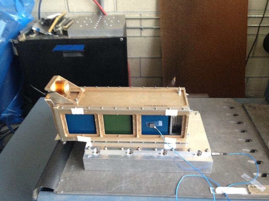
17 Appendix Appendix A: TestPODs and P-PODs 1U TestPOD 3U TestPOD 17
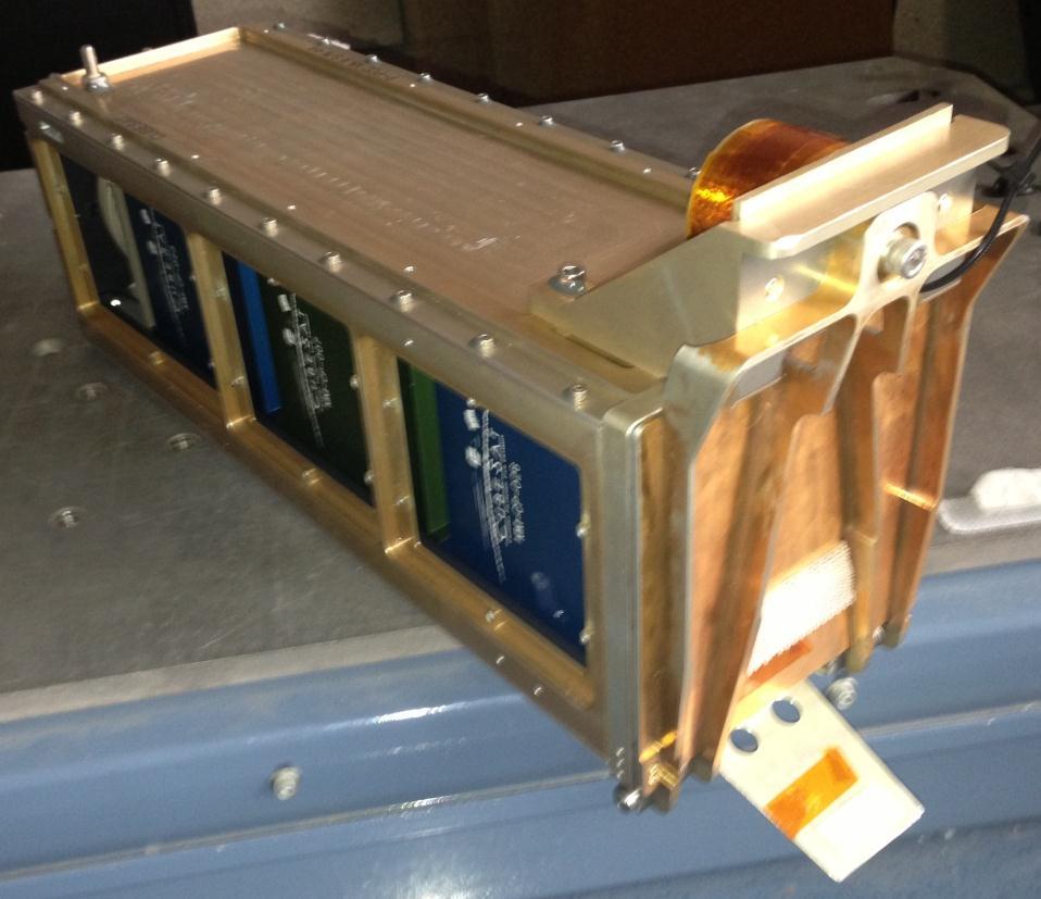
18 P-POD 18

19 Appendix B: Finite Element Analysis of Aluminum CubeSat Mass Model A normal modes solution (solution 103) was run in NX/NASTRAN on a finite element model (FEM) of the CubeSat mass model to obtain the frequency of the first resonant peak. If the peak is over 2,000 Hz, the mass model can be modeled as rigid for the analysis in this paper. The FEM was created out of 3D Hex elements with the material properties of aluminum 6061-T6 (elastic modulus of 10.1e6 psi, density of 0.1 pounds per cubic inch and a Poisson s ratio of 0.3). There were no constraints on the FEM to obtain a worst case first mode. The figure below shows the first mode of the CubeSat mass model (that is not a rigid-body mode) at 2,160 Hz. The mesh is included in the figure. A convergence study was performed to ensure enough degrees of freedom were used to in the FEM of the CubeSat mass model. The convergence study shows that, at 124,984 degrees of freedom, the eigenvalues sufficiently converged. This FEA study shows that the CubeSat mass model can be modeled as rigid inside the deployer from Hz. 19

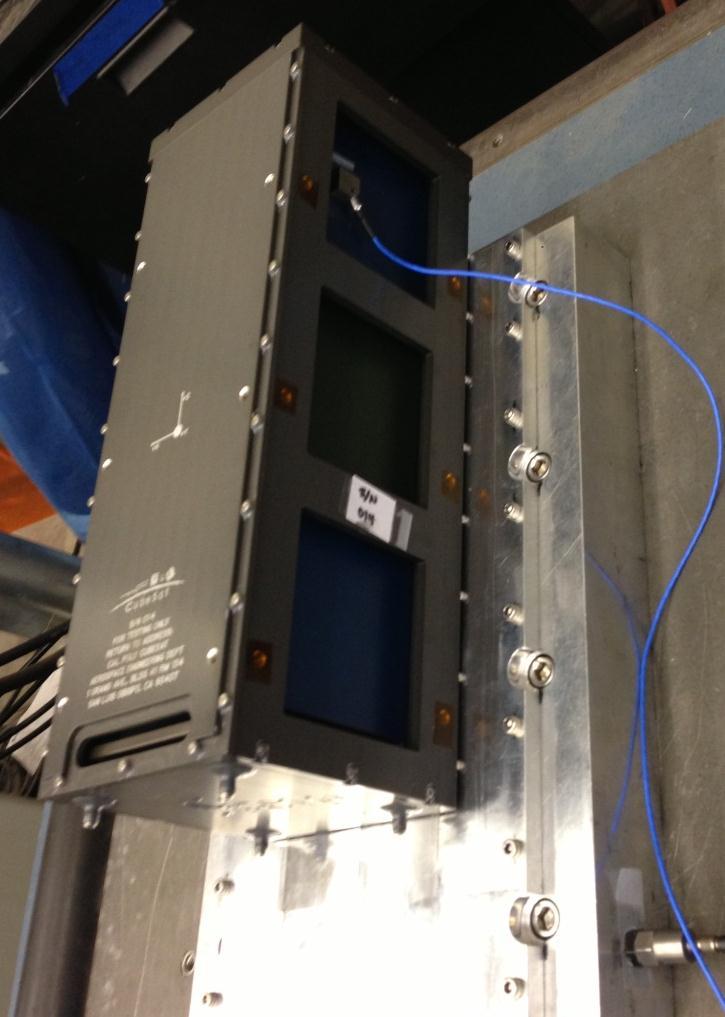
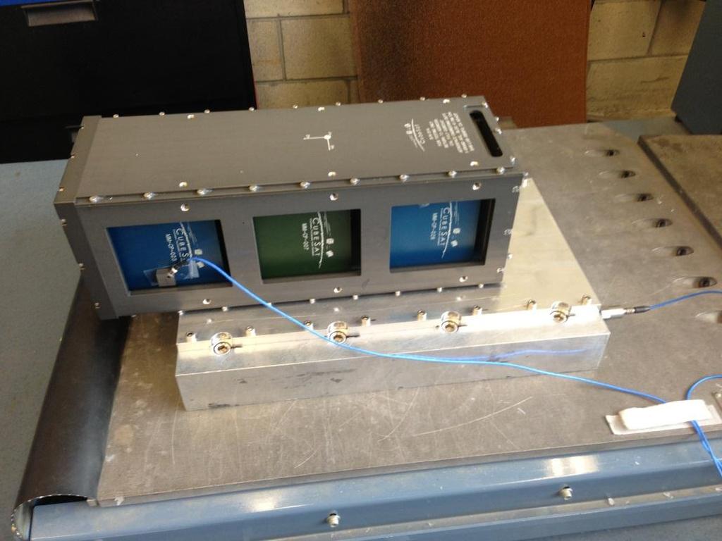
20 Appendix C: Test Setups for Baseline Characterization Test # Deployer Axis 1 1U TestPOD X 2 1U TestPOD Z 3-1 3U TestPOD X 3-2 3U TestPOD X 3-3 3U TestPOD X 4-1 3U TestPOD Z 4-2 3U TestPOD Z 4-3 3U TestPOD Z 5-1 P-POD X 5-2 P-POD X 6-1 P-POD Z 6-2 P-POD Z Test 1 20

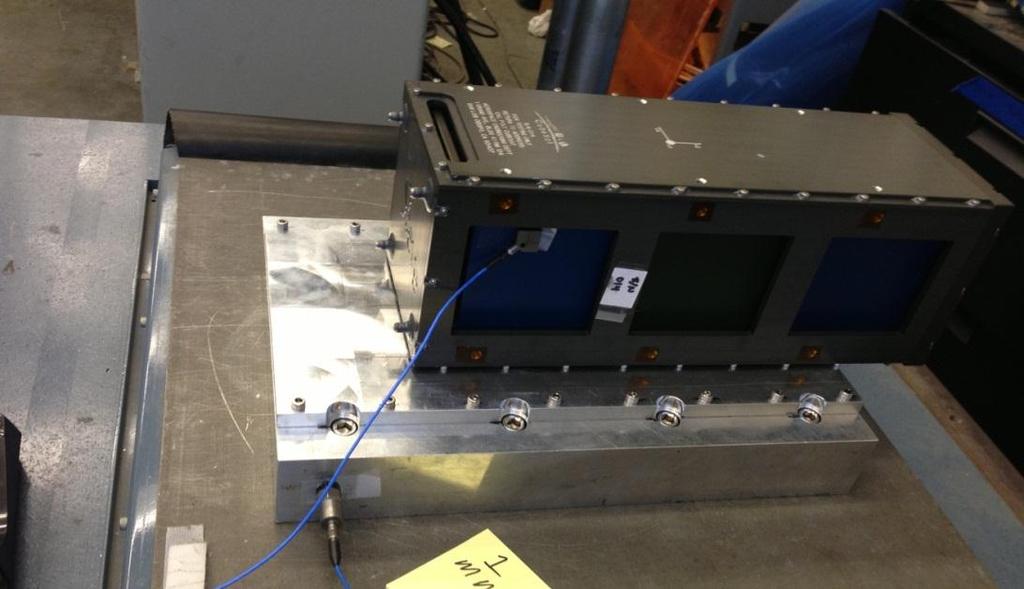
21 Test 2 Test 3 21

22 Test 3-2 Test

23 Test 4-1 Test

24 Test 4-3 Test

25 Test 5-2 Test

26 Test
Improving Launch Vibration Environments for CubeSats
 Improving Launch Vibration Environments for CubeSats Dave Pignatelli California Polytechnic State University, San Luis Obispo Small Satellite Conference, Logan, Utah August 8th, 2017 1 CubeSat Launch Environments
CubeSat Test Pod User s Guide Revision IV June, 2005
 Contacts: CubeSat Test Pod User s Guide Revision IV June, 2005 Cal Poly, San Luis Obispo Stanford University Prof. Jordi Puig-Suari Prof. Bob Twiggs, Director Aerospace Engineering Dept. Space Systems
Test Pod User s Guide
 Document Classification X Public Domain ITAR Controlled Internal Only Test Pod User s Guide Revision Date Author Change Log 6 11/6/2006 Jonathan Brown Moved to standard document format 1 of 6 1 Introduction
Methods to predict fatigue in CubeSat structures and mechanisms
 Methods to predict fatigue in CubeSat structures and mechanisms By Walter Holemans (PSC), Floyd Azure (PSC) and Ryan Hevner (PSC) 08-09 August 2015 12th Annual Summer CubeSat Developers' Workshop 08-09
CubeSat Design Specification
 Document Classification X Public Domain ITAR Controlled Internal Only CubeSat Design Specification (CDS) Revision Date Author Change Log 8 N/A Simon Lee N/A 8.1 5/26/05 Amy Hutputanasin Formatting updated.
MODEL MODIFICATION OF WIRA CENTER MEMBER BAR
 MODEL MODIFICATION OF WIRA CENTER MEMBER BAR F.R.M. Romlay & M.S.M. Sani Faculty of Mechanical Engineering Kolej Universiti Kejuruteraan & Teknologi Malaysia (KUKTEM), Karung Berkunci 12 25000 Kuantan
Modal Analysis and Vibration Test of NASA MSFC Shaker Table
 Washington University in St. Louis Washington University Open Scholarship Mechanical Engineering and Materials Science Independent Study Mechanical Engineering & Materials Science 11-11-2018 Modal Analysis
Poly Picosatellite Orbital Deployer Mk. III Rev. E User Guide
 The CubeSat Program California Polytechnic State University San Luis Obispo, CA 93407 X Document Classification Public Domain ITAR Controlled Internal Only Poly Picosatellite Orbital Deployer Mk. III Rev.
Filling in the MIMO Matrix Part 2 Time Waveform Replication Tests Using Field Data
 Filling in the MIMO Matrix Part 2 Time Waveform Replication Tests Using Field Data Marcos Underwood, Russ Ayres, and Tony Keller, Spectral Dynamics, Inc., San Jose, California There is currently quite
Summary. ESPA 6U Mount (SUM) overview SUM qualification status Future SUM enhancements Moog CSA adapters and ESPA family
 overview SUM qualification status Future SUM enhancements Moog CSA adapters and ESPA family") Summary ESPA 6U Mount (SUM) overview SUM qualification status Future SUM enhancements Moog CSA adapters and ESPA family 1 CubeSat Summer Workshop 11 August 2012 ESPA Six-U Mount SUM Adapter with ESPA standard
Summary ESPA 6U Mount (SUM) overview SUM qualification status Future SUM enhancements Moog CSA adapters and ESPA family 1 CubeSat Summer Workshop 11 August 2012 ESPA Six-U Mount SUM Adapter with ESPA standard
CHAPTER 5 FAULT DIAGNOSIS OF ROTATING SHAFT WITH SHAFT MISALIGNMENT
 66 CHAPTER 5 FAULT DIAGNOSIS OF ROTATING SHAFT WITH SHAFT MISALIGNMENT 5.1 INTRODUCTION The problem of misalignment encountered in rotating machinery is of great concern to designers and maintenance engineers.
SPD 1004 QM Vibration Testing
 SPD 1004 QM Vibration ing Document Author(s): Jehyuck Shin karamel_bro@khu.ac.kr Responsible Engineer(s): Seongwhan Lee Jungho Lee swhan@khu.ac.kr overthewater@khu.ac.kr Page 1/39 Revision History Revision
2015 HBM ncode Products User Group Meeting
 Looking at Measured Data in the Frequency Domain Kurt Munson HBM-nCode Do Engineers Need Tools? 3 What is Vibration? http://dictionary.reference.com/browse/vibration 4 Some Statistics Amplitude PDF y Measure
CubeSats: From Launch to Deployment Necessity for a standard.
 1 Necessity for a standard. Creation of a standard to facilitate the design process of small satellites. Deployment system to support the standard. Safe and reliable. Efficient and cost effective. Versatile.
An Alternative to Pyrotechnic Testing For Shock Identification
 An Alternative to Pyrotechnic Testing For Shock Identification J. J. Titulaer B. R. Allen J. R. Maly CSA Engineering, Inc. 2565 Leghorn Street Mountain View, CA 94043 ABSTRACT The ability to produce a
David M. Klumpar Keith W. Mashburn Space Science and Engineering Laboratory Montana State University
 Developing the Explorer-1 [PRIME] Satellite for NASA s ELaNa CubeSat Launch Program David M. Klumpar Keith W. Mashburn Space Science and Engineering Laboratory Montana State University Outline E1P Mission
CP7 ORBITAL PARTICLE DAMPER EVALUATION
 CP7 ORBITAL PARTICLE DAMPER EVALUATION Presenters John Abel CP7 Project Lead & Head Electrical Engineer Daniel Walker CP7 Head Software Engineer John Brown CP7 Head Mechanical Engineer 2010 Cubesat Developers
Coach Class to Orbit: the NPS CubeSat Launcher
 Calhoun: The NPS Institutional Archive Faculty and Researcher Publications Faculty and Researcher Publications Collection 2009-08 Coach Class to Orbit: the NPS CubeSat Launcher Hicks, Christina http://hdl.handle.net/10945/37306
MXR7202G/M. Low Cost, Low Noise ±2 g Dual Axis Accelerometer with Ratiometric Analog Outputs
 FEATURES Low cost Resolution better than 1 mg Dual axis accelerometer fabricated on a monolithic CMOS IC On chip mixed signal processing No moving parts; No loose particle issues >50,000 g shock survival
Interplanetary CubeSat Launch Opportunities and Payload Accommodations
 Interplanetary CubeSat Launch Opportunities and Payload Accommodations Roland Coelho, VP Launch Services Tyvak Nano-Satellite Systems Inc. +1(805) 704-9756 roland@tyvak.com Partnered with California Polytechnic
6U CubeSat Design Specification Revision 1.0
 X Document Classification Public Domain 6U CubeSat Design Specification Revision 1.0 (CP-6UCDS-1.0) Page 1 CHANGE HISTORY LOG Effective Date Revision Description of Changes 04/20/16 X1 Provisional release
CUBESAT P-Pod Deployer Requirements
 CUBESAT P-Pod Deployer Requirements May 2002 Authors: Isaac Nason Michelle Creedon Nick Johansen Introduction The CubeSat program is a joint effort between Cal Poly and Stanford Universities to develop
FLUTTER CONTROL OF WIND TUNNEL MODEL USING A SINGLE ELEMENT OF PIEZO-CERAMIC ACTUATOR
 24 TH INTERNATIONAL CONGRESS OF THE AERONAUTICAL SCIENCES FLUTTER CONTROL OF WIND TUNNEL MODEL USING A SINGLE ELEMENT OF PIEZO-CERAMIC ACTUATOR Naoki Kawai Department of Mechanical Engineering, University
Module 4 TEST SYSTEM Part 2. SHAKING TABLE CONTROLLER ASSOCIATED SOFTWARES Dr. J.C. QUEVAL, CEA/Saclay
 Module 4 TEST SYSTEM Part 2 SHAKING TABLE CONTROLLER ASSOCIATED SOFTWARES Dr. J.C. QUEVAL, CEA/Saclay DEN/DM2S/SEMT/EMSI 11/03/2010 1 2 Electronic command Basic closed loop control The basic closed loop
A study of Vibration Analysis for Gearbox Casing Using Finite Element Analysis
 A study of Vibration Analysis for Gearbox Casing Using Finite Element Analysis M. Sofian D. Hazry K. Saifullah M. Tasyrif K.Salleh I.Ishak Autonomous System and Machine Vision Laboratory, School of Mechatronic,
Experimental investigation of crack in aluminum cantilever beam using vibration monitoring technique
 International Journal of Computational Engineering Research Vol, 04 Issue, 4 Experimental investigation of crack in aluminum cantilever beam using vibration monitoring technique 1, Akhilesh Kumar, & 2,
IADS Frequency Analysis FAQ ( Updated: March 2009 )
") IADS Frequency Analysis FAQ ( Updated: March 2009 ) * Note - This Document references two data set archives that have been uploaded to the IADS Google group available in the Files area called; IADS Frequency
IADS Frequency Analysis FAQ ( Updated: March 2009 ) * Note - This Document references two data set archives that have been uploaded to the IADS Google group available in the Files area called; IADS Frequency
Recent System Developments for Multi-Actuator Vibration Control
 Recent System Developments for Multi-Actuator Vibration Control Marcos A. Underwood, Tu tuli Enterprises, San Jose, California Tony Keller, Spectral Dynamics Corporation, San Marcos, California This article
Studies on free vibration of FRP aircraft Instruments panel boards
 89 Studies on free vibration of FRP aircraft Instruments panel boards E. Chandrasekaran Professor in Dept. of Civil Engineering, Crescent Engineering College 648 India. e-mail: sekharan@vsnl.net and K.
Laboratory Test of Vibration of Micro/Nano Satellite for Environment Test Standardization
 Laboratory Test of Vibration of Micro/Nano Satellite for Test Standardization Amgalanbat Batsuren, Toru Hatamura, Hirokazi Masui, Mengu Cho Interaction Kyushu Institute of Technology 5 th Nano Satellite
TKR Protoflight Dynamic Test Readiness Review
 TKR Protoflight Dynamic Test Readiness Review Mike Opie Mike Opie Eric Roulo Eric Roulo mikeopie@slac.stanford.edu mikeopie@slac.stanford.edu eroulo@slac.stanford.edu eroulo@slac.stanford.edu LAT-TD-05386
(i) Sine sweep (ii) Sine beat (iii) Time history (iv) Continuous sine
 Sine sweep (ii) Sine beat (iii) Time history (iv) Continuous sine") A description is given of one way to implement an earthquake test where the test severities are specified by the sine-beat method. The test is done by using a biaxial computer aided servohydraulic test
A description is given of one way to implement an earthquake test where the test severities are specified by the sine-beat method. The test is done by using a biaxial computer aided servohydraulic test
CubeSat Standard Updates
 CubeSat Standard Updates Justin Carnahan California Polytechnic State University April 25, 2013 CubeSat Developers Workshop Agenda The CubeSat Standard CDS Rev. 12 to Rev. 13 Changes The 6U CubeSat Design
CHAPTER 6 INTRODUCTION TO SYSTEM IDENTIFICATION
 CHAPTER 6 INTRODUCTION TO SYSTEM IDENTIFICATION Broadly speaking, system identification is the art and science of using measurements obtained from a system to characterize the system. The characterization
The Air Bearing Throughput Edge By Kevin McCarthy, Chief Technology Officer
 159 Swanson Rd. Boxborough, MA 01719 Phone +1.508.475.3400 dovermotion.com The Air Bearing Throughput Edge By Kevin McCarthy, Chief Technology Officer In addition to the numerous advantages described in
Separation of Sine and Random Com ponents from Vibration Measurements
 Separation of Sine and Random Com ponents from Vibration Measurements Charlie Engelhardt, Mary Baker, Andy Mouron, and Håvard Vold, ATA Engineering, Inc., San Diego, California Defining sine and random
EE 560 Electric Machines and Drives. Autumn 2014 Final Project. Contents
 EE 560 Electric Machines and Drives. Autumn 2014 Final Project Page 1 of 53 Prof. N. Nagel December 8, 2014 Brian Howard Contents Introduction 2 Induction Motor Simulation 3 Current Regulated Induction
GEM Student Tutorial: Cubesats. Alex Crew
 GEM Student Tutorial: Cubesats Alex Crew Outline What is a Cubesat? Advantages and disadvantages Examples of Cubesat missions What is a cubesat? Originally developed by California Polytechnic State University
Design and Evaluation of a Piezoelectric Actuator for Turning
 Design and Evaluation of a Piezoelectric Actuator for Turning Albert A. Espinoza 1, Luke J. Mayer 2, Paul V. Oberlin 3, Matthew Bement 4 1 Dept. of Mechanical Eng., University of Texas at Austin, Austin,
STEREO IMPACT Solar Energetic Particles Package (SEP) Dynamic Test Plan
 Dynamic Test Plan") 1 2 Jet Propulsion Laboratory 352G-WBT-0507 Interoffice Memorandum January 13, 2005 To: From: Subject: References: Distribution W. B. Tsoi STEREO IMPACT Solar Energetic Particles Package (SEP) Dynamic
1 2 Jet Propulsion Laboratory 352G-WBT-0507 Interoffice Memorandum January 13, 2005 To: From: Subject: References: Distribution W. B. Tsoi STEREO IMPACT Solar Energetic Particles Package (SEP) Dynamic
Lessons learned measuring 3U and 6U payload rotation and velocity when dispensed in reduced gravity environment
 Lessons learned measuring 3U and 6U payload rotation and velocity when dispensed in reduced gravity environment Floyd Azure, Ryan Hevner and Walter Holemans of Planetary Systems Corporation (PSC) 2303
Flight Unit S/N 002 Environmental Vibration Test Report. Dwg. No
 Rev. ECO Description Author Approved Date 01 32-261 Initial Release M. Smith 12-6-07 Flight Unit S/N 002 Environmental Vibration Test Report Dwg. No. 32-06050.0102 Revision 01 November 26, 2007 32-0605.0102
Preliminary study of the vibration displacement measurement by using strain gauge
 Songklanakarin J. Sci. Technol. 32 (5), 453-459, Sep. - Oct. 2010 Original Article Preliminary study of the vibration displacement measurement by using strain gauge Siripong Eamchaimongkol* Department
Model Correlation of Dynamic Non-linear Bearing Behavior in a Generator
 Model Correlation of Dynamic Non-linear Bearing Behavior in a Generator Dean Ford, Greg Holbrook, Steve Shields and Kevin Whitacre Delphi Automotive Systems, Energy & Chassis Systems Abstract Efforts to
Innovative Uses of the Canisterized Satellite Dispenser (CSD)
") Innovative Uses of the Canisterized Satellite Dispenser (CSD) By Walter Holemans (PSC), Ryan Williams (PSC), Andrew Kalman (Pumpkin), Robert Twiggs (Moorehead State University), Rex Ridenoure (Ecliptic
Innovative Uses of the Canisterized Satellite Dispenser (CSD) By Walter Holemans (PSC), Ryan Williams (PSC), Andrew Kalman (Pumpkin), Robert Twiggs (Moorehead State University), Rex Ridenoure (Ecliptic
NAVAL POSTGRADUATE SCHOOL THESIS
 NAVAL POSTGRADUATE SCHOOL MONTEREY, CALIFORNIA THESIS INTEGRATION AND ENVIRONMENTAL QUALIFICATION TESTING OF SPACECRAFT STRUCTURES IN SUPPORT OF THE NAVAL POSTGRADUATE SCHOOL CUBESAT LAUNCHER PROGRAM by
Revision C June 5, Author: Ryan Connolly
 The P-POD Payload Planner s Guide Revision C June 5, 2000 Author: Ryan Connolly P-POD Payload Planner s Guide: Revision B 5/15/00 2 of 19 1. INTRODUCTION The Space Development, Manufacturing & Integration
Amateur Radio and the CubeSat Community
 Amateur Radio and the CubeSat Community Bryan Klofas KF6ZEO bklofas@calpoly.edu Electrical Engineering Department California Polytechnic State University, San Luis Obispo, CA Abstract This paper will explore
Boom Stability Control Final Project Report
 Boom Stability Control Final Project Report By Michael Barnes Justin Carnahan Daniel Fluitt Alicia Johnstone Project Advisor: Dr. Mackin Instructor s Comments: Instructor s Grade: Date: Boom Stability
The Calculation of grms. QUALMARK: Accelerating Product Reliability WHITE PAPER
 WHITE PAPER QUALMARK: Accelerating Product Reliability WWW.QUALMARK.COM 303.254.8800 by Neill Doertenbach The metric of grms is typically used to specify and compare the energy in repetitive shock vibration
The Future for CubeSats Present and Coming Launch Opportunities 18th Annual AIAA / USU Conference on Small Satellites CubeSat Workshop
 The Future for CubeSats Present and Coming Launch Opportunities 18th Annual AIAA / USU Conference on Small Satellites CubeSat Workshop Presented By: Armen Toorian California Polytechnic State University
Experimental Modal Analysis of an Automobile Tire
 Experimental Modal Analysis of an Automobile Tire J.H.A.M. Vervoort Report No. DCT 2007.084 Bachelor final project Coach: Dr. Ir. I. Lopez Arteaga Supervisor: Prof. Dr. Ir. H. Nijmeijer Eindhoven University
SHAKER TABLE SEISMIC TESTING OF EQUIPMENT USING HISTORICAL STRONG MOTION DATA SCALED TO SATISFY A SHOCK RESPONSE SPECTRUM Revision C
 SHAKER TABLE SEISMIC TESTING OF EQUIPMENT USING HISTORICAL STRONG MOTION DATA SCALED TO SATISFY A SHOCK RESPONSE SPECTRUM Revision C By Tom Irvine Email: tom@vibrationdata.com March 12, 2015 The purpose
Capacitive Versus Thermal MEMS for High-Vibration Applications James Fennelly
 Capacitive Versus Thermal MEMS for High-Vibration Applications James Fennelly Design engineers involved in the development of heavy equipment that operate in high shock and vibration environments need
MIL-STD-202G SHOCK (SPECIFIED PULSE)
") SHOCK (SPECIFIED PULSE) 1. PURPOSE. This test is conducted for the purpose of determining the suitability of component parts and subassemblies of electrical and electronic components when subjected to
SHOCK (SPECIFIED PULSE) 1. PURPOSE. This test is conducted for the purpose of determining the suitability of component parts and subassemblies of electrical and electronic components when subjected to
CubeSat Advisors: Mechanical: Dr. Robert Ash ECE: Dr. Dimitrie Popescu 435 Team Members: Kevin Scott- Team Lead Robert Kelly- Orbital modeling and
 CubeSat Fall 435 CubeSat Advisors: Mechanical: Dr. Robert Ash ECE: Dr. Dimitrie Popescu 435 Team Members: Kevin Scott- Team Lead Robert Kelly- Orbital modeling and power Austin Rogers- Attitude control
MXD6235Q. Ultra High Performance ±1g Dual Axis Accelerometer with Digital Outputs FEATURES
 Ultra High Performance ±1g Dual Axis Accelerometer with Digital Outputs MXD6235Q FEATURES Ultra Low Noise 0.13 mg/ Hz typical RoHS compliant Ultra Low Offset Drift 0.1 mg/ C typical Resolution better than
9LEUDWLRQ 0HDVXUHPHQW DQG $QDO\VLV
 9LEUDWLRQ 0HDVXUHPHQW DQG $QDO\VLV l l l l l l l l Why Analysis Spectrum or Overall Level Filters Linear vs. Log Scaling Amplitude Scales Parameters The Detector/Averager Signal vs. System analysis BA
CUBESAT-TO-GROUND COMMUNICATION AND MOBILE MODULAR GROUND- STATION DEVELOPMENT
 CUBESAT-TO-GROUND COMMUNICATION AND MOBILE MODULAR GROUND- STATION DEVELOPMENT Dylan Ichikawa Department of Electrical Engineering University of Hawaii at Manoa Honolulu, HI 96822 ABSTRACT A mobile modular
Strategies for Successful CubeSat Development. Jordi Puig-Suari Aerospace Engineering Department Cal Poly, San Luis Obispo CEDAR Workshop July, 2009
 Strategies for Successful CubeSat Development Jordi Puig-Suari Aerospace Engineering Department Cal Poly, San Luis Obispo CEDAR Workshop July, 2009 1 Some CubeSat Facts Over 100 Developers Worldwide Including
AN ADAPTIVE VIBRATION ABSORBER
 AN ADAPTIVE VIBRATION ABSORBER Simon Hill, Scott Snyder and Ben Cazzolato Department of Mechanical Engineering, The University of Adelaide Australia, S.A. 5005. Email: simon.hill@adelaide.edu.au 1 INTRODUCTION
System identification studies with the stiff wing minimutt Fenrir Flight 20
 SYSTEMS TECHNOLOGY, INC 3766 S. HAWTHORNE BOULEVARD HAWTHORNE, CALIFORNIA 925-783 PHONE (3) 679-228 email: sti@systemstech.com FAX (3) 644-3887 Working Paper 439- System identification studies with the
Solution of Pipeline Vibration Problems By New Field-Measurement Technique
 Purdue University Purdue e-pubs International Compressor Engineering Conference School of Mechanical Engineering 1974 Solution of Pipeline Vibration Problems By New Field-Measurement Technique Michael
TCS3 SERVO SYSTEM: Proposed Design
 UNIVERSITY OF HAWAII INSTITUTE FOR ASTRONOMY 2680 Woodlawn Dr. Honolulu, HI 96822 NASA Infrared Telescope Facility TCS3 SERVO SYSTEM: Proposed Design.......... Fred Keske June 7, 2004 Version 1.2 1 INTRODUCTION...
Resonance Tube. 1 Purpose. 2 Theory. 2.1 Air As A Spring. 2.2 Traveling Sound Waves in Air
 Resonance Tube Equipment Capstone, complete resonance tube (tube, piston assembly, speaker stand, piston stand, mike with adapters, channel), voltage sensor, 1.5 m leads (2), (room) thermometer, flat rubber
Basic Electronics Learning by doing Prof. T.S. Natarajan Department of Physics Indian Institute of Technology, Madras
 Basic Electronics Learning by doing Prof. T.S. Natarajan Department of Physics Indian Institute of Technology, Madras Lecture 26 Mathematical operations Hello everybody! In our series of lectures on basic
Mode-based Frequency Response Function and Steady State Dynamics in LS-DYNA
 11 th International LS-DYNA Users Conference Simulation (3) Mode-based Frequency Response Function and Steady State Dynamics in LS-DYNA Yun Huang 1, Bor-Tsuen Wang 2 1 Livermore Software Technology Corporation
ABSTRACT INTRODUCTION
 COMPASS-1 PICOSATELLITE: STRUCTURES & MECHANISMS Marco Hammer, Robert Klotz, Ali Aydinlioglu Astronautical Department University of Applied Sciences Aachen Hohenstaufenallee 6, 52064 Aachen, Germany Phone:
ACOUSTIC MITIGATION POST-S3 UPDATE
 ACOUSTIC MITIGATION POST-S3 UPDATE Robert Schofield, University of Oregon AND MANY OTHERS 1 REDUCTION IN ACOUSTIC COUPLING SINCE S2 Red: AS_Q normal; Black: AS_Q with noise; Yellow & Orange: BSC7 mic March
INTELLIGENT ACTIVE FORCE CONTROL APPLIED TO PRECISE MACHINE UMP, Pekan, Pahang, Malaysia Shah Alam, Selangor, Malaysia ABSTRACT
 National Conference in Mechanical Engineering Research and Postgraduate Studies (2 nd NCMER 2010) 3-4 December 2010, Faculty of Mechanical Engineering, UMP Pekan, Kuantan, Pahang, Malaysia; pp. 540-549
Modal Parameter Identification of A Continuous Beam Bridge by Using Grouped Response Measurements
 Modal Parameter Identification of A Continuous Beam Bridge by Using Grouped Response Measurements Hasan CEYLAN and Gürsoy TURAN 2 Research and Teaching Assistant, Izmir Institute of Technology, Izmir,
NAVAL POSTGRADUATE SCHOOL
 NPS-SP-08-001 NAVAL POSTGRADUATE SCHOOL MONTEREY, CALIFORNIA STRUCTURAL DESIGN OF A NPS CUBESAT LAUNCHER by Felix Roßberg January 2008 Approved for public release; distribution is unlimited Prepared for:
System Inputs, Physical Modeling, and Time & Frequency Domains
 System Inputs, Physical Modeling, and Time & Frequency Domains There are three topics that require more discussion at this point of our study. They are: Classification of System Inputs, Physical Modeling,
ANALYSIS OF 3RD OCTAVE BAND GROUND MOTIONS TRANSMISSION IN SYNCHROTRON RADIATION FACILITY SOLARIS Daniel Ziemianski, Marek Kozien
 ANALYSIS OF 3RD OCTAVE BAND GROUND MOTIONS TRANSMISSION IN SYNCHROTRON RADIATION FACILITY SOLARIS Daniel Ziemianski, Marek Kozien Cracow University of Technology, Institute of Applied Mechanics, al. Jana
Spectrum Analysis: The FFT Display
 Spectrum Analysis: The FFT Display Equipment: Capstone, voltage sensor 1 Introduction It is often useful to represent a function by a series expansion, such as a Taylor series. There are other series representations
Flight Unit S/N 001 Environmental Vibration Test Report. Dwg. No
 Rev. ECO Description Author Approved Date 01 32-261 Initial Release M. Smith 12-6-07 Flight Unit S/N 001 Environmental Vibration Test Report Dwg. No. 32-06050.0101 Revision 01 December 8, 2007 32-0605.0101
Exam Signal Detection and Noise
 Exam Signal Detection and Noise Tuesday 27 January 2015 from 14:00 until 17:00 Lecturer: Sense Jan van der Molen Important: It is not allowed to use a calculator. Complete each question on a separate piece
Part 2: Second order systems: cantilever response
 - cantilever response slide 1 Part 2: Second order systems: cantilever response Goals: Understand the behavior and how to characterize second order measurement systems Learn how to operate: function generator,
Finite Element Analysis per ASME B31.3
 Brief Discussion: Split-Body 12in Butterfly valve, Ph: 520-265-3657 Page 1 of 13 Finite Element Analysis per ASME B31.3 Prepared by: Michael Rodgers, P.Eng. Date: July 16, 2010 Page 2 of 13 Section Headings:
MXD7210GL/HL/ML/NL. Low Cost, Low Noise ±10 g Dual Axis Accelerometer with Digital Outputs
 FEATURES Low cost Resolution better than 1milli-g at 1Hz Dual axis accelerometer fabricated on a monolithic CMOS IC On chip mixed signal processing No moving parts; No loose particle issues >50,000 g shock
Load Observer and Tuning Basics
 Load Observer and Tuning Basics Feature Use & Benefits Mark Zessin Motion Solution Architect Rockwell Automation PUBLIC INFORMATION Rev 5058-CO900E Questions Addressed Why is Motion System Tuning Necessary?
Resonance Tube Lab 9
 HB 03-30-01 Resonance Tube Lab 9 1 Resonance Tube Lab 9 Equipment SWS, complete resonance tube (tube, piston assembly, speaker stand, piston stand, mike with adaptors, channel), voltage sensor, 1.5 m leads
SmartSenseCom Introduces Next Generation Seismic Sensor Systems
 SmartSenseCom Introduces Next Generation Seismic Sensor Systems Summary: SmartSenseCom, Inc. (SSC) has introduced the next generation in seismic sensing technology. SSC s systems use a unique optical sensing
Dynamic Angle Estimation
 Dynamic Angle Estimation with Inertial MEMS Analog Devices Bob Scannell Mark Looney Agenda Sensor to angle basics Accelerometer basics Accelerometer behaviors Gyroscope basics Gyroscope behaviors Key factors
Fundamentals of Servo Motion Control
 Fundamentals of Servo Motion Control The fundamental concepts of servo motion control have not changed significantly in the last 50 years. The basic reasons for using servo systems in contrast to open
Making it Small. April 22-24, 24, Cal Poly Developers Workshop California State Polytechnic University San Luis Obispo, CA
 Making it Small April 22-24, 24, 2009 2009 Cal Poly Developers Workshop California State Polytechnic University San Luis Obispo, CA Prof. Bob Twiggs Bob.Twiggs@Stanford.Edu What started the miniaturization
Introduction to LIVM Accelerometers
 Introduction to LIVM Accelerometers Construction Low Impedance Voltage Mode (LIVM) accelerometers are designed to measure shock and vibration phenomena over a wide frequency range. They contain integral
Application of MEMS accelerometers for modal analysis
 Application of MEMS accelerometers for modal analysis Ronald Kok Cosme Furlong and Ryszard J. Pryputniewicz NEST NanoEngineering Science and Technology CHSLT Center for Holographic Studies and Laser micro-mechatronics
Quartz Lock Loop (QLL) For Robust GNSS Operation in High Vibration Environments
 For Robust GNSS Operation in High Vibration Environments") Quartz Lock Loop (QLL) For Robust GNSS Operation in High Vibration Environments A Topcon white paper written by Doug Langen Topcon Positioning Systems, Inc. 7400 National Drive Livermore, CA 94550 USA
Quartz Lock Loop (QLL) For Robust GNSS Operation in High Vibration Environments A Topcon white paper written by Doug Langen Topcon Positioning Systems, Inc. 7400 National Drive Livermore, CA 94550 USA
MTE 360 Automatic Control Systems University of Waterloo, Department of Mechanical & Mechatronics Engineering
 MTE 36 Automatic Control Systems University of Waterloo, Department of Mechanical & Mechatronics Engineering Laboratory #1: Introduction to Control Engineering In this laboratory, you will become familiar
Active Vibration Isolation of an Unbalanced Machine Tool Spindle
 Active Vibration Isolation of an Unbalanced Machine Tool Spindle David. J. Hopkins, Paul Geraghty Lawrence Livermore National Laboratory 7000 East Ave, MS/L-792, Livermore, CA. 94550 Abstract Proper configurations
Enhanced Resonant Inspection Using Component Weight Compensation. Richard W. Bono and Gail R. Stultz The Modal Shop, Inc. Cincinnati, OH 45241
 Enhanced Resonant Inspection Using Component Weight Compensation Richard W. Bono and Gail R. Stultz The Modal Shop, Inc. Cincinnati, OH 45241 ABSTRACT Resonant Inspection is commonly used for quality assurance
AGN 008 Vibration DESCRIPTION. Cummins Generator Technologies manufacture ac generators (alternators) to ensure compliance with BS 5000, Part 3.
 to ensure compliance with BS 5000, Part 3.") Application Guidance Notes: Technical Information from Cummins Generator Technologies AGN 008 Vibration DESCRIPTION Cummins Generator Technologies manufacture ac generators (alternators) to ensure compliance
Application Guidance Notes: Technical Information from Cummins Generator Technologies AGN 008 Vibration DESCRIPTION Cummins Generator Technologies manufacture ac generators (alternators) to ensure compliance
Dynamic Analysis & Correlation for Exhaust System
 Dynamic Analysis & Correlation for Exhaust System Xitian (Steve) Fang, Ciray Sam ArvinMeritor, 95 W 5 S, Columbus, IN71 ABSTRACT This paper emphasis on the systematic procedure for the FEA dynamic analysis
Advanced High-Frequency 6-DOF Vibration Testing Using the Tensor System
 Advanced High-Frequency 6-DOF Vibration Testing Using the Tensor System Joel Hoksbergen, Team Corporation 1 Abstract Commercially available vibration test systems able to reproduce and accurately control
Dynamic Vibration Absorber
 Part 1B Experimental Engineering Integrated Coursework Location: DPO Experiment A1 (Short) Dynamic Vibration Absorber Please bring your mechanics data book and your results from first year experiment 7
MXD6125Q. Ultra High Performance ±1g Dual Axis Accelerometer with Digital Outputs FEATURES
 Ultra High Performance ±1g Dual Axis Accelerometer with Digital Outputs MXD6125Q FEATURES Ultra Low Noise 0.13 mg/ Hz typical RoHS compliant Ultra Low Offset Drift 0.1 mg/ C typical Resolution better than
Very High Frequency Calibration of Laser Vibrometer up to 350 khz
 Very High Frequency Calibration of Laser Vibrometer up to 350 khz Requirements, Solutions and Traceability Dr. Martin Brucke, Frank Schulz There is simply no substitute for knowing what you re doing Jeff
ME scope Application Note 02 Waveform Integration & Differentiation
 ME scope Application Note 02 Waveform Integration & Differentiation The steps in this Application Note can be duplicated using any ME scope Package that includes the VES-3600 Advanced Signal Processing
SYSTEM IDENTIFICATION: A STUDY OF VARIOUS METHODS FOR CONTINUOUS SYSTEMS
 SYSTEM IDENTIFICATION: A STUDY OF VARIOUS METHODS FOR CONTINUOUS SYSTEMS Ayush Raizada, Vishnuvardhan Krishnakumar, Dr. P. M. Singru Abstract This paper addresses and evaluates the methods of system identification