SAFETY INFORMATION FOR USER
|
|
|
- Theodore Bennett
- 5 years ago
- Views:
Transcription

1 USER MANUAL
2
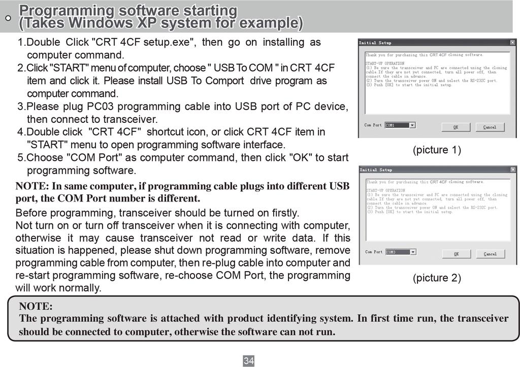
3 SAFETY INFORMATION FOR USER CRT transceiver is excellently designed with advanced technology. Please observe the following precautions to perform your obligation, prevent personal injury and ensure the safety of transceiver usage. 1. Keep the transceiver and accessories away from children. 2. Please do not try to open or modify the transceiver without permission, non-professionals process may also cause damage. 3. Please use assorted battery and charger to avoid damage. 4. Please use assorted antenna to ensure the communication distance. 5. Please do not expose the transceiver to long period of direct sunlight, nor place it close to heat appliances. 6. Please do not put the transceiver in excessively dusty or humid areas. 7. Do not use harsh chemicals, cleaning solvents to clean the transceiver. 8. Do not transmit without antenna. 9. When using this transceiver, we recommend transmitting for 1 minute then receiving for 4 minutes. Continuous transmitting for long time or working in high power will heat the back of the transceiver. Do not place the transceiver s hot back close to any surface of plastic. 10.If any abnormal odor or smoke detected coming from the transceiver, turn off the power and take off the battery pack and its case. Then contact local CRT dealers. NOTICE All tips as above also apply to the standard parts of CRT transceiver. If any spare parts fail to work, please contact local CRT dealers in time. If users use spare parts from other suppliers instead of CRT, the safety and performance of the transceiver can't be guaranteed.
4 THANK YOU FOR YOUR PURCHASE! Features include 199 memory channels, memory banks, UV-VV-UU modes, dual PTT(programmable), 51 groups CTCSS encode/decode, 1 group user-defined CTCSS encode/decode, 1024 groups DCS encode/ decode, plus 2Tone, 5Tone and DTMF encode/decode. Unique features include the ability to adjust squelch level on-the-ly, display both channel mode and frequency mode at the same time, skip interfering channels while scanning and choose single or dual PTT buttons. The frequency of named channels can be easily displayed and the scanning rate of channels is adjustable via software. Dual standby, dual display, dual receive channel, cross-band repeater functions, frequecny hopping functions(fhss).
5 TABLE OF CONTENTS CONTENS...01 Contents STANDARD ACCESSORIES/ADDITIONAL ACCESSORIES Standard Accessories Additional Accessories OPERATION MODE BATTERY INFORMATION How to Charge Charging Prompt GETTING ACQUAINTED LCD Display BASIC OPERATIONS...10 Switch between Main band and Sub band Switch between Channel mode and VFO mode Channel Adjusting Frequency Adjusting Frequency Input by Keypad Channel Input by Keypad Squelch Off Momentary / Squelch Off Receiving Transmitting Emergency Alarm Side Key [PF1] function instruction Side key [PF2] function instruction Edit channel
6 TABLE OF CONTENTS Delete channel Programming scan SHORTCUT OPERATIONS Turn On/ Off FM Radio Add/Cancel Optional signal decode function CTCSS/DCS Scan Offset Frequency Direction Setup Frequency/Channel Scan Channel Scan Skip Frequency Reverse TX Power selection Talk Around function DTMF code Transmit and Enquiry Keypad lock Single-band Switching CTCSS/DCS Encode and Decode Cross-Band Repeater Function Menu Setup Senior Function Operations Display Mode Setup Resume Factory Default Cloning Cable Memory Bank (Version D ) Memory Bank Switch Memory Bank Exit Bank Linking
7 TABLE OF CONTENTS Programming software starting (Takes Windows XP system for example) TECHNICAL SPECIFICATION ATTACHED CHART CTCSS Frequency Chart DCS Frequency Chart
8 STANDARD ACCESSORIES/ADDITIONAL ACCESSORIES Standard Accessories Antenna Li-ion Battery Battery Charger AC Adaptor Belt Clip Additional Accessories USB Programming Cable Earphone Car Charger Clone cable Handheld Microphone Battery Pack for Car Charger 04
9 OPERATION MODE 1. How to choose a operation Mode: A. By programming software: In PC software's "General Setting" menu to choose "Display Mode", channel mode works as Professional transceiver, other two modes as Amateur transceiver. B. By manual setup: Please refer to "Display Mode". 2. Amateur Mode: Under this mode, press key can switch between Channel mode and VFO mode. A. Frequency + Channel mode: When set display as "FREQ", the radio enters Frequency +Channel mode, new setting of channel operation and shortcut operation can be temporarily used by user. Once the radio is turned off or switched to another channel, the temporary setting will be erased and back to initial settings B. Channel+Name Tag Mode: When set display as "NAME", it enters Channel+Name Tag Mode. the LCD will display corresponding channel name when the current channel is edited with name. Otherwise, it will display frequency + channel. C. VFO Mode(Frequency mode): This mode shows only frequency on the display. Shortcut operation and Channel setting will be changed and stored as the latest value permanently. Once the radio is turned off or changed to new VFO frequency, the value is remained until next change. 3. Professional Mode: when set as CH mode, all radio functions shall be set by PC software, besides scan, DTMF encode, keypad lock. In CH mode, users can't return to amateur mode by menu function. 05
10 BATTERY INFORMATION How to Charge 1. Plug the AC adaptor into the AC outlet, then plug the cable of AC adaptor into the DC jack, the indicator lights orange for 1s and turns into GREEN---waits to charge. 2. Slide the battery or transceiver with battery into the charger; make sure the battery terminals are in contact with the charging terminals. LED turns into twinkling RED---pre-charging begins. 3. Pre-charging for about 5 minutes, LED twinkles stop then charging begins. 4. It takes about 5.5 hours to fully charge the battery, when LED turns into GREEN full charged. 5. Charging Process: Status Standby (self-examine orange lights 1second when power on) Pre-charging (pre-charging stage) Charging (charge in constant currency) Full charged (charge in constant voltage) LED Ac Input Green light Red light twinkles for about 5 minutes RED light lightens for about 5.5 hours Green light 06
11 BATTERY INFORMATION 6. LED Indicator: STATUS LED self-examine when power on (No battery) Pre-charging Charge normally Orange Red light twinkles Green Red (for 1 second) for 5 minutes Full Charged Green NOTE: Trouble means battery heating, battery short-circuit or charger short-circuit. Trouble Red twinkles for a long time Charging Prompt 1. Self- examination: When charging, ORANGE light twinkles for 1 second and goes out. That means the charger has passed its self-examination and it can charge the battery normally. If the light remains orange or the red light twinkles, it means the charger can not pass its self-examination or charge the battery. 2. Trickle pre-charging: When the battery has been inserted into the charger and red light twinkles, which means the remnant voltage is low, the charger trickle charges the battery (pre-charging status), until the battery reaches a certain electric quantity, then the charger automatically turns to normal charging. If the red light stops twinkling, it means the remnant voltage meets a certain electric quantity, and the charger will charge the battery normally. NOTE:The time for Trickle pre-charging should not exceed 30 min. If after 30 min, the red indicator is still twinkling, it means it is unable to charge battery. Please kindly check battery and charger. 07
12 GETTING ACQUAINTED LCD Display On LCD display screen, you will see various icons which stand for the selected functions and sometimes you may forget the meaning of them. Here you will find the following table extremely useful. Frequency Reverse Offset Frequency DCS Optional Signaling CTCSS FUNC Icon The arrow points to main channel FM radio TX Power VOX Function Scan Skip Narrow band Battery Capacity Function Menu Number, Channel Number FM Channel Number channel Number Keypad Lock Busy Channel NOTE: Battery capacity indicator(full) Battery capacity remnant No power, replace battery pack or charge battery Real time display receiving signal strength/power Indicator 08
13 GETTING ACQUAINTED 1 Antenna 2 Selector Knob 1 3 Power/Volume switch 4 Emergency Aarm 5 6 TX/RX indicator LCD display Keypad PTT key PF1 key SP MIC DCIN PF2 key J Car charging port BAND MSK 13 Single-band Switching 14 Memory Bank 09
14 BASIC OPERATIONS Switch between Main band and Sub band Under standby state, press key to switch between Main band and Sub band. Arrow indicates the Main band. Switch between Channel mode and VFO mode Under standby state, press mode (VFO). Channel Adjusting key to set main band as Channel mode or frequency With transceiver in Channel mode or FM radio channel mode, rotate channel switch to adjust channel. Rotate channel switch clockwise to increase channel number, anticlockwise to decrease channel number. NOTE: In transceiver mode, arrow directs the main band channel. Rotating channel switch will step through only programmed (saved) channels. Unsaved channels will be skipped. Frequency Adjusting With transceiver in VFO mode or FM radio frequency mode, rotate channel switch to adjust frequency. Rotate channel switch clockwise to increase frequency, anticlockwise to decrease frequency. Frequency change depends on chosen frequency step. 10
15 BASIC OPERATIONS NOTE: Channel step:2.5k, 5K, 6.25K, 10K, 12.5K, 20K, 25K, 30K and 50KHz in total 9 for optional. FM radio step frequency is 50K. Frequency Input by Keypad Under frequency mode or FM radio frequency mode, you can directly enter frequency through keypad. 1. When your transceiver is under Channel mode, press key to switch into VFO. NOTE: When the transceiver is under Channel mode, it shows current channel number on the right of main frequency. 2. Enter the desired frequency by keypad. NOTE: The frequency input of main channel or FM radio is relevant to the stepping and transceiver frequency range. If frequency setup is beyond range or not matching with step size, the input is unavailable. Under the FM radio mode, the frequency step size input by numeric keys is 100k. Channel Input by Keypad Under channel mode of transceiver or FM radio, you can switch to desired channel by entering three numbers ( ). If the entered channel is not a saved channel, the transceiver will emit beep to prompt wrong input and return to current channel. For example, entering 001 is channel 1, 030 is channel 30, 125 is channel 125. Squelch Off Momentary / Squelch Off Side key [PF2] can be setup for Squelch off Momentary or Squelch off function by programming software. 11
16 BASIC OPERATIONS 1. Squelch off: Press [PF2] key, squelch circuit is not mute, back-ground noise can be heard. Press [PF2] key again, squelch circuit is mute. 2. Squelch off Momentary: Press and hold [PF2] key, squelch circuit is not mute, back-ground noise can be heard. Release [PF2] key, squelch circuit is mute. NOTE: The above functions are only available after [PF2] key setup in programming software. When in channel mode, opening squelch will show the frequency of the channel. Receiving When your transceiver is called by other party, green or blue LED light will be on, LCD backlight will be on at the same time, and the arrow icon will flash, you can hear the calling. NOTE: You may not receive the calling when your transceiver is set at high squelch level. If current channel is programmed with decode signal, only the same signaling call can be heard. Transmitting According to [PF2] key setup in programming software, hold [PF2] key to monitor the channel to ensure it is not busy, press PTT key and talk to speaker. Please keep the distance between mouth and speaker to be 2.5-5CM, speak in normal tone to get the best acoustic fidelity. NOTE: When press and hold PTT key, transceiver is transmitting if the red LED light is on, release PTT key to receive calls. 12
17 BASIC OPERATIONS Emergency Alarm Under standby state, press and hold [PF1] key (when programmed for ALARM function) or press the Emer -gency Alarm keyuntil LCD displays "ALARM", Emergency alarm function is started. This transceiver has 4 Alarm modes that can be setup in programming software. Power off transceiver to exit Alarm. Side Key [PF1] function instruction [PF1] key can be setup in for below functions: 1. VOLT: Battery capacity inquiry: Under standby, press [PF1] key, LCD displays current battery capacity, press this key again to exit. 2. CALL: Transmit the prestored DTMF/5TONE Encode signal in channel. 3. FHSS(Version D): Frequency hopping function. Press [PF1] key, turn on frequency hopping function, LCD display "FHSS", transceiver will communicate in pre-set hopping frequency range. Note: Receiver and Sender must have same hopping frequency, and must setup MSK decode signalling. 4. ALARM: Long pressing [PF1] key, LCD display "ALARM", transceiver will enable the preset alarm function. 5. SUBPTT: Press [PF1] key, transceiver will transmit on sub-band frequency. 6. Transmit tone pulse frequency: Press and hold PTT key, then press [PF1] key to transmit selected tone pulse frequency. NOTE: The tone pulse frequency can be set to 1750Hz, 1450Hz, 1000Hz or 2100Hz in programming software. 13
18 BASIC OPERATIONS Side key [PF2] function instruction 1. Squelch off: Press [PF2] key, squelch circuit is not mute, back-ground noise can be heard. Press [PF2] key again, squelch circuit is mute. 2. Squelch off Momentary: Press and hold [PF2] key, squelch circuit is not mute, back-ground noise can be heard. Release [PF2] key, squelch circuit is mute. 3. Transmit DTMF/5TONE/2TONE signaling: Press and hold [PTT] key, then press [PF2] key to transmit selected DTMF/5TONE/2TONE signaling. 4. Press and hold [PF2] key to turn on transceiver, until transceiver emits "DU" beep, transceiver enter into general functions setup. Edit channel 1. Under frequency mode (VFO), enter desired frequency and settings, press key, the top left corner of LCD displays " " icon, press key to switch into channel mode, channel number flashes. 2. Rotate channel switch to select desired editing channel number. 3. Press key, the top left corner of LCD displays " " icon, press and hold key until transceiver emits "DUDU" beep, channel is stored successfully. Delete channel 1. Under standby state, press key, the top left corner of LCD displays " " icon, press key to switch into channel mode, channel number flashes. 14
19 BASIC OPERATIONS 2. Rotate channel switch to select desired deleting channel number. 3. Press key, the top left corner of LCD displays " " icon, press and hold key until transceiver emits "DUDU" beep and clear up frequency information of current channel, deletion is successful. NOTE: This process can be applied for deleting FM radio channels. Programming scan Setup the frequency of L1 channel, U1 channel, L2 channel and U2 channel will realize VFO frequency scanning border limited. L1 & L2 is starting frequency, U1 & U2 is end frequency. When VFO frequency between L1~ U1 or L2 ~ U2, transceiver will scan frequencies between L1 ~ U1 or L2 ~ U2. When VFO frequency is lower than L1 or L2, transceiver will scan frequencies higher than L1 or L2. When VFO frequency is higher than U1 or U2, transceiver will scan frequencies higher than U1 or U2. 1. In VFO mode, enter desired frequency and relative setup, press key, the top left corner of LCD displays " " icon, then press key switch into channel mode, channel number flashes 2. Rotate channel switch to choose desired channel number. 3. Press key, the top left corner of LCD displays " " icon, then press key until transceiver emits "DUDU" beep, channels are saved successfully. NOTE: To make this setup, L1 and U1 must in same frequency band. L2 and U2 must in same band. 15
20 SHORTCUT OPERATIONS Turn On/ Off FM Radio This radio has FM/AM/SW/LW total 4 FM radio bands. Press key then press key to turn on FM radio, later press key then press key to switch between FM/AM/SW/LW band, press key will mute /un-mute FM radio. FM: 64~108MHz(RX) (100 memory channels CH00~CH99 AM: 118~136MHz(RX) (100 memory channels CH00~CH99 SW: 2.3~29.99MHz(RX) LW: 0.52~1.71MHz(RX) Note:AM/SW/LW require special antenna. When AM is on, the downside RX channel is occupied. Add/Cancel Optional signal decode function Under standby state, press key, the top left corner of LCD displays " " icon, press key. 1. LCD display " DTMF" and "T " icon, DTMF signal add in current channel. 2. Repeat above operation, LCD display " 5TONE" and "T " icon, 5TONE signal add in current channel. 3. Repeat above operation, LCD display " 2TONE" and "T " icon, 2TONE signal add in current channel. 4. Repeat above operation, LCD display " MSK" and "T " icon, MSK signal add in current channel. 5. Repeat above operation, LCD display " OFF", the "T " icon disappear, no optional signal in current channel. NOTE: When this function is on, user must setup No.7 menu to be TONE option, then DTMF/5TONE/2TONE/ MSK can be used. 16
21 SHORTCUT OPERATIONS CTCSS/DCS Scan Press key, the top left corner of LCD displays " " icon, press key to enter into CTCSS/DCS scan. Under this state, rotate channel switch to change scan direction. When scan the matching CTCSS/DCS signaling, it will stay 5seconds and MSK then go on scanning. Press any other keys except,, key to exit. NOTE: This function is invalid when transceiver works in professional mode or the arrow directed channel no setting CTCSS/DCS signaling. In current channel, if signaling set as CTCSS, it will scan CTCSS, if sets as DCS, it will scan DCS. Offset Frequency Direction Setup Under standby state, press key, the top left corner of LCD displays " " icon, press key to choose offset frequency direction. There are 3 options, Positive offset, Minus offset, shut off offset. 1. (+) Positive offset: Indicates TX frequency is higher than RX frequency. When enable reverse function, the RX frequency is higher than TX frequency. 2. (-) Minus offset: Indicates TX frequency is lower than RX frequency. When enable reverse function, the RX frequency is lower than TX frequency. 3. None: Indicates shut offset off. Under frequency mode (VFO) or channel mode, press key then press key to choose positive offset direction(+), minus offset direction (-), shut offset off one by one (Please refer to offset frequency setup). NOTE: This function is unavailable in professional transceiver mode. 17
22 SHORTCUT OPERATIONS Frequency/Channel Scan Under corresponding mode, press key, the top left corner of LCD displays " " icon, then press key to start frequency scan or channel scan. 1. Frequency Scan Under VFO mode, frequency scan is available. This function is used for monitoring signal of various communication frequency by transceiver step setup, press numeric key or key to exit. 2. Channel Scan Under channel mode, this function is used for monitoring signal of each channel in this mode. Press numeric key or key to exit. NOTE: Frequency scan is of all bands scan, it scans upwards as your STEPPING setting. In channel scan, the skipped channel is not in the line of scanning. Scan upwards as per channel no. (please refer to channel scan skip). Frequency/channel scan can change scan direction by rotating channel switch, when find a matching carrier wave and signaling, the transceiver will stay 5 seconds then go on scanning. (Please refer to scan setup) If turn off radio in scan mode, when re-power on, radio will resume scanning automatically. Channel Scan Skip Under channel mode, press key, the top left corner of LCD displays " " icon, then press key to set current arrow directed channel as Channel scan skip. Repeat above operation to cancel channel scan skip. 1. LCD displayed "S " means the current channel will not be scanned. 2. " S " icon disappeared means the current channel will be scanned. 18
23 SHORTCUT OPERATIONS Frequency Reverse Under standby state, press key, the top left corner of LCD displays " " icon, then press key to set arrow directed channel as frequency reverse, repeat above operation to turn off frequency reverse. 1. When LCD displays " R" icon, it means current arrow directed channel open the frequency reverse function, the TX frequency and RX frequency is interchanged, if CTCSS/DCS signaling is set, it will also interchange. 2. When " R" icon disappears, it means reverse function is close. TX Power selection Under standby state, press key, the top left corner of LCD displays " " icon, then press key to choose High/Low power for current arrow directed channel. 1. When LCD displays " L" icon, it means low power is chosen. 2. When LCD displays " H" icon, it means high power is chosen. Talk Around function Under standby state, press key, the top left corner of LCD displays " " icon, then press, the arrow directed channel will enable talk around, repeat the above operation to close talk around. 1. TX=RX: Enable talk around, current channel transmit at RX frequency, if CTCSS/ DCS signaling is set, it will interchange decoding CTCSS/DCS as encoding. 2. OFF: Close talk around. 19
24 SHORTCUT OPERATIONS DTMF code Transmit and Enquiry 1. Press key, the LCD displays " " icon, then press key, the LCD displays DTMF data and group number (total 16groups) of current group. 2. Rotate channel switch to choose desired group and DTMF data, press PTT key to transmit selected DTMF signaling. If current group not edit DTMF data, LCD displays "EMPTY". 3. When current group displays " EMPTY", press key, the top left corner of LCD displays " " icon, press and hold key until transceiver emits "DU" beep, transceiver enters into DTMF edit state, LCD displays " ", now you can enter desired DTMF data by keypad. 4. When finished editing, press side key [PF2] to save DTMF signaling. Keypad lock Keypad lock operation can be done by software programming or radio keypad. 1) Radio keypad operation Press key, the top left corner of LCD displays " " icon, then press and hold MSK key until transceiver emits "DU" beep, LCD displays " " icon, keypad is locked. Repeat above operation, " " icon disappears, keypad is unlocked. 2) Software Programming ON: Keypad lock option tick on. OFF: Keypad lock option tick off. Note: When keypad lock is turned on by software programming, the keypad lock operation is invalid. 20
25 SHORTCUT OPERATIONS Single-band Switching To reduce interference from the sub-band when only the main-band is needed. You can use the single-band switching function to turn off the sub-band quickly. Continuous pressing of will cycle LCD display to show Main + Sub-Band / Sub-Band Only / Main-Band Only. CTCSS/DCS encode and decode 1. Press key then press [PF2] to enter into setup. 2. Press [PF2] key to choose CTCSS, DCS or OFF, when choose DCS, press key to select positive or negative code. 3. Rotate Channel selector to choose desired CTCSS/DCS encode and decode. 4. Press key or MSK key to confirm and exit. Cross-Band Repeater Set main-band and sub-band to desired VHF & UHF frequencies, then open cross band repeater function. 1. In power off radio, press [PF1] and then press to enter into function menu together and power on radio until LCD shows "RPT ON". LCD shows " " in LCD top left corner. 2. Repeat above operation, " RPT OFF" is turn off cross band repeater function. 21
26 FUNCTION MENU SETUP Menu 1-17 of this transceiver are channel operations. Channel operations temporarily changed the functions of current channel. When power off or channel has been changed, the relevant setup will be erased. Only under VFO mode, the channel operations will be saved until next change. Menu are background operations (menu are memory bank setup), it is valid for all channels, the relevant setup will be saved until next change. The operating methods are as follows: 1. Press key, the top left corner of LCD displays " " icon, then press key to ente menu. 2. Press / key to choose desired function. 3. Rotate channel switch to choose desired setting. MSK 4. Press key or key to confirm and exit. Note: When setup CTCSS/DCS encode and decode, press key to choose CTCSS, DCS or off, when choose DCS, press key to switch positive and negative code. When edit the name, press key to shift the cursor down, press key to shift the cursor up. 22
27 FUNCTION MENU SETUP Menu No. LCD Display Function Options Description 1 T-CDC 2 R-CDC 3 RT-CDC CTCSS/DCS Encode CTCSS/DCS Decode CTCSS/DCS Encode/Decode Synchronous OFF 62.5HZ-254.1Hz+Self defined 000N-777I OFF 62.5HZ-254.1Hz+Self defined 000N-777I OFF 62.5HZ-254.1Hz+Self defined 000N-777I No CTCSS/DCS Encode 51 groups fixed CTCSS encode+1 group selfdefined encode 1024 groups DCS Encode No CTCSS/DCS Decode 51 groups fixed CTCSS decode+1 group selfdefined decode 1024 groups DCS decode No CTCSS/DCS encode/decode 51 groups fixed CTCSS encode/decode + 1 group self-defined CTCSS encode/decode 1024 group DCS encode/decode 4 2T-ENC 2TONE Encode CALL00-31 list 32 groups 2Tone encode list 5 5T-ENC 5TONE Encode CALL00-31 list 32 groups 5Tone encode list 6 2T-DEC 2TONE Decode DEC list 32 groups 2Tone decode list 7 MSKENC MSK Encode list CALL groups MSK encode list 8 TONDEC Optional signaling setup DTMF/5TONE/2TONE/MSK Current optional signal is DTMF/5TONE/2TONE/ MSK 23
28 FUNCTION MENU SETUP Menu No. LCD Display Function Options Description SQ When current channel received matching RF signals, transceiver can hear the talking from the other party. CTCSS/DCS When current channel received matching RF signals and matching CTCSS/DCS signaling, transceiver can hear the talking from the other party. 9 SIGNAL Squelch mode setup TONE When current channel received matching RF signals and matching optional signaling, transceiver can hear the talking from the other party. CT&TO When current channel received matching RF signals + matching optional signaling + matching CTCSS/DCS signaling, transceiver can hear the talking from the other party. CT/TO When current channel received matching RF signals, or matching optional signaling, or matching CTCSS/DCS signaling, transceiver can hear the talking from the other party. 10 STEP Frequency step size setup 2.5K-50K 9 options in total 11 W/N Wide / Narrow Band Setup 25K/12.5K Wide band/narrow band 12 REV Frequency Reverse ON OFF Turn on Frequency reverse function, TX and RX frequency of current channel will be interchanged. Close Frequency reverse function. 24
29 FUNCTION MENU SETUP Menu No. LCD Display Function Options Description 13 TALKAR Talk Around 14 OFFSET 15 NAME 16 RPLOCK Offset Frequency setup Editing Channel name Busy Channel Lockout TX=RX OFF 0-70MHz a-z, 0-9 BUSY REPEAT Turn on Talk Around function, current channel will transmit at RX frequency, if CTCSS/DCS signaling is set, it will interchange decoding CTCSS/DCS as encoding. Close Talk Around function. Note: It is available to setup in Programming software. RX:UHF, TX:VHF or RX:VHF, TX:UHF In channel name display mode, will display the edited channel name. Carrier wave lock, transmitting is prohibited when received matching carrier wave. Signaling lock, transmitting is prohibited when received matching carrier but with mismatching CTCSS/DCS. OFF Close BCLO function. 17 TX TX OFF ON/OFF TX function is enabled in current channel. 18 BAK -- Group Selection 0-9 Display current working group 19 BALK Group linking OFF Turn off group linking, menu is hide. ON Turn on group linking, menu display. 20 BLK 1 Link Group 1 OFF/ON Add or remove the group 1 in group linking 21 BLK 2 Link Group 2 OFF/ON Add or remove the group 2 in group linking 22 BLK 3 Link Group 3 OFF/ON Add or remove the group 3 in group linking 23 BLK 4 Link Group 4 OFF/ON Add or remove the group 4 in group linking 25
30 FUNCTION MENU SETUP Menu No. LCD Display Function Options Description 24 BLK 5 Link Group 5 OFF/ON Add or remove the group 5 in group linking 25 BLK 6 Link Group 6 OFF/ON Add or remove the group 6 in group linking 26 BLK 7 Link Group 7 OFF/ON Add or remove the group 7 in group linking 27 BLK 8 Link Group 8 OFF/ON Add or remove the group 8 in group linking 28 BLK 9 Link Group 9 OFF/ON Add or remove the group 9 in group linking 29 BLK 0 Link Group 0 OFF/ON Add or remove the group 0 in group linking VOLT Displays current battery capacity. CALL Call function 30 PF1 Self define PF1 FHSS Frequency hopping key function ALARM Emergency alarm function SUBPTT Sub band PTT OFF No function 31 BAND VFO band limit ON/OFF Turn on/off band limit function 32 DSPSUB 33 BEEP Sub band display setup Keypad Voice prompt setup 34 TOT Time-Out-Timer FREQ VOLT OFF ON/OFF OFF S Display sub band frequency or channel Display current battery voltage Sub band display is disabled Turn on/off keypad voice prompt function Turn off time-out timer Total 27 levels for optional, each level step 10seconds. 26
31 FUNCTION MENU SETUP Menu No. LCD Display Function Options Description Voice Operated OFF Turn off VOX function 35 VOX Transmission (VOX) Setup Total 10 VOX levels for optional 36 VDELAY VOX Delay Setup 0.5S-3S Total 27 levels for optional, each interval is 0.1S 37 APO 38 DTMF 39 SQL 40 SCAN Automatic Power Off Setup DTMF Transmitting Time Squelch level Setup Scan Dwell Time Setup 41 SPEED Scan Speed Setup 42 FTIME Function Icon Stay Time OFF 30MIN-2HOUR 50MS-500MS ST-15ST 2SP Disable the Automatic power off function 30minutes ~ 2hours: Total 3 levels for optional. Total 5 kinds of DTMF transmitting time for optional. 10 levels of squelch in total for optional, "00" is minimum setup value (normally open) When scanning matched signal, transceiver will stop scanning for 5-15seconds then resume. When scanning matched signal, transceiver will stop scanning, 2seconds after signal disappeared, then resume. QUICK Fast scan speed NORMAL Normal scan speed FUNCT When finished function setting or enter into function menu, icon disappeared. When finished function setting or enter into 1SEC-3SEC function menu, icon stay 1-3seconds then disappeared. ALWAYS 27 Function icon is always display, only when pressing function key again, the icon will disappear.
32 FUNCTION MENU SETUP Menu No. LCD Display Function Options Description 43 LIGHT LCD Backlight ON/OFF AUTO 44 COLOR LCD Backlight Color BLUE/ORG/PUR 45 ID Self ID inquiry 001/ TBST Tone Pulse Frequency Selection 1750Hz/2100Hz /1450Hz/ 1000Hz Always on/off Backlight will automatic closed after a period Blue/Orange/Purple LCD displays radio self ID, DTMF ID is 3 digits, 5TONE ID is 5 digits. Tone plus frequency is 1750Hz/2100Hz/ 1450Hz/1000Hz OFF Turn off battery save function 47 SAVE Battery Save Setup 1:2-1:8 Battery save time is 1:2-1:8 AUTO Battery save ratio is adjusting automatically. 48 RADIO FM radio ON/OFF Allow/Prohibit using FM radio. 49 SUBVOL Sub-Radio Volume Setting 50 MUTE RPT mute setup 1--8 ON OFF Adjust main band receive, at the same time Sub band output volume In UV or VU mode, mute the RX sub band when main band is TX. Sub band is not mute when main band is TX. 28
33 SENIOR FUNCTION OPERATIONS Display Mode Setup There are three kinds of display modes for optional. 1. Press [PF2] key to turn on radio, hold [PF2] key until transceiver emits beep. 2. Press / key to choose No.01 function item, it shows "DSP" on LCD. 3. Rotate channel switch to choose desired setup. FREQ: Frequency+Channel mode, transceiver displays current channel name + frequency, press key to switch into VFO mode. CH: Channel mode, 1~24 items of function menu will hide automatically, user can only operate some functions. It is unable to switch into VFO by pressing key. This model can be used for Amateur mode. NAME: Channel+Name Tag mode, transceiver displays current channel number +channel name, press key to switch into VFO mode. MSK 4. Press key or key to confirm and exit. Resume Factory Default You can make all the settings of transceiver return to the factory default settings when transceiver can not work normally because of wrong operation or error setup. 1. Press [PF2] key to turn on radio, hold [PF2] key until transceiver emits beep. 2. Press / key to choose No.02 function item, it shows "RESTOR" on LCD. 3. Rotate channel switch to choose desired setup. 29
34 MSK MSK SENIOR FUNCTION OPERATIONS OFF: No operations. FACT: Resume all items to factory default, including channel and background settings. INIT: Resume background settings to factory default, channel operations are keeping. 4. Press key to exit current selection. MSK 5. Press key to confirm current selection. Cloning Cable This feature will copy the programmed data and parameters from the master unit to slave units. It copies the parameters and memory program settings. Connection: Use optional CP04 cloning cable, connect Read/write frequency port on both master and slave, setting and programing as the requirement below. BAND BAND 30 42
35 SENIOR FUNCTION OPERATIONS [Settings: Master side] 1. Press the [PF1] side key to Power on, the display shows "CLONE", the master unit enters into copy mode. 2. Press [PF1] key, the display appears "CLONE XX" XX stands for the data amount being cloned. 3. When the data transfer is completed, slave unit restarts, the master unit display appears "CLONE 04". 4. Master unit remain copy mode state to prepare for the next copy, if reboot the master means exit copy mode to return to normal mode. [Settings: Slave side] 1. In the standby mode, when the slave receives the data, the display shows " CLONE XX" XX stands for the data being cloned. 2. When data reception is complete, the slave unit returns to normal mode and restart automatically. 3. Turn off the slave's power, remove the cable, insert another slave which you want to copy. If the data is not successfully transmitted, turn off the master and slave, check if the cable connections are correct, and then repeat the whole process again. 31
36 MEMORY BANK 10 memory banks 0-9 are available, bank 0 includes all edited channels. Bank 1-9 can be assigned maximum 32 channels, a channel can be assigned to more groups by software or keypad. Assign channel to memory bank: 1. In Memory channel mode, choose a memory channel, press SMK key, bank number show in the channel number position as "-X" twinkling. 2. Turn Channel selector to choose desired memory bank, press SMK key, the memory channel will be assigned to the bank. 3. If the bank already has 32 channels, the new assigned channel will replace the last channel in bank. Memory Bank Switch SMK In Channel mode, press key twice to enter memory bank mode, press key then press key to enter into function menu. 1. Press / key to choose menu 18, LCD displays BAK - - SMK 2. Turn Channel switch to choose bank 0--9, press key confirm 3. Rotate the channel switch clockwise to enter into desired memory bank. Note: When the bank linking is on, if no channel in the selected bank, radio will enter into the next linking bank. When the bank linking is off, if no channel in the selected bank, current channel will be assigned to this bank. Memory Bank Exit When transceiver in memory bank mode, press SMK key twice to exit and return to channel mode. 32
37 MEMORY BANK Bank linking SMK 1. In channel mode, press key twice to enter into memory bank mode, press key then press key to enter into function menu. 2. Press / key to choose menu 19, LCD show " BALK". ON: Turn on Bank linking. The following menus allow adding or deleting banks. Menu No. LCD display Funtion Option Menu20 BLK1 Link Group 1 OFF/ON Menu21 BLK2 Link Group 2 OFF/ON Menu22 BLK3 Link Group 3 OFF/ON Menu23 BLK4 Link Group 4 OFF/ON Menu24 BLK5 Link Group 5 OFF/ON Menu25 BLK6 Link Group 6 OFF/ON Menu26 BLK7 Link Group 7 OFF/ON Menu27 BLK8 Link Group 8 OFF/ON Menu28 BLK9 Link Group 9 OFF/ON Menu29 BLK0 Link Group 10 OFF/ON OFF: Turn off Bank linking, hide menu When bank linking is on, one or more banks can be added into scan list. In memory bank mode, enable the scanning function, transceiver will scan the channels in current bank. During scanning, long pressing key 0-9 will add or delete the corresponding memory bank. 33
38
39 TECHNICAL SPECIFICATION General Frequency Range VHF:144~146MHz UHF:430~440MHz FM:64~108MHz(RX) AM: 118~136M Hz(RX) SW: 2.3~29.99MHz(RX) LW: 0.52~1.71MHz(RX) Channel Capacity 199 channels Channel Spacing 25KHz (wide band) 12.5KHz (narrow band) Phase-locked Step 0.1KHz Operation Voltage 7.4V DC ±20% Battery Life More than 12 Hours(2200mAh), by working cycle Frequency Stability ±2.5ppm Operation Temperature -20 ~ +55 Size 112 x 61x35mm( with battery ) Weight 285g (with battery) 35
40 TECHNICAL SPECIFICATION Receiving Part Wide band Narrow band Sensitivity (12dB SINAD) 0.25μV 0.35μV Adjacent Channel Selecitvity 65dB 60dB Intermodulation 60dB 60dB Spurious Rejection 70dB 70dB Hum & Noise 45dB 40dB Audio Distortion 5% Audio Power Output 1000mW/10% Transimitting Part Wide band Narrow band Power Output VHF:6W/1W UHF:5W/1W Modulation 16KΦF3E 11KΦF3E Adjacent Channel Power 65dB 60dB Hum & Noise 40dB 40dB Spurious Emission -36dB -36dB Audio Distortion 5% 36
41 ATTACHED CHART CTCSS Frequency Chart user-defined
42 ATTACHED CHART 1024 groups DCS frequency chart
43 ATTACHED CHART
44 ATTACHED CHART NOTE: N stands for positive code. I stands for inverted code groups of DCS in total. 40
45
46
47 A
AnyToneTech.com. Package and Product Designed in U.S.A. MADE IN CHINA
 A1.150126 Package and Product Designed in U.S.A. MADE IN CHINA AnyToneTech.com Copyright 2015 by AnyTone Tech All rights reserved. No part of this publication may be reproduced, distributed, or transmitted
Content. Maintenance. Features ENGLISH. 1 transceiver 1 antenna 1 battery pack 1 belt clip 1 fast desktop charger User manual
 ENGLISH Content 1 transceiver 1 antenna 1 battery pack 1 belt clip 1 fast desktop charger User manual If any items are missing, contact your dealer. Maintenance Your Two Way Radio is an electronic product
FC 138 FC TWO-WAY RADIO INSTRUCION MANUAL
 A1.0-12/09 FC 138 FC TWO-WAY RADIO INSTRUCION MANUAL THANK YOU! transceiver provides you with reliable, clear and efficient communication service. Our FC 138/418 introduces innovative DSP (Digital Signal
If any item is missing or have been damaged during the shipment, please notify your MIDLAND dealer.
 Content 1 CT 790 transceiver 1 high gain antenna 1 Li-ion battery pack 1 desktop charger 1 belt clip 1 hand strap If any item is missing or have been damaged during the shipment, please notify your MIDLAND
RL /430MHZ DUAL BAND FM TRANSCEIVER OPERATION INSTRUCTION
 RL-502 144/430MHZ DUAL BAND FM TRANSCEIVER OPERATION INSTRUCTION RoHS Table of Contents Packing List...1 Cautions...2 Parts Name & Functions...3 Fitting & Removing the Battery Pack...4 Installation the
INSTRUCTION MANUAL FM HANDHELD TRANSCEIVER
 INSTRUCTION MANUAL PT558 FM HANDHELD TRANSCEIVER NOTE INSTRUCTION MANUAL PT558 FM HANDHELD TRANSCEIVER We are very grateful for your purchasing brand twoway radios produced by Kirisun Electronics (Shenzhen)
OWNER S MANUAL FM HANDHELD TRANSCEIVER
 , OWNER S MANUAL RPU4200A FM HANDHELD TRANSCEIVER NOTE, OWNER S MANUAL RPU4200A FM HANDHELD TRANSCEIVER We are very grateful for your purchasing brand twoway radios produced by Relm Wireless Corporation.
INSTRUCTION MANUAL VHF FM TRANSCEIVER TK-2206 UHF FM TRANSCEIVER TK-3206 B (M,M3 )
") INSTRUCTION MANUAL VHF FM TRANSCEIVER TK-2206 UHF FM TRANSCEIVER TK-3206 B62-1763-00 (M,M3 ) 09 08 07 06 05 04 03 02 01 00 THANK YOU We are grateful you chose KENWOOD for your land mobile radio applications.
INSTRUCTION MANUAL VHF FM TRANSCEIVER TK-2206 UHF FM TRANSCEIVER TK-3206 B62-1763-00 (M,M3 ) 09 08 07 06 05 04 03 02 01 00 THANK YOU We are grateful you chose KENWOOD for your land mobile radio applications.
Introduction. Included
 CONTENTS Introduction........01 Included.............01 Main Features...........02 Technical Information.......03 Know the Radio..........05 Preparation before using.....06 Basic Functions......11 Function
Reference for UV-5R Menus by Jim Unroe - KC9HI 2-April-2014
 Long Name / Description / / Notes / 0 SQL Carrier Squelch Mutes the speaker of the transceiver in the absence of a strong signal. VHF squelch is either OFF or ON. UHF squelch is either OFF or one of 9
A
 www.anytone.net A1.170828 AT-D868UV Digital DMR and Analog UHF/VHF Two Way Radio Operating Manual DMR DIGITAL MOBILE RADIO ASSOCIATION THANK YOU! Thank you very much for choosing our Dual Band Digital
INSTRUCTION MANUAL VHF FM TRANSCEIVER TK-7102H UHF FM TRANSCEIVER TK-8102H KENWOOD CORPORATION B (M)
") INSTRUCTION MANUAL VHF FM TRANSCEIVER TK-7102H UHF FM TRANSCEIVER TK-8102H KENWOOD CORPORATION B62-1596-00 (M) 09 08 07 06 05 04 03 02 01 00 THANK YOU! We are grateful you chose KENWOOD for your personal
INSTRUCTION MANUAL VHF FM TRANSCEIVER TK-7102H UHF FM TRANSCEIVER TK-8102H KENWOOD CORPORATION B62-1596-00 (M) 09 08 07 06 05 04 03 02 01 00 THANK YOU! We are grateful you chose KENWOOD for your personal
SET MENU DESCRIPTION:
 COMMAND/KEY DEFINITIONS: [PTT] (PUSH-TO-TALK): Press and hold to transmit; release to receive. SK-SIDE KEY1/[CALL]: - Press the [CALL] button, to activate the FM Radio. Press it again to deactivate the
DJ-MD5 PC Software Guidance
 DJ-MD5 PC Software Guidance Ver, 1.00 2018/08/16 1 Appendix I Public... 4 1. Channel... 4 1 Frequency, call type, power... 4 2 Digital Channel Setting... 5 3 Analog Channel Setting... 6 2. Zone... 7 3.
Instruction Manual. Model: TX-446. Tech Private Mobile Radio (PMR)446MHz
446MHz") Instruction Manual Tech Private Mobile Radio (PMR)446MHz Model: TX-446 TTI TECH CO., LTD. Eundo Bldg, 737-19, Banpo-1dong, Seocho-ku, Seoul, Korea, 137-041 http://www.ttikorea.co.kr TABLE OF CONTENTS 1.
Instruction Manual Tech Private Mobile Radio (PMR)446MHz Model: TX-446 TTI TECH CO., LTD. Eundo Bldg, 737-19, Banpo-1dong, Seocho-ku, Seoul, Korea, 137-041 http://www.ttikorea.co.kr TABLE OF CONTENTS 1.
DC Instruction Manual. Professional FM Transceiver
 DC-1074 Professional FM Transceiver Instruction Manual Use of the citizen band radio service is licensed in Australia by ACMA Radiocommunications (Citizen Band Radio Stations) Class Licence and in New
Lava LP-4011-E P1 P2 USER MANUAL
 Lava LP-4011-E P1 P2 USER MANUAL Introduction Thank you for purchasing Lava LP-4011-E. Lava LP-4011-E is a PMR-product (Private Mobile Radio) that lets you talk to as many people you wish, as often as
AnyToneTech.com. Package and Product Designed in U.S.A. MADE IN CHINA
 A1.150115 Package and Product Designed in U.S.A. MADE IN CHINA AnyToneTech.com Copyright 2015 by AnyTone Tech All rights reserved. No part of this publication may be reproduced, distributed, or transmitted
THANK YOU FOR YOUR PURCHASE OF THE UV THIS DUAL BAND RADIO WILL DELIVER TO YOU SECURE INSTANT RELIABLE COMMUNICATION.
 Copyright 2016 by BTECH; https://baofengtech.com All rights reserved. No part of this publication may be reproduced, distributed, or transmitted in any form or by any means, including photocopying, recording,
DUAL BAND MOBILE RADIO USER S MANUAL
 DUAL BAND MOBILE RADIO USER S MANUAL Thank you for your purchase of the product. This dual band radio will deliver to you secure instant reliable communication. Please read this manual carefully before
BCH-270 Owner s Manual
 BCH-270 Owner s Manual By BridgeCom Systems, Inc. TABLE OF CONTENTS CHAPTER 1: INTRODUCTION... 4 WELCOME... 4 SPECIFICATIONS... 4 CHAPTER 2: UNPACKING AND PREPARATION... 5 PARTS LIST... 5 CHARGING THE
THANK YOU FOR YOUR PURCHASE OF THE UV THIS DUAL BAND RADIO WILL DELIVER TO YOU SECURE INSTANT RELIABLE COMMUNICATION.
 Copyright 2016 by BTECH; https://baofengtech.com All rights reserved. No part of this publication may be reproduced, distributed, or transmitted in any form or by any means, including photocopying, recording,
Yaesu FT-25R 2-Meter Handheld Transceiver
 Yaesu FT-25R 2-Meter Handheld Transceiver Reviewed by Dan Wall, W1ZFG ARRL LoTW Administration w1zfg@arrl.org The latest entry into the field of small, inexpensive handhelds is the Yaesu FT-25R. This is
Easy Operation Instructions
 Easy Operation Instructions I. Panel Description 1 PWR DAIL : Power Switch PWR /Volume Adjustment VOL /Frequency Adjustment/ MENU Key/Enter Key etc. Operation: Power Switch PWR : To switch the transceiver
PMR446 Radio Instruction Manual
 Tectalk PRO PMR446 Radio Instruction Manual Thank you for purchasing this radio. All our products are built to offer excellent value by combining advanced features, great design and manufacturing quality.
OPERATING GUIDE VHF TRANSCEIVER. Iç-G88
 OPERATING GUIDE VHF TRANSCEIVER Iç-G88 INTRODUCTION PREFACE We appreciate you choosing Icom for your communication needs. The MDC 1200 signaling system is built into your IC-G88 vhf transceiver. IMPORTANT
RX1300 MULTIBAND SCANNING RECEIVER INSTRUCTION MANUAL
 RX1300 MULTIBAND SCANNING RECEIVER INSTRUCTION MANUAL CAUTION Please read these instructions carefully before operating your receiver. Your scanner is a complex and powerful unit with many functions. Please
MULTIBAND SCANNING RECEIVER INSTRUCTION MANUAL
 TSC-000R MULTIBAND SCANNING RECEIVER INSTRUCTION MANUAL Manufactured by www.ttikorea.co.kr CONTENTS CAUTIONS... 5. SUPPLIED ACCESSORIES... 6. FITTING AND REMOVING THE BATTERY PACK... 6. INSTALLING THE
G11 I N S T R U C T I O N G U I D E. Midland PMR446 Transceiver
 PMR446 Transceiver G11 I N S T R U C T I O N G U I D E Midland PMR446 Transceiver MIDLAND G11 PMR446 Transceiver Thanks for choosing Midland! G11 is a portable transceiver that is free use in almost all
XU/XV-100 Series User Manual
 XU/XV-100 Series User Manual This device complies with Part 15 of FCC Rules. Operation is subject to the following two conditions: This device may not cause harmful interference, and 2) This device must
DV 2055/2066/2135/2400 Series Mobile Radio
 DV 2055/2066/2135/2400 Series Mobile Radio Thank you for choosing this vehicle transceiver, always provides high quality products, And this transceiver is no exception. As you learn how to use this transceiver,
BX SERIES HANDHELD RADIOS COMMERCIAL INSTRUCTION MANUAL BX SERIES HANDHELD INSTRUCTION MANUAL PAGE 1. Instruction manual includes models:
 COMMERCIAL BX SERIES HANDHELD RADIOS Instruction manual includes models: BX710 BX720 BX730 INSTRUCTION MANUAL BX SERIES HANDHELD INSTRUCTION MANUAL PAGE 1 WARNING - SAFETY INFORMATION The BX Series are
OWNER S MANUAL FRS RADIO
 OWNER S MANUAL FRS RADIO 21-1860 INTRODUCTION Your RadioShack FRS radio is a portable, easy-to-use, two-way radio that you can carry almost anywhere. Use it at shopping malls, amusement parks, sports events,
i410pro ADVANCED MANUAL UHF CB TRANSCEIVER INTRODUCTION 1 ACCESSORIES AND INSTALLATION 2 BASIC OPERATION 3 SET MODE 4 REPEATER OPERATION 5 SCAN
 ADVANCED MANUAL INTRODUCTION 1 ACCESSORIES AND INSTALLATION 2 BASIC OPERATION 3 SET MODE UHF CB TRANSCEIVER i410pro 4 REPEATER OPERATION 5 SCAN 6 TONE SQUELCH AND POCKET BEEP 7 SELCALL (Selective Calling)
Greaval GV-8S. User Manual
 Greaval GV-8S User Manual Version 2017 A B C D E F G LED Indicator Lights red during transmit, green when receiving a signal Channel Switch Rotate to select a channel. No. 16 is the scanning channel Power
1. SAFETY INFORMATION
 1. SAFETY INFORMATION NOTE TO USER Illegal operation is punishable by fine, imprisonment or both. Refer service to Advanced Wireless Communications only. SAFETY It is important that the operator is aware
DC-1122 Compact 5W UHF CB Radio
 DC-1122 Compact 5W UHF CB Radio Instruction Manual Introduction! NOTE Use of the citizen band radio service is licensed in Australia by ACMA Radio communications (Citizen Band Radio Stations) Class Licence
AT-5555N 10 METER RADIO
 AT-5555N 10 METER RADIO CONTENTS FUNCTIONS & FEATURES...1 STANDARD ACCESSORIES...2 INSTALLATION...2 GETTING ACQUAINTED...5 HOW TO USE YOUR RADIO...7 KEYPAD FUNCTION...9 BACKGROUND FUNCTION MENU OPERATION...12
Instruction Manual PMR-101TX. Private Mobile Radio. TTI Tech. 446MHz, 8 Channels
 PMR-101TX Instruction Manual Private Mobile Radio 446MHz, 8 Channels? 38 CTCSS Sub Tone? 8 Channels? VOX Mode? Scanning? Monitor? Key Pad Lock? Dual Watch? Auto Power Save Mode? Battery Status Indicator?
Models Apply To This Manual: AT778 Mobile radio. AT-778 Mobile Radio Applicable Software: QPS778 NOTE
 FCC ID:T4KAT778UV Nice Housing, Stoutness & Stability, Advanced and Reliable functions, Perfect & Valuable. AT 778 mobile radio especially designs for drivers and it pursues company philosophy of innovation
SECTION III OPERATION
 SECTION III OPERATION 3.1 INTRODUCTION This section contains information concerning the operation procedures for the BK Radio GPH Flex Mode Series handheld VHF radios. Information on installation and programming
A Shenzhen Retevis Technology Co.,Ltd Web: Facebook: facebook.com/retevis
 A1.170809 Shenzhen Retevis Technology Co.,Ltd Web: www.retevis.com E-mail: kam@retevis.com Facebook: facebook.com/retevis RT95 Instruction Manual Product safety and RF Exposure for mobile radio radio:
PLL SYNTHESIZED RECEIVER FM STEREO / MW / LW / SW-SSB / AIR BAND OPERATION MANUAL TECSUN PL-660. Shortwave BW
 PL-660 PLL SYNTHESIZED RECEIVER FM STEREO / MW / LW / SW-SSB / AIR BAND OPERATION MANUAL TECSUN Shortwave BW FAST khz SYNC USB PL-660 AM SYNCHRONOUS DETECTOR FM STEREO/LW/MW/SW-SSB/AIR PLL SYNTHESIZED
UV-5R Manual. pofung UV-5R
 pofung UV-5R Pre conditions 1 Charge Battery 2 Attach antenna 3 Take Note of: , , , , 4 Orange VFO/MR, BlueA/B, Black BAND, 5 10 Key Number Pad. Used to enter key numbers
UBZ-LJ8 FM TRANSCEIVER INSTRUCTION MANUAL EMETTEUR-RECEPTEUR FM MODE D EMPLOI RICETRASMETTITORE FM MANUALE DI ISTRUZIONI
 UBZ-LJ8 FM TRANSCEIVER INSTRUCTION MANUAL EMETTEUR-RECEPTEUR FM MODE D EMPLOI TRANSCEPTOR DE FM MANUAL DE INSTRUCCIONES RICETRASMETTITORE FM MANUALE DI ISTRUZIONI FM-HANDFUNKSPRECHGERÄT BEDIENUNGSANLEITUNG
GETTING STARTED. Radio layout. LCD display with icons
 GETTING STARTED Radio layout LCD display with icons 1. Key lock button 2. Battery meter 3. Main channel indicator 4. Scan icon 5. Roger beep indicator 6. CTCSS sub-channel indicator 7. VOX indicator 1
For you to understand the operation and maintenance of this transceiver, please read carefully the user s manual.
 Dear users, We are grateful you choose ADI for your land mobile radio applications. We believe this easyto-use transceiver will provide dependable and reliable communication to personnel operation at peak
DJ-S40. Instruction Manual ALINCO, INC. UHF FM TRANSCEIVER
 UHF FM TRANSCEIVER DJ-S40 Instruction Manual Thank you for purchasing this ALINCO FM transceiver. This instruction manual contains important safety and operating instructions. Please read it carefully
TWO-WAY RADIO. Þ ß Ô ² ú RPV516/RPU416. Owner's Manual
 TM TWO-WAY RADIO Þ ß Ô ² ú RPV516/RPU416 Owner's Manual Thank you! We are grateful that you choose RELM for your land mobile applications. We believe this easyto-use transceiver will provide dependable
Copyright Alinco, lnc. PS0800/FNEG-EF Printed in China A
 A1.131121 ALINCO, INC. Yodoyabashi Dai-bldg 13F 4-4-9 Koraibashi, Chuo-ku, Osaka 541-0043 Japan Phone: +81-6-7636-2362 Fax: +81-6-6208-3802 http://www.alinco.com E-mail:export@alinco.co.jp VHF/UHF FM amateur
AT-D868UV CodePlug Programming Guide
 INTRODUCTION The AnyTone D868UV radio is a VHF and UHF radio with both Digital DMR (Tier I and II) and Analog capabilities. It offers a total of 4,000 channels (Analog and Digital) and up to 130,000 contacts,
Battery Informationy/Antenna and Other Accessories Charging the Battery
 Thank You Thank you for your purchase of HYT portable two-way radio. HYT portable radios will provide you with clear and reliable communications in high efficiency. Please read this manual before your
TSC-100RA INSTRUCTION MANUAL. MULTIBAND SCANNING RECEIVER. Manufactured by
 MULTIBAND SCANNING RECEIVER Manufactured by www.ttikorea.co.kr CONTENTS. CAUTIONS.... SUPPLIED EQUIPMENT... 5. INSTALLING THE BATTERIES... 5. CONTROLS... 6 Power On/Off Lock Button... 7 Antenna... 7 Squelch
TABLE OF CONTENTS. Keypad Programming Manual 1
 TABLE OF CONTENTS How To Program Radios...2 Keypad Programming...2 A. Navigation...3 1. Group Parameters (CH 00)...4 2. Channel Parameters (CH 01 - CH20)...4 3. Global Parameters (GRP 00)...5 B. Group
INSTRUCTION MANUAL. 144/ 430 MHz FM DUAL BANDER TH-F7A B (M) FM DUAL BANDER TH-F7
 FM DUAL BANDER TH-F7") INSTRUCTION MANUAL FM DUAL BANDER TH-F7 144/ 430 MHz FM DUAL BANDER TH-F7A B62-1899-00 (M) 09 08 07 06 05 04 03 02 01 00 THANK YOU THANK YOU Thank you for choosing this KENWOOD TH-F7A transceiver. It has
INSTRUCTION MANUAL FM DUAL BANDER TH-F7 144/ 430 MHz FM DUAL BANDER TH-F7A B62-1899-00 (M) 09 08 07 06 05 04 03 02 01 00 THANK YOU THANK YOU Thank you for choosing this KENWOOD TH-F7A transceiver. It has
INSTRUCTION MANUAL MODE D EMPLOI MANUAL DE INSTRUCCIONES MANUALE DI ISTRUZIONI BEDIENUNGSANLEITUNG GEBRUIKSAANWIJZING
 INSTRUCTION MANUAL MODE D EMPLOI MANUAL DE INSTRUCCIONES MANUALE DI ISTRUZIONI BEDIENUNGSANLEITUNG GEBRUIKSAANWIJZING ProTalk TK-320 UHF FM TRANSCEIVER ÉMETTEUR-RÉCEPTEUR FM UHF TRANSCEPTOR DE FM UHF RICETRASMETTITORE
UH45 Series. UHF CB Transceiver. For more exciting new products please visit our website: Australia:
 UH45 Series UHF CB Transceiver For more exciting new products please visit our website: Australia: www.uniden.com.au Controls & Indicators Included in your Package UH45 Series Radio Operating Guide Belt
ALAN 777 PMR 446 Radio Set User manual
 ALAN 777 PMR 446 Radio Set User manual The all new ALAN 777 represents the very latest and most advanced technology currently available on the PMR446 and LPD market. With its stylish lines and modern design,
INSTRUCTION MANUAL VHF FM TRANSCEIVER TK-7100 UHF FM TRANSCEIVER TK-8100 B (K,M,M2)
") INSTRUCTION MANUAL VHF FM TRANSCEIVER TK-7100 UHF FM TRANSCEIVER TK-8100 B62-1778-00 (K,M,M2) 09 08 07 06 05 04 03 02 01 00 THANK YOU! We are grateful you chose KENWOOD for your personal mobile applications.
INSTRUCTION MANUAL VHF FM TRANSCEIVER TK-7100 UHF FM TRANSCEIVER TK-8100 B62-1778-00 (K,M,M2) 09 08 07 06 05 04 03 02 01 00 THANK YOU! We are grateful you chose KENWOOD for your personal mobile applications.
User Manual Dual band transceiver MHz RX/TX MHz RX/TX
 A1.170630 User Manual Dual band transceiver 144-146 MHz RX/TX 430-440 MHz RX/TX 7 Please carefully read the instructions Information on recycling, not throwing your material in the trash at the end of
Pair of PMR446 Two-Way Personal Radios Model: TP391
 Pair of PMR446 Two-Way Personal Radios Model: TP391 USER MANUAL MANUALE D USO MANUEL DE L UTILISATEUR BEDIENUNGSANLEITUNG MANUAL DE USUARIO MANUAL DO USUÁRIO HANDLEIDING BRUKSANVISNING P/N:086L004722-016
Owner s Manual PMR 446 Handheld transceiver G5
 Owner s Manual PMR 446 Handheld transceiver G5 Featuring 8 Channels 38 CTCSS codes VOX/Babymonitoring Display illumination Scan function Roger Beep Tone Index Accessories 4 Introduction 5 Controls and
i2820h (USA) ie2820(europe)
 ie2820(europe)") January 2007 DUAL BAND TRANSCEIVERS i2820h (USA) ie2820(europe) The above photo shows the IC-2820H. The IC-E2820 differs slightly from this photo. Icom proudly announces the debut of the new dual band
January 2007 DUAL BAND TRANSCEIVERS i2820h (USA) ie2820(europe) The above photo shows the IC-2820H. The IC-E2820 differs slightly from this photo. Icom proudly announces the debut of the new dual band
it81a/e INSTRUCTION MANUAL MULTIBAND FM TRANSCEIVER
 INSTRUCTION MANUAL MULTIBAND FM TRANSCEIVER it81a/e This device complies with Part 15 of the FCC rules. Operation is subject to the following two conditions: (1) This device may not cause harmful interference,
RMV25 / RMV50 RMU25 / RMU45
 RMV25 / RMV50 RMU25 / RMU45 Owner's Manual TABLE OF CONTENTS INTRODUCTION... 3 FCC Requirements... 3 SAFETY WARNING INFORMATION... 3 CONTROLS and INDICATORS... 5 FRONT PANEL... 5 LCD Icons and Indicators...
OPERATING GUIDE VHF DIGITAL TRANSCEIVERS. if1000d. series UHF DIGITAL TRANSCEIVERS. if2000d series. The photo shows the VHF transceiver.
 OPERATING GUIDE VHF DIGITAL TRANSCEIVERS if1000d UHF DIGITAL TRANSCEIVERS series if2000d series The photo shows the VHF transceiver. TABLE OF CONTENTS 1. PANEL DESCRIPTION Front, top and side panels 1-2
BridgeCom Systems D Centimeter DMR and Analog Handheld Transceiver
 Product TechnicalReview Mark by Mark J. Wilson, Spencer, K1RO, WA8SME k1ro@arrl.org BridgeCom Systems D-500 70-Centimeter DMR and Analog Handheld Transceiver This solid radio offers an easy entry point
INSTRUCTION MANUAL UHF SRBR. if4sr
 INSTRUCTION MANUAL UHF SRBR if4sr FOREWORD CAUTIONS i READ ALL INSTRUCTIONS carefully and completely before using the transceiver. SAVE THIS INSTRUCTION MANUAL This instruction manual contains important
BCM-440 User Manual. By BridgeCom Systems, Inc.
 BCM-440 User Manual By BridgeCom Systems, Inc. Copyright 2017 BY Bridge Embedded Systems, Inc Version 1.1, Jan 2017 All rights reserved. Printed in the United States of America. Windows is a registered
PRO HANDHELD RIDGE ACCESSORIES
 PRO HANDHELD 52 RIDGE ACCESSORIES PLU 564552 PAGE 1 . INTRODUCTION WELCOME Thank you for purchasing the Ridge Ryder RR50A 5 Watt UHF CB Radio. Please ensure that you have read the product manual and instructions
DR-B185HT MHz
 A3.130921 Alinco Incorporated, Electronics Division Yodoyabashi Dai-bldg 13F 4-4-9 Koraibashi, Chuo-ku, Osaka 541-0043 Japan Phone: +81-6-7636-2360 Fax: +81-6-6208-3801 http://www.alinco.com DR-B185HT
BridgeCom Systems D-500 DMR Radio by Tekk. BridgeCom Systems, Inc D-500 DMR Radio by Tekk
 BridgeCom Systems, Inc D-500 DMR Radio 1 Contents Safety and Overview...3 TEKK D-500 Specifications...4 Unpacking Charging The Battery...5 Getting Acquainted...6 Basic Operations...8 Power On/Off...8 VOL
Maintenance Manual. PZ-series Portable Radio PZ-400, PZ-100
 PZ-series Portable Radio PZ-400, PZ-100 TABLE OF CONTENTS SPECIFICATIONS...4 MODEL: PZ-100NW...4 MODEL: PZ-400NW...5 FEATURES...7 CONTROLS & INDICATORS...8 Controls...8 Indicators...10 BATTERY PACKS...
i4088a INSTRUCTION MANUAL FRS UHF FM TRANSCEIVER
 INSTRUCTION MANUAL FRS UHF FM TRANSCEIVER i4088a This device complies with Part 15 of the FCC rules. Operation is subject to the following two conditions: (1) This device may not cause harmful interference,
THANK YOU FOR YOUR PURCHASE OF THE UV-82HP. THIS DUAL BAND RADIO WILL DELIVER YOU SECURE INSTANT RELIABLE COMMUNICATION.
 Copyright 2015 by BaoFeng Tech All rights reserved. No part of this publication may be reproduced, distributed, or transmitted in any form or by any means, including photocopying, recording, or other electronic
1. Antenna 2. Belt Clip 3. Battery compartment with Battery 4. Charger connector 5. Battery compartment cover latch 6. Push to Talk button 7.
 DC-1068 DC-1069 1. Antenna 2. Belt Clip 3. Battery compartment with Battery 4. Charger connector 5. Battery compartment cover latch 6. Push to Talk button 7. Call / Monitor button 8. Speaker Grill 9.
1. Antenna 2. Belt Clip 3. Battery compartment with Battery 4. Charger connector 5. Battery compartment cover latch 6. Push to Talk button 7.
 DC-1068 DC-1069 1. Antenna 2. Belt Clip 3. Battery compartment with Battery 4. Charger connector 5. Battery compartment cover latch 6. Push to Talk button 7. Call / Monitor button 8. Speaker Grill 9. LCD
UH043SX-2NB. UHF CB Transceiver. For more exciting new products please visit our website: Australia: New Zealand:
 UH043SX-2NB UHF CB Transceiver For more exciting new products please visit our website: Australia: www.uniden.com.au New Zealand: www.uniden.co.nz Controls & Indicators Included in your Package UH043SX-NB
VHF FM TRANSCEIVER/ UHF FM TRANSCEIVER INSTRUCTION MANUAL ÉMETTEUR-RÉCEPTEUR FM VHF/ ÉMETTEUR-RÉCEPTEUR FM UHF MODE D EMPLOI
 TK-2202/ TK-3202 VHF FM TRANSCEIVER/ UHF FM TRANSCEIVER INSTRUCTION MANUAL ÉMETTEUR-RÉCEPTEUR FM VHF/ ÉMETTEUR-RÉCEPTEUR FM UHF MODE D EMPLOI TRANSCEPTOR DE FM VHF/ TRANSCEPTOR DE FM UHF MANUAL DE INSTRUCCIONES
AT-D868UV CodePlug Programming Guide
 INTRODUCTION The AnyTone D868UV radio is a VHF and UHF radio with both Digital DMR (Tier I and II) and Analog capabilities. It offers a total of 4,000 channels (Analog and Digital), 10,000 Digital Talk
Owner s Manual For Models G-225 & G-227 GMRS/FRS Radio
 Owner s Manual For Models G-225 & G-227 GMRS/FRS Radio FEATURING 22 Channels 38 CTCSS codes VOX Monitor function Call Alert Back-Lit LCD Vibrate Alert (G-227 Only) Scan Roger Beep Tone This device complies
AWR Advantage & AWR Advantage Plus. User manual. Advanced Wireless Communications
 AWR Advantage & AWR Advantage Plus User manual 0 Advanced Wireless Communications THANK YOU! Thank you for your purchase of Advanced Wireless Communications AWR Advantage/AWR Advantage Plus two-way radio.
ADVANCED MANUAL UHF TRANSCEIVER. Iç-41PRO
 ADVANCED MANUAL UHF TRANSCEIVER Iç-41PRO IMPORTANT READ ALL INSTRUCTIONS carefully before using the IC-41PRO UHF transceiver. KEEP THIS ADVANCED MANUAL, as it contains important operating information that
Introduction Mechanical radio operation... 12
 Operation Manual Contents Introduction... 5 Purpose of application notes...5 Product description...5 Operating frequencies...5 Feature List...5 Warnings...5 Unpacking information...6 Antenna installation...6
MIDLAND PROGRAMING G14
 MIDLAND PROGRAMING G14 1. PROGRAMMING CAPABILITY Welcome to the MIDLAND Programming software! It s a programming software specifically designed for G14 and must be used in conjunction with the dedicated
TLKR T60 OWNER'S MANUAL EN DE FR IT ES PR NL DA NO TU PL SV RU
 TLKR T60 OWNER'S MANUAL EN DE FR IT ES PR NL DA NO TU PL SV RU SF 1 PRODUCT SAFETY AND RF EXPOSURE FOR PORTABLE TWO-WAY RADIOS! Caution ATTENTION! Before using this product, read the RF energy awareness
14 CHANNEL FAMILY RADIO SYSTEM MODEL # FR142
 14 CHANNEL FAMILY RADIO SYSTEM MODEL # FR142 2001 Audiovox Electronics Corp., Hauppauge, NY 11788 Printed in China 128-6020 052FR142104 BEFORE OPERATING THIS PRODUCT PLEASE READ THESE INSTRUCTIONS COMPLETELY
OWNER S MANUAL
 OWNER S MANUAL 19-1208 RADIOSHACK CORP. FCC ID : AAO1901208 JOB # : 578ZA1 EXHIBIT # : 6 INTRODUCTION Your Radio Shack 19-1208 Business band transceiver is a portable, easy-to-use, two-way radio that you
FTM-3100R/E. Advance Manual VHF FM TRANSCEIVER DIAL VOL
 FTM-3100R/E Advance Manual VHF FM TRANSCEIVER Contents Basic Operation... 3 Microphone Gain Setting... 3 RF Squelch... 3 Advanced Operation... 4 Programming the Key Assignments... 4 Tone Search... 6 DCS
INSTALLATION AND OPERATION GUIDE
 VHF Marine Radio RT-311 INSTALLATION AND OPERATION GUIDE Navicom plaisance: Z.A. des Boutries, 78700 Conflans Ste Honorine Tel: 01.39.72.19.90 Fax: 01.39.19.28.98 Navicom Pro: 3, rue J. Cugnot, Z.A.C Petit
Downloaded from
 Downloaded from www.cbradio.nl WARNING Please install the antenna (connect to the location B in the back panel of the radio) and set the SWR (Standing Wave Ratio) before transmitting. Otherwise it may
INSTRUCTION MANUAL UHF C.R.S.TRANSCEIVER. i41s
 INSTRUCTION MANUAL UHF C.R.S.TRANSCEIVER i41s IMPORTANT READ ALL INSTRUCTIONS carefully and completely before using the transceiver. SAVE THIS INSTRUCTION MANUAL This instruction manual contains important
USER S MANUAL. VHF-UHF Mobile transceiver for radioamateur
 USER S MANUAL VHF-UHF Mobile transceiver for radioamateur This appliance is marked with the symbol for selective sorting of waste electrical and electronicequipment. This meansthatthis product must be
TERA TR-500 TR-505. User Manual.
 www.tera.co User Manual TR-500 TR-505 2 Welcome to Product Line of Radios Congratulations on your purchase of high quality two-way radio. The TR-505 model represents the state-of-the-art in high-tech design
INSTRUCTION MANUAL VHF AIR BAND TRANSCEIVER. ia110euro
 INSTRUCTION MANUAL VHF AIR BAND TRANSCEIVER ia110euro FOREWORD CAUTIONS READ ALL INSTRUCTIONS carefully and completely before using the transceiver. SAVE THIS INSTRUCTION MANUAL This instruction manual
Two-Way Radios. Quick Start Guide. XT460 Display model
 Two-Way Radios Quick Start Guide XT460 Display model CONTENTS Contents..................................... 1 Safety....................................... 2 Batteries and Chargers Safety Information........
Commercial Series. CP140 Portable Radio. User Guide
 Commercial Series CP140 Portable Radio User Guide Issue: October 2003 CONTENTS Computer Software Copyrights... 2 Radio Overview..... 3 Operation and Control Functions..... 3 Radio Controls.... 3 LED Indicator.....
DE1103 PLL FM STEREO/SW.MW.LW DUAL CONVERSION SYNTHESIZED WORLD RECEIVER OPERATION MANUAL
 DE1103 SYNTHESIZED WORLD RECEIVER SYNTHESIZED WORLD RECEIVER DE1103 OPERATION MANUAL INDEX POWER SUPPLY POWER SUPPLY... 1 POWER INDICATION... 3 BATTERY CHARGER... 4 BEFORE OPERATION..... 6 SET THE CLOCK...
ir2 INSTRUCTION MANUAL COMMUNICATIONS RECEIVER
 INSTRUCTION MANUAL COMMUNICATIONS RECEIVER ir2 This device complies with Part 15 of the FCC rules. Operation is subject to the following two conditions: (1) This device may not cause harmful interference,
User manual AWR-8000 / AWR Advanced Wireless Communications
 User manual AWR-8000 / AWR-8001 Advanced Wireless Communications THANK YOU! Thank you for your purchase of Advanced Wireless Communications AWR-8000 / AWR-8001 two-way radio. This portable two-way radio