Monitoring devices.
|
|
|
- Kory Ray
- 5 years ago
- Views:
Transcription


1 Monioring devices


2 Produc range Safey devices Safey swichgears Mulifuncion and modular safey sysems Wireless safey sysems Safey swiches Safey inerlocks Safey swich- and key inerlock sysem Monioring devices Insulaion moniors Equipmen for insulaion faul locaion Residual curren moniors Measuring and monioring relays Faul annunciaors and faul annunciaor sysems SMS-Teleconrol module Power elecronics Semiconducors, relays/- conacors Reversing conacors Sofsarers Moor brake relays Sofsarers wih DC-Brake Inelligens moor conrol unis Conrol devices CANopen field bus componens CANopen PLC Inerface and swiching relays Inerface relays wih posiive guided conacs Timers Mulifuncion relays Time relays - operae delay - release delay Cyclic imers Flasher relays Fleeing acion relays Pulse exender Sar dela imers Safey ime relays Insallaion elecronics Time swiches Remoe swiches Specific insallaion elecronics Time, conrol and monioring relays For informaion, call Swiches Unlimied Fax ech@swichesunlimied.com sales@swichesunlimied.com 9


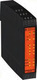
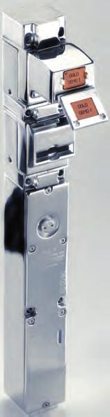
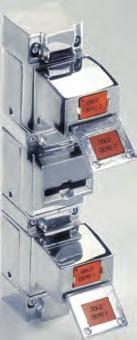
3 VARIMETER IMD Elecrical safey for power supplies An unplanned machine or sysem downime due o insulaion fauls can have serious consequences. Through early recogniion of such fauls in ungrounded neworks (IT neworks), DOLD insulaion moniors in he series VARIMETER IMD preven failures in elecric sysems and guaranee a higher level of operaional and sysem safey. LK 5896 RN 5897 RR 5886 VARIMETER EDS Faul localizaion during ongoing operaions In large indusrial faciliies, localizing insulaion fauls can be boh expensive and ime consuming. The VARIMETER EDS insulaion faul search sysem localizes insulaion fauls quickly and safely in complex, ungrounded AC/DC neworks. RR For informaion, call Swiches Unlimied Fax ech@swichesunlimied.com sales@swichesunlimied.com


4 Cusom-ailored measuring and monioring soluions. from DOLD Elecrical Safey Soluions DOLD offers a comprehensive selecion of measuring and monioring relays for your unique needs. The devices deec and provide early noificaion if criical limis of elecrical variables such as curren, volage, power, insulaion resisance, e ceera are violaed. This allows dangers o people and machinery o be reliably avoided. In addiion, he availabiliy of your machines and sysems will be increased and producion ouages will be minimized. DOLD s porfolio ranges from sandard devices for he monioring of individual variables o mulifuncional devices o flexible error message sysems. In grounded neworks, DOLD differenial curren moniors in he VARIMETER RCM series ensure reliable residual curren monioring. The differenial curren sensors can be used universally, as hey can deec boh direc and alernaing curren. RN 5883 ND 5015/070 VARIMETER RCM Signalling insead of shudown For informaion, call Swiches Unlimied Fax ech@swichesunlimied.com sales@swichesunlimied.com 13
5 Table of conens Funcion Page Funcion Page General Dold - Agens - Europe...5 sales@swichesunlimied.com - Worldwide...7 Phone: * Fax: Produc range DOLD - The Company...10 News...12 Table of conens...14 Alphabeical index...16 Produc selecions / Forewords - Insulaion moniors Measuring relays Faul annunciaors, SMS-Teleconrol modules...29 Accessories Dimensions General echnical definiions Furher available devices Funcion index General Condiions for he supply of producs and services Insulaion moniors - single and 3-phase AC-sysems, non-earhed...19 Insulaion monior for swiched off consumers, non-earhed...20 Insulaion monior for inplan generaor sysems for mixed sysems, non-earhed (AC / DC / 3 AC)...19 Insulaion monior for special applicaions...27 Insulaion monior Insulaion faul locaion sysem...20 Locaing curren injecor Insulaion faul locaor Residual curren ransformer for earhed sysems...20 Residual curren monior (RCM, Type A)...3 Residual curren monior, universal-curren-sensiiv (RCM, Type B)...9 Tes and indicaion panel Measuring relays Mulifuncional relays VARIMETER PRO...21 Mulifuncional relay Phase monior wih moor proecion Over and undervolage relay Volage monioring VARIMETER...22 Volage relays Overvolage relays Undervolage relays Baery symmery moniors Curren monioring VARIMETER...23 Curren relays Over- / undercurren relays Overcurren relays Undercurren relays Curren monior Curren-assymmery-relays Load monioring VARIMETER...24 Moor load moniors Underload moniors Reverse power monioring Mains monioring VARIMETER...25 Undervolage relays Phase indicaors Phase moniors Phase-sequence relays Asymmery relays Frequency relays Neural moniors...3 Fuse moniors Mains frequency moniors Measuring relays for special applicaions VARIMETER...27 Volage and frequency moniors for generaor ses on public grid Mains frequency monior for self-producion plan Undervolage relays f. med. areas acc. o DIN VDE * Over- / undervolage relays for self-producion plan Baery symmery moniors Valve monior Transformer proecion... * 14 For informaion, call Swiches Unlimied Fax ech@swichesunlimied.com sales@swichesunlimied.com

6 Table of conens Funcion Page Monioring physical values VARIMETER...28 Sand-sill moniors Speed moniors Level sensing relays Temperaure relays Thermisor moor proecion relays Valve Monior Accessories for measuring relais...28 Noise filer Faul annunciaors, SMS-Teleconrol module Faul annunciaors Faul annunciaor sysems... 4 Faul monioring sysem INFOMASTER B Sysem overview Common Alarm Annunciaors, bus connecion New- / firs- / common signal annunciaors, bus connecion Tex display uni, bus connecion GSM Module... * SMS Teleconrol module Accessories for faul annunciaors Lamp eser For Sales & Suppor, Conac Swiches Unlimied Phone: Fax:
7 Alphabeical index Type Funcion Page Type Funcion Page AA AA Speed monior AA Frequency relay AA Frequency relay AA Undervolage relay AC Accessories AD AD Faul annunciaor sysem AD Faul annunciaor sysem AD Faul annunciaor sysem AI AI Thermisor moor proecion relay AI 941N...Phase sequence relay AI Asymmery relay AK AK Asymmery relay BA BA Volage relay BA Volage relay BA Thermisor moor proecion relay BA Asymmery relay BA Phase sequence relay BA Asymmery relay BA Undervolage relay BA Curren relay BA Volage relay BA Speed monior BA 9054/331...Baery symmery monior BA 9054/332...Baery symmery monior BA Underload Monior (cos ϕ) BA Temperaure monioring relay BA Frequency relay BC BC 9190N...Volage drop deecor BD BD Sandsill monior BD Phase monior BH BH Moor load monior BH Moor load ransmier BH Reverse power monioring D Dimensions EH EH Display uni EH Display uni EH Display uni EH Display uni EH Tex display Uni EH Faul annunciaor sysem... 4 EP EP Faul annunciaor sysem EP Faul annunciaor sysem F Funcion Index Furher available devices G General condiions General echnical definiions IK IK Curren monior IK Volage monior IK Volage monior IK Speed monior IK Underload monior (cos ϕ) IK Valve monior IK Temperaure monioring relay IK Frequency relay IK Sandsill monior IK Phase indicaor IK Phase monior IK Overvolage relay, 3-phase IK Undervolage relay, 3-phase IK Overvolage relay, single phase IK Undervolage relay, single phase IK Phase sequence indicaor IK Phase sequence monior /-relay IK Overcurren relay IK Undercurren relay IK Overcurren relay IK Undercurren relay IL IL 5201/ Overcurren relay IL Insulaion monior IL Insulaion monior IL Residual curren monior... 3 IL Faul annunciaor sysem IL Faul annunciaor sysem IL Curren monior IL Speed monior IL Phase sequence module IL Neural monior... 3 IL Undervolage relay For informaion, call Swiches Unlimied Fax ech@swichesunlimied.com sales@swichesunlimied.com
8 Alphabeical index Type Funcion Page Type Funcion Page IL Fuse monior IL Over- and undervolage relay IL Undervolage relay o eec auo-reclosing IL Phase monior wih hermisor moor proecion IL Phase monior IL Temperaure monioring relay IL Sandsill monior IL Level sensing relay IL Thermisor moor proecion relay IL Undervolage relay, 3-phase IL Undervolage relay, 3-phase wih es key IL Overcurren relay IL Undercurren relay IL Over- and undercurren relay IL Frequency relay IN IN 5880/710...Insulaion monior IN 5880/7...Insulaion monior INFOMASTER B...Sysem overview IP IP Insulaion monior IP Residual curren monior Type A wih forcibly guided indicaor conacs...* IP 5880/7...Insulaion monior IP Fuse monior IP Over- and undervolage relay IP /107...Undervolage relay...* IP /107...Undervolage relay...* IP 90/107...Undervolage relay...* IP 91/107...Transformer proecion...* IP Overcurren relay IP Undercurren relay IP Over- and undercurren relay IP Curren asymmery relay wih inegraed curren ransformer up o 100 A IR IR Residual curren monior... 3 LG LG Noise Filer LK LK Insulaion monior LK Insulaion monior LK Insulaion monior MH MH Insulaion monior MH Speed monior MH 9055N/5_0...Speed monior...* MH Volage relay MH Mains rrequency monior MH Mulifuncion measuring relay MH Moor load monior MH 9837N...Frequency relay MH 9837/5_0...Frequency relay MK MK 5130N...Noise Filer MK 5880N...Insulaion monior MK 9003-ATEX...Thermisor moor proecion relay MK 9040N...Asymmery relay MK 9053N...Curren relay MK 9054N...Volage relay MK 9055N...Speed monior MK 9055N/5_0...Speed monior...* MK 9056N...Phase sequence relay MK 9064N...Volage relay MK Underload monior MK 9143N...Mains frequency monior MK 9151N...Level sensing relay MK 9163N...Thermisor moor proecion relay MK 9163N-ATEX..Thermisor moor proecion relay MK 9300N...Mulifuncion measuring relay MK 9397N...Moor load monior MK 9837N...Frequency relay MK 9837N/5_0...Frequency relay MK Lamp eser MK Lamp eser ND ND Residual curren ransformer ND Residual curren ransformer... 6 ND Residual curren ransformer... 0 ND Residual curren ransformer ND Residual curren ransformer... 7 OA OA Phase sequence module RK RK Phase monior RK Phase sequence monior /-relay RK Undervolage relay RK Phase monior RL RL Volage relay RL Curren relay RL Volage relay RL Fuse monior * Daa shee on reques For informaion, call Swiches Unlimied Fax ech@swichesunlimied.com sales@swichesunlimied.com 17
9 Alphabeical index Type Funcion Page Type Funcion Page RL Phase monior RN RN Residual curren monior, Type B for AC and DC Sysems... 9 RN 5897/010...Insulaion monior RN 5897/300...Insulaion monior RN Fuse monior RN Phase monior RP RP SMS-Teleconrol Module RP Insulaion monior RP Common Alarm Sysem, Bus Connecion RP Common Alarm Sysem, Bus Connecion RP New- / Firs- /Common Signal Annunciaor RP New- / Firs- /Common Signal Annunciaor RP Reverse power monioring RP Volage and frequency monior RP Volage- and frequency monior acc. o VDE-AR-N RP 98...Volage and frequency monior RR RR Locaing curren injecor RR Insulaion faul locaor SK SK Speed monior SK Underload monior (cos ϕ) SK Valve monior SK Temperaure monioring relay SK Frequency relay SK Sandsill monior SK Phase indicaor SK Phase monior SK Overvolage relay, 3-phase SK Undervolage relay, 3-phase SK Overvolage relay, single phase SK Undervolage relay, single phase SK Phase sequence indicaor SK Phase sequence monior /-relay SK Overcurren relay SK Undercurren relay SK Overcurren relay SK Undercurren relay SL Faul annunciaor sysem SL Faul annunciaor sysem SL Speed monior SL Phase sequence module SL Underload monior (cos ϕ) SL Neural monior... 3 SL Undervolage relay SL Fuse monior SL Over- and undervolage relay SL Undervolage relay o eec auo-reclosing SL Phase monior wih hermisor moor proecion SL Phase monior SL Temperaure monioring relay SL Sandsill monior SL Level sensing relay SL Thermisor moor proecion relay SL Undervolage relay, 3-phase SL Overcurren relay SL 9270CT...Overcurren relay SL Undercurren relay SL 9271CT...Undercurren relay SL Over- and undercurren relay SL 9277CT...Over- and undercurren relay SL Frequency relay SP SP Insulaion monior SP Fuse monior SP Over- and undervolage relay SP Overcurren relay SP 9270CT...Overcurren relay SP Undercurren relay SP 9271CT...Undercurren relay SP Over- and undercurren relay SP 9277CT...Over- and undercurren relay SP 9278CT...Curren asymmery relay wih inegraed curren ransformer up o 100 A UG UG Fuse monior UH UH Insulaion monior SL SL 5201/20007CT..Overcurren relay SL Insulaion monior SL Insulaion monior SL Residual curren monior For informaion, call Swiches Unlimied Fax ech@swichesunlimied.com sales@swichesunlimied.com
10 Monioring devices Produc selecion Insulaion moniors for non-earhed sysems VARIMETER IMD Funcion Sysem ype Nominal Volage [V] Response value Wih auxiliary volage Connecion for indicaor Housing syle Widh [mm] Type Page Insulaion monior Insulaion monior Insulaion monior Insulaion monior Insulaion monior Insulaion monior Insulaion monior Insulaion monior Insulaion monior Insulaion monior for rooms used for medical purposes mixed sysems mixed sysems mixed sysems mixed sysems mixed sysems mixed sysems AC; hree-phase AC; hree-phase AC; hree-phase AC; hree-phase AC: 400 DC: Insulaion monior DC 280 adjusable, 1 k... 2 M adjusable, 10 k... 1 M adjusable, 1 k... 2 M adjusable, 1 k... 2 M adjusable, 1 k... 2 M fixed, 10 k k adjusable, 5 k k adjusable, 5 k k adjusable, 5 k... 5 M adjusable, 50 k k adjusable, 5 k k + Disribuion board 52.5 RN 5897/ Disribuion board 52.5 RN 5897/ Swich cabine 90 LK Swich cabine 90 LK Swich cabine 90 LK Swich cabine 45 UH Disribuion board 35; 70 + Swich cabine 22,5; 45 IL 5880, IP 5880, SL 5880, SP 5880 MK 5880N, MH Disribuion board 70 RP Disribuion board 52,5; 70 Disribuion board Swich cabine IN 5880/710, IN 5880/7, IP 5880/7 IL 5881, SL Following produc are also available: AI 897, AI 898, EH 5878 The daa shees are available a For informaion, call Swiches Unlimied Fax ech@swichesunlimied.com sales@swichesunlimied.com 19
11 Monioring devices Produc selecion Equipmen for insulaion faul locaion VARIMETER EDS Funcion Nominal volage IT sysems Manual rese Bus inerface Operaing mode Operaing volage Widh [mm] Type Page Locaing curren injecor DC, AC, 3 AC V - RS-485 Maser / Slave AC / DC V 105 RR Isolulaion faul locaor DC, AC, 3 AC V selecale by conrol erminal RS-485 Slave AC / DC V 105 RR Residual curren ransformer Residual curren ransformer Residual curren ransformer Residual curren ransformer Residual curren ransformer ND ND ND ND ND Residual curren moniors for earhed sysems VARIMETER RCM Funcion Residual curren monior, Type A Residual curren monior, Type A, wih forcibly guided indicaor conacs Residual curren monior, Type A, wih inegraed ransformer Residual curren monior, Type B AC; DC pulsaing AC; DC; pulsaing AC; DC; pulsaing Type of volage AC; DC; DC pulsaing ; Disribuion board Swich cabine IL 5882, SL Disribuion board 52.5 IP * ; Adjusable measuring ranges [A] Relay conacs / oupu Tes buon Adjusable operae delay Rese buon Broken conducor deecion Housing syle Disribuion board 105 IR Disribuion board 52.5 RN Widh [mm] Type Page 3 * Daa shee can be ordered 20 For informaion, call Swiches Unlimied Fax ech@swichesunlimied.com sales@swichesunlimied.com
12 Monioring devices Produc selecion Mulifuncional relays VARIMETER PRO Funcion 1-/3-phase Sandard measuring range Measuring range max. Conacs Adjusable operae delay Auxiliary volage required Housing Syle Widh [mm] Type Page Mulifuncional measuring relay Phase monior wih deecion of under-/overvolages, unbalance, phase failure, phase sequence Phase monior wih hermal moor proecion, deecion of under-/overvolages, unbalance, phase failure, phase sequence Phase monior wih deecion of under-/overvolages, unbalance, phase failure, phase sequence Traformer proecion: Curren and emperaure monioring Over-/undervolage relay, opionally wih unbalance and phase-sequence deecion 1; AC V 3 AC 400 V V 1 C/O; 2 x 1 C/O + + Swich cabine 22,5; 45 MK 9300N, MH V 2 C/O + + Swich cabine 45 BD /N AC 400/230 V 400 V 2 C/O Disribuion board Swich cabine 3/N AC 400/230 V 400 V 1 C/O; 2 C/O A; >3,8 k 3 AC 400 V 480 V Disribuion board Swich cabine IL 9086, SL IL 9087, SL A 2 x 2 C/O + Disribuion board 70 IP 91/107 * 2 C/O; 4 C/O + Disribuion board Swich cabine 35; 70 35; 70 IL 9077, IP 9077, SL 9077, SP C/O = changeover conac * Daa shee can be ordered For informaion, call Swiches Unlimied Fax ech@swichesunlimied.com sales@swichesunlimied.com 21
13 Monioring devices Produc selecion Volage monioring VARIMETER Funcion 1-/3-phase Max. measuring range Conacs Operae delay Auxiliary volage required Housing syle Widh [mm] Type Page Volage relay 1 DC 250 V 1 C/O + Swich cabine 35 RL Volage relay 1 AC 300 V 1 C/O + Swich cabine 35 RL Volage relay, digial 1 AC/DC 300 V 1 C/O + + Swich cabine 22.5 MK 9064N 160 Volage relay, digial 1 AC/DC 600 V 2 x 1 C/O + + Swich cabine 45 MH Volage relay 1 AC/DC 1000 V 2 C/O + + Swich cabine 45 BA 9054, MK 9054N 166 Volage relay 1 AC 660 V 1 C/O; 2 C/O + Swich cabine 45 BA Volage relay 1 AC 690 V 2 C/O + Swich cabine 45 BA Volage relay undervolage, overvolage, residual ripple 1 DC 24 V 1 C/O; 2 C/O + Disribuion board 17.5 IK 9044, IK Overvolage relay 3 AC 440 V Overvolage relay 1 AC 230 V Over- and undervolage relay 3 AC 480 V 1 C/O; 2 C/O 1 C/O; 2 C/O 2 C/O; 4 C/O Undervolage relay 3 AC 690 V 2 C/O + Undervolage relay, deecion of shor-ime phase failures 1 AC 230 V Undervolage relay 3 AC 500 V 1 C/O; 2 C/O 1 C/O; 2 C/O Undervolage relay 1 AC 400 V 1 C/O + Undervolage relay 3 AC 440 V 2 C/O + Undervolage relay 3 AC 400 V Undervolage relay o deec auo-reclosing Undervolage relay for rooms used for medical purposes Undervolage relay for rooms used for medical purposes Undervolage relay for rooms used for medical purposes 1 C/O; 2 C/O 3 AC 500 V 2 C/O + NO = normally open conac, NC = normally closed conac, C/O = changeover conac Following produc are also avaible: IL 9070 ; The daa shee are available a * Daa shee can be ordered Disribuion board Swich cabine Disribuion board Swich cabine Disribuion board Swich cabine Swich cabine for fron panel mouning ; 70 35; 70 IK 9170, SK IK 9172, SK IL 9077, IP 9077, SL 9077, SP BA 9043, AA Swich cabine 22.5 BC 9190N Disribuion board Swich cabine Disribuion board Swich cabine Disribuion board Swich cabine IK 9171, IL 9171, SK 9171, SL IK 9173, SK IL 9071, SL Disribuion board 17.5 RK Disribuion board Swich cabine IL 9079, SL AC 230 V 2 C/O + Disribuion board 70 IP /107 * 3 AC 400 V 1 AC 230 V 1 NO, 2 NC 2 NO, 2 NC + Disribuion board 70 IP 90/107 * + Disribuion board 70 IP /107 Baery symmery monior 1 0, ,2 V DC 2 C/O + + Swich cabine 45 BA 9054/331 BA 9054/332 *
14 Monioring devices Produc selecion Curren monioring VARIMETER Funcion 1-/3-phase Max. measuring range Conacs Operae delay Auxiliary volage required Housing syle Widh [mm] Type Page RL AC 230 V 1 C/O + + Swich cabine 35 RL Curren relay 1 10 A 2 C/O + + Swich cabine 22.5 MK 9053N 206 Curren relay 1 25 A 1 C/O / 2 C/O Over-/undercurren relay 1 15 A 2 C/O Swich cabine 45 BA Disribuion board Swich cabine IL 9277, SL Over-/undercurren relay A 2 C/O + + Swich cabine 35 SL 9277CT 214 Over-/undercurren relay 3 15 A Over-/undercurren relay A 2 x 2 C/O 2 x 2 C/O + + Overcurren relay 1 15 A 1 C/O + + Overcurren relay 1 50 A 1 C/O / 2 C/O Disribuion board Swich cabine IP 9277, SP Swich cabine 70 SP 9277CT Overcurren relay 3 15 A 2 C/O + + Disribuion board Swich cabine Disribuion board Swich cabine Disribuion board Swich cabine IK 9270, SK IL 9270, SL IP 9270, SP Overcurren relay A 2 C/O + + Swich cabine 35;70 SL 9270CT, SP 9270CT 220 Overcurren relay 1 10 A 2 C/O + + Disribuion board Swich cabine IK 9272, SK Overcurren relay 1 5 A 1 C/O + + Disribuion board 35 IL 5201/ Overcurren relay 1 50 A Undercurren relay 1 15 A 2 x 1 C/O 2 x 1 C/O + + Swich cabine 35 SL 5201/20007CT Undercurren relay 3 50 A 1 C/O + + Undercurren relay A 1 C/O / 2 C/O + + Disribuion board Swich cabine Disribuion board Swich cabine Disribuion board Swich cabine IK 9271, SK IL 9271, SL IP 9271, SP Undercurren relay 1 15 A 2 C/O + + Swich cabine 35 SL 9271CT 231 Undercurren relay A 2 C/O + + Swich cabine 70 SP 9271CT 231 Undercurren relay A 2 C/O + + Disribuion board Swich cabine IK 9273, SK Curren monior 1 10 A 1 C/O + Disribuion board 17.5; 35 IK 8839, IL Curren-assymmery-relay 3 15 A 1 INV; 1 NO + + Disribuion board Swich cabine IP 9278, SP Curren-assymmery-relay A 2 C/O + + Swich cabine 70 SP 9278CT 242 NO = normally open conac, C/O = change-over conac; / = opional Following produc are also available: ML 9701 ; The daa shee are available a 23
15 Monioring devices Produc selecion Load monioring VARIMETER Funcion 1-/3-phase Measuring range, max. Oupu conacs max. Operae delay Auxiliary volage required Housing syle Widh [mm] Type Page Moor load monior 3 Moor load monior 3 Moor load monior 1; 3 Moor load ransmier 1; 3 Underlaod monior (cos ϕ monior) Underlaod monior (cos ϕ monior) Underlaod monior (cos ϕ monior) Underlaod monior (cos ϕ monior) 12 A (8 kw) 12 A (8 kw) 40 A (37 kw) 40 A (37 kw) 1; 3 10 A 1; 3 10 A 1 C/O + + Swich cabine 22.5 MK 9397N x 1 C/O + + Swich cabine 45 MH x 1 C/O V/ ma 1 C/O / 1 C/O, 1 NO 1 C/O + 1 C/O, 1 NO 1; 3 8 A 1 C/O + + Swich cabine 45 BH Swich cabine 45 BH Swich cabine 45 BA Swich cabine 22.5 MK Swich cabine Disribuion board IK 9065, SK ; A 1 C/O + Swich cabine 45 SL 9065CT 268 Reverse power monioring 1; 3 40 A 2 C/O + + Swich cabine 45 BH Reverse power monioring 1; 3 5 A 2 C/O + + Disribuion board 70 RP NO = normally open conac, C/O = change-over conac Following produc are also available : BA 9067 ; The daa shee are available a 24
16 Monioring devices Produc selecion Mains monioring VARIMETER Funcion 1-/3-phase Sandard measuring range * Max. measuring range Conacs Operae delay Auxiliary volage required Undervolage relay 3/N AC 3 wih es key 400/230 V 400 V 2 C/O Disribuion board 35 IL Phase monior wih deecion of 3/N AC under-/overvolages, unbalance, V 1 C/O; Disribuion board 35 IL 9087, 400/230 V 2 C/O Swich cabine 35 SL 9087 phase failure, phase sequence 147 Phase monior wih deecion of under-/overvolages, unbalance, 3 3AC 400 V 690 V 2 C/O + + Swich cabine 45 BD phase failure, phase sequence Phase monior wih hermal moor proecion, deecion of 3/N AC Disribuion board 35 IL 9086, V 2 C/O under-/overvolages, unbalance, 400/230 V Swich cabine 35 SL phase failure, phase sequence Phase indicaor 3 3/N AC Disribuion board 17.5 IK 9168, 400 V 400; 230 V Swich cabine 17.5 SK AC Phase monior V/ 230 V 1 C/O + Swich cabine 35 RL V Phase monior 3 3 AC V/ 525 V 1 C/O + Swich cabine 52.5 RN V Phase monior 3 3/N AC 400; 230 V 400 V 1 C/O Disribuion board 17.5 RK Phase monior 3 IK 9169, 3/N AC 400; 230 V 400 V 1 C/O Disribuion board 17.5 RK 9169, Swich cabine 17.5 SK Phase sequence relay 3 AC Insallaionsvereiler 35 IL 9059, 690 V 1 C/O 690 V Schalschrank 35 SL Phase sequence relay 3 AC V 690 V 1 NC Moor erminal box 62 OA Phase sequence relay 3 3 AC 400 V 550 V 1 C/O; BA 9041, Swich cabine 45 2 C/O AI 941N 289 Phase sequence relay 3 3 AC V 500 V 2 C/O Swich cabine 22.5 MK 9056N 291 Phase sequence indicaor 3 3 AC 400 V 3 AC Disribuion board 17.5 IK 9178, 400 V Swich cabine 17.5 SK IK 9179, Phase sequence monior (Phase 3 AC 3 3 AC 400 V sequence relay) 400 V 1 C/O Disribuion board 17.5 RK 9179 Swich cabine 17.5 SK Asymmery relay 3 3 AC 400 V 3 AC 690 V 2 C/O + Swich cabine 75 AK Asymmery relay 3 3 AC 400 V 3 AC BA 9040, 2 C/O + Swich cabine 22.5; V MK 9040N 299 Asymmery relay 3 3AC 400 V 3 AC 400 V 2 C/O Swich cabine 45 BA 9042, AI Frequency relay Hz 600 Hz 1 C/O; BA 9837, 2 C/O + + Swich cabine 45 AA 9837, AA Frequency relay Hz 300 Hz 1 C/O; Disribuion board 35 IL 9837, C/O Swich cabine 35 SL Neural monior 3 Housing syle 3/N AC 400; 230 V 415 V 2 C/O + Disribuion board Swich cabine Widh [mm] Type IL 9069, SL 9069 Page 3 NC = normally closed conac, C/O = change-over conac * Oher measuring ranges on reques 25
17 Monioring devices Produc selecion Mains monioring VARIMETER Funcion Fuse monior 1; 3 Fuse monior 1; 3 Fuse monior 3 1-/3-phase 3 AC 0/64 V 3 AC 400/230 V 3 AC 230/130 V Sandard measuring range * 3 AC 0 V 3 AC 400 V Max. measuring range Conacs Operae delay Auxiliary volage required Housing syle Widh [mm] 1 C/O + Swich cabine 35 RL C/O + Swich cabine 52.5 RN AC V 690 V 2 C/O Disribuion board Swich cabine Type IL 9075, IP 9075, SL 9075, SP AC 3 AC Fuse monior 3 2 C/O + Swich cabine 22.5 UG V 400V 50/60 Disribuion board 17.5 IK 9143, Frequency relay 1 50; 60 Hz 1 C/O Hz Swich cabine 17.5 SK 9143 MK 9837N, Frequency relay 1 1, Hz 600 Hz 2 C/O + Swich cabine 22.5; MH 9837 MK 9837N/ 5_0, Frequency relay 1 1, Hz 600 V 2 C/O + + Swich cabine 22.5; MH 9837/ 5_0 50/60 2 C/O; MK 9143N, Mains frequency relay 1 50; 60 Hz + + Swich cabine 22.5; Hz 4 C/O MH 9143 Page 316 NC = normally closed conac, C/O = change-over conac * Oher measuring ranges on reques 26
18 Monioring devices Produc selecion Measuring relays for special applicaions VARIMETER Funcion 1-/3-phase Sandard measuring range Conacs Adjusable operae delay Auxliary volage required Housing syle Widh [mm] Type Page Volage and frequency monior for generaor ses on public grid Volage and frequency monior for generaor ses on public grid acc. o VDE-AR-N 4105 Volage and frequency monior for generaor ses on public grid inernaional Mains frequency monior for self-producion plan Undervolage relay, f. med.areas acc. o DIN VDE Undervolage relay, f. med.areas acc. o DIN VDE Undervolage relay, f. med.areas acc. o DIN VDE Over- and undervolage relay as opion wih unbalance- and phase sequence deecion for selfproducion plan Baery symmery monior 1 Valve monior: curren and broken conducor monioring Transformer proecion: Curren and emperarure monioring f. med.areas acc. o DIN VDE Hz; AC 230 V 50 Hz; AC 400 / 230 V AC 400 / 230 V 1 50 / 60 Hz 3 AC 230 V 3 AC 400 V 3 AC 400 V 2 C/O + Disribuion board 70 RP C/O + Disribuion board 70 RP NO + + Disribuion board 70 RP C/O; 4 C/O 2 NO + 2 NC 2 NO + 2 NC 1 NO + 2 NC + + Swich cabine 22.5; 45 MK 9143N, MH Disribuion board 70 IP /107 * + Disribuion board 70 IP /107 * + Disribuion board 70 IP 90/107 * kω 2 C/O + Disribuion board 52.5; 70 0, ,2 V DC 1 < 0,7A 1 C/O A; > 3.8 kω 2 C/O + + Swich cabine 45 Disribuion board Swich cabine NO = normally open conac, NC = normally closed conac, C/O = change-over conac Following produc are also available: AI 940 ; The daa shee are available a * Daa shee can be ordered IN 5880/710, IN 5880/7 BA 9054/331, BA9054/332 IK 9076, SK x 2 C/O + Disribuion board 70 IP 91/107 *
19 Monioring devices Produc selecion Monioring physical values VARIMETER Funcion Measuring range, max. Conacs Operae delay Housing syle Widh [mm] Type Page Sand-sill monior 2 NO, 2 NC Swich cabine 45 BD Sand-sill monior IPM 1 C/O + Disribuion board 17.5; 35 Speed monior IPM 1 C/O + Swich cabine 45 Speed monior IPM 1 C/O + Disribuion board Swich cabine 17.5; ; 35 Speed monior IPM 2 C/O Disribuion board 22.5; 45 Speed monior IPM 2 C/O Disribuion board 22.5; 45 Level sensing relay 450 kω Temperaure relay 600 C 2 x 1 C/O 1 C/O, 1 NO Temperaure relay 300 C 1 C/O Thermisor moor proecion relay Thermisor moor proecion relay Thermisor moor proecion relay Thermisor moor proecion relay Transformer proecion: Curren and emperaure monioring Valve monior: curren and broken conducor monioring + Disribuion board Swich cabine ; 45 IK 9144, IL 9144 SK 9144; SL 9144 BA 9055, AA 9050 IK 9055, IL 9055, SK 9055, SL 9055 MK 9055N, MH 9055 MK 9055N/5_0, MH 9055/5_0 IL 9151, SL 9151, MK 9151N * 387 Swich cabine 35 BA Disribuion board Swich cabine 17.5; ; 35 > 3.8 kω 2 C/O Swich cabine 45 > 3.8 kω 2 C/O Disribuion board Swich cabine > 3.8 kω 2 C/O Swich cabine 22.5 IK 9094, IL 9094, SK 9094, SL 9094 BA 9038, AI 938 IL 9163, SL 9163 MK 9163N, MK 9163N-ATEX > 3.1 kω 2 C/O Swich cabine 22.5 MK 9003-ATEX A; > 3.8 kω 2 x 2 C/O < 0.7A 1 C/O NO = normally open conac, C/O = change-over conac * Daa shee can be ordered Disribuion board 70 IP 91/107 * Disribuion board Swich cabine IK 9076, SK Accessories for measuring relays Nominal volage U N max. Funcion 3-phase wihou PE connecoin wih PE connecoin Housing syle Widh [mm] Deph [mm] Type Page Noise filer + 3 AC 1000 V 3/N AC 860 / 500 V Swich cabine MK 5130N, LG
20 Monioring devices Produc selecion Faul annunciaor sysems INFOMASTER, accessories Funcion Faul annunciaor sysem Faul annunciaor sysem Faul annunciaor sysem Common alarm annunciaor New- / Firs- / Common signal annunciaor Indicaions panel for faul annunciaor sysem Indicaions panel for new-value and firs-up annunciaor Tex display uni for New-value and firs-up annunciaor sysem Faul annunciaor sysem Faul annunciaor sysem GSM-Module busconnecion SMS-Teleconrol module 6 8 R LED 12 A ; 6 Alarm inpus Alarm inpus, exendable up o Oupu for horn Oupu for horn 1; 3; 10 NO A / R LED Oupu for horn NO NO Operae delay A / R A / R LED LED LED LED LED 1; 3; 10 NO A / R LED Oupu for horn 303 A Oupu for signal lamp LED Visual indicaion Operaing principle: Energizedon rip (A)/ de-energized-on-rip (R) de repos (R ) Acousic indicaion Oupu for horn Special feaures configurable; buscompaible configurable; buscompaible configurable; buscompaible configurable; buscompaible configurable; buscompaible configurable; buscompaible Housing syle Fron panel mouning 96 x 96 EH Swich cabine 45 AD Disribuion board Swich cabine Disribuion board Swich cabine Disribuion board Swich cabine Fron panel mouning 96 x 96 Fron panel mouning 96 x 96 IL 5990, IL 5991, SL 5990, SL 5991 RP 5990, RP 5991 RP 5994, RP 5995 EH 5990, EH 5991 EH 5994, EH Fron panel mouning 96 x 96 EH Fron panel mouning 72; 144 Swich cabine 45 Widh [mm] EP 5966, EP 5967 AD 5998, AD Disribuion board 70 RP 5810 * LED Disribuion board 70 RP Type Page Accessories for faul annunciaors: Lamp eser LED Disribuion board Swich cabine MK 9994, MK NO = normally open conac Following produc are also available : AI 990, AI 991, AI 992, AI 998, UP
21 Monioring hardware DOLD s monioring relays such as insulaion moniors, differenial-curren moniors and measuring relays reliably monior elecrical quaniies such as curren, volage, power, resisance, ec. and annunciae faul condiions and disurbances. Thus, hese producs proec also complex sysems and ensure an opimal producion flow. LEDs on he fron provide visual saus indicaions. Oupu conacs or inerfaces for bus sysems allow a furher ransmission of informaion from hese devices, e.g. o faul annunciaors. Monioring elecrical quaniies : Sysem Phase Volage Phase failure / Asymmerie Broken neural wire Frequency Insulaion failures Undervolage and overvolage relays, volage moniors, single- and rhee-phase Phase-sequence relays, phase moniors, phase indicaors Unbalance relays Neural moniors Frequency relays Insulaion / differenial-curren moniors Monioring elecrical quaniies: Load Load Curren cos ϕ Effecive power Curren relays Underpower moniors Load moniors, overload moniors, load ransformers Monioring physical quaniies : Processes Insallaions Speed Temperaure Level Speed / zero-speed relays Tempeaure relays, hermisor moor proecion relays Neural monior Level sensing relays Monioring of muliple quaniies / special applicaions Mulifuncional relays Measuring relays for specific applicaions 30
22 Insulaion monior Non-earhed (IT) sysems Insulaion monior Insulaion moniors are used in non-earhed sysems (IT sysems). They measure he insulaion resisance agains earh of he sysem o be moniored. Such sysems are proeced by insulaion moniors he use of hem in IT sysems is required by law by he norm Safey of Machinery DIN EN or DIN VDE Thanks o he deliberaely kep simple funcionaliy of insulaion moniors from DOLD cusomers benefi from a considerable cos advanage combined wih he high qualiy sandard accusomed from DOLD. Insulaion moniors are used o avoid accidens and downimes in he case of insulaion failures and o proec agains fire and accidens. For insulaion monioring in earhed sysems, differenial-curren moniors are used. Earhed (TN) sysems Differenial-curren moniors Differenial-curren moniors are used in earhed sysems (TN sysems). They monior he faul curren on he basis of he differenial-curren measure men and are mainly used o preven expensive downimes and fire risk ha is laenly presen due o evolving insulaion fauls. They guaran ee an increased safey of operaing and insallaions. For insulaion monioring in non-earhed sysems, insulaion moniors are used. Problem: The sandards DIN VDE and DIN EN require he use of an insulaion monior in non-earhed sysems. Our objecive is o mee his sandard as cos-effecive as possible. Ensure proecion agains fire and accidens by early deecion of earh faul currens and slowly evolving insulaion fauls, e.g. safeguarding fire/explosion-prone areas Preven unscheduled downimes due o earh fauls in medical areas. Problem: Avoid he risk of fire and accidens due o slowly evolving insulaion fauls: High-resisance fauls o exposed conducive pars and o earh are presen if he conducive connecion of he faul locaion includes resisances. There is jus a risk of fire when he power loss on he faul locaion is 60 W. This corresponds o a faul curren of 260 ma a 230 VAC. Overcurren devices would no operae in his case. Avoid cosly downimes, ge an informaion lead o ensure high operaional reliabiliy beween mainenance inervals L L I 1 IM RF I F RF N N I 2 PE CE CE IMD M10131_a PE I F =I 1 -I 2 RCM M10132_a R F : Faul resisance I F : Faul curren C E : Earh capaciance IW : Insulaion monior R F : Faul resisance (insulaion faul) I F : Faul curren DW : Differenial-curren monior W : Energy consumpion on he faul locaion Soluion: DOLD insulaion moniors are available for d.c. and hree-phase sysems, a.c. sysems and mixed sysems. Furher, our insulaion moniors can be used o monior swiched off loads, mobile power supply unis, d.c. sysems and rooms used for medical applicaions. Soluion: In heir sandard varian, DOLD differenial-curren moniors can be used for d.c. sysems or pulsaing d.c. sysems, and a universal-curren-sensiive varian is available for mixed sysems. 31
23 Measuring relays Basics of monioring echnology in low volage sysems Wha means asymmery (unbalance) in hree-phase sysems? The mos common sysem is he 400 V hree-phase sysem (fig. 1) formed from hree alernaing volages ha are displaced in ime by 120 el. (fig. 2). Beween he phases, L2, and L3, here are 3 phase-o-phase volages U -L2, U L2-L3, U L3- ha are also referred o as line-o-line volages. Graphically represened in a phasor diagram, hese volages resul in an isosceles riangle (fig. 3). This ype of represenaion is common in elecrical engineering o easily illusrae sinusoidal alernaing quaniies. The 3 volages agains he neural N of he ransformer are he sar volages (phase-o-neural volages) U -N, U L2-N, U L3-N which can also be drawn in he isosceles riangle. Under normal condiions in a hree-phase sysem, all volages are equal in heir magniude and all angles are 120 el. An deviaion from his is called asymmery (unbalance). How his affecs conneced loads is described below. o-phase volages agains he sar poin (neural conducor N) mus be mea sured and compared o each oher. Even he smalles volage dif ferences cause an asymmery. I can be calculaed by Asymmery (Unbalance) = ( -1 ) * 100 in (%) Eq.(1) In he second case i is enough o compare he magniude of he phaseo-phase volages and o deermine he asymmery (unbalance) wih equaion (1). Consequences of asymmery (unbalance) in hree-phase sysems 1. Neural conducor inerrupion Highes volage Lowes volage There are wo ypes of asymmery: Case 1: Given a siff sysem, i.e. he phase-o-phase volages are consan, he phase-o-neural volages on he load (measuring poin A) can change wihou changing he ouer symmery (fig. 4). This is he case wih asymmeric loads in sar connecions and inerruped neural conducor, i.e. wih open neural (sar) poin. U U -L2 U L2-L3 U L3- Case 2: However, if he phase-o-phase volages change, his will always cause a change of he phase-o-neural volages oo. This occurs wih moive-power loads when one phase fails (fig. 1b). The moor windings U and V induce a volage in he disconneced winding W, which does no longer correspond o he original sysem volage. Therefore, he hreephase sysem downsream of he fuses on he measuring poin B now became asymmeric. This is referred o as reverse power. To deec an asymmery in a sysem, for he 1s case, he 3 phase- 120 el 120 el 120 el M8064 Fig. 2: Sinusoidal ime characerisic 120 el MP mains-ransformer secondary par L2 UL2-L3 UL3-MP UL3-120 el measuring poin ~ inerrupion L3 N L3 UL2-MP U-MP U -L2 M8065_a Fig. 3: Phasor diagram inerrupion ~ A B L3 X Y Z U V W N N M6026 L2 M8066_a L2 M8067 Fig. 1a: Ohmic load Fig. 1b: Moive-power load Fig. 4: Asymmerical sar volages Fig. 5: Asymmerical phase-o-phase volages 32
24 Measuring relays A firs, he case of a broken neural conducor is considered. As shown in fig. 4, he phase-o-neural volages can reach dangerously high values, up o he magniude of he phase-o-phase volage in exreme cases. I is clear ha his would damage or desroy conneced loads. Such overvolages are a consequence of a severe unbalance as is encounered frequenly in privae or commercial sysems. This is due o he fac ha he elecrical devices used here are mainly single-phase consumers wih differen power consumpions. Alhough aenion is paid in building insallaions o symmerically dis ri bue loads o all 3 phases unsymmerical loading canno be avoided in he daily use of elecric equipmen. An example for a highly unsymmerical loading may be a washing machine (2000 W) on phase, bulbs (100 W) on phase L2 and a radio (20W) on phase L3 (fig. 6b). In normal sysem operaion, he correc sysem volage (230 V) is applied o all loads. However, if he neural conducor is inadverenly no recon nec ed afer work on he insallaion, for example, and he sysem is recon nec ed, he volage on small loads can reach very high values. In our example, he radio would be a a high risk (power pack would be damaged) and he bulbs would burn ou. I should be he objecive o signal even he smalles unbalances by means of measuring relays and o disconnec loads if required before dangerous condiions can evolve. Convenional over/undervolage relays are no suied for an early deecion. To deec an asymmery of 5 %, for example, according o equaion (1) only by he use of volage relays hey had o be se o a value of 2.5 % overvolage or undervolage. However, his would be no useful as here is no need o disconnec a an undervolage of only 2.5 %. Therefore, DOLD s neural monior IL 9069 would be a suied measuring device for his case because i deecs an asymmery of he phase-o-neural volages. As he phase-o-neural volages can reach high values in case of a faul, as menioned above, he measuring relay mus be raed for his o preven i from being damaged. Figure 6a shows an example how he neural monior IL 9069 can proec an insallaion agains overvolage. 2. Reverse volage Reverse volage, ofen also called reverse feeding, becomes an issue whenever a conducor is inerruped in he elecrical insallaion. Such an inerrupion can be caused by a blown fuse, a broken conducor or a conac failure in a swiching device, for example (Fig. 1b). However, a reverse volage only occurs when a hree-phase moor or ransformer is presen. Because moors running on wo phases due o an inerrupion have he characerisic o regenerae he missing sysem phase by hemselves. However, magniude and angle of his volage do no mach wih he original sysem volage. Therefore, he hree-phase sysem became asymmerical downsream of he inerrupion poin (measuring B, Fig. 1b). The exen of asymmery depends on he ype, size and loading of he moor. In he pas, he above behaviour was deliberaely used o generae a hree-phase sysem from an exising single-phase sysem. Today, in he age of power elecronics, his is no longer necessary. In our case, i would be even derimenal when a phase fails in sysems wih elecrical drives. The problem is ha a single-phase operaion canno be immediaely deeced because he drives coninue o operae wihou changes for he momen. Only when he operaing condiion is deliberaely changed i would be deeced, bu hen i may be oo lae. Three-phase moors canno sar on a single-phase sysem, for example. Also a reversal of he roaional direcion by plugging is no longer possible because he moor would coninue o run in is original direcion even afer plugging. This may be dangerous if a reversal is needed for safey reasons such as wih presses and calenders. Also moors for elevaors and cranes would sar in he opposie direcion due o he pulling load. Again, asymmery (unbalance) relays can be used o preven condiions of his ype. Bu in his case, devices are needed ha compare he hree phase-o-phase volages and evaluae hem according o equaion 1. As described for he neural conducor, smalles amouns of asymmery are deeced, which canno be deeced by normal volage relays. Figure 7 represens he correc connecion of a moor feeder, as an example. The undervolage relay wih inegraed unbalance deecion IL 9071/0 is used here. Please noe ha he secion beween asymmery relay and moor is no moniored. If his is required for safey reasons, he undercurren relay IP 9271 mus be addiionally looped in he moor feeder. Wih his measure, he whole drive is hen opimally proeced agains phase failure and broken conducor. Noe: For he deecion of asymmery, also he BA 9040 would be suiable, and he broken conducor relay AI 940 for undercurren deecion. However, devices from he I range have been seleced for reasons of uniformiy. L2 F1 F2 K1 L2 L3 PE L3 F3 N PE L2 Tes Prüf-and und service Serviceschaler swich L3 F4 F5 F6 I> I> I> L2 L3 IL9069 A1 L2 L3 IL9071/0 N 14 K1 ~ IP9172 A2 U V W M8068 M 3~ M8069 Figure 6a Neural monior Fig. 7: Monioring for broken conducor and unbalance 33
25 Measuring relays Monioring of elecrical sysems for undervolage and overvolage 1. Funcion principle of volage measuring relays The consideraions below are no only resriced o volage monioring bu also apply correspondingly o he monioring of curren, cos ϕ, power, emperaure, frequency, ec. Once we have discussed above a special case of under/overvolage, namely asymmery (unbalance), we now deal wih he normal case, i.e. he monioring of elecrical sysems for under/overvolage. In syems where reverse feeding is no o be expeced a sandard volage measuring relay is sufficien for monioring. All DOLD measuring relays and in paricular he volage measuring relays work on he basis of he same principle, no maer wheher hey operae wih or wihou auxiliary volage U H. In he following, he funcion principle is described in more deail on he example of an undervolage relay. Wih he use of an undervolage relay, he user wans o deec a downward deviaion from he nominal volage, which underruns he permissible olerance, e.g. 20 %. Given a 230 V AC sysem, his is an undervolage of 184 V. The device has wo swiching poins, an upper and a lower. To preven confusing we speak of upper and lower swiching poins below. In a hree-phase measuring relay, he upper swiching poin mus a firs exceeded in all hree phases a he same ime in order o enable he device wih he undervolage feaure o go o he good sae. Tha means in our example ha he upper swiching poin mus be se o approx. 228 V o allow he device o pick up a a sysem volage of 230 V. If hen he volage drops o a value jus under 228 V, he device will no respond o i for he momen. Only when he lower swiching poin is underrun he relay repors a faul. For his, i is enough ha only one of he hree volages drops under he lower swiching poin. Measuring relays may have wo differen response principles when he measured value has over/underrun a swiching poin. In he open-circui principle, he signal relay in he oupu only picks up when he faul, e.g. overvolage occurs. Wih he closed-circui principle, he oupu relay is permanenly picked up (energized) in he good range of he measured quaniy and will only drop ou in case of a faul. To preven shor-ime volage dips from causing an undesired alarm he oupu relay can be operaed wih a ime delay. If he sysem volage reaches again is original value wihin he delay ime 1 he oupu relay will no operae. Likewise, a ime delay 1 can be realized when he measured volage reurns o he good range (refer o Fig. 8). Due o he measuremen principle used, namely he arihmeic averaging, a sysem-specific delay ime 0 resuls in he measuring inpu. A each variaion of he measured volage, small capaciances in he device are caused o charge and discharge. Depending on he amoun of he vol age jump, i akes beween 100 ms and 1 s before he new measuremen inernally unes in. Now, he five mos imporan parameers are known ha can be se ogeher or individually on a volage measuring relay by he user or are fixed se in he facory These parameers include: Upper swiching poin, lower swiching poin, response principle, delay ime 1, and delay ime 2. In a block diagram, figure 9 shows he general working principle of a volage measuring relay. The consideraions above do no only apply o hree-phase sysem bu can be also ranslaed o single-phase and direc curren sysems. I is clear ha here is an abundance of design varians for such devices alone from he above menioned combinaion opions. This wealh of varians can be arbirarily exended by fiing he devices wih furher exra funcions such as unbalance deecion, phase angle measuremen, ec. The difference beween boh swiching poins is called hyseresis and is specified eiher as an absolue value in Vol or relaively in percen (%) relaed o he hreshold. In he example above, he device mus have he lower swiching poin a 184 V resuling in a hyseresis of 44 V or 19.3 %. Figure 8 shows he connecions described above in graphical form. U N U oben high U unen U low L2 L3, L2, L3 Good Gu-Bereich range Hyseresis Hyserese U oben high 1 Open-circui Arbeissromprinzip mode (normally de-energized mode) Closed-circui Ruhesromprinzip energized mode (normally mode) Open-circui Arbeissromprinzip de-energized mode (normally mode) Bad Schlech-Bereich range M8070 U M o Uunen U low 2 2 Bridge Brücke 1 3 Closed-circui Ruhesromprinzip mode (normally energized mode) M8071 Fig. 8: Funcion diagram for undervolage relay wih auxiliary supply Fig. 9: Simplified block diagram of a volage measuring relay 34
26 Measuring relays 2. Pracical applicaion of volage measuring relays Afer he heoreical preliminary consideraion, we now come o he appli ca ions of measuring devices in pracice. In paricular, discree devices shall be seleced from he general case (figure 9). In principle, i would be possible o combine all conceivable funcions and opions, e.g. over/undervolage, unbalance, phase sequence, curren, overload, ime delays, ec. in a single device. However, his is no useful in pracice as such a device would be oo expensive on he one hand and difficul o handle on he oher hand because all making condiions would have o be me a he same ime o allow he device o repor a faulless sae a all. Therefore, form he abundance of measuring and evaluaion opions, only hose are seleced ha are really required and useful for a cerain monioring ask. From hese specificaions, a device wih specific feaures is hen creaed. IK 9171 (or alernaively BA 9043) In he firs example, following device feaures are required: hreephase undervolage measuremen, nominal volage 400 V, N connecion opion, lower swiching poin 0.85 U N and closed-circui principle. The soluion is our sandard ype: IK 9171/200 3AC 400/230 V 0,85 U N Wha can his device do? Once he sysem volage is applied i goes o he good condiion and he oupu conac closes. When he sysem volage in only one of he phases drops under he lower swiching poin he oupu relay drops ou (figure 10) and hus i signals he faul condiion (closed-circui principle). When he sysem volage increases above he upper swiching poin again he device deecs his and he oupu conac closes wihou ime delay. Wha s his device for? I is suied for simple monioring asks o deec undervolage in paricular in conrol volage sysems. Also, i is approved for applicaions according o VDE 0108 (emergency power supply). Varian Now, we add he ime delay 2 o he above device and change he swiching poin o 0.7 U N. All remaining specificaions remain he same. So, you ge he device IK 9171/240. Wha can his device do? Same funcionaliy as above. The only difference is ha he oupu conac only closes afer he ime 2 (figure ) adjusable beween 5 and 15 minues when he volage exceeds he upper swiching poin and he device deecs his. Wha s his device for? The above device, in paricular he single-phase model IK 9173/240, was designed for applicaions in souhern (warmer) counries. The majoriy of houses here are equipped wih air-condiioning sysems. In he case of power failures, ha occur frequenly due o weak and unreliable sysems, he cooling compressors mus no resar immediaely afer resoraion of supply. This is because he refrigeran mus be allowed o reurn in he compressor firsly, and secondly, i mus be prevened ha all air-condiioning unis sar a he same ime on he weak sysem, which would cause a new collapse. They mus be sared in a coordinaed (ime-saggered) manner by differenly se delay imes. IL 9071 For he second example, here are following requiremens: Threephase undervolage measuremen, nominal volage 400 V, N connecion opion, lower swiching poin 0.85 U N, and unbalance deecion. This leads o he IL 9071/010. Wha can his device do? In principle, i has all feaures as he IK 9171/200 plus unbalance deecion (figure ). Wha s his device for? I can no only be used for simple undervolage deecion bu also for phase failure deecion. Thanks o he buil in unbalance deecion, i can reliably deec a phase failure also in sysems wih moive-power load as he phenomenon of reverse volage is considered. Hyseresis Respose value Fig. 10: Funcion diagram for undervolage relay IK 9171 Fig. : Funcion diagram for undervolage relay IL
27 Measuring relays IL 9079 For he hird example, we op for following feaures: hree-phase undervolage measuremen, very shor response ime 0, ime delay 2 and closed-circui principle for he device IL Wha can his device do? Once he sysem volage is applied i goes o he good condiion and he oupu conac closes (closed-circui principle). When he sysem volage drops under he lower swiching poin he device immediaely responds wihin 0 = 20 ms and he oupu conac drops ou. When he sysem volage recovers he oupu conac only closes afer a ime ha is adjusable beween 0.2 and 2 sec. (figure 12). Wha s his device for? The IL 9079 was designed for he deecion of auomaic reclosings in hree-phase sysems. As such rapid auo-reclosures have a duraion of only approx. 100 ms a very shor response ime 0 of he device maers. These rapid auo-reclosures can confuse conacor conrol sysems. Using he IL 9079 he conrol sysem is shu down and resared in a conrolled way. Wih a connecion rick i is possible o configure he device wih reclosing lockou (figure 13). The hree examples above should be enough o demonsrae wha an abundance of devices and varians are possible in he field of volage measuremen - only by smar combinaion of individual funcionaliies. UN mains inerrupion ime auomaic rese v Nofailure reacion ime v Nofailure L2 L3 T "Rese" "Rese" L2 L3 manual rese v Nofailure v K1 IL9079 SL k1 k user conac T Rese reacion ime M6962_b M6964_b Fig. 12: Funcion diagram for undervolage relay IL 9079 Fig. 13: Applicaion example for IL
28 Measuring relays 3. General The las secion of he preface deals wih general recurring issues wih respec of measuring relay use. Neural connecion When o use he devices wih and wihou neural conducor? The basic principle is: If a 4-wire sysem wih neural conducor is available, you should use a measuring relay ha has an N-connecion, even when a hree-phase connecion would be enough. Because such devices are able o measure and compare all 3 phase volages agains N hey are more accurae and sensiive han devices wih only 3 erminals which use one phase as reference phase and can only measure and compare 2 volages. Phase erminals Basically, hree-phase devices wih N erminal can also be conneced o a single-phase sysem by bridging all 3 erminals for he phases wih each oher. Response principle In principle, he measuring relays can be designed for open-circui or closed-circui mode on he user s reques. However, a fiing wih opencircui mode is no useful for an undervolage relay wihou auxiliary volage supply. Because he oupu relay mus be energized in case of a faul (undervolage) owing o he response principle. Bu when he vol age drops under he permissible olerance or a oal power failure occurs he oupu relay can no longer pick up because here is no more energy. Therefore, he closed-circui principle is he only correc selecion for such an applicaion. 4. Furher applicaions 4.1. Reverse-power proecion relay IR 9140 If reverse power o he sysem is o be prevened, he reverse-power proecion relay IR 9140 can be used. I moniors he direcion of energy ranspor in an elecrical sysem. This can be required a connecion poins o he power grid or indusrial sysems, for he operaion of emergency power unis, for generaor operaion of driving moors, ec Small power saions An example of he use of differen DOLD measuring relays can be encounered in small power saions. Here, over/undervolgage relays wih unbalance deecion, frequency relays, reverse-power proecion relays and speed relays or level sensing relays are used. For a more deailed applicaion descripion for hese devices please refer o our projec folder P1 Small power saions operaed in parallel wih he sysem Hospials A furher applicaion of our measuring relays is he volage swiching and monioring of he IT sysem in rooms used for medical applicaions. Here, undervolage relays, insulaion moniors, curren and emperaure moniors are used. For more informaion please refer o our associaed projec folder P1 Rooms used for medical applicaions. Proecion of measuring circuis by fuses One recurring quesion is how o correcly connec measuring relays wih respec o heir proecion agains shor-circuis. The sandard DIN VDE 0100 Par 430 provide informaion on his. Secion says ha proecive devices are no necessary when (1) he conducor or cable is made so ha he risk of a shor-circui is reduced o a minimum and (2) he conducor or cable is no locaed close o combusible maerials. Generally, his is called shor-circui-proof insallaion. Wha does his mean in pracice? To connec a volage relay o a busbar, for example, considerably smaller conducor cross secions are allowed. Bu his is only allowed when hey are laid separaely, equipped wih reinforced insulaion and shorer han 3 m. The purpose of his is o preven any conac o each oher and hus o preven a shor-circui. If i happens agains expecaion, he line mus be addiionally roued so ha i can burn ou wihou danger. If he user does no wan o ake care of he above regulaions, he mus insall a proecion device direcly a he loacion of cross secion ransiion (busbar o measuring conducor) as is required by he cross secion and conducor laying. Then, a shor-circui on he supply conducor is cu ou by he fuse wihou any risk. The user does no need o consider he measuring relay in his respec because a shor-circui occuring here is auomaically inerruped. I goes wihou saying ha he device can no longer be used afer his. 37
29 Faul annunciaors Sysems and insallaions become more and more complex due o increased auomaion, raionalizaion and growing use of conrol elec ronics in machinery and plans. Mainenance expendiures increase and human inervenion becomes more and more difficul. So, no only he safey bu also he service life of such insallaions is of major imporance. Avoiding failures by prevenive mainenance or safely correcing failures wihin a shor period of ime helps o reduce coss. The use of faul annunciaors pays off evermore because los producion ime can hardly be recovered. Requiremens and field of applicaion In he course of ime, changes have aken place jus wih respec o deec ion and processing of fauls. In he pas, single componens from relays, auxiliary conacors and inerval ime-delay relays were used besides pushbuons for acknowledgemen, horn and indicaor lamps o process faul signals. Today, a single module is enough o fulfill his ask. In he meanime, funcion and annunciaing sequences have been san dardized by he sandard DIN Apar from simple elecrical group faul, new-value and firs-up annunciaors, elecronic clear ex faul annun ciaing sysems are available for complex applicaions. Precisely, when using PLC or conrol sysem echnology i is indispen sable o insall a faul alarm acquisiion independen of he process level o keep conrol when he plan conrol fails and hus a damage may occur. Typical applicaion fields for faul annunciaors include: Indusry: Monioring of producion sequences and processes, monioring of he producion plan, monioring of machine funcions such as V-bel breaking, filer blocking, dry-running of pumps, ec. and he specificaion of mainenance inervals for prevenive mainenance. Buildings: Monioring of heaing, venilaion and air-condiion sysems, doors, gaes and windows as well as monioring of ranspor and conveying sysems. Environmen: Monioring of sewage reamen plans, wase incineraion plans and power saions. ing or for fron panel mouning. Group faul annunciaors are availabel for 6 or 12 (exendable) signals ha energize a relay when a faul signal occurs. Such a relay can be de-energized by an acknowledging key. A visual (flash lamp) or an acousic (horn) ransducer is conneced o his relay oupu. New-value and firs-up annunciaors are used where he chronology of faul signals is essenial. The new-value annunciaor highlighs hose alarms among a number of alarms he saus of which has changed afer he las acknowledgemen. New-value annunciaions are indicaed by a flash lamp and afer acknowldge men as permanen ligh unil he faul is cleared. The firs-up annunciaor highlighs ha alarm among a number of alarms he saus of which has changed firs afer he las acknowledgemen. The firs occurred faul is indicaed by a flashing lamp and consequenial fauls by permanen ligh. Tex faul annunciaor sysems Tex annunciaor sysems echo he correc sequence of he arrived faul signals. Sored alarms can be called up and viewed on he display. Tex faul annunciaor sysems can be operaed as new-value and also as firs-up annunciaors. Tex faul annunciaors have oupus for group annunciaion, horn and sysem readiness. Inpus and oupus are meallically isolaed and hus ensure a maximum of inerference immuniy. A priner can be used for logging, i.e. for prining ou he faul dae, ime and ex. Wih an appropriae programming sofware also oher seings such as closed-circui and open-circui principle as well as ime delay of inpus can be defined apar from he message exs. A decenralized faul alarm acquisiion in complex insallaions can be configured wih up o 30 modules wih 8, 16, 24 or 32 inpus each. Via a separae module, hese modules are conneced o a wo-wire line which is conneced o he cenral faul annunciaor. A maximum of 255 faul alarms can be acquired wih his. Addiional remoe conrol saions complee he sysem. Group faul, new-value and fir-up annunciaors have normally acousic and visual indicaors and are designed for DIN rail moun- 38
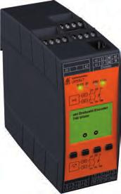
30 Monioring Technique VARIMETER IMD Insulaion monior RN 5897/ RN 5897/010 RP 5898 Produc Descripion The insulaion monior RN 5897/010 of he VARIMETER IMD family provides bes and up o dae insulaion monioring of modern IT sysems in an opimum and sae of he ar way fulfilling he relevan sandards. The device can be used in he mos flexible way for AC, DC and AC/DC sysems even wih large leakage capaciy o earh (PE). The adjusmen of he seing values is simple and user friendly done on 2 roary swiches on he fron of he device. Via display and LEDs he measured value, device parameers and device saus are indicaed easy o read. Wih a sealable ransparen cover he device is proece agains manipulaion. Funcion Diagram U H Your Advanages Prevenive fire and sysem proecion Deecion of symmeric and asymmeric insulaion fauls Quick faul localisaion hrough selecive earh faul deecion o L+ and L- Universal applicaion in non-earhed AC, DC, AC/DC neworks wih up o 300 V nominal volage Easy adjusmen of response values and seing parameer via roaional swich and menu display Suiable for large leakage capaciances up o 1000 μf Opimised reacion ime for large leakage capaciances Monioring also wih volage-free mains Measuring circui L(+)/L(-) wih broken wire deecion (can be swiched off) Proecive conducor PE1/PE2 wih broken wire deecion (can' be swiched off) Feaures Insulaion monioring according o IEC/EN Wih connecion faciliy of an exernal coupling device RP 5898 for volages up o 1000 V Trigger oupu for insulaion faul locaing sysem 2 separae adjusable response hresholds (using e.g. for pre-alarm and Alarm) Seing range of 1s response value (Pre-Alarm): 20 k 2 M Seing range of 2nd response value (Alarm): 1 k 250 k 2 changeover conacs für insulaion failures-pre-alarm and -Alarm Energized or de-energized on rip can be seleced for indicaor relay Display for indicaion of measured value, device parameers and device saus Seing he maximum leakage capaciance o shoren he response ime Auomaic and manual device self-es Alarm sorage selecable Proecion agains manipulaion by sealable ransparen cover Exernal conrol inpu for combined Tes-/Rese-buon 3 wide volage inpu for auxiliary volage Widh 52.5 mm Alarm Pre-Alarm Alarm Pre-Alarm R Earh faul E R R pa A Hyseresis funcion Open circui operaion De-energized on rip Open circui operaion De-energized on rip -12 Manual rese Rese Open circui operaion De-energized on rip Open circui operaion De-energized on rip -12 M593 Approvals and Markings Applicaions AC/DC Insulaion monioring of: Non-earhed AC, DC, AC/DC neworks UPS sysems Neworks wih frequency inverers Baery neworks Neworks wih direc curren drives Hybrid and baery-powered vehicles Mobile generaor ses 39
31 Funcion The device is supplied wih DC auxiliary volage via erminals A1(+) / A2. Swiching on he auxiliary volage (Power-On) is followed by an inernal self-es for 10 sec (see Device es funcions ). The es process is visible in he display. Afer his, measuremen of he insulaion resisance in he measuring circuis begins and he he colour of he backligh changes ino green. Measuring circui (Insulaion measuremen beween erminals L(+) / L(-) and PE1/PE2) The insulaion monior RN 5897 can be operaed eiher wih or wihou coupling device. Max. mains volage and connecion diagrams have o be observed! If he insulaion monior is operaed wihou coupling device he erminals L(+) and L(-) have o be conneced direcly o he volage sysem o be moniored. and he erminals VSG1/L(+) and VSG2/L(-) each have o be bridged (see also operaion wih coupling device). A broken wire deecion ha can be disabled provides a faul signal if boh erminals L(+) and L(-) are no linked by he conneced nework. The ype of nework (AC, DC, 3NAC) has o be seleced. Also he erminals PE1 and PE2 have o be conneced wih 2 separae wires o he proecive earh. An inerrupion of a wire also causes a faul signal (see secion Behavior on fauly connecion ). The monioring of he PE connecion canno be de-acivaed. To measure he insulaion resisance an acive measuring volage wih changing polariy is conneced beween L(+)/L(-) and PE1/PE2.The momenary polariy of he measuring cycle is shown on he display by 2 curser segmens ( MP+ for posiive phase and MP- for negaive phase). The duraion of he posiive and negaive measuring phase depends on he seing of he max. leakage capaciy ( CE[μF] in programming mode), he acual leakage capaciy of he moniored sysem and in DC sysems also on he level and duraion of possible volage variaions. This allows a correc and fas measuremen in differen nework condiions. A he end of a measuring cycle he acual insulaion resisance is produced and indicaed. The acual value is shown on he display. The relays for alarm K1 and pre-alarm K2 swich when dropping under he adjused response values. In addiion he backligh of he display changes o orange color on pre-alarm or o red color on alarm. An asymmeric earh faul eiher o + or - is also indicaed on he display (only in DC- sysems, or wih a faul on he DC-side of a sysem). Manual rese of faul message Using he display menu in programming mode, he manual rese funcion for insulaion failures can be seleced. If manual rese is acivaed he insulaion faul signals of he measuring circui are sored when dropping under he adjused response values also if he insulaion resisance goes back o healhy sae. The minimum value is sored and can be shown on he display. Pressing he Rese buon on he fron side, he alarm signal and he sored minimum value are rese if he acual insulaion resisance is in healhy sae. Indicaor relay for insulaion faul signal For he indicaor relays K1 (conacs , for alarm) and K2 (conacs , for pre-alarm) he funcion can be se in programming mode o energized on rip or de-energized on rip when he insulaion resisance drops below he adjused response value. The saus of he indicaor relays is shown on he display wih he wo cursor segmens "K1" and "K2". When he relay is energized, he corresponding curser lighs up. Trigger oupu for insulaion faul locaing sysem There is an addiional rigger oupu for an insulaion faul deecion sysem on he insulaion monior RN 5897/010. This rigger oupu (Y1-Y2) can be coupled wih he rigger inpu Y1-Y2 of RR 5886 o iniiae auomaic faul locaion wih he insulaion faul locaing sysem, consising of RR 5886 and RR The rigger oupu is acivaed when he measuring value drops under he alarm response value (R E < R A ). As long as i says under he response value or an alarm is sored, he rigger oupu Y1-Y2 remains acive. Funcion Broken wire deecion As described in secion "Measuring circu", he measuring circuis L(+)/L(-) and he proecive conducors PE1/PE2 are consanly moniored for wire breaks no only a Power-On or a manual or occasional auomaic es. The response ime of monioring is only a few seconds. Broken wire deecion beween L(+) and L(-) is performed via coupled alernaing volage. This alernaing volage is shor-circuied if he erminals are conneced o he conneced mains a low-resisance. The device deecs ha he mains o be moniored is properly conneced. Since his broken wire deecion is carried ou wih alernaing volage, large capaciances should be avoided beween L(+) and L(-), since he capaciive reacance of hese capaciances also shor-circuis his alernaing volage. The device would no longer deec a connecion faul on L(+)/L(-). Especially parallel lines should be prevened over larger disances. If larger capaciances beween L(+)/L(-) canno be avoided or if he coupled alernaing volage inerferes wih he sysem, he broken wire deecion can be de-acivaed using he display menu in programming mode. Monioring deacivaed, monioring only during device es or coninuous monioring (every 2 minues for 10 sec) are he possible opions. If he broken wire deecion on L(+)/L(-) is de-acivaed no AC volage is injeced. The broken wire deecion on PE1/PE2 canno be de-acivaed. Device es funcions Principally, 2 differen es funcions are implemened: The "self-es" and he "expanded es": The self-es of he device is performed auomaically afer Power-On and every full operaing hours. I can also be riggered manually a any ime by pressing he "Tes" buon a he device fron for 2 sec. Wih he self-es, conrary o he expanded es, he saus of he Indicaor relays is no affeced; he sequence is as follows: The display backligh colour changes ino orange. For approx.. 2 s all pixels and segmens of he LCD are shown. Afer ha he ex Tes1 comes up and he measuring pulse is swiched for approx. 4 s o negaive es phase. The polariy of he es volage is also indicaed on he display by curser segmens. Wihin hese 4 s he inernal measuring circui is checked for failures. Then he measuring pulse is swiched for approx.. 4 s o posiive es phase and more inernal ess ake place. If no failures urned up and had been recognized, he measuremen coninuous. The exended es procedure is sared when during or a he end of he above described self-es he es buon is pressed again for 2 s. The sequence is similar o he self-es (2 measuring phases of 4 s each) bu in addiion he oupu relays go in alarm saed. The display shows Tes2. The es phases of he exended es will be repeaed coninuously. Pressing he rese buon again for 2 s will sop he exended es immediaely. The device sars he insulaion measuremen again. Behaviour wih inernal device fauls If inernal device fauls were deeced during he es funcion, he display backligh changes ino red and an error messages (failure code: In.1 ) is indicaed. The indicaor relays K1 and K2 swich o he alarm sae. Behavior on fauly connecion When deecing broken wire on erminals L(+)/L(-), he measuremen is disabled. The reacion ime could be up o 2 min. The monioring relays K1 and K2 go in alarm sae, he backligh changes o red. The display shows he faul message L+/L-. Afer removing he inerrupion he faul is auomaically rese (max. reacion ime up o 2 min) and he measuremen of he insulaion resisance is coninued. Sored alarm values remain sored. An inerrupion of he proecive earh connecions PE1/PE2 causes he same reacion as inerruping he measuring circui, only he display shows PE1-PE2. Exernal conrol inpu To erminals X1/X2 an exernal combined Tes-/Rese buon can be conneced. If he erminals X1/X2 are bridged for approx.. 1 s he es mode is sared. This has he same funcion as pressing he inernal es buon. When bridging X1/X2 for > 3 s, a sored alarm will be rese. This has he same funcion as pressing he inernal rese buon. 40
32 Funcion Connecion of an exernal coupling device An exernal coupling device RP 5898 can be conneced o exend he inpu volage range of he moniored volage sysem on RN 5897/010. The erminals wih he same legend of he insulaion monior and he coupling device (VSG1, VSG2, L(+), L(-)) are conneced ogeher. The nework o be moniored is conneced o erminals (+) und L2(-) on he coupling device. Using he display menu in programming mode he connecion of he coupling device has o be seleced and acivaed. The broken wire deecion is acive on he erminals (+)/L2(-) on he coupling device. A broken wire beween coupling device and insulaion monior canno be deeced immediaely bu he measured values on inerrupion of 1 or 2 wires beween coupling device and insulaion monior are much lower as he real values, which will cause an early response of he device. Programming/seing of parameers/se-up of he insulaion monior The response values for alarm and pre-alarm can be adjused via 2 roary swiches R A and R pa on he fron of he device. New seing are immediaely acive and do no require a resar of he uni. More seings can be done wih he 3 buons and he display menu in programming mode. To sar he programming mode, he buon Se/ESC has o be pressed for approx. 2 s. To avoid unauhorized manipulaion, his buon as well as he roary swiches R A and R pa are locaed behind a sealable ransparen cover. When he device changes o programming mode, he measuremen is sopped, he display back ligh changes o orange color and he firs parameer is displayed. To scroll he differen parameers, he buon Se/ ESC has o be pressed shor. Wih he 2 scroll buons (Scroll-Up and Scroll-Down ) he seings can be modified. The firs parameer is he broken wire deecion in he measuring circui BrWiD. Possible seing are coninuously on ( on ), coninuously off ( off ) or only acive during self-es. The defaul is on. The second parameer is alarm memory Mem.. Here are 2 opions available manual rese ( on ) und auo rese ( off ). The defaul value is off. The hird parameer is he relay operaion principle Rel. Seings are: de-energized on rip ( n.c. ) and energized on rip ( n.o. ). The defaul value is n.c.. The fourh parameer is he ype of nework connecion Ne. Selecion are AC Nework( Ac ),DC-Nework ( dc ) or 3NAC-Nework ( 3nAc ). The defaul value is Ac. The fifh parameer is he seing of he maximum leakage capaciy ( CE[μF] ). This can be adjused o 30 μf ( 30 ), 100 μf ( 100 ), 300 μf ( 300 ) and 1000 μf ( 1000 ). The defaul value is 30. The device allow he connecion of a coupling device, he sixh parameer acivaes ( on ) or de-acivaes ( off ) he coupling device. The leave he programming mode he buon Se/ESC has o be pressed for 2 s. The seings will be acivaed and sored permanenly. Afer ha he device makes a resar similar o power on. Circui Diagram U H VSG1 X1 X2 L(+) L(-) L(+) L(-) PE1 PE2 Connecion Terminals VSG2 A1(+) 12 A2 Y1 Y PE1 PE2 M455 Terminal designaion Signal designaion A1(+), A2 Auxiliarx volage AC or DC L(+), L(-), VSG1, VSG2 Connecion for measuring cirui or Connecion for coupling device PE1, PE2 Connecion for proecive conducor X1, X2 Conrol inpu (combined exernal Tes- and Rese-inpu) Y1, Y2 Alarm rigger oupu for insulaion faul locaing sysem, 12, 13 Alarm signal relay K1(1 changeover conac) 21, 22, 23 Prewarning signal relay K2 (1 changeover conac) Defaul-Seing of Parameers Nr. Parameer Defaul-Se Broken wire deec in measuring circui 1 on Broken Wire Deec Soring insulaion faul message 2 off Memory Swiching mode of oupu relays Relay Power supply ype Ne Max. line capaciance CE[μF] Ex. coupling device VSG n.c. (normally closed) de-energized on rip AC 30 off 41
 Alarm (measured value below alarm response value, device failure, connecion failure) Orange: Warning")
33 Indicaors connecion measuring cirui or Coupling device rigger oupu auxiliary volage Indicaors The colour of he backligh indicaes he operaing saus of he device. Off: Green: Red: No auxiliary volage conneced Normal operaion (Insulaion resisance in healhy sae) Alarm (measured value below alarm response value, device failure, connecion failure) Orange: Warning (measured value below pre-alarm response value, es mode, Parameer se-up mode) Acual value display The acual insulaion resisance R E [k ] is displayed. If he acual value is R E < 10 kohm, he value in kohm is displayed wih 1 decimal place. Wih values 10 kohm R E < 500 kohm he display shows he value wihou decimal place, wih values 500 kohm R E < 1 MOhm he value is rounded o 10 kohm. Insulaion resisance values 1 MOhm R E < 2 MOhm are displayed in MOhm wih one decimal place. If he resisance is R E > 2 MOHm he display indicaes ---- showing he value is higher he 2 MOhm. In a DC Nework an asymmeric insulaion resisance o + or - is indicaed by displaying R E +[k ] or R E -[k ] By pressing he scroll buons (Scroll-Up und Scroll-Down ) more measured values can be shown. Anoher value is he mains volage on L(+)/L(-).This is indicaed wih U N [V AC ] or U N [V DC ] in V depending on he ype of nework and volage. If he uni is conneced single pole o a 3NAC nework he mains volage canno be measured. Wih his seing he volage value is no displayed. When manual rese is seleced, he display shows he minimum sored value of he resisance R M [M ] or R M [k ] afer he value dropped below he response value also when he value goes back o healhy sae. The sored minimum value will only be rese when acknowledging he sored Alarm signal (wih he rese buon). Also he firmware version can be displayed. exernal conrol inpu RN 5897/010 Indicaor relay alarm and pre-alarm proecive conducor M597 Posiive measuremen phase acive (MP+) Pre-Alarm monioring relay K2 energized Negaive measuremen phase acive (MP-) Alarm monioring relay K1 energized 42
34 Indicaors Display-Indicaion Measuring- resp. display value Error Indicaion Display-Indicaion Failure cause Failure recovery Insulaing resisance in k resp. M ( ---- complies RE 2 M ) Asymmerical insulaing resisance in k agains L+ or L- a DC-mains Measured mains volage in V a AC- or DC-mains Sored min. insulaing resisance in k resp. M Laes firmware-version Broken wire deecion on L(+)/L(-). Broken wire deecion on PE1/PE2. Inernal failure deeced in es mode Fauly calibraion values deeced in device memory. Check measuring circui L(+) and L (-) Check proecive conducor connecions PE1 and PE2 Press es buon again or resar he uni by inerruping he auxiliary supply emporarily. If he faul remains permanen, send device back o manufacurer for examinaion. Send device back o manufacurer for recalobraion and examinaion. Display-Indicaion Tes funcion Display-Tes Selfesing (measuring swiching, measuring volage, inernal ess) Advanced Tes (addiional conrol of indicaor relay) 43
35 Noes In one volage sysem only one insulaion monior can be used. This has o be observed when inerconnecing wo separae sysems. Device erminals PE1 and PE2 mus always be conneced via separae lines o differen erminal poins of he proecive-conducor sysem. The main measuring circui can be conneced wih is erminals L(+) and L(-) boh o he DC and also AC side of a mixed nework; i is done mos pracically where he primary incoming power supply akes place e.g. wih baery neworks wih conneced inverers on he DC side, wih Generaors/ Transformers wih conneced Recifiers or inverers on he AC-side. To monior a 3NAC sysem he device can be conneced single pole, (L(+) and L(-) are bridged, o he neural of he 3p4w sysem. The 3 phases have a low-ohmic (approx. 3 5 Ohm) connecion via he ransformer windings so also insulaion failures of he no direcly conneced phases are deeced. Via he display menu in programming mode he correc ype of nework needs o be seleced (see Connecion Examples ). The measuring circui of he RN 5897/010 are designed for leakage capaciies up o 1000 μf. The measuremen of he insulaion resisance will no be influenced bu for he measuring phases longer ime periods are necessary as wih smaller capaciies. If he max. possible leakage capaciy is known, he device can be adjused o he required lower level, which will reduce he response ime and measuremen ime. Please do no connec exernal volage o erminals X1/X2. The conrol mus only be made by bridging X1 and X2. The rigger oupu Y1/Y2 a RN 5897/010 is galvanic separaed from he res of he circui. I deermined o be conneced o a DOLD insulaion faul locaion sysem RR5886 and RR5887. Please do no connec exernal volages. ATTENTION! The device mus no be operaed wihou PE1/PE2 connecion!! Before checking insulaion and volage, disconnec he monioring device RN 5897 from he power source! WARNING The device moniors HIGH-VOLTAGE! Cauion High-Volage when working on he device! Disconnec all power supplies before servicing equipmen! 44
36 Running char Press buon Se/ESC >2s Se parameers Press buon Se/ESC Press buon Scroll Down Press buon Scroll Up Parameer 1: Broken wire deec in measuring circui BrWiD (Broken Wire Deec) Defaul: on Parameer 1: Broken wire deec in measuring circui BrWiD (Broken Wire Deec) off Parameer 1: Broken wire deec in measuring circui BrWiD (Broken Wire Deec) ES Parameer 2: Soring insulaion faul message Mem. (Memory) Defaul: off Parameer 2: Soring insulaion faul message Mem. (Memory) on Parameer 3: Swiching mode of oupu relays Rel. (Relay) Defaul: n.c. Parameer 3: Swiching mode of oupu relays Rel. (Relay) n.o. Parameer 4: Power supply ype Ne Defaul: Ac Parameer 4: Power supply ype Ne dc Parameer 4: Power supply ype Ne 3nAc Parameer 5: Max. line capaciance C E [μf] Defaul: 30 Parameer 5: Max. line capaciance C E [μf] 100 Parameer 5: Max. line capaciance C E [μf] 300 Parameer 5: Max. line capaciance C E [μf] 1000 Parameer 6: Ex. coupling device VSG Defaul: off Parameer 6: Ex. coupling device VSG on Press buon Se/ESC >2s End of programming 45
37 Technical Daa Measuring cirui L(+)/L(-) o PE1/PE2 (wihou coupling device) Volage range U N : DC 0... max. 300 V; AC 0... max. 250 V Frequency range: DC or Hz Max. line capaciance: 1000 μf Inernal resisance (AC / DC): > 90 kω Measuring volage: approx. ± 90 V Max. mesured curren (R E = 0): < 1,10 ma Response inaccuracy: ± 15 % ± 1.5 kω IEC Response value hyseresis: approx %; min. + 1 kω On delay a C E = 1μF, R E of o 0,5 * response value: < 30 s Measuring ime: A C E = μf, R E from o 1000 k, R E from o 100 k, R E from o 1 k : see characerisics Response values Pre-warning ( R pa ): kω: Alarm ( R A ) kω: each adjusable via roaional swiches Response value broken wire deecion L(+)/L(-): Response value brokenwire deecion PE1/PE2: > approx. 90 k > approx. 0.5 k Measuring cirui (+)/L2(-) o PE1/PE2 (wih coupling device RP 5898) Volage range U N : DC 0... max V; AC 0... max. 760 V Frequency range: DC or Hz Max. line capaciance: 1000 μf Innenwidersand (AC / DC): > 240 kω Messspannung: approx. ± 90 V Max. mesured curren (R E = 0): < 0,40 ma Response inaccuracy: ± 15 % ± 1.5 kω IEC Response value hyseresis: approx %; min. + 1 kω On delay a C E = 1μF, R E of o 0,5 * response value: < 30 s Measuring ime: A C E = μf, R E from o 1000 k, R E from o 100 k, R E from o 1 k : see characerisics Response values Pre-warning ( R pa ): kω: Alarm ( R A ) kω: each adjusable via roaional swiches Response value broken wire deecion (+)/L2(-): Response value broken wire deecion PE1/PE2: Max. wire lengh beween insulaion monior and coupling device: Auxiliary volage inpu A1(+)/A2 > approx. 500 k > approx. 0.5 k < 0,5 m Nom. Volage Volage range Frequency range AC/DC V AC V Hz; DC 48 % W* ) DC V W* ) 5 % AC/DC V AC V Hz; DC 48 % W* ) DC V W* ) 5 % DC V DC V W* ) 5 % * ) W = permied residual ripple of auxiliary supply Technical Daa Nominal consumpion: DC 12 V, 24 V, 48 V: AC 230 V: max. 3 W max. 3.5 VA Conrol inpu X1/X2 for exernal kombiniere Tes-/Rese-Tase Curren flow: approx. 3 ma No-load operaion volage X1 o X2: ca. 12 V Permissible wire lengh: < 50 m Acivaion ime for es signal: approx. 1 s Acivaion ime for rese signal: > 3 s Oupus Indicaor conac: 2 x 1 changeover conac for Alarm (K1) and Pre-Alarm (K2) energized or de-energized on rip (programmable) Thermal curren I h : 4 A Swiching capaciy o AC 15: NO conac: 5 A / AC 230 V IEC/EN NC conac: 2 A / AC 230 V IEC/EN o DC 13: 2 A / DC 24 V IEC/EN Elecrical life a 5 A, AC 230 V: 1 x 10 5 swiching cycles Shor circui srengh max. fuse raing: 4 A gl IEC/EN Mechanical life: 50 x 10 6 swiching cycles General Daa Operaing mode: Coninuous operaion Temperaure range Operaion: C (a range 0-30 C limied funcion of he LCD displaye) Sorage: C Aliude: < m IEC Clearance and creepage disances Raed insulaion volage: 300 V Overvolage caegory: III raed impuls volage / polluion degree: IEC measuring circui L(+)/L(-) o auxiliary volage A1(+)/A2 and indicaor relay conacs K1, K2 and rigger oupu Y1/Y2: 4 kv / 2 auxiliary volage A1(+)/A2 o indicaor relay conacs K1, K2 und rigger oupu Y1/Y2: 4 kv / 2 indicaor relay conac K1 o indicaor relay conacs K2: 4 kv / 2 rigger oupu Y1/Y2 o indicaor relay conacs K1, K2: 4 kv / 2 Insulaion es volage Rouine es: AC 2,5 kv; 1 s EMC Elecrosaic discharge (ESD): 8 kv (air) IEC/EN HF irradiaion: 80 MHz 1 GHz: 20 V / m IEC/EN GHz 2.7 GHz: 10 V / m IEC/EN Fas ransiens: 2 kv IEC/EN Surge volage beween wires for power supply: 1 kv IEC/EN beween wire and ground: 2 kv IEC/EN HF-wire guided: 20 V IEC/EN Inerference suppression: Limi value classe B EN 550 Degree of proecion Housing: IP 40 IEC/EN Terminals: IP 20 IEC/EN Housing: Thermpolasic wih V0 behaviour according o UL subjec 94 Vibraion resisance: Ampliude 0.35 mm, Frequency Hz, IEC/EN Climae resisance: 30 / 060 / 04 IEC/EN
38 Technical Daa Terminal designaion: EN Wire connecion DIN /-2/-3/-4 Cross secion: mm² (AWG 20-10) solid or mm² (AWG 20-10) sranded wire wihou ferrules 0,5... 2,5 mm² (AWG 20-10) sranded wire wih ferrules Sripping lengh: 6.5 mm Wire fixing: Cross-head screw / M3 box erminals Fixing orque: 0.5 Nm Mouning: DIN rail IEC/EN Weigh: approx. 205 g Accessories RP5898: Aricle number: Coupling device for RN /010 Exension of nominal volage range U N o DC max V, AC max. 760 V Weigh: approx. 0 g Dimensions - Widh x heigh x deph: 70 x 90 x 71 mm insulaion monior connecion Dimensions Widh x heigh x deph: 52.2 x 90 x 71 mm Sandard Types RN DC V Aricle number: Auxiliary volage: DC V RN AC/DC V Aricle number: Auxiliary volage: AC/DC V RN AC/DC V Aricle number: Auxiliary volage: AC/DC V Oupus: 1 changeover conac for pre-warning 1 changeover conac for alarm 20 k 2 M 1 k 250 k Seing range pre-warning: Seing range alarm: Trigger oupu for insulaion faul locaing sysem Wih connecion faciliy of a coupling device RP 5898 Adjusable line capaciance Energized or de-energized on rip Selecion of ype of nework Widh: 52.5 mm measuring cirui M599 Ordering Example for varians RN / _ AC/DC V 20 k 2 M 1 k 250 k Seing range alarm Seing range Pre-warning Auxiliary volage Varian, if required Conacs Type Connecion Example *1) Auxiliary volage U H (A1(+)/A2) ) can also be sourced from he moniored volage sysem. The volage range of he auxiliary supply has o be aken ino accoun. *2) Conrol inpu X1/X2 for exernal combined Tes-/Rese-buon: Conrol approx. 1 s: Tes funcion Conrol > 3 s: Rese funcion 47
39 Connecion Example L2 L3 N Ungrounded mains 3N AC 400V/230V Hz U N L2 L3 Ungrounded mains 3 AC 690V/400V Hz UN VSG1 L(+) X1 L(-) VSG2 Y1 Y2 RN5897/010 UH *1) A1(+) X2 PE1 PE A2 Seing of ype of nework: 3N AC (+) L2(-) Seing of ype of nework: AC Exernal coupling device: RP5898 ON VSG1 L(+) L(-) VSG2 VSG1 L(+) L(-) VSG2 UH *1) Y1 Y2 A1(+) A2 *2) exernal combined es/rese buon RN5897/010 PE X1 X2 PE1 PE M671 *2) Exernal combined es/rese buon PE M625 Single phase mains, isolaed from earh AC V Hz Single phase mains, isolaed from earh AC V Hz L2 UN L2 U N VSG1 L(+) L(-) VSG2 UH *1) Y1 Y2 A1(+) A2 Seing of ype of nework: AC Exernal coupling device: OFF (+) RP5898 L2(-) Seing of ype of nework: DC Exernal coupling device: ON X1 RN5897/010 X2 PE1 PE VSG1 L(+) VSG1 L(+) L(-) L(-) VSG2 VSG2 UH *1) Y1 Y2 A1(+) A2 *2) Exernal combined es/rese buon RN5897/010 X1 X2 PE1 PE M617 *2) Exernal combined es/rese buon PE M623 *1) Auxiliary volage U H (A1(+)/A2) ) can also be sourced from he moniored volage sysem. The volage range of he auxiliary supply has o be aken ino accoun. *2) Conrol inpu X1/X2 for exernal combined Tes-/Rese-buon: Conrol approx. 1 s: Tes funcion Conrol > 3 s: Rese funcion 48
40 Connecion Example L+ Ungrounded DC nework DC V L+ Ungrounded DC nework DC V L- UN L- U N VSG1 L(+) L(-) VSG2 UH *1) Y1 Y2 A1(+) A2 Seing of ype of nework: DC Exernal coupling device: OFF (+) L2(-) Seing of ype of nework: DC Exernal coupling device: RP5898 ON VSG1 L(+) L(-) VSG2 X1 RN5897/010 X2 PE1 PE VSG1 L(+) L(-) VSG2 UH *1) Y1 Y2 A1(+) A2 *2) exernal combined es/rese buon RN5897/010 PE M619 X1 *2) Exernal combined es/rese buon X2 PE1 PE PE M621 *1) Auxiliary volage U H (A1(+)/A2) ) can also be sourced from he moniored volage sysem. The volage range of he auxiliary supply has o be aken ino accoun. *2) Conrol inpu X1/X2 for exernal combined Tes-/Rese-buon: Conrol approx. 1 s: Tes funcion Conrol > 3 s: Rese funcion 49
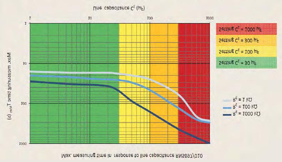
41 Characerisics M605 50
42 Monioring Technique VARIMETER IMD Insulaion monior RN 5897/ Your Advanages Prevenive fire and sysem proecion Deecion of symmeric and asymmeric insulaion fauls Universal applicaion in non-earhed AC, DC, AC/DC neworks wih up o 300 V nominal volage Easy adjusmen of response values and seing parameer via roaional swich Suiable for large leakage capaciances up o 30 μf Monioring also wih volage-free mains Measuring circui L(+)/L(-) wih broken wire deecion (can be swiched off) Proecive conducor PE1/PE2 wih broken wire deecion (can' be swiched off) No addiional coupling device required Produc Descripion The insulaion monior RN 5897/300 of he VARIMETER IMD family provides bes and up o dae insulaion monioring of modern IT sysems in an opimum and sae of he ar way fulfilling he relevan sandards. The device can be used in he mos flexible way for AC, DC and AC/DC sysems. The adjusmen of he seing values is simple and user friendly done on 3 roary swiches on he fron of he device. Via mulicolor LED he device saus is indicaed easy o read. Wih a sealable ransparen cover he device is proece agains manipulaion. Feaures Insulaion monioring according o IEC/EN separae adjusable response hresholds (using e.g. for pre-alarm and Alarm) Seing range of 1s response value (Pre-Alarm): 20 k 1 M : Seing range of 2nd response value (Alarm): 10 k 250 k 2 changeover conacs für insulaion failures-pre-alarm and -Alarm Energized or de-energized on rip can be seleced for indicaor relay LED for saus indicaion Auomaic and manual device self-es Alarm sorage selecable Proecion agains manipulaion by sealable ransparen cover Exernal conrol inpu for combined Tes-/Rese-buon 3 wide volage inpu for auxiliary volage Widh 52.5 mm Approvals and Markings AC/DC Applicaions Insulaion monioring of: Non-earhed AC, DC, AC/DC neworks UPS sysems Neworks wih frequency inverers Baery neworks Neworks wih direc curren drives Hybrid and baery-powered vehicles Mobile generaor ses 51
43 Funcion The device is supplied wih DC auxiliary volage via erminals A1(+) / A2. Swiching on he auxiliary volage (Power-On) is followed by an inernal self-es for 10 sec (see Device es funcions ). The es process is visible in he saus LED. Afer his, measuremen of he insulaion resisance in he measuring circuis begins and he he colour of he saus LED changes o green. Measuring circui (Insulaion measuremen beween erminals L(+) / L(-) and PE1/PE2) The erminals L(+) and L(-) are conneced direcly o he volage sysem o be moniored. A broken wire deecion creaes a faul signal if here is no low-ohmic connecion beween boh erminals. The ype of nework (AC, DC, 3NAC) has o be seleced. Also he erminals PE1 and PE2 have o be conneced wih 2 separae wires o he proecive earh. An inerrupion of a wire also causes a faul signal (see secion Behavior on fauly connecion ). The monioring of he PE connecion canno be de-acivaed. To measure he insulaion resisance an acive measuring volage wih changing polariy is conneced beween L(+)/L(-) and PE1/PE2. The duraion of he posiive and negaive measuring phase depends on he acual leakage capaciy of he moniored sysem and in DC sysems also on he level and duraion of possible volage variaions. This allows a correc and fas measuremen in differen nework condiions. A he end of a measuring cycle he acual insulaion resisance is produced and indicaed. The relays for alarm K1 and pre-alarm K2 swich when dropping under he adjused response values. In addiion he LED changes o orange color on pre-alarm or o red color on alarm. Manual rese of faul message The roary swich "UN" is devided in 2 secions. So addiional o he ype of volage sysem also manual or auorese can be seleced. (Alarm soring: manual rese, no alarm soring: auo rese). If manual rese is acivaed he insulaion faul signals of he measuring circui are sored when dropping under he adjused response values also if he insulaion resisance goes back o healhy sae. Pressing he Rese buon on he fron side for 2 s, he alarm signal are rese if he acual insulaion resisance is in healhy sae. Indicaor relay for insulaion faul signal For he indicaor relays K1 (conacs , for alarm) and K2 (conacs , for pre-alarm) he funcion energized on rip or de-energized on rip can be se via pre-alarm roaional swich "R pa " when he insulaion resisance drops below he adjused response value. Broken wire deecion As described in secion "Measuring circu", he measuring circuis L(+)/L(-) and he proecive conducors PE1/PE2 are consanly moniored for wire breaks no only a Power-On or a manual or occasional auomaic es. The response ime of monioring is only a few seconds. Broken wire deecion beween L(+) and L(-) is performed via coupled alernaing volage. This alernaing volage is shor-circuied if he erminals are conneced o he conneced mains a low-resisance. The device deecs ha he mains o be moniored is properly conneced. Since his broken wire deecion is carried ou wih alernaing volage, large capaciances should be avoided beween L(+) and L(-), since he capaciive reacance of hese capaciances also shor-circuis his alernaing volage. The device would no longer deec a connecion faul on L(+)/L(-). Especially parallel lines should be avoided over larger disances. If larger capaciances beween L(+)/L(-) canno be avoided or if he coupled alernaing volage inerferes wih he sysem, he broken wire deecion can be de-acivaed using alarm roary swich "R A ". Monioring deacivaed or coninuous monioring (every 2 minues for 10 sec) are he possible opions. If he broken wire deecion on L(+)/L(-) is de-acivaed no AC volage is injeced. The broken wire deecion on PE1/PE2 canno be de-acivaed. Funcion Device es funcions Principally, 2 differen es funcions are implemened: The "self-es" and he "expanded es": The self-es of he device is performed auomaically afer Power-On and every full operaing hours. I can also be riggered manually a any ime by pressing he "Tes" buon a he device fron for 2 sec. Wih he self-es, conrary o he expanded es, he saus of he Indicaor relays is no affeced; he sequence is as follows: The self-es is indicaed via LED wih orange flash code 1. For approx. 4 s o negaive es phase. Wihin hese 4 s he inernal measuring circui is checked for failures. Then he measuring pulse is swiched for approx.. 4 s o posiive es phase and more inernal ess ake place. If no failures urned up and had been recognized, he measuremen coninuous. The exended es procedure is sared when during or a he end of he above described self-es he es buon is pressed again for 2 s. The sequence is similar o he self-es (2 measuring phases of 4 s each) bu in addiion he oupu relays go in alarm saed. The LED shows orange flash code 2. The es phases of he exended es will be repeaed coninuously. Pressing he rese buon again for 2 s will sop he exended es immediaely. The device sars he insulaion measuremen again. Behaviour wih inernal device fauls If inernal device fauls were deeced during he es funcion, he LED flashes coninuously red. The indicaor relays K1 and K2 swich o he alarm sae. Behavior on fauly connecion When deecing broken wire on erminals L(+)/L(-), he measuremen is disabled. The reacion ime could be up o 2 min. The monioring relays K1 and K2 go in alarm sae, he LED indicaes he red flash code 1. Afer removing he inerrupion he faul is auomaically rese (max. reacion ime up o 2 min) and he measuremen of he insulaion resisance is coninued. Sored alarm values remain sored. An inerrupion of he proecive earh connecions PE1/PE2 causes he same reacion as inerruping he measuring circui, only he LED indicae he red flash code 2. Exernal conrol inpu To erminals X1/X2 an exernal combined Tes-/Rese buon can be conneced. If he erminals X1/X2 are bridged for approx.. 1 s he es mode is sared. This has he same funcion as pressing he inernal es buon. When bridging X1/X2 for > 3 s, a sored alarm will be rese. This has he same funcion as pressing he inernal rese buon. Programming/seing of parameers/se-up of he insulaion monior All seing are done wih 3 roary swiches on he fron of he uni. To avoid unauhorized manipulaion of he seings, all 3 swiches are locaed behind a sealable ransparen cover. The firs roary swich R A ses he response value for alarm. In addiion i is divided in 2 secions. If he seing posiion is in he firs secion he broken wire deecion is permanen enabled, if he seing posiion is in he second secion he broken wire deecion is permanen disabled. The second roary swich R pa ses he response value for pre-alarm. In addiion i is also divided in 2 secions. If he seing posiion is in he firs secion, he relay oupu funcion is de-energized on rip, if he seing posiion is in he second secion, he relay oupu funcion is energized on rip. The hird roary swich UN selecs he ype of nework connecion. I is also divided in 2 secions. If he seing posiion is in he firs secion, he uni is on auo rese, if he seing posiion is in he second secion, he uni is on manual rese. New seings are acceped wihou resar of he device. 52
44 Funcion Diagram Circui Diagram L(+) L(-) A1(+) A2 U H Alarm Pre-Alarm Alarm Pre-Alarm Hyseresis funcion Open circui operaion Open circui operaion -12 Manual rese R Earh faul E R R pa A De-energized on rip De-energized on rip -12 Rese Open circui operaion De-energized on rip Open circui operaion De-energized on rip -12 Connecion Terminals Terminal designaion A1(+), A2 L(+), L(-) PE1, PE2 X1, X2 U H, 12, 13 21, 22, 23 X1 X2 L(+) L(-) PE1 PE PE1 PE M454 Signal designaion Auxiliarx volage AC or DC Connecion for measuring cirui Connecion for proecive conducor Conrol inpu (combined exernal Tes- and Rese-inpu) Alarm signal relay K1 (1 changeover conac) Prewarning signal relay K2 (1 changeover conac) M593 Flashing Codes LED "ERR" LED-colour: orange self es exended es LED-colour: red inernal sysem error connecion failure measuring cirui L(+)/L(-) connecion failure proecive conducor PE1/PE2 M607 53
45 Indicaors Error Indicaion connecion measuring cirui auxiliary volage Flash code red Saus-LED Failure cause Failure recovery 1 Broken wire deecion on L(+)/L(-). Check measuring circui L(+) and L (-) 2 coninously flashing Broken wire deecion on PE1/PE2. Inernal failure deeced in es mode Check proecive earh connecions PE1 and PE2 Press es buon again or resar he uni by inerruping he auxiliary supply emporarily. If he faul remains permanen, send device back o manufacurer for examinaion. coninously flashing Fauly calibraion values deeced in device memory. Send device back o manufacurer for recalobraion and examinaion. Indicaor relay alarm and pre-alarm proecive conducor M609 exernal conrol inpu Indicaors Noes The operaional saus of he device is indicaed on a 3-colour LED: Off: Green: Red: orange: orange flashing: red flashing: Flash code orange Saus-LED 1 2 No auxiliary volage conneced Normal operaion (Insulaion resisance in healhy sae) Alarm (measured value below alarm response value) Warning (measured value below pre-alarm response value) Tes mode procedure (see flashing code diagramm) Failure code (see flashing code diagramm) Descripion Selfes (measuring circui, measuring volage, inernal ess) Advanced Tes (addiional conrol of indicaor relays) In one volage sysem only one insulaion monior can be used. This has o be observed when inerconnecing wo separae sysems. Device erminals PE1 and PE2 mus always be conneced via separae lines o differen erminal poins of he proecive-conducor sysem. The main measuring circui can be conneced wih is erminals L(+) and L(-) boh o he DC and also AC side of a mixed nework; i is done mos pracically where he primary incoming power supply akes place e.g. baery neworks wih conneced inverers on he DC side, wih Generaors/ Transformers wih conneced Recifiers or inverers on he AC-side. To monior a 3NAC sysem he device can be conneced single pole, (L(+) and L(-) are bridged, o he neural of he 3p4w sysem. The 3 phases have a low-ohmic (approx. 3 5 Ohm) connecion via he ransformer windings so also insulaion failures of he no direcly conneced phases are deeced. Via he roaional swich "UN" he correc ype of nework needs o be seleced (see Connecion Examples ). Please do no connec exernal volage o erminals X1/X2. The conrol mus only be made by bridging X1 and X2. ATTENTION! The device mus no be operaed wihou PE1/PE2 connecion!! Before checking insulaion and volage, disconnec he monioring device RN 5897 from he power source! WARNING The device moniors HIGH-VOLTAGE! Cauion High-Volage when working on he device! Disconnec all power supplies before servicing equipmen! 54
46 Technical Daa Measuring cirui L(+) / L(-) o PE1 / PE2 Volage range U N : DC 0... max. 300 V; AC 0... max. 300 V Frequency range: DC or Hz Max. line capaciance: 30 μf Inernal resisance (AC / DC): > 120 kω Measuring volage: approx. ± 90 V Max. mesured curren (R E = 0): < 0,80 ma Response inaccuracy: ± 15 % ± 1.5 kω IEC Response value hyseresis: approx %; min. + 1 kω On delay a C E = 1μF, R E of o 0.5 * response value: Measuring ime: A C E = 1 30 μf, R E from o 1000 k, R E from o 100 k, R E from o 1 k : Response values: Pre-warning ( R pa ): kω: Alarm ( R A ) kω: each adjusable via roaional swiches Response value broken wire deecion L(+)/L(-): Response value broken wire deecion PE1/PE2: Auxiliary volage inpu A1(+)/A2 1 s (a seing 3N AC) < 5 s (a seing AC, DC) see characerisics > approx. 30 k > approx. 0,5 k Nom. Volage Volage range Frequency range AC/DC V AC V Hz; DC 48 % W* ) DC V W* ) 5 % AC/DC V AC V Hz; DC 48 % W* ) DC V W* ) 5 % DC V DC 9, V W* ) 5 % * ) W = permied residual ripple of auxiliary supply Nominal consumpion: DC 24 V, 48 V: AC 230 V: max. 3 W max. 3.5 VA Conrol inpu X1/X2 for exernal kombiniere Tes-/Rese-Tase Curren flow: approx. 3 ma No-load operaion volage X1 o X2: ca. 12 V Permissible wire lengh: < 50 m Acivaion ime for es signal: approx. 1 s Acivaion ime for rese signal: > 3 s Oupus Indicaor conac: 2 x 1 changeover conac for Alarm (K1) and Pre-Alarm (K2) energized or de-energized on rip (programmable) Thermal curren I h : 4 A Swiching capaciy o AC 15: NO conac: 5 A / AC 230 V IEC/EN NC conac: 2 A / AC 230 V IEC/EN o DC 13: 2 A / DC 24 V IEC/EN Elecrical life a 5 A, AC 230 V: 1 x 10 5 swiching cycles Shor circui srengh max. fuse raing: 4 A gl IEC/EN Mechanical life: 50 x 10 6 swiching cycles Technical Daa General Daa Operaing mode: Coninuous operaion Temperaure range: Operaion: C Aliude: < m IEC Clearance and creepage disances Raed insulaion volage: 300 V Overvolage caegory: III raed impuls volage / polluion degree: IEC measuring circui L(+)/L(-) o auxiliary volage A1(+)/A2 and indicaor relay conacs K1, K2: 4 kv / 2 auxiliary volage A1(+)/A2 o indicaor relay conacs K1, K2: 4 kv / 2 indicaor relay conac K1 o indicaor relay conacs K2: 4 kv / 2 EMC Elecrosaic discharge (ESD): 8 kv (air) IEC/EN HF irradiaion: 80 MHz 1 GHz: 20 V / m IEC/EN GHz 2.7 GHz: 10 V / m IEC/EN Fas ransiens: 2 kv IEC/EN Surge volage beween wires for power supply: 1 kv IEC/EN beween wire and ground: 2 kv IEC/EN HF-wire guided: 20 V IEC/EN Inerference suppression: Limi value classe B EN 550 Degree of proecion Housing: IP 40 IEC/EN Terminals: IP 20 IEC/EN Housing: Thermpolasic wih V0 behaviour according o UL subjec 94 Vibraion resisance: Ampliude 0.35 mm, Frequency Hz, IEC/EN Climae resisance: 40 / 070 / 04 IEC/EN Terminal designaion: EN Wire connecion Cross secion: solid/sranded mm 2 Sranded ferruled: mm 2 Muliple wire connecion: mm 2 (2 wires wih same cross secion) Sripping lengh: 6.5 mm max. fixing orque: 0.5 Nm Wire fixing: box erminal wih cross recess screw Mouning: DIN rail IEC/EN Weigh: approx. 200 g Dimensions Widh x heigh x deph: Classificaion o DIN EN x 90 x 71 mm Vibraion and shock resisance: Caegory 1, Class B IEC/EN Proecive coaing of he PCB: No 55
47 Sandard Types RN /300 AC/DC V Aricle number: Auxiliary volage: AC/DC V Oupus: 1 changeover conac for pre-warning 1 changeover conac for alarm Seing range pre-warning: 20 k 1 M Seing range alarm: 10 k 250 k Max. line capaciance: 30 μf Energized or de-energized on rip Selecion of ype of nework Widh: 52.5 mm RN /300 AC/DC V Aricle number: Auxiliary volage: AC/DC V Oupus: 1 Wechsler für Pre-Alarm 1 Wechsler für Alarm Seing range pre-warning: 20 k 1 M Seing range alarm: 10 k 250 k Max. line capaciance: 30 μf Energized or de-energized on rip Selecion of ype of nework Widh: 52.5 mm 56
48 Connecion Examples L2 Single phase mains, isolaed from earh AC V Hz U N L2 L3 N Ungrounded mains 3N AC 400V/230V Hz UN UH *1) Seing of ype of nework: AC UH *1) Seing of ype of nework: 3N AC L(+) L(-) A1(+) A2 L(+) L(-) A1(+) A2 RN5897/300 RN5897/300 X1 X2 PE1 PE X1 X2 PE1 PE *2) Exernal combined es/rese buon *2) Exernal combined es/rese buon PE PE M627 M631 L+ Ungrounded DC nework DC V L- UN UH *1) Seing of ype of nework: DC L(+) L(-) A1(+) A2 RN5897/300 X1 X2 PE1 PE *2) Exernal combined es/rese buon PE M629 *1) Auxiliary volage U H (A1(+)/A2) ) can also be sourced from he moniored volage sysem. The volage range of he auxiliary supply has o be aken ino accoun. *2) Conrol inpu X1/X2 for exernal combined Tes-/Rese-buon: Conrol approx. 1 s: Tes funcion Conrol > 3 s: Rese funcion 57
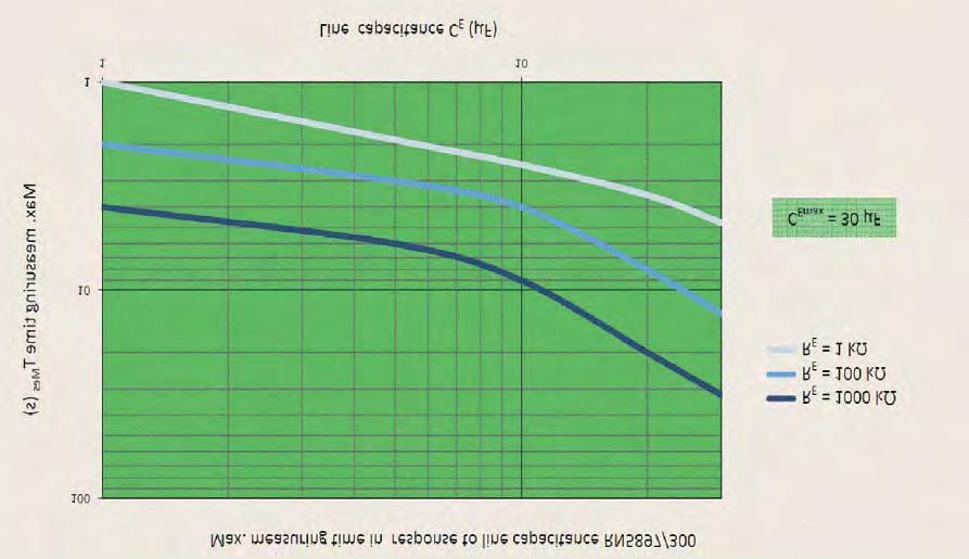
49 Characerisics M6 58
50 Monioring echnique VARIMETER IMD Insulaion monior LK Produc Descripion The insulaion monior LK 5896 of he varimeer IMD family provides bes and up o dae insulaion monioring of modern IT sysems in an opimum and sae of he ar way, fulfilling he relevan sandards. The device can be used in he mos flexible way for AC, DC and AC/DC sysems even wih large leakage capaciy o earh (PE). The adjusmen of he seing values is simple and user friendly done on 2 roary swiches on he fron of he device. Via LEDs he measured value, device parameers and device saus are indicaed easy o read. The uni has 3 relay conacs o signal Insulaion and device failures. The analogue oupu provides a volage and curren signal proporional o he acual insulaion resisance, which can be conneced o a superior conrol (plc), anoher sysem or exernal display uni. In addiion he LK 5896 provides a second measuring circui ha can be used o monior an inverer on he AC side also when he inverer is disconneced. Your Advanages Prevenive fire and sysem proecion Quick faul localisaion hrough selecive earh faul deecion o L+ and L- Universal applicaion in non-earhed AC, DC, AC/DC neworks wih up o 1000 V nominal volage Suiable for large leakage capaciances up o 3000 μf Simples seing via engaging roary swiches For monioring phoovolaic sysem, also wih hin-film echnology Opimised measuring imes - normally shorer han wih known mehods Monioring also wih volage-free mains Addiional measuring circui allows AC oupu monioring even wih he inverer swiched off, e.g. wih hybrid vehicles Measuring circui wih broken wire deecion No addiional coupling device required Trigger oupu for insulaion faul locaing sysem Analogue oupu for value of he insulaion resisance: V / ma ( V / ma) Feaures Insulaion monioring according o IEC/EN Deecion of symmeric and asymmeric insulaion fauls Measuring circuis can be disconneced via conrol erminals, e.g. for mains couplings 1 changeover conac each for prewarning and alarm 3. oupu relay for signalling wire break and device fauls Prewarning hreshold seing range: 20 kω... 2 MΩ Alarm hreshold seing range: 1 kω kω Energized or de-energized on rip can be seleced for oupu relay Seing he maximum leakage capaciance o shoren he response ime Simple, clearly arranged adjusmen of he device wih screwdriver LED chain o indicae he curren insulaion resisance Display of acive measuring circuis Auomaic and manual device self-es Alarm sorage selecable Exernal es and rese pushbuon can be conneced Widh: 90 mm Connecion Terminals Terminal designaion Signal designaion A1+, A2 DC-Auxiliary volage L(+), L(-) Connecion for main measuring circui U, V Connecion for auxiliary measuring circui KE, PE Connecion for proecive conducor Conrol inpu (manual/auo rese) G, R G/R no bridged: manual rese G/R bridged: auo rese Conrol inpu (Exernal es inpu) G, T connecion opion for exernal device es pushbuon Conrol inpu (main measuring circui deacivaion) G, HM G/HM no bridged: : Main measuring circui acivaed G/HM bridged: Main measuring circui deacivaed Conrol inpu (aux. measuring circui deacivaion) G, ZM G/ZM no bridged: aux. measuring circui deacivaed G/ZM bridged: aux. measuring circui acivaed Analogue oupu XA/GA no bridged: XA, GA, IA, UA UA-GA V; IA-GA mA XA/GA bridged: UA-GA V; IA-GA mA Alarm rigger oupu for insulaion faul Y1, Y2 locaing sysem, 12, 14 Alarm signal relay (1 changeover conac) 21, 22, 24 Prewarning signal relay (1 changeover conac) 31, 32, 34 Device faul signal relay (1 changeover conac) Approvals and Markings Applicaions Insulaion monioring of: Non-earhed AC, DC, AC/DC neworks UPS sysems Neworks wih frequency inverers Baery neworks Neworks wih direc curren drives Phoovolaic sysems Hybrid and baery-powered vehicles L (+) U U H ZM HM G AC/DC Circui Diagrams L (-) V T XA GA KE PE G R IA UA L+ L- U V PE KE PV 21 A A2 ERR Y1 Y2 M10832_b 59
51 Funcion Diagram Funcion alarm prewarning alarm prewarning R E earh faul R R VW AL auo rese open circui operaion closed circui operaion open circui operaion closed circui operaion -12 manual rese yellow LEDs VW red LEDs AL on off on off rese buon open circui operaion closed circui operaion yellow on LEDs VW off -14 open circui operaion closed circui operaion -12 red LEDs AL U H on off Flashing Codes LED "ERR" inernal device error connecion error U/V connecion error L+/L- connecion error PE/KE M082 M086 The device is supplied wih DC auxiliary volage via erminals A1+ / A2; a green "PWR" LED comes on. Swiching on he auxiliary volage is followed by an inernal self-es for 10 sec, where he LEDs of he indicaor sring ligh up in sequence. Afer his, measuremen of he insulaion resisance in he measuring circuis begins. Main measuring circui (Insulaion measuremen beween erminals L(+) / L(-) and PE / KE) Terminals L(+) and L(-) are conneced o he mains o be moniored. Broken wire deecion, consanly effecive during operaion, generaes an error messages if boh erminals are no conneced wih low resisance hrough he mains. In addiion, he wo erminals PE and KE mus be conneced o he proecive conducor sysem via separae lines. An error message is given here as well if a line is inerruped (see secion "Acions in case of connecion fauls"). If he main measuring circui is acivaed (erminal HM open), an acive measuring volage wih alernaing polariy is applied beween L(+) / L(-) and PE / KE o measure he insulaion resisance. During he measuring phase wih posiive polariy, he "HM" LED flashes wih a long On-phase and wih negaive polariy wih a shor On-phase. The "HM" LEDs goes off when he main measuring circui is swiched off hrough bridges of erminals HM-G. Measuremen is suspended and no more measuring volage reaches he measuring circui, so ha in case of coupling o a nework where anoher insulaion monior is already acive, no inerference can occur. The lengh of he posiive and negaive measuring phases depends on he seings on he roary swich "CE/μF", he acual leakage capaciance of he moniored nework and wih DC neworks, on he level and duraion of possible mains volage flucuaions. Correc and preferably quick measuremen is hus given wih differen mains condiions. In he even of paricularly adverse condiions and major inerferences, he measuring analysis can be seadied and delayed in addiion wih roary swich "v" if necessary. The curren insulaion resisance is deermined and analysed a he end of each measuring phase. The LED-chain and he analogue oupu show he resisance deermined, and he oupu relays for prewarning "VW" and alarm "AL" swich according o he respecive response values se. If he response hresholds have been undercu, he LEDs "VW" or "AL" ligh according o he insulaion faul locaion: "+", "-" or "+" and "-" simulaneously for AC fauls or symmeric insulaion fauls. Auxiliary measuring circui (Insulaion measuremen beween erminals U / V and PE / KE) The main measuring circui is conneced a he DC side for phoovolaic sysems and hybrid vehicles. The AC side is disconneced as long as he inverer is swiched off and can herefore no be moniored by he main measuring circui for insulaion fauls. However, i is useful o monior he AC side already before acivaing he inverer for insulaion fauls o PE for he inverer no o be even acivaed in he oupu circui in case of insulaion fauls. For his reason, he insulaion monior LK5896 is equipped wih an auxiliary measuring circui deermining he insulaion resisance of he AC side o PE / KE. To his end, erminals U and V are conneced o any phase preferred on he AC side. Broken wire deecion is effecive here as well and generaes an error message if erminals U / V are no conneced a low resisance, e.g. via load resisors, ransformer or moor windings. The auxiliary measuring circui is acivaed by bridging he device erminals ZM-G, for example, by he break conac of he (released) conacor ha acivaes he inverer. The "ZM" LED lighs when he auxiliary measuring circui is acivaed. The auxiliary measuring circuis moniors for he same response values as he main measuring circui. The curren insulaion resisance in he auxiliary measuring circui does no affec he analogue inpu bu is displayed a values < approx. 1.7 M on he LED-chain hrough corresponding LEDs, which are seleced here in flashing funcion o disinguish from he main measuring circui. The "ZM" LED flashes here a he same clock frequency. The LEDs of "VW" or "AL" flash if he respecively se response value is undercu only in he auxiliary measuring circui. 60
52 Funcion Soring insulaion faul message If erminal R is open, he insulaion faul messages from he main and auxiliary measuring circui are sored when he respecive response value is undercu, bu also when he insulaion resisance reurns o he OK-range. In addiion, he emporary minimum values of he insulaion resisance are indicaed on he LED-chain hrough dimmed LEDs. If he "Rese" buon on he device fron is pressed or erminal R is conneced wih G, he sored insulaion faul messages are rese when he insulaion resisance is again in he OK-range. Oupu relay for insulaion faul messages The roary swich "CE/μF Rel." allows selecing he operaing curren (A) or sandby curren (R) principle for he oupu relays "AL" (conacs ) and "VW" (conacs ). Wih he operaing curren principle, he relays respond when he response values are undercu, wih he sandby curren principle hey release when he response values are undercu. If 2 differen response values are no needed, "VW" and "AL" can be se o he same value. The oupu relays swich ogeher in his case. Analogue oupu The LK 5896 feaures a universal analogue oupu o display he curren insulaion resisance in he main measuring circui: Terminal UA-GA: V and erminal IA-GA: ma. By bridging erminals XA-GA, he oupu can be swiched o V and ma. Trigger oupu for insulaion faul locaing sysem This rigger oupu (Y1-Y2) can be coupled wih he rigger inpu Y1-Y2 of RR 5886 o iniiae auomaic faul locaion wih he insulaion faul locaing sysem, consising of RR 5886 and RR The rigger oupu is acivaed when he measuring value drops under he Alarm response value (AL). As long as i says under he response value or an alarm is sored, he rigger oupu Y1-Y2 remains acive. To preven insulaion monior LK 5896 from affecing insulaion faul locaing, RR 5886 generaes he deacivaion signal for LK 5896 a is erminals H-G. I is applied o erminals HM-G of LK 5896 and deacivaes is measuring circui. Broken wire deecion As menioned above, boh he main measuring circui and he auxiliary measuring circui are consanly moniored for wire breaks no only a Power-On or a manual or occasional auomaic es. The response ime of monioring is only a few seconds. Broken wire deecion beween L(+) and L(-) is performed via coupled alernaing volage. This alernaing volage is shor-circuied if he erminals are conneced o he conneced mains a low-resisance. The device deecs ha he mains o be moniored is properly conneced. Since his broken wire deecion is carried ou wih alernaing volage, large capaciances should be avoided beween L(+) and L(-), since he capaciive reacance of hese capaciances also shor-circuis his alernaing volage. The device would no longer deec a connecion faul on L(+)/L(-). Especially parallel lines should be prevened over larger disances. If larger capaciances beween L(+)/L(-) canno be avoided or if he coupled alernaing volage inerferes wih he sysem, version LK /101 (wihou broken wire deecion on L(+)/L(-) ) shall be used. Funcion The expanded es is sared when he inernal or exernal "Tes" buon is pressed (or is sill held) a he end of he 8 sec self-es, described above. The sequence is he same as wih he self-es (2 measuring phases a 4 sec + 2 sec pause); however, he oupu relays "AL" and "VW" as well as he associaed LEDs swich o he alarm sae and he analogue oupu proceeds o is lowes value. If he Rese buon is pressed during he 8 sec or erminals R-G are conneced, he expanded es is erminaed afer hese 8 sec. Oherwise, he phases of he expanded es are consanly repeaed, where, in addiion, he "ERR" LED and he faul signalling relay (conacs ) consanly receive curren. However, he expanded es is erminaed as soon as he Rese buon is pressed. The device swiches o he OK-sae and resars insulaion measuremen. Behaviour wih inernal device fauls If inernal device fauls were deeced during he es funcion, he "ERR" LED is li coninuously and he faul signalling relay ( ) responds. The main measuring circui is deacivaed inernally ("HM" LED goes off). The oupu relays "AL" and "VW" as well as he associaed LEDs swich o he alarm sae. The analogue oupu proceeds o is lowes value and all LEDs of he LED-chain exinguish. Behaviour wih connecion fauls IIf he auxiliary measuring circui is acivaed by bridging erminals ZM-G, broken wire deecion in he auxiliary measuring circui a U / V is signalled by he "ERR" LED flashing wih "Error code 1" and he faul signalling relay responds. Measuremen and analysis for he main measuring circui coninue normally. Measuremen is suspended if a line inerrupion is deeced a erminals L(+) / L(-); he "HM" LED goes off. The sae of he oupu relays "AL" / "VW" and associaed LEDs, he display of he LED-chain and he analogue oupu are "frozen". This Broken wire deecion is signalled by he "ERR" LED flashing wih "Error code 2" and he faul signalling relay responds. Measuremen of he connecion insulaion resisance resars afer he connecion inerrupion has been correced. However, sored alarm messages are preserved. If he connecions PE / KE o he proeciveconducor sysem are inerruped, he same responses ake place as wih an inerrupion a erminals L(+) / L(-), only ha he "ERR" LED indicaes "Error code 3". Device es funcions Principally, 2 differen es funcions are implemened: The "self-es" and he "expanded es": The self-es of he device is performed auomaically afer Power-On and every 4 operaing hours. I can also be riggered manually a any ime by pressing he "Tes" buon a he device fron or wih an exernal pushbuon conneced beween erminals T and G. Wih he self-es, conrary o he expanded es, he saus of he oupu relays and he analogue oupu are no affeced; he sequence is as follows: Swiching o he negaive measuring phase is performed for 4 sec. The "HM" LED flashes here wih a brief On-phase. The LEDs of he LED-chain are seleced in sequence and he inernal circui is checked. Afer his, swiching o he posiive measuring phase is performed for 4 sec. The "HM" LED flashes here wih a long On-phase. The LED-chain cycles again and addiional inernal ess are performed. Insulaion measuremen coninues normally afer a pause of 2 sec if no fauls have occurred. 61
53 Indicaors green LED PWR : on when auxiliary supply conneced red LED ERR : permanen on: a sysem error flashing: a connecion failure green LED HM : flashing: a acive main measuring cirui, ON-OFF-raio per measuremen phase: long ON period during measuremen phase wih posiiv polariy shor ON period during measuremen phase wih negaive polariy green LED ZM : permanen on: a acive auxiliary measuring circui, flashing: ar RE < 2 MΩ yellow LED-chain: 8 LEDs indicae he acual insulaing resisance ( 10 kω... 2 MΩ) flashing: for auxiliary measuring circui yellow LED VW + : permanen on: RE lower hen prewarning value o + poenial flashing: for auxiliary measuring circui yellow LED VW - : permanen on: RE lower hen prewarning value o - poenial flashing: for auxiliary measuring circui yellow LEDs VW + and VW - simulaneiy: permanen on: AC-faul / symmeric faul flashing: for auxiliary measuring circui red LED AL + : permanen on: RE lower hen ripping value o + poenial flashing: for auxiliary measuring circui red LED AL - : permanen on: RE lower hen ripping value o - poenial flashing: for auxiliary measuring circui red LEDs AL + And AL - simulaneiy: permanen on: AC-faul / symmeric faul flashing: for auxiliary measuring circui Noes Device erminals PE and KE mus always be conneced via separae lines o differen erminal poins of he proecive-conducor sysem. The main measuring circui can be conneced wih is erminals L(+) and L(-) boh o he DC and also AC side of a mixed nework; i is done mos pracically where he primary incoming power supply akes place. Selecor swich "v / UN" should be se accordingly. For phoovolaic sysems and hybrid vehicles, he main measuring circui of he LK 5896 is conneced on he DC side; he auxiliary measuring circui can hen be used o monior he (deacivaed) AC side. For he main measuring circui, he nominal volage range for DC is specified wih 1000 V; however, absolue values up o max. DC 1500 V are permissible. Only one insulaion monior may be acive in a nework o be moniored, since he devices would oherwise influence each oher. When coupling several neworks or incoming feed secions, where each of hem is equipped wih is own insulaion monior, all of hem mus be deacivaed excep for one insulaion monior. Such deacivaion can be beneficially handled via he HM-G conrol erminals wih he LK The main measuring circui is designed for large leakage capaciances up o 3000 μf. The selecion swich "CE/μF" mus be se accordingly. Measuremen of he insulaion resisances is no falsified by his; however, longer periods are required for he measuring phases han wih small capaciances. If he maximum approximae leakage capaciance is known, he selecor swich "CE/μF" can possibly be se o smaller values, which reduces he response ime furher. The measuring circui should no be conneced via longer parallel guided wires, as his may inerfere wih he broken wire deecion. Also large capaciies beween L(+) und L(-) have o be avoided. No exernal poenials may be conneced o conrol erminals "ZM", "HM", "T" and "R". The associaed reference poenial is "G" (idenical wih PE), and he connecion of he erminals is made via bridges o "G". The analogue oupu and rigger oupu Y1-Y2 are elecrically separaed from he res of he circuiry. The rigger oupu is inended for connecion o he DOLD insulaion faul locaor sysem, consising of RR 5886 and RR No exernal volages may be applied. Aenion!! The device mus no be operaed wihou KE/PE connecion. Before making insulaion and volage ess, he monior LK 5896 has o be disconneced.! The volage of he moniored volage sysem is conneced o erminals L(+) / L(-). Please observe sufficien disance o erminals of neighbour devices and o he grounded meal cabine or box (min 0.5 cm). WARNING The device moniors HIGH-VOLTAGE Cauion High-Volage when working on he device! Disconnec all power supplies before servicing equipmen! 62
54 Technical Daa Main measuring cirui L(+) / L(-) o PE / KE Nominal volage U N : DC V; AC V Volage range: DC max V; AC max. 00 V Frequency range: DC or Hz Max. line capaciance: 3000 μf Inernal resisance (AC / DC): > 280 kω Measuring volage: approx. ± 95 V Max. mesured curren (R E = 0): < 0.35 ma Auxiliary measuring circui U / V o PE / KE Nominal volage U N : AC V Volage range: U N Frequency range: Hz Max. line capaciance: 10 μf Inernal resisance (AC / DC): approx. 2 MΩ Measuring volage: approx. 12 V Max. mesured curren (R E = 0): approx. 6 μa Response values R E Pre-warning ( VW ): kω: Alarm ( AL ) kω: each adjusable via roaional swiches Response inaccuracy: ± 15 % kω IEC Schalpunk-Hyserese a range 10 kω kω: approx. 25 % ou of range: On delay a C E = 1μF, approx. 40 % kω R E of o 0,5 * response value: < 10 s Measuring ime: siehe Kennlinie Inpu auxiliary volage DC-Inpu (A1+ /A2) Nominal volage U H : Volage range: Nominal consumpion: DC 24 V DC V max. 5 W Conrol inpu (beween ZM, HM, T, R and G) Curren flow: No-load volage o G: Permissible wire lengh: Min. acivaion ime: Oupu approx. 3 ma approx. 12 V < 50 m 0.5 s Conacs: 3 x 1 changeover conacs for VW, AL and ERR Thermal curren I h : 4 A Swiching capaciy o AC 15: NO conac: 3 A / AC 230 V IEC/EN NC conac: 1 A / AC 230 V IEC/EN Elecrical life a 8 A, AC 250 V: 1 x 10 4 swiching cycles Shor circui srengh max. fuse raing: 4 A gl IEC/EN Mechanical life: 10 x 10 6 swiching cycles Analogue oupu for acual insulaing value, galvanic separaion Terminals IA(+) / GA: ma (bridge XA-GA: ma); max. burden 500 Ω Terminals UA(+) / GA: V (bridge XA GA: V); max. curren 10 ma Scaling lower analogue value: R E = 0; upper analogue value: R E = Middle of range: R E = 289 kω Formula example for 0-10V: RE = 289 kω / (10V / UA 1) for 2-10V: RE = 289 kω / (8V / (UA-2V) 1) Technical Daa General Daa Operaing mode: Temperaure range Operaion: Coninuous operaion C (device mouned away from hea generaion componens) C (device mouned wihou disance heaed by devices wih same load) Sorage: C Relaive air humidiy: 93 % bei 40 C Amospheric pressure: mbar ( kpa) Aliude: < m IEC Clearance and creepage disances raed impulse volage / polluion degree IEC Main measuring cirui L(+) / L(-) o auxiliary volage DC and relay conacs VW, AL, ERR and analogue oupu IA, UA, GA and rigger oupu Y1-Y2: 8 kv / 2 auxiliary measuring circui U / V o auxiliary volage DC and relay conacs VW, AL, ERR and analogue oupu IA, UA, GA and rigger oupu Y1-Y2: 8 kv / 2 auxiliary volage DC and rigger oupu Y1-Y2 o relay conacs VW, AL, ERR and analogue oupu IA, UA, GA: 8 kv / 2 relay conac VW o relay conac AL o relay conac ERR: 4 kv / 2 analogue oupu IA, UA, GA o relay conacs VW, AL, ERR and rigger oupu Y1-Y2: 4 kv / 2 rigger oupu Y1-Y2 o relay conacs VW, AL, ERR: 4 kv / 2 Insulaion es volage Rouine es: AC 5 kv; 1 s AC 2,5 kv; 1 s EMC Elecrosaic discharge (ESD): 8 kv (air) IEC / EN HF irradiaion: 80 MHz GHz: 10 V / m IEC / EN Fas ransiens: 4 kv IEC / EN Surge volages beween A1 - A2: 1 kv IEC/EN beween L(+) - L(-): 2 kv IEC/EN beween A1, A2 - PE and L(+), L(-) - PE: 4 kv IEC/EN beween conrol line: 0,5 kv IEC/EN beween conrol line and earh: 1 kv IEC/EN HF-wire guided 10V IEC / EN Inerference suppression: Limi value class A* ) * ) The device is designed for he usage under indusrial condiions (Class A, EN 550). When conneced o a low volage public sysem (Class B, EN 550) radio inerference can be generaed. To avoid his, appropriae measures have o be aken. Degree of proecion Housing: IP 40 IEC/EN Terminals: IP 20 IEC/EN Housing: Thermpolasic wih V0 behaviour according o UL subjec 94 Vibraion resisance: IEC/EN Ampliude 0.35 mm frequency Hz Ampliude ± 1mm, frequency Hz Hz, acceleraion ± 0.7 g n Shock resisance: 10 g n / ms, 3 pulses IEC/EN Climae resisance: 25 / 060 / 04 IEC/EN Terminal designaion: EN
 DIN 46228-1/-2/-3 Insulaion of wires or sleeve lengh: 8 mm Wire fixing: Plus-minus erminal screws M3,5 erminal wih wire proecion Fixing orque: 0.")
55 Technical Daa Wire connecion DIN /-2/-3/-4 Screw erminals (fixed): 1 x 4 mm 2 solid or 1 x 2,5 mm 2 sranded ferruled (isolaed) or 2 x 1,5 mm 2 sranded ferruled (isolaed) DIN /-2/-3-4 or 2 x 2,5 mm 2 sranded ferruled (isolaed) DIN /-2/-3 Insulaion of wires or sleeve lengh: 8 mm Wire fixing: Plus-minus erminal screws M3,5 erminal wih wire proecion Fixing orque: 0.8 Nm Mouning: DIN rail IEC / EN Weigh: approx. 584 g Dimensions Connecion Examples L+ L- PE L(+) R L(-) G ZM G, 12, 14: AL 21, 22, 24: VW 31, 32, 34: ERR T HM *) PE KE U LK5896 A1+ Rese Tes Power supply V A2 DC Analog Oupu IA UA XA GA 0/2-10V 0/4-20mA M10834_b Widh x heigh x deph: 90 x 90 x 121 mm *)G-HM conneced: Measuring circui is off Insulaion monioring DC-side Sandard Type LK /100 DC V Aricle number: Oupus: 1 changeover conac for pre-warning 1 changeover conac for alarm 1 changeover conac for connecion- / sysem error Auxiliary measuring circui for inverer oupu Auxiliary volage: DC V Seing range pre-warning: 20 kω... 2 MΩ Seing range alarm: 1 kω kω Adjusable line capaciance Open- / or closed circui operaion Adjusable ime delay / selecion of AC or DC connecion Analogue oupu: ma / ma; V / V Trigger oupu for insulaion faul locaing sysem Widh: 90 mm 3 L2 L3 PE L(+) L(-) G HM *) PE LK5896 *)G-HM conneced: Measuring circui is off Insulaion monioring AC-side KE M10835 Varian LK /101: wihou wire-break deecion a L(+)/L(-) Accessories EH 5861/005: Indicaing insrumen, degree of proecion: IP 52 Aricle number: The indicaing device EH 5861 is exernally conneced o he insulaion monior on erminals UA / GA (0-10 V) and shows he acual insulaion resisance of he volage sysem o ground. Dimensions: Widh x heigh x deph 96 x 96 x 52 mm 64
56 Characerisics Analog oupu curren IA in response o insulaion resisance R E Insulaion resisance R E (kω) ma 4-20 ma Analog oupu curren IA (ma) Max. measuring ime in response o line capaciance Max. measuring ime T An (s) R E = 2000 kω R E = 100 kω R E = 1 kω Line capaciance C E (μf) M295 65
57 Monioring echnique VARIMETER IMD Insulaion monior LK Your Advanages Prevenive fire and sysem proecion Quick faul localisaion hrough selecive earh faul deecion o L+ and L- Universal applicaion in non-earhed AC, DC, AC/DC neworks wih up o 1000 V nominal volage Suiable for large leakage capaciances up o 3000 μf Simples seing via engaging roary swiches For monioring phoovolaic sysem, also wih hin-film echnology Opimised measuring imes normally shorer han wih known mehods Monioring also wih volage-free mains Measuring circui wih broken wire deecion No addiional coupling device required Produc Descripion The insulaion monior LK 5895 of he varimeer IMD family provides bes and up o dae insulaion monioring of modern IT sysems in an opimum and sae of he ar way fulfilling he relevan sandards. The device can be used in he mos flexible way for AC, DC and AC/DC sysems even wih large leakage capaciy o earh (PE). The adjusmen of he seing values is simple and user friendly done on 2 roary swiches on he fron of he device. Via LEDs he measured value, device parameers and device saus are indicaed easy o read. Circui Diagram L (+) G KE HM PE G G L (-) U H T R Connecion Terminals L+ L PE KE 21 A1 + A2 M10839_a Terminal designaion Signal designaion A1+, A2 DC-Auxiliary volage L(+), L(-) Connecion for measuring cirui KE, PE Connecion for proecive conducor Conrol inpu (manual/auo rese) G, R G/R no bridged: manual rese G/R bridged: auo rese Conrol inpu (Exernal es inpu) G, T connecion opion for exernal device es pushbuon Conrol inpu (measuring circui deacivaion) G, HM G/HM no bridged: measuring circui acivaed G/HM bridged: measuring circui deacivaed, 12, 14 Alarm signal relay (1 changeover conac) 21, 22, 24 Prewarning signal relay (1 changeover conac) Feaures Insulaion monioring according o IEC/EN Deecion of symmeric and asymmeric insulaion fauls Measuring circuis can be disconneced via conrol erminals, e.g. for mains couplings 1 changeover conac each for prewarning and alarm Prewarning hreshold seing range: 20 kω... 2 MΩ Alarm hreshold seing range: 1 kω kω Energized or de-energized on rip can be seleced for oupu relay Seing he maximum leakage capaciance o shoren he response ime Simple, clearly arranged adjusmen of he device wih screwdriver LED chain o indicae he curren insulaion resisance Display of acive measuring circuis Auomaic and manual device self-es Alarm sorage selecable Exernal es and rese pushbuon can be conneced Widh 90 mm Approvals and Markings Applicaions AC/DC PV Insulaion monioring of: Non-earhed AC, DC, AC/DC neworks UPS sysems Neworks wih frequency inverers Baery neworks Neworks wih direc curren drives Phoovolaic sysems Hybrid and baery-powered vehicles 66
58 Funcion Diagram Funcion alarm prewarning alarm prewarning auo rese open circui operaion closed circui operaion open circui operaion closed circui operaion -12 manual rese yellow LEDs VW red LEDs AL R E earh faul R R VW AL on off on off rese buon open circui operaion closed circui operaion yellow on LEDs VW off -14 open circui operaion closed circui operaion -12 red LEDs AL U H on off M082 If he device is supplied wih DC auxiliary volage, he a green "PWR" LED comes on. Swiching on he auxiliary volage is followed by an inernal selfes for 10 sec, where he LEDs of he indicaor sring ligh up in sequence. Afer his, measuremen of he insulaion resisance in he measuring circuis begins. Measuring circui (Insulaion measuremen beween erminals L(+) / L(-) and PE / KE) Terminals L(+) and L(-) are conneced o he mains o be moniored. Broken wire deecion, consanly effecive during operaion, generaes an error messages if boh erminals are no conneced wih low resisance hrough he mains. In addiion, he wo erminals PE and KE mus be conneced o he proecive conducor sysem via separae lines. An error message is given here as well if a line is inerruped (see secion "Acions in case of connecion fauls"). If he main measuring circui is acivaed (erminal HM open), an acive measuring volage wih alernaing polariy is applied beween L(+) / L(-) and PE / KE o measure he insulaion resisance. During he measuring phase wih posiive polariy, he "HM" LED flashes wih a long On-phase and wih negaive polariy wih a shor On-phase. The "HM" LEDs goes off when he main measuring circui is swiched off hrough bridges of erminals HM-G. Measuremen is suspended and no more measuring volage reaches he measuring circui, so ha in case of coupling o a nework where anoher insulaion monior is already acive, no inerference can occur. The lengh of he posiive and negaive measuring phases depends on he seings on he roary swich "CE/μF", he acual leakage capaciance of he moniored nework and wih DC neworks, on he level and duraion of possible mains volage flucuaions. Correc and preferably quick measuremen is hus given wih differen mains condiions. In he even of paricularly adverse condiions and major inerferences, he measuring analysis can be seadied and delayed in addiion wih roary swich "v" if necessary. The curren insulaion resisance is deermined and analysed a he end of each measuring phase. The LED-chain show he resisance deermined, and he oupu relays for prewarning "VW" and alarm "AL" swich according o he respecive response values se. If he response hresholds have been undercu, he LEDs "VW" or "AL" ligh according o he insulaion faul locaion: "+", "-" or "+" and "-" simulaneously for AC fauls or symmeric insulaion fauls. Soring insulaion faul message If erminal R is open, he insulaion faul messages (relay, LEDs) are sored when he respecive response value is undercu, bu also when he insulaion resisance reurns o he OK-range. In addiion, he emporary minimum values of he insulaion resisance are indicaed on he LEDchain hrough dimmed LEDs. If he "Rese" buon on he device fron is pressed or erminal R is conneced wih G, he sored insulaion faul messages are rese when he insulaion resisance is again in he OK-range. Flashing Codes LED "ERR" inernal device error connecion error L+/L- connecion error PE/KE M084 Oupu relay for insulaion faul messages The roary swich "CE/μF Rel." allows selecing he open circui (A) or closed circui (R) operaion for he oupu relays "AL" (conacs ) and "VW" (conacs ). Wih he open circui operaion, he relays respond when he response values are undercu, wih he closed circui operaion hey release when he response values are undercu. If 2 differen response values are no needed, "VW" and "AL" can be se o he same value. The oupu relays swich ogeher in his case ( 2u ). Broken wire deecion As menioned above, all erminals of he measuring circui are consanly moniored for wire breaks - no only a Power-On or a manual or occasional auomaic es. The response ime of monioring is only a few seconds. Broken wire deecion beween L(+) and L(-) is performed via coupled alernaing volage. This alernaing volage is shor-circuied if he erminals are conneced o he conneced mains a low-resisance. The device deecs ha he mains o be moniored is properly conneced. Since his broken wire deecion is carried ou wih alernaing volage, large capaciances should be avoided beween L(+) and L(-), since he capaciive reacance of hese capaciances also shor-circuis his alernaing volage. The device would no longer deec a connecion faul on L(+)/L(-). Especially parallel lines should be prevened over larger disances. If larger capaciances beween L(+)/L(-) canno be avoided or if he coupled alernaing volage inerferes wih he sysem, version LK /0 (wihou broken wire deecion on L(+)/L(-) ) shall be used. 67
59 Funcion Device es funcions Principally, 2 differen es funcions are implemened: The "self-es" and he "expanded es": The self-es of he device is performed auomaically afer Power-On and every 4 operaing hours. I can also be riggered manually a any ime by pressing he "Tes" buon a he device fron or wih an exernal pushbuon conneced beween erminals T and G. Wih he self-es, conrary o he expanded es, he saus of he oupu relays and he analogue oupu are no affeced; he sequence is as follows: Swiching o he negaive measuring phase is performed for 4 sec. The "HM" LED flashes here wih a brief On-phase. The LEDs of he LED-chain are seleced in sequence and he inernal circui is checked. Afer his, swiching o he posiive measuring phase is performed for 4 sec. The "HM" LED flashes here wih a long On-phase. The LED-chain cycles again and addiional inernal ess are performed. Insulaion measuremen coninues normally afer a pause of 2 sec if no fauls have occurred. The expanded es is sared when he inernal or exernal "Tes" buon is pressed (or is sill held) a he end of he 8 sec self-es, described above. The sequence is he same as wih he self-es (2 measuring phases a 4 sec + 2 sec pause); however, he oupu relays "AL" and "VW" as well as he associaed LEDs swich o he alarm sae and he analogue oupu proceeds o is lowes value. If he Rese buon is pressed during he 8 sec or erminals R-G are conneced, he expanded es is erminaed afer hese 8 sec. Oherwise, he phases of he expanded es are consanly repeaed, where, in addiion, he "ERR" LED is on. However, he expanded es is erminaed as soon as he Rese buon is pressed. The device swiches o he OK-sae and resars insulaion measuremen. Behaviour wih inernal device fauls If inernal device fauls were deeced during he es funcion, he "ERR" LED is li coninuously and he measuring circui is deacivaed inernally ("HM" LED goes off). The oupu relays "AL" and "VW" as well as he associaed LEDs swich o he alarm sae and all LEDs of he LED-chain exinguish. Behaviour in he case of connecion fauls If broken wire is deeced on erminals L(+) / L(-), he measuremen is inerruped and he LED "HM" goes off. This connecion failure is indicaed by LED "ERR" wih "failure code 2". The oupu relays "AL" and "VW" as well as he corresponding LEDs go ino alarm sae and all LEDs of he indicaor LED chain go off. Afer removing he he inerrupion he measuremen of he insulaion resisance sars again. Sored alarm saes remain acive. When inerruping he connecion PE / KE o he proecive ground, he uni reacs in he same way as wih an inerrupion on L(+) / L(-), only he LED "ERR" shows "failure code 3". Indicaors green LED PWR : on when auxiliary supply conneced red LED ERR : permanen on: a sysem error flashing: a connecion failure green LED HM : flashing: a acive main measuring cirui, ON-OFF-raio per measuremen phase: long ON period during measuremen phase wih posiiv polariy shor ON period during measuremen phase wih negaive polariy Noes Device erminals PE and KE mus always be conneced via separae lines o differen erminal poins of he proecive-conducor sysem. The measuring circui can be conneced wih is erminals L(+) and L(-) boh o he DC and also AC side of a mixed nework; i is done mos pracically where he primary incoming power supply akes place. Selecor swich "v / U N " should be se accordingly. For phoovolaic sysems and hybrid vehicles, he measuring circui of he LK 5895 is conneced on he DC side; he auxiliary measuring circui can hen be used o monior he (deacivaed) AC side. For he main measuring circui, he nominal volage range for DC is specified wih 1000 V; however, absolue values up o max. DC 1500 V are permissible. Only one insulaion monior may be acive in a nework o be moniored, since he devices would oherwise influence each oher. When coupling several neworks or incoming feed secions, where each of hem is equipped wih is own insulaion monior, all of hem mus be deacivaed excep for one insulaion monior. Such deacivaion can be beneficially handled via he HM-G conrol erminals wih he LK The measuring circui is designed for large leakage capaciances up o 3000 μf. The selecion swich "CE/μF" mus be se accordingly. Measuremen of he insulaion resisances is no falsified by his; however, longer periods are required for he measuring phases han wih small capaciances. If he maximum approximae leakage capaciance is known, he selecor swich "CE/μF" can possibly be se o smaller values, which reduces he response ime furher. The measuring circui should no be conneced via longer parallel guided wires, as his may inerfere wih he broken wire deecion. Also large capaciies beween L(+) und L(-) have o be avoided. No exernal poenials may be conneced o conrol erminals, "HM", "T" and "R". The associaed reference poenial is "G" (idenical wih PE), and he connecion of he erminals is made via bridges o "G". Aenion!! WARNING The device mus no be operaed wihou KE/PE connecion. Before making insulaion and volage ess, he monior LK 5895 has o be disconneced.! The volage of he moniored volage sysem is conneced o erminals L(+) / L(-). Please observe sufficien disance o erminals of neighbour devices and o he grounded meal cabine or box (min 0.5 cm). The device moniors HIGH-VOLTAGE Cauion High-Volage when working on he device! Disconnec all power supplies before servicing equipmen! yellow LED-chain: 8 LEDs indicae he acual insulaing resisance ( 10 kω... 2 MΩ) gyellow LED VW + : permanen on: R E lower hen prewarning value o + poenial yellow LED VW - : permanen on: R E lower hen prewarning value o - poenial yellow LEDs VW + and VW - simulaneiy: permanen on: AC-faul / symmeric faul red LED AL + : permanen on: R E lower hen ripping value o + poenial ed LED AL - : permanen on: R E lower hen ripping value o - poenial red LEDs AL + und AL - simulaneiy: permanen on: AC-faul / symmeric faul 68
60 Technical Daa Measuring cirui L(+) / L(-) o PE / KE Nominal volage U N : DC V; AC V Volage range: DC max V; AC max. 00 V Frequency range: DC or Hz Max. line capaciance: 3000 μf Inernal resisance (AC / DC): > 280 kω Measuring volage: approx. ± 95 V Max. mesured curren (R E = 0): < 0.35 ma Response values R E Pre-warning ( VW ): kω: Alarm ( AL ) kω: each adjusable via roaional swiches Response inaccuracy: ± 15 % kω IEC Response value hyseresis a range 10 kω kω: approx. 25 % ou of range: approx. 40 % kω On delay a C E = 1μF, R E of o 0,5 * response value: < 10 s Inpu auxiliary volage DC-Inpu (A1+ /A2) Nominal volage U H : Volage range: Nominal consumpion: DC 24 V DC V max. 5 W Conrol inpu (beween HM, T, R and G) Curren flow: No-load volage o G: Permissible wire lengh: Min. acivaion ime: Oupu approx. 3 ma approx. 12 V < 50 m 0.5 s Conacs: 2 x 1 changeover conacs for VW and AL Thermal curren I h : 4 A Swiching capaciy o AC 15: NO conac: 3 A / AC 230 V IEC/EN NC conac: 1 A / AC 230 V IEC/EN Elecrical life a 8 A, AC 250 V: 1 x 10 4 swiching cycles Shor circui srengh max. fuse raing: 4 A gl IEC/EN Mechanical life: 10 x 10 6 swiching cycles General Daa Operaing mode: Temperaure range Operaion: Coninuous operaion C (device mouned away from hea generaion componens) C (device mouned wihou disance heaed by devices wih same load) Sorage: C Relaive air humidiy: 93 % bei 40 C Amospheric pressure: mbar ( kpa) Aliude: < m IEC Clearance and creepage disances raed impulse volage / polluion degree IEC Measuring cirui L(+) / L(-) o auxiliary volage DC und relay conacs VW, AL: 8 kv / 2 auxiliary volage DC o relay conacs VW, AL: 8 kv / 2 relay conacs VW o relay conac AL: 4 kv / 2 Insulaion es volage Rouine es: AC 5 kv; 1 s AC 2,5 kv; 1 s Technical Daa EMC Elecrosaic discharge (ESD): 8 kv (air) IEC / EN HF irradiaion: 80 MHz GHz: 10 V / m IEC / EN Fas ransiens: 4 kv IEC / EN Surge volages beween A1 - A2: 1 kv IEC/EN beween L(+) - L(-): 2 kv IEC/EN beween A1, A2 - PE and L(+), L(-) - PE: 4 kv IEC/EN beween conrol line: 0,5 kv IEC/EN beween conrol line and earh: 1 kv IEC/EN HF-wire guided 10V IEC / EN Inerference suppression: Limi value class A* ) * ) The device is designed for he usage under indusrial condiions (Class A, EN 550). When conneced o a low volage public sysem (Class B, EN 550) radio inerference can be generaed. To avoid his, appropriae measures have o be aken. Degree of proecion Housing: IP 40 IEC/EN Terminals: IP 20 IEC/EN Housing: Thermpolasic wih V0 behaviour according o UL subjec 94 Vibraion resisance: IEC/EN Ampliude 0.35 mm frequency Hz Ampliude ± 1mm, frequency Hz Hz, acceleraion ± 0.7 g n Shock resisance: 10 g n / ms, 3 pulses IEC/EN Climae resisance: 25 / 060 / 04 IEC/EN Terminal designaion: EN Wire connecion DIN /-2/-3/-4 Screw erminals (fixed): 1 x 4 mm 2 solid or 1 x 2,5 mm 2 sranded ferruled (isolaed) or 2 x 1,5 mm 2 sranded ferruled (isolaed) DIN /-2/-3-4 or 2 x 2,5 mm 2 sranded ferruled (isolaed) DIN /-2/-3 Insulaion of wires or sleeve lengh: 8 mm Wire fixing: Plus-minus erminal screws M3,5 erminal wih wire proecion Fixing orque: 0.8 Nm Mouning: DIN rail IEC / EN Weigh: approx. 500 g Dimensions Widh x heigh x deph: Sandard Type 90 x 90 x 121 mm LK /010 DC V Aricle number: Oupus: 1 changeover conac for pre-warning 1 changeover conac for alarm Auxiliary volage: DC V Seing range pre-warning: 20 kω... 2 MΩ Seing range alarm: 1 kω kω Adjusable line capaciance Open- / or closed circui operaion Widh: 90 mm Varian LK /0: wihou wire-break deecion a L(+)/L(-) 69
61 Connecion Examples L+ L- PE 3 L2 L3 PE L(+) L(-) G HM *) PE KE L(+) L(-) G *) HM PE KE, 12, 14: AL 21, 22, 24: VW LK5895 LK5895 R G T A1+ A2 DC Rese Tes Power supply M10841_a *)G-HM conneced: Measuring circui is off M10842 *)G-HM conneced:measuring circui is off Insulaion monioring DC-side Insulaion monioring AC-side Characerisic Max. measuring ime in response o line capaciance Max. measuring ime T An (s) R E = 2000 kω R E = 100 kω R E = 1 kω Line capaciance C E (μf) M295 70

62 Monioring echnique VARIMETER IMD Insulaion monior LK Your Advanages Prevenive fire and sysem proecion Quick faul localisaion hrough selecive earh faul deecion o L+ and L- Universal applicaion in non-earhed AC, DC, AC/DC neworks wih up o 690 V nominal volage Suiable for large leakage capaciances up o 1000 μf Simples seing via engaging roary swiches Opimised measuring imes - normally shorer han wih known mehods Monioring also wih volage-free mains Measuring circui wih broken wire deecion No addiional coupling device required Produc Descripion The insulaion monior LK 5894 of he varimeer IMD family provides bes and up o dae insulaion monioring of modern IT sysems in an opimum and sae of he ar way fulfilling he relevan sandards. The device can be used in he mos flexible way for AC, DC and AC/DC sysems even wih large leakage capaciy o earh (PE). The adjusmen of he seing values is simple and user friendly done on 2 roary swiches on he fron of he device. Via LEDs he measured value, device parameers and device saus are indicaed easy o read. Circui Diagram Feaures Insulaion monioring according o IEC/EN Deecion of symmeric and asymmeric insulaion fauls 2 changeover conacs Prewarning hreshold seing range: 20 kω... 2 MΩ Alarm hreshold seing range: 1 kω kω Energized or de-energized on rip can be seleced for oupu relay Seing he maximum leakage capaciance o shoren he response ime Simple, clearly arranged adjusmen of he device wih screwdriver LED chain o indicae he curren insulaion resisance Display of acive measuring circuis Auomaic and manual device self-es Widh: 90 mm Approvals and Markings L (+) L (-) AC/DC L+ L U H Applicaions KE PE G G T R PE KE 21 A1 + A2 M10942 Insulaion monioring of: Non-earhed AC, DC, AC/DC neworks UPS sysems Neworks wih frequency inverers Baery neworks Neworks wih direc curren drives Hybrid and baery-powered vehicles Connecion Terminals Terminal designaion Signal designaion A1+, A2 DC-Auxiliary volage L(+), L(-) Connecion for measuring cirui KE, PE Connecion for proecive conducor Conrol inpu (manual/auo rese) G, R G/R no bridged: manual rese G/R bridged: auo rese Conrol inpu (Exernal es inpu) G, T connecion opion for exernal device es pushbuon, 12, 14 Alarm signal relay (1 changeover conac) 21, 22, 24 Prewarning signal relay (1 changeover conac) 71
63 Funcion Diagram Funcion alarm prewarning alarm prewarning R E earh faul R R VW AL auo rese open circui operaion closed circui operaion open circui operaion closed circui operaion -12 manual rese yellow LEDs VW red LEDs AL on off on off rese buon open circui operaion closed circui operaion yellow on LEDs VW off -14 open circui operaion closed circui operaion -12 red LEDs AL U H on off Flashing Codes LED "ERR" M082 If he device is supplied wih DC auxiliary volage, he a green "PWR" LED comes on. Swiching on he auxiliary volage is followed by an inernal selfes for 10 sec, where he LEDs of he indicaor sring ligh up in sequence. Afer his, measuremen of he insulaion resisance in he measuring circuis begins. Measuring circui (Insulaion measuremen beween erminals L(+) / L(-) and PE / KE) Terminals L(+) and L(-) are conneced o he mains o be moniored. Broken wire deecion, consanly effecive during operaion, generaes an error messages if boh erminals are no conneced wih low resisance hrough he mains. In addiion, he wo erminals PE and KE mus be conneced o he proecive conducor sysem via separae lines. An error message is given here as well if a line is inerruped (see secion "Acions in case of connecion fauls"). If he main measuring circui is acivaed, an acive measuring volage wih alernaing polariy is applied beween L(+) / L(-) and PE / KE o measure he insulaion resisance. During he measuring phase wih posiive polariy, he "Acive" LED flashes wih a long On-phase and wih negaive polariy wih a shor On-phase. The lengh of he posiive and negaive measuring phases depends on he seings on he roary swich "CE/μF", he acual leakage capaciance of he moniored nework and wih DC neworks, on he level and duraion of possible mains volage flucuaions. Correc and preferably quick measuremen is hus given wih differen mains condiions. In he even of paricularly adverse condiions and major inerferences, he measuring analysis can be seadied and delayed in addiion wih roary swich "v" if necessary. The curren insulaion resisance is deermined and analysed a he end of each measuring phase. The LED chain show he resisance deermined, and he oupu relays for prewarning "VW" and alarm "AL" swich according o he respecive response values se. If he response hresholds have been undercu, he LEDs "VW" or "AL" ligh according o he insulaion faul locaion: "+", "-" or "+" and "-" simulaneously for AC fauls or symmeric insulaion fauls. Soring insulaion faul message If erminal R is open, he insulaion faul messages from he main and auxiliary measuring circui are sored when he respecive response value is undercu, bu also when he insulaion resisance reurns o he OK-range. In addiion, he emporary minimum values of he insulaion resisance are indicaed on he LED chain hrough dimmed LEDs. If he "Rese" buon on he device fron is pressed or erminal R is conneced wih G, he sored insulaion faul messages are rese when he insulaion resisance is again in he OK-range. Oupu relay for insulaion faul messages The roary swich "CE/μF Rel." allows selecing he operaing curren (A) or sandby curren (R) principle for he oupu relays "AL" (conacs ) and "VW" (conacs ). Wih he operaing curren principle, he relays respond when he response values are undercu, wih he sandby curren principle hey release when he response values are undercu. If 2 differen response values are no needed, "VW" and "AL" can be se o he same value. The oupu relays swich ogeher in his case. inernal device error connecion error L+/L- connecion error PE/KE M084 Broken wire deecion As menioned above, boh he main measuring circui and he auxiliary measuring circui are consanly moniored for wire breaks - no only a Power-On or a manual or occasional auomaic es. The response ime of monioring is only a few seconds. Broken wire deecion beween L(+) and L(-) is performed via coupled alernaing volage. This alernaing volage is shor-circuied if he erminals are conneced o he conneced mains a low-resisance. The device deecs ha he mains o be moniored is properly conneced. Since his broken wire deecion is carried ou wih alernaing volage, large capaciances should be avoided beween L(+) and L(-), since he capaciive reacance of hese capaciances also shor-circuis his alernaing volage. The device would no longer deec a connecion faul on L(+)/L(-). Especially parallel lines should be prevened over larger disances. If larger capaciances beween L(+)/L(-) canno be avoided or if he coupled alernaing volage inerferes wih he sysem, version LK /0 (wihou broken wire deecion on L(+)/L(-) ) shall be used. 72
64 Funcion Device es funcions Principally, 2 differen es funcions are implemened: The "self-es" and he "expanded es": The self-es of he device is performed auomaically afer Power-On and every 4 operaing hours. I can also be riggered manually a any ime by pressing he "Tes" buon a he device fron or wih an exernal pushbuon conneced beween erminals T and G. Wih he self-es, conrary o he expanded es, he saus of he oupu relays and he analogue oupu are no affeced; he sequence is as follows: Swiching o he negaive measuring phase is performed for 4 sec. The Acive LED flashes here wih a brief On-phase. The LEDs of he LED chain are seleced in sequence and he inernal circui is checked. Afer his, swiching o he posiive measuring phase is performed for 4 sec. The Acive LED flashes here wih a long On-phase. The LED chain cycles again and addiional inernal ess are performed. Insulaion measuremen coninues normally afer a pause of 2 sec if no fauls have occurred. The expanded es is sared when he inernal or exernal "Tes" buon is pressed (or is sill held) a he end of he 8 sec self-es, described above. The sequence is he same as wih he self-es (2 measuring phases a 4 sec + 2 sec pause); however, he oupu relays "AL" and "VW" as well as he associaed LEDs swich o he alarm sae and he analogue oupu proceeds o is lowes value. If he Rese buon is pressed during he 8 sec or erminals R-G are conneced, he expanded es is erminaed afer hese 8 sec. Oherwise, he phases of he expanded es are consanly repeaed, where, in addiion, he "ERR" LED and he faul signalling relay (conacs ) consanly receive curren. However, he expanded es is erminaed as soon as he Rese buon is pressed. The device swiches o he OK-sae and resars insulaion measuremen. Behaviour wih inernal device fauls If inernal device fauls were deeced during he es funcion, he "ERR" LED is li coninuously and he measuring circui is deacivaed inernally ("Acive" LED goes off). The oupu relays "AL" and "VW" as well as he associaed LEDs swich o he alarm sae and all LEDs of he LED chain exinguish. Behaviour in he case of connecion fauls If broken wire is deeced on erminals L(+) / L(-), he measuremen is inerruped and he LED "HM" goes off. This connecion failure is indicaed by LED "ERR" wih "failure code 2". The oupu relays "AL" and "VW" as well as he corresponding LEDs go ino alarm sae and all LEDs of he indicaor LED chain go off. Afer removing he he inerrupion he measuremen of he insulaion resisance sars again. Sored alarm saes remain acive. When inerruping he connecion PE / KE o he proecive ground, he uni reacs in he same way as wih an inerrupion on L(+) / L(-), only he LED "ERR" shows "failure code 3". Noes Device erminals PE and KE mus always be conneced via separae lines o differen erminal poins of he proecive-conducor sysem. The main measuring circui can be conneced wih is erminals L(+) and L(-) boh o he DC and also AC side of a mixed nework; i is done mos pracically where he primary incoming power supply akes place. Selecor swich "v / U N " should be se accordingly. For he main measuring circui, he nominal volage range for DC is specified wih 690 V; however, absolue values up o max. DC 1000 V are permissible. In one volage sysem o be moniored, only one insulaion monior mus be insalled. A second insulaion monior would influence he firs one. When coupling separae volage sysems ha each have an insulaion monior, all insulaion moniors excep one have o be disabled. The main measuring circui is designed for large leakage capaciances up o 1000 μf. The selecion swich "CE/μF" mus be se accordingly. Measuremen of he insulaion resisances is no falsified by his; however, longer periods are required for he measuring phases han wih small capaciances. If he maximum approximae leakage capaciance is known, he selecor swich "CE/μF" can possibly be se o smaller values, which reduces he response ime furher. The measuring circui should no be conneced via longer parallel guided wires, as his may inerfere wih he broken wire deecion. Also large capaciies beween L(+) und L(-) have o be avoided. No exernal poenials may be conneced o conrol erminals "T" and "R". The associaed reference poenial is "G" (idenical wih PE), and he connecion of he erminals is made via bridges o "G". Aenion!! WARNING The device mus no be operaed wihou KE/PE connecion. Before making insulaion and volage ess, he monior LK 5894 has o be disconneced.! The volage of he moniored volage sysem is conneced o erminals L(+) / L(-). Please observe sufficien disance o erminals of neighbour devices and o he grounded meal cabine or box (min 0.5 cm). The device moniors HIGH-VOLTAGE Cauion High-Volage when working on he device! Disconnec all power supplies before servicing equipmen! Indicaors green LED PWR : on, when auxiliary supply conneced red LED ERR : permanen on: a sysem error flashing: a connecion failure green LED Acive : flashing: a acive measuring cirui, ON-OFF-raio per measuremen phase: long ON period during measuremen phase wih posiiv polariy shor ON period during measuremen phase wih negaive polariy yellow LED chain: 8 LEDs indicae he acual insulaing resisance ( 10 kω... 2 MΩ) yellow LED VW + : permanen on: R E lower hen prewarning value o + poenial yellow LED VW - : permanen on: R E lower hen prewarning value o - poenial yellow LEDs VW + and VW - simulaneiy: permanen on: AC-faul / symmeric faul red LED AL + : permanen on: R E lower hen ripping value o + poenial red LED AL - : permanen on: R E lower hen ripping value o - poenial red LEDs AL + und AL - simulaneiy: permanen on: AC-faul / symmeric faul 73
65 Technical Daa Measuring cirui L(+) / L(-) o PE / KE Nominal volage U N : DC V; AC V Volage range: DC max V; AC max. 760 V Frequency range: DC or Hz Max. line capaciance: 1000 μf Inernal resisance (AC / DC): > 280 kω Measuring volage: approx. ± 95 V Max. mesured curren (R E = 0): < 0.35 ma Response values R E Pre-warning ( VW ): kω: Alarm ( AL ) kω: each adjusable via roaional swiches Response inaccuracy: ± 15 % kω IEC Response value hyseresis a range 10 kω kω: approx. 25 % ou of range: approx. 40 % kω On delay a C E = 1μF, R E of o 0.5 * response value: < 10 s Inpu auxiliary volage DC-Inpu (A1+ /A2) Nominal volage U H : Volage range: Nominal consumpion: Conrol inpu (beween T, R and G) Curren flow: No-load volage o G: Permissible wire lengh: Min. acivaion ime: Oupu DC 24 V DC V max. 5 W approx. 3 ma approx. 12 V < 50 m 0.5 s Conacs: 2 x 1 changeover conacs for VW and AL Thermal curren I h : 4 A Swiching capaciy o AC 15: NO conac: 3 A / AC 230 V IEC/EN NC conac: 1 A / AC 230 V IEC/EN Elecrical life a 8 A, AC 250 V: 1 x 10 4 swiching cycles Shor circui srengh max. fuse raing: 4 A gl IEC/EN Mechanical life: 10 x 10 6 swiching cycles General Daa Technical Daa EMC Elecrosaic discharge (ESD): 8 kv (air) IEC / EN HF irradiaion: 80 MHz GHz: 10 V / m IEC / EN Fas ransiens: 4 kv IEC / EN Surge volages beween A1 - A2: 1 kv IEC/EN beween L(+) - L(-): 2 kv IEC/EN beween A1, A2 - PE and L(+), L(-) - PE: 4 kv IEC/EN beween conrol line: 0,5 kv IEC/EN beween conrol line and earh: 1 kv IEC/EN HF-wire guided 10V IEC / EN Inerference suppression: Limi value class A* ) * ) The device is designed for he usage under indusrial condiions (Class A, EN 550). When conneced o a low volage public sysem (Class B, EN 550) radio inerference can be generaed. To avoid his, appropriae measures have o be aken. Degree of proecion Housing: IP 40 IEC/EN Terminals: IP 20 IEC/EN Housing: Thermpolasic wih V0 behaviour according o UL subjec 94 Vibraion resisance: Ampliude 0.35 mm IEC/EN frequency Hz Ampliude ± 1mm, frequency Hz Hz, acceleraion ± 0.7 g n IEC/EN Shock resisance: 10 g n / ms, 3 pulses IEC/EN Climae resisance: 25 / 060 / 04 IEC/EN Terminal designaion: EN Wire connecion DIN /-2/-3/-4 Screw erminals (fixed): 1 x 4 mm 2 solid or 1 x 2,5 mm 2 sranded ferruled (isolaed) or 2 x 1,5 mm 2 sranded ferruled (isolaed) DIN /-2/-3-4 or 2 x 2,5 mm 2 sranded ferruled (isolaed) DIN /-2/-3 Insulaion of wires or sleeve lengh: 8 mm Wire fixing: Plus-minus erminal screws M3,5 erminal wih wire proecion Fixing orque: 0.8 Nm Mouning: DIN rail IEC / EN Weigh: approx. 500 g Dimensions Operaing mode: Coninuous operaion Temperaure range Operaion: C Sorage: C Relaive air humidiy: 93 % bei 40 C Amospheric pressure mbar ( kpa) Aliude: < m IEC Clearance and creepage disances raed impulse volage / polluion degree Measuring cirui L(+) / L(-) o auxiliary volage DC and relay conacs VW, AL: 8 kv / 2 Auxiliary volage DC o relay conacs VW, AL: 8 kv / 2 Relay conac VW o relay conac AL: 4 kv / 2 Insulaion es volage Rouine es: AC 5 kv; 1 s AC 2,5 kv; 1 s Widh x heigh x deph: 90 x 90 x 121 mm 74
66 Sandard Type LK /010 DC V Aricle number: Oupus: 1 changeover conac for pre-warning 1 changeover conac for alarm Auxiliary volage: DC V Seing range pre-warning: 20 kω... 2 MΩ Seing range alarm: 1 kω kω Adjusable line capaciance Open- / or closed circui operaion Widh: 90 mm Varians LK /0: LK /0: LK /1: wihou wire-break deecion a L(+)/L(-) Fixed funcion de-energised on rip, he relays reac immediaely afer connecion of auxiliary volage Fixed funcion de-energised on rip, he relays reac immediaely afer connecion of auxiliary volage; wihou broken wire deecion on L(+)/L(-) 75
67 Connecion Examples L+ L- PE 3 L2 L3 PE L(+) L(-) PE KE L(+) L(-) PE KE, 12, 14: AL 21, 22, 24: VW LK5894 LK5894 R G T A1+ A2 DC Rese Tes Power supply M10943 M10944 Insulaion monioring DC-side Insulaion monioring AC-side Characerisic M584 76
68 Monioring echnique VARIMETER IMD Insulaion monior UH Produc descripion The insulaion monior UH 5892 of he series varimeer IMD moniors he ground resisance of isolaed DC-volage sysems (IT-sysems) wih nominal volage up o DC 600 V. The uni deecs symmerical as well as unsymmerical fauls. The separae auxiliary supply of AC/DC V or AC/DC V allows also monioring when he sysem is wihou volage. To indicae he acual ground resisance value he uni has an LED chain and an analogue oupu. When a faul is deeced he relay swiches and he red LED Alarm lighs up, The device can be used for sysem wih leakage capaciies up o 20 uf. Funcion diagram Your Advanages Prevenive fire and sysem proecion Insulaion monioring of DC volage sysems up o 600 V nominal volage No addiional coupling device required Suiable for leakage capaciances up o 20 μf Monioring also wih volage-free mains 2 wide volage inpu ranges for auxiliary volage Merkmale Insulaion monioring according o IEC/EN Deecion of symmeric and asymmeric insulaion fauls 1 changeover conac for alarm Fixed response value R AN: 50 k, oher on reques Inernal rese and es pushbuon Exernal es and rese pushbuon can be conneced LED indicaor for auxiliary volage and alarm LED chain o indicae he curren insulaion resisance Auomaic or manual rese, programmable Analogue oupu for insulaing value Exernal indicaing insrumen can be conneced Closed circui operaion Open circui operaion on reques Wih pluggable erminal blocks for easy exchange of devices - wih screw erminals - or wih cage clamp erminals Widh 45 mm Approvals and Markings U H AC/DC R E earh faul R AN closed circui operaion ISOfaul ISO- faul auomaic rese Applicaions Monioring of he resisance o earh in ungrounded DC sysems Circui Diagram PT1 PT2 X3 X4 red LED A1 (+) A2 X5 LT1 LT2 rese buon manual rese L(+) L(-) closed circui operaion U H PE1 PE2 red LED M PE1 PE2 L(+) L(-) M150 77
69 Connecion Terminals Terminal designaion Signal designaion A1(+), A2 Auxiliary volage U H L(+), L(-) Connecion for measuring circui PE1, PE2 Connecion for proecive conducor Conrol inpu X5(/LT1) (manual/auo rese) X5/LT1 bridged: manual rese X5/LT1 no bridged: auo rese PT1, PT2 connecion opion for exernal device es pushbuon LT1, LT2 connecion opion for exernal rese pushbuon X3, X4 Analogue oupu, 12, 14 Alarm signal relay (1 changeover conac) Noes The analogue oupu (erminals X3 and X4) provides a volage signal proporional o he acual insulaion resisance of he mains. The following formula describes he inpu o oupu raio.: (0V a R E = 0 and V a R E = ) U A = U max 180 k ; U max = V ± 0.25 V R +1 E These values are valid for C E = 0 (see diagram page 4). In pracice i makes no sense o monior values above... 12V as he olerances increase, especially wih mains capaciy. On flucuaion of he mains volage momenary false readings can occur. This is normal and caused by he cyclic measuring principle. In one volage sysem only one insulaion monior can be used. This has o be observed when inerconnecing wo separae sysems. Funcion The device is supplied wih auxiliary volage via erminals A1(+)/A2; ea green "ON" LED comes on. Afer connecing he auxiliary supply a 10 s sar up delay is acive allowing he measuring circui o sar. Afer his, measuremen of he insulaion resisance in he measuring circuis begins. Measuring circui (Insulaion measuremen beween erminals L(+)/L(-) and PE1/PE2). Terminals L(+) and L(-) are conneced o he mains o be moniored. In addiion, he wo erminals PE1 and PE2 mus be conneced o he proecive conducor sysem via separae lines. An acive measuring volage wih alernaing polariy is applied beween L(+)/L(-) and PE1/PE2 o measure he insulaion resisance. The lengh of he posiive and negaive measuring phases has a fixed facory seing of 16 s (max. leakage capaciance of 20μF). The LED-chain and he analogue oupu show he acual deermined insulaing resisance, and he oupu relays wich according o he respecive response values se. If he response hresholds has been undercu he red LED "Alarm" lighs up. Indicaion green LED "ON": red LED "Alarm": LED-chain: Noes on, when auxiliary supply conneced on, when resisance is below he response value R AN he approx. value of acual rsisance o ground (PE) The response value R AN is fixed. An exernal indicaor insrumen can be conneced. The uni works de-energized on rip, ha means, he oupu relay relase in posiion of res a a insulaion failures R E < R AN ). A bridge beween X5 and LT1 allows o selec auo or manual rese. The UH 5892 has a buil in rese buon on he fron and allows connecion of an exernal buon a erminals LT1 and LT2 also. For funcion es an exernal (erminals PT1-PT2) or buil in push buon can be used o simulae a ground faul. The push buon has o be pressed for he lengh of a measuring period. Technical Daa Auxiliary circui Auxiliary volage U H Volage range Frequency range AC/DC 24 60V AC V Hz; DC 48 % W* ) DC V W* ) 5 % AC/DC V AC V Hz; DC 48 % W* ) DC V W* ) 5 % * ) W = permied residual ripple of auxiliary supply Nominal consumpion: Measuring Circui max. 1.5 W Nominal volage U N : DC V / AC V Volage range: ,15 U N Frequency range: DC or Hz Response value R AN : 50 k, k on reques Seing R AN : fixed Inernal AC resisance: > 120 k Inernal DC resisance: > 150 k Messspannung: approx. ± 13 V Max. measuring curren (R E = 0): < 0.3 ma Measuring cycle inernally adjusable: s Line capaciance C E o ground: F Facory seing: 16 s (für C E = 20 F) Operae delay a R AN = 50 k, C E = 20 F R E from o 0,9 R AN : < 100 s R E from o 0 k : < 60 s Hyseresis a R AN = 50 k : approx. 5 % Response inaccuracy:: ± 15% ± 1.5 k IEC/EN Oupu Conacs: 1 changeover conac Max. swiching volage: AC 250 V Thermal curren I h : 5 A Swiching capaciy o AC 15: NO conac: 5 A / AC 230 V IEC/EN NC conac: 2 A / AC 230 V IEC/EN Shor circui srengh max. fuse raing: 6 A gl IEC/EN Elecrical life a 5 A, AC 230 V: 1 x 10 5 swiching cycles Mechanical life: > 50 x 10 6 swiching cycles Analogue oupu for acual insulaing value, no galvanic separaion Terminals X3-X4: yp V / R i approx. 50 (0 V a R E = 0 and V a R E = ) X4 is inernal conneced wih PE 78
70 Technische Daen General Daa Operaing mode: Coninuous operaion Permissible ambien and socking emperaure: C / C Clearance and creepage disances overvolage caegory / polluion degree: IEC meas. cirui o auxiliary volage and relay conac: 6 kv/2 auxiliary volage o relay conac: 6 kv/2 EMC Elecrosaic discharge: 8 kv (air) IEC/EN HF irradiaion 80 MHz... 1 GHz: 20 V / m IEC/EN GHz GHz 10 V / m IEC/EN Fas ransiens: 4 kv IEC/EN Surge volage beween A1(+)/A2: 1 kv IEC/EN beween wire and ground: 2 kv IEC/EN HF-wire guided: 20 V IEC/EN Inerference suppression: Limi value class B EN 55 0 Degree of proecion Housing: IP 40 IEC/EN Terminals: IP 20 IEC/EN Housing: Thermoplasic wih V0 behaviour according o UL subjec 94 Vibraion resisance: Ampliude 0.35 mm IEC/EN frequency Hz Climae resisance: 20 / 060 / 04 IEC/EN Terminal designaion: EN Wire connecion: DIN /-2/-3/-4 Plug in wih screw erminals max. cross secion for connecion: Insulaion of wires or sleeve lengh: Plug in wih cage clamp erminals max. cross secion for connecion: Insulaion of wires or sleeve lengh: Wire fixing: 1 x mm 2 solid or sranded ferruled (isolaed) or 2 x mm 2 solid or sranded ferruled (isolaed) 7 mm 1 x mm 2 solid or sranded ferruled (isolaed) 2 x mm 2 sranded win ferruled (isolaed) 10 mm capive sloed screw or cage clamp erminals Mouning: DIN rail IEC/EN Weigh: approx. 270 g Dimensions Opions wih Pluggable Terminal Blocks Accessories EH 5861/004: Connecion Example L(+) L(-) PE M4288_a Screw erminal (PS / plug in screw) L(+) UH5892 L(-) Cage clamp erminal (PC / plug in cage clamp) indicaing insrumen, degree of proecion: IP 52 Aricle number: The indicaing device EH 5861 is exernally conneced o he insulaion monior and shows he acual insulaion resisance of he volage sysem o ground. Dimensions: Widh x heigh x deph 96 x 96 x 52 mm U H PE1 PE2 A1(+) A X5 LT1 LT2 PT1 PT X4 X3 U N M4287_a V EH5861/004 + Widh x heigh xdeph: 45 x 107 x 121 mm M586 rese es Classificaion o DIN EN Vibraion and shock resisance: Caegory 1, Class B IEC/EN Proecive coaing of he PCB: No Sandard Types X5 LT1 X5 LT1 manual rese auo rese L(+)/L(-): U N A1(+)/A2: U H UH 5892.PS AC/DC V 50 k Aricle number: Oupu:: 1 Wechsler Auxiliary volage U H : AC/DC V Response value R AN : 50 k Line capaciance: 20 F De-energiezed on rip Widh: 45 mm UH 5892.PS AC/DC V 50 k Aricle number: Oupu:: 1 Wechsler Auxiliary volage U H : AC/DC V Response value R AN : 50 k Line capaciance: 20 F De-energiezed on rip Widh: 45 mm 79
71 Characerisic Analogue Oupu Volage U A (Terminals X3-X4) agains Insulaion Resisance R E wih C E =0 Parameer: Max. Analogue Oupu Volage Umax (a R E = infinie) Umax = 13,0 V Umax = 13,25 V Umax = 13,5 V 1000 Insulaion Resisance R E (kohm) Analogue Oupu Volage U A a Terminals X3-X4(V) M
 21 22 A1 L 14 24 21 IP 5880, SP 5880 Terminal designaion Signal designaion A1 L / + A2 N / - L Connecion for moniored IT-sysems PE")
72 Insallaion / Monioring Technique VARIMETER IMD Insulaion Monior IL 5880, IP 5880, SL 5880, SP Circui Diagram PE L PT LT1 LT2 A1 L A1 A2 PE A IL 5880, SL 5880 M8008 Connecion Terminals PE L 12 A1 PT LT1 LT2 A2 (+) A1 L IP 5880, SP 5880 Terminal designaion Signal designaion A1 L / + A2 N / - L Connecion for moniored IT-sysems PE Connecion for proecive conducor PT Connecion for exernal es buon LT1, LT2, 12, 14 21, 22, 24 IL 5880/200 SL 5880/200 A2 PE Connecions for exernal rese or manual and auo rese: LT1/LT2 bridged: hyseresis funcion LT1/LT2 no bridged: manual rese Changeover conac (each for swich in posiion VW or AL) M7569_b According o IEC/EN For single and 3-phase AC-sysems up o V and Hz Adjusable ripping value R AL of kω Moniors also disconneced volage sysems De-energized on rip Auxiliary volage Measuring Circui and oupu conacs are galvanically separaed Manual and auo rese Wih es and rese buon Connecions of exernal es and rese buons possible LED indicaors for operaion and alarm 2 changeover conacs IL/SL 5880/200 wih addiional prewarning - adjusable prewarning value 10 kω... 5 MΩ - oupu funcion programmable Varian IL/SL 5880/300 according o DIN VDE for mobile generaor ses available 4 models available: IL 5880, IP 5880: SL 5880, SP 5880: DIN rail or screw mouning 35 mm widh Approvals and Markings Applicaions 61 mm deep wih erminals near o he boom o be mouned in consumer unis or indusrial disribuion sysems according o DIN mm deep wih erminals near o he op o be mouned in cabines wih mouning plae and cable ducs Monioring of insulaion resisance of ungrounded volage sysems o earh. IL/SL 5880/200 can also be used o monior sandby devices for earh faul, e.g. moor windings of devices ha have o funcion in he case of emergency. IL/SL 5880/300 according o DIN VDE o monior mobile generaor sysems Oher resisance monioring applicaions. For indusrial and railway applicaions Funcion A AC The device is conneced o he supply via erminals A1-A2. The uni can eiher be supplied from he moniored volage sysem or from an separae auxiliary supply. Terminal L is conneced o he moniored volage and PE o earh. If he insulaion resisance R E drops below he adjused alarm value R AL he red LED goes on and he oupu relay swiches off (de-energized on rip). If he uni is on auo rese (bridge beween LT1- LT2) and he insulaion resisance ges beer (R E rises), he insulaion monior swiches on again wih a cerain hyseresis and he red LED goes off. Wihou he bridge beween LT1-LT2 he Insulaion monior remains in fauly sae even if he insulaion resisance is back o normal. (In order o achieve failure sorage, he volage sysem showing a faul mus no be swiched off oo fas afer deecion of he failure, see noes). The rese is done by pressing he inernal or exernal rese buon or by disconnecing he auxiliary supply. By acivaing he "Tes" buon an insulaion failure can be simulaed o es he funcion of he uni. The varians IL/SL /200 have a second seing range wih a higher resisance up o 5 MΩ (Poeniomeer R VW ). This seing value can be used for pre-warning wih relay oupu, by posiioning he lower seing swich o "AL ; VW ". If he higher seing range should be used only, he seing swich is pu in posiion "VW 2u" and boh conacs reac only o he higher seing. If he lower seing range should be used only, he seing swich is pu in posiion "AL 2u" and boh conacs reac only o he lower seing. When se o manual rese he laching is acive on boh seings R AL and R VW. Therefore i is possible in he case of a shor insulaion decrease (Swich posiion AL ; VW ), o pass he warning signal o a PLC while he main faul does no lead o a disconnecion of he mains via he conacs
73 Funcion Diagram U H U H R E earh faul R AL R E earh faul R R VW AL auo rese manual rese faul LED on off rese buon LT faul LED on off M6202 auo rese manual rese alarm warning alarm warning yellow LED red LED on off on off rese buon LT yellow LED red LED on off on off M6203 IL 5880, SL 5880, IP 5880, SP 5880 IL 5880/200, SL 5880/200, IP 5880/200, SP 5880/200 Indicaors Green LED "ON": On, when supply volage conneced Red LED "AL": On, when insulaion faul deeced, (R E < R AL ) Yellow LED "VW": On, when insulaion resisance is under prewarning value, R E < R VW (only wih varian IL/SL /2 and /300) Noes Soring of insulaion failures: The soring of an insulaion failure is delayed slighly longer he reacion of he oupu relay because of inerference immuniy. In cases where he defecive volage sysem is swiched off immediarely by he oupu of he insulaion monior i can happen ha he faul is no sored (e. g. mobile generaor ses). For hese applicaions we recommend he varian IL/SL 5880/300, where he oupu relay reacs only afer he faul is sored. All oher feaures of his varian are simular o IL/SL 5880/200. The Insulaion moniors IL/SL 5880 are designed o monior AC-volage sysems. Overlayed DC volage does no damage he insrumen bu may change he condiions in he Measuring Circui. Noes In one volage sysem only one Insulaion monior mus be conneced. This has o be observed when coupling volage sysem. Line capaciance C E o ground does no influence he insulaion measuremen, as he measuremen is made wih DC-volage. I is possible ha he reacion ime in he case of insulaion ime ges longer corresponding o he ime consan R E * C E. The model /200 can be used, because of i s higher seing value, o monior single or 3-phase loads for ground faul. If he load is operaed from a grounded sysem he insulaion resisance of he load can only be moniored when disconneced from he mains. This is normally he fac wih loads which are operaed seldom or only in he case of emergency bu hen mus be funcion (see connecion example). The auxiliary supply can be conneced o a separae auxiliary supply or o he moniored volage sysem. The range of he auxiliary supply inpu has o be observed. When monioring 3-phase IT sysems i is sufficien o connec he insulaion monior only o one phase. The 3-phases have a low resisive connecion (approx. 3-5 Ω) via he feeding ransformer. So failures ha occure in he non-conneced phases will also be deeced. 82
74 Technical Daa Auxiliary Circui Nominal volage U N IL 5880, SL 5880: IP 5880, SP 5880: Frequency range (AC): Nominal consumpion: AC: DC: Measuring Circui AC V, AC V U N DC 12 V, DC 24 V U N AC / DC V U N Hz approx. 2 VA approx. 1 W Nominal volage U N : AC V Volage range: U N Frequency range: Hz Alarm value R AL : kω Prewarning value R VW (only a IL/SL 5880/2 and IL/SL 5880/300): 10 kω... 5 MΩ Seing R AL, R : VW infinie variable Inernal es resisor: equivalen o earh resisance of < 5 kω Inernal AC resisance: > 250 kω Inernal DC resisance: > 250 kω Measuring volage: approx. DC 15 V, (inernally generaed) Max. measuring curren (R E = 0): < 0.1 ma Max. permissible noise DC volage: DC 500 V Operae delay a R AL = 50 kω, CE = 1 μf R E from o 0.9 R AL : < 1.3 s R E from o 0 kω: < 0.7 s Response inaccuracy: ± 15 % kω IEC Hyseresis a R AL = 50 kω: approx. 15 % Oupu Conacs: IL / SL , IP / SP : IL / SL /2, IL / SL /300, IP / SP /2 : 2 changeover conacs 2 x 1 changeover conac, programmable Thermal curren I h : 4 A Swiching capaciy o AC 15 NO: 5 A / AC 230 V IEC/EN NC: 2 A / AC 230 V IEC/EN o DC 13: 2 A / DC 24 V IEC/EN Elecrical life o AC 15 a 1 A, AC 230 V: 5 x 10 5 swiching cycles IEC/EN Shor circui srengh max. fuse raing: 4 A gl IEC/EN Mechanical life: 30 x 10 6 swiching cycles General Daa Operaing mode: Coninuous operaion Temperaure range Operaion: C Sorage: C Aliude: < m Clearance and creepage disances raed impulse volage / polluion degree beween auxiliary supply IEC connecions (A1- A2): 4 kv / 2 a AC-auxiliary volage beween measuring inpu connecions (L - PE): 4 kv / 2 IEC beween auxiliary supply and measuring inpu connecions: 4 kv / 2 IEC auxiliary supply connecions and measuring inpu o relay conacs: 6 kv / 2 IEC relay conac o relay conac : 4 kv / 2 IEC Insulaion es volage Rouine es: AC 4 kv; 1 s AC 2,5 kv; 1 s Technical Daa EMC Elecrosaic discharge: 8 kv (air) IEC/EN HF irradiaion 80 MHz... 1 GHz: 10 V / m IEC/EN GHz GHz: 3 V / m IEC/EN GHz GHz: 1 V / m IEC/EN Fas ransiens: 2 kv IEC/EN Surge volages beween A1 - A2: 1 kv IEC/EN beween L - PE: 2 kv IEC/EN HF-wire guided: 10 V IEC/EN Inerference suppression: Limi value class B EN 55 0 Degree of proecion: Housing: IP 40 IEC/EN Terminals: IP 20 IEC/EN Housing: Thermoplasic wih V0 behaviour Vibraion resisance: according o UL Subjek 94 Ampliude 0.35 mm frequency Hz IEC/EN Climae resisance: 20 / 060 / 04 IEC/EN Terminal designaion: EN Wire connecion: DIN /-2/-3/-4 Cross secion: Sripping lengh: Fixing orque: Wire fixing: Mouning: Weigh: IL 5880: SL 5880: IP 5880: SP 5880: Dimensions Widh x heigh x deph: IL 5880: SL 5880: IP 5880: SP 5880: 2 x 2.5 mm 2 solid or 2 x 1.5 mm 2 sranded wire 10 mm 0.8 Nm Fla erminals wih self-lifing clamping piece IEC/EN DIN rail mouning (IEC/EN60715) or screw mouning M4, 90 mm hole paern, wih addiional clip available as accessory 160 g 189 g 250 g 300 g 35 x 90 x 61 mm 35 x 90 x 98 mm 70 x 90 x 61 mm 70 x 90 x 98 mm Classificaion o DIN EN for IL 5880 Vibraion and shock resisance: Caegory 1, Class B IEC/EN Ambien emperaure: T1 complian T2, T3 and TX wih operaional limiaions Proecive coaing of he PCB: No Sandard Types IL AC V Aricle number: Auxiliary volage U H : AC V adjusable alarm value R AL : kω Widh: 35 mm SL AC V Aricle number: Auxiliary volage U H : AC V adjusable alarm value R AL : kω Widh: 35 mm 83
75 Varians Connecion Example IL / SL /200: wih pre-warning and programmable oupus IL / SL /201: as version IL / SL /200, bu boh oupu relays wih ergized on Trip principle IL / SL /300: according o DIN VDE as version IL / SL /200, bu for use wih mobile generaor ses Ordering example for varians IL / _ AC V AL kω VW 10 K... 5MΩ PE single phase IT mains AC Hz V PT exern PT PE L A1 UH *1) A2 UN Accessories ET : Connecion Example Pre-warning seing Alarm seing Auxiliary volage Varian, if required Conacs Type Addiional clip for screw mouning Aricle number: LT1 *2) Br. or LT exern IL5880, IP5880 LT M8667_b Monioring of an ungrounded volage sysem. *1) Auxiliary supply U H (A1 - A2) can be aken from he moniored volage sysem. The volage- and frequency range of he auxiliary supply inpu mus be observed. *2) wih bridge LT1 - LT2: auomaic rese wihou bridge LT1 - LT2: manual rese, rese wih buon LT L2 L3 PE moniored ungrounded sysem 3 AC Hz V UN L2 L3 PE grounded sysem K M 3~ PT exern PT PE L IL5880, IP5880 A1 UH *1) A2 PT exern PT PE L IL5880/200 A1 UH (monioring of insulaion o 5M-Ohm) A2 LT1 LT LT1 LT *2) Br. or LT exern M6200_c *2) Br. or LT exern M6201_a Monioring of an ungrounded volage sysem. *1) Auxiliary supply U H (A1 - A2) can be aken from he moniored volage sysem. The volage- and frequency range of he auxiliary supply inpu mus be observed. *2) wih bridge LT1 - LT2: auomaic rese wihou bridge LT1 - LT2: manual rese, rese wih buon LT Monioring of moorwindings agains ground. The insulaion of he moor o ground is moniored as long as conacor K does no acivae he load. *2) wih bridge LT1 - LT2: auomaic rese wihou bridge LT1 - LT2: manual rese, rese wih buon LT 84

76 Monioring echnique VARIMETER IMD Insulaion Monior MK 5880N, MH Funcion diagramm U H R E earh faul R AL MK 5880N MH 5880 According o IEC/EN For single and 3-phase AC-sysems up o V and Hz Moniors also disconneced volage sysems Adjusable ripping value R AL of kω De-energized on rip Auxiliary volage, measuring circui and oupu conacs are galvanically separaed Manual and auo rese Wih es and rese buon Connecions for exernal es and rese buons possible LED indicaors for operaion and alarm 2 changeover conacs MK 5880N/200 wih addiional prewarning - adjusable prewarning value 10 kω... 5 MΩ - 1 oupu relay for alarm and 1 for pre-warning MH 5880/500: similar o MK 5880N bu wih galvanic separaed analogue oupu and sep LED chain for he acual insulaion value Wire connecion: also 2 x 1.5 mm 2 sranded ferruled, or 2 x 2.5 mm 2 solid DIN /-2/-3/-4 As opion wih pluggable erminal blocks for easy exchange of devices - wih screw erminals - or wih cage clamp erminals MK 5880N: 22.5 mm widh MH 5880: 45 mm widh Approvals and Markings auo rese ) manual rese faul LED on off rese buon LT faul LED on off Applicaions A ) only MK 5880N, see CCC-Daa Monioring of insulaion resisance of ungrounded volage sysems o earh MK 5880N/200 can also be used o monior sandby devices for earh faul, e. g. moor windings of devices ha have o funcion in he case of emergency. Oher resisance monioring applicaions M6202 Noes MK 5880N When monioring 3-phase IT sysems i is sufficien o connec he insulaion monior only o one phase. The 3-phases have a low resisive connecion (approx. 3-5 Ω) via he feeding ransformer. So failures ha occure in he non-conneced phases will also be deeced. Funcion The device is conneced o he supply via erminals A1-A2. The uni can eiher be supplied from he moniored volage sysem or from an separae auxiliary supply. Terminal L is conneced o he moniored volage and PE o earh. If he insulaion resisance R E drops below he adjused alarm value R AL he red LED goes on and he oupu relay swiches off (de-energized on rip). If he uni is on auo rese (bridge beween LT1-LT2) and he insulaion resisance ges beer (R E rises), he insulaion monior swiches on again wih a cerain hyseresis and he red LED goes off. Wihou he bridge beween LT1-LT2 he Insulaion monior remains in fauly sae even if he insulaion resisance is back o normal. The rese is done by pressing he inernal or exernal rese buon or by disconnecing he auxiliary supply. By acivaing he "Tes" buon an insulaion failure can be simulaed o es he funcion of he uni. The varian MK 5880N.38/200 has a second seing range wih a higher resisance up o 5 MΩ (Poeniomeer R VW ). This seing value can be used for pre-warning wih relay oupu. When se o manual rese he laching is acive on boh seings R AL and R VW. Therefore i is possible in he case of a shor insulaion decrease ha he faul is sored and passed via conacs o a PLC while he main faul does no lead o a disconnecion of he mains via he conacs
77 Funcion diagramm auo rese manual rese alarm warning alarm warning R E earh faul R R VW AL yellow LED red LED on off on off rese buon LT yellow LED red LED U H on off on off M6203 Connecion Terminals Terminal designaion Signal designaion A1, A2 Auxiliary volage L Connecion for measuring circui PE Connecion for proecive conducor PT(/PE) Connecion for exernal es buon LT1/LT2 Connecion for exernal rese or conrol inpu for hyseresis funcion or manual rese LT1/LT2 bridged: Hyseresis funcion LT1/LT2 no bridged: Manual rese, 12, 14 Alarm signal relay (1 changeover conac) 21, 22, 24 1) Prewarning signal relay (1 changeover conac) U, I, G, X1 2) Analogue oupu X1/G no bridged: U-G V; I-G mA X1/G bridged: U-G V; I-G mA 1) only MK 5880N/200 and MH ) only MH 5880 Indicaors green LED "ON": On, when supply volage conneced red LED "AL": On, when insulaion faul deeced (R E < R AL ) yellow LED "VW": On, when insulaion resisance is under prewarning value, R E < R VW (only wih varian MK 5880N.38/200) Noes MK 5880N/200 Circui diagram A1 LT1 LT2 PT A1 L A2 PE L PE A2 M8129 MK 5880N MH 5880 A1 LT1 LT2 PT 14 L PE U I G X A1 L A2 A2 PE M10145 The insulaion monior MK 5880N is designed o monior AC-volage sysems. Overlayed DC volage does no damage he insrumen bu may change he condiions in he measuring circui. In one volage sysem only one Insulaion monior mus be conneced. This has o be observed when coupling volage sysem. Line capaciance C E o ground does no influence he insulaion measuremen, as he measuremen is made wih DC-volage. I is possible ha he reacion ime in he case of insulaion faul ges longer corresponding o he ime consan R E * C E. The model MK 5880N.38/200 can be used, because of i s higher seing value up o 5 MΩ, o monior single or 3-phase loads for ground faul. If he load is operaed from a grounded sysem he insulaion resisance of he load can only be moniored when disconneced from he mains. This is normally he fac wih loads which are operaed seldom or only in he case of emergency bu hen mus be funcion (see connecion example). The auxiliary supply can be conneced o a separae auxiliary supply or o he moniored volage sysem. The range of he auxiliary supply inpu has o be observed. The MH5880/500 has in addiion o he prewarning funcion also a galvanic separaed analogue oupu and an sep LED chain indicaor, ha displays he acual insulaion value beween 20 kohm and 1 MOhm. On erminals U/G of he analogue oupu 0-10 V are provided, on erminals I/G 0-20 ma are available. By bridging erminals X1 and G he oupu can be swiched over o 2-10 V and 4-20 ma. For he scaling of he analogue oupu see diagram M
78 Seing Technical Daa green LED "ON"; on,when supply volage conneced yellow LED "VW"; on,when insulaion resisance is under prewarning value (only wih MK5880N/200) red LED "AL"; on,when insulaion faul deeced seing of prewarning value (only wih MK5880N/200) seing of alarm value for earhfaul es buon rese buon Oupu Conacs: MK 5880N.12: 2 changeover conacs MK 5880N.38/200: 2 x 1 changeover conac Thermal curren I h : 4 A Swiching capaciy o AC 15 NO conac: 3 A / AC 230 V IEC/EN NC conac: 1 A / AC 230 V IEC/EN o DC 13: 1 A / DC 24 V IEC/EN Elecrical life IEC/EN o AC 15 a 1 A, AC 230 V: 3 x 10 5 swiching cycles Shor circui srengh max. fuse raing: 4 A gl IEC/EN Mechanical life: 30 x 10 6 swiching cycles Analogue oupu wih MH 5880/500 M8295_a galvanic separaion AC 3750V o auxiliary supply, measuring circui and relay oupu erminal U(+) / G(-): V, max. 10 ma erminal I (+) / G(-): ma, burden 500 Ohm change o V or ma by bridging erminal X1 and G (see diagram M10142) General Daa Technical Daa Auxiliary circui Nominal volage U N : Volage range AC: DC: Frequency range (AC): Nominal consumpion: AC: DC: Measuring circui AC V, AC V DC 12 V, DC 24 V U N U N Hz approx. 2 VA approx. 1 W Nominal volage U N : AC V Volage range: U N Frequency range: Hz Alarm value R AL : kω Prewarning value R VW (only a MK 5880N/200): 10 kω... 5 MΩ Seing R AL, R : VW infinie variable Inernal es resisor: equivalen o earh resisance of < 5 kω Inernal AC resisance: > 250 kω Inernal DC resisance: > 250 kω Measuring volage: approx. DC 15 V, (inernally generaed) Max. measuring curren (R E = 0): < 0.1 ma Max. permissible noise DC volage: DC 500 V Operae delay a R AL = 50 kω, C E = 1 μf R E from o 0.9 R AL : approx. 1.3 s R E from o 0 kω: approx. 0.7 s Hyseresis a R AL = 50 kω: approx. 15 % Operaing mode: Coninuous operaion Temperaure range: C Clearance and creepage disances raed impulse volage / polluion degree beween auxiliary supply IEC connecions (A1- A2): 4 kv / 2 a AC-auxiliary volage beween measuring inpu IEC connecions (L - PE): 4 kv / 2 beween auxiliary supply IEC and measuring inpu connecions: 4 kv / 2 (3 kv a DC-auxiliary volage) EMC Elecrosaic discharge: 8 kv (air) IEC/EN Fas Transiens: 2 kv IEC/EN Surge volages beween A1 - A2: 1 kv IEC/EN (a AC-auxiliary volage) beween L - PE: 1 kv IEC/EN Inerference suppression: Limi value class B EN 55 0 Degree of proecion Housing: IP 40 IEC/EN Terminals: IP 20 IEC/EN Housing: Thermoplasic wih V0 behaviour according o UL subjec 94 Vibraion resisance: Ampliude 0.35 mm frequency Hz IEC/EN Climae resisance: 20 / 060 / 04 IEC/EN Terminal designaion: EN Wire connecion DIN /-2/-3/-4 Screw erminals (inegraed): Insulaion of wires or sleeve lengh: 8 mm Plug in wih screw erminals max. cross secion for connecion: Insulaion of wires or sleeve lengh: 1 x 4 mm 2 solid or 1 x 2.5 mm 2 sranded ferruled or 2 x 1.5 mm 2 sranded ferruled or 2 x 2.5 mm 2 solid 1 x 2.5 mm 2 solid or 1 x 2.5 mm 2 sranded ferruled 8 mm 87
79 Technical Daa Plug in wih cage clamp erminals max. cross secion for connecion: min. cross secion for connecion: 0.5 mm 2 Insulaion of wires CCC-Daa Auxiliary circui Nominal volage U N : Swiching capaciy: o AC 15 NO conac: no 1 x 4 mm 2 solid or 1 x 2.5 mm 2 sranded ferruled or sleeve lengh: 12 ±0.5 mm Wire fixing: Plus-minus erminal screws M 3.5 box erminals wih wire proecion or cage clamp erminals Mouning: DIN rail IEC/EN Weigh MK 5880N: MH 5880: Dimensions Widh x heigh x deph MK 5880N: MK 5880N PC: MK 5880N PS: MH 5880: approx. 180 g approx. 320 g 22.5 x 90 x 97 mm 22.5 x 1 x 97 mm 22.5 x 104 x 97 mm 45 x 90 x 97 mm AC V DC 12 V, DC 24 V 1.5 A / AC 230 V Technical daa ha is no saed in he CCC-Daa, can be found in he echnical daa secion. Varians MK 5880N.38/200: MH /500: Ordering example for varians wih pre-warning similar o MK 5880N bu wih galvanic separaed analogue oupu (curren/volage) and sep LED chain for he acual insulaion value Widh: 45 mm MK 5880N.38 PS /200 AC V AL kω VW 10 K... 5MΩ Opions wih Pluggable Terminal Blocks Pre-warning seing Alarm seing Auxiliary value Varian, if required Type of erminals wihou indicaion: erminal blocks fixed, wih screw erminals PC (plug in cage clamp): pluggable erminal blocks wih cage clamp erminals PS (plug in screw): pluggable erminal blocks wih screw erminals Conacs Type Sandard ype MK 5880N.12 AC V Aricle number: Auxiliary volage U H : AC V adjusable alarm value R AL : kω Widh: 22.5 mm Screw erminal (PS/plugin screw) Noes Cage clamp erminal (PC/plugin cage clamp) Removing he erminal blocks wih cage clamp erminals 1. The uni has o be disconneced. 2. Inser a screwdriver in he side recess of he fron plae. 3. Turn he screwdriver o he righ and lef. 4. Please noe ha he erminal blocks have o be mouned on he belonging plug in erminaions. 88
80 Characerisics Connecion diagrams MH5880 Analogausgangsspannung Analogue Oupu Volage UU A A in Abhängigkei agains Insulaion vom Erdschlusswidersand Resisance R R E E L2 L3 PE moniored ungrounded sysem 3AC Hz V U N Erdschlusswidersand R E (kohm) Insulaion Resisance R (kohm) E 0-10 V / 0-20 ma 2-10V / 4-20 ma Analogausgangsspannung U A (V) Analogue Oupu Volage U (V) M10261 Analogue oupu volage is proporional o he insulaion resisance R E A PT exern PT LT1 *2) Br. or LT exern PE L MK5880N LT M8293 Monioring of an ungrounded volage sysem. *1) Auxiliary supply U H (A1 - A2) can be aken from he moniored volage sysem. The range of he auxiliary supply inpu mus be observed. *2) wih bridge LT1 - LT2: auomaic rese wihou bridge LT1 - LT2: manual rese, rese wih buon LT L2 L3 PE grounded sysem K A1 UH *1) A2 M 3~ PT exern UH PT PE L A1 A2 MK5880N/200 (monioring of insulaion o 5M-Ohm) LT1 LT *2) Br. or LT exern M8294 Monioring of moorwindings agaings ground The insulaion of he moor o ground is moniored as long as conacor K does no acivae he load. *2) wih bridge LT1 - LT2: auomaic rese wihou bridge LT1 - LT2: manual rese, rese wih buon LT 89

81 Insallaion- / Monioring Technique VARIMETER IMD Insulaion Monior RP Funcion Diagram Increasing he availabiliy of machines and plans For prevenive mainenance According o IEC/EN Wih configurable analogue oupu for insulaing value For hree-phase and A.C. power sysems wih V and Hz Adjusable alarm value for ground faul R AL of 5 k... 5 M Moniors also disconneced volage sysems Energized / de-energized on rip seable Measuring circui, auxiliary volage, oupu conacs and analogue oupu are galvanically separaed Programmable for manual rese or hyseresis funcion Wih es and rese buon Connecions for exernal es and rese buons possible LED indicaors for operaion and alarm 2 changeover conacs Oupu funcion programmable Widh: 70 mm U H Approvals and Markings R E earh faul R R VW AL auo rese manual rese alarm warning alarm warning yellow LED red LED on off on off rese buon LT yellow LED red LED on off on off Applicaion Monioring of insulaion resisance of ungrounded volage sysems o earh Can also be used o monior sandby devices for earh faul, e.g. moor windings of devices ha have o funcion in he case of emergency Oher resisance monioring applicaions Circui Diagram A1 + L A2 X4 X5 U+ U- I+ I- PE PT A1 A2 L PE PE R i+ i- U+ U- Alarm VW X1 X2 M6203 LT1 LT2 Funcion: de-energized on rip Wih funcion energized on rip, he saus of he relay conacs, 12, 14 and 21, 22, 24 is invered M9581_c 90
82 Funcion The device is conneced o he supply via erminals A1-A2. The uni can eiher be supplied from he moniored volage sysem or from an separae auxiliary supply. Terminal L is conneced o he moniored volage and PE o earh. If he insulaion resisance R E drops below he adjused alarm value R AL he red LED goes on and he oupu relay swiches off (de-energized on rip) or swiches on (energized on rip). If he uni is on auo rese (bridge beween LT1-LT2) and he insulaion resisance ges beer (R E rises), he insulaion monior swiches on (de-energized on rip) or swiches off (energized on rip) again wih a cerain hyseresis and he red LED goes off. Wihou he bridge beween LT1-LT2 he Insulaion monior remains in fauly sae even if he insulaion resisance is back o normal. The rese is done by pressing he inernal or exernal rese buon or by disconnecing he auxiliary supply. By acivaing he "Tes" buon an insulaion failure can be simulaed o es he funcion of he uni. 5 measuring ranges can be seleced by roary swich kohm; kohm; kohm; 100 K... 1 MOhm and 0.5 M... 5 MOhm. The fine uning is done wih poeniomeer R AL x Bereich. Wih he range selecor also he relay funcion is se. The 5 ranges on he lef are wih funcion de-energized on rip, he 5 funcions on he righ wih funcion energized on rip. Wih he 4 smaller ranges up o max. 1 MOhm a pre-warning can be adjused beween seing value and 5 MOhms. On he range MOhm he pre-warning is adjusable beween seing value and 10 MOhm. The pre-warning reacs on conac 21, 22, 24, he alarm value on conac, 12, 14. Turning R VW fully ani clockwise conac 21, 22, 24 swiches ogeher wih he alarm conac. The pre-warning behaves similar as he alarm signal concerning manual rese. Hyseresis, energized or de-energized on rip The devices have an analogue oupu ha indicaes he insulaion resisance. Indicaion green LED "ON": yellow LED "VW": red LED "AL": Noes On, when supply volage conneced (readiness for operaion) On, when insulaion resisance is under prewarning value, R E < R VW On, when insulaion faul deeced, R E < R AL (value has fallen below alarm level) The Insulaion monior RP 5888 is designed o monior AC-volage sysems. Overlayed DC volage does no damage he insrumen bu may change he condiions in he Measuring Circui. In one volage sysem only one Insulaion monior mus be conneced. This has o be observed when coupling volage sysem. Line capaciance C E o ground does no influence he insulaion measuremen, as he measuremen is made wih DC-volage. I is possible ha he reacion ime in he case of insulaion ime ges longer corresponding o he ime consan R E * C E. The Insulaion monior can be used, because of i s higher seing value, o monior single or 3-phase loads for ground faul. If he load is operaed from a grounded sysem he insulaion resisance of he load can only be moniored when disconneced from he mains. This is normally he fac wih loads which are operaed seldom or only in he case of emergency bu hen mus be funcion (see connecion example). The auxiliary supply can be conneced o a separae auxiliary supply or o he moniored volage sysem. The range of he auxiliary supply inpu has o be observed. When monioring 3-phase IT sysems i is sufficien o connec he insulaion monior only o one phase. The 3-phases have a low resisive connecion (approx. 3-5 Ω) via he feeding ransformer. So failures ha occure in he non-conneced phases will also be deeced. A Version wih RS 485 inerface is in preparaion. Analogue oupu: Oupu Terminal Terminal X4-X5 bridged Terminal X4-X5 open u+ / u V V i+ / i ma ma Terminal X1-X2, Analogue oupu: X1-X2 open: Insulaion value wihin he adjused measuring range R AL e. g kohm is proporional o 0 10 V on erminals u+/u- (x4-x5 is open). The analogue value in relaion o he insulaion resisance can be seen in he diagrams M9605, M9606 (page 3 Seing aid). X1-X2 bridged: Insulaion value from 5 imes he measuring range max 10 MOhm down o R AL seing. e.g. range R AL = 5 kohm x 10 (max fine uning) x 5 = 250 kohm seing value range 5 kohm x 4 (fine uning) = 20 kohm Analogue oupu ma is proporional o kohm 91
83 Technical Daa Auxiliary circui Auxiliary volage U H : AC/DC V, AC/DC V Volage range: DC V, AC V, DC V, AC V U N Nominal frequency: AC 50 / 60 Hz Nominal consumpion a AC: 5 VA a DC: 2.5 W Measuring cirui Nominal volage U N : Volage range: Frequency range: Alarm value R AL : Prewarning value R VW : Seing of ranges R AL in 5 seps: Seing R AL : Seing R VW : AC V U N Hz 5 k... 5 M R AL... 5 M Inernal es resisor: Inernal AC resisance: Inernal DC resisance: Measuring volage: Max. measuring curren (R E = 0): < 0.1 ma Max. permissible noise DC volage: Operae delay a R AL = 50 k, CE = 1 F R E from o 0,9 R AL : k, k, k, 100 k... 1 M and 0.5 M... 5 M infinie variable on relaive scale relaed o R AL seing value equivalen o earh resisance of < 5 k > 250 k > 250 k approx. DC 15 V, (inernally generaed) DC 500 V < 2 s R E from o 0 k : < 1,4 s Hyseresis a R AL = 50 k : approx. 15 % Technical Daa Housing: Thermoplasic wih V0 behaviour according o UL subjec 94 Vibraion resisance: Ampliude 0.35 mm Frequency Hz, IEC/EN Climae resisance: 20 / 060 / 04 IEC/EN Terminal designaion: EN Wire connecion: 1 x 2.5 mm 2 solid or 1 x 2.5 mm 2 sranded wire DIN /-2/-3/-4 Wire fixing: box erminal wih wire proecion Fixing orque: 0.4 Nm max. Sripping lengh: 7.5 mm Mouning: DIN rail IEC/EN Weigh: approx. 200 g Dimensions Widh x heigh x deph: 70 x 90 x 71 mm Sandard Type RP AC/DC V Aricle number: Auxiliary volage U H : AC/DC V Seing alarm value: R AL : 5 k... 5 M Widh: 70 mm Ordering Example RP AC/DC V Seing Aid Analogue oupu RAL 5 k... 5 M Alarm value Auxiliary volage Conacs Type Oupu U+/U- (V) X1-X2 open (displayed insulaion resisance wihin measuring range) X4-X5 open(0-10v, 0-20mA) I+/ I- (ma) Conacs: 1 changeover conac for alarm 1 changeover conac for prewarning a R AL = R VW : 2 changeover conacs Thermal curren I h : 4 A Swiching capaciy o AC 15 NO conacs: 5 A / AC 230 V IEC/EN NC conacs: 2 A / AC 230 V IEC/EN Elecrical life o AC 15 a 1 A, AC 230 V: 5 x 10 5 swich. cycl. IEC/EN Shor circui srengh max. fuse raing: 4 A gl IEC/EN Mechanical life: 30 x 10 6 swiching cycles General Daa Operaing mode: Coninuous operaion Temperaure range: C Clearance and creepage disances raed impuls volage / polluion degree IEC auxiliary supply / measuring inpu / conacs: 6 kv / 2 IEC measuring inpu / analogue oupu: 4 kv / 2 IEC conacs,12,14 / 21,22,24: 4 kv / 2 IEC EMC Elecrosaic discharge(esd): 8 kv (air) IEC/EN HF irradiaion: 10 V / m IEC/EN Fas ransiens: 2 kv IEC/EN Surge volages beween A1 - A2: 1 kv IEC/EN beween L - PE: 1 kv IEC/EN Inerference supression: EN Degree of proecion: Housing: IP 40 IEC/EN Terminals: IP 20 IEC/EN M228 U+/U- (V) k ( ) 100 k ( ) M229 Analogue oupu X1-X2 open (displayed insulaion resisance wihin measuring range) X4-X5 bridged (2-10V, 4-20mA) I+/ I- (ma) 50 k ( ) 100 k ( ) range (x10, x100) range (x10, x100) 92
84 Connecion Examples moniored ungrounded sysem 3 AC Hz V single phase, grounded sysem AC Hz V L2 U N L3 U N PE PE PT exern UH *1) PT exern PT PE L A1 UH *1) A2 PT PE L A1 A2 RP5888 RP5888 LT1 LT LT1 LT *2) Br. or LT exern M230 *2) Br. or LT exern M231 Monioring of an ungrounded volage sysem. *1) Auxiliary supply U H (A1 - A2) can be aken from he moniored volage sysem. The range of he auxiliary supply inpu mus be observed. *2) wih bridge LT1 - LT2: auomaic rese wihou bridge LT1 - LT2: manual rese, rese wih buon LT Monioring of an ungrounded volage sysem. *1) Auxiliary supply U H (A1 - A2) can be aken from he moniored volage sysem. The range of he auxiliary supply inpu mus be observed. *2) wih bridge LT1 - LT2: auomaic rese wihou bridge LT1 - LT2: manual rese, rese wih buon LT earhed phase K L2 L3 PE M 3 ~ PT exern UH PT PE L A1 A2 RP5888 (monioring of insulaion bis 5M-Ohm) LT1 LT *2) Br. or LT exern M232 Monioring of moorwindings agains ground. The insulaion of he moor o ground is moniored as long as conacor K does no acivae he load. *2) wih bridge LT1 - LT2: auomaic rese wihou bridge LT1 - LT2: manual rese, rese wih buon LT 93

 Adjusable alarm value for ground faul R AL of 50 500 kω Measuring circui wih broken wire proecion As opion, programmable for soring or")

85 Insallaion / Monioring Technique VARIMETER IMD Insulaion Monior IN 5880/710, IN 5880/7, IP 5880/ IN 5880/710 IN 5880/7 According o IEC/EN , DIN VDE , IEC/EN For rooms used for medical purposes according o IEC , DIN VDE For hree-phase and A.C. power sysems wih V and Hz (IT power sysems) Adjusable alarm value for ground faul R AL of kω Measuring circui wih broken wire proecion As opion, programmable for soring or non-soring of errors Wih rese and es buon Addiional exernal rese and es buons can be conneced LED indicaors for operaion, insulaion faul, and inerrupion of Measuring circui 2 changeover conacs As opion, wih LED chain for indicaion of he curren insulaion saus 52.5 mm widh Approvals and Markings Applicaion For insulaion monioring of he IT sysem of rooms used for medical purposes according o VDE : IP 5880/7 Design and Mehod of Funcioning Circui Diagrams PE ' PE PT LT1 LT2 L ' L A1 A2 PE ' L ' PE PT LT1 LT2 A1 A2 L The erminals L/L and PE/PE are conneced o he respecive lines of he IT power sysem. If he IT ransformer has a cenre apping or a sar poin, he erminals L / L are preferably conneced o his poin. The erminals L and PE should be conneced wih separae lines and possibly no in he same place (a leas no a he same erminal) of he IT power sysem o allow for safe recogniion of an inerrupion in he measuring circle. A1 A2 L PE L ' PE ' M8715 IN 5880/710, IN 5880/7 A1 L A2 PE L ' PE ' X X2 X5 M9091 IP 5880/7 The insulaion resisance of he IT power sysem agains ground is measured beween he erminals L / L and PE / PE. If he ground faul resisance R E falls below he pickup value R AL of he line isolaion monior, he red LED AL will be illuminaed, and he wo changeover conacs fall back ino normal posiion. On inerrupion of he Measuring circui, he wo changeover conacs will likewise fall back ino normal posiion, and he red LED MK will be illuminaed. Afer correcion of he error (R E > R AL, Measuring circui conneced) and jumpered erminals LT1 LT2 (= error no sored), he changeover conacs will change ino work posiion (correc saus), and he red error LEDs will sop lighing. If you wish o sore errors, remove he jumper LT1 LT2. In his way, also shor-lived errors as e.g. a emporary deerioraion of insulaion, for example by ouching of a line or unreliable conac making in he Measuring circui may rigger a sored alarm: The oupu conacs remain open also afer he error has been correced. The ype of he error can be seen in rerospec from he illuminaed error LED AL or MK. The error memory can be rese by pressing he inernal or exernal rese key, or by swiching off he auxiliary volage. By pressing he inernal or exernal Tes key, a deerioraion of insulaion is simulaed in he Measuring circui (= R E approx. 40 kω); hus, he correc response of he isolaion monior is checked. The varian IN 5880/7 comprises an -sage LED chain for indicaion of he curren insulaion resisance of he power sysem. By means of differenly colored LEDs, he insulaion saus in he range of 20 kω... 1 MΩ is indicaed. In his way, deerioraion of insulaion can be deeced even before an alarm is riggered. The varian IP 5880/7 includes a sep LED indicaor o monior he acual sae of he insulaion, an addiional power supply and relays o connec a es and indicaor uni UP The widh is 70 mm. 94
86 Funcion Diagram Insulaion Monioring Sysem Technical Daa Insulaion Measuring Circui U H R E earh faul R AL on LED "MK" off on LED "AL" off inerrupion of measuring circui wihou error sorage (jumper LT1-LT2) Nominal volage U N : AC V Volage range: U N Frequency range: Hz, Alarm value R AL : Adjusable from kω Inernal esing resisor: corresponds o an R E of approx. 40 kω AC inernal resisance: > 250 kω DC inernal resisance: > 250 kω Measuring volage: approx. DC 15 V (generaed inernally) Max. measuring curren (R E = 0): < 50 μa Max. permissible inerfering direc volage: DC 500 V Operae delay: wih R AL = 50 kω, CE = 1 μf R E of o 0.9 R AL : < 1.3 s R E of o 0 kω: < 0.7 s Hyseresis: approx. 15 % Auxiliary Circui Noes rese key LT on LED "MK" off on LED "AL" off M9061 wih error sorage (wihou jumper LT1-LT2) General Before checking insulaion and volage of he sysem, disconnec he monioring device IN 5880 from he power source. Insulaion monioring sysem The isolaion monior is designed o monior sraigh AC power sysems. Any inerfering direc volages geing ino he Measuring circui will no damage he device bu will falsify he condiions in he Measuring circui while hey are affecing i. As insulaion measuring is performed via direc curren, i will no be falsified by sysem capaciances agains proecive ground C E. However, he pickup ime may be longer in case of insulaion failure, in he order of he ime consan R E imes C E. In every IT circui, only one isolaion monior mus be conneced. This has o be observed when coupling volage sysem. Indicaors Green LED ON : Red LED AL : Red LED MK : is illuminaed when auxiliary volage has been applied (operabiliy) is illuminaed when an insulaion failure is presen, R E < R AL (value has fallen below alarm level) is illuminaed when one of he lines of he Measuring circui is inerruped (L, L, PE, PE ) Wih IN 5880/7, addiional -sage LED chain: Green LEDs: a 1 MΩ, 750 kω, 550 kω Yellow LEDs: a 400 kω, 300 kω, 220 kω, 160 kω, 0 kω, 75 kω Red LEDs: a 40 kω, 20 kω Auxiliary volage U H : Volage range: Nominal consumpion: Nominal frequency: Oupu AC V U H approx. 2 VA Hz Number of conacs provided: 2 changeover conacs Thermal curren I h : 5 A Swiching capaciy acc. o AC 15 NO conac: 5 A / AC 230 V IEC/EN NC conac: 2 A / AC 230 V IEC/EN Conac life o AC 15 wih 1 A, AC 230V: 5 x 10 5 operaing cycles IEC/EN Shor circui srengh max. fuse raing: 4 A gl IEC/EN Mechanical life: > 30 x 10 6 operaing cycles General Daa Nominal operaion: Permanen operaion Temperaure range: C Clearance and creepage disances overvolage caegory/ polluion degree: 4 kv / 2 IEC EMC Saic discharge (ESD): 8 kv (air discharge) IEC/EN HF irradiaion: 10 V / m IEC/EN Fas ransiens: 2 kv IEC/EN Surges beween supply lines: 1 kv IEC/EN beween wire and ground: 2 kv IEC/EN Radio inerference suppression: Limi value class B EN 55 0 Degree of proecion Housing: IP 40 IEC/EN Terminals: IP 20 IEC/EN Housing: Thermoplas wih V0 behavior according o UL Subjec 94 Vibraion resisance: Ampliude 0.35 mm Frequency Hz IEC/EN Climae resisance: 20 / 060 / 04 IEC/EN Terminal designaion: EN Wire connecion: 2 x 2.5 mm 2 massive, or 2 x 1.5 mm 2 sranded wire wih sleeve DIN /-2/-3 Wire fixing: Screw erminals wih self-lifing clamping piece IEC/EN Mouning: DIN rail IEC/EN Ne weigh IN 5880/710: approx. 190 g IN 5880/7: approx. 250 g IP 5880/7: approx. 350 g Dimensions Widh x heigh x deph IN 5880/710, IN 5880/7: IP 5880/7: 52.5 x 90 x 59 mm 70 x 90 x 59 mm 95
87 Sandard Type Connecion Examples IN /710 AC V Aricle number: Oupu: 2 changeover conacs Auxiliary volage U H : AC V Overall widh: 52.5 mm Adjusable alarm value R AL : kω L2 PE singlephase IT mains AC Hz V U N Varian IN 5880/7: IP 5880/7: wih -sage LED chain for indicaion of he curren insulaion value wih -sage LED chain for indicaion of he curren insulaion value, in addiion wih connecion for es and indicaor panel UP 5862 PT exern PT PE PE ' L L ' A1 A2 IN5880/710, IN5880/7 UH *1) Ordering Example IN /710 AC V kω LT1 LT Alarm value Auxiliary volage Type *2) Br. or LT exern Monioring of a single phase IT power sysem M9063_a Connecion Example L2 L3 PE moniored ungrounded sysem 3AC Hz V U N *1) The auxiliary volage U H (A1 A2) can also be drawn from he power sysem o be moniored. However, he volage range of he auxiliary volage mus be aken ino consideraion. *2) Wih jumper LT1 LT2: No soring of error message (hyseresis behavior) Wih jumper LT1 LT2: Soring of error message; can be deleed by pressing he Delee (Rese) key LT L2 PE single phase IT mains AC Hz V U N PT exern UH *1) PT PE PE ' L L ' A1 A2 PT exern PT PE PE ' UH *1) L L ' A1 A2 IN5880/710 LT1 IP5880/7 LT X1 X2 X5 PE PT LT1 *2) Br. or LT exern LT M9062 *2) Br. or LT exern M9289 X1 X2 X5 PT1 PT2 UP5862 es and indicaor panel Monioring of a 3-phase IT power sysem 96
88 Accessories Tes and indicaor panel UP 5862 For insulaion moniors in medically used rooms according o IEC , DIN VDE o moun in flush device boxes ø 60 mm, 35 mm deep; es buon o check he funcion of he device wih green LED o indicae operaion rese buon for audible alarm wih yellow LED o monior insulaion failure Max. wire lengh o IN / IP 5880 a wire cross secion A = 0.5 mm 2 : 500 m a wire cross secion A = 1.5 mm 2 : 1000 m Dimensions (widh x heigh): 80 x 80 mm Aricle number: Flush mouning ki Order reference: KU / For universal use wih: I-series devices of 17,5 o 105 mm widh easy mouning Mouning ki for surface mouning KU Device of I-series Widh (mm) Order reference IK 17.5 KU /56763 IL 35.0 KU /56764 IN 52.5 KU /56765 IP 70.0 KU /56766 IR KU /
89 Insallaion / Monioring Technique VARIMETER IMD Insulaion Monior IL 5881, SL Funcion Diagram IL 5881 SL 5881 U H R E earh faul R AL According o IEC/EN For DC volage sysems up o V Wide volage range of measuring inpu U N DC V (on reques DC V wih separae auxiliary supply, Measuring range kω) Adjusable ripping value R AL of kω Selecive ground faul indicaion for L+ and L- allows fas faul finding Wihou auxiliary supply De-energized on rip 2 changeover conacs Auomaic or manual rese, programmable Wih es and rese buons Connecion for exernal es and rese buon possible galvanic separaed AC or DC auxiliary supply available as opion adjusable ime delay as opion 2 models available: IL 5881: 61 mm deep wih erminals near o he boom o be mouned in consumer unis or indusrial disribuion SL 5881: DIN rail or screw mouning 35 mm widh Approvals and Markings sysems according o DIN mm deep wih erminals near o he op o be mouned in cabines wih mouning plae and cable ducs auo rese manual rese faul LED on off rese buon LT faul LED on off IL 5881/100, SL 5881/100; IL 5881, SL 5881 M6202 Applicaion Monioring of insulaion resisance of ungrounded DC-volage sysems o earh. For indusrial and railway applicaions Funcion If he insulaion resisance R E beween L+ or L- o ground drops below he adjused alarm value R AL (insulaion failure) he corresponding red LED goes on and he oupu relay swiches off (de-energized on rip). If he uni is on auo rese (bridge beween LT-X1) and he insulaion resisance ges beer (R E rises), he insulaion monior swiches on again wih a cerain hyseresis and he red LED goes off. Wihou he bridge beween LT-X1 he insulaion monior remains in fauly sae even if he insulaion resisance is back o normal. The locaion of he faul on L+ or L- is indicaed on he corresponding LED (selecive faul indicaion). The rese is done by pressing he inernal or exernal rese buon or by disconnecing he auxiliary supply. By acivaing he "Tes" buon inernal or exernal an insulaion failure can be simulaed o es he funcion of he uni. Indicaors A DC Green LED "ON": On, when supply volage conneced Red LED "RE+": On, when insulaion faul deeced (R E+ < R AL ) on L+ Red LED "RE-": On, when insulaion faul deeced (R E- < R AL ) on L- 98
90 Circui Diagrams Noes PE PT L+ L- X1 LT PE PT L+ L- X1 A1 LT A2 On models wih separae auxiliary supply he alarm sae is no defined when he volage drops below 3 V. To avoid false alarm an addiional auxiliary relay should be used which is conneced o he moniored volage or he varian IL /010 is used. L+ L PE IL /100 M7938 A1 L+ L IL A2 PE M7937 On he models wih galvanic separaion beween DC auxiliary supply and measuring inpu, he supply (A1/A2) can be conneced o he moniored volage sysem (L+/L-). The volage range of he auxiliary inpu mus be noiced which is only 1.25 of U H while he measuring inpu always goes up o 280 V. If no auxiliary supply is available he model IL/SL 5881/100 (wihou auxiliary supply) can be used which akes he auxiliary supply from he moniored sysem (U H = U N = DC V). In one isolaed volage sysem only one insulaion monior mus be conneced, because several unis would influence each oher (half response value if 2 devices are conneced). Connecion Terminals Terminal designaion Signal designaion A1 L / + A2 N / - L+, L- Connecion for moniored IT-sysems PE Connecion for proecive conducor PT, X1 Connecion for exernal es buon LT, X1, 12, 14 21, 22, 24 Connecions for exernal rese or manual and auo rese: LT/X1 bridged: hyseresis funcion LT/X1 no bridged: manual rese Changeover conac (insulaion failure) Technical Daa Auxiliary Circui (only a IL/SL 5881) Auxiliary volage U H : Volage range: AC: DC: Frequency range (AC): Nominal consumpion AC: DC: Measuring Circui AC V, V DC 12 V, 24 V DC V U H U H Hz approx. 2 VA approx. 1 W Noes The IL/SL 5881 can be used in sysems wih high leakage capaciy o ground. When he uni is adjused o high alarm values a leakage capaciy can creae a pulse when swiching he sysem on (shor alarm pulse). This happens a he following values: IL / SL 5881: R AL = 200 kω: C E > 1 μf IL / SL 5881: R AL = 50 kω: C E > 6 μf IL / SL 5881: R AL = 20 kω: C E > 16 μf IL / SL 5881/100: R AL = 500 kω: C E > 0.8 μf IL / SL 5881/100: R AL = 200 kω: C E > 0.8 μf IL / SL 5881/100: R AL = 50 kω: C E > 2.0 μf IL / SL 5881/100: R AL = 20 kω: C E > 4.5 μf An opional ime delay (on reques) could suppress his pulse. Because of he measuring principle wih a resisor bridge (asymmery principle) he insulaion monior IL/SL 5881 will no deec symmeric ground fauls of L+ and L-. Also a volfree (disconneced U N = 0V) sysem canno be moniored. Sandard exended, on reques Nominal volage U N a 5 % residual ripple: DC V DC V 48 % residual ripple: DC V Volage range: 0,9... 1,1 U N 0,9... 1,1 U N Alarm value R AL : kω kω Seing R AL : infinie seing infinie seing Inernal AC resisance L+ and L- o PE: each approx. 75 kω Max. Messsrom an PE (R E = 0): U N / 75 kω Operae delay a R AL = 50 kω, C E = 1 μf R E from o 0.9 R AL : each approx. 190 kω U N / 190 kω approx. 0.8 s R E from o 0 kω: approx. 0.4 s Response inaccuracy: ± 15 % kω IEC Hyseresis a R AL = 50 kω: approx % Time delay: s (varian) Oupu Conacs: IL / SL : 2 changeover conacs Thermal curren I h : 4 A Swiching capaciy o AC 15: 3 A / AC 230 V IEC/EN Swiching capaciy o DC 13: 2 A / DC 24 V 0.2 A / DC 250 V IEC/EN Elecrical life o AC 15 a 1 A, AC 230 V: 2 x 10 5 swiching cycles IEC/EN Shor circui srengh max. fuse raing: 4 A gl IEC/EN Mechanical life: 10 x 10 6 swiching cycles 99
91 Technical Daa General Daa Operaing mode: Coninuous operaion Temperaure range Operaion: C Sorage: C Aliude: < m Clearance and creepage disances raed impulse volage / polluion degree beween auxiliary supply IEC connecions(a1 / A2): 4 kv / 2 a AC-auxiliary volage beween measuring inpu connecions (L+ / L- / PE): 4 kv / 2 IEC beween auxiliary supply and measuring inpu connecions: 4 kv / 2 IEC Inpu o oupu(conacs): 6 kv / 2 IEC EMC Elecrosaic discharge: 8 kv (air) IEC/EN HF irradiaion: 80 MHz... 1 GHz: 12 V / m IEC/EN GHz GHz: 10 V / m IEC/EN Fas ransiens: 2 kv IEC/EN Surge volages beween A1 - A2 and L+ - L-: 1 kv IEC/EN beween A1, A2 - PE and L+, L- - PE: 2 kv IEC/EN HF-wire guided: 10 V IEC/EN Inerference suppression: Limi value class B EN 550 Degree of proecion Housing: IP 40 IEC/EN Terminals: IP 20 IEC/EN Housing: Thermoplasic wih V0 behaviour according o UL Subjek 94 Vibraion resisance: Ampliude 0.35 mm frequency Hz IEC/EN Climae resisance: 20 / 060 / 04 IEC/EN Terminal designaion: EN Wire connecion: DIN /-2/-3/-4 Cross secion: 2 x 2.5 mm 2 solid or 2 x 1.5 mm 2 sranded wire Sripping lengh: 10 mm Fixing orque: 0.8 Nm Wire fixing: Fla erminals wih self-lifing clamping piece IEC/EN Mouning: DIN rail mouning (IEC/EN60715) or screw mouning M4, 90 mm hole paern, wih addiional clip available as accessory Weigh IL 5881: approx. 170 g SL 5881: approx. 200 g Classificaion o DIN EN for IL 5881 Vibraion and shock resisance: Caegory 1, Class B IEC/EN Ambien emperaure: T1 complian T2, T3 and TX wih operaional limiaions Proecive coaing of he PCB: No Sandard Types IL /100 DC V kω Aricle number: Wihou auxiliary supply U H Nominal volage U N : DC V adjusable alarm value R AL : kω Widh: 35 mm SL /100 DC V kω Aricle number: Wihou auxiliary supply U H Nominal volage U N : DC V adjusable alarm value R AL : kω Widh: 35 mm Varians IL / SL : IL / SL /010 wih auxiliary supply wih auxiliary supply no alarm a U N < 3 V IL / SL /300 wihou auxiliary supply Nominal volage U N DC V closed circui operaion Time delay s Ordering example for varians IL AC V Accessories ET : kω Response value Auxiliary volage Conacs Type Addiional clip for screw mouning Aricle number: Dimensions Widh x heigh x deph: IL 5881: SL 5881: 35 x 90 x 61 mm 35 x 90 x 98 mm 100
92 Connecions Examples L+ L- PE moniored ungrounded DC-sysem DC V U N UH *1) L+ L- PE A1(+) A2 IL 5881 LT X1 PT Br. or LT exern *2) PT exern M6207 Monioring of an ungrounded sysem. *1) Auxiliary supply U H (A1-A2) can be aken from moniored volage sysem. The range of he auxiliary supply inpu mus be observed. *2) wih bridge LT - X1: auomaic rese wihou bridge LT - X1: manual rese, rese wih buon LT L+ L- PE moniored ungrounded DC-sysem DC V U N L+ L- PE IL 5881/100 LT X1 PT Br. or LT exern *2) PT exern M6208 Monioring of an ungrounded sysem wihou auxiliary supply. *2) wih bridge LT - X1: auomaic rese wihou bridge LT - X1: manual rese, rese wih buon LT 101
.")
93 Insallaion- / Monioring Technique VARIMETER EDS Locaing curren injecor RR 5886 Your Advanages Quick correcion of insulaion fauls in complex power neworks Universal auxiliary volage range AC/DC V Produc descripion The locaing curren injecor RR 5886 in connecion wih he insulaion faul locaor RR 5887 moniors and localises insulaion fauls in complex AC/DC neworks (IT sysems). The exernal curren ransformers work independenly of each oher, calibrae hemselves and are simply conneced o he measuring channels of he insulaion faul locaor RR The number of measuring channels is increased by combining several insulaion faul locaors via a RS-485 bus connecion. The search for insulaion fauls in exensive neworks can be refined in his manner. Two differen alarm levels faciliae he imely deecion of a dangerous insulaion sae. The devices are operaed easily and inuiively hanks o auomaic balancing and a clear layou of he seing elemens. The early deecion and localisaion of insulaions fauls permis heir quick and argeed correcion. As user you will benefi from he operaing reliabiliy and high availabiliy of your sysem. Feaures Insulaion roubleshooing in DC, AC and mixed IT sysems in connecion wih he insulaion faul locaor RR 5887 according o DIN EN (VDE ):2009 and DIN EN (VDE ) Insulaion coordinaion according o IEC Exernal conrol via insulaion monior possible Posiive and negaive es curren o monior DC neworks and neworks wih simulaneous alernaing curren and direc curren porions presen RS-485 bus connecion o synchronise he es curren analysis and opionally for he connecion o he EDS measuring bus Conrol via insulaion monior via RS-485 bus or exernal conrol inpu possible Pushbuon for manual es curren oupu Terminal connecion for auomaic es curren oupu Saus oupu of insulaion faul deecion via exernal swiching oupu Widh: 105 mm Approvals and Markings Applicaion Insulaion faul deecion in complex AC/DC neworks Indusry, shipbuilding, plan engineering, PV sysems Quick faul correcion of insulaion fauls in medical faciliies Funcion Diagram Indicaion RR5886 RR5887 posiive Prüfsromausgabe negaive Prüfsromausgabe green LED "ON": on, when supply conneced yellow LED : Indicaes he oupu of he posiive es curren pulse yellow LED : Indicaes he oupu of he negaive es curren pulse yellow LED RS485 : Indicaes RS-485 bus aciviy and es curren oupu posiive Prüfsromauswerung negaive Prüfsromauswerung + 2s + 5s + 7s M056 Circui Diagram Connecion Terminals A1 A2 U H L2 (+) (-) SH Rb B A Ra Y1 Y2 L2 PE L3 L3 H PE G Terminal designaion A1(+), A2 (+), L2(-), L3, PE SH, GND, Rb, B, A, Ra Y1, Y2 G, H Signal designaion Auxiliary volage AC or DC IT nework volage connecions DC/ AC/3AC RS-485 Bus (galvanic separaion) Swiching inpu Tes curren oupu o conrol Saus swiching oupu Tes curren oupu M
94 Noes Swiching inpu The es curren oupu can be exernally conrolled via he swiching inpu (erminals Y1, Y2). If he erminal connecion is lef open, he es curren oupu can be conrolled manually via he sar/sop buon. The es curren oupu is sared and sopped in alernaing fashion wih each push of he buon. When bridging erminals Y1-Y2, he es curren is oupu auomaically afer swiching on he device. The sar-sop buon is inacive a his ime. The swiching inpu can also be seleced direcly via an exernal device, e.g. insulaion monioring device. The swiching inpu is supplied as well via he elecrically separaed supply volage. The swiching inpu can herefore be swiched via a ransisor or a relay oupu. Configuraion opions for he es curren oupu: Y1 Auomaic es curren oupu Y2 Y1 Y2 Y1 Y2 Release of he es curren oupu hrough higher level conrol or exernal swich Tes curren oupu conrolled manually via device pushbuon Swiching oupu The saus of he es curren oupu can be moniored via he swiching oupu (erminals H, G). The swiching oupu consiss of a swiching ransisor, which is low-resisance a es curren oupu and oherwise highresisance. To generae digial oupu signals, he swiching oupu mus be conneced o an exernal volage source via a pull-up resisor. Technical Daa Swiching inpu Terminals: Y1, Y2 Connecion (passive) Low-signal: Bridge se / inpu low resisance High-signal: Inpu open / inpu high resisance Connecion (acive) Volage range (low/high): 0V / V Max. swiching curren (24 V): 10 ma Swiching oupu Terminals: H(+), G(-) Swiching oupu (passive): ransisor oupus Tes curren oupu: Oupu low resisance (minimal 220 via PTC) No es curren oupu: Oupu high resisance Swiching volage max.: 24 V Swiching curren max. (24 V): 10 ma RS-485 Bus Terminals: Bus: Geräe Mode Bus-Maser/Slave: Transmission medium: Daa ransmission rae: Nework erminaion: SH,, Rb, B, A, Ra galvanic separaion adjusable via roaional swich wised, shielded wo-wire line (SH) 5.2 kbi/s Bus erminaion via bridges Rb, B and Ra, A RS-485 bus connecion The locaing curren injecor can be operaed boh in maser mode and slave mode. The bus mode is se via a roary swich. The RS485 elegrams he locaing curren injecor sends o synchronise he insulaion faul measuremen are idenical in boh bus modes. While in he maser mode he oupu of he elegrams occurs auomaically every 12 seconds, in slave mode i occurs as response o a bus maser reques. A pending es curren oupu is announced here in he user daa range of he response elegram. The insulaion faul locaors RR 5887, generally working in slave mode, synchronise hemselves by monioring he RS485 elegram nework wih manual es curren oupu. The RS-485 LED is permanenly on during he es curren oupu and bus aciviy and flashes when bus failures occur. Technical Daa Auxliary volage Nominal volage range A1(+) / A2: Volage range: Nominal consumpion: Moniored nework AC/DC V AC/DC V < 3 VA General Daa Nominal volage: DC / AC / 3AC V Volage range AC / 3AC /L2/L3: V, Hz Volage range DC (+)/L2(-): V Raed curren range for insulaion es currens: ma Dimensions Maximum es curren oupu: 6.5 ma Tes clock/es pause: 2 s / 3 s Bus (galvanic separaion): RS-485 Sandard Type Nominal operaing mode: coninuous operaion Temperaure range: C Clearance and creepage disance raed impulse volage/ polluion degree: 4 kv / 3 IEC EMC Elecro saic discharge (ESD): 8 kv (air) IEC/EN HF irradiaion: 10 V / m IEC/EN Fas ransiens: 2 kv IEC/EN Surge volage beween wires for power supply: 2 kv IEC/EN beween wire and ground: 4 kv IEC/EN HF-wire guided: 10 V IEC/EN Inerference suppression: Limi value class B EN 55 0 Degree of proecion Housing: IP 40 IEC/EN Terminals: IP 20 IEC/EN Housing: hermoplasic wih VO behaviour acc. o UL subjec 94 Vibraion resisance: Ampliude 0.35 mm frequency Hz, IEC/EN Climae resisance: 20 / 060 / 04 Terminal designaion: EN Wire connecion screw erminals: RR 5886 AC/DC V Aricle number: Raed curren range for insulaion es currens: ma Maximum es curren oupu: 6.5 ma Widh: 105 mm fixed max. 4 mm² solid or 2.5 mm² sranded wire wih sleeve min mm² clamping screw: M2.5 Mouning: DIN-rail IEC/EN Weigh: approx. 200 g Widh x heigh x deph: 105 x 90 x 71 mm 103
95 Sysem overview Connecion o measuring bus /Profibus gaeway EDS Isowächer Profibus Maser z.b. S7 Profibus Slave 1 Profibus Slave n EDS Maser RS-485 EDS RR5886 Profibus Slave EDS Messbus Maser (opional) EDS RR5887/1 EDS RR5887/2 M10801 Insulaion faul deecion in DC / AC / 3AC IT neworks in connecion wih he insulaion faul locaor RR 5887 Exernal selecion via an insulaion monioring device possible RR RR5887 1/1 RR5887 1/n RR RR5887 2/1 RR5887 2/n M061 Connecion Examples L2 L3 N PE /(+) L2/(-) PE Us N Sicherung US und Nezankopplung:6A Us N Sicherung US und Nezankopplung:6A A1 A2 L2 L3 PE A1 A2 L2 L3 PE RR5886 RR5886 SH Rb B A Ra Y1 Y2 H G SH Rb B A Ra Y1 Y2 H G EDS Messbus B RS-485 A B A RR5887 M059_a RS-485 B A RR5887 M AC nework wih manual es curren oupu; EDS measuring bus connecion wihou bus erminaion AC (DC) nework wih auomaic es curren oupu; RR5886 is bus maser; bus erminaion on he device 104
96 Connecion Example /(+) L2/(-) N R F Sicherung UH und Nezankopplung:6A Verbraucher 1 Verbraucher 2 Verbraucher 3 Verbraucher 4 A1 A2 L2 L3 PE A1 A2 K1 I1 K2 I2 K3 I3 K4 I4 RR5886 RR5887 SH Rb B A Ra Y1 Y2 H G SH Rb B A Ra Y1 Y2 H G RS-485 A1 A2 Y1 Y2 LK5896 HM G L- L+ PE KE /(+) L2/(-) PE M10800_b RF: Isolaionsfehlerwidersand Insulaion monioring and insulaion faul deecion wih 4 conneced curren ransformers in a DC/AC nework wih subdisribuion - insulaion faul deecion can be conrolled by he insulaion monior /LK 5896); ALARM MEMORY acive, i.e. alarm saes are sored; bus erminaion of he firs and las device on he RS-485 bus. 105
97 Insallaion- / Monioring Technique VARIMETER EDS Insulaion faul locaor RR Produc Descripion 4-channel design The locaing curren generaor RR 5886 in connecion wih he insulaion faul locaor RR 5887 moniors and localises insulaion fauls in complex AC/DC neworks (IT sysems). The exernal curren ransformers work independenly of each oher, calibrae hemselves and are simply conneced o he measuring channels of he insulaion faul locaor RR The number of measuring channels is increased by combining several insulaion faul locaors via a RS-485 bus connecion. The search for insulaion fauls in exensive neworks can be refined in his manner. Two differen alarm levels faciliae he imely deecion of a dangerous insulaion sae. The devices are operaed easily and inuiively hanks o auomaic balancing and a clear layou of he seing elemens. The early deecion and localisaion of insulaions fauls permis heir quick and argeed correcion. As user you will benefi from he operaing reliabiliy and high availabiliy of your sysem. Your Advanages Quick correcion of insulaion fauls in complex power neworks Universal auxiliary volage range AC/DC V Easy operaion Feaures Insulaion roubleshooing in DC, AC and mixed IT sysems in connecion wih he locaing curren injecor RR 5886 according o DIN EN (VDE ):2009 and DIN EN (VDE ) Insulaion coordinaion according o IEC Connecion of max. 4 or 8 differenial curren ransformers depending on he design RS-485 bus connecion o synchronise he es curren oupu and opionally for he connecion o he EDS measuring bus for reading insulaion faul currens Saus oupu of insulaion faul deecion via exernal swiching oupu Memory characerisics adjusable via bridge Y1-Y2 Collecive signalling relay o oupu preliminary warning and alarm saes Pushbuon for manual rese of alarm saes as well as esing of differenial curren ransformers and heir calibraion Terminal connecion for he sorage of alarm saes Widh: 105 mm Approvals and Markings Applicaion Insulaion faul deecion in complex AC/DC neworks Indusry, shipbuilding, plan engineering, PV sysems Quick faul correcion of insulaion fauls in medical faciliies Funcion Diagram RR5886 RR5887 posiive Prüfsromausgabe posiive Prüfsromauswerung negaive Prüfsromausgabe negaive Prüfsromauswerung Indicaion green LED "ON": On, when supply conneced yellow LED Kanal 1..4: Pre-warning: Display of an insulaion faul curren > 1 ma in he corresponding channel red LED Kanal 1..4: Alarm: Display of an insulaion faul curren > 5 ma in he corresponding channel yellow LED RS-485 : Indicaes RS-485 bus aciviy and acive insulaion faul deecion + 2s + 5s + 7s M056 Circui Diagram A1 A2 K1 I1 K2 I2 K3 I3 K4 I4 U H K1...4 I SH Rb B A Ra Y1 Y2 H G M055 Connecion Terminals Terminal designaion A1(+), A2 K1..K4/ I1..I4 SH, GND, Rb, B, A, Ra Y1, Y2 G, H, 12, 14 21, 22, 24 Signal designaion Auxiliary volage AC or DC Curren ransformer measur. channel RS-485 Bus (galvanic separaion) Swiching inpu Alarm sorage Saus swiching oupu Insulaion faul deecion Indicaor relay prewarning (changeover conac) Indicaor relay alarm (changeover conac) 106
98 Noes Swiching inpu The device is equipped wih a swiching inpu (erminals Y1, Y2), which can be furnished eiher wih a simple wire bridge or seleced acively as digial conrol inpu from an exernal device wih max. 24 V DC. The inpu is low-acive, i.e. when applying a low-level, he funcion "ALARM MEMORY" is acive, oherwise i is inacive. If he funcion is acive, no prewarning/alarm saes are rese following an insulaion faul locaing cycle. A rese akes place only afer pushing he "Alarm rese/ Tes/ Transformer calibraion" buon for a leas 2 sec. Y1 Y2 Y1 Y2 Technical Daa Auxliary volage Nominal volage range A1(+) / A2: Volage range: Nominal consumpion: Moniored nework ALARM MEMORY acive - Alarm saes are preserved - Manually reseable via pushbuon ALARM MEMORY inacive - Alarm saes are updaed afer each measuring cycle AC/DC V AC/DC V < 3 VA Technical Daa RS-485 Bus Terminals: Bus: Device mode Bus-Maser/Slave: Transmission medium: Daa ransmission rae: Nework erminaion: Connecion alarm signalling relay SH,, Rb, B, A, Ra galvanic separaion adjusable via roaional swich wised, shielded wo-wire line (SH) 5.2 kbi/s Bus erminaion via bridges Rb, B and Ra, A Oupu: 2 changeover conacs Nominal volage: AC/DC V Limiing coninuous curren (I h max): 2 x 5 A Swiching capaciy o AC 15 NO conac: 3 A / AC 230V IEC/EN NC conac: 1 A / AC 230V IEC/EN Elekrical life o AC 15 a 3 A, AC 230V: 2 x 10 5 swiching cycl. IEC/EN Shor circui srengh max. fuse raing: 6 A gl IEC/EN Mechanical life: > 20 x 10 6 swiching cycles Terminal designaion relay: Nominal volage: Volage range AC / 3AC /L2/L3: Volage range DC (+)/L2(-): DC / AC / 3AC V V, Hz V Prewarning: Alarm: 21 Raed curren range for insulaion es currens: ma Maximum es curren oupu: 6.5 ma Response sensiiviy: 0.5 ma Bus (galvanic separaion): RS-485 Differenial curren ransformer Terminals: K1, I1 K4, I4 Differenial curren ransformer: ND 5017 Burden: 180 Raed volage: 500 V Raed frequency: Hz Response sensiiviy: 0.2 ma Measuring range: ma Number of measuring channel: 4 Swiching inpu Terminals: Y1, Y2 Configuraion (passive) Low-level: Bridge se / inpu low resisance High-level: Inpu open / inpu high-resisance Configuraion (acive) Volage range (low/high): 0V / V Max. swiching curren (24 V): 0.5 ma Swiching oupu Terminals: H(+), G(-) Swiching oupu (passive): ransisor oupus Tes curren oupu: Oupu low resisance (minimal 220 via PTC) No es curren oupu: Oupu high resisance Swiching volage max.: 24 V Swiching curren max. (24 V): 10 ma General Daa M062 Nominal operaing mode: coninuous operaion Temperaure range: C Clearance and creepage disance raed impulse volage/ polluion degree: 4 kv / 3 IEC EMC Elecro saic discharge (ESD): 8 kv (air) IEC/EN HF irradiaion: 10 V / m IEC/EN Fas ransiens: 2 kv IEC/EN Surge volage beween wires for power supply: 2 kv IEC/EN beween wire and ground: 4 kv IEC/EN HF-wire guided: 10 V IEC/EN Inerference suppression: Limi value class B EN 55 0 Degree of proecion Housing: IP 40 IEC/EN Terminals: IP 20 IEC/EN Housing: hermoplasic wih VO behaviour acc. o UL subjec 94 Vibraion resisance: Ampliude 0.35 mm Frequenz Hz, IEC/EN Climae resisance: 20 / 060 / 04 Terminal designaion: EN Wire connecion screw erminals: fixed max. 4 mm² solid or 2.5 mm² sranded wire wih sleeve min mm² clamping screw: M2.5 Mouning: DIN-rail IEC/EN Weigh: approx: ca. 225 g Dimensions Widh x heigh x deph: 105 x 90 x 71 mm 107
99 Funcion Swiching oupu The device is equipped wih a ransisor swiching oupu (erminals G, H), which is proeced by a series-conneced PTC (RN = 220 ). In he idle sae, he oupu is high-resisance. During insulaion faul deecion, he oupu is low-resisance (RN) and delivers a low-level in conjuncion wih a series resisor and an exernal volage source. RS-485 bus connecion The insulaion faul locaor RR 5887 generally works in slave mode. I synchronises iself independenly wih he es curren oupu by monioring he RS485 elegram. All conneced insulaion faul locaors RR 5887 work in parallel and independenly from each oher. A bus address can be defined for he device via a roary swich (RS-485 Bus). If he devices are inegraed in an EDS measuring bus sysem for insulaion faul deecion, i mus be remembered ha each insulaion faul locaor receives is own channel number. An EDS measuring bus maser can read insulaion faul curren values from he conneced devices via his channel number. The bus address of he associaed locaing curren injecor RR 5886 can be se via anoher roary swich (RR 5886 Channel). A unique reference beween a locaing curren injecor and one or several insulaion faul locaors is esablished here. This way, several device combinaions can be conneced joinly o a RS-485 bus and monior separae neworks. In he absence of an EDS measuring bus connecion, he bus address does no have any special significance and be chosen arbirarily. The RS-485 LED is permanenly on during he insulaion faul deecion and bus aciviy and flashes when bus failures occur. Influence of discharge capaciies The insulaion faul locaor is also able o perform reliable measuremens under he influence of discharge capaciies up o a cerain size. The influence of discharge capaciies depends on he insulaion resisance and he mains volage. Reliable deecion of insulaion resisance is ensured up o a discharge capaciy of 1 μf. The lower he mains volage, he greaer he permissible discharge capaciy may be. For example, wih mains volages of 50 V, 20μF and more can also be processed wihou problem. Insulaion faul deecion is no longer possible if he influence of he discharge capaciies becomes oo grea. The measuring resul may become poorer, in addiion, when he discharge capaciies are disribued unevenly in he nework. However, he symmery relaionships of he insulaion faul resisances hemselves do no affec he qualiy of he measuremen. If insulaion fauls are presen beween several conducors and PE, mains compensaion currens flow hrough he insulaion faul resisances overlaying he acual insulaion faul currens. The measured insulaion faul curren can be reduced by half here in he exreme case. Curren ransformer calibraion Curren ransformer calibraion is performed afer swiching on he device or afer pushing he "Alarm rese/ Tes/ Transformer calibraion" pushbuon o compensae olerances of he magneic maerial of he curren ransformers and he resuling differences of he magneic amplificaion. Insulaion faul measuremen in mixed neworks If an alernaing curren nework, conaining a downsream recifier, is moniored, insulaion faul deecion can also be performed in he direc volage circui if he discharge capaciies in his circui are no oo high. Because faul deecion can be performed simulaneously in wo differen nework forms alernaing curren nework and direc curren nework he indicaions displayed for prewarning and alarm are quaniaively valid only for he nework form se wih he roary swich. The nework form no se will deliver resuls deviaing by he facor 2. However, hey can sill be analysed in erms of heir endency, i.e. a poenial insulaion faul is sill indicae. Insulaion faul curren display The locaing curren injecor akes he power for he es curren from he moniored nework iself. Insulaion faul curren measuremens are nearly idenical boh for AC and DC neworks. However, a difference in he level of he es curren is obained hrough he nework form iself. Wih AC neworks, he es curren is only half he value as wih DC neworks. Wih 3AC neworks, he facor is These differences are aken ino accoun when deermining he level of he insulaion faul curren and wih he display of he alarm values. Indicaion of alarm- and saes Indicaion of alarm saes The display of an alarm sae as well as he response of he corresponding common alarm signalling relay ac a leas for he duraion of a measuring cycle (12 sec). The alarm sae is cancelled again when he respecive hreshold of he insulaion faul curren, under consideraion of a defined hyseresis, is fallen below again. The swiching erminal "ALARM MEMORY" mus be equipped if he alarm sae shall persis permanenly. The response hreshold for he insulaion faul curren does no depend on he nework form chosen. Prewarning Response hreshold: Indicaion: Common alarm relay: Hyseresis for reurn: Duraion of he alarm sae: Alarm Response hreshold: Indicaion: Common alarm relay: Hyseresis for reurn: Duraion of he alarm sae: No insulaion fauls presen Indicaion: 1 ma yellow LED coninuously on Collecive signalling relay "Prewarning" responds 0.1 ma Unil response hreshold if fallen below 5 ma roe LED leuche dauer-ro Collecive signalling relay "Alarm" responds 0.5 ma Unil response hreshold if fallen below The yellow LED briefly (200 ms) lighs afer he measuring cycle has been compleed Display of curren ransformer fauls The insulaion faul locaor does no feaure any conrol elemens for seing he compleion of curren ransformers. For his reason, he device mus deec he presence of ransformers independenly. This happens ogeher wih he ransformer calibraion afer swiching on he device or afer pushing he "Alarm Res/ Tes/ Transformer calibraion" buon. The device can deec boh, a ransformer shor circui and a broken supply line (open ransformer conac) individually for each channel. The check for ransformer fauls is cyclically repeaed afer an insulaion faul measuremen has been compleed allowing a ransformer faul o be deeced also under ongoing operaion. Shor circui a curren ransformer Indicaion: Duraion of indicaion: red LED flashes Unil he shor circui is resolved Indicaion deeced/inerruped differenial curren ransformer Indicaion: Duraion of indicaion: yellow LED flashes Unil curren ransformer es is compleed or open curren ransformer connecion is closed again Indicaion of invalid insulaion faul measuremens If he value deermined for he insulaion faul curren is invalid, e.g. because of excessive discharge capaciies, or he direcion of line rouing hrough he curren ransformer is wrong, his condiion is also indicaed. Indicaion: Duraion of indicaion: yellow LED flashes Unil a valid measured value is deermined again or he line direcion hrough he ransformer was urned around 108
100 Indicaion of alarm- and funcion saes Summary: Indicaion of alarm- and funcion saes Operaion Measuring operarion Transducer Tes/ calibraion Sae of ransducer Transducer connecion ok shor circui a ransducer breaking a ransducer Transducer no conneced Transducer connecion Transducer deeced Insulaion failure curren Ifs Prewarning: Ifs > 1 ma Alarm: Ifs > 5 ma no Insulaion failure: Ifs < 1 ma Messwer ungülig Indicaion yellow LED coninuously on red LED coninuously on yellow LED Briefly lighs a he end of he measuring cycle yellow LED flashes red LED flashes yellow LED flashes No indicaion red LED flashes yellow LED flashes Sandard Type RR AC/DC V Aricle number: Raed curren range for insulaion es currens: ma Maximum es curren oupu: 6.5 ma Response sensiiviy: 0.5 ma Prewarning Hyseresis: 0.1 ma): 1.0 ma Alarm (Hyseresise: 0.5 ma): 5.0 ma Widh: 105 mm Ordering example RR / 00_ Number of measuring channels: 0: 4-channel 1: 8-channel Conacs Type 109
101 Accessories Residual Curren Monior ND 5017/024 The differenial curren ransformer ND5017/024 is designed for DIN rail mouning or screw-ype mouning Mouning on he op-ha rail may be done horizonally or verically Residual Curren Monior ND 5017/070 (on reques) L D B H 5 4 M10979_b 25 4,2 M349 C k F E 45,5 41,3 for DIN rail mouning or screw mouning Technical Daa Raed volage: 500 V Raed nominal volage: 1 A Raed ransformaion raio: 1 : 3000 Burden: 180 Raed frequency: Hz Temperaure range: C Raed impulse volage/ polluion degree: 4 kv / 3 Housing: hermoplasic wih VO behaviour acc. o UL subjec 94 Vibraion resisance: Ampliude 0.35 mm frequency Hz, IEC/EN Climae resisance: 20 / 060 / 04 Wire connecion Single wire 0.75 mm² : up o 1 m 0.75 mm² wised: Cable shield 0.5 mm² : DIN rail mouning: Screw fixing: Fixing orque: Weigh: up o 10 m up o 25 m (Shield on one side on I-conducor and no o be earhed) inegraed clips for verical and horizonal mouning M3 or M4 max. 0.8 Nm 97 g ND 5017/070 ød L H H1 B C F k E G Dimensions/mm ,2 50* 74* Weigh / g approx. 220 * ) Drill olerance for screw mouning: ± 0.5 mm Mouning insrucions for screw mouning High forces when mouning may damage he curren ransformer fixures. The fixing clips are designed o suppor he curren ransformer. Forces ha are applied by he cable running hrough he curren ransformer can only be oleraed wihin limiaions. During insallaion and aferwards please make sure ha he wires are led hrough he curren ransformer wihou applying pressure and remain sable in ha posiion. Dimensions Widh x heigh x deph: 105 x 90 x 71 mm 0
102 Connecion Example /(+) L2/(-) N R F Sicherung UH und Nezankopplung:6A Verbraucher 1 Verbraucher 2 Verbraucher 3 Verbraucher 4 A1 A2 L2 L3 PE A1 A2 K1 I1 K2 I2 K3 I3 K4 I4 RR5886 RR5887 SH Rb B A Ra Y1 Y2 H G SH Rb B A Ra Y1 Y2 H G RS-485 A1 A2 Y1 Y2 LK5896 HM G L- L+ PE KE /(+) L2/(-) PE M10800_b RF: Isolaionsfehlerwidersand Insulaion monioring and insulaion faul deecion wih 4 conneced differenial curren ransformers in a DC/AC nework wih subdisribuion - insulaion faul deecion can be conrolled by he insulaion monior /LK 5896); ALARM MEMORY acive, i.e. alarm saes are sored; bus erminaion of he firs and las device on he RS-485 bus. 1
103 Sysem overview Connecion o measuring bus /Profibus gaeway EDS Isowächer Profibus Maser z.b. S7 Profibus Slave 1 Profibus Slave n EDS Maser RS-485 EDS RR5886 Profibus Slave EDS Messbus Maser (opional) EDS RR5887/1 EDS RR5887/2 M10801 Insulaion faul deecion in DC / AC / 3AC IT neworks in connecion wih he locaing curren injecor RR 5886 Exernal selecion via an insulaion monioring device possible RR RR5887 1/1 RR5887 1/n RR RR5887 2/1 RR5887 2/n M061 2


104 Insallaion / Monioring Technique VARIMETER RCM Residual Curren Monior IL 5882, SL 5882, IR Your advanages Prevenive fire and sysem proecion Increasing he availabiliy of plans by early faul deecion As opion wih exernal or inernal residual curren ransformer Proecion agains manipulaion by sealable ransparen cover over seing swiches IL 5882 ND 5016/024 IR 5882 wih inernal residual curren ransformer ND 5016/035 ND 5016/070 Feaures According o IEC/EN for AC and pulsaing DC currans Type A o IEC/TR ripping values from 10 ma o 10 A or from 10 ma A Frequency range Hz Selecion of manual or auomaic rese Wih prewarning Wih es and rese buon Broken wire deecion Shor reacion ime Wih adjusable delay v De-energized on rip LED indicaion for auxiliary supply and sae of conac 2 x 1 changeover conac Devices available in 3 enclosure versions: IL 5882: 63 mm deep wih erminals near o he boom o be mouned in consumer unis or indusrial disribuion sysems according o DIN widh 35 mm - for connecion of exernal residual curren ransformer, e. g. DOLD ND 5016, ND5019 SL 5882: 100 mm deep wih erminals near o he op o be mouned in cabines wih mouning plae and cable ducs - widh 35 mm - for connecion of exernal residual curren ransformer, e. g. DOLD ND 5016, ND5019 IR 5882: 63 mm deep wih erminals near o he boom o be mouned in consumer unis or indusrial disribuion sysems according o DIN widh 105 mm - wih inernal residual curren ransformer Funcion Diagram Approvals and Markings A1/A2 A i Alarm Prewarning -14 Alarm -12 v manual rese v manual rese Applicaion Deecion of insulaion fauls in grounded volage sysems. The residual curren relay is used o mainain elecrical plans before fauls occur. Decrease in insulaion can be deeced and indicaed early wihou inerrupion of operaion Prewarning v v Tes Rese manual rese wih link X1/X2 wih manual rese M8368_a 3
105 Funcion The funcion of he IL/SL 5882 and IR 5882 can be compared o a faul curren circui braker uni. I deecs and indicaes residual currens, bu does no disconnec. The measuremen is done by an exernal residual curren ransformer e. g. ND 5016 which is conneced via erminals i and k o he IL/SL A he device IR 5882 he residual curren ransformer is inegraed. All conducors of he volage sysem o be moniored are run hrough he CT excep he ground wire. In a faul free volage sysem he sum of all curren is 0 and he CT induces no secondary volage. If due o an insulaion faul a faul curren flows o ground, he curren difference in he CT creaes a measuring curren, which is deeced and measured by he IL/SL 5882 or IR A broken wire in he sensing circui would disable he measuremen, herefore a special circui deecs broken wire and forces he uni o rip. The uni has 2 x 1 changeover conacs. Conac for alarm (AL) and for prewarning (VW). Prewarning is deeced a 70 % of he seleced alarm value. Wih exernal bridge X1-X2 he alarm is sored and has o be rese by pressing he rese buon or by disconnecing he auxiliary supply. Wihou bridge X1-X2 he uni works wih auo-rese and he faul is no sored. Wih he buon "Tes" a faul can be simulaed (Alarm). Each conac is delayed wih an adjusable ime delay v (same delay ime for alarm and pre-warning). To avoid unauhorised adjusmen of he poeniomeers he uni has a ransparen cover ha could be seald wih laquer. Two holes above he push buons allow acivaion of es and rese. Connecion erminals Terminal designaion Signal designaion A1, A2 Auxiliary volage i, k (only a IL/SL 5882) Conn. f. exernal curren ransformer ND5016, ND5019 ; erminals i, k X1, X2 conrol inpu X1/X2 bridged: wih manual rese of alarm X1/X2 no bridged: wihou manual rese of alarm (Hyseresis funcion), 12, C/O conac (Alarm) 21, 22, C/O conac (Pre-warning) Indicaion green LED "ON": red LEDs "VW", "AL": Noe on, when supply conneced on, when insulaion failure (prewarning and alarm) If ime is se o 0 and a pulsaing faul curren is flowing (e.g. 1-way recified) he oupu relay may flicker because of he shor reacion ime. By increasing he ime delay his effec can be avoided. Circui Diagrams Seing i k X1 X2 A1 A2 A1 A2 X1 X2 i k AL VW LED "ON" LED "Prewarning" LED "Alarm" seing of alarm value Tes buon Rese buon IL /SL 5882 M8349_a ime delay for alarm and prewarning X1 X2 A1 A2 A1 X1 /L2/L3/N PE A2 X2 4 M8369_b AL VW M134 IR
106 Technical Daa Inpu Auxiliary volage U H : Volage range: AC: DC: Nominal frequency U H : Nominal consumpion AC 230 V: AC 24 V: DC 24 V: Measuring value adjusable via roaional swich: Frequency range: AC/DC 12 V, AC/DC V U N U N Hz 4 VA 1.6 VA 1 W Hyseresis: Accuracy: % Repea accuracy: ± 1 % Temperaure drif: ± 0.05 % / K Reacion ime: ms Response delay v : Oupu Conacs: IL / SL / IR : AC 0.01; 0.03 A; 0.1 A; 0.3 A; 0.6 A 1 A; 2 A; 5 A; 10 A or AC 0.01 A, 0.03 A; 0.1 A; 0.3 A; 0.6 A 1 A; 2 A; 7 A; 30 A 20 Hz... 2 khz a failure curren < 50 Hz and he funcion "auo rese", a ime delay mus be adjused, so ha he relay does no buzz before swiching approx. 4% of rip value, fixed s adjusable (logarihmic scale in order o allow also shor ime delay o be adjused wihou problems) 1 changeover conac for Prewarning, 1 changeover conac for Alarm Thermal curren I h : 5 A Swiching capaciy o AC 15: NO conac: 3 A / AC 230 V IEC/EN NC conac: 1 A / AC 230 V IEC/EN o DC 13: NO conac: 2 A / DC 24 V IEC/EN NC conac: 1 A / DC 24 V IEC/EN Elecrical life o AC 15 a 1 A, AC 230 V: 3 x 10 5 swiching cycles EN Shor circui srengh max. fuse raing: 4 A gl EN Mechanical life: 10 8 swiching cycles General Daa Operaing mode: Coninuous Temperaure range Operaion: C Sorage: C Aliude: < m Clearance and creepage disances raed impulse volage / polluion degree supply / conacs: 4 kv / 2 IEC supply / Measuring Circui: corresponding o CT EMC Surge volages: class 3 (5 kv / 0.5 J) DIN VDE HF-inerference: class 3 (2.5 kv) DIN VDE Elecrosaic discharge: 8 kv (air) IEC/EN HF irradiaion IEC/EN , EN MHz... 1 GHz: 20 V / m 1 GHz... 2,7 GHz: 10 V / m Fas ransiens: 4 kv (class 4) IEC/EN Surge volages: 1 kv (class 3) IEC/EN HF wire guided: 10 V IEC/EN Inerference suppression: Limi value class B EN 55 0 Degree of proecion: Housing: IP 40 IEC/EN Terminals: IP 20 IEC/EN Housing: Thermoplasic wih V0-behaviour according UL subjec 94 Technical Daa Vibraion resisance: Ampliude 0.35 mm frequency Hz IEC/EN Climae resisance: 20 / 060 / 03 IEC/EN Terminal designaion: EN Wire connecion: 2 x 2.5 mm 2 solid or 2 x 1.5 mm 2 sranded wire wih sleeve DIN /-2/-3/-4 Wire fixing: Fla erminals wih self-lifing clamping piece IEC/EN Fixing orque: 0.8 Nm Mouning: DIN rail IEC/EN Weigh IL 5882: approx. 125 g SL 5882: approx. 150 g IR 5882: approx. 300 g Dimensions Widh x heigh x deph: IL 5882: SL 5882: IR 5882: Sandard Types 35 x 90 x 63 mm 35 x 90 x 100 mm 105 x 90 x 63 mm (inner diameer curren ransformer: 21.5 mm or 28 mm) IL AC/DC V 50 / 60 Hz 10 A 5 s Aricle number: De-energized on rip Auxiliary volage U H : AC/DC V Measuring range: 10 A Response delay v : 5 s Widh: 35 mm SL AC/DC V 50 / 60 Hz 10 A 5 s Aricle number: De-energized on rip Auxiliary volage U H : AC/DC V Measuring range: 10 A Response delay v : 5 s Widh: 35 mm IR AC/DC V 50 / 60 Hz 10 A 5 s Aricle number: Inernal residual curren ransformer (Ø 28 mm) De-energized on rip Auxiliary volage U H : AC/DC V Measuring range: 10 A Response delay v : 5 s Widh: 105 mm ND 5016/024 Aricle number: Residual curren ransformer for IL/SL 5882 Diameer: 24 mm DIN-rail mouning: waagrech oder senkrech Screw mouning: M4 Varian IL /002: Ordering example for varian wih 2 changeover conacs for alarm and no pre-warning IL / _ AC/DC V 50/60 Hz 10 A 5 s Response delay Measuring range Frequency range Auxiliary volage Varian, if required Conacs Type 5
107 Accessories Residual Curren Transformer ND 5016/024, ND 5016/035 L D B Residual Curren Transformer ND 5016/070 L D B H H1 H M10979_b M582_a C k C G C k F E F E for DIN rail mouning or screw mouning ND 5016/024 ød L B H C E F k Dimension/mm * 46 4,2 Weigh / g approx. 80 ND 5016/035 ød L B H C E F k Dimension/mm * 46 4,2 Weigh / g approx. 90 * ) Drill olerance for screw mouning: ± 0.5 mm Technical Daa Residual Curren Transformer ND 5016, ND 5018 Ambien emperaure ND 5016: ND 5019: Inflammabiliy class: Nominal insulaion volage acc. o IEC : Raed impulse volage / polluion degree: Volage es acc. o IEC/EN : C / 253 K K C / 263 K K V0 according o UL94 AC 630 V 6 kv/3 AC 3 kv for DIN rail mouning or screw mouning ND 5016/070 ød L H H1 B C F k E G Dimension/mm ,2 50* 74* Weigh / g approx. 220 * ) Drill olerance for screw mouning: ± 0.5 mm Mouning insrucions for screw mouning High forces when mouning may damage he curren ransformer fixures. The fixing clips are designed o suppor he curren ransformer. Forces ha are applied by he cable running hrough he curren ransformer can only be oleraed wihin limiaions. During insallaion and aferwards please make sure ha he wires are led hrough he curren ransformer wihou applying pressure and remain sable in ha posiion. Transformaion raio: 500 /1 Lengh of connecion wires Type of wire: Single wire: Single wire Twised pair: Screened wire; 6 up o 1 m up o 10 m screen on erminal k: up o 25 m Wire cross secion ND 5016: mm 2 ND 5019: 0.75 mm 2 Sripping lengh: Wire fixing ND 5016: 8 mm Terminals wih spring connecion and direc (Push in) echnology ND 5019: Box erminals Screw connecion: ND 5016: M3 or M4 ND 5019: M5 Fixing orque: 0.8 Nm DIN rail mouning: ND 5016/024, /035: inegraed clips for verical and horizonal mouning ND 5016/070: inegraed clips for horizonal mouning ND 5019: using mouning adaper ET 5018
108 Accessories Residual Curren Transformer ND 5019 L D B Disassembling ND 5016/024 and ND 5016/035 k H C D E F M123 M7486 m Disassembling ND 5016/070 for Screw connecion Dimensions in mm ND 5019/105 Ar-Nr ød 105 L 170 B 33 H 146 C 38 D 94 E 46 F 61 k 6,5 m 16 Weigh ND 5019/105 kg 0,5 The residual curren ransformer ND 5019/105 can also be mouned on DIN-rail. To do his he meal screw fixings have o be removed and have o be replaced by 2 mouning clips (ET5018: ar.no ; se wih 2 pcs) M583 D L B M9777_b H G 7
109 Insallaion of Wires Connecion Example PE N L2 L3 PE N L2 L3 PE L2 L3 N moniored volage sysem i k * i k A1 A2 PE L+ L- L2 L3 IL X1 X Alarm Prewarning signalling conacs X1-X2 open : auomaic rese X1-X2 closed : manual rese * only IL5882, SL5882 M8370_c M8362_a To Avoid Inerference wih High Saring Currens Aenion: As he auxiliary supply has no galvanic separaion, he secondary circui of he CT mus no be conneced o ground. A ground connecion will lead o a damage of he uni! M8363 8


110 Insallaions- / Monioring Technique VARIMETER RCM Residual Curren Monior, Type B for AC and DC Sysems RN Your Advanage Prevenive fire and sysem proecion Increasing he availabiliy of plans by early faul deecion Universal usage a AC/DC mains Proecion agains manipulaion by sealable ransparen cover over seing swiches RN 5883 Produc Descripion The AC/DC sensiive residual curren monior RN 5883 allows an early deecion of insulaion fauls and deecs differenial currens wih AC as well as DC componens in grounded volage sysems (ype B). The measuremen akes place via an exernal curren ransformer. Conrary o an RCD he residual curren monior RN 5883 does no disconnec he mains when deecing a faul bu only indicaes i. Besides he easy o read LED chain indicaing he acual curren several LEDs display operaion, pre-alarm and alarm. The 4 measuring ranges cover 10 o 3 A. Addiional feaures are broken wire deecion, es funcion and adjusable pre-alarm. The residual curren monior RN 5883 provides early informaion for precise and cos effecive mainenance before he plan sops. Circui Diagram ND 5015/035 ND 5015/070 Feaures According o IEC/EN , VDE 0663 For AC and DC sysems Type B, according o IEC/TR To deec earh fauls in grounded volage sysems 4 seing ranges from 10 ma o 3 A Manual rese, wih alarm and pre-warning Wih adjusable swiching delay Energized or de-energized on rip LED indicaor for operaion, pre-alarm and alarm Wih es funcion LED-chain indicaes faul curren As opion wih analogue oupu Broken wire deecion Widh: 52.5 mm Approvals and Markings Canada / USA Canada / USA 1) 2) RN 5883 Varian /61; ND 5015 Applicaion 1) The residual curren monior ype B is designed o monior DC sysems and AC sysems up o 250 Hz. Indicaion 2) A1 A2 i1 k1 i2 k2 X1 X2 green LED ON : On, when auxiliary supply conneced A1 X1 i1 i2 Alarm I F V A2 X2 k1 k2 yellow LED Pre-Alarm : Flashes during ime delay v On, when pre-alarm acive red LED Alarm : yellow and red LED: Flashes during ime delay v On, when alarm acive Flashes on broken wire or exremely high inpu signal 21 Pre - Alarm U+ U- yellow LED-chain: LED chain indicaes faul curren in % of adjused alarm value U+ U- M213 Connecion Terminals Terminal designaion Signal designaion A1, A2 Auxiliary volage U H i1, k1, i2, k2 Connecion of an exernal residual curren ransformer X1, X2 Parameerizaion inpu energized or de-energized on rip, 12, 14 Conacs alarm signal 21, 22, 24 Conacs pre-alarm signal U-, U+ Analogue oupu (opion) Noes The devices measure AC and DC curren (AC / DC sensiive. Due o he measuremen principle hey also deec magneic fields in he nex o he curren ransformer. When planning a panel wih AC/DC sensiive residual curren moniors please make sure ha no componens are placed nex o he CT ha creae a magneic field, e.g. conacors, ransformers ec. If an influence is deeced, also a roaion of he CT by 90 could posiively reduce he influence. 9
111 Se-up and Adjusmen Faciliies LED "ON" U conneced H LED Pre-Alarm LED "Alarm" LED chain I pa: Pre-Alarm I pa = IA x seing in % e.g. : I pa = 60mA x 50% = 30mA Pre-alarm relay rips a 30mA LED chain shows a ha momen 50% I : Alarm value = Range x Facor A e.g.: I A = 0,01A x 6 = 60mA I A = Alarm relay rips a 60mA LED chain shows a ha momen 100% v : response delay reacs on Alarm and Pre-Alarm Pushbuon <3s = rese faul memory >3s = devise es RN /001 M736 I is of advanage o keep he range small and he Facor high. Example: Seing 300 ma: Range 0,1 x Facor 3 = 300 ma Funcion The Measuring circui includes an exernal residual curren ransformer. All conducors of a volage sysem are fed hrough he ransformer excep he ground wire. In a healhy sysem he sum of all flowing currens is zero, so ha no volage is induced in he CT. If an earh faul occurs, sourcing a curren flowing o ground, he curren difference induces a curren in he CT ha is deeced by he RN If an earh faul occurs, sourcing a curren flowing o ground, he curren difference induces a curren in he CT ha is deeced by he RP On broken sensor wires and broken CT coils he uni goes ino alarm sae and he LEDs for pre-alarm (yellow) and alarm (red) flashes. The uni has 2 changeover oupu conacs. One for alarm, 12, 14 and 21, 22, 24 and one for pre-alarm. 4 Seing Ranges can be sleced from 10 ma o 3 A. The fine adjusmen is made via poeniomeer Facor Measuring range = Range x Facor. The alarm relay swiches a 100 % of he adjused response value. The pre-alarm can be se in 10% seps beween 10 and 100% of he alarm value. Poeniomeer v ses he swiching delay beween 0 and 10 seconds. The delay reacs on pre-alarm and alarm. The differen CT sizes require a correc adapion of he residual curren monior. 3 models are available: Type Suiable residual curren Frequeny range ransformer RN /61 ND 5015/024 ND 5015/035 DC + AC up o 250 Hz RN /010/61 ND 5015/070 DC + AC up o 180 Hz RN /020 ND 5018/105 ND 5018/140 ND 5018/210 DC + AC up o 60 Hz An exernal link on X1-X2 allows he change beween energized and deenergized on rip. A change of he funcion will only be valid afer inerrupion of he supply volage. Terminal X1 / X2: exernal link = De-energized on rip, open = Energized on rip De-energized on rip: In he case of groundfaul or missing auxiliary supply he relays are de-energized, he NC conacs /12; 21/22 are closed In faul free sae he relays are energized, he NO conacs /14; 21/24 are closed Energized on rip: In he case of groundfaul he relays are energized, he NO conacs /14; 21/24 are closed in faul free sae he relays are de-energized, he NC conacs /12; 21/22 are closed If an adjused value is reached on he measuring inpu (alarm or prewarning)a he sandard ype RN 5883 he signal is sored. Rese is made by pressing he buon Tes/Rese for < 3 s s or by disconnecing he auxiliary supply (approx. 30 s). If he Tes/Rese buon is pressed for > 3 s, a es of he uni is made. The ime delays run, he pre-warning and alarm is acivaed. An LED chain shows he faul curren beween 10 and 100 % of he adjused alarm value. An analogue oupu V indicaes also he faul curren. 10 V corresponds o 100 % of he adjused alarm value. 120
112 Technical Daa Inpu Auxiliary volage U H : AC/DC V, AC/DC V Volage range a U H = AC/DC V: DC V, AC V, a U H = AC/DC V: DC V, AC V Nominal frequency U H : AC 50 / 60 Hz Nominal consumpion a AC: 5 VA a DC: 2.5 W Measuring range: ma, ma, ma, ma ( ma on reques) Measuring range fine adjusmen: Überlasbarkei: wih overload proecion Alarm: 100 % of he adjused measuring range Pre-alarm: 10, 20, 30, 40, 50, 60, 70, 80, 90, 100 % of he adjused alarm value Frequency range: DC and AC o 250 Hz Repea accuracy: ± 3 % Temperaure drif: ± 0.1 % / K Reacion ime: 200 ms Swiching delay Pre-alarm / alarm: s Oupu Conacs: 1 changeover conac for pre-alarm, 1 changeover conac for alarm Thermal curren I h up o 30 C: 5 A up o 40 C: 4 A up o 60 C: 2 A Swiching capaciy a AC 15: NO conac: 3 A / AC 230 V IEC/EN NC conac: 1 A / AC 230 V IEC/EN Elecrical life o AC 15 a 1 A, AC 230 V: 3 x 10 5 swich. cycl. IEC/EN Shor circui srengh max. fuse raing: 4 A gl IEC/EN Mechanical life: 10 8 swiching cycles Analogue Oupu (opion) Terminal U+ / U-: General Daa V; 5 ma varian RN 5883/ 1 Screened wire; screen one end grounded a device o PE Operaing mode: Coninuous Temperaure range Operaion: C C (varian /_1_ and /_2_) Sorage: C Aliude: < 2,000 m Insulaion coordinaion according o IEC : RN 5883 cenneced wih curren ransformer ND 5015, ND 5018 Raed impuls volage / polluion degree: Auxiliary volage / Meas. circui: 6 kv / 2 Auxiliary volage / Conacs: 6 kv / 2 Auxiliary volage / Analoge oupu: 6 kv / 2 Conacs / Analoge oupu: 6 kv / 2 Meas. circui / Analoge oupu: 6 kv / 2 Conacs,12,14 / 21, 22, 24: 4 kv / 2 EMC Surge volages: Class 3 (5 kv / 0.5 J) DIN VDE Elecrosaic discharge: 8 kv (air) IEC/EN HF irradiaion 80 MHz... 2,7 GHz: 20 V / m (class 3) IEC/EN HF-wire guided: 10 V (class 3) IEC/EN Fas ransiens: 2 kv (class 3) IEC/EN Surge volages: 1 kv class 3) IEC/EN Inerference suppression: Limi value class B EN 55 0 Technical Daa Degree of proecion Housing: IP 40 IEC/EN Terminals: IP 20 IEC/EN Housing: Thermoplasic wih V0-behaviour Vibraion resisance: according UL subjec 94 Ampliude 0.35 mm frequency Hz IEC/EN Climae resisance: 40 / 60 / 03 IEC/EN Terminal designaion: EN Wire connecion: DIN /-2/-3/-4 Fixed screw erminals Cross secion: mm² (AWG 20-10) solid or mm² (AWG 20-10) sranded wire wihou ferrules mm² (AWG 20-10) sranded wire wih ferrules 6.5 mm Cross-head screw / M3 box erminals Sripping lengh: Wire fixing: Fixing orque: 0.5 Nm Mouning: DIN rail IEC/EN Weigh: approx. 160 g Dimensions Widh x heigh x deph: UL-Daa RN x 90 x 71 mm These devices only monior residual currens and are no inended o be used as Ground Faul Circui Inerruper (GFCI) in accordance wih U053 / UL943. These devices have been invesigaed o be used wih exernal differenial curren ransformers manufacured by E. Dold & Söhne KG, Ca. Nos. ND5015/024/61, ND5015/035/61 or ND5015/070/61. Supply volage U N : Swiching capaciy relays Ambien emperaure 30 C: Ambien emperaure 40 C: Ambien emperaure 60 C: Analogue oupu (only a varian/ 1): Max. measuring frequency: AC/DC 24-80V single or double phase 50/60 Hz; AC/DC V single or double phase 50/60 Hz 5A, 250Vac G.P. 250 Vac, 2A pilo duy 250 Vac, 1/2hp 4A, 250Vac G.P. 250 Vac, 2A pilo duy 250 Vac, 1/2hp 2A, 250Vac G.P V, 5mA DC, AC (0 250Hz) Wire connecion: AWG C / 75 C copper conducors only no Technical daa ha is no saed in he UL-Daa, can be found in he echnical daa secion. 121
113 Sandard Type RN /61 AC/DC V 50 / 60 Hz Aricle number: For residual curren ransformer ND 5015/024 and ND 5018/035 Alarm und Pre-alarm Energized or de-energized on rip Wihou analogue oupu Auxiliary volage U H : AC/DC V Widh: 52.5 mm Accessories Residual Curren Monior ND 5015/024, ND 5015/035 L D B ND 5015/035/61 Aricle number: Residual curren ransformer for RN 5883 Diameer: 35 mm H Varians For residual curren ransformer ND5015/024 und ND5015/035: RN /001/61: Wih analogue oupu V RN /800/61: RN /802/61: Fixed values, wihou analogue oupu Fixed values, wihou analogue oupu; wih bridge on X1/X2: - Alarm: Energized on rip - Pre-alarm: De-energized on rip wihou bridge: - Alarm: De-energized on rip - Pre-alarm: Energized on rip F C k E M10979_b Für residual curren ransformer ND5015/070: RN /0/61: wih analogue oupu V For residual curren ransformer ND5018/105, ND5018/140, ND5018/210: RN /021: wih analogue oupu V Ordering example for varians RN / _ /61 AC/DC V 50 / 60 Hz Nominal frequency Auxiliary volage UL approval Varian, if required Conacs Type for DIN rail mouning or screw mouning ND 5015/024 ød L B H C E F k Dimensions/mm * Weigh / g approx. 80 ND 5015/035 ød L B H C E F k Dimensions/mm * Weigh / g approx. 90 * ) Drill olerance for screw mouning: ± 0.5 mm UL-Daen ND 5015 Wire connecion: AWG C / 75 C copper conducors only Technical daa ha is no saed in he UL-Daa, can be found in he echnical daa secion. no Technical Daa Residual Curren Monior ND 5015, ND 5018 Ambien emperaure: Inflammabiliy class: C / 233 K K V0 according o UL94 Insulaion coordinaion according o IEC Highes raed operaing volage U m : AC 720 V Raed impulse volage: 3 kv Lengh of connecion wires Type of wire o CT, e.g. Single wire: up o 1 m Single wire wised pair (pair 1: i1 - k1; pair 2: i2 - k2): up o 10 m Screened wire; screen one end grounded a device o PE: up o 25 m Wire cross secion: mm 2 Sripping lengh: 8 mm ND 5015: Wire fixing: Acuaion power: DIN rail mouning: Terminals wih spring connecion and direc (Push in) echnology 40 N max. inegraed clips for verical and horizonal mouning M3 or M4 max. 0.8 Nm Screw fixing: Fixing orque: ND 5018: Wire fixing: Fla erminals wih self-lifing clamping piece DIN rail mouning: using mouning adaper ET 5018 Screw fasening: (only a ND 5018/105, ND 5018/140, ND 5018/210) M 5 122
114 Accessories Residual Curren Monior ND 5015/070 Residual Curren Monior ND 5018/105, ND 5018/140, ND 5018/210, L D B D L B H1 H E F k M7486 H C G C k M582_a C D F E m for DIN rail mouning or screw mouning ND 5015/070 ød L H H1 B C F k E G Dimensions/mm ,2 50* 74* Weigh / g approx. 220 * ) Drill olerance for screw mouning: ± 0.5 mm Mouning insrucions for screw mouning High forces when mouning may damage he curren ransformer fixures. The fixing clips are designed o suppor he curren ransformer. Forces ha are applied by he cable running hrough he curren ransformer can only be oleraed wihin limiaions. During insallaion and aferwards please make sure ha he wires are led hrough he curren ransformer wihou applying pressure and remain sable in ha posiion. for screw mouning ND 5018/105 ød L B H C D E F k m Dimensions/mm Weigh / g 530 ND 5018/140 ød L B H C D E F k m Dimensions/mm Weigh / g 1250 ND 5018/210 ød L B H C D E F k m Dimensions/mm Weigh / g 2100 The residual curren ransformer ND 5018/105 can also be mouned on DIN-rail. To do his he meal screw fixings have o be removed and have o be replaced by 2 mouning clips (ET5018: ar.no ; se wih 2 pcs) 123
115 Accessories Disassembling Residual Curren Monior ND 5015/024 and /035 Residual Curren Monior ND 5018/105 D L B H M123 G Disassembling Residual Curren Monior ND 5015/070 M9777_b for DIN rail mouning ND 5018/105 ød L B H G Dimensions/mm Weigh / g 530 M
116 Insallaion of Wires PE N L2 L3 PE N L2 L3 PE L+ L- L2 L3 M8362_a Connecion Example PE L2 L3 N monioring phase k2 i2 i1 k1 i1 k1 i2 k2 A1 A2 RN X1 X alarm pre-alarm indicaor conac X1-X2 open : operaing curren X1-X2 bridged : de-energized M
117 Monioring Technique VARIMETER PRO Mulifuncion Measuring Relay MK 9300N, MH Produc Descripion MK 9300N MH 9300 The universal measuring relays MK 9300N / MH 9300 of he VARIMETER PRO series monior up o 9 parameers simulaneously. These are under-, over-volage, volage range, volage asymmery, under-, overcurren, cos phi, effecive-, apparen- and reacive power, frequency and phase sequence, The measuremen in 3-phase or single-phase sysemes is very simple and wihou exensiv wiring. Because of he menue srucure he mulifuncional measuring relays can be used easyly and inuiively. The early deecion of up-coming break downs and prevenive mainenance avoid expensive damages. As user you profi from he reliabiliy and availabiliy of your plan. Funcion Diagram U H Your Advanage Min-, Max. value or window monioring Simulaneous monioring of up o 9 differen parameers Simple configuraion and faul diagnosic Differen faul indicaions Large measuring range 3 AC V Auxiliary volage ranges DC 24 V, AC 230 V or AC/DC V Early deecion of irregular saes Space and cos saving Reduced wiring Feaures Mulifuncion measuring relay acc. o EN Volage monioring (1- and 3-phase) Curren monioring Frequency monioring Power facor cos phi Phase sequence, phase failure, asymmery Effecive-, reacive- and apparen power Sar up delay, on delay Adjusable hyseresis % of response value Manual rese LCD for indicaion of he measuring values Relay oupu MK 9300N: 1 changeover conac MH 9300: 2 x 1 changeover conacs Relay funcion selecable (energized/de-energized on rip) As opion wih plugable erminal blocks for easy exchange of devices - wih screw erminals - or wih cage clamp erminals MK 9300N: Widh 22,5 mm MH 9300: Widh 45 mm I >I Hys 14 More Informaion MK 9300N The MK9300N has 1 relay oupu. Monioring parameers can be se independenly MH 9300 The MH 9300 has 2 relay oupus. Monioring parameers can be se independenly Each monioring funcion can be assigned ro relay 1 and /or relay 2 a v M10624 Example: overvolage monioring wih closed circui operaion Approvals and Markings Applicaions Monioring of single and 3-phase loads Emergency power supplies Volage dependen swiching a under- or overvolage Volage monioring of porable equipmen Moor proecion on Phase failure Transformer proecion on asymmeric load Frequency monioring on inverer oupus 126
118 Circui Diagrams Seing A1 + A2 A1 A2 k /i L2 L3 k /i L2 L3 21 Display Rel.2 acive Error memory 1 acive Display Rel.1 acive Error memory 2 acive M10140 Change o seup mode (3...6s) MK 9300N. MH Selecion of Funcions/Seing and measuring values Change o Run mode (3...6s) Connecion Terminals LED saus indicaion Terminal designaion Signal designaion A1 (+), A2 Auxiliary volage AC or DC /i, L2, L3 Volage measuring inpu AC /i, k Curren measuring pah AC, 12, 14 Indicaor relay (C/O conac) 21, 22, 24 Indicaor relay (C/O conac) M10933_a Funcion Afer connecing he auxiliary supply o erminals A1-A2 he sarup delay disables he monioring funcion so ha changes on he inpu have no influence on he relay oupu of he VARIMETER PRO. The device is in display (RUN) mode and coninuously measures he acual values. The buons and oggle beween he differen values. Pressing Esc for more han 3 sec sars he inpu mode. One or more measuring values can be assigned o he relay oupu. If he seing value of a leas one funcion is exceeded he relay swiches and he display indicaes his sae. The display is invered, flashes and shows measuring funcion and faul. The faul memory is selecable Wih buon he faul memory can be deleed. On he uni MH 9300 i is possible o assign differen values o he differen relays so one can be used as pre-warning and he oher as alarm oupu. Relay oupu 1 swiches when acual value exceeds he pre-warning seing of a leas one assigned measuring funcion. If a second seing assigned o relay oupu 2 wih he same measuring funcion he uni gives an Alarm signal. Indicaors The LED indicae he sae. green LED U N : red LED (flashes) orange LED: Cursor LCD Display on, when auxiliary volage presen a overload a curren pah No measuremen, uni in inpu mode Acive manual rese Manual rese acivaed: flashes when memory mode is ON and relay in failure sae. Rese wih buon " " Conac sae of he oupu relays Remarks To provide correc funcion he measuring volage on /L2 has o be a leas 20 V. Due o he measuring principle a symmeric load on all 3 phases as you have i usually wih moors. The uni can also be used for single phase monioring by bridging erminals L2 and L3. The display shows U insead of U min / U max. Overload wihin he curren range is indicaed by fas flashing of he LED. 127
119 Operaing UP / DOWN Display (Run) - Mode Afer power up he relay is in display (Run) mode. Scrolls he display o show one of he 10 possible values. If a values exceeds he seing, he values is indicaed flashing on invered display. In he case of a faul display he display always reurns o he faul value afer pressing. If volage is missing on he measuring inpu some values canno be calculaed and a no value is shown. Inpu-Mode The measuremen is inerruped, he relays are in failure sae and he indicaor LED has orange color Selecion of parameers and seing of hresholds. ENTER Display (Run) - Mode: Manual rese, when manual rese is seleced for oupu relay Rese works only when faul is removed Adjusable Parameer Limi values for Rel.1 and Rel.2 Selecable wih buons. U min : U max : Asym: I: Cos- : P: Response value undervolage, Lowes phase o phase volage (Undervolage relay) Response value overvolage, Highes phase o phase volage, L2 or L3 (Overvolage relay) Response value volage asymmery, Percenage of highes o lowes phase o phase volage (Asymmery relay) Response value curren a curren pah (< under- / > overcurrren) Response value phase displacemen beween curren and volage (< under- / > overload monior) Response value effecive power 3-phase Independen of phase sequence swiches a adjused value also a reverse power (< under- / > overload) Facory seing OFF 440 V 20 % > 8.00 A OFF OFF Inpu-Mode: - Shifs cursor o he righ - Saves he value no-volage safe - Pressing for more han 3 sec: Change o display (Run) mode. S: Response value apparen power 3-phase (< / > ) OFF Q: Response value reacive power (< / >) OFF Esc Esc Display (Run) - Mode - Pressing for more han 3 sec: Change o inpu mode f: Response value frequency (range Hz) ( < under / > overfrequency) OFF Hys: Hyseresis % of response value 4.0 % Inpu-Mode: - Shifs cursor o he lef - Leave seing wihou saving v: On delay for relays ( sec ) 0 s Phseq: Monioring phase sequence (ON / OFF) ON LCD-Display A / R: Seing open- / closed circui operaion R <f >f Umin Sp: Error sorage ( ON / OFF ) OFF R R Rel.1 Rel.2 Sp1 Sp2 Rel.1 Rel.2 Sp1 Sp2 Rel.1 Rel.2 Sp1 Sp2 Seing of response values < Faul, when value drops under se poin > Faul, when value exceeds se poin OFF measuremen disabled If he adjused hreshold of a leas one measuring funcion is exceeded, he corresponding relay oupu swiches afer he seleced ime delay v and he faul is indicaed on he display. Manual rese can be acivaed or de-acivaed and is operaed wih on he uni. Response values can be deacivaed. (OFF) Furher Seing Parameer Selecable wih buons. a: Sar up delay, when auxiliary volage conneced ( sec) in seps of 0.1 s Resore Facory Seings (Resore facory seings) Before auxiliary volage conneced press buon Esc. During sar press and hold. Facory seing 0.2 s Indicaor oupu Monioring parameers can be se independenly. The MK9300N has 1 relay oupu. The MH 9300 has 2 relay oupus. Each monioring funcion can be assigned o Relay 1 and/or o Relay 2. The swiching mode energized or de-energized on rip can be se in inpu mode. 128
120 Operaing Display (Run) - mode Inpu-mode Afer connecing he auxiliary supply A1/A2 he uni is in display (Run) mode: Ph-Seq Ta Sar up delay The display is invered when a measured value is exceeds he seings. Wih buon he faul memory is rese. f The acual measured values can be oggled wih he buons. Q Pressing buon Esc for more han 3 sec he uni changes o inpu mode. S Rel2 Response value for Rel2 varian MH In inpu mode he measuremen is disabled, he relays are in failure mode and he indicaor LED is orange. Wih he buons he differen seing values can be chosen. P Move cursor posiion Esc 3s Rel1 Response value for Rel1 One characer o he righ Cos-Phi Esc One characer o he lef I Back o he Display (Run)-Mode Press buon 3 s OK New values sored Asym Umax RUN Esc (Break) 3s (OK) 3s Break (cancel changes) OK- (reurn wih new seings) or Press buon Esc 3 s; Break Values unchanged M10931 R N on he display confirm wih o change o display (Run) mode. Umin Display (RUN) Mode Display invered when he acual value is in failure sae. Inpu-Mode Measuremen inerruped, relays are in failure sae, indicaor LED orange color Scroll display beween he 10 differen measuring values. Chose Rel1, Rel2, T a and RUN As opion address for RS485 Bus Rese faul memory: Esc Shif cursor o he lef Chose parameer Change and se response values for Rel1 and Rel2. Shif cursor o he righ Esc For more he 3 sec, change o inpu mode For more han 3 sec, change o display mode acual value acual value acual value acual value acual value acual value acual value acual value acual value Operaing - Display - Menü (RUN) Mode Cursordisplay relay 1 energized R1 R2 relay 2 energized R1 R2 relay 1 and 2 energized R1 R2 Cursor flashes during ime delay v Umin Umax Asym I Cos- P S Q f Ph- [V] [V] [%] [A] Phi [W] [VA] [var] [Hz] feld M
121 Operaing Inpu-menu for relay 1 The menu for relay 2 is idenically acual value ON OFF ON OFF Sp 1 Sp 1 Esc Sp 1 acual value A/ R A/ R Esc A/ R acual value ON OFF ON OFF Phseq Pheq Esc Pheq acual value 10,0 0 10,0 0 v 1 v 1 Esc v 1 Hys Hys >f [Hz] >f [Hz] <f [Hz] <f [Hz] >Q [var] >Q [var] <Q [var] <Q [var] >S [W] >S [W] <S [W] <S [W] >P [W] >P [W] <P [W] <P [W] >CosP >CosP <CosP <CosP >I [A] >I [A] acual value 12,00 0 <I [A] <I [A] Esc R1 R2 acual value Ta Asym [%] Asym [%] Esc R1 R2 acual value Rel2 Umax [V] Umax [V] Esc OK (sore seings) (OK) R1 R2 acual value Esc 3s Rel1 Umin [V] Umin [V] Esc Umin [V] Esc Umin [V] Display mode Esc Esc R1 R2 RUN Esc (Break) 3s (OK) 3s Break (cancel changes) OK (reurn wih new seing) 130
122 Operaing - Seing valid for boh relays - Sar up delay a : s in seps of 0.1 s 10,0 10,0 R1 R2 0 0 Ta Ta [s] Esc Esc Ta [s] Esc Display mode R1 R2 RUN Esc (Break) 3s (OK) 3s Break (Cancel changes) OK (reurn wih new seings) M004_a Technical Daa Auxiliary Volage A1/A2 Curren Measuring Inpu i / k Nominal auxiliary volage U H MK 9300N: DC 24 V ( x U H ) MH 9300: AC 0, 230 V, 400 V ( x U H ) AC/DC V ( x U H ) DC 24 V ( x U H )* ) * ) for measuring range 3 AC V Nominal frequency: 50 / 60 Hz Frequency range: Hz Inpu curren a DC 24 V: 50 ma a AC 230 V: 15 ma Volage Measuring Inpu /L2/L3 MK 9300N: Nominal volage: Measuring range U M : MH 9300: Nominal volage: Measuring range U M : Nominal frequency: Frequency range: 3 AC 400 V 3 AC V (0,8... 1,1 x U M ) 3 AC 400 V / 690 V 3 AC V, V (0,8... 1,1 x U M ) 50 / 60 Hz Hz Nominal curren: Measuring range: Max. overload coninuously: shor ime < 10 s: Nominal frequency: Frequency range: AC 12 A AC 100 ma A 16 A max. 25 A If curren range is overloaded, he LED flashes fas 50 / 60 Hz Hz Seing Range (absolue, via buon and LCD-display) Measuring accuracy a nominal frequency (in % of seing value): ± 4 % Hyseresis (in % of seing value): % of response value Reacion ime: < 350 ms (f > 10 Hz) Adjusable on delay v : s (in seps of 0.1 s) Adjusable sar up delay a : s (in seps of 0.1 s) Oupu Circui (Rel1: /12/14; Rel2: 21/22/24) Conacs: MK 9300N: 1 changeover conac MH 9300: 1 changeover conac (Rel1) and 1 changeover conac (Rel2) Thermal curren I : h 2 x 4 A Swiching capaciy o AC 15: NO conacs: 3 A / AC 230 V IEC/EN NC conacs: 1 A / AC 230 V IEC/EN o DC 13 NO conacs: 1 A / DC 24 V IEC/EN NC conacs: 1 A / DC 24 V IEC/EN Elecrical life o AC 15 a 3 A, AC 230 V: 2 x 10 5 swich. cycl. IEC/EN Permissible swiching frequency: 1800 / h shor circui srengh Max. fuse raing: 4 A gg / gl IEC/EN Mechanical life: 30 x 10 6 swiching cycles 131
123 Technical Daa General Daa Nominal operaing mode: coninuous operaion Temperaure range Operaion: C (a range C limied funcion of he LCD display) Sorage: C Aliude: < 2,000 m Clearance and creepage disance raed impulse volage / polluion degree Auxiliay volage / meas. inpu: 6 kv / 2 IEC/EN Auxiliay volage / conacs: 6 kv / 2 IEC/EN Measuring inpu / conacs: 6 kv / 2 IEC/EN Conacs,12,14 / 21,22,24: 4 kv / 2 IEC/EN Overvolage caegory: III EMC Elecrosaic discharge (ESD): 8 kv (air) IEC/EN HF-irradiaion 80 MHz GHz 10 V / m IEC/EN Fas ransiens: 2 kv IEC/EN Surge volages beween wires for power supply: 2 kv IEC/EN beween wire and ground: 4 kv IEC/EN HF-wire guided: 10 V IEC/EN Inerference suppression: Limi value class A*) *) The device is designed for he usage under indusrial condiions (Class A, EN 550). When conneced o a low volage public sysem (Class B, EN 550) radio inerference can be generaed. To avoid his, appropriae measures have o be aken. Degree of proecion Housing: IP 40 DIN EN Terminals: IP 20 DIN EN Housing: hermoplasic wih VO behaviour Vibraion resisance: according o UL Subjec 94 Ampliude 0.35 mm, frequency Hz IEC/EN Climae resisance: 20 / 060 / 04 EN Wire connecion DIN /-2/-3/-4 Screw erminal (fixed): Insulaion of wires or sleeve lengh: Terminal block wih screw erminals Max. cross secion: Insulaion of wires or sleeve lengh: Terminal block wih cage clamp erminals Max. cross secion: 1 x 4 mm 2 solid or 1 x 2.5 mm 2 sranded ferruled (isolaed) or 2 x 1.5 mm 2 sranded ferruled (isolaed) or 2 x 2.5 mm 2 solid 8 mm 1 x 2.5 mm 2 solid or 1 x 2.5 mm 2 sranded ferruled (isolaed) 8 mm 1 x 4 mm 2 solid or 1 x 2.5 mm 2 sranded ferruled (isolaed) Min. cross secion: 0.5 mm 2 Insulaion of wires or sleeve lengh: mm Wire fixing: Plus-minus erminal screws M3,5 box erminals wih wire proecion or cage clamp erminals Fixing orque: 0.8 Nm Mouning: DIN rail IEC/EN Weigh: MK 9300N: approx. 140 g MH 9300: approx. 250 g Sandard Types MK 9300N./022 3 AC V AC 12 A DC 24 V Aricle number: Measuring volage: 3 AC V Measuring curren: AC 12 A Auxiliary volage U H : DC 24 V Oupu: 1 changeover conac Widh: 22,5 mm MH /022 3 AC V AC 12 A AC 230 V Aricle number: Measuring volage: 3 AC V Measuring curren: AC 12 A Auxiliary volage U H : AC 230 V Oupu: 1 changeover conac (Rel1) and 1 changeover conac (Rel2) Widh: 45 mm Ordering Example MK 9300N. /022 3 AC V AC 12 A DC 24 V Opions wih Pluggable Terminal Blocks Screw erminal (PS/plugin screw) Noes Cage clamp erminal (PC/plugin cage clamp) Removing he erminal blocks wih cage clamp erminals Auxiliary volage U H Measuring curren U M Measuring volage Type of erminals wihou indicaion: erminal blocks fixed wih screw erminals PC (plug in cage clamp): pluggable erminal blocks wih cage clamp erminals PS (plug in screw): pluggable erminal blocks wih screw erminals Conacs Type 1. The uni has o be disconneced. 2. Inser a screwdriver in he side recess of he fron plae. 3. Turn he screwdriver o he righ and lef. 4. Please noe ha he erminal blocks have o be mouned on he belonging plug in erminaions. Dimensions Widh x heigh x deph: MK 9300N: MH 9300: 22.5 x 90 x 97 mm 45 x 90 x 97 mm 132
124 Safey noes Connecion Example Dangerous volage. Elecric shock will resul in deah or serious injury. Disconnec all power supplies before servicing equipmen. - Fauls mus only be removed when he relay is disconneced - The user has o make sure ha he device and corresponding componens are insalled and wired according o he local rules and law (TUEV, VDE, Healh and safey). L2 L3 L N /i k L2 L3 A1 A2 MH Seings mus only be changed by rained saff aking ino accoun he safey regulaions. Insallaion work mus only be done when power is disconneced Observe proper grounding of all componens U< P> Se Up Procedure The connecion has o be made according o he connecion examples. To connec he curren of he Terminals I and k are available. If he curren o be measured exceeds he maximum coninuous curren of he inpu and exernal curren ransformer has o be used. If curren is no measured inpu k remains unconneced. +24V IN1 IN2 PLC inpu M

125 Insallaion- / Monioring Technique VARIMETER PRO Phase monior RL 9877, RN Produc Descripion RL 9877 RN 9877 The measuring relays RN 9877 and RL 9877 of he VARIMETER series monior overvolage, undervolage, volage range, phase asymmery and phase sequence in 3-phase or single-phase sysems. The measuremen is very simple and wihou exensive wiring as here is no auxiliary power supply necessary. The monioring funcions are easily selecable using a single urn swich wihou complex menu srucure. The early deecion of up-coming break downs and prevenive mainenance avoid expensive damages. As user you profi from he reliabiliy and availabiliy of your plan. Circui Diagram Your Advanages Prevenive mainenance For beer produciviy Always righ direcions of moors and pumps Safe monioring of moors and plans wih phase failure deecion High repea accuracy Wide measuring volage range Selecable monioring funcion Easy seing Feaures According o IEC/EN For monioring of AC 3- and single-phase wih 50 /60 Hz Deecion of - Overvolage - Undervolage - Volage range excess - Phase failure - Phase asymmery - missing neural e.g. broken neural wire - and phase sequence in 3-phase sysems Wih or wihou neural No separae auxiliary necessary Oupu: 1 changeover conac De-energized on rip Adjusable hyseresis for rese Adjusable swiching delay Fas faul deecion Widh: - RL 9877: 35 mm - RN 9877: 52.5 mm L2 L3 N L2 L3 Approvals and Markings N Canada / USA M248 Connecion Terminals Terminal designaion Signal designaion Phasen volage L2 Phasen volage L2 L3 Phasen volage L3 N Neural, 12, 14 Changeover conac (oupurelays) Applicaion Monioring of hree-phase volage sysems o idenify overvolage and undervolage Indicaion of phase sequence in 3-phase sysems, phase failure and volage asymmery Monioring of volage sysems wih moors Changeover o emergency supply afer failure deecion 134
126 Funcion Diagrams U, L2, L3 U> Hyserese U> Hyserese U< U< good condiion overvolage good condiion undervolage good condiion asymmery >25% good condiion LED ON LED >U v LED <U v LED Asym. v LED L2 L M480_c Monioring funcion: 3 AC / 1 AC-overvolage / undervolage; roary swich: U> / U< U, L2, L3 U+ U hyseresis U hyseresis U - U good condiion overvolage good condiion undervolage good condiion asymmery >25% good condiion LED ON LED >U v LED <U v LED Asym. v LED L2 L M255_c Monioring funcion: 3 AC / 1 AC-volage range; roary swich: U<> 135
127 Funcion Diagrams U, L2, L3 U + 12,5% U hyseresis asymmery U - 12,5% good condiion overvolage good condiion undervolage good condiion asymmery >25% good condiion LED ON LED >U LED <U LED Asym. v LED L2 L M404_c Monioring funcion: 3 AC-Asymmerie; roary swich: Asym. U L2 L3 LED ON correc phase sequence wrong phase sequence LED L2 L M421 Monioring funcion: 3 AC-phase sequence; roary swich: any 136
128 Funcion Diagrams U, L2, L3 U Hyserese U -50% LED ON LED v LED L2 LED L3 LED L2 L M420_b only a varian RN9877/120 e.g. RL9877/120: Monioring funcion: Phase failure 137
129 Funcions Indicaor In 3-phase sysems all hree phases are measured agains neural. In he monioring modes overvolage, undervolage and volage range he excess of he swiching volage U by one or more phase volages is indicaed by blinking of he corresponding LED. Afer he swiching delay ime has expired he volage LED is on permanenly and he oupu relay releases. If he phase volage which has riggered he alarm falls below he nominal volage U, he volage LED swiches off immediaely whereas he oupu relay is energized. The oupu relay operaes in closed circui mode i.e. in case of good condiion he relay energized whereas in faul condiion i is de-energized. In he volage range monioring mode he nominal volage range U ± U is adjusable. An alarm is riggered in case a phase volage leaves his monioring range. The hyseresis for swiching back ino good condiion is half he value se by he poeniomeer U. In he volage monioring operaion modes an excess of he volage asymmery beween he hree phases of more han 25 % is indicaed by he asymmery LED urning on. In his erminology asymmery means he relaive difference of he maximum phase volage and he minimum phase volage. Fall back ino good condiion occurs wih a hyseresis of ca. 6 %. In his case he asymmery LED urns off and he oupu relay energizes. In he asymmery monioring operaion mode he rigger level for asymmery excess in 3-phase sysems is adjusable. The hyseresis for falling back ino good condiion is exacly half of he se value for asymmery. In his monioring mode acivaion and deacivaion of he oupu relay is done using he same iming parameers as in he volage monioring mode excep ha he conrol is governed by asymmery excess raher han volage excess. In his funcion mode a difference of he phase volage o he adjused volage value of more hen 25% is indicaed by he corresponding volage LED. Again fall back ino good condiion is done wih a hyseresis of approx. 6 %. In all monioring modes of a 3-phase sysem a correc phase sequence is moniored. In case of a wrong phase sequence he phase sequence LED urns on permanenly and he oupu relay remains de-energized. This sae is on hold unil he uni is resared wih correc phase sequenze. Afer he phase sequence is correc again he LED is urned off immediaely. green LED ON : red LED U : red LED <U : yellow LED Asym. : yellow LED L2 L3 : on, when supply conneced on, when overvolage on, when undervolage indicaes a volage asymmery in 3-phase sysems or loss of neural indicaes wrong phase sequence in 3-phase sysems or loss of neural Varian /120: green LED ON : on, when supply conneced red LED : on, when phase failure a phase 1 red LED L2 : on, when phase failure a phase 2 red LED L3 : on, when phase failure a phase 3 yellow LED L2 L3 : indicaes wrong phase sequence in 3-phase sysems Noes During iniialisaion he relay recognises auomaic he mains frequency (50 Hz or 60 Hz) and Nezform (3AC- or 1AC- sysems). On 3-phase connecion all 3-phase volages are crieria o reurn ino good sae, herefore he hyseresis should be chosen as low as possible for undervolage or overvolage mode (max. 10%). For he volage range mode a higher hyseresis should be seleced (min.10%). Depending on he volage sysem differen monioring funcions can be selece on a selecor swich: Funcion selec Type of volage Monioring U> 3AC / 1AC Overvolage U< 3AC / 1AC Undervolage U<> 3AC / 1AC Volage range Asym. 3AC Phase asymmery A missing or broken neural is indicaed by he asymmery LED and he phase sequence LED being swiched on permanenly. In 3-phase sysems wihou neural he dela volages UA, UB and UC are calculaed via virual sar volages by means of vecor addiion. The monioring modes are he same as wih devices wih neural. The following relaionships beween riangle volages and device erminals are o be aken ino accoun: UA = - L2; UB = L3; UC = L2 L3; The varian RN9877/120 is especially suiable o deec phase failures. While he neural is conneced and a phase drops under 50% of he phase volage he corresponding LED signals he failure. The percenage beween minimum and maximum phase volage is measured. When he neural is missing, he phases are measured in relaion o a virual inernal neural. Afer elaps of he swiching delay he phase failure LED is coninuously on and he oupu relay swiches off (de-energised on rip). The rese akes place wih a hyseresis of 6.25% hen hen LED goes off immediaely and he oupu relay energises. 138
130 Technical Daa Inpu Operaing volage U B : RL 9877: RN 9877: Volage raed operaing U e : RL 9877: RN 9877: Operaing volage U B : RL 9877: RN 9877: 3/N AC V / V 1- or 3-phase wihou / wih neural 3/N AC V / V 1- or 3-phase wihou / wih neural 3/N AC V / V 3/N AC V / V 3 AC V 3-phase wihou neural 3 AC V 3-phase wihou neural Volage raed operaing U e : RL 9877: RN 9877: Nominal frequency: Frequency range: Max. asymmery: 50 % Nominal consumpion: approx. 7 VA Oupu 3 AC V 3 AC V 50 / 60 Hz Hz Conac: 1 changeover conac Conac maerial: AgNi Swiching volage: AC 250 V Thermal curren I h : 5 A Swiching capaciy o AC 15 NO conac: 3 A / AC 230 V IEC/EN NC conac: 1 A / AC 230 V IEC/EN Elecrical life o AC 15 a 1 A, AC 230 V: yp. 3 x 10 5 swiching cyles Shor circui srengh IEC/EN max. fuse raing: 5 A gl Mechanical life: > 30 x 10 6 swiching cyles Measuring circui Measuring volage: infinie adjusable RL 9877: 3/N AC V/ V RN 9877: 3/N AC V/ V RL 9877: 3 AC V RN 9877: 3 AC V Volage range: 0.85 U N U N Hyseresis: infinie adjusable % Response value for Phase asymmery: infinie adjusable 4 20 % Swiching delay v : infinie adjusable insananeuos, 2 30 s Repea accuracy: ± 2 % Temperaure influence: ± 1 % Aenion: The combinaion of adjused swiching volage U and hyseresis U mus be wihin he measuring range. General Daa Operaing mode: coninuous operaion Temperaure range Operaion: C Sorage: C Relaive air humidiy: 93 % a 40 C Aliude: < 2,000 m Clearance and creepage disances Raed impuls volage/ Polluion degree: 6 kv / 2 IEC EMC Elecrosaic discharge (ESD): 8 kv (air) IEC/EN HF irradiaion 80 MHz... 1 GHz: 12 V / m IEC/EN GHz... 2,7 GHz: 10 V / m IEC/EN Fas ransiens: 2 kv IEC/EN Technical Daa Surge beween wires for power supply: 2 kv IEC/EN beween wire and ground: 4 kv IEC/EN HF wire guided: 10 V IEC/EN Inerference suppression: Limi value class B EN 55 0 Degree of proecion: Housing: IP 40 IEC/EN Terminals: IP 20 IEC/EN Enclosure: Thermoplasic wih V0 behaviour Vibraion resisance: acc. o UL subjec 94 Ampliude 0.35 mm Class I IEC/EN Climae resisance: 20 / 055 / 04 IEC/EN Terminal designaion: EN Wire connecion: DIN /-2/-3/-4 Fixed screw erminals Cross secion: mm² (AWG 24-12) solid or mm² (AWG 24-12) sranded wire wih and wihou ferrules Sripping lengh: 7 mm Fixing orque: 0.6 Nm EN Wire fixing: Capive sloed screw / M2.5 Fixed High-volage erminals Cross secion: mm² (AWG 24-10) massiv oder mm² (AWG 24-10) sranded wire wihou ferrules mm² (AWG 24-10) sranded wire wih ferrules 8 mm Sripping lengh: Fixing orque: 0.7 Nm EN Wire fixing: Capive sloed screw / M3 Mouning: DIN rail IEC/EN Weigh: RL 9877: approx. 105 g RN 9877: approx. 125 g Dimensions Widh x heigh x deph: RL 9877: RN 9877: UL-Daa ANSI/UL , 5 h Ediion ANSI/UL , 3 rd Ediion 35 x 90 x 71 mm 52.5 x 90 x 71 mm CAN/CSA-C22.2 No , 2 nd Ediion CAN/CSA-C22.2 No , 1 s Ediion Swiching capaciy: Wire connecion: RL 9877: RN 9877 for erminals, 12, 14: for erminals, L2, L3, N: no Pilo duy B300 5A 240Vac Resisive, G.P. 5A 30Vdc Resisive or G.P. 5A 250Vac G.P. 60 C / 75 C copper conducors only AWG Sol/Sr Torque 0.6 Nm AWG Sol/Sr Torque 0.6 Nm AWG Sol/Sr Torque 0.7 Nm Technical daa ha is no saed in he UL-Daa, can be found in he echnical daa secion 139
131 Sandard Types RL /N V / V % s Aricle number: Oupu: 1 changeover conac Measuring volage: 3/N AC V / V Hyseresis: % Swiching delay: s Widh: 35 mm Connecion Examples L2 L3 N RN /N V / V % s Aricle number: Oupu: 1 changeover conac Measuring volage: 3/N AC V / V Hyseresis: % Swiching delay: s Widh: 52.5 mm L2 L3 RN9877 N Varian RN 9877./120: Ordering example for varian o deec phase failure, indicaions of he missing phase via LED; can be used wih or wihou neural M phase connecion wih neural R_ / _ 3/N V / V % s Swiching delay Hyseresis Operaing volage L2 L3 Operaion mode/oupusge 0: De-Energized on rip 1: Energized on rip Neural 0: Wih Neural 1: Wihou Neural 2: Wih / wihou Neural (only Phase monioring Monioring funcion 0: Volage monioring 1: Phase monioring M250 L2 L3 RN Conacs L: 35 mm Widh N: 52.5 mm Widh 3-phase connecion wihou neural N L2 L3 N RN9877 M Single-phase connecion 140

132 Monioring Technique VARIMETER PRO Phase Monior BD Funcion Diagram According o IEC/EN Monioring of - Under- and overvolage - Asymmery - Phase failure - Phase sequence Adjusable ime delay beween s One LED in each case for: - Auxiliary volage A1/A2 - Overvolage U max. - Undervolage U min. - Asymmery / Phase sequence / Power failure - Conac posiion Closed circui operaion 2 changeover conacs As opion available wih open circui operaion Widh 45 mm Approvals and Markings * * Canada / USA A * ) see varians Applicaions For monioring hree-phase neworks for undervolage, overvolage, phase sequence, asymmery, power failure. Indicaion 1. LED A1 / A2: on, when operaing volage presen 2. LED U max : on, in even of overvolage 3. LED U min : on, in even of undervolage 4. LED Δ: on, in even of: - asymmery - incorrec phase sequence - power failure 5. LED: on, when oupu relay acivaed Noes Measuremen procedures: arihmeical mean value measuremen over several half-waves of recified phase volages /L2 and L2/L3. Reference phase is L3. Neworks wih or wihou neural can be moniored. The auxiliary volage o be applied o A1/A2 can also be aken from he hreephase nework which is o be moniored. This reduces o U H he permied range of volage of he nework o be moniored. Circui Diagram A1 A2 L2 L3 A1 21 A2 L2 L M7381_c 141
133 Technical Daa Inpu Circui Nominal volage U N / L2 / L3: Seing range: Overload capaciy of U N : Nominal frequency of U N : Frequency range of U N : Accuracy: Power consumpion wih U N : Hyseresis: Asymmery deecion Volage: U A ± % 3 AC 230, 400, 690 V (oher volages on reques) U N 1.5 U N / 2 U N (10 s) max V 50 / 60 Hz Hz ± 0.5 % of U N approx. 0.5 ma L2 approx. 0.5 ma L3 approx. 0.8 ma 5 % x U A (U A = response value) Faul angle: approx. 120 ± 15 Temperaure influence: 0.08 % / K Auxiliary Circui Technical Daa Degree of proecion Housing: IP 40 IEC/EN Terminals: IP 20 IEC/EN Housing: Thermoplasic wih V0 behaviour according o UL subjec 94 Vibraion resisance: Ampliude 0.35 mm IEC/EN frequency Hz, Climae resisance: 20 / 060 / 04 IEC/EN Wire connecion: DIN /-2/-3/-4 Fixed screw erminals Cross secion: mm² (AWG 28-12) solid or mm² (AWG 28-12) sranded wire wih ferrules 10 mm 0.8 Nm Sripping lengh: Fixing orque: Wire fixing: Cross-head screw / M3,5 box erminals Mouning: DIN rail IEC/EN Weigh: 325 g Dimensions Auxiliary volage U H A1 / A2: Volage range of U H : Nominal frequency of U H : Frequency range of U H : Nominal consumpion: Oupu Circui AC 0, 230, 400 V AC/DC V, AC/DC V (oher volages on reques) U H 50 / 60 Hz Hz 2.4 VA Widh x heigh x deph: Classificaion o DIN EN x 74 x 133 mm Vibraion and shock resisance: Caegory 1, Class B IEC/EN Proecive coaing of he PCB: No UL-Daa Conacs: Response-/Release ime: Time delay v : Thermal curren I h : 2 changeover conacs approx. 900 / 150 ms s 6 A (see coninuous curren limi curve) Swiching capaciy o AC 15 NO conac: 2 A / AC 230 V IEC/EN NC conac: 1 A / AC 230 V IEC/EN o DC 13 NO conac: 1 A / DC 24 V IEC/EN NC conac: 1 A / DC 24 V IEC/EN Elecrical life: IEC/EN o AC 15 a 1 A, AC 230 V: NO conac: 2.5 x 10 5 swiching cycles Permissible swiching frequency: 20 swiching cycles / s Shor circui srengh max. fuse raing: 4 A gl IEC/EN Mechanical life: 50 x 10 6 swiching cycles General Daa Operaing mode: Coninuous operaion Temperaure range Operaion: C Sorage: C Aliude: < 2,000 m Clearance and creepage disances raed impulse volage / polluion degree auxiliary volage: 6 kv / 2 IEC Conac / conac: 4 kv / 2 IEC Overvolage caegory: III EMC Elecrosaic discharge: 8 kv (air) IEC/EN HF irradiaion 80 MHz GHz: 10 V / m IEC/EN Fas ransiens: 2 kv IEC/EN Surge volages beween wires for power supply: 1 kv IEC/EN beween wire and ground: 2 kv IEC/EN HF wire guided: 10 V IEC/EN Inerference suppression: Limi value class B EN 55 0 Swiching capaciy: no CCC-Daa Thermal curren I h : no Pilo duy B300 Technical daa ha is no saed in he UL-Daa, can be found in he echnical daa secion. 5 A Technical daa ha is no saed in he CCC-Daa, can be found in he echnical daa secion. Sandard Type BD AC 400 V AC 230 V Aricle number: Oupu: 2 changeover conacs Nominal volage U N : 3 AC 400 V Auxiliary volage U H : AC 230 V Closed circui operaion Widh: 45 mm 142
134 Varians BD /61: BD 9080: BD /001: BD /020: BD /200: Ordering example for varian wih UL-approval on reques wih CCC-approval on reques open circui operaion oupu relay indicaes only under- and overvolage wih exended emperaure range of C Remark A an ambien emperaure of + 70 C he device has o be mouned wih 2 cm space o he neighbour unis and he necessary air circulaion mus be provided. The conac curren mus no be more hen 2 A. The life of he produc may be reduced by he higher ambien emperaure! BD / _ 3 AC 400 V 50/60 Hz AC 230 V 50/60 Hz Nominal frequency of U H Auxiliary volage U H Nominal frequency of U N Nominal volage U N Varian, if required Conacs Type Connecion Examples L2 L3 N L2 L3 N L N A1 A2 L2 L3 BD9080 A1 A2 L2 L3 BD9080 M A1 A2 L2 L3 BD M6433 Characerisic Coninuous curren limi curve 143

135 Monioring Technique VARIMETER PRO Phase Monior wih hermisor moor proecion IL 9086, SL IL 9086 Funcion Diagrams L2 L3 SL 9086 According o IEC/EN , IEC/EN (pr EN ) and par 303 Monioring of - Undervolage 3 phase - Phase failure - Phase sequence - Loss of neural - Phase asymmery - Overemperaure - Broken wire in hermisor circui - Shor circui in hermisor circui Wihou auxiliary supply 1 sensing inpu for hermisors LED indicaion - Supply volage - Measuring volage - Temperaure As opion wih manual rese on emperaure faul 2 x 1 changeover conac Devices available in 2 enclosure versions: IL 9086: deph 59 mm, wih erminals a he boom for insallaion sysems and indusrial disribuion sysems according o DIN SL 9086: deph 98 mm, wih erminals a he op for cabines wih mouning plae and cable duc Widh 35 mm Approvals and Markings Volage IL9086 SL9086 IL9086/100 SL9086/100 Temperaure Undervolage LED on -L2-L3 > 3,8K < 1,5K P1-P2 Rese-buon Phase failure Overemperaure broken sensor wire Shor circui Phase sequence faul M7746_a Volage failure, rese M7747_a Applicaions Monioring of 3-phase Moor sysems wih emperaure sensing of he Moor hermisors, e.g. for elevaors. Funcion When he volage of he sysem and he emperaure of he load is correc all hree LED are on. The device has 2 separae relay oupus. If a emperaure faul is deeced relay 1 rips (deenergises on faul). If a volage faul occurs relay 2 rips. The uni can be used for 3p 3w and 3p 4w sysems. If conneced o a 3 wire sysem he N-erminal remains unconneced. Indicaors Lef green LED: Righ green LED: Middle green LED ϑ: on when supply conneced on when measured volage is correc on when emperaure correc Noes A shor circui beween P1 - P2, i. e. beween he senor lines, will be deeced. This is independen of he numer of sensors. If more hen one hermisors are conneced in series, a shor circui across one sensor canno be deeced. The PTC inpu is galvanically separaed from he supply and measuring volage as well as from he oupu conacs. 144
136 Circui Diagram P1 P2 P1 L2 P L Technical Daa M7877_a Measuring Inpu Volage N 21 L2 L3 N Connecion Terminals Terminal designaion Signal designaion, L2, L3, N Measuring- or supply inpu P1, P2 Thermisor inpu, 12, 14 ; 21, 22, 24 Changeover conacs Measuring volage / L2 / L3 / N: 3 / N AC 400 / 230 V (oher volages on reques) Volage range: U N Nominal frequency: 50 / 60 Hz Frequency range: Hz Undervolage deecion: approx. 0.7 ± 0.15 x U N Asymmery deecion: approx. 20 angle asymmerie Hyseresis: 6 % x U N Response delay: ms Operae delay: ms (0V U N ) Measuring Inpu Thermisor (P1,P2) Temperaure sensor: PTC-sensor acc. o DIN /082 Number of sensors: piece in series Response value: kω Rese value: kω Shor circui in sensor line: Ω Load on sensor circui: < 5 mw (a R = 1.5 kω) Broken sensor circui: > 3.8 kω Measuring volage: 2 V (a R = 1.5 kω) Measuring curren: 1 ma (a R = 1.5 kω) Volage on P1,P2 on open sensor circui: approx. DC 12 V Shor circui curren on sensor circui: approx. DC 1.5 ma Technical Daa General Daa Operaing mode: Coninuous operaion Temperaure range Operaion: C Sorage: C Aliude: < m Inpu curren : approx. 7 ma L2: approx. 7 ma L3: approx. 1.5 ma Nominal consumpion: approx. 3.5 VA Clearance and creepage disances Raed impulse volage / polluion degree Inpu/Oupu: 4 kv / 2 IEC EMC Elecrosaic discharge: 8 kv (air) IEC/EN HF-irradiaion 80 MHz GHz: 10 V/m IEC/EN Fas ransiens: 4 kv IEC/EN Surge volages beween wires for power supply: 1 kv IEC/EN beween wire and ground: 2 kv IEC/EN HF wire guided: 10 V IEC/EN Inerference suppression: Limi value class B EN 55 0 Degree of proecion Housing: IP 40 IEC/EN Terminals: IP 20 IEC/EN Housing: Thermoplasic wih V0 behaviour according o UL subjec 94 Vibraion resisance: Ampliude 0.35 mm frequency Hz IEC/EN Climae resisance: 20 / 060 / 04 IEC/EN Wire connecion max. cross secion: 2 x 2.5 mm 2 solid or 2 x 1.5 mm 2 sranded wire wih sleeve DIN /-2/-3/-4 Sripping lengh: 10 mm Fixing orque: 0,8 Nm Mouning: DIN rail IEC/EN Weigh IL 9086: 185 g SL 9086: 230 g Dimensions Widh x heigh x deph IL 9086: SL 9086: 35 x 90 x 59 mm 35 x 90 x 98 mm Relay Oupu Conacs IL/SL : 1 changeover conac (phase failure, conac ) 1 changeover conac (emperaure faul, conac ) AgNi μm AU Conac maerial: Thermal curren I h : 2 x 4 A Swiching capaciy o AC 15 NO conac: 3 A / AC 230 V IEC/EN NC conac: 1 A / AC 230 V IEC/EN Elecrical life: o AC 15 a 1 A, AC 230 V: 6 x 10 5 swiching cycles IEC/EN Swiching volage: min. 10 V ; max. DC 120 V / AC 250 V Swiching curren: min. 0.1 A ; max. 5 A Swiching load: min. 1 W, 1 VA; max. 120 W, 1250 VA Shor circui srengh max. fuse raing: 4 A gg / gl IEC/EN Mechanical life: > 10 8 swiching cycles 145
137 Sandard Type IL AC 400 V and 3 / N AC 400 / 230 V Aricle number: Oupu: 1 changeover conac (phase failure) 1 changeover conac (emperaure faul) Nominal volage U N : 3 AC 400 V and 3 / N AC 400 / 230 V Widh: 35 mm SL AC 400 V and 3 / N AC 400 / 230 V Aricle number: Oupu: 1 changeover conac (phase failure) 1 changeover conac (emperaure faul) Nominal volage U N : 3 AC 400 V and 3 / N AC 400 / 230 V Widh: 35 mm Connecion Examples L2 L3 N M : P1 P2 L2 L3 N IL9086 SL M7876_a Varian IL /100 wih manual rese afer deecion of overemperaure or shor circui in he sensor circui. The oupu can be rese by pressing he rese buon or by disconnecing he volage for a shor period afer he emperaure reurned o good value. Ordering example vor varian IL /_ 00 3/N AC 400/230 V 50/60 Hz Nominal frequency Measuring volage 1 wih manual rese Conacs 1 changeover conacs phase failure 1 changeover conac emperaure faul Type 146


138 Monioring Technique VARIMETER PRO Phase Monior IL 9087, SL Funcion Diagram IL 9087 SL 9087 According o IEC/EN Monioring of phase failure - Undervolage 3-phase 3 or 4 wire - Phase failure - Phase sequence - Loss of neural - Phase asymmery Wihou auxiliary supply De-energized on rip LED indicaion - Supply volage - Phase failure 1 or 2 changeover conacs Devices available in 2 enclosure versions: IL 9087: deph 59 mm, wih erminals a he boom for insallaion sysems and indusrial disribuion sysems according o DIN SL 9087: deph 98 mm, wih erminals a he op for cabines wih mouning plae and cable duc Widh 35 mm L2 Approvals and Markings L3 Applicaions Volage Undervolage LED on Phase failure Phase sequence M8089 Monioring of 3-phase sysems wih moors, e. g. for elevaors. Funcion On a healhy volage sysem boh LEDs are on. If a volage failure occurs he conac -14, opens. In 3-phase volage sysems wih unbalanced load he uni can also deec he loss of neural on he inpu line of he sysem. If a neural is no used he N-erminal remains unconneced. Circui Diagrams Indicaors L2 L3 N L2 L3 N lef green LED: righ green LED: on when volage conneced on when measuring volage correc L2 L3 N L2 L3 21 N Connecion Terminals Terminal designaion Signal designaion, L2, L3, N Measuring- or supply inpu, 12, 14 ; 21, 22, 24 Changeover conacs M7943_a M8307 IL 9087., SL IL , SL
139 Technical Daa Inpu Nominal volage U N : 3 / N AC 400 / 230 V (oher volages on reques) Volage range: U N Nominal frequency: 50 / 60 Hz Frequency range: Hz Undervolage deecion: approx. 0.7 ± 0.15 x U N Asymmery deecion: approx. 20 phase asymmery Hyseresis: 6 % x U N Response delay: ms Operae delay: ms (0V U N ) Oupu Conacs IL/SL 9087.: 1 changeover conac IL/SL : 2 changeover conacs Conac maerial: AgNi μm AU Thermal curren I h : 2 x 4 A Swiching capaciy o AC 15 NO conac: 3 A / AC 230 V IEC/EN NC conac: 1 A / AC 230 V IEC/EN Elecrical life: IEC/EN o AC 15 a 1 A, AC 230 V: 6 x 10 5 swiching cycles Swiching volage: min. 10 V ; max. DC 120 V / AC 250 V Swiching curren: min. 0.1 A ; max. 5 A Swiching capaciy: min. 1 W, 1 VA; max. 120 W, 1250 VA Shor circui srengh max. fuse raing: 4 A gg / gl IEC/EN Mechanical life: > 10 8 swiching cycles General Daa Operaing mode: Coninuous operaion Temperaure range Operaion: C Sorage: C Aliude: < m Inpu curren : approx. 7 ma L2: approx. 7 ma L3: approx. 1.5 ma Nominal consumpion: approx. 3.5 VA Clearance and creepage disances Raed impulse volage / polluion degree Inpu/Oupu: 4 kv / 2 IEC EMC Elecrosaic discharge: 8 kv (air) IEC/EN HF-irradiaion 80 MHz GHz: 10 V/m IEC/EN Fas ransiens: 4 kv IEC/EN Surge volages beween wires for power supply: 1 kv IEC/EN beween wire and ground: 2 kv IEC/EN HF wire guided: 10 V IEC/EN Inerference suppression: Limi value class B EN 55 0 Degree of proecion: Housing: IP 40 IEC/EN Terminals: IP 20 IEC/EN Housing: Thermoplasic wih V0 behaviour according o UL Subj. 94 Vibraion resisance: Ampliude 0.35 mm frequency Hz IEC/EN Climae resisance: 20 / 060 / 04 IEC/EN Wire connecion max. cross secion: 2 x 2.5 mm 2 solid or 2 x 1.5 mm 2 sranded wire wih sleeve DIN /-2/-3/-4 Sripping lengh: 10 mm Fixing orque: 0,8 Nm Technical Daa Mouning: DIN-rail IEC/EN Weigh IL 9087: 185 g SL 9087: 230 g Dimensions Widh x heigh x deph IL 9087: SL 9087: Classificaion o DIN EN for SL 9087 Vibraion and shock resisance: Caegory 1, Class B IEC/EN Proecive coaing of he PCB: No Sandard Types IL AC 400 V and 3 / N AC 400 / 230 V Aricle number: Oupu: 2 changeover conacs Nominal volage U N : 3 AC 400 V and 3 / N AC 400 / 230 V Widh: 35 mm SL AC 400 V and 3 / N AC 400 / 230 V Aricle number: Oupu: 2 changeover conacs Nominal volage U N : 3 AC 400 V and 3 / N AC 400 / 230 V Widh: 35 mm Ordering Example IL /N AC 400 / 230 V 50 / 60 Hz Connecion Examples L2 L3 N L2 L3 N IL9087 SL x 90 x 59 mm 35 x 90 x 98 mm M7944_a Nominal frequency Measuring volage Conacs Type 148


140 Insallaion / Monioring Technique VARIMETER PRO Over- and Undervolage Relay IL 9077, IP 9077, SL 9077, SP U > U Hys. U N Hys. < U IL 9077 Funcion Diagram IL 9077, L2, L3 IP 9077 According o IEC/EN Idenificaion of overvolage, undervolage and phase failure Wih asymmery idenificaion as an opion Mains faul diagnosics wih a number of LEDs Seing values for overvolage and undervolage can be se separaely Large Seing Ranges U N and U N Time delay variable beween s Closed circui operaion No auxiliary volage Independan of phase sequence As opion wih phase sequence deecion Single-phase connecion possible Opionally for 3P3W Sysems 2 changeover conacs, a IP/SP x 2 changeover conacs Devices available in 2 enclosure versions: I-model: deph 59 mm, wih erminals a he boom for insallaion sysems and indusrial disribuion sysems according o DIN S-model: deph 98 mm, wih erminals a he op for cabines wih mouning plae and cable duc IL 9077, SL 9077: widh 35 mm IP 9077, SP 9077: widh 70 mm Approvals and Markings IL9077 SL A * ) * ) only IL 9077 LED green LED < U red LED > U red L2 L L2 L3 22 N on off on off on off Circui Diagram N 21 M7555_a IL , SL M6983_a Applicaions Monioring of hree-phase volage sysems o idenify overvolage and undervolage, e.g. o monior in-house generaion equipmen in accordance wih VDE Funcion All 3 phase volages are measured wih N ( and L2 are measured agains L3 in he case of equipmen wihou an N connecion). If hey are in he accepable range, a green LED goes on and he oupu relay is acivaed. If a leas one phase exceeds he seing value for overvolage (variable beween U N ) or if a leas one phase falls shor of he seing value for undervolage (variable beween U N ), he oupu relay releases afer he se ime delay and he green LED goes off (faul sae). 2 red LEDs hen indicae he cause of he faul: - Undervolage " < U" - Overvolage " > U" When all 3 phase volages are below he chosen seing value for overvolage and above he chosen seing value for undervolage again, he relevan red LED goes ou, he oupu relay is acivaed again and he green LED goes on again (accepable sae). When he sysem reurns o an accepable sae, here is a hyseresis of abou 4 % of he se value wih boh he se volage hresholds. On he uni wih phase sequence deecion IL/SL 9077/003 (only available wihou neural) he wrong phase sequence is handled like undervolage: The red LED "<U" is acive and he oupu relay swiches off. The model wih asymmery idenificaion IL/SL 9077/010 moniors he symmery of he hree-phase volage sysem as well. When all 3 volages are in he accepable range beween he wo seing values here, bu here is volage asymmery of more han abou %, he oupu relay releases afer he se ime delay and he LED ha is green when he sae is accepable goes red. (This model can, for example, also be used for immediae idenificaion of he regeneraion of failed phases by feedback). The IP/SP is an under- and overvolage relay wih seperae oupu relays (each wih 2 changeover conacs) for undervolage and overvolage monioring. For every oupu a seperae delay s is adjusable. 149
141 Funcion Diagram IP 9077 Technical Daa U Inpu <U LED green LED < U red > U Hys. U N Hys. < U -14, ,21-22 on off on off, L2, L3 Nominal volage U N : single-phase connecion: AC 100V, 5 V, 220 V, 230 V, AC 400 V, 415 V, 440 V, 500 V 3-phase wihou neural connecion:: 3AC 100 V, 5 V, 220 V, 230 V, 3AC 400 V, 415 V, 440 V, 480 V, 500 V 3-phase wih neural connecion: 3/N AC 100 V / 58 V; 3/N AC 0 V / 64 V; 3/N AC 200 V / 5 V; 3/N AC 220 V / 127 V; 3/N AC 230 V / 133 V; 3/N AC 400 V / 230 V; 3/N AC 415 V / 240 V; 3/N AC 440 V / 254 V; 3/N AC 480 V / 277 V; 3/N AC 500 V / 290 V Volage range: U N Maximum overload: 1.35 U N, permanen Nominal consumpion: approx. 8 VA (L3-N) (approx. 16 VA for IP 9077) Nominal frequency: 50 / 60 Hz >U IP/SP IP/SP / , ,41-42 IP/SP / , ,41-42 LED green on off Seing Ranges Seing value for overvolage "> U": Seing value for undervolage "< U": Hyseresis: Time delay: Threshold for asymmery idenificaion IL/SL 9077/010: variable beween U N variable beween U N approx. 4 % of he se value in each case variable beween s approx % phase asymmery LED > U red Circui Diagrams L2 L3 N <U >U N L2 L on off M7686_a L2 L3 <U >U L2 L M7703_a M7687_a IP , SP IP /001, SP /001 IP /002, SP /002 Indicaors green LED : sae green LED goes red: volage asymmery (only IL/SL 9077/010) red LED " < U": faul message / undervolage red LED " > U": faul message / overvolage Noes The erminals, L2 and L3 have o be bridged if he relay is used in single phase sysems. (For 3p3w unis and L2 have o be linked). The maximum faul delay amouns o only abou 0.6 s if here is a oal failure of phase L3. The overvolage oupu on IP/SP /002 can only swich if he volage beween L2 and L3 is > 0.7 U N as he uni works wihou auxiliary supply. Oupu Conacs IL/SL : 2 changeover conacs IP/SP : 2 x 2 changeover conacs Conac maerial: AgNi Swiching volage: AC 250 V Thermal curren I h : 4 A Swiching capaciy o AC 15: NO conac: 3 A / AC 230 V IEC/EN NC conac: 2 A / AC 230 V IEC/EN Elecrical life: IEC/EN o AC 15 a 1 A, AC 230 V: 1.5 x 10 5 swiching cycles Shor circui srengh max. fuse raing: 4 A gl IEC/EN Mechanical life: 30 x 10 6 swiching cycles General Daa Operaing mode: Coninuous operaion Temperaure range: Operaion: C Sorage: C Relaive air humidiy: 93 % a 40 C Aliude: < 2,000 m Clearance and creepage disances raed raed impulse volage volage / polluion degree: 4 kv / 2 IEC EMC Elecrosaic discharge: 8 kv (air) IEC/EN HF irradiaion 80 MHz... 1 GHz: 10 V / m IEC/EN GHz... 2 GHz: 10 V / m IEC/EN GHz GHz: 10 V / m IEC/EN Fas ransiens: 4 kv IEC/EN Surge volages beween wires for power supply: 2 kv IEC/EN beween wire and ground: 2 kv IEC/EN Inerference suppression: Limi value class B EN
142 Technical Daa Degree of proecion: Housing: IP 40 IEC/EN Terminals: IP 20 IEC/EN Housing: Highly non-flammable hermoplasic wih V0 behaviour according o UL subjec 94 Vibraion resisance: Ampliude 0.35 mm, frequency Hz IEC/EN Climae resisance: 20 / 060 / 04 IEC/EN Wire connecion: 2 x 2.5 mm 2 solid or 2 x 1.5 mm 2 sranded ferruled DIN /-2/-3/-4 Wire fixing: Fla erminals wih self-lifing clamping piece IEC/EN Fixing orque: 0.8 Nm Mouning: DIN rail IEC/EN Weigh IL 9077: 0 g SL 9077: 137 g IP 9077: 210 g SP 9077: 259 g Dimensions Widh x heigh x deph IL 9077: SL 9077: IP 9077: SP 9077: 35 x 90 x 59 mm 35 x 90 x 98 mm 70 x 90 x 59 mm 70 x 90 x 98 mm Sandard Types IL /N AC 400 / 230 V s Aricle number: Oupu: 2 changeover conacs Nominal volage U N : 3/N AC 400/230 V De-energized on rip Variable ime delay s Widh: 35 mm SL /N AC 400 / 230 V s Aricle number: Oupu: 2 changeover conacs Nominal volage U N : 3/N AC 400/230 V De-energized on rip Variable ime delay s Widh: 35 mm Varians I_ /001: IL /003: IL /010: IL /0: IL /800: IP : IP /002: 3p3w, de-energized on rip 3p3w, de-energized on rip wih phase sequence deecion 3p4w, de-energized on rip wih asymmery deecion 3p3w, de-energized on rip wih asymmery deecion wih fas respone and high overload a overvolage. See daashee IL 9077/800. 3p4w, de-energized on rip 3p3w, undervolage oupu de-energized on rip, overvolage oupu energized on rip Ordering example for varians IL / _ 3/N AC 400/230 V 50 / 60 Hz s Time delay Nominal frequency Nominal volage Varian, if required Conacs Type 151
143 Insallaions- / Monioring Technique VARIMETER Volage Relay RL Produc Descripion The measuring relay RL 9836 of he VARIMETER series moniors overvolage, undervolage and volage range in DC volage sysems. The measuremen is very simple and wihou exensive wiring as here is no auxiliary power supply necessary. The monioring funcions are easily selecable using a single urn swich wihou complex menu srucure. The early deecion of up-coming break downs and prevenive mainenance avoid expensive damages. As user you profi from he reliabiliy and availabiliy of your plan. Your Advanages Prevenive mainenance For beer produciviy High repea accuracy Wide measuring volage range Easy seing Feaures According o IEC/EN For DC monioring Deecion of - Overvolage - Unervolage - Volage range excess in single-phase AC volage sysems No separae auxiliary necessary Oupu: 1 changeover conac De-energized on rip Adjusable swiching volage Adjusable hyseresis for rese Adjusable swiching delay Fas faul deecion Widh: 35 mm Approvals and Markings Canada / USA Circui Diagram L+ L- Applicaion For monioring direc curren volage supply sysems o deec undervolage, overvolage Swich over o emergency supply afer faul deecion Funcion L+ L When monioring overvolage, undervolage and volage range, he exceeding of he seing values above or below he hresholds is indicaed by flashing of he volage indicaing LED. Afer he ime delay he volage indicaing is coninuously on and he relay de-energises. If he volage reurns o normal value, he LED goes immediaely off and he oupu relay energises. The oupu relay is de-energized on rip M433 In he volage range monioring mode he nominal volage range U ± U is adjusable. An alarm is evoked in case he volage leaves his monioring range. The hyseresis for swiching back ino good condiion is half he value se by he poeniomeer U. Connecion Terminals Terminal designaion Signal designaion L + Posiiv volage measuring inpu L - Negaive volage measuring inpu, 12, 14 Changeover conac (oupurelay) Indicaor green LED ON : red LED >U : red LED <U : on, when supply conneced on, when overvolage on, when undervolage 152
144 Funcion Diagrams U> U hyseresis U> hyseresis U< U< good condiion overvolage good condiion undervolage good condiion LED ON LED >U v LED <U v M475_c Monioring funcion: overvolage / undervolage; roary swich: U> / U< U U + U hyseresis U hyseresis U - U good condiion overvolage good condiion undervolage good condiion LED ON LED >U v LED <U v M423_c Monioring funcion: volage range; roary swich: U<> 153
145 Noes The following monioring funcions are selecable using he 3-sep funcion swich: Inpu Operaing volage U B : Volage raed operaing U e : Nominal consumpion: Oupu Funcion selec DC V; DC V DC 28 8 V; DC V approx. 2 W Conacs: 1 changeover conac Conac maerial: AgNi Swiching volage: AC 250 V Thermal curren I h : 5 A Swiching capaciy o AC 15 NO conac: 3 A / AC 230 V IEC/EN NC conac: 1 A / AC 230 V IEC/EN Elecrical life o AC 15 a 1 A, AC 230 V: yp. 3 x 10 5 swiching cyles Shor circui srengh IEC/EN max. fuse raing: 5 A gl Mechanical life: > 30 x 10 6 swiching cyles Measuring circui Measuring volage: infinie adjusable DC V; DC V Hyseresis: infinie adjusabler % Swiching delay v : infinie adjusable insananeuos, 2 30 s Repea accuracy: ± 2 % Temperaure influence: ± 1 % Aenion: The combinaion of adjused swiching volage U and hyseresis U mus be wihin he measuring range General Daa Monioring funcion U> Overvolage U< Undervolage U<> Volage range Technical Daa Operaing mode: coninuous operaion Temperaure range Operaion: C Sorage: C Relaive air humidiy: 93 % a 40 C Aliude: < 2,000 m Clearance and creepage disances Raed impuls volage/ Polluion degree: 4 kv / 2 IEC EMC Elecrosaic discharge (ESD): 8 kv (air) IEC/EN HF irradiaion 80 MHz... 1 GHz: 12 V / m IEC/EN GHz... 2,7 GHz: 10 V / m IEC/EN Fas ransiens: 2 kv IEC/EN Surge beween wires for power supply: 2 kv IEC/EN beween wire and ground: 4 kv IEC/EN HF wire guided: 10 V IEC/EN Inerference suppression: Limi value class B EN 55 0 Degree of proecion: Housing: IP 40 IEC/EN Terminals: IP 20 IEC/EN Enclosure: Thermoplasic wih V0 behaviour acc. o UL subjec 94 Vibraion resisance: Ampliude 0.35 mm Class I IEC/EN Climae resisance: 20 / 055 / 04 IEC/EN Terminal designaion: EN Technical Daa Wire connecion: DIN /-2/-3/-4 Fixed screw erminals Cross secion: mm² (AWG 24-12) solid or mm² (AWG 24-12) sranded wire wih and wihou ferrules Sripping lengh: 7 mm Fixing orque: 0.6 Nm EN Wire fixing: Capive sloed screw / M2.5 Mouning: DIN rail IEC/EN Neogewich: approx. 105 g Dimensions Widh x heigh x deph: UL-Daa ANSI/UL , 5 h Ediion ANSI/UL , 3 rd Ediion 35 x 90 x 71 mm CAN/CSA-C22.2 No , 2 nd Ediion CAN/CSA-C22.2 No , 1 s Ediion Swiching capaciy: Wire connecion: no Pilo duy B300 5A 240Vac Resisive, G.P. 5A 30Vdc Resisive or G.P. 5A 250Vac G.P. 60 C / 75 C copper conducors only AWG Sol/Sr Torque 0.6 Nm Technical daa ha is no saed in he UL-Daa, can be found in he echnical daa secion Sandard Type RL DC V % s Aricle number: Oupu: 1 Wechsler Operaing volage: DC V Hyseresis: % Swiching delay: s Widh: 35 mm Ordering example RL /00_ DC V % s Swiching delay Hyseresis Operaing volage DC V DC V Operaion mode/oupus 0: De-Energized on rip 1: Energized on rip Conacs Type 154
146 Connecion Example L+ L- L+ L- RL9836 M Single-phase connecion 155
147 Insallaion- / Moniorinng Technique VARIMETER Volage Relay RL Your Advanages Prevenive mainenance For beer produciviy High repea accuracy Wide measuring volage range Easy seing Produc Descripion The measuring relay RL 9854 of he VARIMETER series moniors overvolage, undervolage and volage range in single-phase sysems. The measuremen is very simple and wihou exensive wiring as here is no auxiliary power supply necessary. The monioring funcions are easily selecable using a single urn swich wihou complex menu srucure. The early deecion of up-coming break downs and prevenive mainenance avoid expensive damages. As user you profi from he reliabiliy and availabiliy of your plan. Feaures According o IEC/EN For monioring AC single phase wih 50 /60 Hz Deecion of - Overvolage - Undervolage - Volage range excess in single-phase AC volage sysems No separae auxiliary necessary Oupu: changeover conac De-Energized on rip Adjusable swiching volage Adjusable hyseresis for rese Adjusable swiching delay Fas faul deecion Widh: 35 mm Approvals and Markings Canada / USA Circui Diagram Applicaion L N Monioring of volage sysems o deec over- and undervolage Swich over o emergency supply afer faul deecion Funcion L N When monioring overvolage, undervolage and volage range, he exceeding of he seing values above or below he hresholds is indicaed by flashing of he volage indicaing LED. Afer he ime delay he volage indicaing is coninuously on and he relay de-energises. If he volage reurns o normal value, he LED goes immediaely off and he oupu relay energises. The oupu relay is de-energized on rip In he volage range monioring mode he nominal volage range U ± U is adjusable. An alarm is evoked in case he volage leaves his monioring range. The hyseresis for swiching back ino good condiion is half he value se by he poeniomeer U. M432 Connecion Terminals Terminal designaion Signal designaion L Phase volage N Neural, 12, 14 Changeover conac (oupurelays) Indicaor green LED ON : red LED >U : red LED <U : on, when supply conneced on, when overvolage on, when undervolage 156
148 Funcion Diagrams U> U hyseresis U> hyseresis U< U< good condiion overvolage good condiion undervolage good condiion LED ON LED >U v LED <U v M475_c Monioring funcion: overvolage / undervolage; roary swich: U> / U< U U + U hyseresis U hyseresis U - U good condiion overvolage good condiion undervolage good condiion LED ON LED >U v LED <U v M423_c Monioring funcion: volage range; roary swich: U<> 157
149 Noes During iniialisaion he relay recognises he mains frequency (50 Hz or 60 Hz). The following monioring funcions are selecable using he 3-sep funcion swich: Inpu Operaing volage U B : Volage raed operaing U e : Nominal frequency: Frequency range: Nominal consumpion: Oupu Funcion selec AC V, AC V single-phase wih neural AC V, AC V 50 / 60 Hz Hz approx. 7 VA Conac: 1 changeover conac Conac maerial: AgNi Swiching volage: AC 250 V Thermal curren I h : 5 A Swiching capaciy o AC 15 NO conac: 3 A / AC 230 V IEC/EN NC conac: 1 A / AC 230 V IEC/EN Elecrical life o AC 15 a 1 A, AC 230 V: yp. 3 x 10 5 swiching cyles Shor circui srengh IEC/EN max. fuse raing: 5 A gl Mechanical life: > 30 x 10 6 swiching cyles Measuring circui Measuring volage: infinie adjusable AC V, AC V Hyseresis: infinie adjusable % Swiching delay v : infinie adjusable insananeuos, 2 30 s Release delay: 10 s Repea accuracy: ± 2 % Temperaure influence: ± 1 % Aenion: The combinaion of adjused swiching volage U and hyseresis U mus be wihin he measuring range. General Daa Monioring funcion U> Overvolage U< Undervolage U<> Volage range Technical Daa Operaing mode: coninuous operaion Temperaure range Operaion: C Sorage: C Relaive air humidiy: 93 % a 40 C Aliude: < 2,000 m Clearance and creepage disances Raed impuls volage/ Polluion degree: 6 kv / 2 IEC EMC Elecrosaic discharge (ESD): 8 kv (air) IEC/EN HF irradiaion 80 MHz... 1 GHz: 12 V / m IEC/EN GHz... 2,7 GHz: 10 V / m IEC/EN Fas ransiens: 2 kv IEC/EN Surge beween wires for power supply: 2 kv IEC/EN beween wire and ground: 4 kv IEC/EN HF wire guided: 10 V IEC/EN Inerference suppression: Limi value class B EN 55 0 Technical Daa Degree of proecion: Housing: IP 40 IEC/EN Terminals: IP 20 IEC/EN Enclosure: Thermoplasic wih V0 behaviour Vibraion resisance: acc. o UL subjec 94 Ampliude 0.35 mm Class I IEC/EN Climae resisance: 20 / 055 / 04 IEC/EN Terminal designaion: EN Wire connecion: DIN /-2/-3/-4 Fixed screw erminals Cross secion: mm² (AWG 24-12) solid or mm² (AWG 24-12) sranded wire wih and wihou ferrules Sripping lengh: 7 mm Fixing orque: 0.6 Nm EN Wire fixing: Capive sloed screw / M2.5 Mouning: DIN rail IEC/EN Weigh: approx. 105 g Dimensions Widh x heigh x deph: UL-Daa ANSI/UL , 5 h Ediion ANSI/UL , 3 rd Ediion 35 x 90 x 71 mm CAN/CSA-C22.2 No , 2 nd Ediion CAN/CSA-C22.2 No , 1 s Ediion Swiching capaciy: Wire connecion: no Sandard Type RL AC V % s Aricle number: Oupu: 1 changeover conac Measuring volage: AC V Hyseresis: % Swiching delay: s Widh: 35 mm Ordering Example Pilo duy B300 5A 240Vac Resisive, G.P. 5A 30Vdc Resisive or G.P. 5A 250Vac G.P. 60 C / 75 C copper conducors only AWG Sol/Sr Torque 0.6 Nm Technical daa ha is no saed in he UL-Daa, can be found in he echnical daa secion RL /00_ AC V % s Swiching delay Hyseresis Operaing volage AC V AC V Operaion mode/oupus 0: De-Energized on rip 1: Energized on rip Conacs Type 158
150 Connecion Example L N L N RL9854 M Single-phase connecion 159
151 Monioring echnique VARIMETER Volage relay MK 9064N, MH Your Advanages Prevenive mainenance For beer produciviy Quicker faul locaing Precise and reliable Min-, Max. value or window monioring Monioring of AC/DC V Large measuring ranges Simple configuraion and faul diagnosic Auxiliary volage ranges DC 24 V, AC 230 V or AC/DC V Space and cos saving Funcion Diagram U H U >U Hys MK 9064N MH 9064 Feaures AC/DC volage measuring (single-phase) Sar up delay, on delay Manual rese LCD for indicaion of he measuring values Relay oupu MK 9064N: 1 changeover conac MH 9064: 2 x 1 changeover conacs Relay funcion selecable (energized/de-energized on rip) As opion wih plugable erminal blocks for easy exchange of devices - wih screw erminals - or wih cage clamp erminals Wih RS485 (on reques) Widh MK 9064N: 22.5 mm Widh MH 9064: 45.0 mm 14 a v M10858 More Informaion MH 9064 The MH 9064 has 2 relay oupus. The volage monioring can be assigned ro relay 1 and /or relay 2 Example: overvolage monioring wih closed circui operaion Approvals and Markings Circui Diagrams A1 + A2 A1 A2 e f e f Applicaions Volage monioring AC/DC single-phase Volage dependen swiching a under- or overvolage M10849 M10848 MK 9064N. MH
152 Funcion Seing The Device is programmable for AC- or DC- measuring. On AC-measuremen he recified mean value is measured. On sinusoidal inpu signals he RMS value is displayed. e f Afer connecing he auxiliary supply o erminals A1-A2 he sarup delay disables he monioring funcion so ha changes on he inpu have no influence on he relay oupu of he VARIMETER. The device is in display (RUN) mode and coninuously measures he acual values. Pressing Esc for more han 3 sec sars he inpu mode. If he seing value is exceeded he relay swiches and he display indicaes his sae. The display is invered, flashes and shows he error. The faul memory is selecable Wih buon he faul memory can be deleed. On he uni MH 9064i is possible o assign differen funcions o he differen relays so one can be used as pre-warning and he oher as alarm oupu. Relay oupu 1 swiches when acual value exceeds he pre-warning seing. If a second seing assigned o relay oupu 2 he uni gives an Alarm signal. Display Rel.2 acive Display Rel.1 acive Selecion of Funcions / Seing and measuring values M095 Error memory 1 acive Error memory 2 acive Change o seup mode (3...6s) Change o Run mode (3...6s) LED saus indicaion Indicaion Remarks The uni needs a conneced auxiliary supply. I is designed for single phase AC/DC measuremen. The LED indicae he sae. green: orange (flashes): red (shor On, shor Off): on, when auxiliary volage presen No measuremen; uni in inpu mode Failure overvolage If he measured value is higher hen he upper end of scale value, he display shows he faul message "OL" Cursor LCD Display Acive manual rese Manual rese acivaed: flashes when memory mode is ON and relay in failure sae. Rese wih buon " " Conac sae of he oupu relays 161
153 Operaing Display (Run) - Mode Inpu-Mode UP / DOWN Afer power up he relay is in display (Run) mode. The measuremen is inerruped, he relays are in failure sae and he indicaor LED has orange color buons have no funcion Selecion of parameers and seing of hresholds ENTER Manual rese, when manual rese is seleced for oupu relay Rese works only when faul is removed - Shifs cursor o he righ - Saves he value no-volage safe - Pressing for more han 3 sec: Change o display (Run) mode. Esc Esc - Pressing for more han 3 sec: Change o inpu mode - Shifs cursor o he lef - Leave seing wihou saving LCD-Display <U R R Rel.1 Rel.2 Sp1 Sp2 >U Rel.1 Rel.2 Sp1 Sp2 <U Rel.1 Rel.2 Sp1 Sp2 Seing Parameer < U Faul, when value drops under se poin > U Faul, when value exceeds se poin OFF Measuremen disabled If he adjused hreshold of a leas one measuring funcion is exceeded, he corresponding relay oupu swiches afer he seleced ime delay v and he faul is indicaed on he display. Manual rese can be acivaed or de-acivaed and is operaed wih on he uni. Adjusable Parameer Furher Seing Parameer Limi values for Rel.1 and Rel.2 Selecable wih buons. Facory seing Selecable wih buons. Facory seing <U: Response value undervolage (Undervolage relay) OFF a: Sar up delay, when auxiliary volage conneced ( s) 0,2 s >U: Response value overvolage,, (Overvolage relay) * AC/DC Measuring volage AC or DC AC Hys: response value hyseresis 5 % v: On delay for relays ( sec ) 0 s Resore Facory Seings (Resore facory seings) Before auxiliary volage conneced press buon Esc. During sar press and hold. A / R: Seing open- / closed circui operaion R Sp: Error sorage ( ON / OFF ) OFF Response values can be deacivaed. (OFF) *) dependen o device-varian (measuring range) Indicaor oupu The swiching mode energized or de-energized on rip can be se in inpu mode. The MH 9064 has 2 relay oupus. Monioring funcion can be assigned o Relay 1 and/or o Relay
154 Operaing Display (Run) - mode Inpu-mode Afer connecing he auxiliary supply A1/A2 he uni is in display (Run) mode: AC/DC Measuring principle AC or DC The acual measured value is displayed coninuously (AC or DC) The display is invered when a measured value is exceeds he seings.. Wih buon he faul memory is rese. Ta Sar up delay Pressing buon Esc for more han 3 sec he uni changes o inpu mode. Esc 3s Rel2 Rel1 Sp2 A/R 2 v Hyseresis >U Response value for Rel2 <U Sp1 A/R 1 v Hyseresis >U Response value for Rel1 <U In inpu mode he measuremen is disabled, he relays are in failure mode and he indicaor LED is orange. Wih he buons Move cursor posiion Esc One characer o he righ One characer o he lef Back o he Display (Run)-Mode he differen seing values can be chosen. U Press buon 3 s OK New values sored AC [V] or DC [V] RUN Esc (Break) 3s (OK) 3s Break (cancel changes) OK- (reurn wih new seings) Press buon Esc 3 s; Break Values unchanged R on he display confirm wih o change o display (Run) mode. M096 Display (Run) - Modus Display invered when he acual value is in failure sae. no funcion Inpu-Mode Measuremen inerruped, relays are in failure sae, indicaor LED orange color Chose Rel1, Rel2, T a, AC/DC and RUN As opion address for RS485 Bus Rese faul memory: Esc Shif cursor o he lef Chose parameer Change and se response values for Rel1 and Rel2. Shif cursor o he righ Esc For more he 3 sec, change o inpu mode For more han 3 sec, change o display mode 163
155 Technical Daa Technical Daa Auxiliary volage A1/A2 Nominal auxiliary volage U H MK 9064N: DC 24 V ( x U H ) MH 9064: AC 230 V ( x U H ) AC/DC V ( x U H ) Nominal frequency: 50 / 60 Hz Frequency range: Hz Inpu curren a DC 24 V: 50 ma a AC 230 V: 15 ma Volage Measuring Inpu L+/L MK 9064N: Nominal volage: AC/DC 300 V, AC/DC 5 V Measuring range U M : AC/DC V, AC/DC V ( x U M ) MH 9064: Nominal volage: AC/DC 600 V Measuring range U M : AC/DC V ( x U M ) Nominal frequency: 50 / 60 Hz Frequency range: AC Hz Seing Range (absolue, via buon and LCD-display) Measuring accuracy a nominal frequency (in % of seing value): ± 2 % ± 2 Digi Hyseresis (in % of seing value): % Reacion ime: < 150 ms Adjusable on delay ( v): s Adjusable sar up delay ( a ): s Oupu Circui (Rel1: /12/14; Rel2: 21/22/24) Conacs: MK 9064N: 1 changeover conac MH 9064: 1 changeover conac (Rel1) and 1 changeover conac (Rel2) Thermal curren I : h 2 x 4 A Swiching capaciy o AC 15 NO conacs: 3 A / AC 230 V IEC/EN NC conacs: 1 A / AC 230 V IEC/EN o DC 13 NO conacs: 1 A / DC 24 V IEC/EN NC conacs: 1 A / DC 24 V IEC/EN Elecrical life o AC 15 a 3 A, AC 230 V: 2 x 10 5 swich. cycl. IEC/EN Permissible swiching frequency: 1800 / h Shor circui srengh Max. fuse raing: 4 A gl DIN VDE 0660 Mechanical life: 30 x 10 6 swiching cycles General Daa Nominal operaing mode: coninuous operaion Temperaure range: C (a range C limied funcion of he LCD display) Clearance and creepage disance raed impulse volage / polluion degree: 4 kv / 2 high volage es: IEC/EN EMC Elecrosaic discharge (ESD): 8 kv (air) IEC/EN Fas ransiens: 2 kv IEC/EN Surge volage: 5 kv / 0.5J IEC/EN HF-wire guided: 10 V IEC/EN Inerference suppression: Limi value class A EN Degree of proecion Housing: IP 40 DIN EN Terminals: IP 20 DIN EN Housing: hermoplasic wih VO behaviour according o UL Subjec 94 Vibraion resisance: Ampliude 0.35 mm, frequency Hz Climae resisance: 20 / 060 / 04 EN Wire connecion DIN /-2/-3/-4 Screw erminal (fixed): Insulaion of wires or sleeve lengh: Terminal block wih screw erminals Max. cross secion: Insulaion of wires or sleeve lengh: Terminal block wih cage clamp erminals Max. cross secion: 1 x 4 mm 2 solid or 1 x 2.5 mm 2 sranded ferruled (isolaed) or 2 x 1.5 mm 2 sranded ferruled (isolaed) or 2 x 2.5 mm 2 solid 8 mm 1 x 2.5 mm 2 solid or 1 x 2.5 mm 2 sranded ferruled (isolaed) 8 mm 1 x 4 mm 2 solid or 1 x 2.5 mm 2 sranded ferruled (isolaed) Min. cross secion: 0.5 mm 2 Insulaion of wires or sleeve lengh: mm Wire fixing: Plus-minus erminal screws M3,5 box erminals wih wire proecion or cage clamp erminals Fixing orque: 0.8 Nm Mouning: DIN rail EN Weigh: MK 9064N: approx. 140 g MH 9064: approx. 250 g Dimensions Widh x heigh x deph: MK 9064N: MH 9064: Sandard Types 22.5 x 90 x 99 mm 45 x 90 x 99 mm MK 9064N. AC/DC V DC 24 V Aricle number: Measuring range: AC/DC V Auxiliary volage U H : DC 24 V Oupu: 1 changeover conac Widh: 22.5 mm MH AC/DC V AC/DC V Aricle number: Measuring range: AC/DC V Auxiliary volage U H : AC/DC V Oupu: 1 changeover conac (Rel1) and 1 changeover conac (Rel2) Widh: 45 mm Ordering Example MK 9064N. AC/DC V DC 24 V Auxiliary volage U H Measuring range U M Type of erminals wihou indicaion: erminal blocks fixed wih screw erminals PC (plug in cage clamp): pluggable erminal blocks wih cage clamp erminals PS (plug in screw): pluggable erminal blocks wih screw erminals Conacs Type 164
156 Opions wih Pluggable Terminal Blocks Connecion Example L2 L N Screw erminal (PS/plugin screw) Noes Cage clamp erminal (PC/plugin cage clamp) e f A1(+) A2 21 MH Removing he erminal blocks wih cage clamp erminals The uni has o be disconneced. 2. Inser a screwdriver in he side recess of he fron plae. 3. Turn he screwdriver o he righ and lef. 4. Please noe ha he erminal blocks have o be mouned on he belonging plug in erminaions M10860 Safey noes Dangerous volage. Elecric shock will resul in deah or serious injury. Disconnec all power supplies before servicing equipmen. - Fauls mus only be removed when he relay is disconneced - The user has o make sure ha he device and corresponding componens are insalled and wired according o he local rules and law (TUEV, VDE, Healh and safey). - Seings mus only be changed by rained saff aking ino accoun he safey regulaions. Insallaion work mus only be done when power is disconneced. - Observe proper grounding of all componens Se Up Procedure The connecion has o be made according o he connecion example. 165
157 Monioring Technique VARIMETER Volage Relay BA 9054, MK 9054N Your Advanages Proecion agains defec by overvolage Prevenive mainenance For beer produciviy Quicker faul locaing Precise and reliable BA 9054 Circui Diagrams A1 A2 A1 21 e f e f A2 M7318_a MK 9054N A1 e f A1 A2 e f A2 M10617 Feaures According o IEC/EN , IEC/EN o: monior DC and AC BA 9054 wih measuring ranges from 15 mv o 1000 V MK 9054N wih measuring ranges from 15 mv o 500 V High overload possible Inpu frequency up o 5 khz Galvanic separaion beween Auxiliary Circui measuring cirui Auxiliary supply AC/DC; BA 9054 wih AC BA 9054 opionally wih sar-up delay (MK = sandard) wih ime delay, up o max. 100 sec BA 9054 opionally wih safe separaion o IEC/EN 640 MK 9054N opionally wih remoe poeniomeer As opion wih manual rese Opion wih fixed seings possible LED indicaors for operaion and conac posiion MK 9054N as opion wih pluggable erminal blocks for easy exchange of devices - wih screw erminals - or wih cage clamp erminals Widh BA 9054: 45 mm Widh MK 9054N: 22.5 mm BA 9054 BA 9054/_ 2 _ Approvals and Markings * A1 e A2 f MK 9054N A e f A2 Connecion Terminals M8550_a A1 e A2 f A MK 9054N/1 Terminal designaion Signal designaion A1, A2 Auxiliary volage e, f Volage measuring inpu, 12, 14 1s changeover conac 21, 22, 24 2nd changeover conac a MK 9054/1 : Z1, Z2, Z3 Z1 Z2 Z3 e f Z2 Z3 Z A2 remoe poeniomeer for response value Z1 Z2 Z3 M8551_b Applicaions Canada / USA Monioring volage in AC or DC sysems For indusrial and railway applicaions Funcion The relays measure he arihmeic mean value of he recified measuring volage. The AC unis are adjused o he r.m.s value. They have seings for response value and hyseresis. The unis work as overvolage relays bu can also be used for undervolage deecion. The hyseresis is dependen on he response value. 2 ime delays are possible in differen varians: The sar up delay a operaes only when connecing he auxiliary supply. The response delay v is acive afer exceeding a response value. On overvolage relays he delay is acive when he volage goes over he ripping value, on undervolage relays when he volage drops below he hyseresis value. Indicaors green upper LED: yellow lower LED: A * see varians on, when auxiliary supply conneced on, when oupu relay acivaed Safey Noes Please observe when connecing a remoe poeniomeer o MK 9054N/1 : Measuring circui and remoe poeniomeer no galvanically separaed. The remoe poeniomeer on erminals Z1, Z2, Z3 is relaed o erminal "e". Therefore "e" should be conneced o "N", WARNING "-" or GND, so ha he remoe poeniomeer is no conneced o he Phase volage. The remoe poeniomeer has o be conneced vol- and ground-free. 166
158 Funcion Diagram wihou Sar-up Delay Funcion Diagram wih Sar-up Delay U response value hyseresis U H U U H response value hyseresis BA9054/010 BA9054/020 BA9054/024 BA9054/081 BA9054/0 BA9054/ v v P BA9054/0 MK9054N/010 BA9054/1 MK9054N/ v a v a v v used as undervolage relay BA9054/012 BA9054/ v v U response value used as undervolage relay BA9054/013 BA9054/023 BA9054/ v v M6782_g BA9054/2 BA9054/080 MK9054N/012 hyseresis v a v BA9054/3 MK9054N/ a v v M7785_d Version BA 9054/_1_: 2 changeover conacs Version BA 9054/_20, /_21, /_22, /_23, /_24: 1 changeover conac, measuring range V A version BA 9054/6 wih manual rese he conacs remain in he faul sae afer deecing a faul or afer o has elapsed. The conacs are rese by disconnecing he supply volage. 167
159 Technical Daa Inpu (e, f) BA 9054 wih 1 Measuring range for AC a n d DC AC Measuring range 1) DC inernal resisance max. permissible conin. volage mv mv 20 kω 10 V mv mv 40 kω 100 V mv mv 270 kω 250 V V V 500 kω 300 V V V 1 MΩ 300 V V V 2 MΩ 500 V 2) V V 2 MΩ 500 V 2) V V 2 MΩ 500 V 2) V 3) V 3 MΩ 700 V 4) V 3) V 3 MΩ 1000 V 4) 1) DC or AC volage Hz (Oher frequency ranges of Hz, e.g / 3 Hz on reques) 2) a Overvolage caegory II: 600 V 3) only wih BA 9054/_20; /_21; /_22; /_23; /_24 (Version: 1 changeover conac) 4) a overvolage caegory II: 1000 V Please noe: Measuring ranges mv only available a varian BA 9054/08_ (Using only for curren sensing via shun!) MK 9054N wih 1 Measuring range for AC a n d DC Measuring range 1) inernal max. permissible AC DC resisance conin. volage mv mv 20 kω 10 V mv mv 40 kω 100 V mv mv 270 kω 250 V V V 500 kω 300 V V V 1 MΩ 300 V V V 2 MΩ 500 V 2) V V 2 MΩ 500 V 2) V V 2 MΩ 500 V 2) 1) DC or AC volage Hz (Oher frequency ranges of Hz, e.g / 3 Hz on reques) 2) No suiable for 400 / 690 V-mains (sysems) Please noe: To avoid measuring misakes, on unis wih mv inpu he inpu mus always be erminaed. In addiion screened wires should be used.. Measuring ranges mv mv (Using only for curren sensing via shun!) Technical Daa Seing Ranges Seing Response value: Hyseresis a AC: a DC: Accuracy: Response value a Poeniomeer righ sop (max): % Poeniomeer lef sop (min): % Repea accuracy: ± 0.5 % Recovery ime a devices wih manual rese (Rese by braking of he auxiliary volage) BA 9054/6 ; MK 9054N/6 : 1 s Time delay v : infinie variable 0.1 U N... 1 U N relaive scale infinie variable of seing value infinie variable of seing value (dependen o funcion and auxiliary volage) infinie variable a logarihmic scale from s, s, s, s seing 0 s = wihou ime delay Sar-up delay a : BA 9054/1 : s; s; s, adjusable on logarihmic scale. a is sared when he supply volage is conneced. During elapse of ime he oupu conac is in good sae MK 9054N: Auxiliary Circui BA 9054 and MK 9054N s; s; s Auxiliary volage U H (A1, A2) BA 9054, Nominal volage: AC 24, 42, 0, 127, 230, 400 V Volage range: U H Nominal frequency: 50 / 60 Hz Frequency range: ± 5 % Nominal consumpion: 2.5 VA BA 9054, MK 9054N: Nominal volage Volage range Frequency range AC/DC V AC V Hz; DC 48 % W DC V W 5 % AC/DC V AC V Hz; DC 48 % W DC V W 5 % BA 9054 Nominal volage Volage range Frequency range DC 12 V DC V baery volage Nominal consumpion: Oupu Conacs BA 9054: MK 9054N: 4 VA; 1.5 W a AC 230 V Rel. energized 1 W a DC 80 V Rel. energized 2 changeover conacs 2 changeover conacs Measuring principle: Adjusmen: Temperaure influence: arihmeic mean value The AC-devices can also monior DCvolage. The scale offse in his case is ( U = 0.90 U eff ) < 0.05 % / K Thermal curren I h BA 9054: 2 x 5 A MK 9054N: 2 x 4 A Swiching capaciy BA 9054 o AC 15: NO conac: 2 A / AC 230 V IEC/EN NC conac: 1 A / AC 230 V IEC/EN MK 9054N o AC 15: 1.5 A / AC 230 V IEC/EN BA 9054, MK 9054N o DC 13: 1 A / DC 24 V IEC/EN Elecrical life IEC/EN BA 9054 o AC 15 a 3 A, AC 230 V: 5 x 10 5 swiching cycles MK 9054N: o AC 15 a 3 A, AC 230 V: 10 5 swiching cycles Shor-circui srengh max. fuse raing: 6A gg (gl) IEC/EN Mechanical life BA 9054: MK 9054N: 50 x 10 6 swiching cycles 30 x 10 6 swiching cycles 168
160 Technical Daa Classificaion o DIN EN for BA 9054 General Daa Operaing mode: Coninuous operaion Temperaure range: Operaion: C (higher emperaure wih limiaions on reques) Sorage: C Aliude: < m Clearance and creepage disances raed impulse volage / polluion degree BA 9054: 6 kv / 2 IEC MK 9054N 4 kv / 2 IEC EMC Elecrosaic discharge: 8 kv (air) IEC/EN HF irradiaion 80 MHz... 1 GHz: 20 V/m IEC/EN GHz GHz: 10 V/m IEC/EN Fas ransiens: 4 kv IEC/EN Surge volages beween wires for power supply: 2 kv IEC/EN beween wire and ground: 4 kv IEC/EN HF wire guided: 10 V IEC/EN Inerference suppression: Limi value class B EN 55 0 Degree of proecion Housing: IP 40 IEC/EN Terminals: IP 20 IEC/EN Housing: Thermoplasic wih V0 behaviour according o UL subjec 94 Vibraion resisance: Ampliude 0.35 mm IEC/EN frequency Hz Climae resisance: 40 / 060 / 04 IEC/EN Terminal designaion: EN Wire connecion BA 9054: MK 9054N Screw erminals (inegraed): Insulaion of wires or sleeve lengh: 8 mm Plug in wih screw erminals max. cross secion for connecion: Insulaion of wires or sleeve lengh: Plug in wih cage clamp erminals max. cross secion for connecion: 2 x 2.5 mm 2 solid or 2 x 1.5 mm 2 sranded wire wih sleeve 1 x 4 mm 2 solid or 1 x 2.5 mm 2 sranded ferruled (isolaed) or 2 x 1.5 mm 2 sranded ferruled (isolaed) or 2 x 2.5 mm 2 solid 1 x 2.5 mm 2 solid or 1 x 2.5 mm 2 sranded ferruled (isolaed) 8 mm min. cross secion for connecion: 0.5 mm 2 Insulaion of wires or sleeve lengh: Wire fixing BA 9054: 1 x 4 mm 2 solid or 1 x 2.5 mm 2 sranded ferruled (isolaed) mm Plus-minus erminal screws M3.5 wih self-lifing clamping piece IEC/EN MK 9054N: Plus-minus erminal screws M3.5 box erminals wih wire proecion or cage clamp erminals Sripping lengh: 10 mm Fixing orque: 0.8 Nm Mouning: DIN-rail IEC/EN Weigh BA 9054: AC-device: 280 g AC/DC-fdevice: 200 g MK 9054N: 150 g Vibraion and shock resisance: Caegory 1, Class B IEC/EN Ambien emperaure: T1, T2 complian T3 and TX wih operaional limiaions Proecive coaing of he PCB: No UL-Daa Auxiliary volage U H (A1, A2) BA 9054: AC 24, 42, 48, 0, 5, 120 V Thermal curren I h : BA 9054: 2 x 5 A MK 9054N: 2 x 4 A Clearance and creepage disances BA 9054, MK 9054N: 4 kv / 2 IEC HF irradiaion BA 9054 (80 MHz GHz) 10 V/m IEC/EN Swiching capaciy: Pilo duy B150 Ambien emperaure: C no CCC-Daa Technical daa ha is no saed in he UL-Daa, can be found in he echnical daa secion. Swiching capaciy o AC 15: 1.5 A / AC 230 V IEC/EN o DC 13: 1 A / DC 24 V IEC/EN no Technical daa ha is no saed in he CCC-Daa, can be found in he echnical daa secion. Sandard Types BA 9054/010 AC V AC 230 V Aricle number: for Overvolage monioring Measuring range: AC V Auxiliary volage U H : AC 230 V Time delay v by U an: s Widh: 45 mm BA 9054/012 AC V AC 230 V Aricle number: for Undervolage monioring Measuring range: AC V Auxiliary volage U H : AC 230 V Time delay v by U ab : s Widh: 45 mm MK 9054N.12/010 AC V AC/DC V v s a s Aricle number: for Overvolage monioring Measuring range: AC V Auxiliary volage U H : AC/DC V Time delay v by U an: : s Sar up delay a : s Widh: 22.5 mm Dimensions Widh x heigh x deph BA 9054: MK 9054N: 45 x 75 x 120 mm 22.5 x 90 x 97 mm 169
161 Ordering Example for Varians BA 9054 / _ /61 AC V AC 230 V s s MK 9054N / _ AC V AC/DC V s 0, s Sar up delay a Time delay v Auxiliary volage Measuring range Wih UL-approval 10 Overvolage relay energized on rip ime delay a seing value Overvolage relay de-energized on rip ime delay a seing value 12 Undervolage relay de-energized on rip ime delay a hyseresis value 13 Undervolage relay energized on rip ime delay a hyseresis value 20 Same as BA 9054/024, bu wih addiional moisure proecion 21 Same as BA 9054/0, bu wih measuring range V, 1 C/O conac 22 Same as BA 9054/012, bu wih measuring range V, 1 C/O conac 23 Same as BA 9054/013, bu wih measuring range V, 1 C/O conac 24 Same as BA 9054/010, bu wih measuring range V, 1 C/O conac 46 Same as BA 9054/010, reduced reacionime, measuring range DC V, i is necessary o connec power supply before measuring volage 47 Same as 46, bu wih measuring range DC V 0 Sandard version 1 Wih sar up delay a 2 Wih safe elecrical separaion of inpu- and oupu circui accroding o DIN Wih 5 μm gold plaed conacs 5 Wih forcibly guided conacs 6 Wih manual rese, reseing by disconnecing he power supply Type Sar up delay a Time delay v Auxiliary volage Measuring range 10 Overvolage relay energized on rip Overvolage relay de-energized on rip 12 Undervolage relay de-energized on rip 13 Undervolage relay energized on rip 0 Sandard version wihou remoe poeniomeer 1 Sandard version wih remoe poeniomeer (resp. value) Z1, Z2, Z3 for 470 kω a his version here is no poeniomeer for he response value 6 General definiion wih manual rese funcion Type of erminals Wihou indicaion: erminal blocks fixed, wih screw erminals PC (plug in cage clamp): pluggable erminal blocks wih cage clamp erminals PS (plug in screw): pluggable erminal blocks wih screw erminals Type 170
162 Opions wih Pluggable Terminal Blocks Characerisic X off Screw erminal (PS/plugin screw) Cage clamp (PC/plugin cage clamp) Noes Removing he erminal blocks wih cage clamp erminals 1. The uni has o be disconneced. 2. Inser a screwdriver in he side recess of he fron plae. 3. Turn he screwdriver o he righ and lef. 4. Please noe ha he erminal blocks have o be mouned on he belonging plug in erminaions. X on M504 a Time delay of measuring circui X on: Measured value rises Meas. value (afer rise of meas. value) F = Seing value Accessories AD 3: Remoe poeniomeer 470 kw Aricle number: Meas. value (befor meas. value drops) X off: Measured value drops F = Seing value (hyseresis) The diagram shows he ypical delay of a sandard devices depending on he measured values "X on and X off" a sudden rise or drop of he signal. A slow change of he measured value he delay is shorer. The oal reacion ime of he device resuls from he adjusable delay v and he delay creaed by he measuring circui. The diagram shows an average delay. The delay imes could differ on he differen varians. Example for "X on" (overvolage deecion wih BA9054/010): Adjused seing value X on = 230 V. Caused by a missing neural he volage rises suddenly o 400 V Seing Example: Volage relay BA 9054 / MK 9054N AC V AC according o ype plae: i.e. he uni is adjused o AC volage V = measuring range Response value AC 150 V Hyseresis AC 75 V F= Measured value (afer rise of meas. value) = Seing value Reading from he diagram: The oupu relay swiches on afer 64 ms a a seing v = V = 1, V Example for "X off" (undervolage deecion wih BA9054/012): Adjused hyseresis seing value is 100 V. Caused by a broken wire he volage drops suddenly from 230 V o 0 V. Seings: upper poeniomeer: 0.6 (0.6 x 250 V = 150 V) lower poeniomeer: 0.5 (0.5 x 150 V = 75 V) F= Measured value (befor meas. value drops) = Seing value (hyseresis) 230 V = 2,3 100 V The AC-devices can also monior DC volage. The scale offse in his case is: U = 0.9 x U eff. Reading from he diagram: The oupu relay swiches off afer 70 ms a a seing v =0. AC V is equivalen o DC V Response value DC 150 V Hyseresis DC 75 V Seings: upper poeniomeer: 0.66 (0.66 x 225 V = 150 V) lower poeniomeer: 0.5 (0.5 x 150 V = 75 V) 171
163 Monioring Technique VARIMETER Volage Relay BA According o IEC/EN , IEC/EN Single-phase Measuring ranges from 24 o 400 Seable response and release value Wihou auxiliary supply opionally available wih adjusable ime delay wih LED indicaors for operaion and sae of conacs 2 changeover conacs Widh 45 mm Funcion Diagram U response value hyseresis U< 0,6U N Approvals and Markings * * Canada / USA A Applicaions * see varians Monioring of volage in DC and AC sysems BA Indicaors upper LED: lower LED: on, when volage conneced on, when oupu conac acivaed BA 9036/001 BA 9036/010 BA 9036/ v v used as undervolage relay P Noes Mouning insrucion for unis wih exernal series resisor The exernal resisor conducs mains volage and heas up during operaion. I has o be mouned a a suiable locaion in he cabine so ha ouch proecion is provided. Because of he hea dissipaion a suiable disance o neighbour devices has o be kep. When using a drop resisor he measuring has o be conneced o e and f. BA 9036/012 BA 9036/ v v M6861_b Circui Diagrams e 21 e 21 Rv e 21 z e 21 f f f M7348_a BA 9036 connecion diagram for AC volage f M7347_a BA 9036 connecion diagram for DC volage Connecion Terminals Terminal designaion Signal designaion e, f Nominal volage e, z Series resisor (DC), 12, 14, 21, 22, 24 changeover conac 172
164 Technical Daa Inpu UL-Daa Nominal volage U N : AC 120 V Nominal volage U N : AC 42, 0, 127, 230, 240, 290, 400 V DC 24, 48, 60 V DC 0*, 127*, 220*, 240 V* *) wih exernal drop resisor DC 0 V*: ZWS 20 SL 1.5 k 20 W DC 127 V*: ZWS 20 SL 1.6 k 20 W DC 220 V*: ZWS 35 SL 3.9 k 35 W DC 240 V*: ZWS 35 SL 4.7 k 35 W *) Replacemen RL 9836 wihou exernal drop resisor Nominal consumpion: 6 VA / 10 W Nominal frequency: 50 / 60 Hz Frequency range: ± 5 % Temperaure influence: < 0.05 % / K Max. overload: 1.2 U N coninuously Seing Ranges Seing: U N Hyseresis: of seing value Seing accuracy: ± 5 % Repea accuracy: ± 0.5 % Time delay v : s adjusable (U > 0.6 x U N ) Oupu Conacs: 2 changeover conacs Thermal curren I h : 6 A Swiching capaciy o AC 15 NO conac: 2 A / AC 230 V IEC/EN NC conac: 1 A / AC 230 V IEC/EN o DC 13 NO conac: 1 A / DC 24 V IEC/EN NC conac: 1 A / DC 24 V IEC/EN Elecrical conac life IEC/EN o AC 15 a 1 A, AC 230 V: 2.5 x 10 5 swiching cycles Shor circui srengh max. fuse raing: 4 A gl IEC/EN Mechanical life: 30 x 10 6 swiching cycles General Daa Swiching capaciy: no CCC-Daa Thermal curren I h : Sandard Type BA 9036 AC 230 V 50 Hz Aricle number: Nominal volage U N : AC 230 V Widh: 45 mm Varians BA 9036/61: BA 9036: BA 9036/001: BA 9036/010: BA 9036/0: BA 9036/012: BA 9036/013: Ordering example for varians BA 9036 / _ AC 230 V 5 A Swiching capaciy o AC 15 NO conac: 2 A / AC 230 V IEC/EN o DC 13 NO conac: 1 A / DC 24 V IEC/EN no Pilo duy B150 Technical daa ha is no saed in he UL-Daa, can be found in he echnical daa secion. Technical daa ha is no saed in he CCC-Daa, can be found in he echnical daa secion. wih UL approval on reques wih CCC approval on reques overvolage / closed circui operaion overvolage / open circui operaion / ime delay overvolage / closed circui operaion / ime delay undervolage / closed circui operaion / ime delay undervolage / open circui operaion / ime delay 50 Hz Nominal frequency Nominal volage Varian, if required Type Operaing mode: Coninuous operaion Temperaure range: C Clearance and creepage disances raed impulse volage / polluion degree: 4 kv / 2 IEC EMC Elecrosaic discharge: 6 kv (air) IEC/EN Fas ransiens: 2 kv IEC/EN Surge volages beween wires for power supply: 1 kv IEC/EN beween wire and ground: 2 kv IEC/EN Inerference suppression: Limi value class B EN 55 0 Degree of proecion Housing: IP 40 IEC/EN Terminals: IP 20 IEC/EN Housing: Thermoplasic wih V0 behaviour according o UL subjec 94 Vibraion resisance: Ampliude 0.35 mm IEC/EN frequency Hz Climae resisance: 20 / 060 / 04 IEC/EN Terminal designaion: EN Wire connecion: Wire fixing: 2 x 2.5 mm 2 solid or 2 x 1.5 mm 2 sranded wire wih sleeve DIN /-2/-3/-4 Fla erminals wih self-lifing clamping piece IEC/EN Mouning: DIN rail IEC/EN Weigh: 310 g Dimensions Widh x heigh x deph: 45 x 73 x 132 mm 173
165 Characerisic F 2,00 1,9 x off 1,75 1,5 x on 1, M6862_a [ms] Diagram swiching delay Swiching delay M : The characerisic shows he swiching delay depending on he values of X on - X off when swiching he volage on or off. A slow volage change reduces he delay. Example: 230 V U seing = 200 V F = 200 V = 1.1 U applied = 230 V U applied M on = approx. 300 ms F = U seing M off = approx. 60 ms Accessories ZWS 20 SL, ZWS 35 SL Drop resisor 35 4,3 ZWS 8 SL= 69 ZWS 20 SL= 82 ZWS 35 SL= M5378_c
166 Monioring Technique VARIMETER Volage Relay BA According o IEC 255, EN , VDE 0435 par 303 Single phase Measuring ranges from 24 o 660 V Response and release value adjusable independen of each oher Under- and overvolage deecion Wihou auxiliary supply Large seing range Wih ime delay Closed circui operaion Insensiive o harmonics LED indicaors for operaion and sae of conacs Widh 45 mm Funcion Diagram Approvals and Markings U Umax(Umin*) Umin (Umax*) ca. 0,5xU N -14 BA 9037/ Applicaions Under- and overvolage deecion in AC or DC volage sysems Indicaors BA 9037/ v v M5841_c upper LED: lower LED: Technical Daa Inpu on, when volage conneced on, when oupu conac acivaed * U min and U max can also be exchanged. The hyseresis of he seing values is < 4 % of he response value Circui Diagram e BA f e f M7352_a Nominal volage U N : wrong DC 24, 42, 60 V (proeced agains polariy). These unis are calibraed for DC volage. When AC volage is conneced he seing has an offse of %. AC 0, 127, 230, 240, 400, 660, 690 V U N U N Measuring ranges: Volage range: Nominal consumpion: DC 24 V 1 W AC 24 V 2 VA AC 230 V 5 VA AC 500 V 10 VA Nominal frequency: 50 / 60 Hz Frequency range: ± 5 % Temperaure influence: < 0.05 % / K Seing Ranges Response value: U min infinie U N U max infinie U N Hyseresis: a U min bzw. U max < 0.96 Seing accuracy: < ± 5 % Repea accuracy: < ± 0.5 % 175
167 Technical Daa Oupu Conacs BA : 2 changeover conacs Release delay: 24 V < 20 ms 220 V < 150 ms 500 V < 150 ms Thermal curren I h : 5 A Swiching capaciy o AC 15 NO conac: 3 A / AC 230 V IEC/EN NC conac: 1 A / AC 230 V IEC/EN Elecrical life IEC/EN o AC 15 a 3 A, AC 230 V: 5 x 10 5 swiching cycles Permissible swiching frequency: 6000 swiching cycles / h Shor circui srengh max. fuse raing: 4 AgL IEC/EN Mechanical life: > 30 x 10 6 swiching cycles General Daa Operaing mode: Coninuous operaion Temperaure range: C Clearance and creepage disances raed impulse volage / polluion degree: 4 kv / 2 IEC EMC Elecrosaic discharge: 8 kv (air) IEC/EN HF irradiaion: 10 V/m IEC/EN Fas ransiens: 2 kv IEC/EN Surge volages: 1 kv IEC/EN Inerference suppression: Limi value class B EN 55 0 Degree of proecion Housing: IP 40 IEC/EN Terminals: IP 20 IEC/EN Housing: Thermoplasic wih V0 behaviour according o UL subjec 94 Vibraion resisance: Ampliude 0.35 mm IEC/EN frequency Hz Climae resisance: 20 / 060 / 04 IEC/EN Terminal designaion: EN Wire connecion: 2 x 2.5 mm 2 solid or 2 x 1.5 mm 2 sranded wire wih sleeve DIN /-2/-3/-4 Wire fixing: Fla erminals wih self-lifing clamping piece IEC/EN Fixing orque: 0.8 Nm Mouning: DIN rail IEC/EN Weigh: 240 g Varian BA /0: Ordering example for varian BA / _ AC 230 V 50 / 60 Hz Characerisics U applied (V) 1,4 x U N 1,3 1,2 1,1 1 0,9 0,8 0,4 Operae delay M : Example adjusable ime delay v sec. If he volage drops below 0.5 U N he ime delay is inacive, and he conacs fall back immediaely. The diagram shows he relaion of he operae delay o he applied measuring volage U applied and he seing of U min, when he volage is swiched on. A slow volage change reduces he delay. 1,2 1,1 1,0 0,9 Umin (V) seing 0,8 0,5 0,6 0,7 0,8 0,9 1 1,1 1,2 1,4 M (s) M6863_a Nominal frequency Nominal volage Varian, if required Conac Type 0,7 Dimensions Widh x heigh x deph: 45 x 73 x 132 mm Classificaion o DIN EN Vibraion and shock resisance: Caegory 1, Class B IEC/EN Proecive coaing of he PCB: No Sandard Type BA /001 AC / DC 24 V Aricle number: wihou ime delay Oupu: 2 changeover conacs Nominal volage U N : AC / DC 24 V Widh: 45 mm 176


168 Insallaion / Monioring Technique VARIMETER Volage Monior IK 9044, IK According o IEC/EN For monioring direc curren volage supply sysems o deec undervolage, overvolage and residual ripple For DC 24 V IK 9046 wih adjusable residual ripple Widh 17.5 mm IK 9044 IK 9046 Funcion Diagram Approvals and Markings U e/f U ab U an M58_a Applicaion For monioring direc curren volage supply sysems, e.g. of PLC (hreephase bridges), auomobile indusry, welding. Indicaor Yellow LED: on, when here are no fauls in he supply sysem Circui Diagram Technical Daa e+ e+ f IK 9044 f M7595_a Connecion Terminals Terminal designaion Signal designaion e+, f Measuring- and supply volage DC 24 V, 12 NC conac 23, 24 NO conac Inpu Nominal volage U N : Maximum overload: DC 24 V DC 33 V permanen DC 35 V 0.5 s DC 45 V 10 ms 0.6 W Nominal consumpion: Overvolage seing value: 0.82 x U N Undervolage seing value: 1.18 x U N Hyseresis: < 4 % x U N Residual ripple acuaion IK 9044: approx. 15 % IK 9046: %, adjusable Oupu Conacs: 1 NC conac, 1 NO conac Thermal curren I h : 4 A Swiching capaciy o AC 15 NO conac: 3 A / AC 230 V IEC/EN NC conac: 1 A / AC 230 V IEC/EN Elecrical life: IEC/EN AC 15 a 1 A, AC 230 V: 5 x 10 5 swiching cycles Shor circui srengh max. fuse raing: 4 AgL IEC/EN Mechanical life: 30 x 10 6 swiching cycles 177
169 Technical Daa Connecion Example General Daa DC24V Operaing mode: Coninuous operaion Temperaure range Operaion: C Sorage: C Aliude: < 2,000 m Clearance and creepage disances raed impulse volage/ polluion degree: 4 kv / 2 (basis insulaion) IEC EMC Elecrosaic discharge: 6 kv (air) IEC/EN HF irradiaion 80 MHz GHz: 10 V / m IEC/EN Fas ransiens: 2 kv IEC/EN Surge volages beween wire and ground: 4 kv IEC/EN Inerference suppression: Limi value class B EN 55 0 Degree of proecion Housing: IP 40 IEC/EN Terminals: IP 20 IEC/EN Housing: Thermoplasic wih V0 behaviour according o UL subjec 94 Vibraion resisance: Ampliude 0.35 mm, frequency Hz IEC/EN Climae resisance: 25 / 070 / 04 IEC/EN Terminal designaion: EN Wire connecion: Cross secion: Sripping lengh: Wire fixing: 2 x 2.5 mm 2 solid or 2 x 1.5 mm 2 sranded ferruled DIN /-2/-3/-4 10 mm Fla erminals wih self-lifing clamping piece IEC/EN Nm Fixing orque: Mouning: DIN rail IEC/EN or screw aachmen Weigh: 67 g e+ IK9044 f device 1 device 2 M6973_a Dimensions Widh x heigh x deph: 17.5 x 90 x 58 mm Sandard Type IK 9044 DC 24 V Aricle number: Residual ripple acuaion: approx. 15 % Nominal volage U N : DC 24 V Widh: 17.5 mm IK 9046 DC 24 V Aricle number: Residual ripple acuaion: %, adjusable Nominal volage U N : DC 24 V Widh: 17.5 mm 178

170 Insallaions- / Monioring Technique VARIMETER Overvolage Relay, 3-phase IK 9170, SK Funcion Diagram IK 9170 SK 9170 According o IEC/EN , DIN VDE Monioring of overvolage in 3-phase sysems Also for single phase Wihou auxiliary supply Seable response value N.C. circui operaion (opionally N.O. circui operaion) Opionally wih or wihou N Opionally wih delay 1 on rip Opionally wih delay 2 on rese LED indicaor for sae of oupu relay Indepenen of phase sequence 1 changeover conac Devices available in 2 enclosure versions: IK 9170: deph 59 mm, wih erminals a he boom for insallaion sysems and indusrial disribuion sysems according o DIN SK 9170: deph 98 mm, wih erminals a he op for cabines wih mouning plae and cable duc Widh 17.5 mm Approvals and Markings Applicaions Moniors overvolage, in 3-phase volage sysems Noes The arihmeic mean value of each phase is measured agains N. The varians wihou N measure and L3 agains L2. Indicaors Yellow LED: oupu conac acive (-14 closed) Circui Diagram Technical Daa Inpu Circui L2 L2 L3 N L3 N Nominal volage U N : Volage range: Max. overload: Nominal consumpion: Frequency range: 3/N AC 400/230 V (wih neural) 3 AC 400 V (wihou neural) U N 1.35 U N, coninuously approx. 4 VA Hz M7499_a 14 IK 9170., SK Seing Ranges Response value: Hyseresis: Time delay 1 / 2 : Oupu adjusable: U N approx. 4 % of seing value s Conacs IK 9170., SK 9170.: 1 changeover conac Thermal curren I h : 4 A Swiching capaciy o AC 15 NO conac: 3 A / AC 230 V IEC/EN NC conac: 1 A / AC 230 V IEC/EN Elecrical conac life IEC/EN a AC 230 V, 1 A (cos ϕ = 0.5): 3 x 10 5 swiching cycles Shor circui srengh max. fuse raing: 4 A gl IEC/EN Mechanical life: 30 x 10 6 swiching cycles 179
171 Technical Daa General Daa Operaing mode: Coninuous operaion Temperaure range: C Clearance and creepage disances raed impulse volage / polluion degree: 4 kv / 2 IEC EMC Elecrosaic discharge: 8 kv (air) IEC/EN HF irradiaion 80 MHz... 1 GHz: 20 V / m IEC/EN GHz... 2 GHz: 20 V / m IEC/EN GHz GHz: 1 V / m IEC/EN Fas ransiens: 4 kv IEC/EN Surge volages beween wires for power supply: 1 kv IEC/EN beween wire and ground: 2 kv IEC/EN Inerference suppression: Limi value class B EN 55 0 Degree of proecion Housing: IP 40 IEC/EN Terminals: IP 20 IEC/EN Housing: Thermoplasic wih V0 behaviour according o UL subjec 94 Vibraion resisance: Ampliude 0.35 mm, frequency Hz, IEC/EN Climae resisance: 20 / 060 / 04 IEC/EN Terminal designaion: EN Wire connecion: 2 x 2.5 mm 2 solid or 2 x 1.5 mm 2 sranded ferruled DIN /-2/-3/-4 Wire fixing: Fla erminals wih self-lifing clamping piece IEC/EN Mouning: DIN rail IEC/EN Weigh IK 9170: 65 g SK 9170: 83 g Sandard Types IK /N AC 400/230V 50/60 Hz U N Aricle number: SK /N AC 400/230V 50/60Hz U N Aricle number: Adjusable response value: U N Wihou ime delay wih N Closed circui operaion Oupu: 1 changeover conac Nominal volage U N : 3/N AC 400/230 V Widh: 17.5 mm Varians IK 9170/001 0 N.C. circui operaion wih N 1 N.C. circui operaion wihou N 2 N.O. circui operaion wih N 3 N.O. circui operaion wihou N 0 wihou ime delay 3 seable ime delay 1 4 seable ime delay 2 Ordering example for varians 0 seable response value IK /031 3 AC 400 V UN s Time delay 1 Seing range Nominal volage Varian, if required Conac Type Dimensions Widh x heigh x deph IK 9170: SK 9170: 17.5 x 90 x 59 mm 17.5 x 90 x 98 mm 180

172 Insallaions- / Monioring Technique VARIMETER Overvolage Relay, Single Phase IK 9172, SK Funcion Diagram IK 9172 SK 9172 According o IEC/EN , DIN VDE Monioring of overvolage Wihou auxiliary supply Seable response value De-energized on rip LED indicaor for sae of oupu relay 1 changeover conac As opion energized on rip As opion wih delay 1 on rip As opion wih delay 2 on rese Devices available in 2 enclosure versions: IK 9171: deph 59 mm, wih erminals a he boom for insallaion sysems and indusrial disribuion sysems according o DIN SK 9171: deph 98 mm, wih erminals a he op for cabines wih mouning plae and cable duc Widh 17.5 mm Approvals and Markings U Response value Hyseresis UN -14 de-energized on rip energized on rip Applicaions Moniors overvolage, in single-phase volage sysems Funcion The arihmeic mean value of he volage L-N is measured. Indicaors M7160_a Yellow LED: oupu conac acive (-14 closed) Circui Diagram L N L N Technical Daa Inpu Circui Nominal volage U N : Volage range: Max. overload: Nominal consumpion: Frequency range: AC 24, 42, 0, 230 V DC 24, 48, 60, 0 V U N 1.35 U N coninuously max. 5 VA / DC 1 W Hz M7500_a Seing Ranges Response value: Hyseresis: Time delay 1 / 2 : Oupu adjusable: U N approx. 4 % of seing value s IK 9172., SK Conacs IK 9172., SK 9172.: 1 changeover conac Thermal curren I h : 4 A Swiching capaciy o AC 15 NO conac: 3 A / AC 230 V IEC/EN NC conac: 1 A / AC 230 V IEC/EN Elecrical conac life IEC/EN a AC 230 V, 1 A (cos ϕ = 0.5) : 3 x 10 5 swiching cycles Shor circui srengh max. fuse raing: 4 A gl IEC/EN Mechanical life: 30 x 10 6 swiching cycles 181
173 Technical Daa Sandard Types General Daa Operaing mode: Coninuous operaion Temperaure range: C Clearance and creepage disances raed impulse volage / polluion degree: 4 kv / 2 IEC EMC Elecrosaic discharge: 8 kv (air) IEC/EN HF irradiaion 80 MHz... 1 GHz: 20 V / m IEC/EN GHz... 2 GHz: 20 V / m IEC/EN GHz GHz: 1 V / m IEC/EN Fas ransiens: 4 kv IEC/EN Surge volages beween wires for power supply: 1 kv IEC/EN beween wire and ground: 2 kv IEC/EN Inerference suppression: Limi value class B EN 55 0 Degree of proecion Housing: IP 40 IEC/EN Terminals: IP 20 IEC/EN Housing: Thermoplasic wih V0 behaviour according o UL subjec 94 Vibraion resisance: Ampliude 0.35 mm, frequency Hz, IEC/EN Climae resisance: 20 / 060 / 04 IEC/EN Terminal designaion: EN Wire connecion: 2 x 2.5 mm 2 solid or 2 x 1.5 mm 2 sranded ferruled DIN /-2/-3/-4 Wire fixing: Fla erminals wih self-lifing clamping piece IEC/EN Mouning: DIN rail IEC/EN Weigh IK 9171: 65 g SK 9171: 83 g IK AC 230 V 50/60 Hz U N Aricle number: SK AC 230 V 50/60Hz U N Aricle number: Adjusable response value: U N Wihou ime delay De-energized on rip Oupu: 1 changeover conac Nominal volage U N : AC 230 V Widh: 17.5 mm Varians IK 9172/001 0 De-energized on rip 1 Energized on rip Ordering example for varians 0 Wihou ime delay 3 Seable ime delay 1 4 Seable ime delay 2 0 Seable response value IK / _ AC 230 V 50/60 Hz UN s Time delay 1 Seing range Nominal frequency Nominal volage Varian, if required Conac Type Dimensions Widh x heigh x deph IK 9172: SK 9172: 17.5 x 90 x 59 mm 17.5 x 90 x 98 mm 182
174 Monioring Technique VARIMETER Undervolage Relay BA 9043, AA According o EC/EN phase For nominal volage of 3 AC 100 / 57 o 690 / 400 V Measures arihmeic mean value Adjusable operae and release value For 3p3w or 3p4w sysems BA 9043 wih opionally adjusable ime delay De-energized on rip operaion LED indicaor for operaion and sae of conac Insensiive o harmonics Frequency up o 400 Hz Widh 45 mm BA 9043 AA 9943 Funcion Diagram U Approvals and Markings * ) A *) see varians operae value hyseresis 3phases, L2, L3 0,4-0,6U N Applicaion Undervolage deecion in 3 phase sysems For indusrial and railway applicaions BA BA9043/001 AA Indicaors upper LED (only BA 9043): on, when volage conneced lower LED: on, when oupu conac acivaed BA9043/ BA9043/ M6864_a v v Noes For deerminaion of he arihmeic mean value of he volage he 3 phases are measured agains N. The varians wihou N ( /001 and /003) measure and L2 agains L3. delay he delay is only acive a U 0,6 U N. A < 0.4 U N he relay swiches off wihou delay. Circui Diagrams Technical Daa L2 L3 21 L2 L3 21 Inpu N L2 L N M7520 BA 9043, BA 9043/002 BA 9043/001, BA 9043/003 AA 9943 AA 9943/001 L2 L M7521 Nominal volage U N BA 9043, BA 9043/002 AA 9943: 3/N AC 100/57 V; 220/127 V; 400/230 V 415/240 V; 440/254 V; 500/290 V BA 9043, BA9043/002: 3/N AC 690/400 V BA 9043/001, BA 9043/003, AA 9943/001: 3 AC 100 V; 220 V; 400 V; 415 V, 440 V; 500 V BA 9043/001, BA 9043/003: 3 AC 690 V Max. overload BA 9043: 1.2 U N coninuously AA 9943: 1.1 U N coninuously Nominal consumpion: AC 4 VA Nominal frequency: Hz Frequency range: ± 5 % Temperaure influence: < 0.05 % / K Seing Ranges Response value: U N, infinie variable wih upper poeniomeer Hyseresis: of operae value Seing accuracy: ± 10 % Swiching delay M : see diagram swiching delay Time delay v : infinie variable from sec for BA 9043/002, BA 9043/003 Beween 0.4 and 0.6 U N he conacs fall back according o he diagram wihou addiional delay 183
175 Technical Daa Oupu CCC-Daa Thermal curren I h : 5 A Conacs BA 9043: AA 9943.: AA : Thermal curren I h : 2 changeover conacs 1 changeover conac 2 changeover conacs 6 A; see diagramm Coninuous curren limi curve Swiching capaciy o AC 15 NO conac: 3 A / AC 230 V IEC/EN NC conac: 1 A / AC 230 V IEC/EN o DC 13 NO conac: 1 A / DC 24 V IEC/EN NC conac: 1 A / DC 24 V IEC/EN Elecrical life IEC/EN o AC 15 a 3 A, AC 230 V: 3 x 10 5 swiching cycles Shor circui srengh max. fuse raing: 4 A gl IEC/EN Mechanical life: > 30 x 10 6 swiching cycles General Daa Operaing mode: Coninuous operaion Temperaure range Operaion: C Sorage: C Aliude: < m Clearance and creepage disances raed impulse volage / polluion degree: 4 kv / 2 IEC EMC Elecrosaic discharge: 8 kv (air) IEC/EN HF irradiaion 80 MHz... 1 GHz: 10 V/m IEC/EN GHz GHz: 3 V/m IEC/EN GHz GHz: 3 V/m IEC/EN Fas ransiens: 2 kv IEC/EN Surge volages beween wires for power supply: 1 kv IEC/EN beween wire and ground: 2 kv IEC/EN HF wire guided: 10 V IEC/EN Inerference suppression: Limi value class B EN 55 0 Degree of proecion Housing: IP 40 IEC/EN Terminals: IP 20 IEC/EN Housing: Thermoplasic wih V0 behaviour according o UL subjec 94 Vibraion resisance: Ampliude 0.35 mm IEC/EN frequency Hz Climae resisance: 20 / 060 / 04 IEC/EN Terminal designaion: DIN EN Wire connecion: 2 x 2.5 mm 2 solid or 2 x 1.5 mm 2 sranded wire wih sleeve DIN /-2/-3/-4 Wire fixing: Fla erminals wih self-lifing clamping piece IEC/EN Fixing orque: 0.8 Nm Mouning: DIN rail IEC/EN Weigh BA 9043: 310 g AA 9943: 300 g Swiching capaciy o AC 15: 2 A / AC 230 V IEC/EN o DC 13: 1 A / DC 24 V IEC/EN no BA /N AC 400 / 230 V Hz Aricle number: for 3p4w sysems Nominal volage U N : 3/N AC 400 / 230 V Oupu: 2 changeover conacs Widh: 45 mm AA 9943/001: AA 9943/175: BA 9043/001: BA 9043/002: BA 9043/003: BA 9043: Ordering example for varians AA 9943: K Technical daa ha is no saed in he CCC-Daa, can be found in he echnical daa secion. Classificaion o DIN EN for BA 9043 Vibraion and shock resisance: Caegory 1, Class B IEC/EN Ambien emperaure: T1 complian T2, T3 and TX wih operaional limiaions Proecive coaing of he PCB: No Sandard Type Varians wihou neural for nuclear power plans wihou neural wih neural, adjusable ime delay v = sec wihou neural, adjusable ime delay v = sec wih CCC-approval on reques BA 9043 / _ 3/N AC 400/230 V Hz AA / _ 3/N AC 400/230 V Hz Accessories Cover Aricle number: Nominal frequency Nominal volage Varian, if required Type Nominal frequency Nominal volage Varian, if required Conac Type Dimensions Widh x heigh x deph BA 9043: AA 9943: 45 x 73 x 132 mm 45 x 77 x 127 mm 184
176 Characerisics conac curren I(A) 6 5 A B M6865_a ambien emperaure T ( C) Coninuous curren limi curve A = Devices mouned wih 2 cm disance B = Devices mouned wihou disance F x off 2,0 1,8 x on 1,6 1,4 1,2 1,0 0 0,1 0,2 0,3 0,4 0,5 0,6 0,7 0,8 0,9 1,0 1,1 1,2 [s] M6866_a Diagram swiching delay Swiching delay M : When he volage changes fas on he measuring inpu, he arihmeic mean value can only adjus afer a shor delay. Example: U applied 240 V F = F = = 1.26 U seing 190 V U seing = 190 V U applied = 240 V according o diagram: M on = approx. 800 ms M off = approx. 100 ms 185
 Response value 0.8 or 0.")
177 Monioring Technique VARIMETER Volage Drop Deecor BC 9190N According o IEC/EN , DIN VDE Fas deecion of undervolage and phase failure in AC volage sysems Deecs volage drops (reacion ime 20 ms) Response value 0.8 or 0.7 U N selecable by wire link Wihou auxiliary supply De-energized on rip LED indicaor for conac posiion Adjusable operae delay afer reurn of volage As opion adjusable fleeing on make pulse afer reurn of volage (varian BC 9190N./001) 1 changeover conac Wire connecion: also 2 x 1.5 mm 2 sranded ferruled (isolaed), DIN /-2/-3/-4 or 2 x 2.5 mm 2 sranded ferruled DIN /-2/-3/-4 Widh 22.5 mm Funcion Diagram Approvals and Markings U H A1-A2 hyseresis BC9190N BC9190N/ M7778_b Applicaions Monioring of volage sysems o deec auo reclosing as e.g. generaed by he energy supplier in he case of flash-overs or swiching procedures. I is possible ha in conrol circuis some of he devices are reseed during auo reclosing and some no. Because of his unconrollable siuaions may occur. By deecing hese fas auo reclosings and addiion of a cerain ime delay a reclosing he OFF-ime is lenghened and every device has he ime o rese. The circui goes ino a defind OFF-sae and is auomaically reseed afer he adjused ime delay or by manual rese if he auomaic rese is disabled by an exernal circui (see Connecion Examples). Circui Diagram Funcion A1 X1 15 A1 X1 15 A A2 M7562_a If he BC 9190N deecs a volage drop below 0.8 or 0.7 of U N he yellow LED goes off and he relay de-energises (faul condiion). The seing of he response value 0.7 U N is done by linking erminal X1 o A1. Wihou link he response value is 0.8 U N. If he volage reurns o normal (2 % Hyseresis above response value) he oupu relay energises afer he ime delay and he yellow LED swiches on (good condiion). The BC 9190N./001 energises he oupu relay immediaely afer he volage reurns for an adjusable pulse ime. Afer he ime delay he relay is de-energized. Indicaion LED: on when oupu relay acivaed (conacs are closed) Noes The BC 9190N is designed for mains frequency of 50 Hz. I can also be operaed on 60 Hz bu he response values are reduced o approx and 0.65 U N. 186
178 Technical Daa Technical Daa Time Circui Time ranges: s s s min s h s h Time seing: sepless 1:20 Recovery ime: 20 ms Repea accuracy: 0.5 % + 10 ms Volage influence: 1 % Temperaure influence: 0.25 % / K Inpu Nominal volage U N : AC 0 V, AC 230 V Overload: 1.15 U N Nominal consumpion: 2.5 VA Nominal frequency: 50 Hz Frequency range: ± 5 % f N Response value wihou bridge X1-A1: 0.8 U N wih bridge X1-A1: 0.7 U N Hyseresis: approx. 2 % Oupu Conacs: BC 9091N.: 1 changeover conac Thermal curren I h : 4 A Swiching capaciy o AC 15 NO conac: 3 A / AC 230 V IEC/EN NC conac: 1 A / AC 230 V IEC/EN Elecrical life IEC/EN o AC 15 a 1 A, AC 230 V: 1.5 x 10 5 swiching cycles Shor circui srengh max. fuse raing: 4 A gl IEC/EN Mechanical life: 10 8 swiching cycles Mouning: DIN rail IEC/EN Weigh: 80 g Dimensions Widh x heigh x deph: 22.5 x 84 x 97 mm Sandard Type BC 9190N. AC 230 V s Aricle number: Adjusable operae delay s Oupu: 1 changeover conac Nominal volage U N : AC 230 V Time range: s Widh: 22.5 mm Varian BC 9190N./001 Ordering example for varian BC 9091N. / _ AC 230 V 50 Hz wih fleeing on make funcion s Time delay Nominal frequency Nominal volage Varian, if required Conacs Type General Daa Operaing mode: Coninuous operaion Temperaure range: C Clearance and creepage disances raed impulse volage / polluion degree 4 kv / 2 IEC EMC Elecrosaic discharge: 8 kv (air) IEC/EN HF irradiaion: 10 V/m IEC/EN Fas ransiens: 2 kv IEC/EN Surge volages beween wires for power supply: 1 kv IEC/EN beween wire and ground: 2 kv IEC/EN Inerference suppression: Limi value class B EN 55 0 Degree of proecion Housing: IP 40 IEC/EN Terminals: IP 20 IEC/EN Housing: Thermoplasic wih V0 behaviour according o UL subjec 94 Vibraion resisance: Ampliude 0.35 mm IEC/EN frequency Hz Climae resisance: 20 / 060 / 04 IEC/EN Terminal designaion: EN Wire connecion: Wire fixing: 1 x 4 mm 2 solid or 1 x 2.5 mm 2 sranded ferruled (isolaed) or 2 x 1.5 mm 2 sranded ferruled (isolaed) DIN /-2/-3/-4 or 2 x 2.5 mm 2 sranded ferruled DIN /-2/-3/-4 Fla erminals wih self-lifing clamping piece IEC/EN


.")
179 Insallaions- / Monioring Technique VARIMETER Undervolage Relay, 3-phase IK 9171, IL 9171, SK 9171, SL IK 9171 SK 9171 According o IEC/EN Monioring of undervolage in 3-phase sysem Also for single phase Wihou auxiliary supply Opionally for 3p3w sysems LED indicaor for sae of oupu relay Independen of phase sequence 1 or 2 changeover conacs Opionally fixed or seable response value As opion wih phase sequence deecion Opionally wih or wihou N Opionally wih off-delay 1 Opionally wih on delay 2 Devices available in 2 enclosure versions: I-model: deph 59 mm, wih erminals a he boom for insallaion sysems and indusrial disribuion sysems according o DIN S-model: deph 98 mm, wih erminals a he op for cabines wih mouning plae and cable duc Widh: IK 9171, SK 9171: IL 9171, SL 9171: Approvals and Markings * ) 17.5 mm 35 mm IL 9171 SL 9171 A * ) only IL 9171 Funcion Diagram Applicaion Monioring of volage sysems on undervolage. Auomaic swiching o emergency supply or of emergency ligh in he case of phase loss according o DIN VDE or DIN VDE Varian wih 2 is used in unsable volage sysems, where afer phase failure deecion he consumers should be energized one afer he oher. This is done by seing he operae delay e.g s of he differen relays o differen values. This varian is also used where a consumer afer only shor phase failure should no be sared immediaely (e.g. compressors). Funcion The arihmeic mean value of each phase is measured agains N. The varians wihou N measure and L3 agains L2 (IK/SK 9171) and and L2 agains L3 (IL/SL 9171). Circui Diagrams Indicaors N L2 L3 N Yellow LED: oupu conac acive (-14 closed) L2 L3 Noes L2 L3 12 N M7499_a L2 L N To measure single-phase volage erminals, L2, L3 have o be linked ogeher. The ime delay 1 is only acive if he volage -N (IK/SK 9171) or L3-N (IL/SL 9171) is a leas 0,5 U N. 14 IK 9171., SK IL , SL M7549_b 188
180 Technical Daa Inpu Circui Nominal volage U N 3-phase wihou neural: 3 AC 100 V, 0 V, 127 V, 220 V, 230 V, 3 AC 240 V, 290 V, 400 V, 415 V, 440 V, 3 AC 480 V, 500 V 3-phase wih neural 3/N AC 100 V / 58 V; 3/N AC 0 V / 64 V; 3/N AC 220 V / 127 V; 3/N AC 230 V / 133 V; 3/N AC 380 V /220 V; 3/N AC 400 V / 230 V; 3/N AC 415 V / 240 V; 3/N AC 440 V / 254 V; 3/N AC 480 V / 277 V; 3/N AC 500 V / 290 V Max overload: 1.15 U N coninuously Nominal consumpion IK/SK 9171.: approx. 6 VA IL/SL : approx. 8 VA Frequency range: Hz Seing ranges Response value: fixed: 0.7 or 0.85 U N adjusable: U N Hyseresis: approx. 4 % of seing value Time delay 1 / 2 : s Reacion ime: approx. 100 ms Oupu Conacs IK/SK 9171.: 1 changeover conac IL/SL : 2 changeover conacs Conac maerial: AgNi Swiching volage: AC 250 V Thermal curren I h : 4 A Swiching capaciy o AC 15 NO conac: 3 A / AC 230 V IEC/EN NC conac: 1 A / AC 230 V IEC/EN Elecrical life IEC/EN o AC 15 a 1 A, AC 230 V: 3 x 10 5 swiching cycles Shor circui srengh max. fuse raing: 4 A gl IEC/EN Mechanical life: 30 x 10 6 swiching cycles General Daa Operaing mode: Coninuous operaion Temperaure range: Operaion: C Sorage: C Relaive air humidiy: 93 % a 40 C Aliude: < 2,000 m Clearance and creepage disances raed impulse volage / polluion degree: 4 kv / 2 IEC EMC Elecrosaic discharge: 8 kv (air) IEC/EN HF irradiaion 80 MHz... 1 GHz: 20 V / m IEC/EN GHz... 2 GHz: 20 V / m IEC/EN GHz GHz: 1 V / m IEC/EN Fas ransiens: 2 kv IEC/EN Surge volages beween wires for power supply: 2 kv IEC/EN beween wire and ground: 4 kv IEC/EN HF-wire guided: 30 V IEC/EN Inerference suppression: Limi value class B EN 55 0 Degree of proecion Housing: IP 40 IEC/EN Terminals: IP 20 IEC/EN Housing: Thermoplasic wih V0 behaviour according o UL subjec 94 Vibraion resisance: Ampliude 0.35 mm, frequency Hz, IEC/EN Climae resisance: 20 / 060 / 04 IEC/EN Terminal designaion: EN Wire connecion: 2 x 2.5 mm 2 solid or 2 x 1.5 mm 2 sranded ferruled DIN /-2/-3/-4 Wire fixing: Fla erminals wih self-lifing clamping piece IEC/EN Fixing orque: 0.8 Nm Technical Daa Mouning: DIN rail IEC/EN Weigh IK 9171: 65 g SK 9171: 83 g IL 9171: 0 g SL 9171: 137 g Dimensions Widh x heigh x deph IK 9171: SK 9171: IL 9171: SL 9171: IK 9171./200 3/N AC 400/230 V 50/60 Hz 0.85 U N Aricle number: SK 9171./200 3/N AC 400/230V 50/60Hz 0.85 U N Aricle number: Oupu: 1 changeover conac Nominal volage U N : 3/N AC 400/230 V Deecion of undervolage a < 0.85 U N Fixed response value: 0.85 U N No ime delay For 3p3w connecion Widh: 17.5 mm I_ 9171/001 0 NC circui operaion wih N 1 NC circui operaion wihou N 0 wihou ime delay 3 seable ime delay 1 4 seable ime delay 2 0 seable response value 2 fixed response value K widh 17.5 mm L widh 35 mm IK 9171./034: - wih seable ime 1 - NC circui operaion wihou N - deecion of phase sequence IL /801: Ordering example for varians 17.5 x 90 x 59 mm 17.5 x 90 x 98 mm 35 x 90 x 59 mm 35 x 90 x 98 mm Classificaion o DIN EN for IK 9171 Vibraion and shock resisance: Caegory 1, Class B IEC/EN Proecive coaing of he PCB: No Sandard Type Varians as Sandard Type /200 bu oupu relay wih 5 μm goldplaed conacs. This module is also suiable for swiching small loads of 1 mva... 7 VA, 1 mw... 7W in he range V, ma. The conacs also permi he maximum swiching curren (4 A). However, since he gold plaing will be burn off a his curren level, he device is no longer suiable for swiching small loads afer his. IK / _ 3 AC 400 V 50/60 Hz UN s Time delay 2 Response value Nominal frequency Nominal volage Varian, if required Conac Type 189


181 Insallaions- / Monioring Technique VARIMETER Undervolage Relay, Single-Phase IK 9173, SK Funcion Diagram IK 9173 SK 9173 According o IEC/EN , DIN VDE Monioring of undervolage Wihou auxiliary supply Opionally fixed or seable response value N.C. circui operaion Opionally wih off-delay 1 Opionally wih on-delay 2 LED indicaor for sae of oupu relay 1 changeover conac Devices available in 2 enclosure versions: IK 9173: deph 59 mm, wih erminals a he boom for insallaion sysems and indusrial disribuion sysems according o DIN SK 9173: deph 98 mm, wih erminals a he op for cabines wih mouning plae and cable duc Widh 17.5 mm Approvals and Markings Applicaions Monioring of volage sysems on undervolage. Auomaic swiching o emergency supply or of emergency ligh in he case of phase loss according o DIN VDE , or DIN VDE Varian wih 2 is used in unsable volage sysems, where afer phase failure deecion he consumers should be energized one afer he oher. This is done by seing he operae delay of he differen relays o differen values. This varian is also used where a consumer afer only shor phase failure should no be sared immediaely (e.g. compressors). Suiable for indusrial and railway applicions. Circui Diagram L N Funcion The arihmeic mean value of he volage L-N is measured. Indicaion L N yellow LED: Noes oupu conac acive (-14 closed) The ime delay for he models wih delay 1 is only acive as long as he phase volage L-N is above 0.5 U N. 12 M7500_a 14 IK 9173., SK
182 Technical Daa Classificaion o DIN EN Inpu Circui Nominal volage U N : Max. overload: Nominal consumpion: Frequency range: Seing Ranges AC 24, 42, 0, 230 V DC 24, 48, 60, 0, 125 V 1.15 U N coninuously approx. 6 VA / DC 1 W Hz Response value: fixed: 0.7 or 0.85 U N adjusable: U N ( U N a DC 24 V) Hyseresis: approx. 4 % of seing value Time delay 1 / 2 : s Reacion ime of he measuring inpu a phase failure: approx. 100 ms Oupu Conacs IK 9173., SK 9173.: 1 changeover conac Thermal curren I h : 4 A Swiching capaciy o AC 15: NO conac: 3 A / AC 230 V IEC/EN NC conac: 1 A / AC 230 V IEC/EN Elecrical life IEC/EN a AC 230 V, 1 A (cos ϕ = 0.5): 3 x 10 5 swiching cycles Shor circui srengh max. fuse raing: 4 A gl IEC/EN Mechanical life: 30 x 10 6 swiching cycles General Daa Operaing mode: Coninuous operaion Temperaure range: C Clearance and creepage disances raed impulse volage/ polluion degree: 4 kv / 2 IEC EMC Elecrosaic discharge: 8 kv (air) IEC/EN HF irradiaion 80 MHz... 1 GHz: 20 V / m IEC/EN GHz... 2 GHz: 20 V / m IEC/EN GHz GHz: 1 V / m IEC/EN Fas ransiens: 2 kv IEC/EN Surge volages beween wires for power supply: 2 kv IEC/EN beween wire and ground: 4 kv IEC/EN Inerference suppression: Limi value class B EN 55 0 Degree of proecion Housing: IP 40 IEC/EN Terminals: IP 20 IEC/EN Housing: Thermoplasic wih V0 behaviour according o UL subjec 94 Vibraion resisance: Ampliude 0.35 mm, frequency Hz, IEC/EN Climae resisance: 20 / 060 / 04 IEC/EN Terminal designaion: EN Wire connecion: 2 x 2.5 mm 2 solid or 2 x 1.5 mm 2 sranded ferruled DIN /-2/-3/-4 Wire fixing: Fla erminals wih self-lifing clamping piece IEC/EN Fixing orque: 0.8 Nm Mouning: DIN rail mouning (IEC/EN60715) or screw mouning M4, 90 mm hole paern, wih addiional clip available as accessory Weigh IK 9173: 65 g SK 9173: 83 g Vibraion and shock resisance: Caegory 1, Class B IEC/EN Proecive coaing of he PCB: No Sandard Types IK 9173./200, AC 230 V, 0.7 U N Aricle number: SK 9173./200, AC 230, 0.7 U N Aricle number: Deecion of undervolage a < 0.7 U N Fixed response value Wihou ime delay Oupu: 1 changeover conac Nominal volage U N : AC 230 V Widh: 17.5 mm Varians IK 9173./000 Odering example for varians 0 NC circui operaion 0 wihou ime delay 3 seable ime delay 1 4 seable ime delay 2 0 seable response value 2 fixed response value IK / _ AC 230 V 50/60 Hz UN s Time delay 2 Response value Nominal frequency Nominal volage Varian, if required Conacs Type Dimensions Widh x heigh x deph IK 9173: SK 9173: 17.5 x 90 x 59 mm 17.5 x 90 x 98 mm 191


183 Insallaion / Monioring Technique VARIMETER Undervolage Relay IL 9071, SL Funcion Diagram IL 9071 SL 9071 According o IEC/EN Idenificaion of - undervolage - phase failure - asymmery also wih reverse volage - missing neural in he sysem - broken neural on IL/SL neural exchanged agains phase Single phase connecion possible According o DIN VDE (for rooms used for medical purposes) as an opion Fixed seing value (variable as an opion) De-energized on rip LED indicaor Wih safe disconnecion according o IEC/EN , IEC/EN beween he Measuring Circui and he conacs Independan of phase sequence 2 changeover conacs Devices available in 2 enclosure version: IL 9071: deph 61 mm wih erminals a he boom for insallaions sysems and indusrial disribuion sysems according o DIN SL 9071: deph 98 mm wih erminals a he op for cabines wih mouning plae and cable duc Widh 35 mm Addiional Informaion abou his opic - Daashee undervolage relay IK/IL Relay workshop No. 15 and No. 16: The meaning of asymmery in 3 phase sysems (only in German) Circui Diagram Approvals and Markings L2 L3 N * ) L2 N L M7549_b IL , SL Applicaions Monioring of hree-phase volage sysems o idenify undervolage, asymmery or phase failure and swiching-on of safey lighing in accordance wih DIN VDE Neural monioring in 3-phase sysems. In 3-phase sysems wih neural ofen also single phase load are conneced beween phase and neural. If he neural is missing in a sysem like his unsymmeric volages occur ha could damage single phase consumers if he volage rises oo high. Also consumers can sop o work if he phase-neural volage ges oo low. The IL 9071 deecs his problem and can swich of he sysem immediaely. Indicaors green LED: A * ) only IL 9071 on, when he mains sysem is working properly (conac -14 and closed) Noes For single phase operaion he erminals, L2 and L3 have o be bridged 192
184 Technical Daa Inpu Nominal volage U N : single-phase connecion: AC 100 V, 5 V, 220 V, 230 V, AC 400 V, 415 V, 440 V, 500V 3-phase wihou neural connecion: 3AC 100 V, 5 V, 220 V, 230 V, 3AC 400 V, 415 V, 440 V, 500 V 3-phasig wih neural connecion: 3/N AC 100 V / 58 V; 3/N AC 0 V / 64 V; 3/N AC 200 V / 5 V; 3/N AC 220 V / 127 V; 3/N AC 230 V / 133 V; 3/N AC 400 V / 230 V; 3/N AC 415 V / 240 V; 3/N AC 440V / 254 V; 3/N AC 500 V / 290 V Overload: AC 440 V on all measuring inpus, for a leas 1 h Volage range: U N Nominal consumpion approx. 6 VA (L3-N) Nominal frequency: 50 / 60 Hz Frequency range: Inpu curren a U N : Seing Ranges Hz -N, L2-N: approx. 1.5 ma L3-N: approx. 25 ma Seing value U off IL 9071/010, SL 9071/010: 0.7 U N or 0.85 U N (hyseresis approx. 4 %) IL 9071/7, SL 9071/7: U N (hyseresis approx. 4 %) Asymmery idenificaion IL 9071/7, IL 9071/010, SL 9071/7, SL 9071/010: approx % phase asymmery Oupu Conacs IL , SL : 2 changeover conacs Conac maerial: AgNi Swiching volage: AC 250 V Thermal curren I h : 4 A Swiching capaciy IEC/EN AC 15 NO conac: 3 A / AC 230 V NC conac: 2 A / AC 230 V Elecrical life IEC/EN AC 15 a 1 A, AC 230 V: 5 x 10 5 swiching cycles Shor circui srengh max. fuse raing: 4 A gl IEC/EN Mechanical life: 30 x 10 6 swiching cycles General Daa Operaing mode: Coninuous operaion Temperaure range: Operaion: C Sorage: C Relaive air humidiy: 93 % a 40 C Aliude: < 2,000 m Clearance and creepage disances raed raed impulse volage volage / polluion degree: 4 kv / 2 IEC beween Measuring Circui and conacs 6 kv / 2 EMC Elecrosaic discharge: 8 kv (air) IEC/EN HF irradiaion 80 MHz... 1 GHz: 10 V / m IEC/EN GHz... 2 GHz: 10 V / m IEC/EN GHz GHz: 10 V / m IEC/EN Fas ransiens: 4 kv IEC/EN Surge volages beween wires for power supply: 2 kv IEC/EN beween wire and ground: 2 kv IEC/EN Inerference suppression: Limi value class B EN 55 0 Technical Daa Degree of proecion Housing: IP 40 IEC/EN Terminals: IP 20 IEC/EN Housing: Thermoplasic wih V0 behaviour according o UL subjec 94 Vibraion resisance: Ampliude 0.35 mm, frequency Hz, IEC/EN Climae resisance: 20 / 060 / 04 IEC/EN Terminal designaion: EN Wire connecion: IL /010 3/N AC 400 / 230 V 0.85 U N Aricle number: SL /010 3/N AC 400 / 230 V 0.85 U N Aricle number: wih asymmery deecion 2 changeover conacs Nominal volage U N : AC 230 / 3 AC 400 V Seing value: 0.85 U N Widh: 35 mm IL 9071/7, SL 9071/7: Ordering example for varians 2 x 2.5 mm 2 solid or 2 x 1.5 mm 2 sranded ferruled DIN /-2/-3/-4 Wire fixing: Fla erminals wih self-lifing clamping piece IEC/EN Fixing orque: 0.8 Nm Mouning: DIN rail IEC/EN Weigh IL 9071/010: 122 g SL 9071/010: 168 g Dimensions Widh x heigh x deph IL 9071: SL 9071: Sandard Types Varians 35 x 90 x 61 mm 35 x 90 x 98 mm according o DIN VDE , rooms used for medical purposes, variable seing value IL / _ 3/N AC 400 / 230 V 50/60 Hz 0.7 UN Seing value Nominal frequency Nominal volage Varian, if required Conacs Type 193
 Deecion of undervolage in 3-phase sysems Wihou separaely auxiliary volage (inernal supply from all 3")
185 Insallaions / Monioring Technique VARIMETER Undervolage Relay RK Funcion Diagramm U Hyserese US, L2,L3 Your Advanages Higher safey in buildings Feaures According o IEC/EN For insallaions according o DIN VDE and DIN VDE (replacemen of DIN VDE 0108 ) Deecion of undervolage in 3-phase sysems Wihou separaely auxiliary volage (inernal supply from all 3 phases) LED indicaion for für operaion volage and conac posiion De-energised on rip RK : 1 changeover conac RK : 2 changeover conacs Wih fixed ime delay of 0.5s for faul indicaion Wih fixed ime delay of 1min for rese Wih fixed response value a AC 195.5V As opion wih es-buon for funcion conrol Widh 17,5 mm Approvals and Markings Tes (opional) LEDgn LEDge =1m >0,5s Applicaion Monioring of undervolage in 3 phase volage sysems and swich over o emergency supply For insallaions according o DIN VDE (emergency lighings) VDE (locaions for a larger number of people) Funcion Circui Diagrams L2 N L3 N L2 L3 M10135_c When connecing he measuring volage o he measuring inpus -L2-L3 a healhy volage he oupu relay swiches on afer he volage is healhy for a leas 1 min. During his ime delay of 1 min he yellow led flashes. Afer deecion of an undervolage on one or several phases for a leas 0.5 sec he oupu relay de-energises. The undervolage relay measures he arihmeic mean value of each of he hree phases agains neural. L2 N L2 N L3 L M10148 M10134 RK RK To measure single-phase volage erminals, L2, L3 have o be linked ogeher. If a feed back volage is generaed by he load, ha is higher hen he seing value U S, he uni will no deec phase failure. Indicaion LED green: LED yellow: LED yellow: Safey Noes on, when supply conneced on, when he oupu relay is energized flashes during 1min rese delay ime - Never clear a faul when he device is swiched on. - The user mus ensure ha he device and he necessary componens are mouned and conneced according o he locally applicable regulaions and echnical sandards. - Adjusmens may only be carried ou by insruced specialis saff, while he applicable safey rules mus be observed. 194
186 Technical Daa Inpu Measuring volage = supply volage Nominal volage U N : 3/N AC 400/230V Max. overload: 1.15U N coninuous Nominal consumpion: ca. 6 VA Nominal frequency: 50 / 60Hz Measuring frequency range: Hz Response value: 195.5V fixed Hyseresis: approx. 5% Overvolage caegory: III (according o IEC ) Accuracy: ± 5% Repea accuracy: < 2% Temperaure influence: < 1% Oupu Conacs RK : 1 changeover conac RK : 2 changeover conacs Thermal curren I h : 4 A Swiching capaciy o AC 15: NO conac: 2 A / AC 230 V IEC/EN NC conac: 1 A / AC 230 V IEC/EN Elecrical life o AC 15 a 1 A, AC 230 V: 1 x 10 5 swiching cycles IEC/EN Shor circui srengh max. fuse raing: 4 A gl IEC/EN Mechanical life: 1 x 20 6 swiching cycles General Daa Sandard Type RK /N AC 400/230V 50 / 60 Hz Aricle number: Oupu: 2 changeover conac Nominal volage U N : 3/N AC 400/230V Widh: 17.5 mm Varian RK /100: Connecion Examples L2 L3 N 3-phase N N RK9871 L2 L wih es-buon for simulaion of undervolage M10143_a M N 1 Nominal operaing mode: coninuous operaion Temperaure range: operaion: C sorage: C Clearance and creepage disance raed impulse volage / polluion degree: 4 kv / 2 IEC EMC Elecrosaic discharge (ESD): 8 kv (air) IEC/EN Fas ransiens: 2 kv IEC/EN Surge volage beween wires for power supply: 1 kv IEC/EN beween wire and ground: 2 kv IEC/EN HF-wire guided: 10 V IEC/EN Inerference suppression: Limi value class B EN 55 0 Degree of proecion Housing: IP 40 IEC/EN Terminals: IP 20 IEC/EN Housing: hermoplasic wih V0 behaviour acc. o UL subjec 94 Vibraion resisance: Ampliude 0.35 mm, Frequency Hz, IEC/EN Climae resisance: 25 / 060 /04 IEC/EN Terminal designaion: EN Wire connecion: 1 x 4 mm 2 solid or 1 x 2,5 mm 2 sranded wire wih sleeve DIN /-2/-3/-4 Wire fixing: Plus-minus erminal screws M3,5 box erminals wih wire proecion Mouning: DIN-rail IEC/EN Weigh: approx. 70 g Dimensions 1-phase N L2 L3 RK Widh x heigh x deph: 17.5 x 90 x 66 mm 195
187 Monioring Technique VARIMETER Baery Symmery Monior BA 9054/331, BA 9054/ BA 9054/331 According o IEC/EN To monior for baery sysems (emergency power supply) Measuring rang DC V or V Wihou separaely auxiliary volage High overload possible Wih ime delay 10 s LED indicaors for operaion and conac posiion Widh: 45 mm BA 9054 BA 9054/332 as BA 9054/331 bu wih baery volages up o 500 V separaely auxiliary volage Funcion Diagram Approvals and Markings U Response value Hyseresis Applicaions U H Monioring of baery sysems o find volage inversions of single cells, inernal shor circuis and sulphaing v M8588 Funcion The middle connecion of a Baery sysem is conneced o erminal M of he BA 9054/331. If he wo pars of he volage differ more hen he adjused value for 10 s, he oupu relay rips. I rips also on broken wire on erminal M. The es buon allows a es of he uni. I has o be pressed for a leas 10 sec. Circui Diagram A1 A1 e e 24 M 21 A2 M A2 M8569 Indicaors green upper LED: yellow lower LED: Remark Aenion: on, when auxiliary supply conneced on, when oupu relay acivaed New baeries are no symmeric in he beginning. The baery monior has o be readjused afer some ime of operaion. (see seing). The adjusmen has o be verifi BA 9054/331 A1 U B+ e M U B- A1 U B + e A2 U B - M A2 M10022 BA 9054/
188 Technical Daa Inpu Sensiiviy of ripping: (Measuring range): DC V absolue scale or DC V absolue scale Reseing value: 98% of operae value, fixed Repea accuracy: ± 0.5 % Time delay v : 10 s Curren middle connecion (erminal M): max 12 μa (bei 60 V bzw. 220 V) Principe de mesure: arihmeic mean value Temperaure influence: < 0.05 % / K Auxiliary Circui BA 9054/331: Baery volage = auxiliary volage: DC V / DC V Volage range: DC V / DC V BA 9054/332: Baery volage (U B ): DC V Auxiliary volage (A1/A2): AC 230 V Volage range: U H Nominal consumpion: approx. 2.5 VA Nominal frequency: 50 / 60 Hz Frequency range: ± 5 % Oupu Conacs: 2 changeover conacs wih 5μm gold conacs max. DC 60 V / 300 ma Swiching capaciy o AC 15: NO conac: 3 A / AC 230 V IEC/EN NC conac: 1 A / AC 230 V IEC/EN o DC: 8 A / DC 24 V or 0.3 A / DC 220 V Elecrical life IEC/EN o AC 15 a 3 A, AC 230 V: 5 x 10 5 swiching cycles Shor-circui srengh max. fuse raing: 6 AgL IEC/EN Mechanical life: 50 x 10 6 swiching cycles General Daa Operaing mode: Coninuous operaion Temperaure range: C Clearance and creepage disances raed impulse volage/ polluion degree In-/oupu: 4 kv / 2 IEC EMC Elecrosaic discharge: 8 kv (air) IEC/EN HF irradiaion: 10 V/m IEC/EN Fas ransiens: 4 kv IEC/EN Surge volages beween wires for power supply: 2 kv IEC/EN beween wire and ground: 4 kv IEC/EN Inerference suppression: Limi value class B EN 55 0 Degree of proecion Housing: IP 40 IEC/EN Terminals: IP 20 IEC/EN Housing: Thermoplasic wih V0 behaviour according o UL subjec 94 Vibraion resisance: Ampliude 0.35 mm IEC/EN frequency Hz Climae resisance: 20 / 060 / 04 IEC/EN Terminal designaion: EN Wire connecion: Wire fixing: 2 x 2.5 mm 2 solid or 2 x 1.5 mm 2 sranded wire wih sleeve DIN /-2/-3/-4 fla erminals wih self-lifing clamping piece IEC/EN Mouning: DIN rail IEC/EN Weigh: 200 g Sandard Types BA 9054/331 DC V DC V 10 s Aricle number: Measuring range: DC V Auxiliary volage: DC V Time delay: 10 s Widh: 45 mm BA 9054/331 DC V DC V 10 s Aricle number: Measuring range: DC V Auxiliary volage: DC V Time delay: 10 s Widh: 45 mm BA 9054/332 DC V DC V 10 s Aricle number: Measuring range: DC V Auxiliary volage: AC 230 V Baery volage DC V Time delay: 10 s Widh: 45 mm Ordering example BA 9054 /33_ DC V DC V AC 230 V 10 s Seing Time delay v Auxiliary volage (only for /332) Baeryvolage Auxiliary volage (/331) Measuring range Varian Type - Connec he device as shown in applicaion example - Connec nominal volage (baery volage) o A1/A2 (/331 e.g.u B /332). - Se poeniomeer for response value o min seing (0.12 V) - Connec auxiliary U H (/332) o A1, A2 - Find he middle of he baery volage wih he poeniomeers for symmery grob and fein (uning and fine uning). Differences of block baeries can be adjused up o 12 V. The correc seing is indicaed by a green LED. - Adjus poeniomeer for response value o he required value. The device is now ready o use. Dimensions Widh x heigh x deph: 45 x 75 x 120 mm 197
189 Applicaion Example U B + U B 2 0,1 U B + + M A1 P1 V P2 V - - e A2 U B - M8571_a BA 9054/331 UB+ U B 2 0,1 U B U H + + M U B + A1 P1 V P2 V - - e U B - A2 U B - M10023 U H BA 9054/332 Se-up Procedure Example 1 Symmeric baery P1= ½ baery volage Adjus P2 wih uning and fine uning poeniomeer o 0V Example 2 60 V baery se, combinaion of 12 V Block baeries P1 = 36 V Adjus P2 wih uning and fine uning poeniomeer o 0V Example 3 Non symmeric baery (compensaion of baery olerances) P1 = ½ baery volage mv Adjus P2 wih uning and fine uning poeniomeer o 200 mv 198


190 Insallaion / Monioring Technique VARIMETER Undervolage Relay To Deec Auo-Reclosing IL 9079, SL Funcion Diagram auomaic rese UN IL 9079 SL 9079 mains inerrupion ime Nofailure Nofailure v v reacion ime According o IEC/EN Fas deecion of undervolage or phase failure in hree-phase volage sysems Deecs auo reclosing of 20 ms Adjusable response value U N Operae delay o generae a defined rese signal Manual rese possible wih exernal circui Single-phase connecion possible Opionally fixed response value 0.8 U N De-energized on rip Green LED indicae for closed conac Independan of phase sequence 3p4w connecion Opionally for 3p3w sysems 2 changeover conacs Devices available in 2 enclosure versions: IL 9079: deph 59 mm, wih erminals a he boom for insallaion sysems and indusrial disribuion sysems according o DIN SL 9079: deph 98 mm, wih erminals a he op for cabines for mouning plae and cable duc Widh 35 mm Approvals and Markings * ) A * ) nur IL 9079 manual rese T "Rese" Nofailure v reacion ime "Rese" v M6962_b Applicaions Monioring of volage sysems o deec auo reclosing as e.g. generaed by he energy supplier in he case of flash-overs or swiching procedures. I is possible ha in conrol circuis some of he devices are reseed during auo reclosing and some no. Because of his unconrollable siuaions may occur. By deecing hese fas auo reclosings and addiion of a cerain ime delay a reclosing he OFF-ime is lenghened and every device has he ime o rese. The circui goes ino a defined OFF sae and is auomaically reseed afer he adjused ime delay or by manual rese if he auomaic rese is disabled by an exernal circui (see connecion examples). Circui Diagram L2 L3 N L2 N L Funcion The volage of each phase is measured agains N (wih devices wihou N and L2 are measured agains L3). If a leas 1 phase volage goes under he response value (e.g. 0.8 U N ) he green LED goes off and he oupu relay deenergizes (faul condiion). Only when all 3 phases go over he rese value (e.g U N ) again he oupu relay energizes afer he adjusable operae delay v and he green LED comes on. Indicaors green LED: Noes on, when he mains sysem is working properly (conac -14 and closed) For single phase operaion he erminals, L2 and L3 have o be bridged. M7549_b IL , SL
191 Technical Daa Inpu Nominal volage U N : IL/SL and 002: IL/SL /001 and /003: SL 9079/103: Maximum overload: Nominal consumpion: Nominal frequency: Inpu resisance: Seing Ranges 3/N AC 400 / 230 V 3 AC 400 V, 3 AC 500 V 3 AC 400 V, 3 AC 500 V 1.1 U N, permanen approx. 8 VA 50 / 60 Hz approx. 150 kω Technical Daa Wire connecion: 2 x 2.5 mm 2 solid or 2 x 1.5 mm 2 sranded ferruled DIN /-2/-3/-4 Wire fixing: Fla erminals wih self-lifing clamping piece IEC/EN Fixing orque: 0.8 Nm Mouning: DIN rail IEC/EN Weigh IL 9079: 0 g SL 9079: 137 g Dimensions Response / Rese value IL/SL and /001: IL/SL 9079/002 und /003: SL 9079/103 3 AC 400 V: SL 9079/103 3 AC 500 V: 0.8 U N / 0.85 U N adjusable U N adjusable U N adjusable U N hyseresis 4 % Deecion of auo-reclosing: > 20 ms a response value 0.8 U N > 35 ms a response value 0.6 U N Reacion ime on phase failure: Reclosing delay: Oupu approx. 40 ms a response value 0.8 U N approx. 55 ms a response value 0.6 U N adjusable, s Conacs: IL , SL : 2 changeover conacs Conac maerial: AgNi Swiching volage: AC 250 V Thermal curren I h : 4 A Swiching capaciy o AC 15 NO conac: 3 A / AC 230 V IEC/EN NC conac: 1 A / AC 230 V IEC/EN Elecrical life IEC/EN o AC 15 a 1 A, AC 230 V: 5 x 10 5 swiching cycles Shor circui srengh max. fuse raing: 4 A gl IEC/EN Mechanical life: 30 x 10 6 swiching cycles General Daa Operaing mode: Coninuous operaion Temperaure range: Operaion: C Sorage: C Relaive air humidiy: 93 % a 40 C Aliude: < 2,000 m Clearance and creepage disances raed raed impulse volage volage / polluion degree: 4 kv / 2 IEC EEMC Elecrosaic discharge: 8 kv (air) IEC/EN HF irradiaion 80 MHz... 1 GHz: 10 V / m IEC/EN GHz... 2 GHz: 10 V / m IEC/EN GHz GHz: 10 V / m IEC/EN Fas ransiens: 4 kv IEC/EN Surge volages beween wires for power supply: 2 kv IEC/EN beween wire and ground: 2 kv IEC/EN Inerference suppression: Limi value class B EN 55 0 Degree of proecion Housing: IP 40 IEC/EN Terminals: IP 20 IEC/EN Housing: Thermoplasic wih V0 behaviour according o UL subjec 94 Vibraion resisance: Ampliude 0.35 mm, frequency Hz, IEC/EN Climae resisance: 20 / 060 / 04 IEC/EN Terminal designaion: EN Widh x heigh x deph IL 9079: SL 9079: Sandard Types IL /002 3/N AC 400 / 230 V U N s Aricle number: SL /002 3/N AC 400 / 230 V U N s Aricle number: p4w connecion Oupu: 2 changeover conacs Nominal volage U N : 3/N AC 400 / 230 V Adjusable response value: U N Adjusable reclosing delay: s Widh: 35 mm Varians IL 9079: IL 9079/001: IL 9079/002: IL 9079/003: for 3p4w sysems, fixed response value 0.8 U N for 3p3w sysems, fixed response value 0.8 U N for 3p4w sysems, adjusable response value U N for 3p3w sysems, adjusable response value U N IL 9079/103: for 3p3w sysems, 3 AC 400 V: adjusable response value U N 3 AC 500 V: adjusable response value U N wih ransformaor for mains wih harmonic conen Ordering example for varians 35 x 90 x 59 mm 35 x 90 x 98 mm IL / _ 3/N AC400/230V 50/60Hz UN s Time delay v Response value Nominal frequency Nominal volage Varian, if required Conacs Type 200
192 Connecion Examples L2 L3 N Connecion Examples L2 L3 L2 L3 L2 L3 K1 IL9079 SL k1 k K1 IL9079 SL k1 k N M6523_a M6525_a IL/SL 9079 and IL/SL 9079/002 L2 L3 N IL/SL 9079/001 and /003; SL 9079/103 L2 L3 L2 L3 L2 L3 K1 IL9079 SL k1 k T Rese K1 IL9079 SL k1 k T Rese N user conac M6963_b user conac M6964_b IL/SL 9079 and IL/SL 9079/002 IL/SL 9079/001 and /003; SL 9079/
193 Insallaion- / Moniorinng Technique VARIMETER Curren Relay RL Your Advanages Prevenive mainenance For beer produciviy High repea accuracy Wide measuring volage range Easy seing Produc Descripion The measuring relay RL 9853 of he VARIMETER series moniors overcurren and undercurren in AC or DC curren sysems. The monioring funcions are easily selecable using a single urn swich wihou complex menu srucure. The early deecion of up-coming break downs and prevenive mainenance avoid expensive damages. As user you profi from he reliabiliy and availabiliy of your plan. Feaures According o IEC/EN For monioring of curren in DC and AC sysems Deecion of over- or undercurren in AC- or DC mains Wide auxiliary range Oupu: 1 changeover conac De-Energized on rip Adjusable swiching curren Adjusable hyseresis for rese Adjusable swiching delay Fas faul deecion Widh: 35 mm Approvals and Markings Canada / USA Circui Diagram k i2 i1 A2 A1 Applicaion Monioring of curren in DC and AC sysems o idenify overcurren and undercurren Swich over o emergency supply afer faul deecion i1 i2 k Indicaor green LED ON : on, when supply conneced M428 red LED >I N : on, when overcurren Terminals i1/k: 2 ma ma; 0,1 A 1,1 A Terminals i2/k: 10 ma 0 ma; 1 A 10 A red LED <I N : on, when undercurren Connecion Terminals Funcion Terminal designaion Signal designaion A1, A2 Auxiliary volage i1, i2, k Curren measuing inpu, 12, 14 Changeover conac (oupurelays) When monioring overcurren or undercurren he exceeding of he seing values above or below he hresholds is indicaed by flashing of he curren indicaing LED. Afer he ime delay he curren indicaing is coninuously on and he relay de-energises. If he curren reurns o normal value, he LED goes immediaely off and he oupu relay energises. 202
194 Funcion Diagram I AC/DC >I hyseresis >I hyseresis <I AC/DC <I good condiion overcurren good condiion undercurren good condiion LED ON LED >I v LED <I v M431_b Noes The curren o be measured can also be sourced from he auxiliary supply. In his case he galvanic separaion beween auxiliary supply and measuring circui is wihou effec. Depending on he required ne form he following monioring funcions can be se using he funcion swich: Funcion selec Type of curren Monioring funcion AC > I N AC Overcurren AC < I N AC Undercurren DC > I N DC Overcurren DC < I N DC Undercurren Terminals i1/k i2/k AC/DC measuring ranges (varian 100 ma) DC AC DC AC Measuring range 2 ma ma 2 ma ma 10 ma 0 ma 10 ma 0 ma Inernal resisance Max. herm.conin. curren ma 1,0 200 ma Terminals i1/k i2/k DC AC DC AC AC/DC measuring ranges (varian 10 A) Measuring range 0.1 A 1.1 A 0.1 A 1.1 A 1 A 10 A 1 A 10 A Inernal resisance Max. herm.conin. curren 40 m 2 A 4 m 12 A 203
195 Technical Daa Auxiliary circui Auxiliary volage U H : DC 24 AC V 1-phase wih neural Volage range: U H Nominal frequency: 50 / 60 Hz Nominal consumpion: approx. 5 VA Inpu Technical Daa Wire connecion: DIN /-2/-3/-4 Fixed screw erminals Cross secion: mm² (AWG 24-12) solid or mm² (AWG 24-12) sranded wire wih and wihou ferrules Sripping lengh: 7 mm Fixing orque: 0.6 Nm EN Wire fixing: Capive sloed screw / M2.5 Mouning: DIN rail IEC/EN Weigh: approx. 105 g Operaing curren I B : AC/DC 2 ma 100 ma, 100 ma 10 A Dimensions Oupu Widh x heigh x deph: 35 x 90 x 71 mm Conac: 1 changeover conac Conac maerial: AgNi Swiching volage: AC 250 V Thermal curren I h : 5 A Swiching capaciy o AC 15 NO conac: 3 A / AC 230 V IEC/EN NC conac: 1 A / AC 230 V IEC/EN Elecrical life o AC 15 a 1 A, AC 230 V: yp. 3 x 10 5 swiching cyles Shor circui srengh IEC/EN max. fuse raing: 5 A gl Mechanical life: > 30 x 10 6 swiching cyles Measuring circui Measuring curren: infinie adjusable 10 % 0 % I B Hyseresis: infinie adjusable % Swiching delay v : infinie adjusable insananeuos, 2 30 s Repea accuracy: ± 2 % Temperaure influence: ± 1 % Aenion: The combinaion of adjused swiching curren I and hyseresis I mus be wihin he measuring range. General Daa Operaing mode: coninuous operaion Temperaure range Operaion: C Sorage: C Relaive air humidiy: 93 % a 40 C Aliude: < 2,000 m Clearance and creepage disances Raed impuls volage/ Polluion degree: 4 kv / 2 IEC EMC Elecrosaic discharge (ESD): 8 kv (air) IEC/EN HF irradiaion 80 MHz... 1 GHz: 12 V / m IEC/EN GHz... 2,7 GHz: 10 V / m IEC/EN Fas ransiens: 2 kv IEC/EN Surge beween wires for power supply: 2 kv IEC/EN beween wire and ground: 4 kv IEC/EN HF wire guided: 10 V IEC/EN Inerference suppression: Limi value class A EN 55 0 Degree of proecion: Housing: IP 40 IEC/EN Terminals: IP 20 IEC/EN Enclosure: Thermoplasic wih V0 behaviour acc. o UL subjec 94 Vibraion resisance: Ampliude 0.35 mm Class I IEC/EN Climae resisance: 20 / 055 / 04 IEC/EN Terminal designaion: EN UL-Daa ANSI/UL , 5 h Ediion ANSI/UL , 3 rd Ediion CAN/CSA-C22.2 No , 2 nd Ediion CAN/CSA-C22.2 No , 1 s Ediion Swiching capaciy: Wire connecion: no Sandard Type RL AC/DC 0,1 10 A AC V % s Aricle number: Oupu: 1 Wechsler Operaing curren: AC/DC 0,1 10 A Auxiliary volage U H : AC V Hyseresis: % Swiching delay: s Widh: 35 mm Ordering Example Pilo duy B300 5A 240Vac Resisive, G.P. 5A 30Vdc Resisive or G.P. 5A 250Vac G.P. 60 C / 75 C copper conducors only AWG Sol/Sr Torque 0.6 Nm Technical daa ha is no saed in he UL-Daa, can be found in he echnical daa secion RL /00_ AC/DC 0,1 10 A AC V % s Swiching delay Hyseresis Auxiliary volage Operaing curren AC/DC ma AC/DC A Operaion mode/oupus 0: De-Energized on rip 1: Energized on rip Conacs Type 204
196 Connecion Example L N I k i2 i1 A2 A1 RL9853 M429_a
197 Monioring Technique VARIMETER Curren Relay BA 9053, MK 9053N Your Advanages Prevenive mainenance For beer produciviy Quicker faul locaing Precise and reliable BA 9053 Circui Diagrams A1 i A2 k BA 9053 A A1 i i k 12 k A M7354_b MK 9053N A1 A1 i1 i3 A2 i2 k k i3 i2 i1 12 A2 14 BA 9053/4 z. B.: Terminals i1/k: A Terminals i2/k: A Terminals i3/k: A A1 i 21 k Z2 Z3 Z1 Z1 M7355_b Z2 Z3 Feaures According o IEC/EN , IEC/EN o: monior DC and AC BA 9053 wih measuring ranges from 2 ma o 25 A BA 9053 opionally wih 3 measuring ranges 0.1 up o 25 A MK 9053N wih measuring ranges from 2 ma up o 10 A High overload possible Inpu frequency up o 5 khz Galvanic separaion beween auxiliary circui - measuring cirui Auxiliary supply AC/DC; BA 9053 wih AC BA 9053 opionally wih sar-up delay (MK = sandard) wih ime delay, up o max. 100 sec BA 9053 opionally wih safe separaion o IEC/EN 640 MK 9053N opionally wih remoe poeniomeer As opion wih manual rese Opion wih fixed seings possible LED indicaors for operaion and conac posiion MK 9053N as opion wih pluggable erminal blocks for easy exchange of devices - wih screw erminals - or wih cage clamp erminals Widh BA 9053: 45 mm Widh MK 9053N: 22.5 mm Approvals and Markings * Canada / USA A * see varians A1 i A2 k MK 9053N A2 Connecion Terminals M8548 A1 i A2 k Z1 Z Z3 MK 9053N/1 Terminal designaion Signal designaion A1, A2 Auxiliary volage i, k Curren measuring inpu, 12, 14 1s changeover conac 21, 22, 24 2nd changeover conac a MK 9053/1 : Z1, Z2, Z3 Safey Noes A2 Remoe poeniomeer for response value M8549_a Please observe when connecing a remoe poeniomeer o MK 9053N/1 : Measuring circui and remoe poeniomeer no galvanically separaed. The volage on on measuring circui i, k / PE has connecion o he remoe poeniomeer. The remoe poeniomeer WARN NG has o be conneced vol- and ground-free. Applicaions Monioring curren in AC or DC sysems For indusrial and railway applicaions Funcion The relays measure he arihmeic mean value of he recified measuring curren. The AC unis are adjused o he r.m.s value. They have seings for response value and hyseresis. The unis work as overcurren relays bu can also be used for undercurren deecion. The hyseresis is dependen on he response value. 2 ime delays are possible in differen varians: The sar up delay a operaes only when connecing he auxiliary supply. I disables ripping e.g. caused by an increased saring curren of a moor. The response delay v is acive afer exceeding a response value. On overcurren relays he delay is acive when he curren goes over he ripping value, on undercurren relays when he curren drops below he hyseresis value. Indicaors green LED: yellow LED: on, when auxiliary supply conneced on, when oupu relay acivaed 206
198 Funcion Diagram wihou Sar-up Delay Funcion Diagram wih Sar-up Delay I response value hyseresis U H I U H response value hyseresis BA9053/010 BA9053/ v v P BA9053/0 MK9053N/010 BA9053/1 MK9053N/ v a v a v v used as undercurren relay BA9053/ v v I response value used as undercurren relay BA9053/ v v M6779_f BA9053/2 MK9053N/012 hyseresis v a v BA9053/3 MK9053N/ a v v M7786_e On model BA 9053/6 wih manual rese he conacs remain in he faul sae afer deecing a faul or afer o has elapsed. The conacs are rese by disconnecing he supply volage. 207
199 Technical Daa Inpu (i, k) BA 9053 for AC a n d DC Measuring range* ) inernal resisance max. perm. con. curren AC DC Device mouned wihou disance 2-20 ma ma ma ma ma A A 1-10 A A 2-20 A A ma ma ma ma ma A A A A A A 1.5 Ω 0.15 Ω 0.1 Ω 0.1 Ω 40 mω 30 mω 6 mω 3 mω 3 mω 3 mω 3 mω 0.7 A 2 A 2.5 A 2.5 A 4 A 4 A 10 A 20 A 25 A 25 A 25 A * DC or AC curren Hz (oher frequency ranges of Hz, e.g / 3 Hz on reques) max. permiss. curren 3 s On, 100 s Off 1 A 4 A 8 A 8 A 12 A 12 A 30 A 40 A 40 A 40 A 40 A BA 9053/4 wih 3 measuring ranges: Range: Terminals i1/k Terminals i2/k Terminals i3/k AC 20 ma / AC ma AC ma AC A 200 ma / 1A: DC ma DC ma DC A AC 1 / 5 / 10A: AC A AC A AC A DC A DC A DC A AC 5 / 10 / 25A: AC A AC A AC A DC A DC A DC A MK 9053N wih 1 Measuring range for AC a n d DC Measuring rang* ) AC 2-20 ma ma ma ma A A 1-10 A DC ma ma ma ma A A A inernal resisance 1.5 Ω 0.15 Ω 0.1 Ω 0.1 Ω 30 mω 6 mω 3 mω max. perm. con. curren Device moun. wihou disance 0.5 A 1.5 A 2 A 2 A 3 A 8 A 12 A wih 5 mm disance 0.7 A 2 A 2.5 A 2.5 A 4 A A 15 A * DC or AC curren Hz (Oher frequency ranges of Hz, e.g / 3 Hz on reques) Exending of measuring range: Measuring principle: Adjusmen: Temperaure influence:: max. permiss. curren 3 s On, 100 s Off 1 A 4 A 8 A 8 A 8 A 20 A 20 A For DC-curren higher hen he highes measuring range he volage relay BA 9054 or MK 9054N measuring range mv or mv can be used wih exernal Shun. For AC curren higher hen he highes measuring range can be used a curren ransformer e. g. wih secondary winding of 1 A or 5 A ogeher wih BA 9053 or MK 9053N. The nominal load of he CT should be 0.5 VA. arihmeic mean value The AC - devices can also monior DC curren. The scale offse in his case is: ( I = 0.90 I eff ) < 0.05 % / K Technical Daa Seing Ranges Seing Response value: infinie variable 0.1 I N... 1 I N relaive scale Hyseresis a AC: a DC: Accuracy: Response value a Poeniomeer righ sop (max): % Poeniomeer lef sop (min): % Repea accuracy: ± 0.5 % Recovery ime a devices wih manual rese (Rese by braking of he auxiliary volage) BA 9053/6 ; MK 9053N/6 : 1 s Time delay v : infinie variable of seing value infinie variable of seing value (dependen o funcion and auxiliary volage) infinie variable a logaryhmic scale from s, s, s, s seing 0 s = wihou ime delay Sar-up delay a : BA 9053/1 : s; s; s, adjusable on logarihmic scale. a is sared when he supply volage is conneced. During elapse of ime he oupu conac is in good sae MK 9053N: Auxiliary Circui BA 9053 and MK 9053N s; s; s Auxiliary volage U H (A1, A2) BA 9053, Nominal volages: AC 24, 42, 0, 127, 230, 400 V Volage range: U H Nominal frequency: 50 / 60 Hz Frequency range: ± 5 % Nominal consumpion: 2.5 VA BA 9053: Nominal volage Volage range Frequency range AC/DC V AC V Hz; DC 48 % W DC V W 5 % AC/DC V AC V Hz; DC 48 % W DC V W 5 % DC 12 V DC V baery volage MK 9053N: Nominal volage Volage range Frequency range AC/DC V AC V Hz; DC 48 % W DC V W 5 % AC/DC V AC V Hz; DC 48 % W DC V W 5 % Nominal consumpion: 4 VA; 1.5 W a AC 230 V Rel. energized 1 W a DC 80 V Rel. energized 208
200 Technical Daa Oupu Conacs BA 9053: 2 changeover conacs MK 9053N: 2 changeover conacs Thermal curren I h : BA 9053: 2 x 5 A MK 9053N: 2 x 4 A Swiching capaciy BA 9053 o AC 15: NO conac: 2 A / AC 230 V IEC/EN NC conac: 1 A / AC 230 V IEC/EN MK 9053N o AC 15: 1.5 A / AC 230 V IEC/EN BA 9053, MK 9053N o DC 13: 1 A / DC 24 V IEC/EN Elecrical life BA 9053 o AC 15 a 3 A, AC 230 V: 5 x 10 5 swich. cycl. IEC/EN MK 9053N o AC 15 a 3 A, AC 230 V: 10 5 swiching cycles IEC/EN Shor-circui srengh max. fuse raing: 6 A gg (gl) IEC/EN Mechanical life BA 9053: 50 x 10 6 swiching cycles MK 9053N: 30 x 10 6 swiching cycles General Daa Operaing mode: Coninuous operaion Temperaure range: BA 9053 (operaion): 10 A: C 15 A: C (higher emperaure wih limiaions on reques) MK 9053N (operaion): C (higher emperaure wih limiaions on reques) BA 9053, MK 9053N (sorage): C Aliude: < 2,000 m Clearance and creepage disances raed impulse volage / polluion degree BA 9053 meas. range 10 A: 6 kv / 2 IEC BA 9053 meas. range 15 A: 4 kv / 2 IEC MK 9053N: 4 kv / 2 IEC EMC Elecrosaic discharge: 8 kv (air) IEC/EN HF irradiaion 80 MHz... 1 GHz: 20 V/m IEC/EN GHz GHz: 10 V/m IEC/EN Fas ransiens: 4 kv IEC/EN Surge volages beween wires for power supply: 2 kv IEC/EN beween wire and ground: 4 kv IEC/EN HF wire guided: 10 V IEC/EN Inerference suppression: Limi value class B EN 55 0 Degree of proecion Housing: IP 40 IEC/EN Terminals: IP 20 IEC/EN Housing: Thermoplasic wih V0 behaviour according o UL subjec 94 Vibraion resisance: Ampliude 0.35 mm IEC/EN frequency Hz Climae resisance BA A: 40 / 060 / 04 IEC/EN A: 40 / 050 / 04 IEC/EN MK 9053N: 20 / 060 / 04 IEC/EN Terminal designaion: EN Technical Daa Wire connecion BA 9053: MK 9053N: Screw erminals (inegraed): Insulaion of wires or sleeve lengh: 8 mm Plug in wih screw erminals max. cross secion for connecion: Insulaion of wires or sleeve lengh: 8 mm Plug in wih cage clamp erminals max. cross secion for connecion: min. cross secion for connecion: 0.5 mm 2 Insulaion of wires or sleeve lengh: Wire fixing: BA 9053: 2 x 2.5 mm 2 solid or 2 x 1.5 mm 2 sranded wire wih sleeve 1 x 4 mm 2 solid or 1 x 2.5 mm 2 sranded ferruled (isolaed) or 2 x 1.5 mm 2 sranded ferruled (isolaed) or 2 x 2.5 mm 2 solid 1 x 2.5 mm 2 solid or 1 x 2.5 mm 2 sranded ferruled (isolaed) 1 x 4 mm 2 solid or 1 x 2.5 mm 2 sranded ferruled (isolaed) mm Plus-minus erminal screws M3.5 wih self-lifing clamping piece IEC/EN MK 9053N: Plus-minus erminal screws M3.5 box erminals wih wire proecion or cage clamp erminals Sripping lengh: 10 mm Fixing orque: 0.8 Nm Mouning: DIN-rail IEC/EN Weigh BA 9053: AC-device: 280 g AC/DC-device: 200 g MK 9053N: Dimensions Widh x heigh x deph BA 9053: MK 9053N: 150 g 45 x 75 x 120 mm 22.5 x 90 x 97 mm 209
201 Classificaion o DIN EN for BA 9053 Vibraion and shock resisance: Caegory 1, Class B IEC/EN Ambien emperaure: T1, T2 complian T3 and TX wih operaional limiaions Proecive coaing of he PCB: No UL-Daa Auxiliary volage U H (A1, A2) BA 9053: AC 24, 42, 48, 0, 5, 120 V Thermal curren I h : BA 9053: 2 x 5 A MK 9053N: 2 x 4 A Clearance and creepage disances BA 9053, MK 9053N: 4 kv / 2 IEC HF irradiaion BA 9053 (80 MHz GHz) 10 V/m IEC/EN Swiching capaciy: Pilo duy B150 Ambien emperaure: C no Technical daa ha is no saed in he UL-Daa, can be found in he echnical daa secion. CCC-Daa Swiching capaciy o AC 15: 1.5 A / AC 230 V IEC/EN o DC 13: 1 A / DC 24 V IEC/EN no Technical daa ha is no saed in he CCC-Daa, can be found in he echnical daa secion. Sandard Type BA 9053/010 AC A AC 230 V Aricle number: for Overcurren monioring Measuring range: AC A Auxiliary volage U H : AC 230 V Time delay by I an : s Widh: 45 mm BA 9053/012 AC A AC 230 V Aricle number: for Undercurren monioring Measuring range: AC A Auxiliary volage U H : AC 230 V Time delay by I ab : s Widh: 45 mm MK 9053N.12/010 AC A AC/DC V v s a s Aricle number: for Overcurren monioring Measuring range:: AC A Auxiliary volage U H : AC/DC V Time delay by v : s Sar up delay a : s Widh: 22.5 mm 210
202 Ordering Example for Varians BA 9053 / _ /61 AC A AC 24 V s s MK 9053N / _ AC 0, A AC 230 V s 0, s Sar up delay a Time delay v Auxiliary volage Measuring range Wih UL-approval 10 Overcurren relay energized on rip ime delay a seing value Overcurren relay de-energized on rip ime delay a seing value 12 Undercurren relay de-energized on rip ime delay a hyseresis value 13 Undercurren relay energized on rip ime delay a hyseresis value 0 Sandard version 1 Wih sar up delay a 2 Wih safe elecrical separaion of inpu- and oupu circui accroding o DIN 640 Meas. range up o 10 A: DIN EN ; 4 kv/2 in relaion of overvolage caegory III wih basic insulaion o DIN EN of 4 kv; Meas. range up o 15 A: overvolage caegory II wih basic insulaion of 2.5 kv 3 Wih 5 μm gold plaed conacs 4 Wih 3 curren ranges 1 C/O conac 431 Wih 3 curren ranges 1 C/O conac, wih safe separaion up o 10 A 5 Wih forcibly guided conacs 6 Wih manual rese, reseing by disconnecing he power supply Sar up delay a Time delay v Auxiliary volage Measuring range 10 Overcurren relay energized on rip Overcurren relay de-energized on rip 12 Undercurren relay de-energized on rip 13 Undercurren relay energized on rip 0 Sandard version wihou remoe poeniomeer 1 Sandard version wih remoe poeniomeer (responsevalue) Z1, Z2, Z3 for 470 kω a his version here is no poeniomeer for he response value 6 Wih manual rese, reseing by disconnecing he power supply Type of erminals Wihou indicaion: erminal blocks fixed, wih screw erminals PC (plug in cage clamp): pluggable erminal blocks wih cage clamp erminals PS (plug in screw): pluggable erminal blocks wih screw erminals Type Type 2
203 Opions wih Pluggable Terminal Blocks Accessories AD 3: Remoe poeniomeer 470 KΩ Aricle number: Screw erminal (PS/plugin screw) Cage clamp (PC/plugin cage clamp) Seing Example: Curren relay BA 9053 / MK 9053N AC A AC according o ype plae: i.e. he uni is calibraed for AC A = measuring range Noes Removing he erminal blocks wih cage clamp erminals 1. The uni has o be disconneced. 2. Inser a screwdriver in he side recess of he fron plae. 3. Turn he screwdriver o he righ and lef. 4. Please noe ha he erminal blocks have o be mouned on he belonging plug in erminaions. Response value AC 3 A Hyseresis AC 1.5 A Seings: upper poeniomeer: 0.6 (0.6 x 5 A = 3 A) lower poeniomeer: 0.5 (0.5 x 3 A = 1.5 A) The AC - devices can also monior DC curren. The scale offse in his case is: I = 0.90 x I eff AC A is equivalen o DC A Response value DC 3 A Hyseresis DC 1.5 A Seings: upper poeniomeer: 0.66 (0.66 x 4.5 A = 3 A) lower poeniomeer: 0.5 (0.5 x 3 A = 1.5 A) 212
 The diagram shows he ypical delay of a sandard devices depending on he measured values \"X on and X off\" a sudden rise or drop of he signal.")
204 Characerisic X off X on M504 a Time delay of measuring circui X on: Measured value rise Measured value (afer rise of measured value) F = Seing value Mesaured value (befor measured value drops) X off: Measured value drops F = Seing value (hyseresis) The diagram shows he ypical delay of a sandard devices depending on he measured values "X on and X off" a sudden rise or drop of he signal. A slow change of he measured value he delay is shorer. The oal reacion ime of he device resuls from he adjusable delay v and he delay creaed by he measuring circui. The diagram shows an average delay. The delay imes could differ on he differen varians. Example for "X on" (overcurren deecion wih BA9053/010): Adjused seing value X on = 2 A. Due o a salled moor he curren rises suddenly o 10 A. F= Measured value (afer rise of measured value) = Seing value 10 A 2 A = 5 Reading from he diagram: The oupu relay swiches on afer 31 ms a a seing v =0. Example for "X off" (undercurren deecion wih BA9053/012): Adjused hyseresis seing value is 10 A. The curren drops suddenly from 23 A o 0 A. F= Mesaured value (befor measured value drops) 23 A = = 2.3 Seing value (hyseresis) 10 A Reading from he diagram: The oupu relay swiches off afer 70 ms a a seing v =0. 213


205 Monioring Technique VARIMETER Overcurren Relay IK 9270, IL 9270, IP 9270, SK 9270, SL 9270, SP IK 9270 IL 9270 According o IEC/EN IP 9270, SP 9270CT: 3-phase IK 9270, SK 9270, IL 9270, SL 9270CT: single phase Measuring ranges from A Seable response value Fixed hyseresis Seable ime delay De-energized on rip As opion energized on rip LED indicaors Wih auxiliary volage Auxiliary supply and measuring inpu galvanic separaed Devices available in 2 enclosure versions: - I-model, e.g. IK, deph 61 mm wih erminals a he boom for insallaion sysems and indusrial disribuion sysems according o DIN S-model, e.g. SK, deph 100 mm wih erminals a he op for cabines wih mouning plae and cable duc Widh IK 9270, SK 9270: 17.5 mm IL 9270, SL 9270CT: 35 mm IP 9270, SP 9270CT: 70 mm Approvals and Markings * ) IL 9270/5 SL 9270/5 A Applicaions * ) only IL-devices Overcurren deecion in single phase or 3-phase volage sysems Indicaors IK 9270., SK IL 9270./5, SL 9270./5 : LED green: LED yellow: aux. supply conneced oupu conacs swiched SK 9270 IP 9270 IL 9270, SL 9270, IP 9270, SP 9270: LED green: LED red I max : curren wihin limis overcurren SL 9270CT SP 9270CT 214
206 Funcion Diagram IK/SK 9270, IL/SL 9270./500 UH A1-A2 I swiching level hyseresisapprox. 4% IK/SK9270 IL/SL9270/ v ~ v overcurren de-energized on rip IK/SK9270/010 IL/SL9270/ overcurren energized on rip M7000_c Funcion Diagram IL , SL Funcion Diagram IP 9270, SP 9270 UH U H I I >I hyseresis IN >I hyseresis I N i1, i2, i3 IL/SL , SL CT _4 _1 _2 IP/SP , SP CT _4 _1 _2 LED green on off LED O.K. green on off LED > I red on off LED > I red on off IL/SL /010, SL CT/010 _4 _1 _2 v M7021_a IP/SP /010, SP CT/010 _4 _1 _2 v M7022_a 215
207 Circui Diagrams A1 i A2 k A1 Z2 A2 Z3 i Z1 k Z4 A1 A2 i A1 A2 i1 k1 i2 k2 i3 k3 A1 i A2 k A1 i 21 A2 k A1 i A2 k A1 i1 i2 i3 21 A2 k1 k2 k k M7509_c M7642_f M8243 M7531_d IK 9270., SK IL , SL IL 9270./5 IP , SP A1 A2 A1 A2 Z2 Z3 Z1 Z4 A1 i A2 A1 i1/i2/i3 3 3 A M9368 M9296_a SL CT SP CT Connecion Terminals Terminal designaion Signal designaion A1, A2 Auxiliary volage AC or DC i, k Curren measuring circui AC or DC i1, k1; i2, k2; i3, k3 Curren measuring circui phase 1; 2; 3 Z1 / Z2, Z3, Z4 Measuring ranges wih bridges via erminals, 12, 14 Conacs Rel. 1 21, 22, 24 Conacs Rel
208 Technical Daa Type IK 9270 SL 9270/5 IL 9270 SL 9270CT IP 9270 SP 9270CT Deph 61 mm IK IL 9270./5 IL IP Deph 100 mm SK SL 9270./5 SL SL CT SP SP CT Widh 17.5 mm 35 mm 35 mm 35 mm 70 mm 70 mm Measuring inpu single-phase single-phase single-phase single-phase 3-phase 3-phase Measuring range (Nominal frequency Hz) A A A A A A 4 par ranges seable wih swich: A A A A 5 par ranges seable wih swich: A A A A A 4 par ranges programmable wih bridges: A (Z1-Z2) A (Z1-Z3) A (Z1-Z4) A (Z3-Z1-Z4) 4 par ranges programmable wih bridges: A (Z1-Z2) A (Z1-Z3) A (Z1-Z4) A (Z3-Z1-Z4) 1 fixed 1 fixed measuring range measuring range per uni per uni A A A A A A A A A Max. hermal coninuous curren: Max. hermal coninuous curren: Max. hermal coninuous curren: Max. hermal coninuous curren: Max. hermal coninuous curren: Max. hermal coninuous curren: 20 A a 50 C 15 A a 60 C 50 A a 50 C 60 A a 40 C 20 A 50 C 15 A a 60 C limied only by diameer of cable 25 mm 2 3 x 15 A 50 C 3 x 20 A a 45 C limied only by diameer of cable 25 mm ma* ) A 4 par ranges seable wih swich: ma ma ma ma Max. hermal coninuous curren: 5 A a 50 C 4 par ranges programmable wih bridges: A (Z1-Z3) A (Z1-Z2) A (Z1-Z4) A (Z2-Z1-Z4) Max. hermal coninuous curren: 20 A a 50 C Max. curren a 50 C Wire curren pah Solid Sranded ferruled all ranges 80 A / 3 s 15 A a 60 C 2 x 2.5 mm 2 1 x 10 mm 2 2 x 2.5 mm 2 2 x 1.5 mm 2 1 x 6 mm 2 2 x 1.5 mm 2 CT-diameer = 10 mm 25 mm 2 2 x 2.5 mm 2 2 x 1.5 mm 2 CT-diameer = 10 mm 25 mm 2 Conacs 1 changeover 1 changeover 2 changeover 2 changeover 2 changeover 2 changeover Weigh: IK 9270: 70 g SK 9270: 90 g IL 9270/5 : 125 g SL 9270/5 : 150 g IL 9270: 125 g SL 9270: 150 g *) Raed impulse volage / polluion degree (auxiliary volage - measuring circui): 4 kv/2 approx. 230 g IP 9270: 200 g SP 9270: 250 g approx. 470 g 217
209 Technical Daa Max. overload: Temperaure influence: Reacion ime: Inernal resisor: Seing Ranges see able 0.05 % / K see characerisic swiching delay < 5 mω Response value: infinie variable wihin measuring range Hyseresis: approx. 4 % of seing value, fixed Repea accuracy: ± 1 % Swiching delay: sec seable Auxiliary Circui Auxiliary volage U H : AC/DC 24 V, AC V oher volages on reques Volage range a AC: U H a DC: U H Nominal consumpion a AC 230 V: IL/SL 9270, IP/SP 9270: 3.2 VA IK/SK 9270, IL/SL 9270/500: 2.3 VA a DC 24 V: IL/SL 9270, IP/SP 9270: 0.8 W IK/SK 9270, IL/SL 9270/500: 0.4 W Nominal frequency: 50 / 60 Hz Frequency range: ± 5 % Oupu Conacs IK 9270., SK IL/SL 9270./5 : IL , SL SL CT: IP , SP SP CT: 1 changeover conac 2 changeover conacs 2 changeover conacs Thermal curren I h : 5 A Swiching capaciy o AC 15 NO conac: IK 9270, IL 9270/5 : 3 A / AC 230 V IEC/EN NC conac: 1 A / AC 230 V IEC/EN IL/SL 9270, IP/SP 9270, SL 9270CT, SP 9270CT: 5 A / AC 230 V IEC/EN NC conac: 2 A / AC 230 V IEC/EN Elecrical life IEC/EN o AC 15 bei 1 A, AC 230 V NO conac IK/SK 9270, IL/SL 9270/5 : 3 x 10 5 swiching cycles IEC/EN o AC 15 a 2 A, AC 230 V IL/SL 9270, IP/SP 9270, SL 9270CT, SP 9270CT: 2 x 10 5 swiching cycles IEC/EN Shor-circui srengh max. fuse raing: IK/SK 9270, IL/SL 9270/5 : 4 A gl IEC/EN IL/SL 9270, IP/SP 9270 SL 9270CT, SP 9270CT: 6 A gl IEC/EN Mechanical life: > 50 x 10 6 swiching cycles Technical Daa General Daa Operaing mode: Coninuous operaion Temperaure range Operaion: C Sorage: C Aliude: < m Clearance and creepage disances raed impulse volage/ polluion degree: IEC IP/SP IK/SK IL/SL-devices/5 IL/SL Auxiliary volage - Conacs 4 kv/2 4 kv/2 4 kv/2 Auxiliary volage - Measuring circui 6 kv/2 6 kv/2* ) 4 kv/2 Measuring circui - Conacs 6 kv/2 6 kv/2 4 kv/2 Measuring circui-measuring circui 6 kv/2 - - Conacs-Conacs 4 kv/2-4 kv/2 The conacs are no designed for volage sysems wih 400 / 690 V. * ) 4 kv/2 a IK/SK 9270 wih measuring range ma EMC Elecrosaic discharge: 8 kv (air) IEC/EN HF irradiaion: IK/SK9270, IP/SP 9270, SL/SP 9270: 80 MHz... 1 GHz: 20 V / m IEC/EN GHz GHz: 10 V / m IEC/EN SL/SP 9270CT, SL9270/5: 80 MHz GHz: 10 V / m IEC/EN Fas ransiens: 4 kv IEC/EN Surge volages beween wires for power supply IK/SK 9270, IL/SL 9270/5 : 2 kv IEC/EN IL/SL 9270, IP/SP 9270, SL/SP 9270CT: 1 kv IEC/EN beween wire and ground: IK/SK 9270, IL/SL 9270/5 : 4 kv IEC/EN IL/SL 9270, IP/SP 9270, SL/SP 9270CT: 2 kv IEC/EN HF wire guided: 10 V IEC/EN Inerference suppression: Limi value class B EN 55 0 Degree of proecion Housing: IP 40 IEC/EN Terminals: IP 20 IEC/EN Housing: Thermoplasic wih V0 behaviour according o UL subjec 94 Vibraion resisance: Ampliude 0.35 mm frequency Hz IEC/EN Climae resisance: 20 / 060 / 04 IEC/EN Terminal designaion: EN Wire connecion: 2 x 2.5 mm 2 solid or 2 x 1.5 mm 2 sranded ferruled DIN /-2/-3/-4 Min. cross secion: 0,6 mm 2 Insulaion of wires or sleeve lengh: 10 mm Wire fixing: Fla erminals wih self-lifing clamping piece IEC/EN Fixing orque: 0.8 Nm Mouning: DIN rail IEC/EN Dimensions Widh x heigh x deph IK 9270: SK 9270: IL 9270: SL 9270, SL 9270CT: IP 9270: SP 9270, SP 9270CT: 17.5 x 90 x 61 mm 17.5 x 90 x 100 mm 35 x 90 x 61 mm 35 x 90 x 100 mm 70 x 90 x 61 mm 70 x 90 x 100 mm 218
210 CCC-Daa Characerisics Swiching capaciy o AC 15: 5 A / AC 230 V IEC/EN o DC 13: 2 A / DC 24 V IEC/EN no Technical daa ha is no saed in he CCC-Daa, can be found in he echnical daa secion. Sandard Types IK 9270./010 AC V 50/60 Hz A Aricle number: SK 9270./010 AC V 50/60Hz A Aricle number: Single phase 4 programmable ranges up o 15 A Energized on rip Auxiliary volage U H : AC V 1 changeover conac Widh: 17.5 mm IP /010 AC V 50/60 Hz A Aricle number: SP /010 AC V 50/60 Hz A Aricle number: phase Range: A Energized on rip Auxiliary volage U H : AC V 2 changeover conacs Widh: 70 mm Swiching delay The characerisic shows he swiching delay depending on he values of X on - X off when swiching he curren on or off. A slow curren change reduces he delay. F = I applied I seing Varians IK 9270., SK 9270.: IL , SL : IL /010, SL /010: IL 9270./500, SL 9270./500: Single phase curren relay, de-energized on rip, 1 changeover conac Single phase curren relay, de-energized on rip, 2 changeover conacs Single phase curren relay, energized on rip, 2 changeover conacs Same as IK/SK 9270., excep wih 5 measuring ranges from A IL 9270./510, SL 9270./510: Same as IK/SK 9270./010, excep wih 5 measuring ranges from A IP , SP : SL CT: SP CT: Ordering Example for varians 3-phase curren relay, de-energized on rip, 2 changeover conacs Single phase curren relay wih buil in CT, de-energized on rip, 2 changeover conacs 3-phase curren relay wih buil in CT, energized on rip, 2 changeover conacs SP CT / 0 AC V 50 / 60 Hz A Measuring range Nominal frequency Auxiliary volage 0: de-energized on rip 1: energized on rip Varian, if required Buil in CT Conacs Type 219


211 Monioring Technique VARIMETER Over- and Undercurren Relay IL 9277, IP 9277, SL 9277, SP IL 9277 IP 9277 SL 9277 SP 9277 According o IEC/EN IP 9277, SP 9277, SP 9277CT: 3-phase IL 9277, SL 9277, SL 9277CT: singele phase Deecs over- and undercurren Measuring ranges from A Wih buil in curren ransformer for A IL 9277, SL 9277 wih 4 programmable ranges Seable I N Separae seing for over- and undercurren Fixed hyseresis approx. 4 % Seable ime delay IP 9277, SP 9277 wih separae seable ime delay for over- and undercurren De-energized on rip LED indicaors for over-, under- and normal curren Auxiliary supply and measuring inpu galvanic separaed IL 9277, SL 9277 wih one oupu relay for over- and undercurren IP 9277, SP 9277 wih separae oupu relays for over- and undercurren Opionally energized on rip Devices available in 2 enclosure versions: - I-model, e.g. IL, deph 61 mm wih erminals a he boom for insallaions sysems and indusrial disribuion sysems according o DIN S-model, e.g. SL, deph 100 mm wih erminals a he op for cabines wih mouning plae and cable duc DIN rail or screw mouning Widh IL 9277, SL 9277, SL 9277CT: 35 mm IP 9277, SP 9277, SP 9277CT: 70 mm Approvals and Markings * ) A * ) only IL-devices SL 9277CT SP 9277CT Applicaions Over- and undercurren deecion in single phase or 3-phase volage sysems For indusrial and railway applicaions Indicaors LED green: LED red I max : LED red I min : curren wihin limis overcurren undercurren 220
212 Circui Diagram A1 A2 i k A1 A2 i1 i2 i3 A1 A2 A1 A2 Z2 Z3 Z1 Z4 k1 k2 k3 Z2 Z3 Z1 Z4 A1 i 21 A2 k A1 i1 i2 i3 I< I> A2 k1 k2 k A1 i 21 A A1 i1/i2/i3 I< I> A M7642_f M7532_d M9368 M9369 IL , SL IP , SP SL CT SP CT Connecion Terminals Funcion Diagram IL 9277, SL 9277, SL 9277CT Terminal designaion Signal designaion A1, A2 Auxiliary volage AC or DC i, k Curren measuring cirui AC or DC i1, k1; i2, k2; i3, k3 Curren measuring cirui phase 1; 2; 3 Z1 / Z2, Z3, Z4 Measuring ranges wih bridges via erminals IL-device:, 12, 14 Conacs Rel. 1 over- / undercurren signal IL-device: 21, 22, 24 Conacs Rel. 2 over- / undercurren signal IP-device:, 12, 14 Conacs Rel. 1 underrcurren signal IP-device: 21, 22, 24 Conacs Rel. 2 underrcurren signal IP-device: 31, 32, 34 Conacs Rel. 3 overcurren signal IP-device: 41, 42, 44 Conacs Rel. 4 overcurren signal U H I >I hyseresis IN hyseresis <I IL/SL , SL CT _4 _1 _2 LED green on off LED < I red on off LED > I red on off IL/SL /010, SL CT/010 _4 _1 _2 v v v M7108_a 221
213 Funcion Diagram IP 9277, SP 9277, SP 9277CT U H I >I hyseresis I N hyseresis <I IP/SP , SP CT _4 _1 _2 i1, i2, i3 LED O.K. green on off Unersrom Undercurren LED < I red on off _1 _4 _2 LED O.K. green on off Übersrom Overcurren LED > I red on off IP/SP /010, SP CT/010 _4 _1 _2 Unersrom Undercurren _1 _4 _ M7109_a Übersrom Overcurren 222

214 Technical Daa Type IL 9277 SL 9277CT IP 9277 SP 9277CT Deph 61 mm IL IP Deph 100 mm SL SL CT SP SP CT Widh 35 mm 35 mm 70 mm 70 mm Measuring inpu single-phase single-phase 3-phase 3-phase Measuring range Nominal frequency Hz A seable wih swisch range / bridge A / Z1-Z A / Z1-Z A / Z1-Z A / Z3-Z1-Z A seable wih bridges: range / bridge A / Z1-/Z A / Z1-Z A / Z1-Z A / Z3-Z1-Z4 1 Meas. range per uni A A A A 1 Meas. range per uni A A A A A A programmable wih bridges: range / bridge A / Z1-Z A / Z1-Z A / Z1-Z A / Z2-Z1-Z4 Coninouos curren/ Max. ambien emperaure 20 A / 50 C 15 A / 60 C limied only by diameer of cable 25 mm 2 3 x 15 A / 50 C 3 x 20 A / 45 C limied only by diameer of cable 25 mm 2 Wire curren pah Solid 2 x 2.5 mm 2 CT-diameer = 10 mm 25 mm 2 2 x 2.5 mm 2 CT-diameer = 10 mm 25 mm 2 Sranded ferrule 2 x 1.5 mm 2 2 x 1.5 mm 2 Conacs 2 C/O conacs 2 C/O conacs 2 x 2 C/O conacs * ) 2 x 2 C/O conacs * ) Weigh: IL 9277: 125 g SL 9277: 150 g approx. 230 g IP 9277: 200 g SP 9277: 250 g * ) 2 changeover conacs for overcurren, 2 changeover conacs for undercurren a<pprox. 470 g 223
215 Technical Daa Max. overload: Temperaure influence: Reacion ime: Seing Ranges see able 0.05 % / K see characerisic swiching delay Response value: infinie variable wihin measuring range Hyseresis: approx. 4 % of seing value, fixed Repea accuracy: ± 1 % Swiching delay: sec seable Auxiliary Circui Auxiliary volage U H IL 9277, SL 9277, SL 9277CT: AC/DC 24 V AC V, AC V, AC V IP 9277, SP 9277, SP 9277CT: AC/DC 24 V AC 5, 127 V AC V, AC V Volage range a AC: U H a DC: U H Nominal consumpion IL 9277, SL 9277, SL 9277CT a AC 230 V: 3.2 VA a DC 24 V: 0.8 W IP 9277, SP 9277, SP 9277CT a AC 230 V: 7.2 VA a DC 24 V: 1 W Nominal frequency: 50 / 60 Hz Frequency range: ± 5 % Oupu Conacs IL , SL , SL CT: IP , SP , SP CT: 2 changeover conac 2 x 2 changeover conac Thermal curren I h : 5 A Swiching capaciy o AC 15 NO conac: 5 A / AC 230 V IEC/EN NC conac: 1 A / AC 230 V IEC/EN Elecrical life o AC 15 a 2 A, AC 230 V NO conac: 2 x 10 5 swich. cycles IEC/EN Shor-circui srengh max. fuse raing: 6 A gl IEC/EN Mechanical life: > 50 x 10 6 swiching cycles Technical Daa General Daa Operaing mode: Coninuous operaion Temperaure range Operaion: C Sorage: C Aliude: < m Clearance and creepage disances raed raed impulse volage volage/ polluion degree: IEC IP/SP-devices IL/SL-devices Supply - Conacs 4 kv/2 4 kv/2 Supply - Measuring Circui 6 kv/2 4 kv/2 Measuring circui-measuring circui 6 kv/2 - Measuring Circui - conacs 6 kv/2 4 kv/2 Conac-Conac 4 kv/2 4 kv/2 Measuring Circui, max. volage: 3 AC 400/690 V AC 230 V/400 The conacs are no designed for volage sysems wih 400 / 690 V conacs, max. volage: AC 230/400 V AC 230/400 V EMC Elecrosaic discharge: 8 kv (air) IEC/EN HF irradiaion IL/SL 9277, IP/SP MHz... 1 GHz: 20 V/m IEC/EN GHz... 2,7 GHz: 10 V/m IEC/EN SL/SP 9277CT 80 MHz... 1 GHz: 10 V/m IEC/EN Fas ransiens: 4 kv IEC/EN Surge volages beween wires for power supply: 1 kv IEC/EN beween wire and ground: 2 kv IEC/EN HF-wire guided: 10 V IEC/EN Inerference suppression: Limi value class B EN 55 0 Degree of proecion Housing: IP 40 IEC/EN Terminals: IP 20 IEC/EN Housing: Thermoplasic wih V0 behaviour according o UL subjec 94 Vibraion resisance: Ampliude 0.35 mm frequency Hz IEC/EN Climae resisance: 20 / 060 / 04 IEC/EN Terminal designaion: EN Wire connecion: 2 x 2.5 mm 2 solid or 2 x 1.5 mm 2 sranded ferruled DIN /-2/-3/-4 Min. cross secion: 0,6 mm 2 Insulaion of wires or sleeve lengh: 10 mm Wire fixing: Fla erminals wih self-lifing clamping piece IEC/EN Fixing orque: 0.8 Nm Mouning: DIN rail mouning (IEC/EN 60715) or screw mouning M4, 90 mm hole paern, wih addiional clip available as accessory Dimensions Widh x heigh x deph IL 9277: SL 9277, SL 9277CT: IP 9277: SP 9277, SP 9277CT: 35 x 90 x 61 mm 35 x 90 x 100 mm 70 x 90 x 61 mm 70 x 90 x 100 mm Classificaion o DIN EN for IL 9277 Vibraion and shock resisance: Caegory 1, Class B IEC/EN Ambien emperaure: T1 compilan T2, T3 und TX wih operaional limiaions Proecive coaing of he PCB: No CCC-Daa Swiching capaciy o AC 15: 5 A / AC 230 V IEC/EN o DC 13: 2 A / DC 24 V IEC/EN no Technical daa ha is no saed in he CCC-Daa, can be found in he echnical daa secion. 224
216 Sandard Types IL AC V Aricle number: SL AC V Aricle number: Single phase 4 programmable ranges up o 15 A De-energized on rip Auxiliary volage U H : AC V 2 changeover conacs Widh: 35 mm IP , A AC V Aricle number: SP , A AC V Aricle number: phase Range A De-energized on rip Auxiliary volage U H : AC V 2 changeover conacs each for over- and undercurren Widh: 70 mm Characerisics [ms] Xab Xan Swiching delay The characerisic shows he swiching delay depending on he values of X an - X ab when swiching he curren on or off. A slow curren change reduces he delay. F = I applied I seing F M6705 Varians IL /010, SL /010: IP /010, SP /010: IP /002, SP /002: SL CT SP CT single phase curren relay energized on rip 3-phase curren relay energized on rip 3-phase curren relay undercurrend de-energized on rip overcurren energized on rip single phase curren relay wih buil in CT 3-phase curren relay wih buil in CT Ordering example for varians IP CT / _ AC V 50 / 60 Hz 10 A Measuring range Nominal frequency Auxiliary volage Varian, if required buil in CT Conacs Type Accessories ET : Addiional clip for screw mouning Aricle number:

217 Insallaion / Monioring Technique VARIMETER Overcurren Relay IK 9272, SK IK 9272 SK 9272 According o IEC/EN Single phase Measuring ranges from A Fixed hyseresis approx. 4 % Adjusable swiching delay Closed circui operaion Opionally open circui operaion Auomaic rese Opionally manual rese, rese buon on he fron LED indicaion for auxiliary volage 1 changeover conac Devices available in 2 enclosure versions: IK 9272: deph 59 mm, wih erminals a he boom for insallaion sysems and indusrial disribuion sysems according o DIN SK 9272: deph 98 mm, wih erminals a he op for cabines wih mouning plae and cable duc Widh 17.5 mm Circui Diagram Approvals and Markings L/i N L/i L/k L/i L/k N Applicaion Overcurren deecion in AC power supplies Indicaion green LED: yellow LED: on when auxiliary supply conneced on when oupu conacs swiched M7014_a Funcion Diagram U H L/i-N I load curren swiching hreshold v ~ v Rese Rese IK/SK9272/ overcurren monioring open circui operaion IK/SK9272/ overcurren monioring closed circui operaion funcion soring IK/SK9272/ overcurren monioring open circui operaion IK/SK M7104_a overcurren monioring closed circui operaion funcion no soring 226
218 Noes Auxiliary volage and measuring circui are no galvanically seperaed. Thus hey need he same reference poenial "N", if here is no exernal seperaion, e.g. hrough a curren ransformer see Applicaion Examples. Technical Daa Inpu Measuring range: Nominal frequency of measuring curren: Maximum coninuous measuring curren: a AC ma: a AC A: a AC A: a AC A: Maximum overload: a AC ma: a AC A: a AC A: a AC A: Temperaure influence: Reacion ime: Seing Ranges Response value: Hyseresis: AC ma AC A AC A AC A higher currens via exernal curren ransformer (2.5 VA) 50 / 60 Hz 2.5 A, a 50 C ambien emperaure 5 A, a 50 C ambien emperaure A, a 50 C ambien emperaure 15 A, a 50 C ambien emperaure 8 A, max. 3 s 10 A, max. 3 s 20 A, max. 3 s 20 A, max. 3 s 0.2 % / K see characerisic swiching delay infinie variable wihin measuring range approx of seing value, fixed approx. 4 % hyseresis ± 10 % of seing value Seing accuracy: Repea accuracy: ± 1 % Time delay v: s adjusable Auxiliary Circui Auxiliary volage U H : AC V, AC V Volage range: U H Nominal consumpion a AC 230 V: 5.5 VA Nominal frequency: 50 / 60 Hz Frequency range: ± 5 % Oupu Conacs IK 9272., SK 9272.: 1 changeover conac Thermal curren I h : 5 A Swiching capaciy o AC 15 NO conac: 3 A / AC 230 V IEC/EN NC conac: 1 A / AC 230 V IEC/EN Elecrical life IEC/EN o AC 15 a 1 A, AC 230 V NO conac: 3 x 10 5 swiching cycles Shor circui srengh max. fuse raing: 4 A gl IEC/EN Mechanical life: > 10 8 swiching cycles General Daa Operaing mode: Coninuous operaion Temperaure range: C Clearance and creepage disances raed impulse volage / polluion degree: 4 kv / 2 IEC Technical Daa EMC Elecrosaic discharge: 8 kv (air) IEC/EN HF irradiaion: 10 V/m IEC/EN Fas ransiens: 4 kv IEC/EN Surge volages beween wires for power supply: 1 kv IEC/EN beween wire and ground: 2 kv IEC/EN HF wire guided: 10 V IEC/EN Inerference suppression: Limi value class B EN 55 0 Degree of proecion: Housing: IP 40 IEC/EN Terminals:IP 20 IEC/EN Housing: Thermoplasic wih V0 behaviour according o UL subjec 94 Vibraion resisance: Ampliude 0.35 mm frequency Hz IEC/EN Climae resisance: 20 / 060 / 04 IEC/EN Terminal designaion: EN Wire connecion: Wire fixing: 2 x 2.5 mm 2 solid or 2 x 1.5 mm 2 sranded ferruled DIN /-2/-3/-4 Fla erminals wih self-lifing clamping piece IEC/EN Fixing orque: 0.8 Nm IEC/EN Mouning: DIN rail IEC/EN Weigh: IK 9272: SK 9272: Dimensions Widh x heigh x deph: IK 9272: SK 9272: 65 g 80 g 17.5 x 90 x 59 mm 17.5 x 90 x 98 mm Classificaion o DIN EN for IK 9272 Vibraion and shock resisance: Caegory 1, Class B IEC/EN Proecive coaing of he PCB: No Sandard Types IK 9272./010 AC V 50/60 Hz 10 A Aricle number: Open circui operaion Oupu: 1 changeover conac Nominal volage U N : AC V Measuring range: A Widh: 17.5 mm SK 9272./010 AC V 50/60Hz 10 A Aricle number: Open circui operaion Oupu: 1 changeover conac Nominal volage U N : AC V Measuring range: A Widh: 17.5 mm Varians IK 9272: IK 9272./100: IK 9272./0: Ordering example for varians IK / _ AC V Closed circui operaion Manual rese, closed circui operaion Manual rese, open circui operaion 50 / 60 Hz 10 A Measuring range Nominal frequency Auxiliary volage Varian, if required Conacs Type 227
219 Characerisics [ms] Xab M6705 Swiching delay The characerisic shows he swiching delay depending on he values of X an - X ab when swiching he curren on or off. A slow curren change reduces he delay F = I applied I seing Connecion Examples Xan F L L L/i L/k L/i L/i load N N M7105_a N L/k N M6888_a L/i - N L/i - L/k L auxiliary volage curren inpu L/i L/k Connecion Example wih exernal galvanical seperaion, e.g. via curren ransformer. Aenion: On he secondary side of he curren ransformer is he poenial L. L/i is allowed o be changed, so ha he secondary side of he curren ransformer has he poenial N. load N N M7106_a Connecion Example for IK 9272/100 Load in series o he conac. When overcurren he load is urned off. The faul is sored. New sar by pressing rese buon or auxiliary volage off, on. Maximum coninuous measuring curren for his applicaion is 5 A: 228


220 Monioring Technique VARIMETER Overcurren Relay IL 5201/20007, SL 5201/20007CT IL 5201/20007 SL 5201/20007CT According o IEC/EN , DIN VDE independen relays in once enclosure 2 measuring ranges from 0.5 o 5 A Adjusable response values Fixed hyseresis Adjusable swiching delay Closed circui operaion LED indicaors wih auyiliary volage galvanic separaion beween Auxiliary Circui and Measuring Circui 2 models available: IL 5201: 63 mm deep wih erminals near o he boom o be mouned in consumer unis or indusrial disribuion sysems according o DIN SL 5201: 100 mm deep wih erminals near o he op o be mouned in cabines wih mouning plae and cable ducs Widh: 35 mm Circui Diagram Approvals and Markings A1 i A2 k A1 i >I >I A2 k Applicaion Overcurren deecion in single phase or 3-phase volage sysems Indicaors LEDs green: LEDs yellow: on, when supply volage conneced on, when oupu relay acive Technical Daa 21 M9300 Funcion Diagram UH A1-A2 I I1 I2 sofsars hyseresisapprox. 4% Measuring Circui Measuring ranges IL 5201/20007: SL 5201/20007CT: Nominal frequency: Thermal coninuous curren ambien-emperaure: 20 A / 50 C 15 A / 60 C Temperaure influence: Reacion ime: Inernal resisance: 2 separae Measuring Circuis A adjusable 2 separae Measuring Circuis A adjusable Hz 0.05 % / K see characerisic swiching delay < 5 mω v1 ~ v2 ~ v1 v2 overload curren monioring closed circui operaion overload curren monioring closed circui operaion M10686_a Seing Ranges Seing of response value: Hyseresis: infineely variable a measuring range approx. 4 % of seing range, facory se fixed value Repea accuracy: ± 1 % Time delay v: s adjusable Auxiliary Circui Auxiliary volage U H : AC V Volage range: U H Nominal consumpion: 2 x 2.3 VA Nominal frequency: 50 / 60 Hz Frequency range: ± 5 % 229
221 Technical Daa Oupu Conacs: 2 x 1 changeover conacs hermal curren I h : 2 x 5 A Swiching capaciy o AC 15 NO conac: 3 A / AC 230 V IEC/EN NC conac: 1 A / AC 230 V IEC/EN Elecrical life o AC 15 a 1 A, AC 230 V NO conac: 3 x 10 5 swich. cycl. IEC/EN Shor circui srengh max. fuse raing: 4 A gl IEC/EN Mechanical life: > 50 x 10 6 swiching cycles General Daa Nominal operaing mode: coninuous operaion Temperaure range: C Clearance and creepage disance raed impulse volage / polluion degree: IEC Auxiliary volage-conacs: 4 kv/2 Auxiliary volage-measur. circui: 6 kv/2 Measuring circui-conacs: 6 kv/2 The conacs are no designed for volage sysems wih 400 / 690 V EMC Elecrosaic discharge (ESD): 8 kv (air) IEC/EN HF irradiaion: 10 V/m IEC/EN Fas ransiens: 4 kv IEC/EN Surge volage beween wires for power supply: 2 kv IEC/EN beween wire and ground: 4 kv IEC/EN inerference suppression: Limi value class B EN 55 0 Degree of proecion: Housing: IP 40 IEC/EN Terminals: IP 20 IEC/EN Housing: hermoplasic wih VO behaviour accroding o UL subjec 94 Vibraion resisance: Ampliude 0.35 mm frequency Hz, IEC/EN Climae resisance: 20 / 060 / 04 IEC/EN Terminal designaion: EN Wire connecion: 2 x 2.5 mm 2 solid or 2 x 1.5 mm 2 sranded wire wih sleeve DIN /-2/-3/-4 Wire fixing: Fla erminals wih self-lifing clamping piece IEC/EN Mouning: DIN rail IEC/EN Weigh IL 5201/20007: approx. 124 g SL 5201/20007CT: approx. 245 g Sandard Types IL 5201/20007 AC V 50/60 Hz 0, A Aricle number: single phase 2 adjusable measuring ranges up o 5 A Closed circui operaion Auxiliary volage U H AC V 2 x 1 changeover conacs Widh: 35 mm SL 5201/20007CT AC V 50/60 Hz A Aricle number: single phase 2 adjusable measuring ranges up o 50 A Closed circui operaion Auxiliary volage U H AC V 2 x 1 changeover conacs Widh: 35 mm Characerisic Swiching delay The characerisic shows he swiching delay depending on he values of X on - X off when swiching he curren on or off. A slow curren change reduces he delay. F = I applied I seing Dimensions IL 5201/20007: SL 5201/20007CT: 35 x 90 x 63 mm 35 x 90 x 100 mm 230


222 Insallaion / Monioring Technique VARIMETER Undercurren Relay IK 9271, IL 9271, IP 9271, SK 9271, SL 9271, SP IK 9271 IL 9271 According o IEC/EN IP 9271, SP 9271, SP 9271CT: 3-phase IK 9271, IL 9271, SK 9271, SL 9271, SL 9271CT: single phase Measuring ranges from A IK 9271, SK 9271: wih 4 ranges seable by roaional swich, 1 changeover conac IL 9271, SL 9271: wih 5 ranges seable by roaional swich, 1 changeover conac wih 4 ranges programmable by bridges, 2 changeover conacs IP 9271, SP 9271: wih 1 range, 2 changeover conacs Seable response value Fixed hyseresis Seable ime delay De-energized on rip Opionally energized on rip LED indicaors Wih auxiliary volage Auxiliary supply and measuring inpu galvanic separaed Devices available in 2 enclosure versions: - I-model, e.g. IK, deph 61 mm wih erminals a he boom for insallaions sysems and indusrial disribuion sysems according o DIN S-model, e.g. SK, deph 100 mm wih erminals a he op for cabines wih mouning plae and cable duc Widh IK 9271, SK 9271: 17.5 mm IL 9271, SL 9271, SL 9271CT: 35 mm IP 9271, SP 9271, SP 9271CT: 70 mm IL 9271/5 SL 9271/5 Approvals and Markings * ) A * ) only IL-devices Applicaions Undercurren deecion in single phase or 3-phase volage sysems Indicaors SK 9271 IP 9271 IK 9271., SK IL 9271./5 SL 9271./5 : green LED: yellow LED: IL 9271, SL 9271, IP 9271, SP 9271: green LED: red LED I max : on when aux. supply conneced on when oupu conacs swiched on when curren wihin limis on when undercurren SL 9271CT SP 9271CT 231
223 Funcion Diagram IK/SK 9271, IL/SL 9271./500 UH A1-A2 I swiching level hyseresisapprox. 4% IK/SK9271 IL/SL9271/ v ~ v undercurren de-energized on rip IK/SK9271/010 IL/SL9271/ undercurren energized on rip M7088_c Funcion Diagram IL , SL Funcion Diagram IP 9271, SP 9271 UH U H I I IN hyseresis <I IL/SL , SL CT _4 _1 I N hyseresis <I IP/SP , SP CT _4 _1 i1, i2, i3 _2 _2 LED green on off LED O.K. green on off LED < I red on off LED < I red on off IL/SL /010, SL CT/010 _4 _1 _2 v v IP/SP /010, SP CT/010 _4 _1 _2 v v M7090_b M7089_a 232
224 Circui Diagrams A1 i A2 k A1 Z2 A2 Z3 i Z1 k Z4 A1 A2 i A1 A2 i1 k1 i2 k2 i3 k3 A1 i A2 k A1 i 21 A2 k A1 i A2 k A1 i1 i2 i3 21 A2 k1 k2 k k M7509_c M7642_f M8243 M7531_d IK 9271., SK IL , SL IL 9271./5 IP , SP A1 A2 A1 A2 Z2 Z3 Z1 Z4 A1 i A2 A1 i1/i2/i3 3 3 A M9368 M9296_a SL CT SP CT 233
 0.1... 15 A 0.")
 0.5... 5 A (Z1-Z3) 1... 10 A (Z1-Z4) 1.5... 15 A (Z3-Z1-Z4) 4 par ranges programmable wih bridges: 0.5... 5 A (Z1-Z2) 2.5... 25 A (Z1-Z3) 7.")
225 Technical Daa Type IK 9271 SL 9271/5 IL 9271 SL 9271CT IP 9271 SP 9271CT Deph 61 mm IK IL 9271./5 IL IP Deph 100 mm SK SL 9271./5 SL SL CT SP SP CT Widh 17.5 mm 35 mm 35 mm 35 mm 70 mm 70 mm Measuring inpu single-phase single-phase single-phase single-phase 3-phase 3-phase Measuring range (Nominal frequency Hz) A A A A A A 4 par ranges seable wih swich: A A A A 5 par ranges seable wih swich: A A A A A 4 par ranges programmable wih bridges: A (Z1-Z2) A (Z1-Z3) A (Z1-Z4) A (Z3-Z1-Z4) 4 par ranges programmable wih bridges: A (Z1-Z2) A (Z1-Z3) A (Z1-Z4) A (Z3-Z1-Z4) 1 fixed 1 fixed measuring range measuring range per uni per uni A A A A A A A A A Max. hermal coninuous curren: Max. hermal coninuous curren: Max. hermal coninuous curren: Max. hermal coninuous curren: Max. hermal coninuous curren: Max. hermal coninuous curren: 20 A a 50 C 15 A a 60 C 50 A a 50 C 60 A a 40 C 20 A 50 C 15 A a 60 C limied only by diameer of cable 25 mm 2 3 x 15 A 50 C 3 x 20 A a 45 C limied only by diameer of cable 25 mm ma* ) A 4 par ranges seable wih swich: ma ma ma ma Max. hermal coninuous curren: 5 A a 50 C 4 par ranges programmable wih bridges: A (Z1-Z3) A (Z1-Z2) A (Z1-Z4) A (Z2-Z1-Z4) Max. hermal coninuous curren: 20 A a 50 C Max. curren a 50 C Wire curren pah Solid Sranded ferruled all ranges 80 A / 3 s 15 A a 60 C 2 x 2.5 mm 2 1 x 10 mm 2 2 x 2.5 mm 2 2 x 1.5 mm 2 1 x 6 mm 2 2 x 1.5 mm 2 CT-diameer = 10 mm 25 mm 2 2 x 2.5 mm 2 2 x 1.5 mm 2 CT-diameer = 10 mm 25 mm 2 Conacs 1 changeover 1 changeover 2 changeover 2 changeover 2 changeover 2 changeover Weigh: IK 9271: 70 g SK 9271: 90 g IL 9271/5 : 125 g SL 9271/5 : 150 g IL 9271: 125 g SL 9271: 150 g *) Raed impulse volage / polluion degree (auxiliary volage - measuring circui): 4 kv/2 approx. 230 g IP 9271: 200 g SP 9271: 250 g approx. 470 g 234
226 Technical Daa Max. overload: Temperaure influence: Reacion ime: Seing Ranges see able 0.05 % / K see characerisic swiching delay Response value: infinie variable wihin measuring range Hyseresis: approx. 4 % of seing value, fixed Repea accuracy: ± 1 % Swiching delay: sec seable Auxiliary Circui Auxiliary volage U H : AC/DC 24 V, AC V oher volages on reques Volage range a AC: U H a DC: U H Nominal consumpion a AC 230 V: IL/SL 9271, IP/SP 9271: 3.2 VA IK/SK 9271, IL/SL 9271/500: 2.3 VA a DC 24 V: IL/SL 9271, IP/SP 9271: 0.8 W IK/SK 9271, IL/SL 9271/500: 0.4 W Nominal frequency: 50 / 60 Hz Frequency range: ± 5 % Oupu Conacs IK 9271., SK IL/SL 9271./5 : IL , SL SL CT: IP , SP SP CT: 1 changeover conac 2 changeover conacs 2 changeover conacs Thermal curren I h : 5 A Swiching capaciy o AC 15 NO conac: IK 9271, IL 9271/5 : 3 A / AC 230 V IEC/EN NC conac: 1 A / AC 230 V IEC/EN IL/SL 9271, IP/SP 9271, SL 9271CT, SP 9271CT: 5 A / AC 230 V IEC/EN NC conac: 2 A / AC 230 V IEC/EN Elecrical life IEC/EN o AC 15 bei 1 A, AC 230 V NO conac IK/SK 9271, IL/SL 9271/5 : 3 x 10 5 swiching cycles IEC/EN o AC 15 a 2 A, AC 230 V IL/SL 9271, IP/SP 9271, SL 9271CT, SP 9271CT: 2 x 10 5 swiching cycles IEC/EN Shor-circui srengh max. fuse raing: IK/SK 9271, IL/SL 9271/5 : 4 A gl IEC/EN IL/SL 9271, IP/SP 9271 SL 9271CT, SP 9271CT: 10 A gl IEC/EN Mechanical life: > 50 x 10 6 swiching cycles Technical Daa General Daa Operaing mode: Coninuous operaion Temperaure range Operaion: C Sorage: C Aliude: < m Clearance and creepage disances raed impulse volage/ polluion degree: IEC IP/SP IK/SK IL/SL-devices/5 IL/SL Auxiliary volage - Conacs 4 kv/2 4 kv/2 4 kv/2 Auxiliary volage - Measuring circui 6 kv/2 6 kv/2* ) 4 kv/2 Measuring circui - Conacs 6 kv/2 6 kv/2 4 kv/2 Measuring circui-measuring circui 6 kv/2 - - Conacs-Conacs 4 kv/2-4 kv/2 The conacs are no designed for volage sysems wih 400 / 690 V. * ) 4 kv/2 a IK/SK 9271 wih measuring range ma and IK 9271./800 EMC Elecrosaic discharge: 8 kv (air) IEC/EN HF irradiaion: IK/SK9271, IP/SP 9271, SL/SP 9271: 80 MHz... 1 GHz: 20 V / m IEC/EN GHz GHz: 10 V / m IEC/EN SL/SP 9271CT, SL9271/5: 80 MHz GHz: 10 V / m IEC/EN Fas ransiens: 4 kv IEC/EN Surge volages beween wires for power supply IK/SK 9271, IL/SL 9271/5 : 2 kv IEC/EN IL/SL 9271, IP/SP 9271, SL/SP 9271CT: 1 kv IEC/EN beween wire and ground: IK/SK 9271, IL/SL 9271/5 : 4 kv IEC/EN IL/SL 9271, IP/SP 9271, SL/SP 9271CT: 2 kv IEC/EN Inerference suppression: Limi value class B EN 55 0 Degree of proecion: Housing: IP 40 IEC/EN Terminals: IP 20 IEC/EN Housing: Thermoplasic wih V0 behaviour according o UL subjec 94 Vibraion resisance: Ampliude 0.35 mm frequency Hz IEC/EN Climae resisance: 20 / 060 / 04 IEC/EN Terminal designaion: EN Wire connecion: 2 x 2.5 mm 2 solid or 2 x 1.5 mm 2 sranded ferruled DIN /-2/-3/-4 Min. cross secion: 0,6 mm 2 Insulaion of wires or sleeve lengh: 10 mm Wire fixing: Fla erminals wih self-lifing clamping piece IEC/EN Fixing orque: 0.8 Nm Mouning: DIN rail IEC/EN Dimensions Widh x heigh x deph IK 9271: SK 9271: IL 9271: SL 9271, SL 9271CT: IP 9271: SP 9271, SP 9271CT: 17.5 x 90 x 61 mm 17.5 x 90 x 100 mm 35 x 90 x 61 mm 35 x 90 x 100 mm 70 x 90 x 61 mm 70 x 90 x 100 mm 235
227 CCC-Daa Characerisics Swiching capaciy o AC 15: 5 A / AC 230 V IEC/EN o DC 13: 2 A / DC 24 V IEC/EN no Technical daa ha is no saed in he CCC-Daa, can be found in he echnical daa secion. Sandard Types IK AC V 50/60 Hz A Aricle number: SK AC V 50/60 Hz A Aricle number: Single phase 4 programmable ranges up o 15 A energized on rip Auxiliary volage U H : AC V 1 changeover conac Widh: 17.5 mm IP AC V 50/60 Hz A Aricle number: SP AC V 50/60 Hz A Aricle number: phase Range: A de-energized on rip Auxiliary volage U H : AC V 2 changeover conacs Widh: 70 mm Swiching delay The characerisic shows he swiching delay depending on he values of X on - X off when swiching he curren on or off. A slow curren change reduces he delay. F = I applied I seing Varians IK 9271./010, SK 9271./010: IK 9271./800: IL /010, SL /010: IL 9271./500, SL 9271./500: single phase curren relay energized on rip, 1 changeover conac single phase curren relay energized on rip, exep wih 1 measuring ranges from ma 1 changeover conac single phase curren relay energized on rip, 2 changeover conacs same as IK/SK 9271., excep wih 5 measuring ranges from A IL 9271./510, SL 9271./510: same as IK/SK 9271./010, excep wih 5 measuring ranges from A IP /010, SP /010: SL CT: SP CT: Ordering example for varians 3-phase curren relay energized on rip 2 changeover conacs single phase curren relay wih buil in CT, de-energized on rip, 2 changeover conacs 3-phase curren relay wih buil in CT, de-energized on rip, 2 changeover conacs SP CT / 0 AC V 50 / 60 Hz A Measuring range Nominal frequency Auxiliary volage 0: de-energized on rip 1: energized on rip Varian, if required Buil in CT Conacs Type 236

228 Monioring Technique VARIMETER Undercurren Relay IK 9273, SK IK 9273 SK 9273 Circui Diagram L/i L/i N L/k According o IEC/EN Single phase Measuring ranges from A Seing value adjusable from I N Fixed hyseresis approx. 4 % Seable swiching delay Closed circui operaion Opionally open circui operaion Auomaic rese Opionally manual rese, rese buon on he fron LED indicaion for auxiliary volage and conac posiion 1 changeover conac Devices available in 2 enclosure versions: IK 9273: deph 59 mm, wih erminals a he boom for insallaion sysems and indusrial disribuion sysems according o DIN SK 9273: deph 98 mm, wih erminals a he op for cabines wih mouning plae and cable duc Widh 17.5 mm Approvals and Markings L/i L/k N Applicaion Undercurren monioring in AC volage power supplies Indicaion M7014_a IK 9273., SK green LED: yellow LED: on when auxiliary supply conneced on when oupu conacs swiched Funcion Diagram U H L/i-N I load curren swiching hreshold hyseresis approx. 4% v ~ v Rese Rese IK9273/0 SK9273/ undercurren monioring open circui operaion IK9273/100 SK9273/ undercurren monioring closed circui operaion funcion soring IK9273/010 SK9273/ undercurren monioring open circui operaion IK9273 SK undercurren monioring closed circui operaion M7107_a funcion no soring 237
229 Noes Auxiliary volage and measuring circui are no galvanically seperaed. Thus hey need, he same reference poenial "N" if here is no exernal galvanic seperaion, e.g. hrough a curren ransformer see Applicaion Examples. Technical Daa Inpu Measuring ranges: Nominal frequency of measuring curren: Maximum coninuous measuring curren: a AC ma: a AC A: a AC A: a AC A: Max. overload: a AC ma: a AC A: a AC A: a AC A: Temperaure influence: Reacion ime: Seing Ranges Response value: Hyseresis: AC ma AC A AC A AC A higher currens via exernal curren ransformer (2.5 VA) 50 / 60 Hz 2.5 A, a 50 C ambien emperaure 5 A, a 50 C mabien emperaure A, a 50 C ambien emperaure 15 A, a 50 C ambien emperaure 8 A, max. 3 s 10 A, max. 3 s 20 A, max. 3 s 20 A, max. 3 s 0.2 % / K see characerisics, swiching delay infinie variable wihin measuring range approx of seing value, fixed approx. 4 % hyseresis ± 10 % of seing value Seing accuracy: Repea accuracy: ± 1 % Swiching delay v: s adjusable Auxiliary Circui Auxiliary volage U H : AC V, AC V Volage range: U H Nominal consumpion a AC 230 V: 5.5 VA Nominal frequency: 50 / 60 Hz Frequency range: ± 5 % Oupu Conacs IK 9273., SK 9273.: 1 changeover conac Thermal curren I h : 5 A Swiching capaciy o AC 15 NO conac: 3 A / AC 230 V IEC/EN NC conac: 1 A / AC 230 V IEC/EN Elecrical life IEC/EN o AC 15 a 1 A, AC 230 V NO conac: 3 x 10 5 swiching cycles Shor circui srengh max. fuse raing: 4 A gl IEC/EN Mechanical life: > 10 8 Schalspiele General Daa Operaing mode: Coninuous operaion Temperaure range: C Clearance and creepage disances raed impulse volage / polluion degree: 4 kv / 2 IEC Technical Daa EMC Elecrosaic discharge: 8 kv (air) IEC/EN HF irradiaion: 10 V/m IEC/EN Fas ransiens: 4 kv IEC/EN Surge volages beween wires for power supply: 1 kv IEC/EN beween wire and ground: 2 kv IEC/EN HF wire guided: 10 V IEC/EN Inerference suppression: Limi value class B EN 55 0 Degree of proecion: Housing: IP 40 IEC/EN Terminals:IP 20 IEC/EN Housing: Thermoplasic wih V0 behaviour according o UL subjec 94 Vibraion resisance: Ampliude 0.35 mm frequency Hz IEC/EN Climae resisance: 20 / 060 / 04 IEC/EN Terminal designaion: EN Wire connecion: Wire fixing: 2 x 2.5 mm 2 solid or 2 x 1.5 mm 2 sranded ferruled DIN /-2/-3/-4 Fla erminals wih self-lifing clamping piece IEC/EN Fixing orque: 0.8 Nm IEC/EN Mouning: DIN rail IEC/EN Weigh IK 9273: SK 9273: Dimensions Widh x heigh x deph IK 9273: SK 9273: Sandard Types 65 g 84 g 17.5 x 90 x 59 mm 17.5 x 90 x 98 mm IK AC V 50/60 Hz 10 A Aricle number: Closed circui operaion Oupu: 1 changeover conac Nominal volage U N : AC V Measuring range: A Widh: 17.5 mm SK AC V 50/60Hz 10 A Aricle number: Closed circui operaion Oupu: 1 changeover conac Nominal volage U N : AC V Measuring range: A Widh: 17.5 mm Varians IK 9273./010: IK 9273./100: IK 9273./0: Ordering example for varians IK / _ AC V Open circui operaion Manual rese, closed circui operaion Manual rese, open circui operaion 50 / 60 Hz 10 A Measuring range Nominal frequency Auxiliary volage Varian, if required Conacs Type 238
230 Characerisics [ms] Xab M6705 Swiching delay The characerisic shows he swiching delay depending on he values of X an - X ab when swiching he curren on or off. A slow curren change reduces he delay. F = I applied I seing Applicaion Examples Xan F L L L/i L/k L/i L/i load N N L/k N L/i - N L/i - L/k L auxiliary volage curren inpu M7105_a N M6888_a Connecion Example wih exernal galvanic seperaion, e.g. by curren ransformer Aenion: On he secondary side of he curren ransformer is he poenial L. L/i is allowed o be exchanged, so ha he secondary side of he curren ransformer has he poenial N. L/i L/k load N N M7106_a Connecion Example for IK 9273/100 + IK 9273 Load in series o he conac. When undercurren he load is urned on. The faul is sored. New sar by pressing rese buon or auxiliary volage off, on.maximum coninuous measuring curren for his applicaion is 5 A. 239


231 Insallaion / Monioring Technique VARIMETER Curren Monior IK 8839, IL According o IEC/EN , DIN VDE Measuring range A Fixed swiching poin seing High maximum load As opion wih semiconducor oupu Widh IK 8839: 17.5 mm IL 8839: 35 mm IK 8839 IL 8839 Funcion Diagram Approvals and Markings U H A1/A2 I i/k -14 IK IK8839/ Circui Diagram i k A1 A2 i k A1 A M7081_a IK A1 i A1 M6532 i k A2 A2 k IL M8257 Applicaion For monioring he operaion of consumers ha are primarily elecrohermal in naure, e.g. heaing spirals, supplemenary ubular heaers. The curren monior checks wheher he operaing curren is flowing when he consumer is swiched on. Technical Daa Inpu Swiching poin, fixed: Permanen maximum load 2 s AC A: AC 5 A AC 16 A AC 0.75 A: AC 20 A AC 150 A AC 1.0 A: AC 20 A AC 150 A Swiching olerance: ± 15 % Frequency influence: Hz / 8 % % Auxiliary volage U H : AC/DC 24 V, AC/DC 48 V AC V, AC V Volage range: U N Nominal consumpion a AC 230 V: 50 / 60 Hz apparen power: 2.2 VA acive power: 0.5 W Nominal frequency: 50 Hz Nominal consumpion: ± 5 % Oupu Conacs IK 8839.: 1 changeover conac Operae ime: approx. 60 ms Thermal curren I h : 5 A Swiching capaciy o AC 15 NO conac: 3 A / AC 230 V IEC/EN NC conac: 1 A / AC 230 V IEC/EN Elecrical life IEC/EN o AC 15 a 5 A, AC 230 V: approx swiching cycles o AC 15 a 8 A, AC 230 V: approx. 5 x 10 4 swiching cycles Permissible swiching frequency: 3000 / h Shor circui srengh max. fuse raing: 4 AgL IEC/EN Mechanical life: 20 x 10 6 swiching cycles 240
232 Technical Daa General Daa Operaing mode: Coninuous operaion Temperaure range: C Clearance and creepage disances raed impulse volage / polluion degree: 4 kv / 2 IEC Semiconducor Oupu Oupu IL : Transisor Oupu volage: DC 24 V ( V) Min. oupu volage U ON : < 0.3 V Clearance and creepage disances 4 kv / 2 I max. 5 A EMC Elecrosaic discharge: 8 kv (air) IEC/EN HF irradiaion: 10 V / m IEC/EN Fas ransiens: 2 kv IEC/EN Surge volages beween wires for power supply: 1 kv IEC/EN beween wire and ground: 2 kv IEC/EN Inerference suppression: Limi value class B EN 55 0 Degree of proecion Housing: IP 40 IEC/EN Terminals: IP 20 IEC/EN Housing: Thermoplasic wih V0 behaviour according o UL subjec 94 Vibraion resisance: Ampliude 0.35 mm IEC/EN Frequency Hz Climae resisance: 20 / 060 / 04 IEC/EN Terminal designaion: EN Wire connecion: Wire fixing: 2 x 2.5 mm 2 solid or 2 x 1.5 mm 2 sranded ferruled DIN /-2/-3/-4 Terminals wih self-lifing clamping piece IEC/EN Mouning: DIN rail IEC/EN Weigh: 70 g Dimensions Sandard Type IK AC 230 V 50 Hz 1 A Aricle number: sock iem Oupu: 1 changeover conac Auxiliary volage U H : AC 230 V Swiching poin: 1 A Widh: 17.5 mm Varians IK 8839./100: IK 8839./001: Specificaion for Tender for IK 8839 wih an invered oupu wih a fixed operae delay ms IK /150, IK /150 IK /250, IK /250: wih High curren erminals max. 16 mm 2 solid max. 6 mm 2 sranded wire wih sleeve DIN /-2/-3/-4 IK /150: wih a fixed swiching poin AC 1.0 A, permanen maximum load: 40 A, 1 NO conac IK /150: IK /250: IK /250: Ordering example for varians IK / _ AC 230 V 50 Hz 1A same as IK /150, bu wih 1 NC conac same as IK /150, bu wih an invered oupu same as IK /150, bu wih an invered oupu Swiching poin Nominal frequency Auxiliary volage Varian, if required Conacs Type Curren monior according o IEC/EN , DIN VDE o be buil in consumer unis. Swiching poin AC A... 5 A permanen, can be overloaded for a shor ime for 2 s A. 1 changeover conac. Widh 17.5 mm Type IK 8839 Manufacured by E. DOLD & SÖHNE KG Widh x heigh x deph: 17.5 x 89 x 58 mm Curren monior according o IEC/EN , DIN VDE o be buil in consumer unis. Swiching poin AC A A permanen, can be overloaded for a shor ime for 2 s A. 1 changeover conac. Widh 17.5 mm Type IK 8839 Manufacured by E. DOLD & SÖHNE KG Curren monior according o IEC/EN , DIN VDE o be buil in consumer unis. Swiching poin AC 1.0 A A permanen, can be overloaded for a shor ime for 2 s A. 1 changeover conac. Widh 17.5 mm Type IK 8839 Manufacured by E. DOLD & SÖHNE KG 241

233 Monioring Technique VARIMETER Curren Asymmery Relay wih inegraed curren ransformer up o 100 A - IP 9278, SP 9278CT IP 9278 SP 9278CT According o IEC/EN , DIN VDE IP 9278, SP 9278: 3-phase Measuring range IP 9278, SP 9278: up o 15 A SP 9278CT: up o 100 A 2 changeover conacs Adjusable asymmery Seable ime delay Open circui operaion LED indicaors Wih auxiliary volage Auxiliary supply and measuring inpu galvanic separaed As opion wih exernal remoe rese Widh 70 mm Funcion Diagram Approvals and Markings U H (LED gn) i i (%) i (%) X1 X2 funcion diagram for saved mode L2 L3 Rese L2 L3 Applicaions Monioring of curren asymmery in 3-phase sysems e.g. monioring of heaing elemens, heaing and load circuis Indicaors 1 X1 1 LED yl LED rd 4 2 X2 funcion diagram 4 for no saved mode 2 v v v v LED green: LED yellow: LED red: on when aux. supply conneced on when oupu conacs swiched, flashes during iming Failure code: 1 shor pulse, followed by longer space = failure in curren pah i1/k1 2 shor pulses, followed by longer space = failure in curren pah i2/k2 3 shor pulses, followed by longer space = failure in curren pah i3/k3 4 shor pulses, followed by longer space = curren is ou of operaing range Funcion LED yl LED rd M9339_a The IP 9278 moniors 3 currens (phases) on asymmery. Wihin he operaing range he device searches coninuously for he 2 currens wih he smalles curren difference in %. The currens in hese 2 pahs are he reference for he asymmery calculaion of he hird curren pah. The asymmery is adjusable wihin %. Circui Diagrams A1 A2 A1 i1 i2 i3 21 i1 k1 i2 k2 A2 k1 k2 k i3 k3 A1 A2 A1 i1/i2/i A2 If asymmery is deeced, he faul is indicaed afer an adjusable ime delay v by 2 changeover conacs. Wihou bridge he faul is sored, wih bridge i auo reses. The flashing code on he red LED indicaes in which curren pah he failure occurred. The rese is made by disconnecing he auxiliary volage. On reques he uni is also available wih remoe rese. Noes For small currens a he boom end of he operaing range i is recommended o adjus he asymmery value slighly higher o reduce he response sensiiviy X1 X X1 X2 IP M9428 SP CT M
234 Technical Daa Technical Daa Inpu Measuring Ranges IP 9278 SP 9278CT SP 9278 Measuring range: A A A oher ranges on reques Operaing range (asymmery ± 10 %): A A A a asymmery seing > 10 % he operaing range is reduced, e. g. Asymmery ± 20 %: A A A Asymmery ± 40 %: A A A When he curren falls below or rises above he operaing range a faul is indicaed by he oupu relay and he red LED gives he flash code 4 (Ou of range). The curren ransformers are mouned in he base of he SP 9278, he wires are lead hrough he CTs (no erminals). Measuring Circui Frequency range of measuring curren: Max. permied coninuous curren of he curren pahs IP 9278: SP 9278CT: Temperaure influence: Reacion ime: Seing Ranges Response value of asymmery: Hz 20 A a 45 C ambien emperaure 15 A bei 50 C ambien emperaure 100 A 0.05 % / K approx. 500 ms adjusable wihin he operaing range % compared o he mean value of he 2 curren pahs wih he lowes difference. Repea accuracy: ± 1 % Time delay v : s seable (logarihmic scale) Auxiliary Circui Auxiliary volage U H : AC/DC 24 V, AC V ohers on reques Volage range a AC: U H a DC: U H Nominal consumpion a AC 230 V: 3.2 VA a DC 24 V: 1 W Nominal frequency: 50 / 60 Hz Frequency range: ± 5 % Oupu Conacs IP , SP CT: 2 changeover conacs Thermal curren I h : 5 A Swiching capaciy o AC 15 NO conac: 5 A / AC 230 V IEC/EN NC conac: 1 A / AC 230 V IEC/EN Elecrical life o AC 15 a 1 A, AC 230 V NO conac: 2 x 10 5 swich. cycl. IEC/EN Shor-circui srengh max. fuse raing: 10 A gl IEC/EN Mechanical life: > 50 x 10 6 swiching cycles General Daa Operaing mode: Coninuous operaion Temperaure range: C Clearance and creepage disances raed raed impulse volage volage/ polluion degree: IEC Supply - conacs: 4 kv/2 Supply - Measuring circui: 6 kv/2 Measuring circui - conacs: 6 kv/2 Measuring circui - Measuring circui - 6 KV/2 The conacs are no designed for volage sysems wih 400 / 690 V EMC Elecrosaic discharge: 8 kv (air) IEC/EN HF irradiaion: 10 V / m IEC/EN Fas ransiens: 4 kv IEC/EN Surge volages beween wires for power supply: 1 kv IEC/EN beween wire and ground: 2 kv IEC/EN Inerference suppression: Limi value class B EN 55 0 Degree of proecion Housing: IP 40 IEC/EN Terminals: IP 20 IEC/EN Housing: Thermoplasic wih V0 behaviour according o UL subjec 94 Vibraion resisance: Ampliude 0.35 mm frequency Hz IEC/EN Climae resisance: 20 / 060 / 04 IEC/EN Terminal designaion: EN Wire connecion: 2 x 2.5 mm 2 solid or 2 x 1.5 mm 2 sranded ferruled DIN /-2/-3/-4 Curren pah i/k on SP 9278CT: Wire fixing: 3 x 25 mm 2 wih insulaion max. 10 mm DIN /-2/-3/-4 Fla erminals wih self-lifing clamping piece IEC/EN Mouning: DIN rail IEC/EN Weigh IP 9278: 200 g SP 9278CT: 300 g Dimensions Widh x heigh x deph IP 9278: SP 9278CT: Sandard Type Varians IP /100: Ordering example for varians 70 x 90 x 61 mm 70 x 90 x 100 mm IP AC/DC 24 V A s Aricle number: Measuring range: A 2 changsover conacs Auxiliary volage U H : AC/DC 24 V Time delay: s Varian wih exernal remoe rese conrol volage on erminals X1-X2 AC/DC V for rese SP CT / _ AC V 50 / 60 Hz A s Swiching delay Measuring range Nominal frequency Auxiliary volage Varian, if required Buil in CT Conacs Type 243
235 Monioring Technique VARIMETER Moor Load Monior MK 9397N, MH MK 9397N MH 9397 Produc descripion The Load monior MK9397 and MH9397 of he varimeer family monior reliably he load of moors as well as he funcion of 3 phase elecrical users. If he measured value falls under or goes over he adjused seings he corresponding oupu relay is energised. To avoid unnecessary ripping a response delay v can be adjused beween 0 and 10 s. LEDs show he saus of he oupu relays. Your Advanage Prevenive mainenance For a evaluae ime Quicker faul locaing Precise and reliable Overload deecion, as opion also wih prewarning Can also be used for underload monioring Simple adjusmen and faul diagnosics Space and cos saving Feaures According o EN Acive power measuring Relay oupu MK 9397N: 1 changeover conac MH 9397: 1 changeover conac each for overload and prewarning On delay Closed circui operaion As opion open circui operaion As opion wih plugable erminal blocks for easy exchange of devices - wih screw erminals - or wih cage clamp erminals MK 9397N: Widh 22,5 mm MH 9397: Widh 45 mm Funcion Diagram Approvals and Markings UH A1/A2 P P2 P1 [Wa] Applicaion The load monior is suiable o monior indusrial moors wih variable load as well as o monior he correc funcion of elecrical users. The unis can deec in ime wearing or failures on machines and ools. So mainenance can be carried ou before a plan sops. Funcion The load monior moniors he effecive power of elecrical consumers. As he curren is only measured in one phase a symmeric load in a 3 phases is assumed. as i is usual wih moors. The seing value is adjused wih poeniomeers, he range selecion by roaional swiches. The MH 9397 has 2 response values (e.g. for prewarning) LED grün v LED grün v M
236 Circui Diagrams Seing A1 + k /i L2 L3 A M10139 MK 9397N MH 9397 Connecion Terminals A1 A2 k /i L2 L M roaional swiches for P 1 roary swich 1: roary swich 2: 2 roaional swiches for P 2 roary swich 3: roary swich 4: fine adjusmen 8 ranges adjusable: kw kw kw kw fine adjusmen 8 ranges adjusable: kw kw kw kw Terminal designaion A1 / A2 Signal designaion Auxiliary volage K / /i Curren pah (curren a phase ) / L2 / L3 Supply / 12 / 14 Conacs relay 1 21 / 22 / 24 Conacs relay 2 (only a MH 9397) Connecion noes The uni can also be used on single phase loads. he erminals L2 and L3 have o be bridged in his case. The device also swiches a he se poins in he case of reverse power. Overload in he curren pah is indicaed by fas flashing of he LEDs. roary swich v : Example fine adjusmen (upper roary swich): Bereichswahl (lower roary swich): s Response value: 5.2 kw 0,2 kw 0 1 0,3 0, kw P1 kw Geräeanschluss Indicaion The connecion has o be done according o he connecion diagrams. To connec he moor curren of he erminals i and k are used.. For curren exceeding he limis of he device an addiional curren ransformer has o be used. The LED indicae he sae. green LED, UN: on, when auxiliary volage presen green LED, P1: flashes: during ime delay permanenly on: Relay 1 acive (only a MH 9397) green LED, P2: flashes: during ime delay permanenly on: Relais 2 acive Overload wihin he curren range is indicaed by fas flashing of he LED. 245
237 Technical Daa Auxiliary Volage A1 / A2 Nominal auxiliary volage U H : MK 9397N: DC 24 V ( x U H ) MH 9397: AC 230V ( x U H ) Nominal frequency: 50 / 60 Hz Frequency range: Hz Inpu curren: a DC 24V: 50 ma a AC 230V: 15 ma Volage Measuring Inpu / L2 / L3 Nominal volage U N : 3 AC 400 V Measuring range: 3 AC V Varians wihou auxiliary supply ge heir power from he measuring inpu. The Volage range of he Measuring volage is hen idenical wih he range of he auxiliary supply. Curren Measuring Inpu i / k Nominal curren I N : Measuring range: Max. overload coninuously: shor ime < 10 s: AC 12 A AC 100 ma A 16 A max. 25 A Overload wihin he curren range is indicaed by fas flashing of he LED. Nominal frequency: Frequency range: Seing range (a absolue scale) 50 / 60 Hz Hz Rel 1: fine adjusmen Range: 8 ranges kw Rel 2: fine adjusmen Range: 8 ranges kw Measuring accuracy a nominal frequency (in % of seing value): ± 4% Hyseresis (in % of seing value): < 5 % Reacion ime: < 150 ms Time delay v : s adjusable Sar up delay: 500 ms fixed Oupu Circui (Rel1: /12/14; Rel2: 21/22/24) Conacs MK 9397N: 1 changeover conac for P1 MH 9397: 1 changeover conac for P1 and 1 changeover conac for P2 Thermal curren I h : 2 x 4 A Swiching capaciy o AC 15: NO conacs: 3 A / AC 230 V IEC/EN NC conacs: 1 A / AC 230 V IEC/EN Elecrical life o AC 15 a 3 A, AC 230 V: 2 x 10 5 swich. cycl. IEC/EN Permissible swiching frequency: 1800 swiching cycles / h Shor circui srengh max. fuse raing: 4 A gl IEC/EN Mechanical life: 30 x 10 6 swiching cycles Technical Daa General Daa Nominal operaing mode: coninuous operaion Temperaure range: C Clearance and creepage disance raed impulse volage / polluion degree: 4 kv / 2 high volage es: IEC/EN EMC Elecrosaic discharge (ESD): 8 kv (air) IEC/EN HF irradiaion: 10 V / m IEC/EN Fas ransiens: 2 kv IEC/EN Surge volage beween wires for power sypply: 1 kv IEC/EN beween wire and ground: 2 kv IEC/EN HF-wire guided: 10 V IEC/EN Inerference suppression: Limi value class A EN 55 0 Degree of proecion: Housing: IP 40 IEC/EN Terminals: IP 20 IEC/EN Housing: hermoplasic wih VO behaviour according o UL Subjec 94 Vibraion resisance: Ampliude 0,35 mm frequency Hz, IEC/EN Climae resisance: 20 / 060 / 04 IEC/EN Wire connecion DIN /-2/-3/-4 Screw erminal (fixed): Insulaion of wires or sleeve lengh: Terminal block wih screw erminals Max. cross secion: Insulaion of wires or sleeve lengh: Terminal block wih cage clamp erminals Max. cross secion: 1 x 4 mm 2 solid or 1 x 2.5 mm 2 sranded ferruled (isolaed) or 2 x 1.5 mm 2 sranded ferruled (isolaed) or 2 x 2.5 mm 2 solid 8 mm 1 x 2.5 mm 2 solid or 1 x 2.5 mm 2 sranded ferruled (isolaed) 8 mm 1 x 4 mm 2 solid or 1 x 2.5 mm 2 sranded ferruled (isolaed) Min. cross secion: 0.5 mm 2 Insulaion of wires or sleeve lengh: mm Wire fixing: Plus-minus erminal screws M3,5 box erminals wih wire proecion or cage clamp erminals Fixing orque: 0.8 Nm Mouning: DIN rail IEC/EN Weigh: 360 g Dimensions Widh x heigh x deph: MK 9397N: MH 9397: 22.5 x 90 x 99 mm 45 x 90 x 99 mm 246
238 Sandard Types Connecion Example MK 9397N./010 3 AC V AC 12 A DC 24 V 10 s Aricle number: Measuring volage: 3 AC V Measuring curren: AC 12 A Auxiliary volage U H : DC 24 V On delay: up o 10 s Oupu: 1 changeover conac Widh: 22,5 mm L2 L3 N F K L N MH /010 3 AC V AC 12 A AC 230 V 10 s Aricle number: Measuring volage: 3 AC V Measuring curren: AC 12 A Auxiliary volage U H : AC 230 V On delay: up o 10 s Oupu: 1 changeover conac (Rel1) and 1 changeover conac (Rel2) Widh: 45 mm P1 A A2 P2 k /i L2 MH9397 L3 Ordering Example MK 9397N. /010 3 AC V AC 12 A DC 24 V 10 s On delay Auxiliary volage U H Measuring curren U M Measuring volage Type of erminals wihou indicaion: erminal blocks fixed wih screw erminals PC (plug in cage clamp): pluggable erminal blocks wih cage clamp erminals PS (plug in screw): pluggable erminal blocks wih screw erminals Conacs Type L2 L3 F K M 3~ L N M179 Opions wih Pluggable Terminal Blocks I K i k A1 A2 k /i L2 L3 P1 21 P MH Screw erminal (PS/plugin screw) Cage clamp erminal (PC/plugin cage clamp) M 3~ M180 Noes Removing he erminal blocks wih cage clamp erminals 1. The uni has o be disconneced. 2. Inser a screwdriver in he side recess of he fron plae. 3. Turn he screwdriver o he righ and lef. 4. Please noe ha he erminal blocks have o be mouned on he belonging plug in erminaions. Remark: When using exernal curren ransformers he seing values have o be muliplied wih he ransmission raio ü of he curren ransformer. Example: response value = seing value (P1/P2) x ü 247
 and Overload P 2 programmable Adjusmen of P 1 and P 2 on absolue scale For moors up o 22 kw / 400 V; 37 kw / 600 V Measuremen: effecive")
239 Monioring Technique VARIMETER Moor Load Monior BH Funcion Diagram for Seing De-energized on Faul* ) U According o IEC/EN , IEC/EN , DIN/VDE Idenificaion of - Underload P 1 and Overload P 2 - Overload P 1 (prewarning) and Overload P 2 programmable Adjusmen of P 1 and P 2 on absolue scale For moors up o 22 kw / 400 V; 37 kw / 600 V Measuremen: effecive power Large curren range because of auomaic range selecion 1 changeover conac for P 1 and 1 changeover conac for P 2 Adjusable sar-up delay a Adjusable swiching delay v Wih auomaic or manual rese, programmable Tes / Rese buon for easy seup Up o 40 A wihou exernal curren ransformer De-energized or energized on faul, programmable Also for single-phase operaion LED indicaors Widh 45 mm A1/A2 P2 a Approvals and Markings * A * see varians P1 Applicaions The BH 9097 is used o monior variable loads on indusrial moors. Funcion Tes/Rese P1 max/ P2 max S1/S2 off v1 v2 The moor load monior BH 9097 checks he acive power consumpion of elecrical consumers. As he measuring principle is only single phase correc measuremen of 3-phase load is only possible when all hree phases have he same load which is normal wih moors. Using DIP-swiches he uni can be se up o ac as under- and overload relay P 1min / P 2 max. or as overload relay wih pre-warning P 1 max. /P 2 max. The seings of P 1 and P 2 are absolue values and calibraed in Was adjusable via roaional swiches. 2 LEDs show he sae of he corresponding oupu relays. The uni can be configured o energise or o de-energise on faul. Every oupu relay is fied wih i s own ime delay v. A sar-up delay a acs on boh oupus. S1/S2on v2 Indicaion -12 P1 min / P2 max S1/S2 off v1 v2 green LED, U N : flashing: during Sar-up delay a coninuous: supply conneced yellow LED, P 1 : flashing: during ime delay v1 and for se up assisance coninuous: when relay P 1 acive (conac -14) yellow LED, P 2 : flashing: during ime delay v2 and for se up assisance coninuous: when relay P 2 acive (conac 21-24) -12 v1 Faul indicaion S1/S2on P1max/P2max: Overload monioring wih prewarning P1min/P2max: Under- and overload monioring S1/S2 ON: manual rese S1/S2 OFF: auomaic rese IIIII: corresponding LED is flashing *) when se o energized on faul he funcion of LEDs and oupu relays are invered. v2 v1 M7954_b 2 differen fauls are displayed wih he LEDs. 1.) No measuremen: Wihou measuring volage measuremen is no possible - All 3 LEDs flash in sequence one afer he oher. The oupu conacs are in failure sae. 2.) The BH 9097 measures negaive load: Possible reason: The uni measures reverse power or he curren connecions are conneced wrong. - All 3 LEDs flash simulaneously. 248
240 Connecion Diagrams Technical Daa Inpu T1/k /i 21 Measuring volage Volage range: Inpu resisance: Measuring curren Measuring range: wihou auxiliary volage x U N wih auxiliary volage, see seing ranges 300 kω kω see seing ranges BH / L2 L3 M8012_a Nominal curren [A] Permissible curren range (overload) [A] coninuously: , min. (10 min. break): ,5 20 s (10 min. break): Inpu res. of curren on i-k [mω]: A1 A2 A3 T1/k /i Frequency range: Hz (please see characerisics M7953) Seing Ranges BH /0 T/k L2 L3 L/i M8014_a P 1 und P 2 on absolue scale Swich load range for P1 and P2: lower range upper range Measuring accuracy (in % of seing value): Hyseresis (in % of seing value): < 5 % Harmonic disorion < 40 % Reacion ime: Swiching delay v1 / v2 : Sar-up delay a : Seing Ranges ± 4 % (2 % on reques) < 50 ms s (infinie variable) s (infinie variable) 21 Available varians Measuring volage U N Measuring curren I N [A] selecion of load range BH A1 A2 A T/k N L/i N M80_a M8013_a 1-phase wihou auxiliary volage BH /000 AC 230 V W AC 230 V W AC 230 V W wih auxiliary volage BH /010 AC V , W AC V , W AC V W 3-phase wihou auxiliary volage BH /001 3 AC 400 V , W 3 AC 400 V W 3 AC 400 V kw wih auxiliary volage BH /0 3 AC V , W 3 AC V W 3 AC V kw Auxiliary Circui BH / Auxiliary volage U H only for BH /010, BH /0: AC 0 V (Klemmen A 1 - A 2), AC 230 V (Klemmen A 1 - A 3), DC 24 V Volage range: U H Frequency range of U H : Hz Inpu curren AC 0 V: approx. 30 ma AC 230 V: approx. 15 ma DC 24 V: approx.. 50 ma 249
241 Technical Daa Oupu Conacs: 1 changeover conac for P1 1 changeover conac for P2 Thermal curren I h : 2 x 5 A Swiching capaciy o AC 15 NO conac: 3 A / AC 230 V IEC/EN NC conac: 1 A / AC 230 V IEC/EN o DC 13: 1 A / DC 24 V IEC/EN Elecrical life o AC 15 a 3 A, AC 230 V: 2 x 10 5 swiching cycles IEC/EN Permissible swiching frequency: 1800 swiching cycles / h Shor circui srengh max. fuse raing: 4 A gl IEC/EN Mechanical life: 30 x 10 6 swiching cycles General Daa Operaing mode: coninuous Temperaure range: C Clearance and creepage disances raed impulse volage / polluion degree: 4 kv / 2 IEC EMC Elecrosaic discharge: 8 kv (air) IEC/EN HF-irradiaion: 10 V / m IEC/EN Fas ransiens: 2 kv IEC/EN Surge volages beween wires for power supply: 1 kv IEC/EN beween wire and ground: 2 kv IEC/EN HF-wire guided: 10 V IEC/EN Inerference suppression: Limi value class B EN 55 0 Degree of proecion Housing: IP 40 IEC/EN Terminals: IP 20 IEC/EN Housing: Thermoplasic wih V0 behaviour according o UL subjec 94 Vibraion resisance: Ampliude 0,35 mm frequency Hz IEC/EN Climae resisance: 20 / 055 / 04 IEC/EN Terminal designaion: EN Wire connecion Load erminals: Conrol erminals: Wire fixing: 1 x 10 mm 2 solid or 1 x 6 mm 2 sranded wire wih sleeve 1 x 4 mm 2 solid or 2 x 1.5 mm 2 sranded wire wih sleeve or 1 x 2,5 mm 2 sranded wire wih sleeve DIN /-2/-3/-4 Box erminals wih self-lifing wire proecion and Plus-minus erminal screws M3.5 Mouning: DIN rail IEC/EN Weigh: 430 g Dimensions Widh x heigh x deph: CCC-Daa Thermal curren I h : 45 x 84 x 121 mm 4 A Swiching capaciy o AC 15: 3 A / AC 230 V IEC/EN o DC 13: 1 A / DC 24 V IEC/EN Sandard Type BH /001 3 AC 400 V 50 / 60 Hz a 30 s v 10 s Aricle number: phase, wihou auxiliary supply Oupu: 1 changeover conac for P1 and 1 changeover conac for P2 Nominal volage U N : 3 AC 400 V Widh: 45 mm Varians BH 9097: BH /001: BH /0: BH /000: BH /010: BH /1 : BH /801: Ordering example for varians Characerisics i(a) I N M7953 f (Hz) Max. inpu curren curve in relaion o inpu frequency I(A) coninuous curren limi curve (curren over 2 conacs) wih CCC-approval on reques 3-phase wihou auxiliary supply 3-phase wih auxiliary supply 1-phase wihou auxiliary supply 1-phase wih auxiliary supply Wih galvanically separaed curren pah. For applicaions wih curren ransformers grounded on he secondary side, curren range limied o 25 A same as BH /001, bu wih sar up delay a = s BH / _ 3 AC V AC 40 A AC 230/0 V T ( C) M8367 Auxiliary volage U H Max. nom. curren I N of inpu circui Nominal volage U N of inpu circui Varian, if required Conacs Type no Technical daa ha is no saed in he CCC-Daa, can be found in he echnical daa secion. 250
242 Seings Connecion 2 roaional swiches for P 1 : Value P 1 (2 decades) 2 roaional swiches for P 2 : Value P 2 (2 decades) Poeniomeer v1 : ime delay for value P 1 Poeniomeer v2 : ime delay for value P 2 Poeniomeer a : Tes/Rese-Tase: Dip-swiches: sar-up delay afer connecion volage Tes funcion as seing assisance Rese funcion when manual rese is seleced The device has o be conneced according o he connecion diagrams. The moor is conneced o erminals L/i and T/k or /i and T1/k. The flow direcion of he curren has o be observed. On reverse power he uni gives a faul signal. The max coninuous moor curren is 40 A limied by he erminals. Wih higher currens a curren ransformer wih 2,5 VA has o be used. x10 x1 A R P 2 max. P 2 max. P 1 max. P 1 min. selecion of upper / lower load range selecion of closed or open circui operaion for oupu relays 2 MAX swiching values (Overload wih Pre-warning) or MAX and MIN swiching value (Overload / Underload monioring) S1 ON OFF: manual / auomaic rese for P 1 S2 ON OFF: manual / auomaic rese for P 2 Se-up Procedure and Seing Insrucions 2-digi seing ofvalue P2 selecion of (uni) load range Adjusem example: response value: 2,5 kw M digi seing of value P2 (en s) yellow LED for value P 2 seingof delay ime V2for P2 greenled UN for U N (coninuous ligh) a (flashing ligh) yellowled for value P 1 selecion of open/closed circui operaion selecion P 1 max. / P2max. or P 1 min. / P2max. selecion of manual/auomaic resep 2 selecion of manual/auomaic resep 1 seingofsar up delay a Tes/Rese buon 2 5 x 0,1 = 2,5 kw Response value = 25 x 0,1 = 2,5 kw The adjusmen of he uni can be made wihou addiional measuring equipmen and calculaions. Please make sure ha he load values are in he permied operaing range of he uni. Based on he max permied values he BH 9097 can be used for 48 kw 3-phase moors a 3 AC 690 V and 5.8 kw single phase moors a AC 230 V. There are hree mehods o se up he uni: Mehod 1: If he absolue values of he acual required ripping poins P 1 and P 2 are known, hey can be se direcly on he uni (2-digi seing of P 1 and P 2 ). Mehod 2: This mehod is recommended when i is possible o simulae he differen load siuaions during se-up. In his case nohing has o be calculaed. Turn he delay ime for P 1 and P 2 o min. The moor runs in underload while he Po 1 is urned unil he oupu relay swiches. The same has o be done for overload. Now he uni is se accuraely. Now adjus he operae delay and he sar-up delay o he required values. Pressing he es / rese buon during seup disables he swiching of he oupu relays. The LEDs of P 1 and P 2 flash. Mehod 3: This mehod is he mos simple one bu no he mos accurae. The operae delay is se o min. The moor is swiched on and runs on nominal load. Wih boh poeniomeers he se poins are searched by slowly urning he max. Po from high o low value and he min. Po from low o high value unil he corresponding oupu relays swich. Afer ha urn he Po P 2 o he righ (e.g %) side and he Po P 1 o he lef (e.g %) unil he oupu relays rese. The uni is now se and responds if he load differs from he nominal value. Finally se he operae delay and sar-up delay o he required values. The DIP swich should be se o P 1 min / P 2 max. seingof delay ime V1 for P1 2-digi seing ofvalue P1 (en s) 2-digi seing ofvalue P1 (uni) M8366_a 251
243 Connecion Examples single phase L N L2 L3 N F N F K K T/k L/i A1 A2 A3 T/k L/i P1 21 P BH9097 P1 21 P BH N N M M8018_a M M8020_b BH BH /010 3-phase L2 L3 L2 L3 N F F N K K T1/k /i A1 A2 A3 T1/k /i P1 21 P BH9097 P1 21 P BH L3 L L3 L2 M 3~ M8019_a M 3~ M8021_b BH /001 BH /0 252
244 Connecion Examples wih Exernal Curren Transformer single phase 3-phase L N L2 L3 F F K K I i K k T/k L/i I K i k T1/k /i P1 21 P BH9097 P1 21 P BH N L3 L2 M M8602 M 3~ M8603 BH BH /001 Noe: When using exernal CTs he adjused value has o be muliplied wih he ransmission raio (ü) of he CT. Example: Swiching value = Seing value (P1/P2) x ü 253
245 Monioring Technique VARIMETER Moor Load Transmier BH According o IEC/EN , DIN VDE As load depending oupu signals are available ma and V or ma and V Measures effecive load Adjusmen of P 1 and P 2 on absolue scale For moors up o 22 kw / 400 V bzw. 37 kw / 690 V Adjusable sar up delay a Up o 40 A wihou exernal curren ransformer As opion for single phase loads LED indicaors Widh 45 mm Load Characerisics 4 differen ypes of load characerisics can be seleced via P 1, P 2 and a DIP swich. Approvals and Markings Dip swich: (U) 10V (I) 20mA Applicaion P1 P2 (sandard seing, posiivecharcerisic) 5V 10mA The moor load ransmier is suiable o monior moors wih variable load. Dip swich: P1 P2 (sandard seing, posiivecharacerisic) 1V 2mA 0 0 (U) (I) 10V 20mA 5V 10mA P1 P2 Wa Funcion The moor load ransmier BH9098 moniors he effecive load of moors and balanced hree phase and single phase sysems. Due o he single phase curren measuring sysem, he uni assumes he load is balanced on all phases, as is he norm for moors. The power consumpion of he load is coninuously moniored and convered ino a sandard dc curren or volage signal. Two pairs of roary swiches, P1 and P2 se he lower and upper end of he measured range in Was. When he moniored load is beween hese se values a proporional oupu signal is produced. If he moniored load is ou side he se range he oupu signal will remain a minimum or maximum. 1V 2mA 0 0 P1 P2 Wa Indicaors green LED, U N : flashing: sar up delay a Coninuous ligh: volage conneced Dip swich: (U) 10V (I) 20mA Failure Indicaion Two differen failure saes are displayed by LEDs. P1 > P2 (negaivecharacerisic) 5V 10mA 1.) No measuring volage: If he measuring volage is missing, measuremen is no possible. - The LED flashes fas in inervals. - The oupu signals are on min. value. Dip swich: 1V 2mA 0 0 (U) (I) 20mA 10V P2 P1 Wa 2.) Reverse power: The calculaed power value is negaive. - The LED flashes fas. - The oupu signals are on min. value. Possible reason: The uni deecs reverse power or he curren connecions are invered. P1 > P2 (negaivecharacerisic) 5V 10mA 1V 2mA 0 0 P2 P1 Wa M
246 Circui Diagrams Technical Daa Inpu T/k L/i N -I/U +I + U BH T/k P I/U L/i +I +U -I/U N M8403 Measuring volage Volage range: Inpu resisance: Mesured curren Measuring range: wihou auxiliary volage x U N wih auxiliary volage, see seing ranges 300 kω kω see seing ranges Raed curren [A] Permissible curren range (overload) [A] coninuously: min. (10 min. break): ,5 20 s (10 min. break): Inpu resisance of curren i-k [mω]: T1/k /i Frequency range: Hz (see characerisics M7953) Seing Ranges T1/k L2 /i L3 P I/U +I +U -I/U P 1 und P 2 on absolue scale: Upper Swich load range for P1 and P2: lower range upper range -I/U +I + U BH /001 L3 L2 M8404 Measuring accuracy (in % a nominal load): ± 5 % Harmonic disorion: < 40 % Sar-up delay a : s (infineely variable) Analogue Oupu for Curren 0 / +I A1 A2 A3 A1 A2 A3 T/k L/i N T/k P I/U L/i +I +U -I/U Galvanically isolaed o measuring inpu and auxiliary volage: Oupu curren: Oupu impendance (Load): Analogue Oupu for Volage 0 / +U 4 kv eff. DC ma DC ma (selecable via DIP swich) max. 500 Ω -I/U +I + U BH /010 A1 A2 A3 N M8405 Galvanically isolaed o measuring inpu and auxiliary volage: Oupu volage: Oupu impendance (Load): 4 kv eff. DC V DC V (selecable via DIP swich) min Ω T1/k /i Seing Ranges A1 A2 A3 T1/k /i L2 -I/U BH /0 i(a) I N 0 50 L3 +I + U Characerisics P L3 400 I/U M7953 L2 +I +U -I/U f (Hz) Max. inpu curren curve in relaion o inpu frequency M8406 Available varians Measuring volage U N Measuring curren I N [A] selecion of load range resisive 1-phase wihou auxiliary volage BH /000 AC 230 V W AC 230 V W AC 230 V W wih auxiliary volage BH /010 AC V W AC V W AC V W 3-phase wihou auxiliary volage BH /001 3 AC 400 V , W 3 AC 400 V W 3 AC 400 V kw wih auxiliary volage BH /0 3 AC V W 3 AC V W 3 AC V kw 255
247 Technical Daa Auxiliary Circui Auxiliary volage U H only for BH /010 and BH /0: AC 0 V (erminals A 1 - A 2), AC 230 V (erminals A 1 - A 3), DC 24 V Volage range: U H Frequency range of U H : Hz Inpu curren AC 0 V: approx. 30 ma AC 230 V: approx. 15 ma DC 24 V: approx. 50 ma General Daa Operaing mode: Coninuous operaion Temperaure range: C Clearance and creepage disances raed impulse volage / polluion degree: 4 kv / 2 IEC EMC Elecrosaic discharge: 8 kv (air) IEC/EN HF-irradiaion: 10 V / m IEC/EN Fas ransiens: 2 kv IEC/EN Surge volages beween wires for power supply: 1 kv IEC/EN beween wire and ground: 2 kv IEC/EN HF-wire guided: 10 V IEC/EN Inerference suppression: Limi value class B EN 55 0 Degree of proecion Housing: IP 40 IEC/EN Terminals: IP 20 IEC/EN Housing: Thermoplas wih V0-behaviour according o UL subjec 94 Vibraion resisance: ampliude 0.35 mm frequency Hz, IEC/EN Climae resisance: 20 / 055 / 04 IEC/EN Terminal designaion: EN Wire connecion Load erminals: Conrol erminals: Wire connecion: 1 x 10 mm 2 solid or 1 x 6 mm 2 sranded ferruled 1 x 4 mm 2 solid or 2 x 1.5 mm 2 sranded ferruled or 1 x 2.5 mm 2 sranded ferruled or DIN /-2/-3/-4 Box erminals wih self-lifing wire proecion and plus-minus erminal screws M3.5 Mouning: DIN rail IEC/EN Weigh: 430 g Dimensions Widh x heigh x deph: 45 x 84 x 121 mm Varians BH /1 : BH /0: BH /000: BH /010: Ordering example for varians 3-phase wihou auxiliary volage wih galvanically separaed curren pah. For applicaions wih curren ransformers grounded on he secondary side, curren range limied o 25 A 3-phase wih auxiliary volage 1-phase wihou auxiliary volage 1-phase wih auxiliary volage BH /0 3 AC V AC 40 A AC 230/0 V Seings max. raed curren I N of inpu circui auxiliary volage U H Nominal volage U N of inpu circui Varian, if required Conacs Type Roaional swiches P 1 and P 2 (2 digis) (calculaion for resisive load) 48 kw The swiches are used o se he minimum and maximum load values P 1 and P 2 of he load characerisics. The scale shows he absolue value. On he 3-phase varian he max. possible power seing value is 52 kw (760 V x 40 A x 1.732). The seing resoluion is 1 kw and he load range can be seleced by DIP-swichs. If he load range is reduced by facor 10 he seing resoluion is 100 W. Poeniomeer a A sar-up delay can be adjused beween s. Afer mains volage is conneced he sar-up delay begins. During his ime he measuremen is disabled and he LED flashes (see indicaors). Independen of he seings he analogue oupu is on min. value. DIP-swiches: x10 x1 Connecion reducion of load range P 1 and P 2 by facor 10 Selecion of oupu signal: ma o ma V o V The connecion has o be made according o he applicaion drawings. The measuring curren has o be conneced o erminals L/i and T/k or /i and T1/k. The flow direcion of he curren mus be correc. On reverse power he uni gives a failure indicaion. The maximum nominal moor curren flowing direcly hrough he load ransmier is 40 A. On higher curren a curren ransformer wih 2,5 VA burden capaciy has o be used. Sandard Type BH /001 3 AC 400 V AC 40 A Aricle number: 3-phase, wihou auxiliary volage Oupu: analogue Nominal volage U N : 3 AC 400 V Widh: 45 mm 256
248 Se-up Procedure and Seing Insrucions The load charaserisic shows 3 secions: 2-digi seing of P2 (en s) 2-digi seing of P2 (one s) green LED UN for U N (coninuous ligh) a (flashing ligh) Selecion of load range Selecion of oupu signal mA mA V V oupu signal M7808 Secion 1 P1 P2 Secion 2 Secion 3 Effecivepower consumpion 2-digi seing of P1 (en s) 2-digi seing of P1 (one s) Analogueoupus: Volage Curren M7807_a Seingof sar updelay a Example 1 The smaller value is adjused on P 1 The higher value is adjused on P 2 Sandard seing: posiive characerisic - If he effecive power consumpion of he load is in secion 1 beween 0 W and P 1 seing he analogue oupu signal is on minimum value. - If he effecive power consumpion of he load is in secion 2 beween P 1 and P 2 seing he analogue oupu signal is proporional o he effecive load following a posiive characerisic. - If he effecive power consumpion of he load is in secion 3 beween P 2 seing and Pmax he analogue oupu signal is on maximum value. Example 2 P 1 = 0 and P 2 = Pmax Adjusem example: response value: 2,5 kw M Selecion of he maximum possible load range span. The whole load range of he uni is convered ino a proporional oupu signal. Secion 1 and 3 are missing. Example 3 P 1 = P 2 - If he same value is adjused for P 1 and P 2 secion 2 is missing, i.e. he oupu signal is eiher on minimum or maximum value. The uni works as limi swich. 2 5 x 0,1 2,5 kw = Response value = 25 x 0,1 = 2,5 kw Example 4 On P 1 he higher value is adjused. On P 2 he lower value is adjused. - Invered oupu, negaive characerisic 257
249 Connecion Example 1-phase L N L2 L3 N F N F K K T/k L/i A1 A2 A3 T/k L/i BH BH /010 -I/U + I + U N -I/U + I + U N M A V M8418 M A V M8420 BH BH /010 3-phase L2 L3 L2 L3 N F F N K K T1/k /i A1 A2 A3 T1/k /i BH /001 BH /0 -I/U + I + U L3 L2 -I/U + I + U L3 L2 M 3~ A V M8419 M 3~ A V M8421 BH /001 BH /0 258
250 Connecion Examples wih exernal curren ransformer L N L2 L3 F F K I i I i K k T/k i K k T1/k i BH /100 BH /101 -I/U + I + U L N -I/U + I + U L3 L2 M A V M10241 M 3~ A V M10242 BH /100 BH /101 L2 L3 N L2 L3 N F L N F L N K I i I i K k A1 A2 A3 T/k i K k A1 A2 A3 T1/k i BH /0 BH /1 -I/U + I + U L N -I/U + I + U L3 L2 M A V M10243 M 3~ A V M10244 BH /0 BH /1 259
251 Connecion Examples wih exernal curren ransformer 1-phase 3-phase L N L2 L3 F F K K I i K k T/k L/i I K i k T1/k /i BH BH /001 -I/U + I + U N -I/U + I + U L3 L2 M A V M8677 M 3~ A V M8678 BH BH /001 Noe: When using exernal CTs he adjused value has o be muliplied wih he ransmission raio (ü) of he CT. Example: Swiching value = Seing value (P1/P2) x ü e.g. for 100/5A C/T u=20 (100 divided by 5) 260
252 Monioring Technique VARIMETER Underload Monior (cos ϕ) BA According o IEC/EN , VDE 0435 Deecion of underload (cos ϕ) Curren ranges up o 10 A, for higher values a CT mus be used Adjusable response value Programmable funcions: - alarm when I = 0 - auomaic or manual rese - closed or open circui operaion Manual remoe rese Adjusable operae delay Independen of phase sequence Also for 400 Hz sysems Opionally for moors wih frequency converers ( Hz) (see noes) Widh 45 mm Funcion Diagram Approvals and Markings S BA9065 X1 /i /k L2 L3 K L2 L3 U bzw. /L2/L3 H K M 3~ Applicaions Moniors underload and no load on squirrel cage moors e.g. - fan monioring (broken bel) - filer monioring (blocked filer) - pump monioring (blocked valve, dry running) Funcion X1 /i (Alarm- Auo -Rese) Relay normally Alarm (I=0) Relay normally Alarm (I=0) Relay normally Alarm (I=0) Relay normally Alarm (I=0) off off off off cos on on on on I 0 cos (se) M6591_e The underload monior BA 9065 measures he phase shif beween volage and curren. The phase angle changes wih changing load. This measuring mehod is suiable o monior asynchronous moors on underload and no load independen of moor size. The change of cos ϕ has o be bigger hen he hyseresis of he monior (see diagram). In some cases he cos ϕ does no change much wih load change on he moor, e.g.: - small load change on oversized moor - single phase chaded-pole and collecor moors In hese cases we recommend he use of our moor load moniors BA 9067 or BH The BA 9065 can also be used on sysems wih variable frequency because of i's frequency independen measuring principle. The BA does no need a separae auxiliary supply as i akes he required energy from he moniored mains. A yellow LED indicaes operaion. If he cos ϕ goes under he seing value he device reacs afer a seable ime delay. A green LED shows he sae of he oupu relay. Funcions programmable wih DIP-swiches: Circui Diagram X1 /i /k L2 L3 X1 /i /k L2 L3 open circui operaion (relay normally off) alarm when no curren is flowing (Alarm a I = 0 on) closed circui operaion (relay normally on) no alarm when no curren is flowing (Alarm a I = 0 off) /i L2 23 A1 /i L2 Funcion programmable wih bridge X1-/i: /k L A2 /k L M8077 BA BA 9065./001 A A2 M8078 bridge X1-/i manual rese, rese wih buil-in rese buon or remoe rese wih buon conneced o X1-/i Auomaic rese when sysem reurns o correc load (cos ϕ) 261
253 Noes Technical Daa To erminal X1 only he poenial of /i mus be conneced. When seing he response value on BA 9065 wih frequency converers please noe ha he cos ϕ of he moor changes wih he frequency. The measuremen of he cos ϕ is made by deecing he phase angle beween curren and volage by monioring he shif of he zero passage of curren and volage. Therefore he measuremen is independen of frequency and volage ampliude. When using he model BA 9065./001 wih separae auxiliary supply, he measuring circui (/i-/k; L2-L3) can also monior variable frequencies and volages on he oupu of a frequency converer. As he cos ϕ of squirrel cage moors varies wih he frequency and wih he load, i mus be checked for each applicaion if he BA 9065 is suiable. When a curren ransformer is used wih variable frequency, his mus also be a special one, ha can ransmi also low frequencies. Please noe when using a curren ransformer: - he phase posiion mus be correc (see Connecion Examples), if no here will be no or permanen alarm - here mus be a connecion from o he secondary side of he CT (see Connecion Examples) Technical Daa Inpu Circui Nominal volage U N : AC / 3 AC V, V, V, V Volage range: U N Nominal frequency of U N : Hz Nominal consumpion: 2.5 VA (erminals /i-l2, A1-A2) Curren range (/i-/k): A A * Inernal resisance /i-/k: approx. 30 mω approx. 10 mω Consumpion /i-/k: max VA max. 1.1 VA * (higher currens using exernal curren ransformers, see connecion examples) Shor ime overload: see diagram shor ime overload Usable curren ransformers: 1 A or 5 A ype Class 3 or beer wih necessary power Seing range cos ϕ: ; infinie variable Operae delay v : s; infinie variable Oupu Conacs BA : BA 9065./001: Thermal curren I h : 1 changeover conac, 1 NO conac 1 changeover conac 6 A (up o 25 C, see also deraing curve) Swiching capaciy o AC 15 NC conac: 1 A / AC 230 V IEC/EN NO conac: 3 A / AC 230 V IEC/EN Elecrical life IEC/EN o AC 15 a 1 A, AC 230 V: 1.5 x 10 5 swiching cycles Shor-circui srengh max. fuse raing: 4 A gl IEC/EN Mechanical life: 30 x 10 6 swiching cycles Degree of proecion Housing: IP 40 IEC/EN Terminals: IP 20 IEC/EN Housing: Thermoplasic wih V0 behaviour according o UL subjec 94 Vibraion resisance: Ampliude 0.35 mm, frequency Hz, IEC/EN Climae resisance: 20 / 060 / 04 IEC/EN Terminal designaion: EN Wire connecion: 2 x 2.5 mm 2 solid or 2 x 1.5 mm 2 sranded wire wih sleeve DIN /-2/-3/-4 Wire fixing: Fla erminals wih self-lifing clamping piece IEC/EN Mouning: DIN rail IEC/EN Weigh: 270 g Dimensions Widh x heigh x deph: Accessories ET : 45 x 74 x 124 mm Sandard Type BA AC V A Aricle number: sock iem Oupu: 1 changeover conac, 1 NO conac Nominal volage U N : 3 AC V Curren range: A Widh: 45 mm Varians BA 9065./001: for moors wih frequency converers, separae auxiliary supply is necessary Auxiliary volage U H : AC V AC V Nominal frequency of U H : Hz Moorvolage U N : 3 AC V wihou neural Nominal frequnecy of U N : Hz Conacs: 1 changeover conac Ordering example for varians BA AC / 3 AC V A Hz Adaper for screw fixing Aricle number: Nominal frequency Curren range Nominal volage Conacs Type General Daa Operaing mode: Coninuous operaion Temperaure range: C Clearance and creepage disances raed impulse volage / polluion degree: 4 kv / 2 IEC EMC Elecrosaic discharge: 8 kv (air) IEC/EN HF irradiaion: 10 V / m IEC/EN Fas ransiens: 2 kv IEC/EN Surge volages beween wires for power supply: 1 kv IEC/EN beween wire and ground: 2 kv IEC/EN Inerference suppression: Limi value class B EN
254 Characerisics Hyseresis 0,10 0,09 0,08 0,07 0,06 0,05 0,04 0,03 cos (reseing value) = cos (seing) + Hyseresis 0 0,1 0,2 0,3 0,4 0,5 0,6 0,7 0,8 0,9 cos (seing) M6851_a Diagram for hyseresis Hyseresis depending on adjused cos ϕ sepoin. The hyseresis is he swiching difference beween alarm on (cos ϕ seing) and alarm off (cos ϕ rese value). I A D=0,01 D=0,02 D=0,05 D=0,1 D=0,2 D=0,5 D=1 0 I p D= p T e.g. a D=0,01: 100 A 0,5 sec 70A 1,5 sec 50 A 3 sec 40 A 6 sec 30 A 12 sec 20 A 50 sec Diagram for shor-ime overload of he curren inpu /i-/k ( A) T 0, p sec M6879_a Operaing Insrucions The example of a frequency conrolled fan moor shows how o se up he uni. 1) Seing on BA se BA 9065 o auomaic resar (bridge X1-L/i; or while doing below menioned ess press he rese buon coninuously) - adjus ime delay o minimum (lef posiion) - adjus cos ϕ poeniomeer o 0 (lef posiion) 2) Seing on Moor: - simulae broken bel (moor runs wihou load) - run moor on lowes frequency When he moor runs wihou load and lowes possible frequency, his is he wors case o deec broken bel. 3) Keep he condiions of 2) and urn he cos ϕ poeniomeer slowly(because of ime delay) o he righ (o higher value) unil he conac swiches. Please noe his seing and keep i. 4) - remoun he bel (normal working condiion) - a he lowes frequency and auomaic rese or pressed rese buon he monior should show "good" condiion, because he cos ϕ rises. If he Monior does no show "good" condiion he change of cos ϕ is obviously smaller hen he hyseresis. Now se poeniomeer back o 0 again and urn is slowly o higher values o check he alarm value. Finally urn he poeniomeer again o 0 and hen se i o he value found under 3) as his is he opimum seing. 5) Rise he frequency under normal condiions o maximum. The Alarm sae should rese. Lower he frequency o minimum, no alarm should occur. A las se he ime delay o a higher value, because he moor runs as generaor for a shor ime when he frequency is lowered and he BA 9065 would reac immediaely. coninuous curren over conacs I h A M6852 a ambien emperaure u C Coninuous curren limi curve for conacs 263
255 Connecion Examples Connecion Examples L2 L3 3AC Hz M 3~ L N AC Hz M ~ X1 /i /k L2 L3 X1 /i /k L2 L3 BA BA M6196_b M6198_b Wihou curren ransformer (I Mo = A) Please noe: The nominal volage is he phase o phase volage Single phase connecion Please noe: The nominal volage is he phase o neural volage L K L2 L3 l k M 3~ ~ ~ L2 L3 M 3~ 3AC Hz 3AC Hz V X1 /i /k L2 L3 X1 /i /k L2 L3 BA BA9065./ M6197_c A1 U H A2 M6199_c Wih curren ransformer (I Mo > 10 A) Please noe: The nominal volage is he phase o phase volage. The sens of winding of he CT is of imparance! Connecion wih CT or single phase see BA

256 Monioring Technique VARIMETER Underload Monior MK Funcion Diagram UH 0 According o IEC/EN , DIN VDE Deecion of underload (cos ϕ) Curren ranges up o 10 A Adjusable response value Programmable funcions: - auomaic or manual rese - closed or open circui operaion Manual remoe rese Adjusable operae delay up o 100 s For single and 3-phase AC-sysems wihou neural Independen of phase sequence Also for 400 Hz sysems MK can be used for moors wih frequency converers Hz) Opionally wih sealable cover Green indicaor LED for operaional mode Red indicaor LED for underload monioring Widh 22.5 mm Approvals and Markings I 0 cos se 0 Applicaions Moniors underload and no load on squirrel cage moors e.g. - fan monioring (broken bel) - filer monioring (blocked filer) - pump monioring (blocked valve, dry running) X2 X2 X3 X X1 X2 Alarm Auo Rese X1 X2 Lached Alarm *) M6395 *) *) Indicaors green LED: red LED: Funcion on, when supply conneced on, when underload deeced The underload monior MK 9065 measures he phase shif beween volage and curren. The phase angle changes wih changing load. This measuring mehod is suiable o monior asynchronous moors on underload and no load independen of moor size. In some cases he cos ϕ does no change much wih load change on he moor, e.g.: Circui Diagrams - small load change on oversized moor - single phase chaded-pole and collecor moors A1 /k /k 23 In hese cases we recommend he use of moor load monior BA A1 MK /i L2 L3 / / i k A2 L2 L3 X1 X2 X A M7645_a / / i k L2 L3 MK /i L2 L X1 X2 X M7658_a Programmable by bridging erminals: X1 - X2 bridged: alarm no sored (auo rese) X1 - X2 open: sored alarm: rese by exernal or inernal rese buon X2 - X3 bridged: open circui operaion (relay energized on underload) X2 - X3 open: closed circui operaion (relay de-energized on underload) When seing he MK 9065 in a sysem wih frequency converers please noe ha he cos ϕ varies wih he frequency. 265
257 Technical Daa Inpu (-L2-L3) Nominal volage U N : (= Moor volage) MK 9065.: AC or 3 AC V MK : AC or 3 AC V, V, V Volage range: U N Nominal frequency of U N MK 9065.: Hz MK : Hz Nominal consumpion: 2 VA Curren range (/i-/k): A A* Inernal resisance (/i-/k): approx. 30 mω approx. 10 mω Consumpion (/i-/k): max VA max. 1.1 VA Shor ime overload: see diagram (for 2 A range reduced) * for higher currens use exernal curren ransformer (see connecion diagram) Suiable curren ransformers: 1 A or 5 A ypes, class 3, wih necessary load capaciy Seing Ranges Seing range cos ϕ: Operae delay v : Auxiliary circui infinie variable approx s infinie variable Auxiliary volage U H (A1 - A2) MK 9065.: AC V, V, V MK : U H = U N Volage range: U H Frequency range: Hz Technical Daa Climae resisance: 20 / 050 / 04 IEC/EN Terminal designaion: EN Wire connecion: 2 x 1.5 mm 2 solid or 2 x 1.0 mm 2 sranded wire wih sleeve DIN /-2/-3/-4 Wire fixing: Fla erminals wih self-lifing clamping piece IEC/EN Mouning: DIN rail IEC/EN Weigh: 155 g Dimensions Widh x heigh x deph: Sandard Type 22.5 x 82 x 99 mm MK AC V A s Aricle number: Oupu: 1 changeover conac, 1 NO conac Nominal volage U N : 3 AC V Curren range: A Widh: 22.5 mm Varians MK 9065.: MK : MK /400: Ordering example for varians MK /400 3 AC V Oupu 1 changeover conac, auxiliary supply separaed from measuring inpu, sandard uni can be used also wih frequency converers Model wih 1 changeover conac and 1 separae NO conac, auxiliary supply is aken from measuring inpu, canno be used wih frequency converers wih ransparen sealable cover AC V A Oupu Conacs MK 9065.: 1 changeover conac MK : 1 changeover conac, 1 NO conac Thermal curren I h : 4 A Swiching capaciy o AC 15 NO conac: 3 A / AC 230 V IEC/EN NC conac: 1 A / AC 230 V IEC/EN Elecrical life IEC/EN o AC 15 a 3 A, AC 230 V: 5 x 10 5 swiching cycles Shor-circui srengh max. fuse raing: 4 A gl IEC/EN Mechanical life: 30 x 10 6 swiching cycles General Daa Operaing mode: Coninuous operaion Temperaure range: C wih a disance of 10 mm o he nex unis a max. ambien emperaure of 60 C is possible Clearance and creepage disances raed impulse volage / polluion degree: 4 kv / 2 IEC EMC Elecrosaic discharge: 4 kv (air) IEC/EN Fas ransiens: 4 kv IEC/EN Surge volages beween wires for power supply: 2 kv IEC/EN beween wire and ground: 4 kv IEC/EN Inerference suppression: Limi value class B EN 55 0 Degree of proecion Housing: IP 40 IEC/EN Terminals: IP 20 IEC/EN Housing: Thermoplasic wih V0 behaviour according o UL subjec 94 Vibraion resisance: Ampliude 0.35 mm frequency Hz IEC/EN Characerisics I A D=0,01 D=0,02 D=0,05 D=0,1 D=0,2 D=0,5 D=1 0 I p T D= p T e.g. a D=0,01: 100 A 0,5 sec 70A 1,5 sec 50 A 3 sec 40 A 6 sec 30 A 12 sec 20 A 50 sec , p sec M6879_a diagram for shor-ime overload of he curren inpu /i-/k ( A) Curren range Auxiliary volage Nominal volage Varian, if required Conacs Type 266
258 Connecion Examples Connecion Examples 3AC Hz V L2 L3 M 3~ 3AC Hz L2 L3 M 3~ /i /k L2 L3 /i /k L2 L3 U H A1 A2 MK9065 X1 X2 X MK9065 X1 X2 X M6880_b M6881_b X1 - X2 open: sored alarm (rese wih inernal or exernal buon) X1 - X2 bridged: Alarm no sored (Auo rese) X2 -X3 open: closed circui operaion X2 -X3 bridged: open circui operaion X1 - X2 open: sored alarm (rese wih inernal or exernal buon) X1 - X2 bridged: Alarm no sored (Auo rese) X2 -X3 open: closed circui operaion X2 -X3 bridged: open circui operaion Sandard circui wih MK Sandard circui wih MK Please connec he CT in herigh sense of winding! L2 L3 L K L2 l k L3 M 3~ F low speed F high speed l L l L k K k K /i /k L2 L3 /i /k L2 L3 U H A1 A2 MK9065 X1 X2 X MK9065 X1 X2 X3 1W1 1V1 1U1 M 3~ 2W1 2V1 2U M6882_b M6884_c Connecion Example for MK wih curren ransformer Connecion Example for MK for moors wih separae windings L N load /i /k L2 L3 U H A1 A2 MK9065 X1 X2 X M6883_b Connecion Example for MK wih single phase connecion 267
 Wihou auxiliary supply Curren up o 8 A Moors up o 5 A nominal curren can be conneced direcly Higher currens via curren ransformer SL 9065CT wih inegraed curren ransformer for")

259 Monioring Technique VARIMETER Underload Monior ( cos ϕ Monior) IK 9065, SK 9065, SL 9065CT IK 9065 SK 9065 SL 9065CT Funcion Diagram U(/L2/L3) I(/') cos Trip According o EN Deecion of underload (cos ϕ) Wihou auxiliary supply Curren up o 8 A Moors up o 5 A nominal curren can be conneced direcly Higher currens via curren ransformer SL 9065CT wih inegraed curren ransformer for currens up o 100 A Adjusable response value Auomaic rese (Alarm auo rese) Adjusable operae delay up o 100 s De-energized on rip For single and 3-phase loads e.g. moors Independen of phase sequence 1 changeover conac LED indicaor volage supply and alarm DIN rail or screw mouning Devices available in 2 enclosure versions: IK 9065: deph 58 mm, wih erminals a he boom for insallaion sysems and indusrial disribuion sysems according o DIN SK 9065, SL 9065CT: deph 98 mm, wih erminals a he op for cabines wih mouning plae and cable duc IK 9065, SK 9065 widh 17.5 mm SL 9065CT widh 35 mm IK/SK 9065/100: as IK/SK 9065 bu: programmable for - auomaic rese or manual rese (lached alarm) - energized or de-energized on rip Wih rese buon Remoe rese Approvals and Markings energized on rip v *) de-energized on rip X1 alarm auo rese auomaic rese v X1 lached alarm *) manual rese *) M8777_a Applicaions Moniors underload and no load on squirrel cage moors e.g. - fan monioring (broken bel) - filer monioring (blocked filer) - pump monioring (blocked valve, dry running) - general cos phi monioring - for indusrial and railway applicaions Circui Diagrams Funcion L3 L2 ' L3 L2 ' L3 L2 The underload monior IK/SK/SL 9065 measures he phase shif beween volage and curren. The phase angle changes wih changing load. This measuring mehod is suiable o monior asynchronous moors on underload and no load independen of moor size. In some cases he cos ϕ does no change much wih load change on he moor, e.g.: ' 12 L2 L L2 ' L X1 14 ' L2 L X small load change on oversized moor - single phase chaded-pole and collecor moors For hese cases we recommend he use of our moor load monior BH If a cos phi value lower hen he adjused value is deeced he oupu relay changes ino alarm sae afer he adjused ime delay v and he red LED Alarm lighs up. If he underload monior is in auo rese mode i changes back o normal sae wihou delay when he cos phi rises above he adjused cos phi value. M8410 M84 M9376 IK/SK IK/SK 9065./100 SL 9065.CT/100 Indicaors green LED: red LED: on, when supply conneced o -L2 on, when underload deeced (Alarm) 268
260 Connecion Terminals Terminal designaion Signal designaion, L2, L3 Connecion for 3-phase sysems, 1) Curren measuring circui, connecion for exernal curren ransformer possible 1) Conrol inpu (manual rese / auo-rese) X1, 2) 2) X1/ no bridged: manual rese X1/ bridged: auo-rese, 12, 14 Changeover conac 1) Only a IK/SK ) Only a IK/SK/SL 9065./100 Seing Noes Monioring of single phase load is also possible. The erminal L3 is no conneced in his case (see connecion diagram). The underload monior mus be ordered for he righ volage e.g. a uni for 3 AC 230 V for a single phase 230 V applicaion. When he underload monior IK/SK 9065 is conneced o he supply volage -L2-L3 and no curren is flowing in he curren pah - he uni changes also in alarm sae. The curren pah - allows o connec currens up o 8 A direcly a IK/ SK When connecing asynchronous moors no only he nominal curren is imporan, bu also he much higher saring curren. The overload characerisic of he curren inpu allows o connec moors wih nominal curren up o 4..5 A depending on he saring condiions. This is a 3 AC 400 V a moor load of kw. I is imporan ha he moor is conneced o and no o. On wrong connecion he phase angle will be measured in a wrong way and he underload monior IK/SK 9065 will no work. green LED, on, when supply conneced o -L2 red LEDon, when underload deeced (Alarm) posiion: energized on rip posiion: de-energized on rip response value alarm delay rese buon o rese a sored alarm For higher currens over 8 A (nominal moor curren over 5 A) exernal curren ransformers can be used ( see Connecion Examples). Also here he curren ransformers have o be conneced wih he righ polariy. All sandard curren ransformers of class 3 or beer can be used (1 A or 5 A ypes). The inegraed curren ransformer a SL 9065CT allows o connec currens up o 100 A direcly. The varian IK/SK/SL 9065./100 allows he following seings: Bridge X1- Auomaic resar (Alarm auo rese) Manual resar (Lached Alarm), rese wih buil in push buon, exernal push buon on X1- or by disconnecing he supply volage. Swich REL on fron side Posiion A : energized on rip (relay energizes on underload-alarm) Posiion R : de-energized on rip (relay de-energizes on under load-alarm) M8778_a 269
261 Technical Daa Inpu Nominal volage U N : Volage range: Nominal frequency of U N : Nominal consumpion (-L2): Curren Pah (= Moor volage) 3 AC (or AC) 0, 230, 400 V U N Hz max. approx. VA Curren range IK 9065, SK 9065: A A* Inernal resisance: approx. 30 mω approx. 10 mω Consumpion: max VA max. 0.7 VA * (for higher currens use exernal curren ransformer see connecion diagram) Shor ime overload: 2.5 x I max for 2 s, 5 x I max for 0.5 s Suiable curren ransformers: 1 A or 5 A ypes, class 3, wih necessary load capaciy Curren range SL 9065CT: A via inegraed curren ransformer in he base (max. wire-diameer: 10 mm) Seing range cos ϕ: infinie variable Operae delay v : s infinie variable Oupu Conacs: 1 changeover conac Thermal curren I h : 4 A Swiching capaciy o AC 15 NO conac: 3 A / AC 230 V IEC/EN NC conac: 1 A / AC 230 V IEC/EN o DC 13 a 0.1 Hz: 1 A / DC 24 V IEC/EN Elecrical life o AC 15 a 1 A, AC 230 V: 1.5 x 10 5 swiching cycles IEC/EC Shor-circui srengh max. fuse raing: 4 A gl IEC/EN Mechanical life: 30 x 10 6 swiching cycles General Daa Operaing mode: Coninuous operaion Temperaure range Operaion C Sorage: C Aliude: < 2,000 m Clearance and creepage disances raed impulse volage / polluion degree: 4 kv / 2 IEC EMC Elecrosaic discharge: 8 kv (air) IEC/EN HF-irradiaion: 80 MHz... 1 GHz: 20 V / m IEC/EN GHz... 2 GHz: 20 V / m IEC/EN GHz GHz: 10 V / m IEC/EN Fas ransiens: 4 kv IEC/EN Surge volages beween wires for power supply: 2 kv IEC/EN HF-wire guided: 10 V IEC/EN Inerference suppression: Limi value class A* ) * ) The device is designed for he usage under indusrial condiions (Class A, EN 550). When conneced o a low volage public sysem (Class B, EN 550) radio inerference can be generaed. To avoid his, appropriae measures have o be aken. Degree of proecion Housing: IP 40 IEC/EN Terminals: IP 20 IEC/EN Housing: Thermoplasic wih V0 behaviour according o UL subjec 94 Vibraion resisance: Ampliude 0.35 mm frequency Hz IEC/EN Climae resisance: 40 / 060 / 04 IEC/EN Terminal designaion: EN Wire connecion: Cross secion: Sripping lengh: 2 x 2.5 mm 2 solid or 1 x 1.5 mm 2 sranded wire wih sleeve DIN /-2/-3/-4 10 mm Technical Daa Wire fixing: Fixing orque: Mouning: Weigh: IK 9065: SK 9065: SL 9065CT: Dimensions Widh x heigh x deph: IK 9065: SK 9065: SL 9065CT: Classificaion o DIN EN for IK 9065 and SK 9065 Vibraion and shock resisance: Caegory 1, Class B IEC/EN Ambien emperaure: T1, T2 complian T3 and TX wih operaional limiaions Proecive coaing of he PCB: No Sandard Types IK AC 400 V A s Aricle number: Oupu: 1 changeover conac De-energized on rip: Nominal volage U N : 3 AC 400 V Curren range: A Operae delay: s Widh: 17.5 mm SK AC 400 V A s Aricle number: Oupu: 1 changeover conac De-energized on rip Nominal volage U N : 3 AC 400 V Curren range: A Operae delay: s Widh: 17.5 mm SL 9065.CT/100 3 AC 400 V A s Aricle number: Oupu: 1 changeover conac Nominal volage U N : 3 AC 400 V Curren range: A Operae delay: s programmable for: manual rese wih buil in or exernal push buon, energized or de-energized on rip, selecion via swich on he fron Widh: 35 mm Varians IK 9065./100, SK 9065./100: Ordering example for varians Fla erminals wih self-lifing clamping piece IEC/EN ,8 Nm DIN rail mouning (IEC/EN 60715) or screw mouning M4, 90 mm hole paern, wih addiional clip available as accessory approx 65 g approx 84 g approx. 195 g 17.5 x 90 x 58 mm 17.5 x 90 x 98 mm 35 x 90 x 98 mm programmable for: manual rese wih buil in or exernal push buon, energized or de-energized on rip, selecion via swich on he fron IK / _ 3 AC 400 V A s Accessories ET : Operae delay Curren range Nominal volage Varian, if required Conacs Type Addiional clip for screw mouning Aricle number:
262 Connecion Examples Please connec he CT in he righ sense of winding! L2 L3 M 3~ L2 L3 K k L l M 3~ ' L2 L3 ' L2 L3 IK9065 SK9065 IK9065 SK M M8780 IK wih 3-phase load IK/SK wih 3-phase load and exernal curren ransformer L N load L2 L3 M 3~ ' L2 L3 X1 ' L2 L3 IK9065 SK9065 IK9065/100 SK9065/ M M8781_a X1 - open : manual rese /lached alarm (rese wih inernal or exernal push buon) X1 - conneced : auomaic rese (auo - rese) IK wih single-phase load IK/SK 9065./100 wih 3-phase load L3 L2 L3 F F L2 L2 L3 ' M 3~ low speed high speed X1 SL9065.CT/100 k K k K l L l L M9388 ' L2 L3 IK9065 SK9065 1W1 2W1 1V1 1U1 M 3~ 2U1 2V1 X1 - open : manual rese /lached alarm (rese wih inernal or exernal push buon) X1 - conneced : auomaic rese (auo - rese) M8779 IK/SK for moors wih separae windings SL 9065.CT/


263 Insallaion- / Monioring Technique VARIMETER Reverse Power Monioring BH 9140, RP BH 9140 RP 9140 According o IEC/EN , DIN VDE Effecive power measuring For single and 3-phases Adjusable response value % reverse power Hyseresis 12.5 % Raed curren BH 9140: 5 A or 40 A Raed curren RP 9140: 5 A Adjusable on delay Open circui operaion LED indicaion for volage supply and conac posiion 2 changeover conacs As opion closed circui operaion Widh: BH 9140: 45 mm RP 9140: 70 mm Funcion Diagram Approvals and Markings Moor Applicaion Hyseresis Response value Generaor The reverse power relais BH 9140 and RP 9140 monior he direcion of he energy ranspor in an elecrical sysem. This could be necessary a connecion poins beween public supply and indusrial mains e. g. when operaing emergancy power supplies, o avoid ah generaors run as moors. Open circui operaion -14/ / an Funcion The response value can be adjused on P R from %. The reverse power is calculaed for 3p4w and 3p3w unis according o he formula: Closed circui operaion -14/ / an M6751 U sar x I u x cos ϕ x response value (%) A a seing of 20 % and cos ϕ = 1 his is for BH 9140 max.: 230 V x 5 A x 0.2 = 230 W 230 V x 40 A x 0.2 = 1840 W and for RP 9140 max. : 230 V x 5 A x 0.2 = 230 W Indicaion LED green: LED green/red: on, when auxiliary supply conneced on, when corresponding oupu relay is acive Noes If he curren is higher han he nominal curren of he device an exernal curren ransformer can be used wih min. 2.5 VA. The direcion of he curren has o be observed. 272
264 Circui Diagrams A1 A2 A1 A2 T/k L/i T1/k /i A1 L/i T/k 21 A1 /i T1/k 21 A2 N A2 L2 L N M L2 M L3 BH 9140: Version for single- and 3-phase connecion wih N BH 9140: Version for 3-phase connecion wihou N A1 A2 k i L N A1 A2 k i L2 L3 A1 k i 21 A1 k i 21 A2 L N A2 L2 L M M9734 RP 9140: Version for single- and 3-phase connecion wih N RP 9140: Version for 3-phase connecion wihou N 273
265 Technical Daa Measuring Cirui Volage Nominal volage U N -N: AC 0, 230 V -L2-L3: 3 AC 0, 230, 400, 440 V max. overload: 1.1 U N Curren Nominal curren: 5 A / (40 A only for BH 9140) max. overload: 15 A Power Response value: % reverse power Hyseresis: 12.5 % of se response value Frequency range: Hz On delay an : adjusable s Auxiliary Circui Auxiliary volage A1, A2: AC 0, 230, 400, 440 V, DC 24 V* ) * ) only for BH 9140 Volage range: U H Frequency range: Hz Nominal consumpion: < 4 VA Oupu Conacs: 2 changeover conacs Thermal curren I h : 2 x 5 A Swiching capaciy according o AC 15 NO conac: 3 A / AC 230 V IEC/EN NC conac: 1 A / AC 230 V IEC/EN according o DC 13: 1 A / DC 24 V IEC/EN Elecrical life IEC/EN acc. o AC 15 a 3 A, AC 230 V: 2 x 10 5 swiching cycles Permissible swiching frequency: 1800 swiching cycle/h Shor circui srengh max. fuse raing: 4 A gl IEC/EN Mechanical life: 30 x 10 6 swiching cycles General Daa Nominal operaing mode: coninuous operaion Permissible ambien-/ sorage emperaure: C Clearance and creepage disance raed impulse volage / polluion degree: 4 kv / 2 IEC EMC Elecrosaic discharge (ESD): 8 kv (air) IEC/EN Fas ransiens: 2 kv IEC/EN Surge beween wires for power supply: 1 kv IEC/EN beween wire and ground: 2 kv IEC/EN inerference suppression: Limi value class B EN 55 0 Degree of proecion: Housing: IP 40 IEC/EN Terminals: IP 20 IEC/EN Housing: Thermoplasic wih V0 behaviour according o UL subjec 94 Vibraion resisance: Ampliude 0.35 mm Frequency Hz IEC/EN Climae resisance: 20 / 060 / 04 IEC/EN Terminal designaion: EN Wire connecion BH 9140 load erminals: conrol erminal: Wire fixing BH 9140: 1 x 10 mm 2 solid or 1 x 6 mm 2 sranded wire wih sleeve 1 x 4 mm 2 solid or 2 x 1.5 mm 2 sranded wire wih sleeve or 1 x 2.5 mm 2 sranded wire wih sleeve DIN /-2/-3/-4 Box erminals wih self-lifing wire proecion and Plus-minus erminal screws M3.5 Technical Daa Wire connecion RP 9140: fixed screw erminal (S): mm 2 solid or mm 2 sranded wire wih sleeve Wire fixing RP 9140: Fla screws M 2,5 box erminals wih wire proecion Mouning: DIN rail IEC/EN Weigh: BH 9140: RP 9140: Dimensions Widh x heigh x deph: BH 9140: RP 9140: Sandard Types 430 g 250 g 45 x 84 x 121 mm 70 x 90 x 71 mm BH /001 3 AC 400 V 5 A AC 230 V 10 s Aricle number: open circui operaion 3-phase connecion wihou neural Response value: % Nominal volage U N : 3 AC 400 V Nominal curren: 5 A Auxiliary volage U H : AC 230 V On delay: s Widh: 45 mm RP /201 3 AC 400 V 5 A AC 230 V 10 s Aricle number: Open circui operaion 3-phase connecion wihou neural Response value: % Nominal volage U N : 3 AC 400 V Nominal curren: 5 A Auxiliary volage U H : AC 230 V On delay: s Widh: 70 mm Varians / _ Ordering example for varians Seing Faciliies Response value Reverse power: % On delay: s 0 single-phase connecion wih neural 1 3-phase connecion wihou neural 0 open circui operaion 1 closed circui operaion 0 curren pah no galvanic separaion (only available for BH 9140) 2 curren pah galvanic separaion (only available for RP 9140) BH: 45 mm widh RP: 70 mm widh / _ 3 AC 400 V 5 A AC 230 V 10 s On delay Auxiliary volage Nominal curren Nominal cvolage Varian on reques Conacs BH: 45 mm widh RP: 70 mm widh 274
266 Connecion Examples BH 9140 G 3 L2 L3 L2 L3 G 1 L N L N L N A1 A2 T1/k /i A1 A2 T/k L/i BH / 1 BH / L3 L N M9615_a M96_a For 3-phase connecion wihou N For single or 3-phase connecion wih N G 3 L2 L3 L2 L3 G 1 L N L N K I L N K I A1 A2 k T1/k i /i k T/k i L/i BH / 1 BH / L3 L N M9610_a M9616_a For 3-phase connecions wih curren ransformer (exernal). For single or 3-phase connecions wih curren ransformer (exernal) 275
267 Connecion Examples RP 9140 G 3 L2 L3 L2 L3 G 1 L N L N L N A1 A2 k i L2 L3 A1 A2 k i L N RP / 1 RP / M9731_a M9730_a For 3-phase connecion wihou N For single or 3-phase connecion wihou N G 3 L2 L3 L2 L3 G 1 L N L N K I L N K I A1 A2 k i L2 L3 A1 A2 k i L N RP / 1 RP / M9732_a M9729_a For 3-phase connecions wih curren ransformer (exernal). For single or 3-phase connecions wih curren ransformer (exernal) 276

268 Monioring Technique VARIMETER Undervolage Relay, 3-Phase Wih Tes Key IL According o IEC/EN Deecion of - undervolage 1 up o 3-phase, 0.85 x U N - phase failure Wihou auxiliary volage De-energized on rip LED indicaor for, L2, L3 wih es key o simulae failure 2 changeover conacs Widh 35 mm Funcion Diagram Approvals and Markings 0,85 U N L2 0,85 U N L3 0,85 U N Tes L2 L3 Applicaion Volage monioring of 3-phase sysems IL /108 for insallaions according o DIN VDE 0108 Funcion On a healhy volage sysem all 3 LEDs are on. The oupu conacs -14 and are closed. By presssing he es buon a failure is simulaed and he relay conacs de-energise. This allows o es he circui. When having asymmeric loads in he circui he uni deecs also a broken neural wire. If he volage drops below 0.85 x U N in one phase, he corresponding LED and he relay conacs swich off. Indicaion : phase volage presen L2: phase volage L2 presen L3: phase volage L3 presen Technical Daa Circui Diagram L2 L L2 14 L3 N N M8307 M9275 Inpu (, L2, L3, N) Nominal volage U N : 3/N AC 400 / 230 V Max. overload: 1.1 U N, coninuously Nominal frequency: 50 / 60 Hz Frequency range: Hz Inpu curren : 25 ma / AC 230 V L2: 1 ma / AC 230 V L3: 1 ma / AC 230 V Nominal consumpion: 2 W Response value: 0.85 U N, fixed Hyseresis: approx. 5 % U N Sar up delay (0 V U N ): approx. 500 ms Release delay (U N 0 V ) approx. 70 ms Oupu Conac: 2 changeover conacs Thermal curren I h : 2 x 4 A swiching capaciy according o AC 15: NO conac: 3 A / AC 230 V IEC/EN NC conac: 2 A / AC 230 V IEC/EN Elecrical life acc.o AC 15 bei 1 A / AC 230 V: 5 x 10 6 swiching cycles IEC/EN
269 Technical Daa Shor circui srengh Max. fuse raing: 4 A gl IEC/EN Mechanical life: 30 x 10 8 swiching cycles General Daa Temperaure range: C Clearance and creepage disance raed raed impulse volage volage / polluion degree: 4 kv / 2 IEC Tes volage Inpu / oupu AC 2.5 kv IEC/EN EMC Elecrosaic discharge (ESD): 8 kv (air) IEC/EN Fas ransiens: 4 kv IEC/EN Surge volage beween wires for power supply: 1 kv IEC/EN beween wire and ground: 2 kv IEC/EN Inerference suppression: Limi value class B EN 55 0 Degree of proecion Housing: IP 40 IEC/EN Terminals: IP 20 IEC/EN Housing: hermoplasic wih VO behaviour according o UL subjec 94 Vibraion resisance: Ampliude 0.35 mm, Frequency Hz, IEC/EN Climae resisance: 20 / 060 / 04 IEC/EN Leieranschluß: 2 x 2.5 mm 2 solid or 2 x 1.5 mm 2 sranded wire wih sleeve Wire connecion: DIN /-2/-3/-4 Fla erminals wih self-lifing clamping piece IEC/EN Mouning: DIN-rail IEC/EN Weigh: 105 g Dimensions Widh x heigh x deph: 35 x 90 x 59 mm Sandard Type IL /N AC 400/230V 50/60 Hz Aricle number: Nominal volage U N : 3/N AC 400/230 V Oupu: 2 changeover conacs Widh: 35 mm Varian IL /108: wih Marking Für Anlagen nach DIN VDE 0108 (for sysems according o DIN VDE 0108) 278

270 Insallaion / Monioring Technique VARIMETER Phase Indicaor IK 9168, SK According o IEC/EN , DIN VDE Indicaion of phase failure in 3-phase sysems Single phase connecion possible Independen of phase sequence LED indicaor for each phase Devices available in 2 enclosure versions: IK 9168: deph 59 mm, wih erminals a he boom for insallaion sysems and indusrial disribuion sysems according o DIN SK 9168: deph 98 mm, wih erminals a he op for cabines wih mouning plae and cable duc Widh 17.5 mm IK 9168 SK 9168 Funcion Diagram Approvals and Markings U,L2,L3 U N LED 1,2,3 Circui Diagram M6630_a Applicaions Indicaion of phase failure in 3-phase sysems Indicaors LED, L2, L3: Technical Daa on when corresponding phase is presen N Inpu L2 L3 L2 L3 N Nominal volage U N : 3/N AC 400 / 230 V Volage range: U N Inpu curren a U N : 0.2 ma Nominal consumpion: 0.5 VA per inpu Nominal frequency: 50 / 60 Hz Frequency range: Hz Operae value: 0.5 U N ± 10 % General Daa M7505_b IK 9168, SK 9168 Operaing mode: Coninuous operaion Temperaure range: C Clearance and creepage disances raed impulse volage / polluion degree (beween -L2-L3-N): 4 kv / 2 IEC EMC Elecrosaic discharge: 8 kv (air) IEC/EN HF irradiaion: 10 V/m IEC/EN Fas ransiens: 2 kv IEC/EN Surge volages beween wires for power supply: 2 kv IEC/EN beween wire and ground: 4 kv IEC/EN Inerference suppression: Limi value class B EN 55 0 Degree of proecion Housing: IP 40 IEC/EN Terminals: IP 20 IEC/EN Housing: Thermoplasic wih V0 behaviour according o UL subjec 94 Vibraion resisance: Ampliude 0.35 mm IEC/EN frequency Hz Climae resisance: 20 / 060 / 04 IEC/EN Terminal designaion: EN
271 Technical Daa Wire connecion: 2 x 2.5 mm 2 solid or 2 x 1.5 mm 2 sranded ferruled DIN /-2/-3/-4 Wire fixing: Fla erminals wih self-lifing clamping piece IEC/EN Mouning: DIN rail IEC/EN Weigh IK 9168: 50 g SK 9168: 70 g Dimensions Widh x heigh x deph IK 9168: SK 9168: 17.5 x 90 x 59 mm 17.5 x 90 x 98 mm Sandard Type IK /N AC 400 / 230 V 50/60 Hz Aricle number: sock iem Nominal volage U N : 3/N AC 400 / 230 V Widh: 17.5 mm SK /N AC 400 / 230 V 50/60Hz Aricle number: Nominal volage U N : 3/N AC 400 / 230 V Ordering example IK /N AC 400/230 V 50/60 Hz Nominal frequency Nominal volage Type 280
272 Insallaion- / Monioring Technique VARIMETER Phase Monior RK Produc Descripion The space saving phase monior RK9872/800 from he Varimeer family moniors under- amd overvolage as well as phase sequence in 3-phase sysems. The response values are fixed. When connecing he measuring volage o he inpus -L2-L3 and faul free sysem he relay swiches on. When he measuring volage is conneced he uni checks a clockwise phase sequence. If his is no he case he yellow LED flashes. The oupu relay will no energise. Afer deecion of under- or overvolage on one or more phases for more he 5 sec. he relay swiches off. The relay says off for a leas 2 seconds. The phase monior measures he arihmeic mean value of he 3 phases agains neural. Your Advanages Reliabiliy monioring of 3- or 1-phase volage sysems on: - Undervolage - Overvolage - Phase sequence (a 3-phase volage sysem) Fas faul locaion Prevenive mainenance Space saving Feaures According o IEC/EN Deecion of under-/overvolage and phase sequence in 3-phase volage sysems Wihou separae auxiliary volage LED-Indicaion for operaion volage and conac posiion De-energized on rip Wih fixed response value for undervolage Wih fixed response value for overvolage Widh: 17,5 mm Approvals and Markings Funcion Diagramm Applicaion U,L2,L3 Ansprechwer Überspannung Hyserese Monioring of volage sysems on undervolage, overvolage and phase sequence, e. g. for applicaions wih squirrel cage moors and -machines, cranes, elevaor, escalaor, pumps, aircondiion. Indicaors Hyserese Ansprechwer Unerspannung LEDgn Normales Nez und Rechsdrehend Überspannung Unerspannung Normales Nez und Unerspannung Rechsdrehend green LED: yellow LED: yellow LED: on, when nominal volage conneced on, when corresponding oupu relay is acive flashes a failure wih code: 1 x a undervolage 2 x a overvolage 3 x a phase reversal LEDge M10790_a Safey Noes - Fauls mus only be removed when he relay is disconneced. - The user has o make sure ha he device and corresponding componens are insalled and wired according o he local rules and law (TUEV, VDE, Healh and safey). - Seings mus only be changed by rained saff aking ino accoun he safey regulaions. Insallaion work mus only be done when power is disconneced. - If he conneced sysem creaes a reverse volage above he undervolage response value he failure canno be deeced. 281
273 N L2 L3 L2 L3 N M phase Terminal designaion L2 L3 L N Circui Diagram Connecion Terminals L N phase M10814 Signal designaion Phase volage Phase volage L2 Phase volage L3 Phase volage L Neural, 12, 14 Changeover conac (oupu relay) Technical Daa Inpu L N Measuring volage = supply volage Nominal volage U N : 3/N AC 400/230V Max. overload: 1.15 U N coninuously Nominal consumpion: approx. 6 VA Nominal frequency: 50 / 60 Hz Measuring frequency range: Hz Response value* ) : 3-phase 1-phase 3N AC 400 / 230 V AC 400 V AC 0 V Undervolage: V 360 V 99 V Overvolage: 253 V 440 V 121 V Hyseresis: 2.5 % 1.5 % 2.0 % Accuracy: ± 3% Repea accuracy: < 2% Temperaure influence: < 1% * ) he response values are fixed and measured agains N Reacion ime: < 50 ms Overvolage caegory: III (according o IEC ) Oupu Conacs: 1 changeover conac Thermal curren I h : 4 A Swiching capaciy o AC 15: NO conacs: 2 A / AC 230 V IEC/EN NC conacs: 1 A / AC 230 V IEC/EN Elecrical life o AC 15 a 1 A, AC 230 V: 1 x 10 5 swich. cycl. IEC/EN Mechanical life: 1 x 10 6 swiching cycles Technical Daa General Daa Nominal operaing mode: coninuous operaion Temperaure range: Operaion: C Sorage: C Clearance and creepage disance conac / measuring volage raed impuls volage / polluion degree: 6 kv / 2 IEC EMC Elecrosaic discharge (ESD): 8 kv (air) IEC/EN Fas ransiens: 2 kv IEC/EN Surge volages beween power sypply: 1 kv IEC/EN beween wire and ground: 2 kv IEC/EN HF-wire guided: 10 V IEC/EN Inerference suppression: Limi value class B EN 55 0 Degree of proecion Enclosure: IP 40 IEC/EN Terminals: IP 20 IEC/EN Housing: hermoplasic wih VO behaviour acc. o UL subjec 94 Vibraion resisance: Ampliude 0.35 mm, Frequency Hz IEC/EN Climae resisance: 25 / 060 /04 IEC/EN Terminal designaion: EN Wire connecion: DIN /-2/-3/-4 Fixed screw erminals Cross secion: RK /N AC 400/230 V 50 / 60 Hz Aricle number:: Oupu: 1 changeover conac Nominal volage U N : 3/N AC 400/230 V Widh: 17.5 mm RK 9872./100: Ordering example for varian RK 9872 / mm² (AWG 22-14) solid or mm² (AWG 22-14) sranded wire wih and wihou ferrules Sripping lengh: 7 mm Fixing orque: 0.5 Nm EN Wire fixing: Capive sloed screw / M2.5 Mouning: DIN-rail IEC/EN Weigh: approx. 70 g Dimensions Widh x heigh x deph: Sandard Type Varian 17.5 x 90 x 66 mm Undervolage / overvolage monioring 0 Sandard 0 wihou ime delay 1 wih ime delay 0.5 s 0 Funcion undervolage overvolage phase sequence 1 Funcion undervolage overvolage 282
274 Connecion Examples L2 L3 N M N N L2 L3 RK phase L N M10792_b 1 N L RK phase 283


275 Insallaion / Monioring Technique VARIMETER Phase Monior IK 9169, RK 9169, SK IK 9169 RK 9169 SK 9169 According o IEC/EN Deecion of phase failure in 3-phase sysems Single phase connecion possible Closed circui operaion Independen of phase sequence LED indicaor for each phase Oupu 1 changeover conac Devices available in 2 enclosure versions: - I- and R-versions, e.g. IK 9169 wih deph 61 mm or RK 9169 wih deph 71 mm wih erminls a he boom for insallaion sysems and indusrial disribuion sysems according o DIN S-version, e.g. SK 9169: deph 100 mm, wih erminals a he op for cabines wih mouning plae and cable duc Widh 17.5 mm Funcion Diagram Approvals and Markings U,L2,L3 U N LED 1,2,3 Circui Diagram M6629_a Applicaions Deecion of phase failure in 3-phase sysems Indicaors LED, L2, L3: Noes on, when phase is presen On broken or disconneced neural he LEDs are off alhough he 3 phases are presen. In his case measuremen is necessary o prove ha no volage is presen. Technical Daa N Inpu L2 L3 L2 12 L3 14 N M7506_b IK 9169, RK 9169, SK 9169 Connecion Terminals Nominal volage U N : 3/N AC / V Volage range: U N Nominal frequency: 50 / 60 Hz Frequency range: Hz Response value: 0.7 U N ± 10 % Oupu Conac IK 9169, RK 9169, SK 9169: 1 changeover conac Thermal curren I h : 4 A Swiching capaciy o AC 15 NO conac: 3 A / AC 230 V IEC/EN NC conac: 1 A / AC 230 V IEC/EN Elecrical life IEC/EN o AC 15 a 1 A, AC 230 V: yp swiching cycles Shor-circui srengh max. fuse raing: 4 A gl IEC/EN Mechanical life: 30 x 10 6 swiching cycles Terminal designaion Signal designaion, L2, L3, N Measuring inpu or. supply volage, 12,14 Changeover conac 284
276 Technical Daa General Daa Operaing mode: Coninuous operaion Temperaure range: Operaion: C Sorage: C Aliude: < m Clearance and creepage disances raed impulse volage / polluion degree (beween -L2-L3-N): 4 kv / 2 IEC inpu / oupu: 4 kv / 2 IEC EMC Elecrosaic discharge: 8 kv (air) IEC/EN HF irradiaion 80 MHz GHz: 10 V/m IEC/EN Fas ransiens: 4 kv IEC/EN Surge volages beween wires for power supply: 2 kv IEC/EN beween wire and ground: 4 kv IEC/EN HF wire guided: 10 V IEC/EN Inerference suppression: Limi value class B EN 55 0 Degree of proecion Housing: IP 40 IEC/EN Terminals: IP 20 IEC/EN Housing: Thermoplasic wih V0 behaviour according o UL subjec 94 Vibraion resisance: Ampliude 0.35 mm frequency Hz IEC/EN The 1 MHz slow damped oscillaor es according o IEC/EN has no been made. Climae resisance: 20 / 060 / 04 IEC/EN Terminal designaion: EN Wire connecion: DIN /-2/-3/-4 IK 9169, SK 9169 Cross secion: Sripping lengh: Leierbefesigung: RK 9169 Cross secion: 2 x 0,6... 2,5 mm² solid or 2 x 0, ,5 mm² sranded wire wih and wihou ferrules 10 mm Plus-Minus-erminal screws M3,5 wih self-lifing clamping piece 0, mm² solid or 0, mm² mm² sranded wire wih and wihou ferrules 10 mm Sripping lengh: Wire fixing: Capive sloed screw / M3,5 Fixing orque: 0.8 Nm Mouning: DIN rail IEC/EN Weigh IK 9169: 60 g RK 9169: 75 g SK 9169: 80 g Sandard Types IK /N AC / V 50/60 Hz Aricle number: RK /N AC / V 50/60 Hz Aricle number: SK /N AC / V 50/60Hz Aricle number: Oupu: 1 changeover conac Nominal volage U N : 3/N AC / V Widh: 17.5 mm Dimensions Widh x heigh x deph IK 9169: RK 9169: SK 9169: 17.5 x 90 x 59 mm 17.5 x 90 x 71 mm 17.5 x 90 x 98 mm 285

 Relay oupu: - IL/SL 9059: 1 changeover conac - OA 9059: 1 NC conac Exended emperaure range Devices available in 3 enclosure versions: IL 9059: deph 59 mm, wih erminals a he boom for")
277 Monooring Technique VARIMETER Phase Sequence Module IL 9059, SL 9059, OA Your Advanages Proecs mobile equipmen agains damage or desrucion coming from wrong phase sequence OA 9059: reduced wiring by mouning direcly in he moor connecion box IL 9059 SL 9059 OA 9059 Funcion Diagrams U U L2 L3 U L3 L2 Feaures According o IEC/EN Deecion of incorrec phase sequence No separaely auxiliary volage necessary Nominal volage range 3 AC V Suiable for operaion wih inverers (f = Hz) Relay oupu: - IL/SL 9059: 1 changeover conac - OA 9059: 1 NC conac Exended emperaure range Devices available in 3 enclosure versions: IL 9059: deph 59 mm, wih erminals a he boom for insallaion sysems and indusrial disribuion sysems according o DIN SL 9059: deph 98 mm, wih erminals a he op for cabines OA 9059: Widh - IL/SL 9059: 35 mm - OA 9059: 62 mm Approvals and Markings wih mouning plae and cable duc sealed modul wih sranded wire connecion suiable for mouning in erminal box * ) -14 incorrec phase sequence Applicaions A * ) only IL red green LED off IL 9059, SL 9059 U M097 In many applicaion wih pumps, conveyors and fans efficien monioring sysems should help o deec failures and misfuncions in ime, o avoid damage and long imes of non-operaion. Besides speed and frequency he monioring of phase sequence is very imporan. The phase sequence relay wih i's wide volage range of 3AC V deecs a wrong phase sequence and signals via a galvanically separaed relay conac he wrong roaion of a moor. By inegraing he relay oupu ino he enabling circui of a plan, he uni disables he sar of he plan in he case of wrong phase sequence. especially porable equipmen can be proeced in his way. U L2 L3 Indicaors 2-colour LED a IL/SL 9059 green: correc phase sequence conacs -14 closed U red: incorrec phase sequence conacs -12 closed L3 L2 Circui Diagrams incorrec phase sequence L2 L3 L2 L3 open 7-8 closed OA 9059/001 M9965_a L3 L2 L2 L L3 L2 L2 L M M9909_a IL 9059, SL 9059 OA
278 Connecion Terminals Terminal designaion Signal designaion, L2, L3 Inpu circui OA 9059: (red), L2 (blue), L3 (grey) 7, 8 (OA 9059) NO conac: 7 (yellow), 8 (green),12,14 (IL/SL 9059) Changeover conac Technical Daa Inpu circui Nominal volage U N : 3 AC V Volage range: U N (3 AC V) Nominal frequency: ca. 3 VA Frequency range: Hz (main frequency); suiable for operaion wih inverers wih independan pulse frequency Oupu Conac IL/SL 9059: OA 9059: Conac maerial: Swiching volage: Response ime: 1 changeover conacs 1 NC conac AgNi 0.15 gold plaed AC 250 V Afer connecion of all 3 phase wih incorrec phase sequence unil NC conac a OA 9059/001 opens: approx. 100 ms Thermal curren I h : IL/SL 9059: 5 A OA 9059: 2 A Swiching capaciy IL/SL 9059 o AC 15: 2 A / AC 230 V IEC/EN o DC 13: 2 A / DC 24 V IEC/EN Swiching capaciy OA 9059 o AC 15: 1 A / AC 230 V IEC/EN o DC 13: 1 A / DC 24 V IEC/EN Elecrical life: 1.5 x 10 5 swiching cycles Shor circui srengh max. fuse raing: IL/SL 9059: 4 A gl IEC/EN OA 9059: 2 A gl IEC/EN Mechanical life: 30 x 10 6 swiching cycles Technical Daa Degree of proecion: IL/SL 9059: Housing: IP 40 EN Terminals: IP 20 EN OA 9059: Module is compleed sealed-in Housing: IL/SL 9059: Thermoplasic wih V0 behaviour according o UL subjec 94 OA 9059: Vibraion resisance: Poing compound UL approval Ampliude 0.35 mm, frequency Hz, IEC/EN Climae resisance: IL/SL 9059: 30 / 070 / 04 IEC/EN OA 9059: 30 / 075 / 04 IEC/EN Wire connecion: IL/SL 9059: 2 x 2.5 mm 2 solid DIN x 1.5 mm 2 sranded ferruled DIN /-2 /-3 OA 9059: ; L2; L3: 0.5 mm 2, double insulaion 7; 8: 0.25 mm 2, double insulaion wire lengh: Wire fixing IL/SL 9059: 25 cm Fla erminals wih self-lifing clamping piece EN Fixing orque: IL/SL 9059: 0.8 Nm Mouning IL/SL 9059: DIN rail IEC/EN OA 9059 Mouning screws: Mouning orque: Weigh: IL 9059: SL 9059: OA 9059: Dimensions Widh x heigh x deph: IL 9059: SL 9059: OA 9059: M4 x 25 mm 1.2 Nm approx. 215 g approx. 245 g approx. 180 g 35 x 90 x 59 mm 35 x 90 x 98 mm 62 x 62 x 25 mm General Daa Operaing mode: Coninuous operaion Temperaure range Operaion IL/SL 9059: C OA 9059: C Sorage IL/SL 9059: C OA 9059: C Relaive air humidiy: 93 % a 40 C Aliude: < 2,000 m Clearance and creepage disances raed raed impulse volage volage / polluion degree; Oupu o Inpu: 6 kv / 3 IEC EMC Saische Enladung (ESD): 8 kv (Lufenladung) IEC/EN HF irraiaion 80 MHz... 1 GHz: 10 V / m IEC/EN IL/SL 9059: 1 GHz... 2 GHz: 3 V / m IEC/EN GHz GHz: 3 V / m IEC/EN OA 9059: 1 GHz... 2 GHz: 10 V / m IEC/EN GHz GHz: 10 V / m IEC/EN Fas ransiens: 2 kv IEC/EN HF-wire guided IL/SL 9059: 30 V / m IEC/EN OA 9059: 10 V / m IEC/EN Surge volages: 2 kv IEC/EN Inerference suppression: Limi value class B EN
279 Sandard Type IL AC V Hz for mouning in consumer unis or indusrial disribuion sysems Aricle number: Oupu: 1 changeover conac Nominal volage U N : 3 AC V Frequency range: Hz De-energized on rip Widh: 35 mm SL AC V Hz for cabines wih mouning plae Aricle number: Oupu: 1 changeover conac Nominal volage U N : 3 AC V Frequency range: Hz De-energized on rip Widh: 35 mm OA /001 3 AC V Hz for mouning in erminal box Aricle number: Oupu: 1 NC conac Nominal volage U N : 3 AC V Frequency range: Hz Energized on rip Widh: 62 mm Dimension OA M

280 Monioring Technique VARIMETER Phase Sequence Relay BA 9041, AI 941 N According o IEC 255, EN , VDE 0435 par 303 Deecion of wrong phase sequence 1 or 2 changeover conacs Widh 45 mm BA 9041 AI 941 N Funcion Diagram Approvals and Markings U U L2 L3 Applicaion Monioring hree-phase mains for incorre phase sequence Funcion U L3 L2 The phase sequence relays BA 9041 and AI 941N monior he righ order of he phases in a 3-phase sysem. When all 3 phases are conneced o he device and he phase sequence is correc he oupu conacs are acivaed, -14 and close and a green LED comes on. Circui Diagram L L2 12 L2 L3 L2 L BA 9041, AI 941 N M7518_a M5743_c When he volage in one phase drops below 60 % of he nominal volage he relay is de-energized. If a load feeds back a volage ha is higher hen 60 % U N he faul is no deeced. To avoid his problem an asymmery relay BA 9040 should be used. In sysems wih commuaion peaks (hyrisor conrolled drives) he device can falsely deec a phase failure. In his case i is helpful o know as much as possible abou he acual condiions in he sysem. Technical Daa Inpu Nominal volage U N : 3 AC 190, 230, 400, 415, 440, 500 V Volage range: U N Nominal frequency of U N : 50 Hz (60 Hz on reques) Frequency range: ± 5 % Nominal consumpion: < 3.5 VA Oupu Conacs AI 941 N.001: 1 changeover conac AI 941 N.002, BA 9041: 2 changeover conacs Operae-/release delay: < 100 / < 50 ms Thermal curren I h : 5 A Swiching capaciy o AC 15 NO conac: 3 A / AC 230 V IEC/EN NC conac: 1 A / AC 230 V IEC/EN Elecrical life IEC/EN o AC 15 a 3 A, AC 230 V: 2.5 x 10 5 swiching cycles Shor-circui srengh max. fuse raing: 4 A gl IEC/EN Mechanical life: 50 x 10 6 swiching cycles 289
281 Technical Daa General Daa Operaing mode: Coninuous operaion Temperaure range: C Clearance and creepage disances raed impulse volage / polluion degree: 4 kv / 2 IEC EMC Elecrosaic discharge: 8 kv (air) IEC/EN HF irradiaion: 10 V/m IEC/EN Fas ransiens: 2 kv IEC/EN Surge volages beween wires for power supply: 1 kv IEC/EN beween wire and ground: 2 kv IEC/EN Inerference suppression: Limi value class B EN 55 0 Degree of proecion: Housing: IP 40 IEC/EN Terminals:IP 20 IEC/EN Housing: Thermoplasic wih V0 behaviour according o UL subjec 94 Vibraion resisance: Ampliude 0.35 mm, IEC/EN frequency Hz Climae resisance: 20 / 060 / 04 IEC/EN Terminal designaion: EN Wire connecion: Wire fixing: 2 x 2.5 mm 2 solid or 2 x 1.5 mm 2 sranded wire wih sleeve DIN /-2/-3/-4 Fla erminals wih self-lifing clamping piece IEC/EN Screw mouning: AI 941 N: 35 x 50 mm and 35 x 60 mm Mouning: DIN rail IEC/EN Weigh: BA 9041: 310 g AI 941 N: 300 g Dimensions Widh x heigh x deph BA 9041: AI 941 N: 45 x 74 x 124 mm 45 x 77 x 127 mm Sandard Types BA 9041 AC 400 V 50 Hz Aricle number: sock iem Oupu: 2 changeover conacs Nominal volage U N : AC 400 V Widh: 45 mm AI 941N.001 AC 400 V 50 Hz Aricle number: sock iem Oupu: 1 changeover conac Nominal volage U N : AC 400 V Widh: 45 mm Varian AI 941 N. _ /03: Nominal frequency Hz, phase failure canno be deeced wih his uni Ordering example for varians BA 9041 AC 400 V 50 Hz Nominal frequency Nominal volage Type AI 941 N.001 / AC 400 V 50 Hz Nominal frequency Nominal volage Varian, if required Conacs Type 290
282 Monioring Technique VARIMETER Phase Sequence Relay MK 9056N Your Advanage Correc sense of roaion of moors Simple wiring Feaures According o IEC/EN Deecion of wrong phase sequence LED indicaion of roaion 2 changeover conacs Wire connecion: also 2 x 1.5 mm 2 sranded ferruled, or 2 x 2.5 mm 2 solid DIN /-2/-3/-4 As opion wih pluggable erminal blocks for easy exchange of devices - wih screw erminals - or wih cage clamp erminals Widh 22.5 mm Produc Descripion The MK 9056N deec wrong phase sequence in 3-phase sysems. To monior phase failure i is more suiable o use an Asymmery relay e.g. MK 9040N. Approvals and Markings A Funcion Diagram U Indicaors green LED: on, when corresponding oupu relay is acive U L2 U L3 L3 L2 Technical Daa Inpu Nominal volage U N : Volage range: Nominal frequency of U N : Nominal consumpion: Oupu 3 AC V, V 3 AC , V U N 50 / 60 Hz approx. 2 W -14, , LED Circui Diagram L2 L3 M6051_c Conac: 2 changeover conacs Operae / release delay: < 100 / 50 ms Thermal curren I h : 5 A Swiching capaciy o AC 15 NO conac: 3 A / AC 230 V IEC/EN NC conac: 1 A / AC 230 V IEC/EN o DC 13 NO conac: 1 A / DC 24 V IEC/EN NC conac: 1 A / DC 24 V IEC/EN Elecrical life o AC 15 a 3 A, AC 230 V: 5 x 10 5 swich. cycles IEC/EN Shor circui srengh max. fuse raing: 4 A gl IEC/EN Mechanical life: > 20 x 10 6 swiching cycles L2 21 General Daa L3 L2 L Connecion Terminals Terminal designaion, L2, L3, 12, 14, 21, 22, M8156_a Signal designaion Connecion of he monioring 3-phase sysem "incorrec phase sequence-signaling relais (2 changeover conacs)" Operaing mode: Coninuous operaion Temperaure range: Operaion: C Sorage: C Aliude: < m Clearance and creepage disances raed impulse volage / polluion degree: 4 kv / 2 IEC
283 Technical Daa EMC Elecrosaic discharge: 8 kv (air) IEC/EN HF irradiaion 80 MHz GHz: 10 V / m IEC/EN Fas ransiens: 2 kv IEC/EN Surge volages beween wires for power supply: 2 kv IEC/EN beween wire and ground: 4 kv IEC/EN HF wire guided: 10 V IEC/EN Inerference suppression: Limi value class B EN 55 0 Degree of proecion Housing: IP 40 IEC/EN Terminals: IP 20 IEC/EN Housing: Thermoplasic wih V0 behaviour Vibraion resisance: according o UL subjec 94 Ampliude 0.35 mm, frequency Hz, IEC/EN Climae resisance: 20 / 060 / 04 IEC/EN Terminal designaion: EN Wire connecion DIN /-2/-3/-4 Screw erminals (inegraed): Insulaion of wires or sleeve lengh: 8 mm Plug in wih screw erminals max. cross secion for connecion: Insulaion of wires or sleeve lengh: Plug in wih cage clamp erminals max. cross secion for connecion: 1 x 4 mm 2 solid or 1 x 2.5 mm 2 sranded ferruled or 2 x 1.5 mm 2 sranded ferruled or 2 x 2.5 mm 2 solid 1 x 2.5 mm 2 solid or 1 x 2.5 mm 2 sranded ferruled 8 mm min. cross secion for connecion: 0.5 mm 2 Insulaion of wires 1 x 4 mm 2 solid or 1 x 2.5 mm 2 sranded ferruled or sleeve lengh: 12 ±0.5 mm Wire fixing: Plus-minus erminal screws M 3.5 box erminals wih wire proecion or cage clamp erminals Fixing orque: 0.8 Nm Mouning: DIN rail IEC/EN Weigh: approx. 140 g Sandard Types MK 9056N.12 AC V 50 / 60 Hz Aricle number: Oupu: 2 changeover conacs Nominal volage U N : AC V Widh: 22.5 mm Ordering Ecample MK 9056N. 12 / 3 AC V 50 / 60 Hz Opions wih Pluggable Terminal Blocks Screw erminal (PS/plugin screw) Noes Cage clamp (PC/plugin cage clamp) Nominal frequency Nominal volage Type of erminals wihou indicaion: erminal blocks fixed wih screw erminals PC (plug in cageclamp): pluggable erminal blocks wih cage clamp erminals PS (plug in screw): pluggable erminal blocks wih screw erminals Conacs Type Removing he erminal blocks wih cage clamp erminals 1. The uni has o be disconneced. 2. Inser a screwdriver in he side recess of he fron plae. 3. Turn he screwdriver o he righ and lef. 4. Please noe ha he erminal blocks have o be mouned on he belonging plug in erminaions. Dimensions Widh x heigh x deph: MK 9056N: MK 9056N PC: MK 9056N PS: 22.5 x 90 x 97 mm 22.5 x 1 x 97 mm 22.5 x 104 x 97 mm CCC-Daa Auxiliary volage U N : 3 AC V, 3 AC V, 3 AC V Swiching capaciy o AC 15 NO conac: 1,5 A / AC 230 V IEC/EN no Technical daa ha is no saed in he CCC-Daa, can be found in he echnical daa secion. 292

284 Insallaion / Monioring Technique VARIMETER Phase Sequence Indicaor IK 9178, SK According o IEC/EN , DIN VDE Indicaion of phase sequence in 3-phase sysems Wihou auxiliary supply LED indicaor for phase sequence Devices available in 2 enclosure versions: IK 9178: deph 59 mm, wih erminals a he boom for insallaion sysems and indusrial disribuion sysems according o DIN SK 9178: deph 98 mm, wih erminals a he op for cabines wih mouning plae and cable duc Widh 17.5 mm IK 9178 SK 9178 Funcion Diagram Approvals and Markings U U L2 L3 Applicaions Indicaion of phase sequence in 3-phase sysems Indicaors U LED: on when phase sequence is righ L3 L2 Technical Daa Inpu LED M6627_a Nominal volage U N : Volage range: Nominal frequency: Frequency range: 3 AC 400 V U N 50 / 60 Hz Hz Circui Diagram General Daa L2 L3 L3 L2 IK 9178, SK 9178 M7507_a Operaing mode: Coninuous operaion Temperaure range: C Clearance and creepage disances raed impulse volage / polluion degree (beween -L2-L3): 4 kv / 2 IEC EMC Elecrosaic discharge: 8 kv (air) IEC/EN HF irradiaion: 10 V/m IEC/EN Fas ransiens: 2 kv IEC/EN Surge volages beween wires for power supply: 1 kv IEC/EN beween wire and ground: 2 kv IEC/EN Inerference suppression: Limi value class B EN 55 0 Degree of proecion Housing: IP 40 IEC/EN Terminals: IP 20 IEC/EN Housing: Thermoplasic wih V0 behaviour according o UL subjec 94 Vibraion resisance: Ampliude 0.35 mm IEC/EN frequency Hz Climae resisance: 20 / 060 / 04 IEC/EN Terminal designaion: EN Wire connecion: 2 x 2.5 mm 2 solid or 2 x 1.5 mm 2 sranded ferruled DIN /-2/-3/-4 Wire fixing: Fla erminals wih self-lifing clamping piece IEC/EN Mouning: DIN rail IEC/EN
285 Technical Daa Weigh IK 9178: SK 9178: 50 g 69 g Dimensions Widh x heigh x deph IK 9178: SK 9178: 17.5 x 90 x 59 mm 17.5 x 90 x 98 mm Sandard Types IK AC 400 V 50/60 Hz Aricle number: sock iem Nominal volage U N : 3 AC 400 V Widh: 17.5 mm SK AC 400 V 50/60 Hz Aricle number: Nominal volage U N : 3 AC 400 V Widh: 17.5 mm Ordering example IK AC 400 V 50/60 Hz Nominal frequency Nominal volage Type 294


286 Insallaion / Monioring Technique VARIMETER Phase Sequence Monior (Phase Sequence Relay) IK 9179, RK 9179, SK IK 9179 RK 9179 SK 9179 According o IEC/EN Deecion of phase sequence in 3-phase sysems Wihou auxiliary volage Closed circui operaion LED indicaor for phase sequence Oupu 1 changeover conac Devices available in 2 enclosure versions: - I- and R-model, e.g. IK 9169 wih deph 61 mm or RK 9169 wih deph 71 mm wih erminals a he boom for insallaion sysems and indusrial disribuion sysems according o DIN S-model, e.g. SK 9169 deph 100 mm, wih erminals a he op for cabines wih mouning plae and cable duc Widh 17.5 mm Funcion Diagram Approvals and Markings U L2 U L3 Applicaions Deecion of phase sequence in 3-phase sysems. Disable sar of moors wih fixed direcion of roaion in he case of wrong phase sequence U Indicaors L3 L2 LED: on, when oupu relay acive (conac -14 closed) Technical Daa Inpu LED M6628_a Nominal volage U N : Volage range: Nominal frequency: Frequency range: 3 AC 400 V U N 50 / 60 Hz Hz Circui Diagram L2 L3 L2 L L3 L2 L2 L3 L3 L2 L L2 Oupu Conac: IK 9179., RK 9169, SK 9179: 1 changeover conac Thermal curren I h : 4 A Swiching capaciy o AC 15: NO conac: 3 A / AC 230 V IEC/EN NC conac: 1 A / AC 230 V IEC/EN Elecrical life IEC/EN o AC 15 a 1 A, AC 230 V: yp swiching cycles Shor-circui srengh max. fuse raing: 4 A gl IEC/EN Mechanical life: 30 x 10 6 swiching cycles M7508_b M289 IK 9179, SK 9179 RK 9179 Connecion Terminals Terminal designaion Signal designaion, L2, L3 Measuring inpu or. supply volage, 12,14 Changeover conac 295
287 Technical Daa General Daa Operaing mode: Coninuous operaion Temperaure range: C Clearance and creepage disances raed impulse volage / polluion degree (beween -L2-L3): 4 kv / 2 IEC inpu/oupu: 4 kv / 2 IEC EMC Elecrosaic discharge: 8 kv (air) IEC/EN HF irradiaion 80 MHz... 2,7 GHz: 10 V/m IEC/EN Fas ransiens: 4 kv IEC/EN Surge volages beween wires for power supply: 2 kv IEC/EN beween wire and ground: 4 kv IEC/EN HF wire guided: 20 V IEC/EN Inerference suppression: Limi value class B EN 55 0 Degree of proecion Housing: IP 40 IEC/EN Terminals: IP 20 IEC/EN Housing: Thermoplasic wih V0 behaviour according o UL subjec 94 Vibraion resisance: Ampliude 0.35 mm IEC/EN frequency Hz The 1 MHz slow damped oscillaor es according o IEC/EN has no been made. Climae resisance: 20 / 060 / 04 IEC/EN Terminal designaion: EN Wire connecion: DIN /-2/-3/-4 IK 9179, SK 9179 Cross secion: Sripping lengh: Leierbefesigung: Fixing orque: RK 9179 Cross secion: 2 x 0,6... 2,5 mm² solid or 2 x 0, ,5 mm² sranded wire wih and wihou ferrules 10 mm Plus-Minus-erminal screws M3,5 wih self-lifing clamping piece 0.8 Nm 0, ,5 mm² solid or 0, ,5 mm² sranded wire wih and wihou ferrules 7 mm Sripping lengh: Wire fixing: Capive sloed screw / M2,5 Fixing orque: 0.5 Nm Mouning: DIN rail IEC/EN Weigh IK 9179: 60 g RK 9179: 74 g SK 9179: 77 g Sandard Types IK AC 400 V 50/60 Hz Aricle number: RK AC 400 V 50/60 Hz Aricle number: SK AC 400 V 50/60 Hz Aricle number: Oupu: 1 changeover conac Nominal volage U N : 3 AC 400 V Widh: 17.5 mm Dimensions Widh x heigh x deph IK 9179: RK 9179: SK 9179: 17.5 x 90 x 61 mm 17.5 x 90 x 71 mm 17.5 x 90 x 100 mm 296

288 Monioring Technique VARIMETER Asymmery Relay AK According o EN For nominal volages from 3 AC 230 up o 500 V Deecion of - volage asymmery - incorrec phase sequence - phase failure - undervolage Volage feedback recogniion Also suiable for harmonic indusrial mains Closed circui operaion Conac posiion indicaion Wih adjusable delay 2 C/O conacs Widh: 75 mm Funcion Diagram Approvals and Markings Asym. (%) 100 Einsellwer 0 U Applicaion Monioring hree-phase mains for volage asymmery, phase failure or incorrec phase sequence. 0,7U N U 0,7U N L2 0,7U N U L Circui Diagram L3 15 L2 16 AK L2 L3 18 L v L M74_a v L3 L2 M5684_b Funcion The AK 9840 asymmery relay moniors he volage symmery of he phase volages, he undervolage and he correc phase sequence -L2-L3. Volage asymmery and undervolage are deermined by measuring he arihmeic average beween he hree phases. If here is no faul in he sysem being moniored he oupu relay is energized (closed circui principle), conac 15-18, is closed, and his is indicaed by a green LED. The insrumen responds o asymmerical volage changes caused by unequal mains loading or failure of an ouer conducor due o he meling of a fuse. An asymmery relay always only deecs he difference beween wo volages, and hence does no reac o symmeric volage falls in he mains supply unless he volage drops belowhe undervolage recogniion vaiue se a 0.7 U N. lf he se asymmery is exceeded posiively or negaively or if here is undervolage, he oupu relay is deenergized aler he se response delay. lf he phase sequence is incorrec, he oupu relay responds wihou delay. The LED indicaor is exinguished. Thanks o he special circuiry which evaluaes he phase angle, an a faul condiion, he relay will no be affeced by any volage feedback. Depending an he mains condiions, he feedback is idenified as asymmery - delayed - or as incorrec phase sequence - non-delayed. Mains supplies wih a mid-poin conducor can also be moniored wih he Insrumen. l is no necessary o connec he neural. The nominal volage for his applicaion mus be convered o dela volage when placing an order. Indusrial mains wih hyrisors, wih auomaic reacive curren compensaing plan and wih emergency power generaors have a high harmonic conen. Wih he AK 9840 he measuring principle employed ensures ha no errors occur in he response values. Also suiable for auomaic changeovero baery-powered operaion of emergency lighings when he supply volage drops by 30 % (o VDE 0108). Indicaion LED: on, when oupu relay acive 297
289 Technical Daa Inpu Nominal volage U N : 3 AC 400 V addiional volages for ranges 3 AC V are also available Volage range: U N / U N o 1.5 s Nominal consumpion: 7.1 VA Nominal frequency: 50 / 60 Hz Frequency range: ± 5 % / 10 % o 1.5 s Max. harmonics level: disorion facor K 12 % Seing Ranges Sandard Type AK AC 400 V 50 / 60 Hz Aricle number: Oupu: 2 changeover conacs Nominal volage U N : 3 AC 400 V Widh: 75 mm Characerisic eingeselle Asymmerie 20% Seing range: Hyseresis: Volage feedback recogniion: Undervolage seing: Delay: Oupu % U N volage asymmery seable 0.98 fixed up o 100 % - seing value, e.g. when seing value = 5 % asymmery, 100 % - 5 % = 95 % Recogniion of volage feedback up o 95 % 0.7 U N s infinie variable 15% 10% 5% 0,5 1,0 1,5 2,0 v (s) Diagramm Sar up delay M7519 The diagram shows he sar delay in relaion of he adjuse asymmery when he uni is swiched o he symmeric mains. Conacs AK : 2 changeover conacs Thermal curren I h : 6 A Swiching capaciy o AC 15 NO conac: 3 A / AC 230 V IEC/EN NC conac: 1 A / AC 230 V IEC/EN Elecrical life o AC 15 a 1 A, AC 230 V: 2.5 x 10 5 swich. cycl. IEC/EN Shor-circui srengh max. fuse raing: 4 AgL IEC/EN Mechanical life: > 30 x 10 6 swiching cycles General Daa Operaing mode: Coninuous operaion Temperaure range: C Clearance and creepage disances raed impulse volage / polluion degree: Measuring inpu o conacs: 6 kv / 2 IEC Relay conac o relay conac: 4 kv / 2 IEC EMC Elecrosaic discharge: 8 kv (air) IEC/EN HF irradiaion: 3 V/m IEC/EN Fas ransiens: 2 kv IEC/EN Surge volages beween wire for powers supply: 1 kv IEC/EN beween wire and ground: 2 kv IEC/EN Inerference suppression: Limi value class B EN 55 0 Degree of proecion Housing: IP 40 IEC/EN Terminals: IP 20 IEC/EN Housing: Thermoplasic wih V0 behaviour acccording o UL subjec 94 Vibraion resisance: Ampliude 0.35 mm IEC/EN frequency Hz Climae resisance: 20 / 060 / 04 IEC/EN Terminal designaion: EN Wire connecion: 2 x 2.5 mm 2 solid or 2 x 1.5 mm 2 sranded wire wih sleeve DIN /-2/-3/-4 Wire fixing: Fla erminals wih self-lifing clamping piece IEC/EN Fixing orque: 0.8 Nm Mouning: DIN rail IEC/EN Weigh: 300 g Dimensions Widh x heigh x deph: 75 x 78 x 9 mm 298

290 Monioring Technique VARIMETER Asymmery Relay BA 9040, MK 9040N BA 9040 MK 9040N According o IEC 255, EN , VDE 0435 par 303 Recogniion of - volage asymmery - phase failure - volage feedback - opionally wih phase sequence recogniion Opionally wih adjusable response delay 2 LED displays for power supply and sae of conac Wire connecion: also 2 x 1.5 mm 2 sranded ferruled, or 2 x 2.5 mm 2 solid DIN /-2/-3/-4 As opion wih pluggable erminal blocks for easy exchange of devices - wih screw erminals - or wih cage clamp erminals BA 9040: widh 45 mm MK 9040N: widh 22.5 mm Funcion Diagram Approvals and Markings Asym. [%] 100 asymmery phase failure phase sequence * * Canada / USA A * see varians seing value U Applicaions Monioring hree-phase mains for volage asymmery, phase failure or incorrec phase sequence, e.g. in elevaors, escalaors, crane sysems ec. U Indicaions L2 U upper LED: lower LED: on when supply volage conneced on when oupu relay energized BA9040 MK9040N /001 /010 L v v Technical Daa Inpu Nominal volage U N : Volage range: Nominal consumpion: BA 9040: MK 9040N: Nominal frequency: Frequency range: Temperaure influence: Frequency influence: 3 AC 400 V U N approx. 4.8 VA 7 VA 50 / 60 Hz Hz < 0.05 % / K < 0.02 % / Hz / Circui Diagrams L2 L2 L3 v v L2 L2 M7084_a L3 21 Seing Ranges Seing range: % volage asymmery Repea accuracy: 0.5 % Release raio: < 4 % U N Volage feedback recogniion: up o 100 % - seing value, e.g. when seing value = 5 % asymmery, 100 % - 5 % = 95 % Recogniion of volage feedback up o 95 % Time delay v BA 9040: s MK 9040N: s L3 L2 L L3 L2 L M7353_d M8482_b BA MK 9040N
291 Technical Daa Oupu Conacs 2 changeover conacs Response/release ime: BA 9040: 1 s / 250 ms MK 9040N: 1.5 s / 250 ms Thermal curren I h : 6 A (see coninuous curren limi curve) Swiching capaciy o AC 15 NO conac: 2 A / AC 230 V IEC/EN NC conac: 1 A / AC 230 V IEC/EN o DC 13 NO conac: 1 A / DC 24 V IEC/EN NC conac: 1 A / DC 24 V IEC/EN Elecrical life: o AC 15 a 3 A, AC 230 V: 10 5 swiching cycles IEC/EN Permissible swiching frequency: swiching cycles / h Shor circui srengh max. fuse raing: 4 A gl IEC/EN General Daa Operaing mode: Coninuous operaion Temperaure range: C Clearance and creepage disances raed impulse volage / polluion degree: 4 kv / 2 IEC EMC Elecrosaic discharge: 8 kv (air) IEC/EN Fas ransiens: 2 kv IEC/EN Surge volages beween wires for power supply: 2 kv IEC/EN beween wire and ground: 4 kv IEC/EN Inerference suppression: Limi value class B EN 55 0 Degree of proecion Housing: IP 40 IEC/EN Terminals: IP 20 IEC/EN Housing: Thermoplas wih V0 behaviour according o UL subjec 94 Vibraion resisance: Frequency Hz, Ampliude 0.35 mm IEC/EN Climae resisance: 20 / 060 / 04 IEC/EN Wire connecion: 2 x 2.5 mm 2 solid or 2 x 1.5 mm 2 sranded wire wih sleeve DIN /-2/-3/-4 Wire fixing: BA 9040: Fla erminals wih self-lifing clamping piece IEC/EN MK 9040N: Box erminal wih wire proecion Mouning: DIN rail IEC/EN Weigh: 325 g CSA-Daa Swiching capaciy: Sandard Types 3A 230Vac Wire connecion: 60 C / 75 C copper conducors only AWG Sol Torque 0.8 Nm AWG Sr Torque 0.8 Nm Technical daa ha is no saed in he CSA-Daa, can be found in he echnical daa secion. no CCC-Daa Thermal curren I h : 5 A Swiching capaciy o AC 15: 2 A / AC 230 V IEC/EN o DC 13: 1 A / DC 24 V IEC/EN no Technical daa ha is no saed in he CCC-Daa, can be found in he echnical daa secion. BA /001 3 AC 400 V 50/60 Hz Aricle number: sock iem Wih phase sequence deecion Wihou operae delay Oupu: 2 changeover conacs Nominal volage U N : 3 AC 400 V Widh: 45 mm MK 9040N.12/001 3AC 400 V 50/60 Hz Aricle number: sock iem Wih phase sequence deecion Wihou operae delay Oupu: 2 changeover conacs Nominal volage U N : 3 AC 400 V Widh: 22.5 mm Dimensions Widh x heigh x deph: BA 9040: MK 9040N: 45 x 74 x 133 mm 22.5 x 90 x 100 mm 300
292 Varians BA /60: BA 9040: BA /0 _ 0: BA /0 _ 1: BA /00 _ : BA /01 _ : MK 9040N.12/0 _ 0: MK 9040N.12/0 _ 1: MK 9040N.12/00 _: MK 9040N.12/01 _: wih CSA approval on reques wih CCC approval on reques wihou phase sequence deecion wih phase sequence deecion wihou ime delay wih adjusable ime delay v : s wihou phase sequence deecion wih phase sequence deecion wihou ime delay wih adjusable ime delay v : s Characerisics Ordering example for varians MK 9040N.12 /0 3 AC 400 V 50 / 60 Hz Nominal frequency Nominal volage On reques BA 9040: 3 AC 230 V 3 AC 440 V 3 AC 660 V MK 9040N: 3 AC 400 V 0: wihou phase sequence recogniion 1: wih phase sequence recogniion 0: wihou v 1: wih v Conacs Type Coninuous curren limi curve Opions wih Pluggable Terminal Blocks Screw erminal (PS/plugin screw) Cage clamp (PC/plugin cage clamp) 301
293 Monioring Technique VARIMETER Asymmery Relay BA 9042, AI According o IEC 255, EN , VDE 0435 par 303 For nominal volage from 3 AC 230 V o 500 V Deecion of - volage asymmery - wrong phase sequence - phase failure Deecion of feedback volage BA 9042 opionally wih adjusable ime delay Closed circui operaion BA 9042 LED indicaors for operaion and sae of conacs Widh 45 mm BA 9042 AI 942 Funcion Diagram Approvals and Markings Asym.[%] 100 response value Applicaion Monioring hree-phase mains for volage asymmery, phase failure or incorrec phase sequence. U Funcion BA 9042 AI942 U L2 U L L3 L2 The device responds o unsymmeric volage changes, which can occur because of unbalanced load or phase failure (blown fuse). An asymmery relay deecs only he volage difference beween 2 phases and does no reac on symmeric undervolage. Indicaors BA 9042 red LED: green LED: Noes on, when supply volage conneced on, when oupu relay energized BA 9042/ v M6854_a On ambien emperaure > 20 C overvolage ogeher wih max. hermal curren is no allowed. In indusrial volage sysems wih high harmonic conen (conen > 2 %) measuring fauls can occur. Harmonics in indusrial sysems are caused by hyrisor conrols, emergency power supplies, reacive curren compensaors, ec. Normally he harmonic conen of a volage sysem is unknown. We recommend herefore o es a sample in he acual circui which we can provide wih he righ o reurn. If problems occur during he es we are able o offer oher soluions. Circui Diagram Technical Daa L2 L3 21 Inpu L3 L2 L2 L Nominal volage U N : 3 AC 230, 240, 400, 415, 440, 500 V Volage range: U N Nominal consumpion: 3.8 VA Nominal frequency: 50 or 60 Hz Frequency range: ± 5 % M7518_a Seing ranges BA 9042 / AI 942 Seing range: Hyseresis BA 9042 : > 0.98 Volage feedback recogniion: % volage asymmery, seable up o 100 % - seing value, e.g. when seing value = 5 % asymmery, 100 % - 5 % = 95 % Recogniion of volage feedback up o 95 % 302
294 Technical Daa Oupu Conacs BA 9042: AI : AI : Release delay: (a phase failure or asymmery) Operae delay: (delay of he conacs when swiching on) 2 changeover conacs 1 changeover conac 2 changeover conacs 150 ms If he volage sysem becomes again symmeric before 150 ms he conacs may swich 500 ms Thermal curren I h : 6 A Swiching capaciy o AC 15 NO conac: 3 A / AC 230 V IEC/EN NC conac: 1 A / AC 230 V IEC/EN Elecrical life o AC 15 a 3 A, AC 230 V IEC/EN AI : 5 x 10 5 swiching cycles o AC 15 a 1 A, AC 230 V IEC/EN BA , AI : 2.5 x 10 5 swiching cycles Shor-circui srengh max. fuse raing: 4 AgL IEC/EN Mechanical life: > 30 x 10 6 swiching cycles General Daa Sandard Type BA AC 400 V 50 Hz Aricle number: sock iem Oupu: 2 changeover conacs Nominal volage U N : 3 AC 400 V Widh: 45 mm Varian BA 9042/002: Ordering example for varian BA 9042 /002 3 AC 400 V 50 Hz AI AC 400 V 50 Hz Accessories AI 942: K 70-34: wih ime delay v = s on asymmery deecion Cover Aricle number: Nominal frequency Nominal volage Varian, if required Type Nominal frequency Nominal volage Conacs Type Operaing mode: Coninuous operaion Temperaure range: C Clearance and creepage disances raed impulse volage / polluion degree 4 kv / 2 IEC EMC Elecrosaic discharge: 8 kv (air) IEC/EN Fas ransiens: 2 kv IEC/EN Surge volages beween wire for powers supply: 1 kv IEC/EN beween wire and ground: 2 kv IEC/EN Inerference suppression: Limi value class B EN 55 0 Degree of proecion Housing: IP 40 IEC/EN Terminals: IP 20 IEC/EN Housing: Thermoplasic wih V0 behaviour acccording o UL subjec 94 Vibraion resisance: Ampliude 0.35 mm IEC/EN frequency Hz Climae resisance: 20 / 060 / 04 IEC/EN Terminal designaion: EN Wire connecion: 2 x 2.5 mm 2 solid or 2 x 1.5 mm 2 sranded wire wih sleeve DIN /-2/-3/-4 Wire fixing: Fla erminals wih self-lifing clamping piece IEC/EN Mouning: DIN rail IEC/EN Weigh BA 9042: AI 942: Dimensions 310 g 300 g Widh x heigh x deph BA 9042: AI 942: 45 x 73 x 132 mm 45 x 77 x 127 mm 303
295 Monioring Technique VARIMETER Frequency Relay BA 9837, AA 9837, AA According IEC/EN Deecion of under- or overfrequency Adjusable response value Opionally 1 or 2 changeover conacs Widh 45 mm BA 9837 AA 9837 Approvals and Markings Applicaion AA 9838 The frequency relay can be used especially in applicaions where he roor frequency of a slip-ring moor mus be measured. The roor frequency is reciprocal proporional o he speed (see diagram roor frequency a conercurren braking). This behaviour allows o find speed depending swiching values and can be used for sar up and conercurren braking of moors on cranes. Funcion Diagram Funcion f bridge X1/X2 The device compares 2 frequencies. The measuring frequency is compared o an inernally generaed, seable frequency reference. foff fon Wih bridge on X1-X2 he oupu relay deenergises when he measuring frequency is higher hen he seed frequency. The relay energises again when he measuring frequency drops under he seed frequency x hyseresis. UB UN f f on f off bridge X2/X3 = swiching delay foff = f seing fon = f xhyseresis M6875_a Wih bridge on X2-X3 he oupu relay energises when he measuring frequency is higher hen he seed frequency. The relay deenergises again when he measuring frequency drops under he seed frequency x hyseresis. An indicaing LED shows ha he frequency signal is conneced. A low frequency he LED flashes. A second LED indicaes he sae of he oupu relay. Noes Terminals X1, X2, X3 should only be conneced ogeher wih he corresponding wire links. Do no connec exernal volage, neural or ground. The measuring inpu is designed for an ampliude of AC V. Higher values AC V can be achieved by connecing a series resisor, ype IK 50 ino he measuring circui eiher o erminal n or o. U B U N = swiching delay f on = f seing f off = f xhyseresis M6876_a 304
296 Circui Diagrams Technical Daa A1 X1 X2 X3 A1 n A2 o A1 A2 A1 21 n 21 o n o Thermal curren I h : 6 A Swiching capaciy IEC/EN o AC 15, AC 230 V: 3 A / AC 230 V Elecrical life IEC/EN o AC 15, a 3 A, AC 230 V: 2.5 x 10 5 swiching cycles Shor circui srengh max. fuse raing: 4 A gl IEC/EN Mechanical life: > 30 x 10 6 swiching cycles BA 9837., AA 9837., AA Inpu Measuring inpu: AC Ampliude AC V r.m.s inernal resisance: > 400 kω Seing range: BA 9837, AA 9837: Hz Hz Hz Hz Hz Hz Hz AA 9838: Hz Seing: infinie on absolue scale Response value: seing value Hyseresis: BA 9837, AA 9837: of response value AA 9838: 0.96 of response value Accuracy: < ± 1 % Temperaure influence: < ± 0.15 % / C Influence of auxiliary supply: < ± 0.5 % a U N Auxiliary Circui Auxiliary volage U H : BA 9837, AA 9837: AC 24, 42, 0, 127, 230, 240 V AA 9838: AC 48, 0, 230 V Volage range of U H : U H Nominal consumpion U H : < 3 VA Nominal frequency of U H : 50 / 60 Hz ± 5 % Oupu n o A2 Connecion Terminals Terminal designaion A1 A2 M7275 BA , AA Conacs BA 9837., AA 9837., AA 9838.: 1 changeover conac BA , AA : 2 chanceover conacs Swiching delay: seing range (Hz) bridge X1-X2 bridge X2-X swiching delay in ms Signal designaion + / L - / N n, o Measuring inpu X1, X3 Conrol inpu X2 Conrol oupu, 12, 14, 21, 22, 24 Changeover conacs Technical Daa A2 M7276 General Daa Operaing mode: Coninuous operaion Temperaure range: Operaion: C Sorage: C Aliude: < m Clearance and creepage disances raed impulse volage / polluion degree: 4 kv / 2 IEC EMC Elecrosaic discharge: 8 kv (air) IEC/EN HF-irradiaion 80 MHz... 2,7 GHz: 10 V / m IEC/EN Fas ransiens: 2 kv IEC/EN Surge volages beween wires for power supply: 2 kv IEC/EN beween wire and ground: 4 kv IEC/EN Inerference suppression: Limi value class B EN 55 0 Degree of proecion Housing: IP 40 IEC/EN Terminals: IP 20 IEC/EN Housing: Thermoplasic wih V0 behaviour according o UL subjec 94 Vibraion resisance: Ampliude 0.35 mm, frequency Hz, IEC/EN Climae resisance: 20 / 060 / 04 IEC/EN Terminal designaion: EN Wire connecion: 2 x 2.5 mm 2 solid or 2 x 1.5 mm 2 sranded wire wih sleeve DIN /-2/-3/-4 Wire fixing: Fla erminals wih self-lifing clamping piece IEC/EN Screw mouning: 35 x 50 mm and 35 x 60 mm Fixing orque: 0.8 Nm Mouning: DIN rail IEC/EN Weigh: 250 g Dimensions Widh x heigh x deph: 45 x 77 x 127 mm Sandard Type BA / 90 Hz AC 230 V AC 50 / 60 HZ Aricle number: Oupu: 1 changeover conac Measuring frequency: 30 / 90 Hz Auxiliary volage U H : 230 V Widh: 45 mm 305
297 Varians BA /010: BA /020: AA /010: AA /020: Ordering example for varians BA / _ AC 230 V Accessories IK 50: Frequency relay wih 2 changeover conacs and inernal bridges (X1, X2, X3) wih inernal bridge X1 - X2 wih inernal bridge X2 - X3 wih inernal bridge X1 - X2 wih inernal bridge X2 - X3 50/60 Hz 20/60 Hz Measuring frequency Nominal frequency Auxiliary volage Varian, if required Conacs Type Series resis or for higher measuring volage AC V eff. Aricle number: Characerisics U [V] M6877_a f/fmax Measuring sensiiviy (60, 120, 600Hz range) (15, 30, 90, 300Hz range) The diagram shows he sensiiviy of he inpu of he frequency relay AA If he measuring volage is lower hen he curve values he frequency canno be measured anymore. Please noe. Superimposed inerference volages on he measuring inpu wih a raion. f f max above he curve values can influence he measuring resuls. f - frequency on inpu f max - highes value of he acual frequency range Example: U meß : 10 V; measuring frequency: f = Hz chosen frequency range: Hz, f max = 300 Hz f Hz = = Hz f max The meauring frequency is deeced, as he measuring volage is above he response curve. f-roor [Hz] 95 braking 50 sar up reverse sar 5 slipfrequency M6878_a 1 nominal speed reached 2 sar braking 3 sandsill (end of braking o avoid reverse sar) Roor frequency a counercurren braking Braking: When reversing he phases for braking he roor frequency changes and drops proporional o he speed o mains frequency. E.g. when he roor frequency is 5 Hz a nominal speed, i o 95 Hz. When he moor is a sand sill he roor frequency is nominal frequency. A his poin he frequency relay has o give he signal o sop braking, before he moor sars up in he opposie direcion. 306
298 Connecion Example L2 L3 N S1 -K1 -K2 -F1 -F2 -F3 M 3 ~ A1 X1 X2A1 X1 X2A1 X1 X2 <35Hz <25Hz <12Hz -K30 -K32 -K31 -K30 -K31 F1=F2=F3=AA9837 -K32 M6149_b Moor conrol wih saring resisance Sar: To achieve an opimum speed depending saring ineria, differen saring resisors are swiched ino he roor circui, when cerain speed values are reached. Ofen his procedure is conrolled wih imers, bu wih small loads he moor reaches he speed o swich over much faser hen wih high loads and he moor sill runs on he lower sage. When he swiching of he resisors is conrolled speed depending by frequency relays, he sar up cycles can be shorened and he plan can be used more effecive. 307

 De-energized on rip LED indicaion for auxiliary volage, measuring volage and conac posiion 1 changeover conac As opion for frequency inverers wih a range of 1 300 Hz 2 changeover conacs")
299 Insallaion / Monioring Technique VARIMETER Frequency Relay IL 9837, SL Funcion Diagram f response value hyseresis IL 9837 overfrequency mode SL 9837 According o IEC/EN Overfrequency or underfrequency monioring of AC volages Adjusable response value f min. or f max Hz or Hz Adjusable hyseresis Large volage range of he measuring inpu (nominal volage AC V) De-energized on rip LED indicaion for auxiliary volage, measuring volage and conac posiion 1 changeover conac As opion for frequency inverers wih a range of Hz 2 changeover conacs available on reques As opion adjusable sar-up delay available Energized on rip funcion available on reques Devices available in 2 enclosure versions: IL 9837: deph 58 mm, wih erminals a he boom for insallaion sysems and indusrial disribuion sysems according o DIN SL 9837: deph 98 mm, wih erminals a he op for cabines wih mouning plae and cable duc 35 mm widh de-energized onrip Approvals and Markings * A * only for IL 9837 f underfrequency mode Applicaion hyseresis response value de-energized onrip Circui Diagram IN1 IN2 A1 A2 M9346_a Frequency monioring of A.C. volages Monioring of he roor frequency of slipring moors Conrol / monioring of drives in crane sysems Frequency monioring in frequency inverers (IL 9837./500) Funcion The frequency o be moniored is applied o measuring inpu IN1-IN2. The measuring circui is elecrically separaed from he auxiliary volage inpu A1-A2, o which he supply volage of he frequency relay is conneced. The measured frequency is compared o a response value o be se a he uni. A1 IN1 A2 IN In overfrequency mode, he oupu relay swiches ino alarm posiion when he prese response value is exceeded. When he sysem frequency once more falls below he response value minus he prese hyseresis, he oupu relay will swich back ino normal posiion. In underfrequency mode, he oupu relay swiches ino alarm posiion when he acual value falls below he prese response value. When he sysem frequency once more exceeds he response value plus hyseresis, he oupu relay will swich back ino normal posiion If de-energized on rip is seleced, he oupu relay is energized (-14 closed) in normal saus. If energized on rip is seleced, he oupu relay is energized (-14 closed) in alarm saus. M8683 IL 9837, SL 9837 Indicaors Upper LED: applied Yellow LED: green ligh is permanenly on, when only he auxiliary volage has been applied o A1-A2, green-red alernaing ligh, when measuring frequency has also been o IN1-IN2 is on, when he oupu relay is energized (conacs -14 closed) 308
300 Seing Technical Daa Auxiliary Circui LED green: UH red/green: fe LED yellow relay conac selecor swich for monioring mode: overfrequency or underfrequency Noes Measuring Circui Measuring inpu: Nominal volage U N : Volage range: Inpu resisance:approx. Frequency range: Response value infiniely adjusable: Hyseresis infiniely adjusable: M9348 IN1-IN2 AC V U N 1 M Hz, Hz, Hz or Hz, Hz, Hz seleced wih roary swich 1 : 4 in each frequency range selecion of: frequency range seing of response value adjusable hyseresis % Monioring mode underfrequency or overfrequency The mode can be seleced by means of he slide swich a he fron of he uni. The operaing mode de-energized or energized on rip as well as he response value do no change. Seing of he hyseresis Wih inpu frequencies < 15 Hz (4 Hz wih varian IL 9837./500), he hyseresis should no be se o minimum values o avoid cycling of he oupu relay. In he underfrequency monioring mode ( < f ), wih inpu frequencies close o he end of he respecive range, hyseresis can only be se o a maximum of 4 10% for proper reseing; his is due o reasons of he swiching operaion. If applicable, selec he nex higher frequency range. Varian IL 9837./500 for frequency inverer This varian can be used wih frequency inverer o monior he frequency of Hz generaed by he frequency inverer. I has a specifically dimensioned measuring inpu wih low pass characer o suppress he cycle frequency of he inverer. Simulaneously, he inpu sensiiviy is adjused o he volage/frequency characerisic of he inverer. Technical Daa % of he se response value Measuring inpu: IL 9837./500 Max. inpu volage: AC 500 V Min. measuring volage: approx. AC 10 V wih 1 Hz AC 220 V wih 300 Hz, see diagramm M8681 Inpu resisance: approx. 700 k Frequency range: Hz, Hz, Hz seleced wih roary swich Response value infiniely adjusable: 1 : 10 in each frequency range Hyseresis infiniely adjusable: % of he se response value Nominal volage U H : Volage range AC: DC: Nominal consumpion AC: DC: Frequency range AC: Oupu AC 24, 42, 5, 127, 230, 240, 400 V DC 12, 24, 48 V U H U H approx. 1.5 VA approx. 1 Wa Hz Conacs: 1 changeover conac Thermal curren I h : 4 A Swiching capaciy o AC 15 NO conac: 3 A / AC 230 V IEC/EN NC conac: 1 A / AC 230 V IEC/EN o DC 13: NO conac: 1 A / DC 24 V IEC/EN NC conac: 1 A / DC 24 V IEC/EN Conac life: o AC 15 a 1 A, AC 230V: 1.5 x 10 5 swich. cycles IEC/EN Shor circui srengh max. fuse raing: 4 A gliec/en Mechanical life: 30 x 10 6 swiching cycles General Daa Nominal operaion: Coninous Temperaure range: C Clearance and creepage disances Raed raed impulse volage volage / Polluion degree: 4 kv / 2 EMC Elecrosaic discharge (ESD): 8 kv (air) IEC/EN Fas ransiens: 2 kv IEC/EN Surge beween supply lines: 1 kv IEC/EN HF volage driven: 10 V IEC/EN Inerference suppression: Limi value class B EN 55 0 Degree of proecion Housing: IP 40 IEC/EN Terminals: IP 20 IEC/EN Housing: Thermoplas wih V0 behavior according o UL Subjec 94 Vibraion resisance: Ampliude 0.35 mm Frequency Hz IEC/EN Climae resisance: 20 / 060 / 04 IEC/EN Terminal designaion: DIN EN Wire connecion: 2 x 2.5 mm 2 massive, or 2 x 1.5 mm 2 sranded wire ferruled DIN /-2/-3 Wire fixing: Screw erminals wih self-lifing clamping piece IEC/EN Mouning: DIN rail IEC/EN Ne weigh IL 9837: approx. 137 g SL 9837: approx. 164 g Dimensions Widh x heigh x deph IL 9837: SL 9837: 35 x 90 x 59 mm 35 x 90 x 98 mm 309
301 CCC-Daa for IL 9837 Thermal curren I h : 4 A Swiching capaciy o AC 15: 5 A / AC 230 V IEC/EN o DC 13: 2 A / DC 24 V IEC/EN no Technical daa ha is no saed in he CCC-Daa, can be found in he echnical daa secion. Sandard Type IL Hz U H AC 230 V Hys % Aricle number: De-energized on rip Selecion of overvolage or undervolage Selecable frequency range: Hz, Hz, Hz Response value:infiniely adjusable 1:4 Auxiliary volage U H : AC 230 V Hyseresis: % adjusable Oupu conac: 1 changeover conac Widh: 35 mm Varianen Characerisic U IN V eff from here, linear characerisic f IN M9349_a Hz Typical inpu sensiiviy of he measuring inpu wih varian IL 9837./500 Connecion Example IL 9837./500: IL 9837./ 4: Inpu designed for frequency inverers Selecion of overfrequency or underfrequency Selecable frequency range Hz, Hz, Hz Response value infiniely adjusable 1:10 Auxiliary volage U H AC 230 V De-energized on rip Oupu conac 1 changeover conac wih adjusable sar-up delay s measuring volage U IN AC V f = Hz IN1 IN2 measuring inpu IL/SL M363 A1(+) auxiliary volage A2 U H Ordering example for varians IL / _ Hz UHAC 230 V % Hyseresis Auxiliary volage Frequency range Varian, if required Conacs Type 310

302 Insallaion- / Monioring Technique VARIMETER Neural Monior IL 9069, SL Funcion Diagram U U N IL 9069, L2,L3 SL 9069 According o IEC/EN Deecion of - missing neural in he sysem - broken neural on IL/SL neural exchanged agains phase Deecion of phase failure also wih disconneced load For 3-phase sysems De-energized on rip LED indicaor for operaion/sae of oupu conacs Single phase connecion possible Wihou auxiliary volage 2 cangeover conacs Opionally wih adjusable asymmery deecion and on delay Devices available in 2 enclosure version: IL 9069: deph 59 mm wih erminals a he boom for insallaions sysems and indusrial disribuion sysems according o DIN SL 9069: deph 98 mm wih erminals a he op for cabines wih mouning plae and cable duc Widh 35 mm N brokenneural Approval and Markings * A * only for IL Circui Diagram L2 L3 N L2 N L M7549_b IL , SL M9771 Applicaion Neural monioring in 3-phase sysems In 3-phase sysems wih neural ofen also single phase loads are conneced beween phase and neural. If he neural is missing in a sysem like his, unsymmeric volages occur, ha could damage single phase consumers, if he volage rises o high. Also consumers can sop o work if he phase-neural volage ges oo low. The IL 9069 deecs his problem and can swich off he sysem immediaely. To monior mobile sysems ha are conneced via plug connecors. On mobile sysems ha are conneced by a very long cable, volage drop can cause a significan asymmery also during normal operaion. For his case we recommend he varian IL/SL /500 wih an adjusable asymmery seing (approx %) and an addiional response delay. Funcion All 3 phase volages are measured beween phase inpu, L2, L3 and he neural N. If all 3 phases and he neural are conneced correcly and he asymmery in good sae, he green LED is on and he oupu relay is energized. If he neural or one phase is missing or he neural is exchanged wih a phase or he asymmery exceeds he seing value, he oupu relay de-energises immediaely or afer he adjused ime delay (wih IL/SL /500) and he green LED goes off. The ime delay on IL/SL /500 is only acive when he volage on erminals L3-N is a leas 0,7 U N as he uni is supplied from hese erminals. Indicaion LED green: on when oupu relay acivaed (conac -14 and are closed) 3
303 Technical Daa Inpu Nominal volage U N : 3/N AC 400 / 230 V Max. overload: AC 440 V on all measuring inpus Volage range: U N Permissible asymmery of he phase IL/SL : max. 5 % IL/SL /500: adjusable approx % Nominal consumpion approx. 6 VA (L3-N) Nominal frequency: 50 / 60 Hz Frequency range: Hz Inpu curren a U N : -N, L2-N: approx. 1.5 ma L3-N: approx. 25 ma On delay IL/SL : approx. 100 ms IL/SL /500: approx s, adjusable Oupu Conac IL , SL : 2 changeover conacs Thermal curren I h : 4 A Swiching capaciy according o AC 15: 3 A / AC 230 V IEC/EN according o DC 13: 2 A / DC 24 V IEC/EN Elecrical life o AC 15 a 1 A, AC 230 V: 5 x 10 5 swich. cycl. IEC/EN Shor circui srengh max. fuse: 4 A gl IEC/EN Mechanical life: 30 x 10 6 swich. cycles Sandard Type IL , 3/N AC 400 / 230 V, 50 / 60 Hz Aricle number: Oupu: 2 changeover conacs Nominal volage U N : 3/N AC 400 / 230 V Widh: 35 mm SL , 3/N AC 400 / 230 V, 50 / 60 Hz Aricle number: Oupu: 2 changeover conacs Nominal volage U N : 3/N AC 400 / 230 V Widh: 35 mm Varian IL/SL /500: Order example for varian IL / _ 3/N AC 400 / 230 V wih adjusable asymmery deecion and adjusable on delay 50 / 60 Hz Nominal frequency Nominal volage Varian, if required Conacs Type General Daa Operaing mode: Coninuous operaion Temperaure range: C Clearance and creepage disances raed raed impulse volage volage / polluion degree: 4 kv / 2 IEC EMC Elecrosaic discharge: 8 kv (air) IEC/EN HF irradiaion: 10 V / m IEC/EN Fas ransiens: 2 kv IEC/EN Surge volages beween wires for power supply: 2 kv IEC/EN beween wire and ground: 2 kv IEC/EN Inerference suppression: Limi value class B EN 55 0 Degree of proecion Housing: IP 40 IEC/EN Terminals: IP 20 IEC/EN Housing: Thermoplasic wih V0 behaviour according o UL subjec 94 Vibraion resisance: Ampliude 0.35 mm, frequency Hz, IEC/EN Climae resisance: 20 / 060 / 04 IEC/EN Terminal designaion: EN Wire connecion: 2 x 2.5 mm 2 solid or 2 x 1.5 mm 2 sranded ferruled DIN /-2/-3/-4 Wire fixing: Fla erminals wih self-lifing clamping piece IEC/EN Fixing orque: 0.8 Nm Mouning: DIN rail IEC/EN Weigh IL 9069: 0 g SL 9069: 137 g Dimensions Widh x heigh x deph IL 9069: SL 9069: 35 x 90 x 59 mm 35 x 90 x 98 mm 312
304 Insallaion- / Monioring echnique VARIMETER Fuse Monior RL 9075, RN Produc Descripion The fuse moniors RL 9075 and RN 9075 of he varimeer series monior up o 3 fuses. The measuremen is very simple and wihou exensive wiring, as no separae auxiliary supply is necessary. The fas deecion of a defecive fuse proecs agains expensive damages and he user has he benefi of high operaional performance and availabiliy of he plan. Your Advanages Increasing he availabiliy of plans by early deecion of blown fuses, ha may cause damage if undeeced Fas deecion of blown fuses also wih disconneced load availabiliy of your plan on reques Reliable deecion of blown fuses inspie of: - asymmeric mains - harmonic conen Feaures According o IEC/EN To monior fuses in single and 3-phase AC volage sysems wih neural Adjusable operaing volages: 400 V / 230 V and 230 V / 130 V and 0 V / 64V Undervolage deecion below 0.8 x U B Fas deecion of a blown fuse No separae auxiliary necessary Oupu: 1 changeover conac De-energized on rip Adjusable swiching delay Widh: - RL 9075: 35 mm - RN 9075: 52.5 mm Funcion Diagram Approvals and Markings U, L2, L3 0.8 x U LED ON L2 L3 Applicaion Canada / USA * ) * ) in preparaion Moniors he sae of 1-3 fuses in single- or 3-phase volage sysems wih neural, e.g. for auomaic disconnecion and lockou in he case of a fuse failure. LED v Indicaion LED L2 LED L3 green LED ON : red LED, L2, L3 : on, when supply conneced shows ha he volage is dropped under 0.8 x U B afer he fuse which indicaes a blown fuse M427_b 3-phase conneion o monior 3 fuses Circui Diagram L2 L3 N L2 L3 N Connecion Terminals Terminal designaion Signal designaion Phase volage L2 Phase volage L2 L3 Phase volage L3 N Neural, 12, 14 Changeover conacs (oupurelays) M
305 Funcion When monioring fuses in a 3-phase sysem all he phases are measured agains N. The recogniion of a blown fuse is done by monioring he volage a he fuse inpu erminals, L2 and L3. A volage drop on one of hese inpu erminals below 0.8 x U B is an indicaion for a blown fuse. In case an undervolage condiion on any of he hree erminals has been recognized he LED of he corresponding erminal sars blinking red. Afer he swiching delay ime has expired, he LED swiches on red coninuously. A he same ime he relay, which works in open circui alarm mode, swiches is sae. Afer he erminal volage exceeds he swiching level again e.g. by replacing he blown fuse, he corresponding LED immediaely urns off and a he same ime he relay swiches back ino idle mode. When monioring fuses in a 1-phase sysem, up o 3 fuses can be conneced o he same phase and being moniored. If less han 3 fuses are moniored a 3- or single-phase monioring, he unused erminals LX have o be bridged (see connecion examples). Via roary swich he boh operaing ranges 400 V / 230 V or 230 V / 130 V a RN 9075 can be seleced. A RL 9075 he operaing volage is fixed. Noes During iniialisaion he fuse monior recognises he mains frequency (50 Hz or 60 Hz). For reliable deecion of fuse failure wih large inducive loads we recommend o have symmeric loads. When using he fuse monior wih moor loads i could happen, due o feedback volage, ha he failed fuse is only deeced afer he moor is swiched off. Adjusable operaing volages via roary swich: Device Funcion Lx/N Volages 0.8 x Lx/N 230 V 184 V RN V 104 V RL V Technical Daa Inpu Operaing volage U B : RL 9075: RN 9075: Volage raed operaing U e : RL 9075: RN 9075: Volage range: RL 9075: RN 9075: Nominal frequency: Frequency range: Nominal consumpion: Oupu 3/N AC V / V 1- or 3-phase wihou / wih neural 3/N AC V / V 1- or 3-phase wihou / wih neural 3/N AC V / V 3/N AC V / V U B U B 50 / 60 Hz Hz approx. 7 VA Conacs: 1 changeover conac Conac maerial: AgNi Swiching volage: AC 250 V Thermal curren I h : 5 A Swiching capaciy o AC 15 NO conac: 3 A / AC 230 V IEC/EN NC conac: 1 A / AC 230 V IEC/EN Elecrical life o AC 15 a 1 A, AC 230 V: yp. x 10 5 swiching cyles shor circui srengh IEC/EN max. fuse raing: 5 A gl Mechanical life: > 30 x 10 6 swiching cyles Technical Daa Measuring circui Monioring volage RL 9075: Lx/N = 51 V (0.8 x 64 V) RN 9075: Lx/N = 184 V (0.8 x 230 V) + Lx/N = 104 V (0.8 x 130 V) Monioring range: RL 9075: U B RN 9075: U B Nomber of moniored fuse: Swiching delay v : infinie adjusable insananeuos, 2 30 s Repea accuracy: ± 2 % Temperaure influence: ± 1 % General Daa Operaing mode: coninuous operaion Temperaure range Operaion: C Sorage: C Relaive air humidiy: 93 % a 40 C Aliude: < 2,000 m Clearance and creepage disances Raed impuls volage/ Polluion degree: 6 kv / 2 IEC EMC Elecrosaic discharge (ESD): 8 kv (air) IEC/EN HF irradiaion 80 MHz... 1 GHz: 12 V / m IEC/EN GHz... 2,7 GHz: 10 V / m IEC/EN Fas ransiens: 2 kv IEC/EN Surge beween wires for power supply: 2 kv IEC/EN beween wire and ground: 4 kv IEC/EN HF wire guided: 10 V IEC/EN Inerference suppression: Limi value class B EN 55 0 Degree of proecion: Housing: IP 40 IEC/EN Terminals: IP 20 IEC/EN Enclosure: Thermoplasic wih V0 behaviour acc. o UL subjec 94 Vibraion resisance: Ampliude 0,35 mm Class I IEC/EN Climae resisance: 20 / 055 / 04 IEC/EN Terminal designaion: EN Wire connecion: DIN /-2/-3/-4 Fixed screw erminals Cross secion: mm² (AWG 24-12) solid or mm² (AWG 24-12) sranded wire wih and wihou ferrules Sripping lengh: 7 mm Fixing orque: 0.6 Nm EN Wire fixing: Capive sloed screw / M2.5 Fixed High-volage erminals Cross secion: mm² (AWG 24-10) massiv oder mm² (AWG 24-10) sranded wire wihou ferrules mm² (AWG 24-10) sranded wire wih ferrules 8 mm Sripping lengh: Fixing orque: 0.7 Nm EN Wire fixing: Capive sloed screw / M3 Mouning: DIN rail IEC/EN Weigh: RL 9075: approx. 105 g RN 9075: approx. 125 g Dimensions Widh x heigh x deph: RL 9075: RN 9075: 35 x 90 x 71 mm 52.5 x 90 x 71 mm 314
306 UL-Daa ANSI/UL , 5 h Ediion ANSI/UL , 3 rd Ediion Connecion Examples L2 L3 N CAN/CSA-C22.2 No , 2 nd Ediion CAN/CSA-C22.2 No , 1 s Ediion F1 F2 F3 Swiching capaciy: Pilo duy B300 5A 240Vac Resisive, G.P. 5A 30Vdc Resisive or G.P. 5A 250Vac G.P. Wire connecion: RL 9075: RN 9075 for erminals, 12, 14: for erminals, L2, L3, N: 60 C / 75 C copper conducors only AWG Sol/Sr Torque 0.6 Nm AWG Sol/Sr Torque 0.6 Nm AWG Sol/Sr Torque 0.7 Nm consumer load consumer load consumer load L2 L3 N no Technical daa ha is no saed in he UL-Daa, can be found in he echnical daa secion RN9075 Sandard Types M501_a RL /N AC 0 V / 64 V s Aricle number: Oupu: 1 changeover conac Operaing volage: 3/N AC 0 V / 64 V Swiching delay: s Widh: 35 mm 3-phase connecion o monior 3 fuses N RN /N AC 230 V / 130 V + 3/N AC 400 V / 230 V s Aricle number: Oupu: 1 changeover conac Operaing volage: 3/N AC 230 V / 130 V + 3/N AC 400 V / 230 V Swiching delay: s Widh: 52,5 mm F1 F2 Ordering Examples R_ /00_ 3/N AC 0 V / 64 V s consumer load consumer load L2 L3 N Swiching delay Operaing volage RL 9075: 3/N AC 0 V / 64 V RN 9075: 3/N AC 400 V / 230 V + 3/N AC 230 V / 130 V Operaion mode/oupus 0: De-Energized on rip 1: Energized on rip RN phase connecion o monior 2 fuses M499_a Conacs Type L: 35 mm Widh N: 52.5 mm Widh 315
307 Insallaion / Monioring Technique VARIMETER Fuse Monior IL 9075, IP 9075, SL 9075, SP IL 9075 SL 9075 Funcion Diagram /L2/L3 ~ According o IEC/EN Recognizes fuse failures in hree-phase mains up o 3 AC 690 V Can be used for all ypes and sizes of fuses Independen of phase sequence Signals even if loads are swiched off No malfuncion on - asymmerical mains - mains wih harmonic waves - moors producing feedback Shorer response ime han wih moor circui-breakers Green LED for inac fuses Red LED for fuse failure As opion: energized / de-energized on rip in he case of IP 9075 programmable via X4-X5 or X3-X4 As opion: wih manual rese funcion and remoe rese, programmable via X1-X2 As opion: 1 NO conac or 2 changeover conacs Devices available in 2 enclosure versions: I-model: deph 59 mm, wih erminals a he boom for insallaion sysems and indusrial disribuion sysems according o DIN S-model: deph 98 mm, wih erminals a he op for cabines wih mouning plae and cable duc IL 9075, SL 9075: widh 35 mm IP 9075, SP 9075: widh 70 mm closed circui operaion auomaic rese -14 Approvals and Markings 1) open circui operaion auomaic rese -14 A ) only IL 9075 Applicaions closed circui operaion manual rese X1 X2-14 Rese Fuse monioring in he hree-phase mains, e.g. for auomaic swiching-off and swich-on blockage of hree-phase moors in he even of one or more phase fuses failing. Indicaors open circui operaion manual rese -14 M6948_a green LED: red LED: Noes for healhy fuse for blown fuse The inernal resisance of he fuse monior's measuring pah is in he MOhm range, meaning ha he regulaions as regards ouch volage are fulfilled if a fuse is no presen or if i is fauly (IEC 974-1, inernal resisance > 2000 Ohm/V). Circui Diagrams L2 L3 L2 L3 L2 L3 L2 L3 13 X1 X2 13 X1 X L2 L2 L3 L L2 L3 14 M7551_b L2 L2 L3 L L2 L3 14 M7620_a X1 Br. remoe conrol X2 wihou bridge : manual rese wih bridge : auo rese L2 L2 L3 L L2 L M7701_a X1 Br. remoe conrol X2 wihou bridge : manual rese wih bridge : auo rese L2 L2 L3 L L2 L M9185 IL , SL IL /01_, SL /01_ IL /01_, SL /01_ IL /001, SL /
308 Circui Diagrams Technical Daa L2 L2 L2 L3 L3 21 L3 X L2 L3 14 IP , SP X4 21 X M7570_b L2 L2 L2 L3 L3 21 L3 X L2 L3 14 remoe conrol 12 X1 X2 X4 21 X M7702_a Inpu Nominal volage U N : IL/SL / _: IL/SL / _: 3 AC V 3 AC V 3 AC V 3 AC V 3 AC 0 V 3 AC 230 V 3 AC 400 V 3 AC V, V IP 9075, SP 9075: Volage range: U N Nominal consumpion: IL 9075, SL 9075: 2.0 VA (on L2 / L3) IP 9075, SP 9075: 3.0 VA (on / L2) Nominal frequency: Hz Inernal resisance of he measuring pahs: > 2000 Ω/V Permissible feedback: max. 90 % Oupu Connecion Terminals X1 Br. X2 wihou bridge : manual rese wih bridge : auo rese IP /010, SP /010 Terminal designaion Signal designaion, L2, L3 Volage before he fuses, L2, L3 Volage afer he fuses X1, X2 Programming manual rese / rese X3, X4, X5 Programming inpu energized / de-energized on rip :, 13 NO conac Rel :, 12, 14 C/O conac Rel : 21, 22, 24 C/O conac Rel. 2 Conacs IL/SL / _ : 1 NO conac IL/SL / _ : 2 changeover conacs IP/SP / _ : 2 changeover conacs Response/release ime: de-energized on rip IL/SL /001: < 50 ms IL/SL /0: < 50 ms IP/SP 9075: < 50 ms energized on rip IL/SL : < 500 ms IL/SL /010: < 500 ms IP/SP 9075: < 500 ms Oupu nominal volage: max. AC 250 V Thermal curren I h : 4 A Swiching capaciy o AC 15 IL/SL 9075: NO conac: 3 A / AC 230 V IEC/EN NC conac: 1 A / AC 230 V IEC/EN o DC 13: 1 A / DC 24 V IEC/EN IP/SP 9075: Schließer: 3 A / AC 230 V IEC/EN Öffner: 1 A / AC 230 V IEC/EN Elecrical life o AC 15 a 1 A, AC 230 V IL/SL 9075: 1.5 x 10 5 swiching cycles IP/SP 9075: 2.5 x 10 5 swiching cycles Shor circui srengh max. fuse raing: 4 A gl IEC/EN Mechanical life: > 10 8 swiching cycles 317
309 Technical Daa General Daa Operaing mode: Coninuous operaion Temperaure range: Operaion: C Sorage: C Aliude: < m Clearance and creepage disances raed raed impulse volage volage / polluion degree: 4 kv / 2 IEC EMC Elecrosaic discharge: 8 kv (air) IEC/EN HF irradiaion 80 MHz... 1 GHz: 10 V / m IEC/EN GHz GHz: 3 V / m IEC/EN Fas ransiens: 4 kv IEC/EN Surge volages beween wires for power supply: 2 kv IEC/EN beween wire and ground: 4 kv IEC/EN HF wire guided: 10 V IEC/EN Inerference suppression: Limi value class B EN 55 0 Degree of proecion: Housing: IP 40 IEC/EN Terminals: IP 20 IEC/EN Housing: Thermoplasic wih V0 behaviour according o UL subjec 94 Vibraion resisance: Ampliude 0.35 mm, frequency Hz IEC/EN Climae resisance: 20 / 060 / 04 IEC/EN Terminal designaion: 2 x 2.5 mm 2 solid or 2 x 1.5 mm 2 sranded ferruled DIN /-2/-3/-4 Min. cross secion: 0,6 mm Insulaion of wires or sleeve lengh: 10 mm Wire fixing: Fla erminals wih self-lifing clamping piece IEC/EN Fixing orque: 0.8 Nm Mouning: DIN rail IEC/EN (also available for screw mouning) Weigh: IL 9075: 130 g SL 9075: 157 g IP 9075: 255 g SP 9075: 304 g Sandard Types IL /001 AC V Hz Aricle number: SL /001 AC V Hz Aricle number: De-energized on rip Auomaic rese 1 NO conac Nominal volage U N : AC V Widh: 35 mm Varians For raed volages up o 3 AC 400 resp. 440 V: IL : energized on rip, auomaic rese IL /001 : de-energized on rip, auomaic rese IL /010 : energized on rip, manual rese IL /0 : de-energized on rip, manual rese For raed volages up o 3 AC 690 V, open/de-energized on rip, seable: IP : auomaic rese IP /010 : manual rese or auomaic rese seable Ordering example for varians IL / _ AC V Hz Nominal frequency Nominal volage Varian, if required Conac Type Dimensions Widh x heigh x deph IL 9075: SL 9075: IP 9075: SP 9075: 35 x 90 x 59 mm 35 x 90 x 98 mm 70 x 90 x 59 mm 70 x 90 x 98 mm 318
310 Connecion Examples L2 L3 L N L L* L2 L3 13 Auxiliary volage apped beween L-N F1 F2 F3 IL/SL9075 IP/SP9075 L2 L3 13 L2 L3 14 IL/SL9075 IP/SP9075 off L2 L3 14 on M6951_b K o he load M 3 M6950_b N *) a second fuse can be moniored inhe same or a differen phase via he erminals - Fuse monioring in he 2-phase mains, e.g. for moor proecion wih IL 9075/001 or wih IP 9075, de-energized on rip, jumper X3-X4 Fuse monioring in he alernaing curren mains 319

311 Monioring echnique VARIMETER Fuse monior UG Your advanages increasing he availabiliy of plans by early deecion of blown fuses, ha may cause damage if undeeced fas deecion of blown fuses also wih disconneced load availabiliy of your plan on reques reliable deecion of blown fuses inspie of: - asymmeric mains - harmonic conen Funcion Diagram U L2 L3, L2, L3 0,7xU N Feaures According o IEC/EN To monior fuses in single and 3-phase AC volage sysems Undervolage deecion below 0.7 x U N No separae auxiliary necessary 2 changeover conacs 2 nominal volages adjusable: 3/N AC 240 V / 140 V or 3/N AC400 V / 230 V or fixed nominal volage: 3/N AC 0 V / 64 V Adjusable operae delay Energized on rip Auomaic adjusmen o 50 Hz and 60 Hz mains frequency Widh 22.5 mm Approvals and Markings LED ON LED F1 LED F2 A Applicaion Moniors he sae of 1-3 fuses in single- or 3-phase volage sysems. e.g. for auomaic disconnecion and lockou of a 3 phase moor in he case of a fuse failure. LED F phase conneion o monior 3 fuses M10988 a LED F1 LED F2 LED F3 Relay oupu off on on on on on on off Logic able for 3 fuses 1: fuse OK, 0: fuse blown LED F1 LED F2 LED F3 Relay oupu off on on off Logic able for monioring of 2 fuses in a single-phase a.c. sysem 1: fuse OK, 0: fuse blown Funcion During iniialisaion he fuse monior recognises he mains frequency (50 Hz or 60 Hz). When monioring fuses in a 3-phase sysem all he phases are measured agains N. The recogniion of a blown fuse is done by monioring he volage a he fuse inpu erminals F1, F2 and F3. A volage drop on one of hese inpu erminals below 0.7 x U N is an indicaion for a blown fuse. In case an undervolage condiion on any of he hree erminals has been recognized he LED of he corresponding erminal sars blinking red. Afer he adjused response ime has expired, he LED swiches on red coninuously. A he same ime he relay, which works in open circui alarm mode, swiches is sae. Afer he erminal volage exceeds he swiching level again e.g. by replacing he blown fuse, he corresponding LED immediaely urns off and a he same ime he relay swiches back ino idle mode. When monioring fuses in a 1-phase sysem, up o 3 fuses can be conneced o he same phase and being moniored. A Varian for 3/N AC 240 V / 140 V and 3/N AC 400 V / 230 V are boh volage ranges via poeniomeer seable. Noes For reliable deecion of fuse failure wih large inducive loads we recommend o have symmeric loads. When using he fuse monior wih moor loads i could happen, due o feedback volage, ha he failed fuse is only deeced afer he moor is swiched off. 320
312 Circui Diagrams Inpu 21 Nominal volage U N : Volage range: Nominal frequency: Nominal consumpion: Measuring circui L L2 L2 L Connecion Terminals N N M10957 Terminal designaion Signal designaion, L2, L3, N Connecion for fuses, 12, 14, 21, 22, 24 Blown fuse-indicaior relay (2 changeover conacs) Indicaors green LED "ON" red LED "F1, F2, F3" Technical Daa on when supply conneced shows ha he volage is dropped under 0.7 U N afer he fuse which indicaes a blown fuse 3/N AC 240 V / 140 V 3/N AC 400 V / 230 V 3/N AC 0 V / 64 V U N 50 / 60 Hz approx. 2 W Technical Daa General Daa Operaing mode: coninuous operaion Temperaure range Operaion: C Sorage: C Relaive air humidiy: 93 % a 40 C Aliude: < m Raed impulse volage/ Polluion degree: 4 kv/ 2 IEC EMC Elecrosaic discharge (ESD): 8 kv (Lufenladung) IEC/EN HF irradiaion 80 MHz... 2,7 GHz: 10 V / m IEC/EN Fas ransiens: 2 kv IEC/EN Surge beween wires for power supply: 1 kv IEC/EN beween wire and ground: 2 kv IEC/EN HF-wire bound: 10 V IEC/EN Inerference suppression: Limi value class B EN 55 0 Proecion degree: Enclosure: IP 40 IEC/EN Terminals: IP 20 IEC/EN Enclosure: Thermoplasic wih V0 behaviour acc. o UL Subj. 94 Vibraion resisance: Ampliude 0.35 mm, Frequency Hz IEC/EN Climae resisance: 0 / 055 / 04 IEC/EN Terminal designaion: EN Wire connecion: DIN /-2/-3/-4 Plugin wih screw erminals (PS) max. cross secion for connecion: Insulaion of wires or sleeve lengh: Wire fixing: Fixing orque: Mouning: Weigh: 1 x 0, ,5 mm 2 solid or sranded ferruled (isolaed) or 2 x 0, ,0 mm 2 solid or sranded ferruled (isolaed) 7 mm capive sloed screw 0,5... 0,6 Nm DIN rail approx. 190 g Monioring volage U N : 3/N AC 240 V / 140 V 3/N AC 400 V / 230 V 3/N AC 0 V / 64 V Monioring range: U N Response value: 0.7 x U N Hyseresis: 10 % Nomber of moniored fuse: On delay: infinie adjusable insananeuos (< 200 ms), 2 25 s Release delay: insananeuos Accuracy: 3 % Repea accuracy: 1 % Oupu Conacs: 2 changeover conacs Swiching capaciy o AC 15 NO conac: 3 A / AC 120 V IEC/EN NC conac: 1.5 A / AC 240 V IEC/EN o DC 13 NO conac: 0.22 A / DC 120 V IEC/EN NC conac: 0.1 A / DC 250 V IEC/EN Elecrical life o AC 1 a 8 A, AC 250 V: > 10 5 swiching cyles IEC/EN Shorcircui proecion max. fuse: 3 A gl IEC/EN Mechanical life: > 3 x 10 7 swiching cyles Dimensions Widh x heigh x deph: 22.5 x 10⁹ x mm 321
313 Sandard Types Applicaion Examples UG PS 3/N AC 240 / 140 V + 3/N AC 400 / 230 V Aricle number: nominal volages adjusable: 3/N AC 240 / 140 V + 3/N AC 400 / 230 V Oupu: 2 changeover conacs Widh: 22,5 mm F1 F2 L2 F3 L3 N UG PS 3/N AC 0 / 64 V Aricle number: fixed nominal volage: 3/N AC 0 / 64 V Oupu: 2 changeover conacs Widh: 22,5 mm Opions wih Pluggable Terminal Blocks consumer load consumer load consumer load L2 L3 N UG M4288_a M519 Screw erminal (PS/plugin screw) 3-phase connecion o monior 3 fuses N F1 F2 consumer load consumer load L2 L3 N UG M517 1-phase connecion o monior 2 fuses 322
 in A.C.")
 Devices available in 2 enclosure versions: IK 9143: deph 58 mm, wih")
314 Insallaion / Monioring Technique VARIMETER Frequency Relay IK 9143, SK IK 9143 SK 9143 According o IEC/EN , DIN VDE Monioring of overfrequency and underfrequency (selecable) in A.C. power sysems Wihou auxiliary volage Selecion of frequency range for 50 or 60 Hz sysems Adjusable response value Adjusable hyseresis De-energized on rip (oupu relay no acivaed in case of error) LED indicaors for measuring volage and conac posiion 1 changeover conac As opion energized on rip (oupu relay acivaed in case of error) Devices available in 2 enclosure versions: IK 9143: deph 58 mm, wih erminals a he boom for insallaion sysems and indusrial disribuion sysems according o DIN SK 9143: deph 98 mm, wih erminals a he op for cabines wih mouning plae and cable duc 17.5 mm widh Funcion Diagram Approvals and Markings f overfrequency mode response value hyseresis de-energized onrip Applicaion Frequency monioring funcion in in-plan generaion unis and local power supply sysems Funcion hyseresis response value de-energized onrip Circui Diagram f underfrequency mode M9346_a The sysem o be moniored is conneced o he erminals A1-A2. Is inernal supply volage is also aken from hese erminals. The inpu frequency is compared o response value o be se a he uni. In overfrequency mode, he oupu relay swiches ino alarm posiion when he prese response value is exceeded. When he sysem frequency once more falls below he response value minus he prese hyseresis, he oupu relay will swich back ino normal posiion. In underfrequency mode, he oupu relay swiches ino alarm posiion when he acual value falls below he prese response value. When he sysem frequency once more exceeds he response value plus hyseresis, he oupu relay will swich back ino normal posiion. A1 A2 If de-energized on rip is seleced, he oupu relay is energized (-14 closed) in normal saus. If energized on rip is seleced, he oupu relay is energized (-14 closed) in alarm saus. A1 A Indicaors Green LED: Yellow LEDs: On, when measuring volage is conneced o A1 - A2 On, when he oupu relay is energized (conacs -14 closed) M8544 IK 9143, SK 9143 Noes Monioring mode underfrequency or overfrequency The mode can be seleced by means of he slide swich a he fron of he uni. The operaing mode de-energized or energized on rip as well as he response value do no change. 323
315 Seing green LED o indicae volage on (A1/A2) yellow LED o indicae he relay conac (-14 closed) selecor swich for monioring mode: >f : overfrequency mode <f : underfrequency mode frequency range selecor swich (nominal frequency 50 or 60Hz) seing of response value (-10%...+10% of he nominal frequency) seing of he hyseresis (% of he se response value) Technical Daa EMC Elecrosaic discharge (ESD): 8 kv (air discharge) IEC/EN Fas ransiens: 2 kv IEC/EN Surge beween supply lines: 1 kv IEC/EN Inerference suppression: Limi value class B EN 55 0 Degree of proecion: Housing: IP 40 IEC/EN Terminals: IP 20 IEC/EN Housing: Thermoplas wih V0 behavior according o UL Subjec 94 Vibraion resisance: Ampliude 0.35 mm Frequency Hz, IEC/EN Climae resisance: 20 / 060 / 04 IEC/EN Terminal designaion: EN Wire connecion: 2 x 2.5 mm 2 massive, or 2 x 1.5 mm 2 sranded ferruled DIN /-2/-3 Wire fixing: Screw erminals wih self-lifing clamping piece IEC/EN Mouning: DIN rail IEC/EN Ne weigh IK 9143: SK 9143: approx. 65 g approx. 83 g M9347 Dimensions Technical Daa Inpu Widh x heigh x deph IK 9143: SK 9143: 17.5 x 90 x 58 mm 17.5 x 90 x 98 mm Nominal volage U N :AC 0, 230, 400 V Volage range: U N Nominal consumpion: AC 0 Vapprox. 3 VA AC 230 V:approx. 5 VA AC 400 V:approx. 8 VA Frequency range:50/60 Hz, selecable wih roary swichresponse value infiniely adjusable: % of he seleced frequency range Hyseresis infiniely adjusable: % of he se response value Oupu Conacs:1 changeover conac Thermal curren I h :4 A Swiching capaciy o AC 15 NO conac:3 A / AC 230 VIEC/EN NC conac:1 A / AC 230 VIEC/EN o DC 13 NO conac:1 A / DC 24 V IEC/EN NC conac:1 A / DC 24 V IEC/EN Conac life: o AC 15 wih 1 A, AC 230V: > 1.5 x 10 5 operaing cycles IEC/EN Shor circui srengh max. fuse raing:4 A gliec/en Mechanical life: 30 x 10 6 operaing cycles Sandard Type IK / 60 Hz 10 % AC 230 V Hys % Aricle number: De-energized on rip Selecion of overvolage or undervolage Selecable frequency range: 50 or 60 Hz Response value: 10 % adjusable Nominal volage U N : AC 230 V Hyseresis: % adjusable Widh: 17.5 mm Varians: IK 9143./001, SK 9143./001: Ordering example for varians energized on rip IK / _ 50 / 60 Hz 10 % AC 230 V % Hyseresis Nominal volage Response value Frequency range Varian, if required Conacs Type General Daa Nominal operaion: Coninous Temperaure range: C Clearance and creepage disances Raed impulse volage / Polluion degree: 4 kv / 2 IEC
316 Monioring Technique VARIMETER Frequency Relay MK 9837N, MH Seing auxiliary volage (U ) H LED green: U H yellow/green: Inpu frequency LEDyellow: Alarm sae Selecor swich: for Mode Over- or Underfrequency MK 9837N MH 9837 Oupu conacs Seingof response value (range and fineadjusmen) Hyseresisseing Sarupime delay (a<f)or Signal monioring ime (wih >f) Programming erminals Your Advanages Universal usage Easy handling Feaures According o IEC/EN Deecion of over- or underfrequency of alernaing volage (adjusable funcion) Fas reacion ime by measuring duraion of cycle of inpu frequency Universal measuring inpu for AC-volages of V as well as V As opion wih measuring inpu for inverers 4 ranges adjusable response value 1, Hz or Hz Adjusable hyseresis Adjusable sar up ime delay s a funcion underfrequency Adjusable monioring ime for missing inpu signal a funcion overfrequency Response delay programmable via erminals s Alarm soring or auo-rese programmable via erminals Galvanic separaion beween measuring inpu, auxiliary volage and oupu conacs MH 9837 available wih wide inpu range for auxiliary supply (AC/DC V or AC/DC V) 2 changeover conacs, closed circui operaion Open circui operaion on reques LED indicaion for auxiliary volage, measuring volage and alarm saus MH /008: wih galvanic separaed analogue oupu (curren/ volage) and sep LED chain for he acual frequency Device available wih 2 response values and seperaely conrolled oupurelays for under- and overfrequency see MK 9837N/500 2 possible compac designs: MK 9837N: Widh 22,5 mm MH 9837: Widh 45 mm Approvals and Markings * ) Frequency inpu A * ) only MK 9837N M10020 Applicaions Monioring of frequency in AC sysems Monioring of roor frequency on slip ring moors Conrol and monioring of moors in sewage waer reamen plans Monioring of oupu volage on inverers (varian /050) Monioring of supply volage frequency on railway rolling sock 325
317 Funcion Diagram U UH (A1-A2) X2open X2-M bridged lached alarm Rese f E Funcionmode Overfrequency ( >f ) Funcionmode Underfrequency ( <f ) Rel.1+2 ( de-energized onrip) LEDs R1/R2 hreshold f E hreshold X3-M bridged Rel.1 (de-energized onrip) Rel.2 (de-energized onrip) LED R1 hyseresis on off hyseresis X3 open on off 0 A A A A v v v> v v signal monioringon S v v v> v v lached alarm LED R2 on off A v> A = sar updelay v = alarm delay S = signal monioring ime S v> M10021_a Circui Diagrams Connecion Terminals U H A1 A2 MK 9837N f A1 X1 M X2 X3 E A E0 E1 E2 E E M9697 A A U H X1 A1 A2 M MH 9837/008 f E0 E1 E2 X2 X3 E2 E1 E U I G Y1 M10144 Terminal designaion A1+, A1 A2 Signal designaion + / L - / N E0, E1, E2 Frequency inpu X1, X2, X3 Programming erminals M U I G Y1, 12, 14, 21, 22, 24 Reference for programming erminals Analogue oupu volage Analogue oupu curren Reference for analogue oupu Range selecion for analogue oupu "monioring oupu frequency failure (2 changeover conacs)" 326
318 Funcions The auxiliary supply is conneced o erminals A1-A2. Terminals E0-E1-E2 form he measuring inpu. For low volages he measuring volage is conneced o E1-E0 and for higher volages o E2- E0 (see secion echnical daa). The inpu frequency is compared o he seing value (response value = fine unig x range). As he device measures he cycle duraion he fases frequency measuremen is possible (reacion ime = cycle ime + 10 ms). In overfrequency mode (swich on fron in pos. >f ) he oupu relay swiches o alarm sae if he inpu frequency rises above he response value for a longer ime hen seleced on he erminals. If he measuring frequency drops again under he hyseresis value, he oupu relay swiches back o good sae wihou delay. In underfrequency mode (swich on fron in pos. <f ) he oupu relay swiches o alarm sae, if he inpu frequency drops below he response value for a longer ime hen seleced on he erminals. If he measuring frequency rises again above he hyseresis value, he oupu relay swiches back o good sae wihou delay. If manual rese is chosen, he oupu relay says in ripped posiion, even if he frequency is back o normal. The rese is made by bridging erminals X2-M or by disconnecing he auxiliary supply. In alarm sae he yellow LEDs R1 / R2 are coninuously on, during ime delay hey flash wih shor pulse. In de-energized on rip mode he oupu relay is energized in good sae (conacs -14 ec. closed). In energized on rip mode he oupu relay is energized in alarm sae (conacs -14 ec. closed). If sar up delay is seleced a imer is sared afer connecion of auxiliary supply ha disables he measuring circui for he adjused ime. This sar up delay avoids an alarm e.g. when saring a generaor or moor. When measuring overfrequency, monioring of he signal on E0-E1-E2 can be seleced. If he signal is missing longer hen he seleced monioring ime, relay 2 (conacs ) and LED R2 indicae alarm. Indicaors Upper LED UH/E : - green, when only auxiliary volage conneced o A1 - A2 - yellow/green, when measuring frequency is deeced on E0-E1-E2 Lower LED R1 (yellow): - On, when alarm sae (under- / overfrequency) flashes (wih shor pulse) when ime delay is acive Lower LED R2 (yellow): - On, when alarm sae (under- / overfrequency) flashes (wih shor pulse) when ime delay is acive - addiional flashes a signal monioring alarm LEDs "R1" and "R2" flash ogeher during sar up delay Noes Frequency measuring inpu The sandard measuring inpu is divided up in o volage ranges (E1-E0 AC V and E2-E0 AC V). If he measuring volage is always higher hen AC 30 V, he higher range should be used. To measure he oupu frequency on inverers he varian /_5_ has o be used. A special dimensioned measuring inpu wih low pass characerisic avoids he measuring of he pulse frequency. In addiion he inpu sensiiviy is adaped o he volage-/frequency-characerisic of inverers (see diagram in echnical daa). Visual indicaion of measuring volage: If he volage on he measuring inpu is o low for correc funcion on inpus E0-E1-E2 he upper 2-colour LED UH/E shows green coninuous ligh. If underfrequency is seleced he uni indicaes underfrequency alarm, if overfrequency is seleced ogeher wih measuring signal monioring he uni indicaes measuring signal alarm. If he volage on he measuring inpu is high enough he LED UH/E flashes yellow/green. Noes Sar up delay / monioring of measuring signal. The sar up ime delay (A) can be adjused wih he lowes poeniomeer on he fron side of he uni and is acivaed when connecing he auxiliary supply. In underfrequency mode ( <f ) he sar up delay can be exended/resared a any ime wih a conrol conac beween erminals X3-M. As long as X3-M is bridged he sar up delay is coninuously on and he frequency is no measured. When he link on X3-M is opened he sar up delay ime resars. In overfrequency mode ( >f ) wih a bridge on X3-M, he lowes poeniomeer ses he measuring signal monioring ime (S) (The adjused ime values A/S are idenically). When signal monioring in mode >f is seleced by bridging X3-M he measuring inpu is moniored as follows: If during he adjused monioring ime inerval no measuring signal is deeced, measuring signal alarm is indicaed. As soon as he measuring signal reurns he alarm saus is rese (auo rese seleced) and he monioring inerval S sars again. The alarm saus is indicaed on relay 2 (conacs ) and LED R2 and can be easily differeniaed from under/over frequency alarm where boh relays (conacs and ) and LEDs R1 and R2 ) are acive. The deecion of missing measuring signal can increase he safey in criical applicaions on overfrequency. I deecs if he measuring signal is conneced o he inpu of he device and works correcly Programming erminals (M-X1-X2-X3): Aenion! The erminals M-X1-X2-X3 have no galvanic separaion o he measuring circui, and mus be operaed poenial free. M: Common connecion (Ground) of he programming erminals X1: A response delay of s afer connecion of auxiliary supply is achieved by connecing a X1 o M wih a poeniomeer or fixed resisor (see echnical daa). The delay can be sopped by bridging X1 o M a any ime. If no sar up delay is required he erminals X1-M mus be linked. X2: Manual rese wih NO conac push buon on X2-M, auo rese wih erminals X2-M bridged. X3: When X3-M is bridged in mode underfrequency he sar up delay is coninuously acive or he ime is resared. In mode overfrequency he monioring of he measuring signal is swiched on by bridging X3-M. Adjusmen aid for sar up delay and alarm delay During he elapse of sar up delay and alarm delay he yellow LED R1 and R2 is flashing wih a frequency of 2 Hz. To se a specific ime value in seconds he number of flash pulses can be used o check he seing: Number of flash pulses divided by 2 = ime delay in seconds. Varian MH /008: 45 mm widh Idenically o MK 9837N.12, bu wih sep LED chain indicaor and galvanic separaed analogue oupu o display he acual measured frequency. On erminals U/G of he analogue oupu 0-10 V are provided, on erminals I/G 0-20 ma are available. By bridging erminals Y1 and G he oupu can be swiched over o 2-10 V and 4-20 ma. The max. value of he analogue oupu is indicaing 2 imes of he max. value of he seleced range his allows also o indicae overfrequency values. The scaling is linear o he inpu frequency (lowes analogue value is 0 Hz). The LED chain indicaor shows on 10 LEDs he acual frequency ( 10% % of he seing range). If he frequency exceeds he maximum value of he range he idicaor is swiched over o 2 x max value and he op LED (red) is on. 327
319 Technical Daa Frequency Measuring Inpu (E0-E1-E2) Sandard-frequency measuring Volage range E0-E1: AC V, E0-E2: AC V Inpu resisance E0-E1: approx. 300 kω E0-E2: approx. 850 kω Frequency Measuring Inpu for Inverers (varian /_5_) Max. inpu volage: Min. measuring volage: Inpu resisance: Common Daa for Boh Measuring Inpus Galvanic separaion: Frequency ranges: AC 550 V see characerisic M9349 approx. 900 kω Frequency measuring inpu o auxiliary volage and oupu conacs 1, Hz Hz Hz Hz or Hz Hz Hz Hz 4 ranges selecable Response ime (response value): coninously variable; 1:4 in each response value Tolerances of he adjused ripping values a variaion of auxiliary supply and emperaure: beer han ± 1 % Hyserese: coninously variable: 0, % of adjusable response value Reacion ime of Frequency monioring: (Alarm delay se o 0) Duraion of 1 cycle (inverse value of adjused frequency) + 10 ms Response delay: adjusable s wih resior/poeniomeer across erminals X1-M: R / kω: v / s: Time beween connecion of auxiliary supply and ready o mesure: approx. 0,4 s (wih sar up delay is 0) Sar up ime delay / Signal monioring ime: Auxiliary Circui (A1-A2) Auxiliary volage U H (galvanic separaion): Volage range AC: DC: AC/DC: Frequency range AC: Nominal consumpion: AC: DC: Oupu (-12-14, ) 20 ms s coninously variable on logarihmic scale AC 5, 230, 400 V DC 12, 24, 48 V AC/DC , V (only for MH-version possible) 0,8... 1,1 U H 0,9... 1,2 U H 0, ,2 U H Hz approx. 4 VA approx. 2 W Conacs: 2 changeover conacs Thermal curren I h : 4 A Swiching capaciy according o AC 15 NO conac: 3 A / AC 230 V IEC/EN NC conac: 1 A / AC 230 V IEC/EN according o DC 13 NO conac: 1 A / DC 24 V IEC/EN NC conac: 1 A / DC 24 V IEC/EN Elecrical life acc. o AC 15 a 1 A, AC 230 V: 1,5 x 10 5 swiching cycles IEC/EN Shor circui srengh max. fuse raing: 4 A gl IEC/EN Mechanical life: 30 x 10 6 swiching cycles Technical Daa Analogue Oupu wih MH /008 galvanic separaion AC 3750V o auxiliary supply, measuring circui and relay oupus erminal U(+) / G(-): V, max. 10 ma erminal I (+) / G(-): ma, max. burden 500 Ohm change o V or ma by bridging erminal Y1 and G. scaling is linear wih frequency (lowes value a f = 0, highes value a 2 x max seing value) General Daa Nominal operaing mode: coninuous operaion Temperaure range Operaion: C (higher emperaure wih limiaions on reques) Sorage: C Aliude: < 2,000 m Clearance and creepage disance raed impulse volage / polluion degree: oupu o measuring circui: 4 kv / 2 IEC oupu o auxiliary circui: 4 kv / 2 IEC oupu o oupu: 4 kv / 2 IEC auxiliary circui o measuring inpu: 4 kv / 2 IEC Programming erminals M-X1-X2-X3: wihou galv. separaion o measuring circui EMV Elecrosaic discharge (ESD): 8 kv (air) IEC/EN HF-irradiaion 80 MHz... 1 GHz: 20 V/m IEC/EN GHz GHz: 10 V/m IEC/EN GHz GHz: 1 V/m IEC/EN Fas ransiens: 2 kv IEC/EN Surge volage beween wires for power supply: 1 kv IEC/EN beween wire and ground: 2 kv IEC/EN HF-wire guided: 10 V IEC/EN Inerference suppression: Limi value class B EN 55 0 Degree of proecion: Housing: IP 40 IEC/EN Terminals: IP 20 IEC/EN Housing: hermoplasic wih V0 behaviour according o UL subjec 94 Vibraion resisance: Ampliude 0,35 mm Frequency Hz IEC/EN Climae resisance: 20 / 060 / 04 IEC/EN Terminal designaion: EN Wire connecion: 1 x 4 mm 2 solid or 2 x 1,5 mm 2 solid or 1 x 2,5 mm 2 sranded wire wih sleeve DIN /-2/-3/-4 or 2 x 1,5 mm 2 sranded wire wih sleeve DIN /-2/-3/ Wire fixing: Plus-minus erminal screws M3,5 box erminals wih wire proecion Fixing orque: 0.8 Nm Mouning: DIN rail IEC/EN Weigh: MK 9837N: approx. 210 g MH 9837: approx. 350 g Dimensions Widh x heigh x deph: MK 9837N: MH 9837: 22,5 x 90 x 97 mm 45 x 90 x 97 mm 328
320 Classificaion o DIN EN Vibraion and shock resisance: Caegory 1, Class B IEC/EN Ambien emperaure: T1 complian T2, T3 and TX wih operaional limiaions Proecive coaing of he PCB: No CCC-Daa Auxiliary volage U N : MK 9837N: AC 5, 230 V DC 12, 24, 48 V Swiching capaciy o AC 15 NO conac: 1,5 A / AC 230 V IEC/EN no Technical daa ha is no saed in he CCC-Daa, can be found in he echnical daa secion. Sandard Types MK 9837N Hz U H AC 230 V Aricle number: Swichable monioring modus: over- or underfrequency Closed circui operaion Mode overfrequency wih selecable signal monioring 4 seable frequency ranges are possible: Hz, Hz, Hz, Hz Sealbe hyseresis of 0, % Sar up ime delay / signal monioring ime: seable o s Response delay: sealbe wih exernal resior o s Alarm soring or auo-rese selecable Frequency measuring inpu: AC V / AC V Auxiliary volage U H : AC 230 V Oupu: 2 changeover conacs Widh: 22,5 mm Characerisic U IN V eff from here, linear characerisic f IN M9349_a Hz Typical sensiiviy of he measuring inpu a varian MK 9837N.12/_5_ Varians MK 9837N.12/050: MH : MH /008: as MK 9837N.12, bu wih measuring inpu for inverers as MK 9837N.12, bu for varians wih wide auxiliary volage range Widh: 45 mm similar o MK 9837N.12, bu wih galvanic separaed analogue oupu (curren/volage) and sep LED chain. Widh: 45 mm Ordering example for varians MK 9837N.12 /050 1, Hz UH AC 230 V Auxiliary volage Response value Varian, if required Conacs Widh: 22,5 mm MH , Hz UH AC/DC V Auxiliary volage Response value Conacs Widh: 45 mm 329
321 Monioring Technique VARIMETER Frequency Relay MK 9837N/5_0, MH 9837/5_ MK 9837N/500 MH 9837/500 Seing auxiliary volage (U ) H LED green: UH yellow/green: Inpu frequency yellow sae LEDs selecor swich for mode: Window (2u)or 2 Level (2x1u) oupu conac for hreshold f1 oupu conac for hreshold f2 seing of response value f1 (range and fine adjusmen) seing of response value f2 (range and fine adjusmen) programming erminals frequency inpu M10676 Your Advanages Separae oupu signals for under and over frequency Simple wiring Easy handling Feaures According o IEC / EN , VDE 0435 Teil 303 Monioring of AC volage for under and overfrequency, can be used also for pre-warning Separae relay oupus for over- or underfrequency (1 or 2 changeover conacs each) Alernaive usage for monioring of a frequency window Separae adjusmen of response value for over- or underfrequency a 4 ranges each, Hz or Hz Second response value for prewarning possible Fas reacion ime by measuring duraion of cycle of inpu frequency Universal measuring inpu for AC-volages of V as well as V As opion wih measuring inpu for inverers Programmable hyseresis of response value: % Sar up ime delay programmable via erminals from s e.g. coninuously Manual or auo-rese programmable via erminals Galvanic separaion beween measuring inpu, auxiliary volage and oupu conacs MH 9837/508: wih galvanic separaed analogue oupu (curren/ volage) and sep LED chain for he acual frequency MH 9837/5_0: wih wide inpu range for auxiliary volage available (AC/DC V or AC/DC V) Closed circui operaion (de-energized on rip) LED indicaion for auxiliary volage, measuring volage and alarm saus Device available wih 2 conacs MK 9837N/5_0: 2 x 1 changeover conac MH 9837/5_0: 2 x 2 changeover conacs or wide auxiliary volage range 2 possible compac designs: MK 9837N/5_0: Widh 22,5 mm MH 9837/5_0: Widh 45 mm Approvals and Markings * ) * ) АЕ68 A * ) only MK 9837N/5_0 Applicaion Monioring of frequency in AC sysems Monioring of roor frequency on slip ring moors Conrol and monioring of moors in sewage waer reamen plans Monioring of oupu frequency on inverers (varian /550) 330
322 Funcion Diagram U UH (A1-A2) X2open X2-M conneced manual manual rese rese f E hreshold f1 hyseresis f1 hyseresis f2 hreshold f2 LED <f1 LED >f2 on off on off A A Modus 2Level Rel.1 (f1) Rel.2 (f2) -14 (31-34) -12 (31-32) (41-44) (41-42) E Modus Window Rel.1 Rel.2-14 (31-34) -12 (31-32) (41-44) (41-42) A = sarupime delay ; E =sarupdelay approx. 0,5s M10677 Circui Diagrams A A A A A A A1 E0 21 A1 E A1 E0 21 UH f U H f U H f A2 E1 E A2 E1 E A2 E1 E X1 M X2 X3 M9697 X1 M X2 X3 X1 M X2 X3 U I G Y1 E2 E1 E0 E2 E1 E0 E2 E1 E0 MK 9837N/500 MH 9837/500 M9698 MH 9837/508 M
323 Connecion Terminals Terminal designaion Signal designaion A1+, A1 + / L A2 - / N E0, E1, E2 Frequency inpu X1, X2, X3 Programming erminals M Reference for programming erminals U Analogue oupu volage I Analogue oupu curren G Reference for analogue oupu Y1 Range selecion for analogue oupu, 12, 14, 21, 22, 24, 31, 32, 34, 41, 42, 44 Funcions The auxiliary supply is conneced o erminals A1-A2. Terminals E0-E1-E2 form he measuring inpu. For low volages he measuring volage is conneced o E1-E0 and for higher volages o E2-E0 (see secion echnical daa). The inpu frequency is compared o he seing value for over- and underfrequency (response value f1 e.g. f2 = fine unig x range). As he device measures he cycle duraion he fases frequency measuremen is possible (reacion ime = cycle ime + 10 ms). If he inpu frequency on he measuring inpu E0-E1-E2 is under he response value f1 less hyseresis (boh upper poeniomeers) and over he response value f2 (boh lower poeniomeers) plus hyseresis hen he oupu relays are energized and he yellow LEDs <f1 and >f2 are on. If he frequency rises above he value of f1, he relay 1 de-energizes (conacs -12 close) in 2 level mode, in window mode also relay 2 de-energizes (conacs close). The yellow LED <f1 goes off. Only when he inpu frequency drops under he level f1 minus hyseresis, he oupu relay (boh relays in window mode) energize again and he yellow LED <f1 is on. If he frequency drops below he value of f2, he relay 2 de-energizes (conacs close) in 2 level mode, in window mode also relay 1 de-energizes (conacs -12 close). The yellow LED <f2 goes off. Only when he inpu frequency rises above he level f2 plus hyseresis, he oupu relay (boh relays in window mode) energize again and he yellow LED <f2 is on. If manual rese is acive (erminal x2 no conneced) and he frequency reurns o good sae he relay (relays) remain in alarm posiion (de-energized) and he corresponding LED is off. To rese he alarm erminals X2-M mus be bridged, or he auxiliary supply has o be swiched off and on again. IIf a sar-up delay is adjused, his delay sars wih he connecion of he auxiliary supply. During his ime he frequency is no deecion is off, he yellow LEDs <f1 and >f2 flash and he oupu relays are in good sae (energized). The sar-up delay allows o avoid alarms during he saring period of a generaor or moor. Using he sliding swich on he fron of he uni he user can chose beween he wo funcion modes 2-level mode and window mode. 2 level-mode : 2x1 c/o conacs; he oupu relays 1 and 2 swich separaely a he corresponding response value f1 and f2. window-mode : 2 c/o conacs; he oupu relays swich ogeher a he response values for f1 and f2 (where f1>f2); i.e. he relays swich off ogeher he frequency rises over f1 or drops under f2. Indicaors "monioring oupu frequency failure (2 or 4 changeover conacs)" Upper LED UH/E : - green, when only auxiliary volage conneced o A1 - A2 - yellow/green, when measuring frequency is deeced on E0-E1-E2 Lower LED <f1 (yellow): - On, inpu frequency is lower han response value f1 (= relay 1 energized in 2-level mode ) Lower LED >f2 (yellow): - On, when inpu frequency is higher han response level f2 (= relay 2 energized in 2-level mode ) LEDs "<f1" and ">f2" flashes during sar up delay Noes Seing of response values f1 and f2 / funcion energized on rip for oupu relays Normally he response value f1 is used for overfrequency and f2 for underfrequency he hyseresis works accordingly o hese seings. Boh relays operae de-energized on rip. In 2-level-mode he frequency deecion and he conrol of he corresponding relays a he response values f1 and f2 work compleely independen. So i is possible o adjus f2 higher han f1 if auo rese is seleced. If f2 is used for overfrequency, he uni works energized on rip, as he relay 2 ( ) always energizes when he frequency rises above response value + hyseresis. In he same way he response value f1 - hyseresis can be used for underfrequency so ha relay 1 (-12-14) is energized on rip. When using manual rese in window mode he response value f1 (minus hyseresis) mus always be higher han f2 (plus hyseresis) o avoid ha he oupu relays do no swich anymore and he yellow LEDs <f1 and >f2 remain dark. Frequency measuring inpu The sandard measuring inpu is divided up in o volage ranges (E1-E0 AC V and E2-E0 AC V). If he measuring volage is always higher hen AC 30 V, he higher range should be used. To measure he oupu frequency on inverers he varian /550 has o be used. A special dimensioned measuring inpu wih low pass characerisic avoids he measuring of he pulse frequency. In addiion he inpu sensiiviy is adaped o he volage-/frequency-characerisic of inverers (see diagram in echnical daa). Visual indicaion of measuring volage: If he volage on he frequency measuring inpu is high enough for monioring he upper dual color LED UH/E is ON yellow/green. If he volage on he inpu is o low, he LED UH/E shows only green color. Aenion: If he measuring volage is o low he uni reacs as on underfrequency! Programming erminals (M-X1-X2-X3): Aenion! The erminals M-X1-X2-X3 have no galvanic separaion o he measuring circui (E0-E1-E2), and mus be operaed poenial free. M: Common connecion (Ground) of he programming erminals X1: sar up delay a range of s is achieved by connecing a X1 o M wih a poeniomeer (0.25 W) or fixed resisor (see echnical daa). If no sar up delay is required he erminals X1-M mus be linked. X2: Manual rese wih NO conac push buon on X2-M, auo rese wih erminals X2-M bridged. X3: Hyseresis seing a range of % is achieved by connecing he erminal X3 o M wih a poeniomeer (0.25 W) or fixed resisor (see echnical daa). For a hyseresis of 2 % he erminal X3 remains open; for a hyseresis of 10 % s he erminals X3-M mus be linked. Sar up delay A sar up delay ( A = s) adjused by connecing a resisor 0 500kOhm o he erminals X1 and M see echnical daa. This sar up delay is sared when connecing he auxiliary supply. During his ime monioring is disabled and boh oupu relays are energized. If he connecion beween X1 and M is open circui (resisance > 500 kohm), he sarup delay is coninuously on. Wih his possibiliy he frequency monioring can be disabled by an exernal conac unil e.g. a sysem reaches is normal operaion saus. When he circui X1 M closes he ime delay se by a resisor in his circui runs down before he monioring sars. If no sar up delay is required, he erminals X1-M mus be linked. There mus be a connecion beween X1-M when he frequency should be moniored. While he sar up delay is acive, he yellow LEDs <f1 and >f2 flash wih 2 Hz. To adjus a specific ime he number of flashing cycles can be couned. Number of cycles divided by 2 = sar up ime in seconds. 332
324 Noes Manual / auomaic rese To enable manual rese he connecion X2-M remains open. Soring of he alarm influences he oupu relays and he corresponding LEDs. Rese is made by closing he connecion beween X2 and M or by disconnecing he auxiliary supply. Seing of hyseresis Connecing erminal X3 via a resisor o M adjuss he hyseresis. Boh response values (f1 and f2) have he same hyseresis in percenage of he adjused response values. So he absolue value of he hyseresis is higher on he higher response value hen on he lower response value. Varian MH /508: (45 mm widh) Idenically o MK 9837N.12, bu wih sep LED chain indicaor and galvanic separaed analogue oupu o display he acual measured frequency. On erminals U/G of he analogue oupu 0-10 V are provided, on erminals I/G ma are available. By bridging erminals Y1 and G he oupu can be swiched over o V and ma. The max. value of he analogue oupu is indicaing 2 imes of he max. value of he seleced range his allows also o indicae overfrequency values. The scaling is linear o he inpu frequency (lowes analogue value is 0 Hz). The LED chain indicaor shows on 10 LEDs he acual frequency ( 10% % of he seing range). If he frequency exceeds he maximum value of he range he idicaor is swiched over o 2 x max value and he op LED (red) is on. Technical Daa Frequency Measuring Inpu (E0-E1-E2) Sandard-frequency measuring Volage range E0-E1: AC V, E0-E2: AC V Inpu resisance E0-E1: approx. 300 k E0-E2: approx. 850 k Frequency measuring inpu for inverers (varian /550) Max. inpu volage: Min. measuring volage: Inpu resisance: Common Daa for Boh Measuring Inpus Galvanic separaion: AC 550 V approx.. AC 10 V (a1 Hz)... AC 150 V (a 200 Hz); (see characerisic M8681) approx. 900 k Frequency measuring inpu o auxiliary volage and oupu conacs Frequency ranges: (separaely selecable for f1 and f2) Hz Hz Hz Hz or Hz Hz Hz Hz 4 ranges selecable each Response ime f1, f2 (response value): separaely adjusable a absolue scale Tolerances of he adjused ripping values a variaion of auxiliary supply and emperaure: approx. 1 % Hyseresis: adjusable from % wih resior/poeniomeer across erminals X3-M Resisance: 0 15 k 39 k 120 k Hyseresis: 10 % 8 % 6 % 4 % 2 % Reacion ime of Frequency monioring: Duraion of 1 cycle (inverse value of adjused frequency) + 10 ms Sar up delay: adjusable from s wih resior/poeniomeer across erminals X1-M: R / k : v / s: 0 0,3 0,7 1,3 2, Technical Daa Auxiliary Circui (A1-A2) Auxiliary volage U H (galvanic separaion): Volage range AC: DC: AC/DC: Frequency range AC: Nominal consumpion: AC: DC: AC 5, 230, 400 V DC 12, 24, 48 V AC/DC , V (only for MH-version possible) U H U H U H Hz approx. 4 VA approx. 2 W Oupu (-12-14, , a MH /5_0) Conacs: MK 9837N.38/5_0: MH /5_0: 2 x 1 changeover conac (1 each for over- and underfrequency alarm) 2 x 2 changeover conacs (2 each for over- and underfrequency alarm) Thermal curren I h : 4 A Swiching capaciy o AC 15 NO conac: 3 A / AC 230 V IEC/EN NC conac: 1 A / AC 230 V IEC/EN o DC 13 NO conac: 1 A / DC 24 V IEC/EN NC conac: 1 A / DC 24 V IEC/EN Elecrical life o AC 15 a 1 A, AC 230 V: 1,5 x 10 5 swiching cycles IEC/EN Shor circui srengh max. fuse raing: 4 A gl IEC/EN Mechanical life: 30 x 10 6 swiching cycles Analogue Oupu wih MH /508 galvanic separaion AC 3750V o auxiliary supply, measuring circui and relay oupus erminal U(+) / G(-): V, max. 10 ma erminal I (+) / G(-): ma, max. burden 500 Ohm change o V or ma by bridging erminal Y1 and G. scaling is linear wih frequency (lowes value a f = 0, highes value a 2 x max seing value) General Daa Nominal operaing mode: coninuous operaion Temperaure range: C Clearance and creepage disance raed impulse volage / polluion degree: oupu o measuring circui: 4 kv / 2 IEC oupu o auxiliary circui: 4 kv / 2 IEC oupu o oupu: 4 kv / 2 IEC auxiliary circui o measuring inpu: 4 kv / 2 IEC Programming erminals M-X1-X2-X3: wihou galv. separaion o measuring circui EMV Elecrosaic discharge (ESD): 8 kv (air) IEC/EN Fas ransiens: 2 kv IEC/EN Surge volage beween wires for power supply: 1 kv IEC/EN beween wire and ground: 2 kv IEC/EN HF-wire guided: 10 V IEC/EN Inerference suppression: Limi value class B EN 55 0 Time beween connecion of auxiliary supply and ready o mesure: approx. 0.5 s (wih sar up delay is 0) 333
325 Technical Daa Degree of proecion: Housing: IP 40 IEC/EN Terminals: IP 20 IEC/EN Housing: hermoplasic wih V0 behaviour according o UL subjec 94 Vibraion resisance: Ampliude 0.35 mm Frequency Hz IEC/EN Climae resisance: 20 / 060 / 04 IEC/EN Terminal designaion: EN Wire connecion: 1 x 4 mm 2 solid or 2 x 1.5 mm 2 solid or 1 x 2.5 mm 2 sranded wire wih sleeve DIN /-2/-3/-4 or 2 x 1.5 mm 2 sranded wire wih sleeve DIN /-2/-3/ Wire fixing: Plus-minus erminal screws M3.5 box erminals wih wire proecion Mouning: DIN rail IEC/EN Weigh: MK 9837N/5_0: MH 9837/5_0: MH 9837/508: Dimensions Widh x heigh x deph: MK 9837N/5_0: MH 9837/5 : CCC-Daa Auxiliary volage U N : MK9837N/5 : approx. 210 g approx. 295 g approx. 350 g 22.5 x 90 x 97 mm 45 x 90 x 97 mm AC 5, 230 V DC 12, 24, 48 V Swiching capaciy o AC 15 NO conac: 1,5 A / AC 230 V IEC/EN no Technical daa ha is no saed in he CCC-Daa, can be found in he echnical daa secion. Sandard Type MK 9837N.38/500 2 x Hz U H AC 230 V Aricle number: adjusable response values a 4 ranges each: Hz, Hz, Hz, Hz Swichable monioring mode: 2 Level or Window Hyseresis: programmable via erminal: % sar up ime delay: sealbe wih exernal resior s Alarm soring or auo-rese selecable Frequency inpu AC V / AC V Closed circui operaion Auxiliary volage U H : AC 230 V Oupu: 2 changeover conacs Widh: 22,5 mm Varians MK 9837N.38/550: MH /5_0: MH /508: MH /5_0: Ordering example for varians as MK 9837N.38/500, bu wih bu wih measuring inpu for inverers as MK 9837N.38/5_0, bu for varians wih wide auxiliary volage range Widh: 45 mm as MK 9837N.38/500, bu wih galvanic separaed analogue oupu (curren/volage) and sep LED chain. Widh: 45 mm as MK 9837N.38/5_0, jedoch mi 2 x 2 Wechslern Widh: 45 mm MK 9837N.38 /5_0 2 x Hz UH AC 230 V MH /5_0 Auxiliary volage Response value Varian, if required Conacs Widh: 22.5 mm 2 x Hz UH AC/DC V Auxiliary volage Response value Varian, if required Conacs Widh: 45 mm U IN V eff Characerisics from here, linear characerisic f IN M9349_a Hz Typical sensiiviy of he measuring inpu a varian MK 9837N.12/_5_ 334

326 Monioring Technique VARIMETER Mains Frequency Monior MK 9143N, MH Circui Diagrams U H A1 A2 f A1 X1 M X2 X3 E A E0 E1 E2 E E0 MK 9143N MH M9697 U H A1 A2 A A f E0 E1 E X1 M X2 X3 MK 9143N.38 MH E2 E1 E0 A A A1 E M According o IEC / EN Monioring of 50 - and 60 Hz-curren supply on over- and underfrequency Monioring of local generaor ses and volage supplies For precise frequency measuring wih fas response ime High disurbance immuniy Separaely adjusable rip poins and separae oupus for overand underfrequency (1 or 2 c/o each) MK 9143N / MH 9143: - Trip poins adjusable precisely and reproducible on 10 sep roaional swich in he range of 0,1 Hz o 5 Hz relaed o 50 or 60 Hz - Nominal frequency 50 or 60 Hz selecable - Fixed hyseresis opimised for rip poin - Time delay for over and underfrequency each adjusable from 0 o 20 s - As opion one common oupu for under and overfrequency Window -mode (MK 9143N/400 / MH 9143/400) MH /008: wih galvanic separaed analogue oupu (curren/ volage) and sep LED chain for he acual frequency MK 9143N/600 / MH 9143/600: - Variable alarm value in he range of 45 o 65 Hz - Hyseresis adjusable for under- and overfrequency separaely adjusable 0 20% - Common oupu for under and overfrequency Window -mode can be seleced Sar up delay 0 30 s selecable Manual or auo rese selecable Oupu relay energized or de-energized on rip selecable for overfrequency Oupu relay de-energized on rip for underfrequency Universal frequency measuring inpu for AC V Several opions for auxiliary supply As opion wihou aux. supply for volage range AC V or V LED indicaors for auxiliary supply, inpu frequency, over and under frequency alarm 2 possible conac arrangemens MK 9143N and MK 9143N/600: 2 x 1 C/O conacs, widh 22,5 mm MH 9143 and MH 9143/600: 2 x 2 C/O conacs, widh 45 mm UH f Approvals and Markings A2 E1 E X1 M X2 X3 U I G Y1 E2 E1 E0 MH /008 M10144 Terminal designaion A1+, A1 A2 Signal designaion + / L - / N E0, E1, E2 Frequency inpu X1, X2, X3 Programming erminals M U I G Connecion Terminals Y1, 12, 14, 21, 22, 24 Reference for programming erminals Analogue oupu volage Analogue oupu curren Reference for analogue oupu Range selecion for analogue oupu "monioring oupu frequency failure (2 changeover conacs)" Applicaion Monioring of local generaor ses and volage supplies 335
327 Funcion Diagram U UH (A1-A2) X2open X2-M bridged laching laching laching Rese Rese f E (E0-E1-E2) hreshold >f hyseresis >f hyseresis <f hreshold <f A (a version /600 vs =0) Rel.2 (<f) Rel.1 (>f) -14 A = (31-34) energizsed -12 (31-32) onrip R = de energized onrip (de energized onrip) LED >f -14 (31-34) -12 (31-32) (41-44) (41-42) on off A v> v> v> v< v> v> v> v< LED <f on off A v< v< Version /600 Window mode A = energized onrip Rel.1 R = de energized onrip -14 (31-34) -12 (31-32) -14 (31-34) -12 (31-32) ( de energized Rel.2 onrip) (41-44) (41-42) A = sarupdelay ; v> / v< = response delay a under- andoverfrequency M9825_a 336
328 Funcion The auxiliary supply is conneced o erminals A1-A2. (If he measuring volage is wihin he olerances pf he auxiliary supply he erminals A1-A2 can also be supplied from he Measuring volage.) The measuring inpu is on erminals E0-E1-E2 wih low volages on E1-E0 and high volages on E2-E0 (see echnical daa). The inpu frequency is compared o he values se on he device. If he inpu frequency falls below or rises above he ripping value, he corresponding oupu relay goes in alarm sae (wih ime delay if adjused) and he LED >f or <f lighs up. When he frequency reurns o good sae he relays he hyseresis is acive before he relays reurn o good sae and he corresponding LED goes off. If manual rese is seleced he relay and he LED remain in alarm sae when he frequency reurns o good sae. Manual rese is made by bridging erminals X2-M or by disconnecing he auxiliary supply. In de-energized on rip mode he oupu relay is energized in good sae (conacs -14 ec. closed). In energized on rip mode he oupu relay is energized in alarm sae (conacs -14 ec. closed). If sar up delay is seleced a imer is sared afer connecion of auxiliary supply ha disables he measuring circui for he adjused ime. Boh LEDs <f and >f flash ogeher and he relays are in non ripped sae (Good sae). Using he sar up delay an alarm can be avoided during sar up of a generaor. Indicaors Upper LED UH/E : - green, when only auxiliary volage conneced o A1 - A2 - yellow/green, when measuring frequency is deeced on inpu Lower LED >f (yellow):- On, when overfrequency is deeced, flashes (wih shor pulse) when ime delay is acive Lower LED <f (yellow): - On, when underfrequency is deeced, flashes (wih shor pulse) when ime delay is acive LEDs >f and <f : flash ogeher during sar up delay. Seings auxiliary volage (U ) H LED green: UH yellow/green: Inpu frequency LEDyellow Overfrequencyalarm LEDyellow Underfrequencyalarm Selecor swich A: Relay 1 (>f)operaingcurren R: Relay 1 (>f)conac opening principle MK 9143N auxiliary volage (U ) H LED green: UH yellow/green: Inpu frequency LEDyellow Overfrequencyalarm LEDyellow Underfrequencyalarm Selecor swich (S1) W: Window-mode (2%) N:Normal-mode (2x1%) oupu conac overfrequency oupu conac underfrequency Adjusmen for response value and ime delay for overfrequencyalarm Adjusmen for response value and ime delay for underfrequencyalarm Programming erminals Frequency inpu M9824 oupu conac Adjusmen for response value and hyseresis for overfrequency Adjusmen for response value and hyseresis for underfrequency Programming erminals Frequency inpu MK 9143N/600 M
329 Noes Frequency measuring inpu The sandard frequency measuring inpu for Ac volages AC V is divided in 2 ranges ( V on E1-E0 and V on E2-E0) o achieve a higher immuniy agains Harmonics and disurbance. If he measuring volage is around 150 V he smaller range should be used, as i can be overloaded coninuously up o 250 V. In he case of lower measuring volages an inpu for AC V E1-E0 and 20 o 550 V E2-E0 is available wih slighly lower disurbance immuniy. If he measuring signal is missing or if i is o low on E0-E1-E2 he upper 2 colour LED UH/E lighs green. The underfrequency oupu is ripped in his case as well. When he inpu volage is high enough on he measuring inpu his LED ligh yellow-green. Oupu conacs Relay 1 (-12-14, and on MH ) is ripped on overfrequency. Relay 2 ( , and on MH ) is ripped on underfrequency. On he varian /600he slide swich on he fron can be swiched o posiion W (window mode) in ha posiion boh relays swich on under- and overfrequency. Relay 1 can be swiched over from energized o de-energized on rip, relay 2 only operaes de-energized on rip. The model /400 operaes always window mode. Boh relays swich on over- and underfrequency. On his varian boh relays can be swiched over ogeher beween energized and de-energized on rip Programming erminals (M X1 X2 X3): Aenion! The erminals M-X1-X2-X3 have no galvanic separaion o he measuring circui, and mus be operaed poenial free.! M: Common connecion (Ground) of he programming erminals X1: A sar up delay of 0 30 s afer connecion of auxiliary supply is achieved by connecing a X1 o M wih a poeniomeer or fixed resisor (see echnical daa). The sar up delay can be sopped by bridging X1 o M a any ime. If no sar up delay is required he erminals X1-M mus be linked. X2: Manual rese wih NO conac push buon on X2-M, auo rese wih erminals X2-M bridged. X3: selecion of nominal frequency 50 or 60 Hz wih MK 9143N and MH 9143; selecion of relay mode energized or de-energized on rip for relay 1 wih MK 9143N/600 and MH 9143/600 Model MK 9143N and MH 9143: This varian offers a very accurae frequency seing ha is required e.g. for small generaor ses which feed he public mains: - he adjusmen of he ripping values for over and underfrequency is accurae and reproducible in 10 seps from + / - 0,1 Hz o + / - 5 Hz - he hyseresis is always 1/8 of he adjused ripping value, I, e, a seing + or -0,1 Hz i is 0,012 Hz and a seing + or -4 Hz i is approx. 0,5 Hz - he ripping delay is separaely adjusable for over and underfrequency wih a range of 20 s. - swiching beween energized and de-energized on rip of relay 1 by slide swich Rel.1 on he fron - programming of mains frequency 50 or 60 Hz wih erminal X3: X3 open: Frequency 50 Hz X3 linked o M: Frequency 60 Hz Noes Varian MH /008: 45 mm widh Idenically o MK 9143N, bu wih sep LED chain indicaor and galvanic separaed analogue oupu o display he difference beween measured frequency and he mains frequency (50 or 60 Hz). On erminals U/G of he analogue oupu 0-10 V are provided, on erminals I/G 0-20 ma are available. By bridging erminals Y1 and G he oupu can be swiched over o 2-10 V and 4-20 ma. The middle value of he analogue oupu indicaes nominal frequency, he display and analogue oupu shows ± 10% difference o he nominal frequency. Model MK 9143N/400 and MH 9143/400 Idenical wih MK 9143N and MH 9143 bu boh oupu relays swich ogeher (Window mode) and boh can be swiched over ogeher via slide swich from energized o de-energized on rip. Model MK 9143N/600 and MH 9143/600 To be used on local generaor ses and oher equipmen where larger frequency olerances are necessary: - Adjusmen of he ripping values for over and underfrequency individual beween 45 and 65 Hz - Separae adjusable hyseresis for over and underfrequency in a range of 0,5 20% of he ripping value - Oupu funcion can be changed wih slide swich (S1)on he fron: Posiion N : Normal mode: relay 1 for overfrequency, relay 2 for Posiion W : Technical Daa Measuring Inpu (E0-E1-E2) Volage range E0-E1: AC V, E0-E2: AC V Inpu resisance E0-E1: approx. 170 kω E0-E2: approx. 640 kω Galvanic separaion: Response ime of Frequency monioring: Frequency measuring inpu o auxiliary volage and oupu conacs yp. 60 ms (when alarm delay is 0) Time beween connecion of auxiliary supply and ready o mesure: approx. 0,4 s (wih sar up delay is 0) Sar up ime delay: underfrequency Window mode: relay 1+2 swich ogeher a over and underfrequency - Swiching beween energized and de-energized on rip of relay 1 by erminal X3: X3 open: de-energized on rip for relay 1 X3 linked o M: energized on rip for relay 1 Adjusmen aid for sar up delay and alarm delay During he elapse of sar up delay and alarm delay on MK 9143N and MH 9143) he yellow LED <f or >f is flashing wih a frequency of 2 Hz. To se a specific ime value in seconds he number of flash pulses can be used o check he seing: Number of flash pulses divided by 2 = ime delay in seconds. adjusable from s wih resior/poeniomeer beween erminals X1 and M: R / k : 0 4, Anl / s: 0 0, Adjusmen of he response values (frequency hreshold for alarm) MK 9143N, MH 9143: 10 individual sep as deviaion from nominal frequency. Overfrequency: +0,1 +0,2 +0, , , Hz Underfrequency: -0,1-0,2-0,5-1 -1,5-2 -2, Hz Sepion frequency: 50 or 60 Hz, selecable via connecion of erminal X3 Accuracy of he frequency hreshold: beer han 200 ppm (0,02 %) 338
330 Technical Daa Auxiliary volage- and emperaure influence: less han 200 ppm (< 0,02 %) Hyserese: 1/8 of adjused deviaion value of nominal frequency Time delay: separaely adjusable for over- and under frequency alarm: s adjusable on logarihmic scale. Adjusmen of response value (frequency hreshold for alarm) MK 9143N/600, MH 9143/600: coninously variable, separaely for overand underfrequency alarm: each Hz Seing accurancy: Hyseresis: Tolerances of he adjused ripping values a variaion of auxiliary supply and emperaure: Auxiliary Circui Auxiliary volage U H (galvanic separaion): Volage range: AC: DC: AC/DC: Frequency range AC: Nominal consumpion: AC: DC: approx. 1 Hz coninously variable, separaely for overand underfrequency alarm: each 0, % of he seing alarm hreshold ± 0,2 Hz AC 5, 230, 400 V DC 12, 24, 48 V AC/DC , V (only for MH-version possible) 0,8... 1,1 U H 0,9... 1,2 U H 0, ,2 U H Hz approx. 4 VA approx. 2 W Oupu , ; , a MH Conacs MK 9143N.38, MK /600: 2 x 1 C/O conacs, each 1 for over- and underfrequency alarm MH , MH /600: 2 x 2 C/O conacs, each 2 for over- and underfrequency alarm Thermal curren I h : 4 A Swiching capaciy according o AC 15 NO conac: 3 A / AC 230 V IEC/EN NC conac: 1 A / AC 230 V IEC/EN according o DC 13 NO conac: 1 A / DC 24 V IEC/EN NC conac: 1 A / DC 24 V IEC/EN Elekrical life acc. o AC 15 a 1 A, AC 230 V: 1,5 x 10 5 swiching cycles IEC/EN Shor circui srengh max. fuse raing: 4 A gl IEC/EN Mechanical life: 30 x 10 6 swiching cycles Analogue Oupu wih MH /008 Technical Daa General Daa Nominal operaing mode: coninuous operaion Temperaure range: Operaion: C Sorage: C Aliude: < m Clearance and creepage disance raed impulse volage / polluion degree: oupu o measuring circui: 4 kv / 2 IEC oupu o auxiliary circui: 4 kv / 2 IEC oupu o oupu o: 4 kv / 2 IEC auxiliary circui o measuring inpu: 4 kv / 2 IEC Programming erminals M-X1-X2-X3: wihou galv. separaion o measuring circui EMC Elecrosaic discharge (ESD): 8 kv (air) IEC/EN HF irradiaion 80 MHz... 1 GHz: 10 V / m IEC/EN GHz GHz: 3 V / m IEC/EN Fas ransiens: 4 kv IEC/EN Surge beween wires for power supply: 1 kv IEC/EN beween wire and ground: 2 kv IEC/EN HF-wire guided: 30 V IEC/EN Inerference suppression: Limi value class B EN 55 0 Degree of proecion: Housing: IP 40 IEC/EN Terminals: IP 20 IEC/EN Housing: Vibraion resisance: hermoplasic wih V0 behaviour according o UL subjec 94 Ampliude 0,35 mm Frequency Hz IEC/EN Climae resisance: 20 / 060 / 04 IEC/EN Terminal designaion: EN Wire connecion Cross secion: Sripping lengh: Wire fixing: 1 x 4 mm 2 solid or 2 x 1,5 mm 2 solid or 1 x 2,5 mm 2 sranded wire wih sleeve DIN /-2/-3/-4 or 2 x 1,5 mm 2 sranded wire wih sleeve DIN /-2/-3/ 8 mm Plus-minus erminal screws M4 box erminals wih wire proecion 0.8 Nm Fixing orque: Mouning: DIN rail IEC/EN Weigh: MK 9143N, MK 9143/600: approx. 210 g MH 9143, MH 9143/600: approx. 295 g MH /008: approx. 350 g Dimensions Widh x heigh x deph: MK 9143N, MK 9143/600: MH 9143, MH 9143/600: 22,5 x 90 x 97 mm 45 x 90 x 97 mm galvanic separaion AC 3750V o auxiliary supply, measuring circui and relay oupus. erminal U(+) / G(-): V, max. 10 ma erminal I (+) / G(-): ma, max. burden 500 Ohm change o V or ma by bridging erminal Y1 and G Analogue oupu: ± 10% difference o he nominal frequency 339
331 Sandard Type MK 9143N.38 + / - 5 Hz U H AC 230 V Aricle number: Each 1 C/O conac for over- and underfrequency Auxiliary volage U H : AC 230 V Frequency measuring inpu: AC / V Trip poins adjusable precisely and reproducible on 10 sep roaional swich in he range of ± 0.1 Hz o ± 5 Hz relaed o 50 or 60 Hz Swiching sepoin frequency: 50 / 60 Hz Time delay for over and underfrequency each adjusable from s Sar up delay: 0 30 s selecable Manual or auo rese selecable Widh: 22.5 mm Varians MK 9143N.38/400: MK 9143N.38/600: MK 9143N.38/801: MH /008: MH : MH /400: MH /600: Same as MK 9143N.38, bu wih oupu relay in "Window"-Mode - over- and underfrequency hreshold each coninously variable of Hz - wihou ime delay - Hyseresis a over- and underfrequency each coninously variable of % - Funkion mode of he oupurelay swichable on "Window" Same as /600, bu wih fixed ime delay for over- and underfrequency of 100 ms Same as MK 9143N.38, bu wih galvanic separaed analogue oupu (curren/volage) and sep LED chain. Widh: 45 mm Same as MK 9143N.38, bu wih each 2 C/O conacs for over- and underfrequency widh: 45 mm Same as MK 9143N.38/400, bu wih each 2 C/O conacs for over- and underfrequency Widh: 45 mm Same as MK 9143N.38/600, bu wih 2 C/O conacs for over- and underfrequency Widh: 45 mm Ordering example for varians MK 9143N.38 /_00 UH AC 230 V Auxiliary volage 4: + / - 5 Hz 6: Hz Conacs Type MH /_00 UH AC 230 V Auxiliary volage 4: + / - 5 Hz 6: Hz Conacs Type 340
332 Monioring Technique VARIMETER NA Volage and Frequency Monior RP According o DIN EN , DIN EN Volage and frequency monioring for generaor ses >30 kva on public grid, according o VDEW direcive RP 9800: 3-phase volage measuremen o neural Disconnecion on rise and drop of volage Disconnecion on rise and drop of frequency Disconnecion when 10 minue mean value differs o nominal volage (overvolage) Frequency and volage are indicaed by separae oupu relays Permis connecion or re-connecion afer adjusable ime delay w Proecion agains manipulaion by sealable ransparen cover over seing swiches Precise adjusmen and indicaion of seing values according o he direcive High measuring accuracy Widh 70 mm Circui Diagram Approvals and Markings L2 L3 N U<> U 10m> f<> w w Applicaion Monioring of volage and frequency for generaor se >30 kva conneced o he public grid according o VDEW direcive As alernaive o disconnecor swiches in plans wih <30 kva, when a manual isolaor swich is used. Funcion АЕ M10028_b The RP 9800 moniors he volage of he 3 phases agains neural indicaing over and undervolage. The phase wih he highes volage (overvolage) and he phase wih he lowes volage (undervolage) will cause he relay o swich. The uni is calibraed o he mean RMS value. The frequency is measured single phase in phase. (Reference N). The volage and frequency monioring operae 2 separae oupu relays. When exceeding he seing values he oupu relays swich ino de-energized sae. If he measured values are wihin or reurn o he adjused ranges he acivaion or rese akes place afer an adjusable ime delay w. Noe When using he varian RP N-erminal for 3-pase 4 wire connecion, he neural has o be conneced. Indicaion green LED ON On, when auxiliary supply conneced. red LED f<> On, when frequency ou of range. red LED U<> On, when volage ou of range, Flashes, when 10 min mean value is higher hen seing. yellow LED f<> On, when relay f<> is energized, flashes during ime delay w -relay f<>. yellow LED U<> On, when relay Rel. U<> s energized, flashes during ime delay w - Rel. U<>. 341
333 Adjusmen Faciliies Adjusmen wih 8-or 10 sep roary swiches: Poi f>(hz): - overfrequency (varian /500: 2 poeniomeers) Poi f<(hz): - underfrequency Poi U>(%): - overvolage Poi U<(%): - undervolage (varian /500: no available) Poi U 10 min: - overvolage, 10 min mean value Poi w (s): - ime delay for acivaion or rese Sandard facory seings according o VDE 0126 (no for ime delay for acivaion): Response value for: - overfrequency f> = 50,2 Hz Response value for: - underfrequency f< = 47,5 Hz Response value for: - overvolage U> = 5 % Response value for: - undervolage U< = 80 % Response value for: - overvolage, 10 min mean value U10m> = 0 % Time delay for: - acivaion w = 40 s Technical Daa Overfrequency: RP 9800: RP 9800/500: Underfrequency: Hz seing via 8 sep roary swich 50.2; 50.3; 50.4; 50.6; 50.8; 51.0; 51.5; 52 Hz Hz Adjusmen on 2 Pos each wih 8 seps in seps of 0.1 Hz Po. 2 min. + Po Hz and Po. 1 max. + Po Hz Hz seing via 8 sep roary swich 47; 47.5; 47.8; 48.2; 48.6; 49.0; 49.4; 49.8 Hz Overvolage: V (L - N) (182 V) V (L - N) (230 V) seing via 8 sep roary swich 108%, 0%, 2%, 4%, 5%, 6%, 8%, 120% of U N Undervolage RP 9800: V (L - N) (182 V) V (L - N) (230 V) seing via 8 sep roary swich 72%, 74%, 76%, 78%, 80%, 82%, 86%, 90% of U N RP 9800/500: 80% of U N fixed Overvolage, 10 minue mean value: V (L - N) (182 V) V (L - N) (230 V) seing via 8 sep roary swichr 104%, 106%, 108%, 0%, 2%, 4% 5% 6% von U N Time delay for acivaion or rese: seing via 10 sep roary swich 5, 10, 20, 30, 40, 50, 60, 70, 80, 90 s Repea accuracy: Volage measuring ± 1 % Frequency measuring ± 0.02 % Hyseresis: Volage measuring 2.5 % Frequency measuring 0.05 Hz Response ime (disconnecion): < 100 ms (yp. 75 ms) Oupu Thermal curren I h : 5 A Swiching capaciy according o AC 15 NO conacs: 3 A / AC 230 V IEC/EN NC conacs: 1 A / AC 230 V IEC/EN Elecrical life o AC 15 a 1 A, AC 230 V NO conacs: 3 x 10 5 swiching cycles IEC/EN Max. fuse raing: 4 A gl IEC/EN Mechanical life: > 50 x 10 6 swiching cycles Technical Daa General Daa De-energized on rip: are swiched off when failure indicaed or volage is swiched off 2 relays wih C/O conac each 1. Rel. for f<>, 2. Rel. for U<> Volage range: 3 x AC 85 V V (U H of all 3-phases o neural) Terminals: box erminal wih cross recess screw Cross secion: solid / sranded 0,5-4 mm 2 Flexible wih mulicore cable ends: mm 2 Muliple wire connecion: mm 2 (2 wires of same diameer) Temperaure range: C Clearance and creepage disance raed impulse volage / polluion degree: 6 kv / 2 IEC EMC Elecrosaic discharge (ESD): 8 kv (air) IEC/EN HF irradiaion: 10 V/m IEC/EN Fas ransiens: 4 kv IEC/EN Surge volage beween wires for power supply: 2 kv IEC/EN beween wire and ground: 4 kv IEC/EN Inerference suppression: Limi value class B EN 55 0 Degree of proecion Housing: IP 40 IEC/EN Termials: IP 20 IEC/EN Housing: Thermoplasic wih VO behaviour Vibraion resisance: Sandard Types RP /N AC 400/230V Aricle number: according o UL subjec 94 Ampliude 0.35 mm frequency Hz, IEC/EN Climae resisance: 20 / 060 / 04 IEC/EN Terminal designaion: EN Wire connecion Cross secion: solid/sranded mm 2 Sranded ferruled: 0,5... 2,5 mm 2 Muliple wire connecion: Wire fixing: Mouning: Weigh: Dimensiones Widh x heigh x deph: 0,5... 1,5 mm 2 (2 wires wih same cross secion) box erminal wih cross recess screw DIN rail 175 g 70 x 90 x 71 mm RP /N AC 315/182 V Aricle number: RP /200 3/N AC 690/400 V Auxiliary volage U H : AC/DC V Aricle number: RP /500 3/N AC 400/230V Aricle number:
334 Applicaion Example L2 L3 N PE Isolaor swich Tes erminals U<> U 10m> f<> w RP9800 w L2 L3 N e.g. Phoovolaikplan M10231_a 343

335 Monioring Technique VARIMETER NA Volage- and Frequency Monior acc. o VDE-AR-N 4105 RP Your Advanages Easy adjusmen via roaional swich Precise adjusmen and indicaion of seing values Indicaion, diagnosics and faul presenaion via display Proecion agains manipulaion by sealable ransparen cover over seing swiches Mains and sysem proecion for your generaor se Circui Diagram L2 L3 N KA KE U<> channel1 U10m> w K1 f<> failure K Feaures Cerificae of conformiy (es cerificae) of he BG ETEM acc. o VDE-AR-N 4105 Following DIN V VDE V According o DIN EN Can be used according o EEG 2012 and SysSabV Volage and frequency monioring for generaor ses >30 kva on public grid, as opion also for 30kVA Fail-safe because of 2-channel srucure Cerificae of conformiy (es cerificae) of he BG ETEM Monioring of he secion swiches wih measuring of response ime Sysem es via es buon Isolaed grid deecion Manual rese Wih addiional enabling inpu, e.g. for ripple conrol receiver Connecion or re-connecion afer adjusable delay ime w Facory seing according o VDE-AR-N 4105 Random conrolled disconnecion in he range of 50.2 Hz and 51.5 Hz for non-regulaed power generaion sysems Proecion agains manipulaion by sealable ransparen cover over seing swiches Addiional faul signalling relay oupu High measuring accuracy Insallion ype enclosure 4TE (widh x heigh x deph: 70 x 90 x 71 mm) Approvals and Markings U<> channel2 21 U10m> w K2 f<> X1 B1 B2 X Connecion Terminals M10854_a Terminal designaion Signal designaion, L2, L3 / N Auxiliary volage and measuring inpus, 12, 14 Conrol of secion swich 1 21, 22, 24 Conrol of secion swich 2 31, 32, 34 Conacs faul signalling relay X1, B1 / X2, B2 Enabling inpus KA, KE Feedback circui of secion swich Applicaions Phoovolaic, wind power Combined hea and power saions, waer power Monioring of volage and frequency for generaor se conneced o he public grid according o VDE-AR-N 4105 direcive Funcions The volage and frequency module RP 9810 moniors in domesic generaor ses he mains of he energy supplier. I is buil up in a redundan way and each of he 2 channels ac on a separae oupu relay. The adjusmen is made via roaional swiches. The facory defaul seing is according o he descripion in VDE-AR-N The limi value for undervolage is fixed a 80% of Un. Afer seup he seings may be sealed wih a ransparen fron cover. Measured values above or below he limis will lead o a disconnecion of he generaor sysem from he mains. The reconnecion of he generaor sysem o he mains is only enabled, when he frequency and he volage are wihin he limis for he adjused ime w wihou inerrupion. Afer a disconnecion because of a shor inerrupion, he reconnecion is made when he frequency and he volage are wihin he limis for 5 s wihou inerrupion. When he supply volage has failed he condiions for he shor inerrupion are no valid. The volage frequency monior measures he volage in all 3 phases beween phase and neural. In addiion he phase-o phase volages are calculaed and moniored. The frequency is measured single phase in boh models in. The indicaion of he operaing saus, he measured values and he faul memory is done on an LCD display. The value o be displayed is seleced by pressing a pushbuon. 344


336 Indicaion Indicaion mains feedback circui of secion swich monioring relay Display of failure memory In failure display mode he failure enries wih failure cause and relaive ime o even are shown. Shor acivaion of he buon mode displays he nex failure message. If no enries are sored, he display shows NoErr. Display of operaing daa (varian /_02) This varian displays addiionally o he acual value and failure memory, he operaing ime or he disconnecion ime. Pressing he buon "Mode" for more hen 2 s oggels he display beween acual value, failure memory and operaing daa. Wihin his display mode he following operaing daa (Operaional daa can be seleced by shor acuaion of he "Mode" buon: Od.1: T.Run : Operaing ime (powersupply conneced) Od.2:.Err : Alarm-/ Failure duraion Od.3:.Xof : Duraion of exernal disconnecion (via inpu B1/B2) enabling inpu conrol of secion swich 1 conrol of secion swich 2 M10855 The colour of he backligh indicaes he operaing saus of he device Off: No supply volage conneced Green: Normal operaion. Red: Failure saus. Yellow: Warning (failure message no acknowledged or es buon pressed). 2 display modes can be seleced, he acual value display and he failure memory display. Pressing he buon Mode (>2s) oggles beween boh display modes. All operaional daa is deleed by pressing "Mode" and "Tes" for more han 2 seconds in operaional daa display mode. The rese is confirmed on he display "ResOd" (Rese operaional daa). Acual value display Displays he acual frequency and he volage. Shor acivaion of he buon mode displays he nex value. Enabling via inpu B1/B2 acive Relays K1 and K2 energized Monioring relay K3 energized Feedback circui KA-KE open (symmeric flashing indicaes ime elapse of he reconnecion ime) 345
337 Error Indicaion The failure saus of he uni is indicaed by a red backligh. If a failure is deeced he uni auomaically changes o failure memory display. The las 9 failures are sored, where failure 1 is he newes and failure 9 he oldes. The failures are displayed as follows U< : undervolage U10m> : overvolage, 10 min mean value U>> : overvolage f1< : underfrequency f1> : overfrequency KS : failure secion swich (broken wire in feedback circui KA/KE or secion swich conacs welded) KS?? : Warning secion swich K1 and K2 energized bu feedback circui KA/KE indicaes open secion swich Seup : Seing of he 2 overfrequency poeniomeers (f>) is no plausible Sys.X : Sysem error In.X : Inernal error When leaving he failure sae, he backligh changes from red o yellow in he firs sep. Only when he failures are acknowledged, eiher by deleing he failure memory or by changing ino display mode acual value, he backligh changes o green. The enries of he failure memory say valid when reseing a failure message (pressing he pushbuon Mode for >2s). The failure memory is deleed by pressing he buons Mode and Tes simulaneously for more han 2 seconds in display mode failure or by disconnecing he supply /L2/L3/N for a longer period. Faul Signalling Relay A hird oupu relay K3 indicaes he disconnecion of he generaor sysem in he case of a failure (conac 31-32). Random Swich Off a Overfrequency In VDE-AR-N 4105 a frequency range beween 50.2 Hz and 51.5 Hz was defined. In his range a sep less reducion of he generaed power can be made if he generaor is conrollable. Non conrollable generaor sysems can alernaively disconnec hemselves in he frequency range of 50.2 Hz and 51.5 Hz from he mains. In his case a symmeric disribuion wihin his range of he disconnecion frequency for each plan has o be observed. The RP9810 has a random seing faciliy wihin his range, by urning boh relaed swiches ino posiion random. Wih his seing also he connecion and reconnecion ime is auomaically seleced wihin a range of minues. Adjusmen Faciliies Adjusmen wih 8-or 10 sep roary swiches: Poi 1+2 f>(hz): - overfrequency Poi f<(hz): - underfrequency Poi U>>(%): - overvolage Poi U10m>(%): - overvolage, 10 min mean value Poi w (s): - ime delay for acivaion or rese fixed: - undervolage Sandard facory seings according o VDE-AR-N 4105 (no for ime delay for acivaion): Response value for: - overfrequency f> = 51.5 Hz Response value for: - underfrequency f< = 47.5 Hz Response value for: - overvolage U>> = 5 % Response value for: - undervolage U< = 80 % Response value for: - overvolage, 10 min mean value U10m> = 0 % Time delay for: - ime delay for acivaion or rese w = 60 s Isolaed Grid Deecion The RP9810 includes a passive procedure o deec an isolaed nework according o chaper and annex D2 of VDE-AR-N The 3-phase volage monioring allows his isolaed nework deecion. Sysem Tes Wih he pushbuon Tes he conacs of he secion swich can be esed for correc funcion. Pressing he es buon disconnecs he generaor sysem from he mains. When esing he release ime of he secion swich is moniored via he feedback circui. The measured ime is shown on he LCD display. To deermine he full disconnecion ime he measuring and evaluaion ime is added o he release ime of he secion swich. According o VDE-AR-N ms mus no be exceeded. Monioring of Secion Swiches Via he 2 conacs -14 and he 2 secion swiches are conrolled. The monioring of he secion swiches is made by he feedback circui (erminals KA-KE) o which he NC conacs of he secion swiches are conneced (see connecion diagrams). The volage and frequency monior only connecs he generaor sysem o he mains when in disconneced sae he feedback circui KA-KE is closed, i.e. he secion swiches are de-energised (NC conacs are closed). As long as he secion swich is no energized he feedback circui KA-KE mus be closed if no he failure KS is displayed. 346
338 Technical Daa Overfrequency: Random disconnecion: Underfrequency: Hz Adjusmen on 2 Pois each wih 8 seps in seps of 0.1 Hz Poi 2 min. + Poi Hz or Poi 1 max. + Poi Hz Hz seing f> "random" Hz seing via 8 sep roary swich 47.0; 47.5; 47.8; 48.2; 48.6; 49.0; 49.4; 49.8 Hz Overvolage a version 30 kva: V (L - N) a version > 30 kva: V (L - N) V (L - L) boh versions are seing via 8 sep roary swich: 0%, 2%, 4%, 5%, 6%, 8%, 120%, 125 % von U N Undervolage a version 30 kva: 184V (L - N) a version > 30 kva: 184V (L - N) V (L - L) boh versions: 80% von U N fixed Overvolage, 10 minue mean value: a version 30 kva: V (L - N) a version > 30 kva: V (L - N) V (L- L) boh versions are seing via 8 sep roary swich: Off, 0%, 1%, 2%, 3%, 4%, 5%, 6% von U N Time delay for acivaion or rese: Random Random reconnecion: s seing via 10 sep roary swich 0, 30, 60, 90, 120, 180, 240, 300, 450, 600 s s seing f> "random" Reconnecing condiions volage: 5% hyseresis frequency: 47.5 Hz Hz Repea accuracy: Volage measuring ± 1 % ± 1 digi Frequency measuring ± 0.02 % ± 1 digi Response ime (disconnecion): < 100 ms Oupu Relay K1 and K2: 1 changeover conac each relay K3: 1 changeover conac The 3 Oupu relays are de-energized on rip, afer disconnecion or failure Thermal curren I h : 5 A Swiching capaciy according o AC 15 NO conac: 3 A / AC 230 V IEC/EN NC conac: 1 A / AC 230 V IEC/EN Elecrical life o AC 15 a 1 A, AC 230 V NO conac: 3 x 10 5 swich. cycles IEC/EN Shor circui srengh max. fuse raing: 6 A gl IEC/EN Mechanical life: > 50 x 10 6 swiching cycles Technical Daa General Daa Volage range: 3 x AC 85 V V (U H of all 3-phases o neural) Enabling inpus B1/B2: AC 24V, Hz Temperaure range: Operaion: C (A an ambien emperaure below 0 C he LCD display may have resriced funcion. Sorage: C Aliude: < m Clearance and creepage disance raed impulse volage/ polluion degree: Measuring circui /, 12, 14 / 21, 22, 24: 6 kv / 2 IEC Measuring circui / B1, B2 / 31, 32, 34: 4 kv / 2 IEC he Measuring circui are:, L2, L3, N, KA, KE, X1, X2 EMC Elecro saic discharge (ESD): 8 kv (air) IEC/EN HF irradiaion 80 MHz... 2,7 GHz: 10 V/m IEC/EN Fas ransiens: 4 kv IEC/EN Surge volage beween wires for power supply: 2 kv IEC/EN beween wire and ground: 4 kv IEC/EN HF wire guided: 10 V IEC/EN inerference suppression: Limi value class B EN 55 0 Degree of proecion Housing: IP 40 IEC/EN Terminals: IP 20 IEC/EN Housing: hermoplasic wih VO behaviour acc. o UL subjec 94 Vibraion resisance: Ampliude 0.35 mm Frequenz Hz, IEC/EN Climae resisance: 20 / 060 / 04 IEC/EN Terminal designaion: EN Wire connecion Cross secion: solid/sranded mm 2 Sranded ferruled: mm 2 Sripping lengh: 6.5 mm Wire fixing: Plus-minus erminal screws M3.5 box erminals Fixing orque: 0.5 Nm Mouning: DIN-rail Weigh: Recommend fuse proecion measuring inpus: Dimensions Widh x heigh x deph: 215 g gg / gl 6A 70 x 90 x 71 mm Sandard Type RP /N AC 400/230V > 30 kva Aricle number: RP /100 3/N AC 400/230V 30 kva Aricle number: Varian RP /_ 02: wih addiional display of operaing daa Ordering example for varian RP /_ 02 3N AC 400 / 230 V 30 kva Generaor sysem power Nominal volage wih addiional display of operaing daa Version 0: > 30 kva 1: 30 kva Conac Type 347
339 Applicaion Examples L2 L3 N LV mains 3phase safeexernal disconnecion e.g. by ripple conrol reciver X1 B1 L2 L3 N TG 1 TG 2 RP9810 KA KE B2 X Q1 secion swich 1 Q2 secion swich 2 enable via exernal conac TG = pulse generaor M10856 saic inverer generaor(s) generaing plan L2 L3 N LV mains L2 X1 B1 L3 N RP TG 2 KA KE B2 X (+) (-) enabled disabled exernaltg Q1 secion swich 1 Q2 secion swich 2 TG = pulse generaor M10857 saic inverer generaor(s) generaing plan enable via exernal power AC 24V Hz 348

340 Monioring Technique VARIMETER NA Volage and Frequency Monior RP Produc Descripion The volage and frequency monior RP 98 represens a safe soluion o monior and opimize mains supply when feeding power o a public grid ha conforms wih various naional sandards. User-friendly: The uni can be adjused quickly and simply wih only wo roary swiches. Use he firs roary swich o selec one of he already prese sandards according o your naional requiremens. Use he second roary swich o se he ype of sysem, quickly and simply, on he uni. You can adjus each parameer individually wih menu-guidance in case of differen requiremens. All measuring variables required are consanly deermined by he uni. If incorrec volage or frequency values occur, he RP 98 disconnecs he disribued power generaion sysem securely from he mains. Circui Diagram A1 L2 L3 N (+) A U<> U> f<> U<> u u f u failure on channel1 channel2 K1 K Your Advanages Mains and sysem proecion for your generaor se Can be used in several counries - DIN VDE (generaor ses on public grid) - VDE-AR-N 4105 (generaor ses on public grid) - BDEW-direcive (generaor ses on medium volage grid) - CEI 0-21 (generaor ses in Ialy) - ÖVE/ÖNORM E (generaor ses in Ausria) - G59/3 (generaor ses in UK) Easy adjusmen via roaional swich and menu display Indicaion, diagnosics and faul presenaion via display and LEDs Password proeced Proecion agains manipulaion by sealable ransparen cover over seing swiches CRC-value for parameer esing Adjusmen of he volage for nominal volage will change he limi values accordingly Mains synchronizaion on generaor operaion Feaures Cerificae of conformiy (es cerificae) of he BG ETEM Acc. o VDE-AR-N 4105, DIN VDE , BDEW-direcive, CEI-0-21 Acc. o DIN EN Can be used according o EEG 2012 and SysSabV Volage and frequency monioring for generaor ses Fail-safe 2-channel srucure Monioring of he secion swiches by measuring he response ime Sysem es via es buon Enabling inpus allow inegraion ino various ripple conrol and plan conceps Isolaed grid deecion Manual rese Memorising of disconnecion ime Connecion or re-connecion afer adjusable delay ime On Facory seing according o: VDE-AR-N 4105, DIN VDE , BDEW-direcive, CEI 0-21, ÖVE/ÖNORM, G59/3 LV Random conrolled disconnecion in he range of 50.2 Hz and 51.5 Hz for non-regulaed power generaion sysems Random operaed connecion ime ( on ) seing range s Addiional faul signalling relay oupu High measuring accuracy Insallion ype enclosure 4TE (widh x heigh x deph: 70 x 90 x 71 mm) Approvals and Markings U> u on K2 f<> f 24 KA K1 K2 BA B1 B2 B M10900_e Connecion Terminals Terminal designaion A1(+), A2 Signal designaion Auxiliary volage AC or DC, L2, L3, N Connecions for measuring cirui Feedback circui of exernal secion swich KA, K1, K2 KA / K1: secion swich 1 KA / K2: secion swich 2 Enabling of monioring funcion: BA / B1 + BA / B2 bridged) + BA / B3 open BA; B1, B2, B3 Wih seing sandard CEI 0-21: BA / B2 - funcion selecion K1 (13, 14) Connecion secion swich 1 - NO conac K2 (23, 24) Connecion secion swich 2 - NO conac Faul indicaing relay - NO conac K3 (33, 34) (open NO: indicaes faul) Applicaions Monioring of volage and frequency for generaor ses e.g.: Phoovolaic Wind power Waer power Combined hea and power saions 349
341 Funcions The volage and frequency module RP 98 moniors he domesic generaor se and he mains of he energy supplier. I is buil up in a redundan way and each of he 2 channels ac on a separae oupu relay. The adjusmen is made via menu and roaional swiches. The facory defaul seing is se by roaional swich and can be seed via menu. Afer seup he seings can be sealed wih a ransparen fron cover or alernaively proeced by password. Measured values above or below he limis will lead o a disconnecion of he generaor sysem from he mains. The reconnecion of he generaor sysem o he mains is only enabled, when he frequency and he volage are wihin he limis for he adjused ime On wihou inerrupion. The volage frequency monior RP 98 measures he volage in all 3 phases beween phase and neural. Depending on he roary swich seing he phase-o-phase volages are calculaed and moniored. The frequency is measured single phase in boh models on. The operaing sae, measured values, error memory and he parameers are viewed via LCD display. The measured value, operaing daa or scan of he error memory is seleced via he "Mode" buon, he parameers are seleced via he "RUN/SET" buon. Saus LEDs are available also. Parameer No. 25 shor inerrupion ( OnShor) = on: Afer he disconnecion due o a shor inerrupion < 3 s, reconnecion auomaically occurs if he mains frequency and volage have been coninuously wihin he olerance range for 5 s. A shor erm inerrupion does no regiser as a hard failure of he operaing volage. Changing he mains raed volage limi values adjus auomaically If he mains volage mus be adjused because of he requiremens of he power supply uiliy or if he operaion of he volage and frequency monior akes place on a medium-volage grid, parameer 1 (raed volage U N ) mus be adjused accordingly. Wih a medium-volage grid, his is due o he ransformaion raio of he volage measuring ransducer used hrough which he device is conneced o he grid. The volage-relaed monioring parameers are se as percenage deviaion of he mains raed volage. When he mains raed volage changes, he absolue limis adjus auomaically o he changed mains raed volage. Funcions Funcion RoCoF (df/d) RoCoF Rae of Change of Frequency (rae of Change of Frequency) Parameer: Parameer able Display Value 1) RoCoF 0, Hz /s / off df / d 2) T_df/d 0, s / off off delay 3) Perio Number of cycles for measuremen Defaul- seing: 4 cycles Descripion The volage and frequency monior RP 98 is able o measure he rae of change of frequency df/d (frequency gradien). If he frequency gradien rises for an adjusable ime over an adjusable value he RP 98 swiches off afer an adjusable ime. The frequency gradien can be posiive or negaive, i.e. rising frequency as well as dropping frequency can be deeced. Response If for he duraion of he seleced number of cycles he frequency gradien is exceeded, he adjused ime delay T_df/d is sared, he display shows he failure message RoCoF and he faul signaling relay swiches. If he failure gradien goes under he response value minus hyseresis of 5% wihin he seleced number of cycles or he direcion of change of frequency changes he monioring cycle sars again from he beginning. Only when he ime delay T_df/d is finished he RP 98 swiches off. If T_df/d = off he RP98 swiches off immediaely. f(hz) f2 f1 50 f1 f2 main failure df df d M
342 Funcions Funcion Vecor shif Parameer: Parameer able 1) VecSh / off (Vecor shif) 2) Phase 1 / 3 (single- oder 3-phase) Descripion The add-on fas disconnecion on vecor shif deecs phase jumps in all 3 phases simulaneously. Independen of his he uni can be se o reac on single phase vecor shif (sensiive measuremen). The selecion is done wih parameer Phase number of phases 1 or 3 phases. When selecing 3 phases he vecor shif response akes only place when he adjused vecor shif angle is exceeded in all 3 phases. The shif angle can be adjused beween 2 and 20%. The value could be posiive or negaive. The acual frequency is coninuously measured in all 3 phases. The measuremen is based on ime measuremens of full frequency cycles and is calculaed as mean value of 8 cycles before a vecor shif. To deec a vecor shif he sum of wo cycles is relevan. Afer each cycle a new sum is calculaed. A angle shif ha has he lengh of 2 cycles is reliably deeced. Response When deecing a vecor shif he RP 98 disconnecs wihin <50 ms. U() U () 1 vecor shif U () 1 response U () 1 =shif angle (vecor shif) =shif angle (vecor shif) M388 Rese If a disconnecion was caused by he funcions vecor shif or RoCoF he rese is sared afer a delay of 5 seconds. The adjusable rese ime ON elapses. To sar he rese he mains mus be wihou faul and he monioring funcion is enabled (inpus BA/B1, B2, B3). Applicaion The funcions RoCoF and vecor shif are mainly used in generaor operaion. See also Applicaion example Generaor operaion wih mains synchronizaion in he daa shee. 351
343 Indicaors Indicaors mains auxiliary volage monioring relay Display of he operaing daa If he operaing volage is presen, various operaing daa, e.g. he operaing duraion of he device or he disconnec ime, is recorded and added. Wihin his display mode he following operaing daa can be seleced by shor acuaion of he "Mode" buon: Od.1: T.Run : Operaing ime (powersupply conneced) Od.2:.Err : Alarm-/ Failure duraion Od.3:.Xof : Duraion of exernal disconnecion (via inpu B1/B2/B3) Operaional daa Time e.g. he operaing ime of device: 1 week, 3 days, 18 hours and 59 minues. T.Run operaion cycle weeks days hours minues All operaional daa is deleed by pressing "Mode" and "Tes" for more han 2 seconds in operaional daa display mode. The rese is confirmed on he display "ResOd" (Rese operaional daa). feedback circui from secion swiching enabling inpu conrol of conrol of secion swich 1 secion swich 2 M223 The colour of he backligh indicaes he operaing saus of he device Display of failure memory In failure display mode he failure enries wih failure cause and relaive ime o even are shown. Shor acivaion of he buon mode displays he nex failure message. If no enries are sored, he display shows NoErr. Faul No. Time since failure e.g. faul 9 occured: 1 week 3 days, 18 hours and 59 minues Off: No supply volage conneced Green: Normal operaion. Red: Failure saus. Yellow: Warning (failure message no acknowledged or es buon pressed). Four display modes can be seleced: he measured value display, operaing daa display, error memory display and he display of he se parameers. Swiching beween he display modes is done by pressing he "Mode" buon long (> 2 s). Swiching o he display of he parameers se is done by pressing he RUN/SET buon long (> 2s). When in he display mode of he parameers se, swich o he inpu mode for parameers o change he seings. This is done by pressing he buon Acual value display Displays he acual frequency and he volage. Shor acivaion of he buon mode displays he nex value Failure cause weeks days hours minues Sae conrol inpu B1, B2 and B3 Monioring relay K3 Indicaion LED RUN: SET: Uni in RUN-Mode Uni in Inpu-Mode RUN+SET simulaneiy on: Adjused parameers are displayed K1 on: K1 flashing: Secion swich K1 energized Connecing delay is running K2 on: K2 flashing: Secion swich K2 energized Connecing delay is running 352
344 Adjusmen Faciliies Adjusmen Faciliies Remark o sandard G59/3 (roary swich for sandard selecion posiion 6) The parameers for G59/3 LV (Low Volage Grid) are prese. If he RP98 should operae according o G59/3 HV (High Volage Grid) he following seings have o be changed: e.g. for 0 V L-L: (roary swich for sandard selecion posiion 6) roary swich nework connecion: Dela volage Parameer Nr. 1: Nominal volage (Phase o Phase) change from 400V o 0V. Parameer Nr. 2: U> change from 4% o 0% (acc. o sandard) Parameer Nr. 6: U>> change from 9% o 3% (acc. o sandard) Parameer Nr. 20: U> On change from 4% o 0% Operaing elemen MODE Press he buon > 2 s: Device swiches o he display mode (measured value, operaing daa, error memory) RUN/SET > 2 s: Up Down ESC/TEST Device swiches o he parameer mode or also back o he display mode. In he parameer mode: Scroll hrough he parameers sored by briefly pressing he buon. They are shown on he display. Press he buon in he inpu mode > 2 s: Save parameers, swich o he RUN mode. If he device is in he parameer mode, pressing hese buons swiches o he inpu (SET) mode of he parameers. The values are changed in he inpu mode. Swich o he display mode wihou saving changed values. The device swiches o he display (RUN) mode wihou saving he changed values. In he RUN and parameer mode: Tes funcion is riggered; he disconnec ime of he secion swiches is measured here and shown on he display in (ms). Adjusmen by roaional swich Roary swich Sandard selecion: Device works according o 1: DIN V VDE V : VDE-AR-N 4105 (roary swich nework connecion: & Δ / N!) 3: BDEW-direcive 4: CEI : ÖVE/ÖNORM 6: G59/ : Reserved Roary swich nework connecion: : Dela volage /N: Sar volage & /N: Dela- and sar-volage /N: Volage -N Y Y Example: Sandard facory seings according o VDE-AR-N 4105 (no for ime delay for acivaion): Response value for: - overfrequency f> = 51,5 Hz Response value for: - underfrequency f< = 47,5 Hz Response value for: - overvolage V>> = 5 % of U N Response value for: - undervolage V< = 80 % of U N Response value for: - overvolage, 10 min mean value V10m> = 0 % Time delay for: - reacivaion On = 60 s 353
345 Parameer able No. Parameer Monioring-/ disconnecion parameers: Nominal volage U N 1 (Dela- or sar-volage depending on roary swich seing) Overvolage U> Time delay overvolage U> Overvolage, 10 min mean value U> ime delay Overvolage, 10 min mean value U> Overvolage 2 U>> Time delay overvolage 2 U>> Undervolage U< Time delay undervolage U< Undervolage 2 U<< Time delay undervolage 2 U<< 12 Overfrequency f> Time delay overfrequency f> Overfrequency 2 f>> Time delay overfrequency 2 f>> Underfrequency f< Time delay underfrequency f< Underfrequency 2 f<< Time delay underfrequency 2 f<< VDE 0126 VDE-AR-N 4105 Defaul Seing range Defaul Seing range 230V (400V) off off 0% V (87-400V) Sep 1V % / off Sep 1% 0-60s / off Sep 0,1s % / off Sep 1% 230V (400V) off off 0% V (87-400V) Sep 1V % / off Sep 1% 0-60s / off Sep 0,1s % / off Sep 1% 3s 0,2-10s / off Sep 0,1s 3s 0,2-10s / off Sep 0,1s 5% % Sep 1% off 80% off off off 50,2 Hz off off off 47,5 Hz off off off 0,05-10s / off Sep 0,05s % Sep 1% 0,05-10s / off Sep 0,05s % / off Sep 1% 0,05-10s / off Sep 0,05s 50-52Hz / off Sep 0,05Hz Random 50,2 51,5Hz 0,05-10s / off Sep 0,05s 50-52Hz / off Sep 0,05Hz 0,05-10s / off Sep 0,05s 47-50Hz Sep 0,05Hz 0,05-10s / off Sep 0,05s 47-50Hz / off Sep 0,05Hz 0,05-10s / off Sep 0,05s 5% % Sep 1% off 80% off off off 51,5 Hz off off off 47,5 Hz off off off 0,05-10s / off Sep 0,05s % Sep 1% 0,05-10s / off Sep 0,05s % / off Sep 1% 0,05-10s / off Sep 0,05s 50-52Hz / off Sep 0,05Hz Random 50,2 51,5Hz 0,05-10s / off Sep 0,05s 50-52Hz / off Sep 0,05Hz 0,05-10s / off Sep 0,05s 47-50Hz Sep 0,05Hz 0,05-10s / off Sep 0,05s 47-50Hz / off Sep 0,05Hz 0,05-10s / off Sep 0,05s BDEWmedium volage Defaul Seing range 230V (400V) 108% 60s off V (87-400V) Sep 1V % / off Sep 1% 0-60s / off Sep 0,1s % / off Sep 1% off 0,2-10s / off Sep 0,1s 120% % Sep 1% off 80% 2,7s 45% 0,3s 51,5 Hz off off off 47,5 Hz off off off 0,05-10s / off Sep 0,05s % Sep 1% 0,05-10s / off Sep 0,05s % / off Sep 1% 0,05-10s / off Sep 0,05s 50-52Hz / off Sep 0,05Hz Random 50,2 51,5Hz 0,05-10s / off Sep 0,05s 50-52Hz / off Sep 0,05Hz 0,05-10s / off Sep 0,05s 47-50Hz / off Sep 0,05Hz 0,05-10s / off Sep 0,05s 47-50Hz / off Sep 0,05Hz 0,05-10s / off Sep 0,05s Defaul Ialy CEI0-21 Seing range Defaul ÖVE/ÖNORM E Seing range Großbriannien G59/3 Low Volage Grid Defaul Seing range 230V (400V) off off 0% 3s V (87-400V) Sep 1V % / off Sep 1% 0-60s / off Sep 0,1s % / off Sep 1% 0,05-10s / off Sep 0,05s 230V (400V) off off 2% off V (87-400V) Sep 1V % / off Sep 1% 0-60s / off Sep 0,1s 0-5% / off Sep 1% 0,2-10s / off Sep 0,1s 230V (400V) 4% 1s off off V (87-400V) Sep 1V % / off Sep 1% 0-60s / off Sep 0,1s % / off Sep 1% 0,2-10s / off Sep 0,1s 5% % Sep 1% 0,2s 85% 0,4s 40% 0,2s 50,5 Hz 0,1s 51,5 Hz 0,1s 49,5 Hz 0,1s 47,5 Hz 0,1s 0,05-10s / off Sep 0,05s % Sep 1% 0,05-10s / off Sep 0,05s % / off Sep 1% 0,05-10s / off Sep 0,05s 50-52Hz Sep 0,05Hz Random 50,2 51,5Hz 0,05-10s / off Sep 0,05s 50-52Hz Sep 0,05Hz 0,05-10s / off Sep 0,05s 5% % Sep 1% off 80% off off off 51,0 off off off 0,05-10s / off Sep 0,05s % Sep 1% 0,05-10s / off Sep 0,05s % / off Sep 1% 0,05-10s / off Sep 0,05s 9% % Sep 1% 0,5s 87% 2,5s 80% 0,5s 0,05-10s / off Sep 0,05s % Sep 1% 0,05-10s / off Sep 0,05s % / off Sep 1% 0,05-10s / off Sep 0,05s 50-52Hz / off 50-52Hz Sep 0,05Hz 51,5Hz Sep 0,05Hz 0,05-10s / off Sep 0,05s 50-52Hz / off Sep 0,05Hz 0,05-10s / off Sep 0,05s 47-50Hz Sep 0,05Hz 47,0Hz 47-50Hz 0,05-10s / off Sep 0,05s 47-50Hz Sep 0,05Hz 0,05-10s / off Sep 0,05s off off off 90s 0-99s / off Sep 0,1s 50-52Hz / off 52,0Hz Sep 0,05Hz 0,5s 0,05-10s / off Sep 0,05s Sep 0,05Hz 47,5Hz 47-50Hz Sep 0,05Hz 0,05-10s / off Sep 0,05s 47-50Hz / off Sep 0,05Hz 0,05-10s / off Sep 0,05s 20s 0-99s / off Sep 0,1s 47-50Hz / off 47,0Hz Sep 0,05Hz 0,5s 0,05-10s / off Sep 0,05s 354
346 Parameer able No. Parameer Connecion parameers: Reacivaion afer overvolage U> On Reacivaion afer undervolage U< On Reacivaion afer overfrequency f> On Reacivaion afer underfrequency f< On RoCoF/Vecor shif: General parameers: Time delay for reacivaion On Shor ime inerrupion OnSh Rae of Change of Freqency RoCoF Time delay RoCoF RCF Number of periods RoCoF Perio Vecor shif VecSh Number of phases vecor shif Phase Monioring delay secion swiches v KS Mode (only a CEI0-21 Ialy) Defaul 0% 85% 50,05 Hz 47,5 Hz 60s VDE 0126 VDE-AR-N 4105 Seing range % / off Sep 1% % Sep 1% 50-52Hz Sep 0,05Hz 47-50Hz Sep 0,05Hz 1-600s Sep 1s Random s Defaul 0% 85% 50,05 Hz 47,5 Hz 60s Seing range % / off Sep 1% % Sep 1% 50-52Hz Sep 0,05Hz 47-50Hz Sep 0,05Hz 1-600s Sep 1s Random s BDEWmedium volage Defaul off 95% 50,05 Hz 47,5 Hz 1s Seing range % / off Sep 1% % Sep 1% 50-52Hz Sep 0,05Hz 47-50Hz Sep 0,05Hz 1-600s Sep 1s Random s Defaul 0% 85% 50,10 Hz 49,9 Hz 300s Ialy CEI0-21 Seing range % / off Sep 1% % Sep 1% Defaul 2% 80% ÖVE/ÖNORM E Seing range % / off Sep 1% % Sep 1% 50-52Hz Sep 0,05Hz 51,0Hz 50-52Hz 47-50Hz Sep 0,05Hz 47,0Hz 47-50Hz 1-600s Sep 1s Random s 30s Großbriannien G59/3 Low Volage Grid Defaul 4% 87% Seing range % / off Sep 1% % Sep 1% Sep 0,05Hz 51,5Hz 50-52Hz Sep 0,05Hz Sep 0,05Hz 47,5Hz 47-50Hz Sep 0,05Hz 1-600s Sep 1s 20s 1-600s Sep 1s off on / off on on / off off on / off off on / off on on / off on on / off off off 10 off 0,10-5Hz/s / off Sep 0,01Hz/s 0,05-10s / off Sep 0,05s 4-50 Sep / off Sep 1 off off 10 off 0,10-5Hz/s / off Sep 0,01Hz/s 0,05-10s / off Sep 0,05s 4-50 Sep / off Sep 1 off off 10 off 0,10-5Hz/s / off Sep 0,01Hz/s 0,05-10s / off Sep 0,05s 4-50 Sep / off Sep 1 off off 10 off 0,10-5Hz/s / off Sep 0,01Hz/s 0,05-10s / off Sep 0,05s 4-50 Sep / off Sep 1 off off 10 off 0,10-5Hz/s / off Sep 0,01Hz/s 0,05-10s / off Sep 0,05s 4-50 Sep / off Sep 1 off off 10 off 0,10-5Hz/s / off Sep 0,01Hz/s 0,05-10s / off Sep 0,05s 4-50 Sep / off Sep / / / / / / 3 0,25s 33 Swiching mode of oupu relays RL no Number of secion swich (only a CEI0-21 Ialy) Password Pwd 0,05-10s Sep 0,05s 0,25s 0,05-10s Sep 0,05s 0,25s 0,05-10s Sep 0,05s 0,25s Mode0 KS RL no: normally open KS 0: 1) KS 1: 2) KS 2: 3) RL no Sync: 4) KS Sep RL no: normally open KS 0: 1) KS 1: 2) KS 2: 3) RL no Sync: 4) KS Sep RL no: normally open KS 0: 1) KS 1: 2) KS 2: 3) RL no Sync: 4) KS Sep ,05-10s Sep 0,05s Mode0: Transiori Mode1: Defini RL no: normally open KS 0: 1) KS 1: 2) KS 2: 3) 0,25s 0,05-10s Sep 0,05s 0,25s 0,05-10s Sep 0,05s RL no Sync: 4) KS Sep RL no: normally open KS 0: 1) KS 1: 2) KS 2: 3) RL no Sync: 4) KS Sep RL no: normally open KS 0: 1) KS 1: 2) KS 2: 3) Sync: 4) Sep 1 1) KS 0: No secion swich 2) KS 1: 1 secion swich 3) KS 2: 2 secion swiches 4) Sync: Mains synchronizaion Commen on parameer no. 31: The scan delay of he secion swiches (v KS) mus be greaer han he acual ime of he secion swiches. The adjusable delay is acive when he secion swiches close. (Moor driven secor swiches have longer connecion imes). The monioring delay when disconnecing is fixed a 250 ms. 355
347 Running char paramerisaion Ener parameer funcion: Turn one of he wo roary swiches Press buon or in Parameer display mode Ener Password (defaul: 0000); if Password correc, relays swich off Se parameers Nominal Volage U N Overvolage U> Underfrequency f< Time delay Underfrequency f< Monioring delay secion swiches v KS Swiching mode of oupu relays RL no only for sandard CEI 0-21 (Ialy) Mode0, Mode1 Transiori/Defini Time delay Overvolage U> Underfrequency 2 f<< Number of secion swiches KS 0, KS 1, KS 2 or Sync Values are modified wih buons oder buon Run/Se scrolls hrough parameers Overvolage; 10min mean value U> Time delay Overvolage; 10min mean value U> Time delay Underfrequency 2 f<< Reacivaion afer overvolage U> On Only a parameer-display-mode Display checksum of parameer CRC16 Display Firmware-Version Info Password Pwd Parameer funcion can be lef by pressing ESC (changed values are los) If changed values should be sored, buon Run/Se has o be pressed for 2 s Overvolage 2 U>> Time delay Overvolage 2 U>> Reacivaion afer undervolage U< On Reacivaion afer overfrequency f> On The mode Parameer Display is sared by pressing RUN/SET for more han 2s. Inakive Parameers (Parameers, ha indicae OFF ) are skipped in display mode and are no displayed. In addiion o he acually se parameers, he Checksum (CRC16) and he Firmware Version (Info) are displayed. Undervolage U< Time delay Undervolage U< Reacivaion afer Underfrequency f< On Time delay for reacivaion On Undervolage 2 U<< Shor ime inerrupion OnSh Time delay Undervolage 2 U<< Rae of Change of Frequency RoCoF Overfrequency f> Time delay RoCoF RCF Time delay Overfrequency f> Number of periods RoCo Perio Overfrequency 2 Vecor shif f>> VecSh Time delay Overfrequency 2 f>> Number of phases Vecor shif Phase 356
348 CRC16-value (Tes value of parameer seing) Below, he CRC16 values for he differen posiions of he wo roary swiches are lised for sandard and sysem configuraion. The CRC16 values lised are obained from he sandard se, he sysem configuraion and he associaed defaul values of he parameer seing. If differen parameers are seleced han he defaul seings, differen CRC16 values are obained. They are no lised here. Sandard Mains form CRC16- value * ) VDE 0126 Y & Δ / N ddca VDE 0126 Y / N d85f VDE 4105 Y & Δ / N 3b56 BDEW Y & Δ / N 18b5 BDEW Y / N 1d20 BDEW Δ 1E53 CEI 0-21 Y & Δ / N 3bc4 CEI 0-21 Y / N 3E51 ÖVE/ÖNORM Y & Δ / N cb04 G59/3 LV Y & Δ / N 5dE8 G59/3 LV Y / N 587d G59/3 HV 0V Δ 47d3 * ) Firmware-Version Se parameers Inpu-Mode Via roary swich he defaul seings for 6 sandards can be adjused quikkly: 1: VDE : VDE-AR-N : BDEW-Mielspannung 4: Ialien CEI0-21 5: ÖVE/ÖNORM 6: G59/3 7: Reserved 8: Reserved The defaul seings can be seleced via he roary swich hereby acceping he defaul seings of he parameer able. The individual parameers can be changed manually if needed. Se parameers Display mode All parameers currenly se o "acive" are sown in he display mode. Scrolling beween he differen "acive" parameers is possible wih he RUN/SET buon. To change he parameers manually, he RUN/SET buon mus be pressed longer han wo seconds. The display mode is accessed. The inpu mode is accessed when subsequenly pressing " ". The inpu mode is also accessed by urning one of he wo roary swiches. Before he values of a parameer can be modified, he password has o be enered correcly, or he defaul password (facory se) has o be acknowledged by pressing he RUN/SET buon 4 imes. The display hen shows OK! The password consiss of four numbers from Change of password: To avoid uninended modificaions he following sequence has o be followed: 1. Use RUN/SET buon o selec parameer no. 35 selec Password PWD 2. Ener password wih buons 3. Acknowledge password by pressing RUN/SET buon, he display now shows Pwd 2 4. Repea sep 2. And 3.unil display changes o parameer no Oher parameer changes can be made. By pressing RUN/SET buon for longer han 2 sec he changes are sored. The device changes o RUN mode display. * ) * ) * ) briefly pressing he buon is sufficien for scrolling 357
349 Se parameers If he password is correc, he differen parameers can be changed or parameers can be se o "acive" or "inacive". Changing he differen parameers is done analogue o he display mode by using he RUN/SET buon. Se parameers Jumping back o he display mode is possible a any ime by pressing he ESC/TEST buon wihou saving he changed parameers. Wrong or conradicory enries of parameer values are recognised and displayed by he device as errors (seup errors). The error saus can be exied by pressing he RUN/SET buon longer han wo seconds. The fauly parameers can be correced back in he inpu mode.... The defaul values se in he parameers (see parameer able) can be individually adjused wih he buons; however, hey mus be wihin he respecive seing ranges. The nex parameer can be seleced wih he RUN/SET buon and also be adjused wih he buons. Afer he desired changes have been made, he new values are saved by pressing he RUN/SET buon (> 2 s)
350 Error Indicaion The failure saus of he uni is indicaed by a red backligh. If a failure is deeced he uni auomaically changes o failure memory display. The las 9 failures are sored, where failure 1 is he newes and failure 9 he oldes. The failures are displayed as follows Failure indicaion; Failure cause Parameer Nr. Display Failure 2 V> overvolage 4 V> overvolage, 10 min mean value 6 V>> overvolage 2 8 V< undervolage 10 V<< undervolage 2 12 f1> overfrequency 14 f1>> overfrequency 2 16 f1< underfrequency 18 f1<< underfrequency 2 26 RoCoF Frequency change df/d (Rae of Change of Frequency) 29 VecSh Vecor shif deeced (Vecor Shif) KS1, KS2 Sys.5 In.8 Seup failure secion swich (broken wire in feedback circui or secion swich conacs welded) Measured value deviaion beween channel 1 and channel 2 oo large; locks he memory, cancelling he lock: Swich off auxiliary volage longer han 30 s. Failure during sysem es KS1 and KS2 have no been disconneced from grid The seing of he wo poeniomeers (sandard and mains) is no correc, se values are no plausible (e.g. connecion and disconnecion value). When leaving he failure sae, he backligh changes from red o yellow in he firs sep. Only when he failures are acknowledged, eiher by deleing he failure memory or by changes o he acual value in he display mode, he backligh changes o green. The enries in he failure memory say valid when reseing a failure message (pressing he pushbuon Mode for >2s). The failure memory is deleed by pressing he buons Mode and Tes simulaneously for more han 2 seconds in display mode failure or by disconnecing he supply /L2/L3/N for a longer period. Random Swich Off a Overfrequency In VDE-AR-N 4105 a frequency range beween 50.2 Hz and 51.5 Hz was defined. In his range a sep less reducion of he generaed power can be made if he generaor is conrollable. Non conrollable generaor sysems can alernaively disconnec hemselves from he mains in he frequency range of 50.2 Hz and 51.5 Hz. In his case a symmeric disribuion wihin his range of he disconnecion frequency for each plan has o be observed. The RP 98 has a random seing faciliy wihin his range, by urning boh relaed swiches ino posiion random. Wih his seing he connecion and reconnecion ime is auomaically seleced wihin a range of minues. Random Conrolled Connecion T on The device offers he possibiliy o use a random conrol for connecion wih a delay beween 60 and 600 s. Parameer T on: "random" Sysem Tes When operaing he pushbuon Tes he saes of he secion swich can be esed for correc funcion. Pressing he es buon disconnecs he generaor sysem from he mains. Evaluaion of disconnecion ime: When he es funcion is operaed he release ime of he secion swich is moniored via he feedback circui. The measured ime is shown on he LCD display. To deermine he full disconnecion ime he measuring and evaluaion ime is added o he release ime of he secion swich. Conrol inpus B1, B2, B3 Power up condiions (release) The disribued power generaion sysem is conneced o he grid when he following condiions are me a he conrol inpus B1, B2, B3. 1. Inpus BA-B1 and BA-B2 are bridged 2. Inpu BA-B3 is open (operaes invered) 3. Boh secion swiches are swiched off. KA-K1 and KA-K2 are closed. KA-K1 and KA-K2 are open afer he connecion. If his is no he case, error KS1 or KS2 is indicaed on he display. If boh secion swiches fail, KS1 and KS2 are enered in he error memory. The error message relay K3 releases in case of error. Funcion conrol inpu B2 a adjusablle sandard CEI 0-21 Faul Signalling Relay A hird oupu relay K3 indicaes he disconnecion of he generaor sysem in he case of a failure (conac 33-34). Isolaed Grid Deecion The RP 98 includes a passive procedure o deec an isolaed nework according o chaper and annex D2 of VDE-AR-N 4105 and chaper A of ÖVE/ÖNORM E The 3-phase volage monioring allows an isolaed nework o be deeced. Mode Transiori (defaul): BA-B2 closed BA-B2 open Mode Defini: BA-B2 no funcion: : monioring of igh frequency window [ f>, f< ] : monioring of wide frequency window [ f>>, f<< ] monioring of wide frequency window [ f>>, f<< ] Required parameer seing for Mode Defini: Parameer No. 15 [ f>>]: Parameer No. 19 [ f<<]: 1 s 4 s 359
351 Monioring of Secion Swiches a mains synchronizaion Via he 2 conacs and he 2 secion swiches are conrolled. The monioring of he secion swiches is made by he feedback circui (erminals KA-K1, KA-K2),o which he NC conacs of he secion swiches are conneced (see connecion diagrams). The volage and frequency monior RP 98 only connecs he generaor sysem o he mains when in disconneced sae he feedback circuis KA-K1, KA-K2 are closed, i.e. he secion swiches are de-energised (NC conacs are closed). As long as he secion swich is no energized he feedback circuis KA-K1, KA-K2 mus be closed if no he failure KS is displayed. The feedback loops KA-K1, KA-K2 mus be open afer he secion swich is seleced, oherwise device 2 performs addiional connecion aemps. If he connecion was no successful afer he 3rd aemp, he error "KS" is repored and he error message relay swiches o he normal posiion. Parameer number of secion swiches = 0: Only for simplifying he se-up procedure he monioring of he feedback circui can be disabled. To fulfil he saring condiions, K! and K2 has o be bridged wih KA. If only one secion swich is insalled, K1 and K2 are conneced in parallel. Funcion Mains synchronizaion on generaor operaion: Parameer number of secion swiches = Sync This funcion is available in unis wih firmware and higher. See relevan applicaion example. Safey noes Dangerous volage. Elecric shock will resul in deah or serious injury. Disconnec all power supplies before servicing equipmen. - Fauls mus only be removed when he relay is disconneced - The user has o make sure ha he device and corresponding componens are insalled and wired according o he local rules and law (TUEV, VDE, Healh and safey). - Seings mus only be changed by rained saff aking ino accoun he safey regulaions. Insallaion work mus only be done when power is disconneced. - Observe proper grounding of all componens Se Up Procedure The connecion has o be made according o he connecion examples. The monioring of he Feedback conacs can be disabled wih he enabling inpu BA/B3. BA/B3 closed = feedback conac secion swich 2 is disabled BA/B3 open = boh feedback conacs channel 1 and channel 2 are moniored. Saring condiion: BA/B1-B2-B3 bridged, or wih sandard CEI 0-21 BA/B1-B3 bridged. According o he Ialian sandard CEI 0-21 (< 20 kw) Using only one secion swich is possible. This is permissible for sysems < 20 kw. Coupling swich K1 is conneced o erminals 13/14. The feedback conacs erminal K1/K2 of he wo secion swiches mus be swiched in parallel (bridge beween erminal K1 and K2). Seing he number of secion swiches: Parameer [34] = KS 1 (1 secion swich). Even if only one secion swich is conneced, monioring by he RP akes place via wo channels. Noe: If he feedback conacs erminal K1/K2 are bridged. LED K2 indicaes he saus of channel 2 and is on corresponding o LED K1 of channel 1. The connecion condiion is idenical wih sysems > 20 kw. 360
352 Technical Daa Reacivaion: see parameer able "Connecion parameers" Disconnecion: see parameer able "Monioring-/ disconnecion parameers" Accuracy: volage measuremen: ± 1 % ± 1 digi (a AC 230 V) Frequency measuremen: ± 0,02 % ± 1 digi Reacion ime (Disconnecion): < 100 ms Disconnecion by vecor shif: < 50 ms Auxiliary Volage Auxiliary Volage Volage range Frequency range AC/DC V AC V Hz; DC 48 % W* ) DC V W 5 % AC/DC V AC V Hz; DC 48 % W* ) DC V W 5 % * ) W = permied residual ripple of auxiliary supply Nominal consumpion DC 24, 48 V: AC 230 V: Oupu 1.5 W 4.2 VA Relay K1 and K2: 1 NO conac each Relay K3: 1 NO conac The 3 Oupu relays are de-energized on rip, afer disconnecion or failure Thermal curren I h : 5 A Swiching capaciy according o AC 15 NO conac: 3 A / AC 230 V IEC/EN NC conac: 1 A / AC 230 V IEC/EN Elecrical life o AC 15 a 1 A, AC 230 V NO conac: 3 x 10 5 swich. cycles IEC/EN Shor circui srengh max. fuse raing: 6 A gl IEC/EN Mechanical life: > 50 x 10 6 swiching cycles Technical Daa Degree of proecion Housing: IP 40 IEC/EN Terminals: IP 20 IEC/EN Housing: hermoplasic wih VO behaviour Vibraion resisance: according o UL subjec 94 Ampliude 0,35 mm frequency Hz, IEC/EN Climae resisance: 30 / 060 / 04 IEC/EN Terminal designaion: EN Wire connecion Cross secion: solid, sranded mm 2 Flexible wih plasic sleeve: mm 2 Muli-wire connecion: Sripping lengh: max. fixing orque: Wire fixing: Mouning: Weigh: Recommended fuse for measuring inpus: Dimensions Widh x heigh x deph: mm 2 (2 wires wih he same diameer) 6.5 mm 0.5 Nm Plus-minus erminal screws / M3 box erminals DIN-rail 215 g gg / gl 6A 70 x 90 x 71 mm Sandard Types RP /N AC 400 / 230 V Aricle number: Auxiliary volage U H : AC/DC V RP /N AC 400 / 230 V Aricle number: Auxiliary volage U H : AC/DC V General Daa Measuring volage range: AC V (Phase-N) AC V (Phase-Phase) Frequency range: Hz Enabling inpus BA / B1, B2, B3: DC 12 V (Ground- and vol-free conac) Temperaure range: Operaion: C Sorage: C Aliude: up o 4,000 m IEC Clearance and creepage disance Raed impulse volage / Polluion degree: auxiliary circui / measuring cirui / conacs: 5 kv / 2 IEC / 23-24: 4 kv / 2 IEC (a aliude > m he conacs / mus be connece on he same phase!) The measuring circui includes:, L2, L3, N, KA, K1, K2, BA, B1, B2, B3 EMC Elecrosaic discharge (ESD): 8 kv (air) IEC/EN HF irradiaion: 10 V/m IEC/EN Fas ransiens: 2 kv IEC/EN Surge beween wires for power supply: 2 kv IEC/EN beween wire and ground: 4 kv IEC/EN HF wire guided: 20 V IEC/EN Inerference suppression: Limi value class B EN
353 Applicaion Examples L2 L3 N saic inverer generaor(s) generaing plan 3 phase L2 L3 N BA B1 B2 B3 RP98 K1 KA K2 A1 A UH 6A Q1 secion swich 1 Q2 secion swich 2 M10908_c Applicaion example according o DIN VDE-AR-N 4105 (from 30 kw); CEI 0-21 (from 20 kw); BDEW-direcive; DIN V VDE V secion swiches L2 L3 N saic inverer generaor(s) generaing plan 3 phase L2 L3 N BA B1 B2 B3 RP98 K1 KA K2 A1 A UH 6A Q1 secion swich M023_b Applicaion example according o CEI 0-21 (< 20 kw) 1 secion swich 362
354 Applicaion Example L2 L3 N G 3~ 3 phase L2 L3 N BA K1 Q3 B1 B2 B3 A1 A2 14 RP KA K2 Connecion Synchronizing UH 6A Q1 Q3 secion swich 1 Q3 Q2 secion swich 2 M143 Generaor operaion wih mains synchronisaion 363


355 Insallaion / Monioring Technique VARIMETER Valve Monior IK 9076, SK IK 9076 SK 9076 According o IEC/EN , DIN VDE Curren monior Deecion of wire breakage Fixed swiching poins For DC 24 V Energized on rip Green LED display for operaing volage Red LED display for conac posiion Devices available in 2 enclosure versions: IK 9076: deph 59 mm, wih erminals a he boom for insallaion sysems and indusrial disribuion sysems according o DIN SK 9076: deph 98 mm, wih erminals a he op for cabines wih mouning plae and cable duc Widh 17.5 mm Funcion Diagram Approvals and Markings Response value i/k Circui Diagram A1+ /i k A1+ /i U N U A1/A2 I A2 - A2- A2-12 k 14 A M7501_b IK 9076., SK M6908_a Applicaion For monioring valves. Indicaors: Upper LED: Lower LED: Noe IK/SK 9076 has no polariy safeguard! Technical Daa Inpu on, when operaing volage is supplied on, when he oupu relay is acivaed Nominal volage U N : DC 24 V Volage range: U N Nominal consumpion: 0.35 W Swiching poins (fixed): Seing value max. coninous curren A * 1.5 A A 0.9 A A 0.5 A A 0.25 A * Suiable e.g. for 24 W / 1 A valves Permissible measuring curren: Maximum overload: Oupu 1.5 A a an ambien emperaure of 55 C 2.2 A a an ambien emperaure of 35 C 8 A, up o 3 s Conacs IK 9076., SK 9076.: 1 changeover conac Operae/release ime: 100 ms / 20 ms Thermal curren I h : 4 A Swiching capaciy o AC 15 NO conac: 3 A / AC 230 V IEC/EN NC conac: 1 A / AC 230 V IEC/EN Elecrical life: IEC/EN o AC 15 a 1 A, AC 230 V: 1.5 x 10 5 swiching cycles Shor circui srengh max. fuse raing: 4 A gl IEC/EN Mechanical life: 10 8 swiching cycles 364
356 Technical Daa General Daa Operaing mode: Coninuous operaion Temperaure range: C Clearance and creepage disances raed impulse volage/ polluion degree: 4 kv / 2 IEC EMC Elecrosaic discharge: 6 kv (conac) IEC/EN HF irradiaion: 10 V / m IEC/EN Fas ransiens: 4 kv IEC/EN Surge volages beween wires for power supply: 1 kv IEC/EN beween wire and ground: 4 kv IEC/EN HF-wire guided: 10 V IEC/EN Inerference suppression: Limi value class B EN 55 0 Degree of proecion Housing: IP 40 IEC/EN Terminals: IP 20 IEC/EN Housing: Thermoplasic wih V0 behaviour according o UL subjec 94 Vibraion resisance: Ampliude 0.35 mm, frequency Hz IEC/EN Climae resisance: 20 / 055 / 04 IEC/EN Wire connecion: 2 x 2.5 mm 2 solid or 2 x 1.5 mm 2 sranded ferruled DIN /-2/-3/-4 Wire fixing: Fla erminals wih self-lifing clamping piece IEC/EN Mouning: DIN rail IEC/EN Weigh IK 9076: 56 g SK 9076: 75 g Sandard Types IK DC 24 V < 0.3 A Aricle number: Oupu: 1 changeover conac Nominal volage U N : DC 24 V Operae ime: < 0.3 A Widh: 17.5 mm SK DC 24 V < 0.3 A Aricle number: Oupu: 1 changeover conac Nominal volage U N : DC 24 V Operae ime: < 0.3 A Widh: 17.5 mm Connecion Example DC 24V 0V A1+/ i IK9076 SK A2 k Load A2- M6909_c Dimensions Widh x heigh x deph IK 9076: SK 9076: 17.5 x 90 x 59 mm 17.5 x 90 x 98 mm 365
357 Monioring Technique VARIMETER Sandsill Monior BD 5936 Your Advanage Sandsill monioring wihou sensor Produc Descripion The BD 5936 deecing sandsills of 3- and 1-phase asynchronous moors. A 2 erminals of he saor winding he BD 5936 measures he volage of he slowing moor which has been induced.. If he inducion volage approaches 0 his indicaes ha he device is a a sandsill and he oupu relay is acivaed. Addiional he monior deecs srand breaks beween measuremen inpus Z1 / Z2.. If a line breakage is deeced, he oupu relay goes ino he normal posiion (as when he moor is running). This sae is saved and can only be cleared by (briefly) swiching off he auxiliary volage. Feaures According o IEC/EN , IEC/EN For sandsill monioring of 3- and 1-phase asynchronous moors Line breakage deecion in he measuremen circui Forcibly guided oupu conacs: 2 NO, 2 NC conacs for 250 V AC LED indicaors for moor sandsill, line breakage, and operaing volage Wire connecion: also 2 x 1.5 mm 2 sranded ferruled (isolaed), DIN /-1/-2/-3/-4 or 2 x 2.5 mm 2 sranded ferruled DIN /-2/-3 Widh 45 mm Approvals and Markings Applicaions Canada / USA * A * * see varians For deecing sandsills of 3- and 1-phase asynchronous moors, for example, for releasing proecive door inerlocks of machine ools or for acivaiong sopping brakes. Funcion Diagram Noes In he case on he moor wires he Z1 / Z2 connecion wire should be insalled separaely from he moor supply and conneced direcly o he moor erminals. For longer disances please use wised pair wires. Indicaors 1s green LED: 2nd green LED: Red LED: comes on when operaing volage presen comes on when moor a a sandsill comes on in even of line breakage beween Z1 and Z2 Circui Diagram A Z1 Z2 A A A2 M7374_a Connecion Terminals Terminal designaion Signal designaion A1, A2 Auxiliary volage U H Z1, Z2 Measuring inpu (connecion on moor), 12, 21, 22 Forcibly guided NC conacs 33, 34, 43, 44 Forcibly guided NO conacs 366
358 Technical Daa Inpu Auxiliary volage U H : AC 24, 48, 0, 120, 230 V, AC/DC V, V (oher volages on reques) Volage range: U N Nominal consumpion: approx. 3 VA, 3 W Nominal frequency: 50 / 60 Hz Measuremen/moor volage: AC 690 V Response value: approx. 20 mv Release value: approx. 40 mv Oupu Conacs BD : 2 NO, 2 NC conacs Conac ype: relay, forcibly guided Oupu raed volage: 250 V AC Thermal curren I h : 5 A Swiching capaciy IEC/EN o AC 15: NO conac: 3 A / AC 230 V NC conac: 2 A / AC 230 V Elecrical life IEC/EN o AC 15 a 2 A, AC 230 V: 10 5 swiching cycles Shor circui srengh max. fuse raing: 6 A gl IEC/EN Mechanical life: 10 x 10 6 swiching cycles General Daa Operaing mode: Temperaure range: Coninuous operaion C a max. 90 % air humidiy Clearance and creepage disances raed impulse volage / polluion degree, Terminals Z1/Z2: IEC a AC-Auxiliary volage U H : 6 kv / 2 (Overvolage caegory III) a AC/DC-Auxiliary volage U H : 4 kv / 2 (Overvolage caegory II) EMC Elecrosaic discharge: 8 kv (air) IEC/EN HF irradiaion: 10 V/m IEC/EN Fas ransiens: 2 kv IEC/EN Surge volages beween wires for power supply: 2 kv IEC/EN beween wire and ground: 4 kv IEC/EN HF-wire guided 10 V IEC/EN Inerference suppression: Limi value class B EN 55 0 Degree of proecion: Housing: IP 40 IEC/EN Terminals: IP 20 IEC/EN Housing: Thermoplasic wih V0 behaviour o UL Subj. 94 Vibraion resisance: Ampliude 0,35 mm frequency Hz IEC/EN Climae resisance: 15 / 055 / 04 IEC/EN Terminal designaion: EN Wire connecion: Line aachmen: 1 x 4 mm 2 solid or 1 x 2.5 mm 2 sranded ferruled (isolaed) or 2 x 1.5 mm 2 sranded ferruled (isolaed) DIN /-2/-3/-4 or 2 x 2.5 mm 2 sranded ferruled DIN /-2/-3 Plus-minus erminal screws M 3,5 box erminal wih wire proecion Mouning: DIN rail IEC/EN Weigh: 325 g UL-Daa Swiching capaciy: NO conacs: NC conacs: no CCC-Daa Thermal curren I h : Sandard Type BD /001 AC 230 V 50/60 Hz Aricle number: Oupu: 2 NO, 2 NC conacs Auxiliary volage U H : AC 230 V Wih auomaic rese for broken wire deecion Widh: 45 mm Varians BD : BD /61: BD 5936: Ordering example for varians BD / Connecion Example PE L2 L3 M 3 Z1 Z2 N A A2 5 A Swiching capaciy o AC 15: 2 A / AC 230 V IEC/EN o DC 13: 1 A / DC 24 V IEC/EN no Pilo duy A300 10A 250Vac G.P. 10A 24Vdc 10A 250Vac G.P. 10A 24Vdc Technical daa ha is no saed in he UL-Daa, can be found in he echnical daa secion. Technical daa ha is no saed in he CCC-Daa, can be found in he echnical daa secion. wihou auomaic rese for broken wire deecion wih UL-approval (Canada/USA) wih CCC-approval on reques AC 230 V 50 / 60 Hz BD M6468_b Nominal frequency Auxiliary volage Varian, if required Conacs Type Dimensions Widh x heigh x deph: 45 x 74 x 121 mm 367

359 Insallaion- / Monioring Technique VARIMETER Sandsill Monior IK 9144, IL 9144, SK 9144, SL Funcion Diagram Inpu pulses on IN S2: A (energized onrip) UH UN IK 9144 <v >v v v v IL 9144 <v According o IEC/EN , DIN VDE Deecion of sandsill of roaing machine pars and cyclic pulses Deecion of blocking or missing pulses Monioring ime adjusable beween s (ohers on reques) Energized or de-energized on rip For inpu frequency up o 5 khz( ipm) Universal inpu, suiable for a variey of sensors (PNP,NPN,2-wire, conac, volage) Inpu also suiable for SKF sensor bearings As opion for Namur sensors On reques wih manual rese IK 9144 and SK 9144: compac version for DC 24V auxiliary supply IL 9144 and SL 9144: for auxiliary supply up o AC 400V wih galvanic separaion o sensor inpu LED indicaors for auxiliary supply, sensor pulses and conac posiion 1 changeover conac (2 changeover on reques) Devices available in 2 enclosure versions: IK/IL 9144: deph 59 mm, wih erminals a he boom for insallaion sysems and indusrial disribuion sysems according o DIN SK/SL 9144: deph 98 mm, wih erminals a he op for cabines wih mouning plae and cable duc IK 9144, SK 9144: widh 17.5 mm IL 9144, SL 9144: widh 35 mm S2: R -14 (de-energized onrip) -12 v v v Approvals and Markings M9549_a Circui Diagrams Applicaions +U IN 0V X1 +U 0V A1 IN X1 A2 Speed monioring on roaing machine pars, monioring of cyclic movemens, general monioring of pulse sequences (ransporaion, conveyors producion sysems), monioring of pulse frequency (e.g. flow sensors, anemomeers), wachdog funcion for conrollers and PLCs. +U IN 0V X1 A1 +U IN A2 0V X1 Funcion The frequency o be moniored is conneced o he inpu erminal IN M8765 M8766 IK 9144, SK 9144 IL 9144, SL 9144 If he ime beween 2 pulses exeeds he adjused monioring ime v he oupu relay changes sae. In energized on rip mode (slide swich in posiion A), he oupu relay is deenergized when connecing he supply (conacs -14 open). I energises (conacs -14 closed) when during he monioring ime v no pulses are deeced on inpu IN. Wih a new pulse he relay de-energises immediaely and he monioring ime v is sared again. In de-energized on rip mode (slide swich in posiion R), he oupu relay is energized when connecing he supply (conacs -14 closed). I deenergized (conacs -14 open), when during he monioring ime v no pulses are deeced on inpu IN. Wih a new pulse he relay energized immediaely and he monioring ime v is sared again. Indicaors Green LED: Yellow LED: On, when only auxiliary volage conneced o A1 - A2, inermien red/ green flashing when pulses are on he inpu IN On, when he oupu relay is energized (conacs -14 closed) 368
360 Noes Technical Daa To he universal inpu of he speed monior (erminals +U, X1, IN, 0V) a wide range of differen sensors can be conneced (capaciive, inducive, ulrasonic, hall effec, opical, reed, ec.) The inpu is suiable for proximiy sensors according o IEC/EN (VDE 0660 par 208) Depending on he ype of sensor (3-wire PNP or NPN, 2-wire, conac, volage) he connecion is made o differen erminals (see Connecion Examples). The models IL and SL 9144 have a galvanic separaion beween Inpu Circui (+U, X1, IN, 0V) and auxiliary supply (A1, A2 e.g. 230VAC). 24V DC wih up o 20mA is provided on he erminals U+/0V for he supply of he sensor. If sensors wih higher power consumpion are used, he model IK and SK 9144 is suiable, where he sensors and he speed monior is supplied by DC 24V from an exernal power supply. The speed moniors can be operaed wih SKF sensor bearings. Sensor bearings include ball bearing and speed sensor in a compac way. The acual sensors are hall effec sensors wih NPN oupu. The connecion is made as wih NPN proximiy sensors. The model /200 is opimised for Namur proximiy sensors according o IEC/ EN (VDE 0660 par 212). Namur sensors are 2-wire sensors wih defined curren in on and off sae. Monioring indicaor of sensor inpu The upper 2-coloured LED shows indicaes he conneced supply volage and he saus of he sensor: Green: inpu IN on LOW level Red: inpu IN on HIGH level Green/Red: pulses on inpu IN Several devices on one sensor A parallel connecion of several moniors o one sensor is possible wihou problems on he universal inpu, when several ripping values are required or a range beween o limis should be moniored. The corresponding erminals are conneced in parallel. Reacion ime The reacion ime is equal o he adjused monioring ime v. To shoren he reacion ime he number of incoming pulses should be increased, e. g. by adding sensing poins o a roaing par. The monioring ime hen can be adjused shorer. Maximum inpu frequency, minimum pulse and space ime Every frequency measuring device deecs inpu pulses only up o a cerain maximum inpu frequency. (This is also a resul of a proper inerference suppression). If he inpu frequency is higher hen he maximum value, he inpu pulses are no longer deeced, i.e. he monior deecs frequency 0. The maximum frequency is always much higher hen he maximum seing value of he highes seing range Also he maximum swiching frequency of he sensors mus be observed. In addiion every frequency inpu needs a cerain minimum pulse and space duraion of he conneced sensor o reac properly. This is very imporan wih high frequency and a low or high pulse/space raio (e. g. a small acive area on big diameer or a small gap on big diameer a high roaion speed). The minimum pulse or space imes are very shor on hese modules, so ha mos applicaions are uncriical (see echnical daa). Inpu Circui Universal inpu: IK 9144, SK 9144: for PNP-, NPN-, 2-wire sensors, conacs and volage suiable for proximiy sensors according o IEC/EN (VDE 0660 par 208) sensor supply by exernal auxiliary volage DC 24 V IL 9144, SL 9144: buil in power supply approx. DC 24 V, max. 20 ma Max. residual curren of 2-wire sensors: Max. volage drop of 2-wire sensors: Volage drive inpu resisance: Threshold Low IK 9055, SK 9055: IL 9055, SL 9055: Threshold High IK 9055, SK 9055: IL 9055, SL 9055: NAMUR Inpu IK 9144/200, SK 9144/200, IL 9144/200, SL 9144/200: No-load operaion volage: Inpu resisance: Shor circui curren: Swiching hresholds: Low: High: Response value: Max. inpu frequency: Minimum pulse and space ime: Auxiliary Circui IK 9144, SK 9144 (erminal connecion +U/0V): Nominal volage U H : Volage range: Nominal consumpion: IL 9144, SL 9144 (erminal connecion A1/A2): Nominal volage U H : Volage range: Nominal consumpion: Frequency range: 2 ma (OFF) 8 V (ON) approx. 17 kω approx. 9.2 V approx. 8.4 V approx. V approx V für NAMUR-sensors according o IEC/EN (VDE 0660 par 212) (previously EN 50227/DIN 19234) approx. 8.2 V 1 kω approx. 8 ma approx. 1.5 ma approx. 1.8 ma Monioring ime v adjusable s (ohers on reques) 5 khz 100 μs DC 24 V V max. approx. 0.8 W AC 24 V, 42 V, 5 V, 127 V, 230 V, 400 V U H approx. 4 VA Hz Oupu Conacs: 1 changeover conac Thermical curren I h : 4 A Swiching capaciy o AC 15 NO conacs: 3 A / AC 230 V IEC/EN NC conacs: 1 A / AC 230 V IEC/EN Swiching capaciy o DC 13 NO/NC conacs: 1 A / DC 24 V IEC/EN Elecrical life o AC 15 a 1 A / 230 V: 1.5 x 10 5 swiching cycles IEC/EN Shor circui srengh max. fuse raing: 4 A gl IEC/EN Mechanical life: 30 x 10 6 swiching cycles 369
361 Technical Daa General Daa Operaing mode: Temperaure range (operaion): C Clearance and creepage disances Coninuous operaion raed impulse volage/ polluion degree 4 kv/2 EMC Elecrosaic discharge: 8 kv (air) IEC/EN Fas ransiens: 1 kv IEC/EN Surge volages: 1 kv IEC/EN HF-wire guided: 10 V IEC/EN Inerference suppression: Limi value class B EN 55 0 Degree of proecion Housing: IP 40 Terminals: IP 20 IEC/EN Housing: Vibraion resisance: Thermoplasic wih V0 behaviour according o UL subjec 94 Ampliude 0.35 mm, frequency Hz, IEC/EN Accessoires Flush mouning ki Order reference: KU / Mouning ki for surface mouning KU For universal use wih: I-series devices of 17.5 o 105 mm widh easy mouning Climae resisance: 20 / 060 / 04 IEC/EN Terminal designaion: DIN EN Wire connecion: 2 x 2.5 mm 5 solid or DIN x 1.5 mm 2 sranded wire wih sleeve DIN /-2/-3 Wire fixing: Fla erminals wih self-lifing clamping piece IEC/EN Mouning: DIN rail IEC/EN Weigh IK 9144: approx. 65 g SK 9144: approx. 85 g IL 9144: approx. 140 g SL 9144: approx. 160 g Types of I-series Widh (mm) Order reference IK 17.5 KU /56763 IL 35.0 KU /56764 IN 52.5 KU /56765 IP 70.0 KU /56766 IR KU /56767 Dimensions widh x heigh x deph IK 9144: SK 9144: IL 9144: SL 9144: 17.5 x 90 x 59 mm 17.5 x 90 x 98 mm 35 x 90 x 59 mm 35 x 90 x 98 mm Sandard ypes IK s U H DC 24 V Aricle number: Universal inpu, suiable for a variey of sensors (PNP,NPN,2-wire, conac, volage) Energized or de-energized on rip Monioring ime adjusable beween s Auxiliary volage U H : DC 24 V Oupu: 1 changeover conac IL s U H AC 230 V Aricle number: Universal inpu, suiable for a variey of sensors (PNP,NPN,2-wire, conac, volage) Energized or de-energized on rip Monioring ime adjusable beween s Auxiliary volage U H : AC 230 V Oupu: 1 changeover conac Varians IK 9144./200, SK 9144./200, IL 9144./200, SL 9144./200: Inpu for NAMUR sensors 370
362 Applicaion Example Universal Inpu speed monior +U approx. 24V +U +U +U +U +U brown approx. 2,7k brown (IK/SK) approx. 3,7k X1 (IL/SL) X1 X1 X1 X1 X1 + I c + black IN IN black IN IN IN IN + brown + I c - approx.17k - 0V 0V 0V - 0V 0V - 0V blue blue blue M9535 Ri approx.17k PNP-sensor (I c 1mA) conac ( 1mA) NPN-sensor (I c 7mA) 2-wire-sensor conac ( 7mA) Volage (hresholds ca. 10,5/8,5V) Noe: For IK-models he auxiliary volage (DC 24 V) mus be addiionally conneced o erminals +U/0V 371
363 Monioring Technique VARIMETER Speed Monior BA 9055, AA 9050 Replacemens: MK 9055N, MH According o IEC/EN Deecion of - underspeed - overspeed - sandsill Adjusable response value BA 9055 wih adjusable sar-up delay AA 9050 wih adjusable hyseresis Widh 45 mm BA 9055 AA 9050 Funcion Diagram Approvals and Markings n response value (IPM) hyseresis overspeed Canada / USA * * see varians underspeed Applicaions AA9050 BA9055 AA9050/100 BA9055/ Speed moniors are used in case where i is necessary no o exceed cerain speed limis in order o proec people plans and producs agains damage. The Speed moniors are used on escalaors, conveyors, ransfer lines, elevaors as well as plans where several drives wih a cerain speed have o work ogeher. AA9050/0 BA9055/0 BA9055/140 v [ s ] = proximiy swich A n z Circui Diagram + + NO n - o sar-up delay n = speed in rpm z = sensing poins v = swiching delay M6853_a Funcion The measuring principle is o compare frequencies. Wih a proximiy sensor he speed is convered o a speed proporional frequency. This frequency is compared o an inernal adjusable frequency reference. If he measured frequency is higher hen he reference he oupu relay is energized on an underspeed monior or de-energized on an overspeed monior. The oupu relay deenergises on an underspeed monior if he speed goes under he seed hyseresis value. On he overspeed monior he relay is energized. The reacion ime is raher shor, as he uni has no inergraing funcion. To calculae refer o formula in Funcion Diagram. The power supply for he proximiy sensor is buil ino he uni. The inpu is designed for pnp sensors. The speed monior has an inegraed sar-up delay. The uni is delivered wih a bridge beween erminals X3-X4. The sar-up delay is acivaed when he power supply is conneced o A1-A2. For he sar- up ime he oupu relay is energized. If no sar-up delay is required, he bridge mus be removed. The sar-up delay can be acivaed also by exernal conacs conneced o X3-X4. The sar-up delay normally is no required wih overspeed monioring. An LED indicaes he conneced power supply. A second LED indicaes he sae of he oupu relay. A1 n A2 o X3 X4 A2 M7607_a BA 9055., AA Connecion Terminals Terminal designaion Signal descripion A1 L / + A2 N / - +, o Curren supply proximiy sensors n Measuring inpu X3, X4 Programming erminals, 12, 14 Speed indicaor relay (wo-way conac) 372
364 Technical Daa Inpu Circui Inpu: for proximiy sensors, buil in power supply DC 24 V, max. 40 ma Seing range: lpm lpm lpm lpm lpm lpm lpm lpm lpm lpm lpm = Impuls per minue Min. pulse lengh: 1 ms Max. frequency: lpm Seing: infinie on relaive scale Seing accuracy: ± 3 % Response value: of end of scale value Hyseresis: BA 9055: 2 % of response value AA 9050: % of response value Accuracy: ± 1 % Temperaure influence: ± 0.1 % / C Influence of auxiliary supply: < ± 0.5 % a U N Sar up delay BA 9055: s AA 9050: 10 s (up o 60 min. available) Auxiliary Circui Auxiliary volage U H : Volage range of U H : AC: DC: Nominal consumpion: Nominal frequency of U H : Oupu Circui AC 24, 42, 0, 127, 230, 240 V DC 24 V U H U H < 4 VA 50 / 60 Hz Conacs: 1 changeover conac Thermal curren I h : 6 A Swiching capaciy o AC 15: 5 A / AC 230 V IEC/EN Permissible swiching frequency: swiching cycles / h Shor circui srengh max. fuse raing: 4 A gl IEC/EN Mechanical life: > 30 x 10 6 swiching cycles General Daa Operaing mode: Coninuous operaion Temperaure range: C Clearance and creepage disances raed impulse volage / polluion degree: 4 kv / 2 IEC EMC Elecrosaic discharge: 8 kv (air) IEC/EN HF-irradiaion: 80 MHz... 1 GHz: 10 V/m IEC/EN GHz... 2,5 GHz: 3 V/m IEC/EN ,5 GHz... 2,7 GHz: 3 V/m IEC/EN Fas ransiens: 2 kv IEC/EN Surge volages beween wires for power supply: 2 kv IEC/EN beween wire and ground: 4 kv IEC/EN HF-irradiaion: 10 V IEC/EN Inerference suppression: Limi value class B EN 55 0 Degree of proecion Housing: IP 40 IEC/EN Terminals: IP 20 IEC/EN Housing: Thermoplasic wih V0 behaviour according o UL subjec 94 Vibraion resisance: Ampliude 0.35 mm, frequency Hz, IEC/EN Climae resisance: 20 / 060 / 04 IEC/EN Terminal designaion: EN Technical Daa Wire connecion: Wire fixing: Screw mouning AA 9050: Sandard Type BA 9055 AC 230 V 50/60 Hz Ipm s Aricle number: Oupu: 1 changeover conac Nominal volage U N : AC 230 V Seing range: Ipm Widh: 45 mm Classificaion o DIN EN for BA 9055 Vibraion and shock resisance: Caegory 1, Class B IEC/EN Proecive coaing of he PCB: No Varians BA 9055, AA 9050: BA 9055/61: BA 9055/100, AA 9050/100: BA 9055/0, AA 9050/0: BA 9055/140: Ordering example for varians BA 9055 / _ AC 230 V 2 x 2.5 mm 2 solid or 2 x 1,5 mm 2 sranded wire wih sleeve DIN /-2/-3/-4 Fla erminals wih self-lifing clamping piece IEC/EN x 50 mm and 35 x 60 mm Mouning: DIN rail IEC/EN Weigh: BA 9055: AA 9050: Dimensions Widh x heigh x deph BA 9055: AA 9050: 410 g 400 g 45 x 74 x 124 mm 45 x 77 x 127 mm Sandsill and underspeed monioring wih sar up delay, closed circui operaion overspeed monioring wih sar up delay, open circui operaion wih UL-approval Sandsill and underspeed monioring wihou sar up delay, closed circui operaion overspeed monioring wihou sar up delay, open circui operaion Sandsill and underspeed monioring wihou sar up delay, open circui operaion overspeed monioring wihou sar up delay, closed circui operaion Sandsill and underspeed monioring wih sar up delay, open circui operaion overspeed monioring wih sar up delay, closed circui operaion 50/60 Hz lpm 10 s Accessories K 70-34: Cover for AA 9050 Aricle number: Sar up delay Seing range Nominal frequency Auxiliary volage Varian, if required Type 373
365 Iniiaors (proximiy sensors), indukive Type NA pnp NA npn NA pnp/npn NA pnp/npn NA pnp NA npn Dimensions braun blau braun weiß schwarz schwarz blau M8x1 SW13 65 M6935_a M12 x 1 SW17 M6936_a M18x1SW24 braun blau weiß schwarz M7032_a M30 x 1,5SW36 braun schwarz blau M7033_b Enclosure Meal Meal Meal Meal Swiching disance S n 1 mm 2 mm 5 mm 10 mm Swiching frequency Hz Hz 300 Hz 200 Hz Hyseresis % Repea accuracy 5 % Volage range V Residual ripple < 10 % Coninuous curren 200 ma 100 ma 100 ma 400 ma Oupu.10 pnp NO 20 npn NO.34 pnp NO + npn NO.34 pnp NO + npn NO.10 pnp NO.20 npn NO Indicaion LED of oupu sae Ambien emperaure C Temperaure influence 10 % Degree of proecion IP 67 Connecion wire 2 m Fixing orque 4 Nm 15 Nm 40 Nm 100 Nm Weigh 45 g 70 g 120 g 270 g Connecion Table BA 9055, AA 9050 Connecion Table BA 9055 / 5 Type Wire Terminal on AA 9050 / BA 9055 Type Wire Terminal on BA 9055 brown + + brown + + NA blue - 0 NA blue - 0 black NO n black NO n brown + + brown + + NA NA whie + + blue - 0 NA NA whie NO n blue - 0 black NO n black - 0 brown + + brown + + NA blue - 0 NA blue - 0 black NO n black NO n Iniiaoren NA and NA only usable for unis wihou iniiaor-deecion! 374
 Funcion Diagram IK 9055 IL 9055 SK 9055 SL 9055 Feaures According o IEC/EN 60 255-1 Deecion of over- or underspeed or frequency, funcion")
 available,herefore suiable for urbines, cenrifuges and similar applicaions Adjusable hyseresis Inpu also suiable for SKF sensor bearings As opion for Namur sensors As opion for permanen")
 LED indicaors for auxiliary supply, sensor pulses and conac posiion 1 changeover conac (2")


366 Insallaion- / Monioring Technique VARIMETER Speed Monior IK 9055, IL 9055, SK 9055, SL Your Advanage Proecion of persons, machines and producs Easy seing Universal inpu, for configuraion of differen sensors (PNP, NPN, 2-wire, conac, volage) Funcion Diagram IK 9055 IL 9055 SK 9055 SL 9055 Feaures According o IEC/EN Deecion of over- or underspeed or frequency, funcion selecable 3 selecable ranges for frequency or speed, adjusable ripping value Ranges up o 10 khz ( ipm) available,herefore suiable for urbines, cenrifuges and similar applicaions Adjusable hyseresis Inpu also suiable for SKF sensor bearings As opion for Namur sensors As opion for permanen magne sensors As opion wih adjusable swiching delay/sar up delay On reques wih manual rese IK 9055 and SK 9055: compac version for DC 24 V auxiliary supply IL 9055 and SL 9055: for auxiliary supply up o AC 400 V wih galvanic separaion o sensor inpu De-energized on rip (Energized on rip on reques) LED indicaors for auxiliary supply, sensor pulses and conac posiion 1 changeover conac (2 changeover on reques) Devices available in 2 enclosure versions: IK/IL 9055: deph 59 mm, wih erminals a he boom for insallaion sysems and indusrial disribuion sysems according o DIN SK/SL 9055: deph 98 mm, wih erminals a he op for cabines wih mouning plae and cable duc DIN rail or screw mouning IK 9055, SK 9055: widh 17.5 mm IL 9055, SL 9055: widh 35 mm Approvals and Markings f overfrequency mode * response value hyseresis Canada / USA * see varians de-energized onrip hyseresis response value de-energized onrip f underfrequency mode M9346_a Applicaions Speed monioring on roaing machine pars, monioring of cyclic movemens, general monioring of pulse sequences (ranspor-aion, conveyors producion sysems), monioring of pulse frequency (e.g. flow sensors, anemomeers), pulse monioring on railway rolling sock Funcion The frequency o be moniored is conneced o he inpu erminal IN. I is compared o he adjused ripping value. In overfrequency mode, he oupu relay swiches ino alarm posiion when he prese response value is exceeded. When he sysem frequency once more falls below he response value minus he prese hyseresis, he oupu relay will swich back ino normal posiion. In underfrequecy mode, he oupu relay swiches ino alarm posiion when he acual value falls below he prese response value. When he sysem frequency once mor exceeds he response value plus hyseresis, he oupu relay will swich back ino normal posiion. If de-energized on rip is seleced, he oupu relay is energized (-14 closed) in normal saus. If energized on rip is seleced, he oupu relay is energized (-14 closed) in alarm saus. 375
367 Circui Diagrams +U IN +U 0V IN 12 X1 0V X M8765 +U 0V A1 A2 IN A1 +U IN X1 A2 0V X IK 9055, SK 9055 IL 9055, SL 9055 Connecion Terminals M8766 Terminal designaion Signal designaion U+, 0V Supply volage device and sensor A1, A2 (only a IL/SL) Auxiliary volage inpu X1, IN Connecion sensor (see applicaion example), 12, 14 Changeover conac Indicaors Green LED: inpu IN Yellow LED: On, when only auxiliary volage conneced o A1-A2, inermien red/ green flashing when pulses are on he On, when he oupu relay is energized (conacs -14 closed) Noes To he universal inpu of he speed monior (erminals +U, X1, IN, 0V) a wide range of differen sensors can be conneced (capaciive, inducive, ulrasonic, hall effec, opical, reed, ec.) The inpu is suiable for proximiy sensors according o IEC/EN (VDE 0660, par 208). Depending on he ype of sensor (3-wire PNP or NPN, 2-wire, conac, volage) he connecion is made o differen erminals (see Connecion Examples). The models IL and SL 9055 have a galvanic separaion beween Inpu Circui (+U, X1, IN, 0V) and auxiliary supply (A1, A2 e.g. 230 V AC). 24 V DC wih up o 20 ma is provided on he erminals U+/0V for he supply of he sensor. If sensors wih higher power consumpion are used, he model IK and SK 9055 is suiable, where he sensors and he speed monior are supplied by DC 24 V from an exernal power supply. The speed moniors can be operaed wih SKF sensor bearings. Sensor bearings include ball bearing and speed sensor in a compac way. The acual sensors are hall effec sensors wih NPN oupu. The connecion is made as wih NPN proximiy sensors. The model /200 is opimised for Namur proximiy sensors according o IEC (VDE 0660 par 212, previously EN / DIN ). Namur sensors are 2-wire sensors wih defined curren in on and off sae. The model /300 is designed o connec permanen magne sensors. Permanen sensors are simple, robus 2-wire sensors wihou volage supply and elecronic circuis. They generae an induced volage while he permanen magne passes. They are very cos effecive and can be used also wih high emperaure and hard ambien condiions. Monioring indicaor of sensor inpu The upper 2-coloure LED shows he conneced supply volage and he saus of he sensor: Green: inpu IN on LOW level Red: inpu IN on HIGH level Green/Red: pulses on inpu IN Several devices on one sensor A parallel connecion of several moniors o one sensor is possible wihou problems on he universal inpu, when several ripping values are required or a range beween wo limis should be moniored. The corresponding erminals are conneced in parallel. Monioring funcion over- or underfrequency The funcion can be changed by a slide swich on he fron of he uni. Energized on rip or de-energized on rip remains he same when changing he funcion, also he ripping value remains unchanged. No calculaions wih hyseresis are necessary. Hyseresis seing When he seing value is very low in he lowes range, he hyseresis should no be adjused o he minimum in order o avoid cycling of he oupu relay. In he operaing mode underfrequency (<f) a seing values near o he end of he rage he hyseresis can only be se o % due o he inernal circui. When here are problems, he nex higher range should be seleced. Reacion ime The uni work wih an inegraing measuring principle, where he mean value of several inpu pulse periods is calculaed. This avoids problems wih inerference pulses, bu he reacion ime ges longer. The reacion ime relaes o he lowes adjusable frequency on he acual uni. An approximae calculaionis: Time consan (τ) 2.5 f min 376
368 Noes Seing The ime consan ( ) is he ime afer which a change of he inpu frequency wih 63 % influences he calculaion. If he inpu frequency before he change is near o he swiching value or he change of he frequency is very low, he reacion ime can be shorer hen he ime consan. The echnical daa will show always he ime consan. Special models wih shorer ime consan (limied frequency range) on reques. +U 0V X1 Maximum inpu frequency, minimum pulse and space ime Every frequency measuring device deecs inpu pulses only up o a cerain maximum inpu frequency. (This is also a resul of a proper inerference suppression.) If he inpu frequency is higher hen he maximum value, he inpu pulses are no longer deeced. The monior deecs frequency 0. The maximum frequency is always much higher hen he maximum seing value of he highes seing range (see echnical daa). Also he maximum swiching frequency of he sensors mus be observed. In addiion every frequency inpu needs a cerain minimum pulse and space duraion of he conneced sensor o reac properly. This is very imporan wih high frequency and a low or high pulse/space raio (e.g. a small acive area on big diameer or a small gap on big diameer a high roaion speed). If a frequency near o he maximum speed should be deeced a pulse/space raio of 1:1 should be provided by designing he roaing par accordingly. Pulse ime is he ime he high signal is presen a e IN erminal, space ime is he ime he low signal is presen on he IN erminal. When using PNP sensors or conacs conneced o +U he pulse ime is idenically wih he on ime of he sensor or conac. The minimum pulse or space ime are very shor on hese modules, so ha mos applicaions are uncriical (see echnical daa). LED green: UH red/green: fe LEDyellow conac selecablemonioringmode: over - or underfrequency M9531 selecable measuringrange response value adjusable hyseresis % sarupdelay (only wih /004) Varians wih delay or sar up delay Devices wih adjusable swiching delay or sar up delay can be made. The sar up delay is sared when connecing he auxiliary supply, during his ime no frequency mesuremen is done. This may be useful in applicaion for underspeed monioring when he speed monior is sared up wih he moor which needs some ime o ge on operaion speed. Wihou sar up delay here would be an alarm when before he moor is on speed. Compared wih he sandard swiching delay a sar up delay has he advanage ha is only work one ime on sar up, bu afer ha a change is deeced immediaely. If he sar up delay is no required, (e.g. on funcion overspeed), he poeniomeer "/s" is se o lef end (minimum). 377
369 Technical Daa Inpu Circui Universal inpu: IK 9055, SK 9055: for PNP-, NPN-, 2-wire sensors, conacs and volage suiable for proximiy sensors according o IEC/EN (VDE 0660 par 208) sensor supply by exernal auxiliary volage DC 24 V IL 9055, SL 9055: buil in power supply approx. DC 24 V, max. 20 ma Max. residual curren of 2-wire sensors: Max. volage drop of 2-wire sensors: Volage drive inpu resisance: Threshold Low IK 9055, SK 9055: IL 9055, SL 9055: Threshold High IK 9055, SK 9055: IL 9055, SL 9055: NAMUR Inpu IK 9055/200, SK 9055/200, IL 9055/200, SL 9055/200: No-load operaion volage: Inpu resisance: Shor circui curren: Swiching hresholds: Inpu IK 9055/300, SK 9055/300, IL 9055/300, SL 9055/300: Inpu resisance a f < 100 Hz: a f = 2 khz: Inpu sensiiviy sandard: high: Max. inpu volage: Monioring mode: Response value: 2 ma (OFF) 8 V (ON) approx. 17 k approx. 9.2 V approx. 8.4 V approx. V approx V für NAMUR-sensors according o IEC/EN (VDE 0660 par 212) (previously EN 50227/DIN 19234) approx. 8.2 V 1 k approx. 8 ma Low approx. 1.5 ma High approx. 1.8 ma for permanen magne sensors approx. 50 k approx. k approx. 50 mv eff. (a f < 500 Hz) approx. 20 mv eff. (a f < 250 Hz) 80 V eff. overfrequency ( >f ) or underfrequency ( <f ) selecable via slide swich frequency ranges each 3-fold, selecable via roary swich Technical Daa Frequency range: Impulse/min Impulse/min Hz Hz Fineadjusmen range: infiniely 1:5 infiniely 1:10 infiniely 1:10 infiniely 1:10 Max. Inpu frequency (Pulse: break = 1:1): 5 khz 5 khz 5 khz 15 khz Min. pulse- and breakime: 150 μs 150 μs 150 μs 50 μs Time consan τ measuring circui: approx. 1.4 s approx. 3 s approx. 1.4 s approx. 0.2 s Hyseresis adjusable infiniely: % of he adjused response Sar up delay IK 9055/004, SK 9055/004, IL 9055/004, SL 9055/004 adjusable logarihmically: Auxiliary Circui IK 9055, SK 9055 (erminal connecion +U/0V): Nominal volage U H : Volage range: Nominal consumpion: IL 9055, SL 9055 (erminal connecion A1/A2): Nominal volage U H : Volage range: Nominal consumpion: Frequency range: Oupu value s DC 24 V V max. approx. 0.5 W AC 24 V, 48 V, 230 V (ohers on reques) U H approx. 4 VA Hz Conacs: 1 changeover conac Thermical curren I h : 4 A Swiching capaciy o AC 15 NO conacs: 3 A / AC 230 V IEC/EN NC conacs: 1 A / AC 230 V IEC/EN nach DC 13 NO conacs: 1 A / DC 24 V IEC/EN NC conacs: 1 A / DC 24 V IEC/EN Elecrical life o AC 15 a 1 A / 230 V: 1.5 x 10 5 swiching cycles IEC/EN Shor circui srengh max. fuse raing: 4 A gl IEC/EN Mechanical life: 30 x 10 6 swiching cycles General Daa Operaing mode: Coninuous operaion Temperaure range Operaion: C Sorage: C Aliude: < m Clearance and creepage disances raed impulse volage/ polluion degree: 4 kv / 2 IEC EMC Elecrosaic discharge: 8 kv (air) IEC/EN HF irradiaion 80 MHz... 1 GHz: 20 V/m IEC/EN GHz... 2 GHz: 10 V/m IEC/EN GHz GHz: 1 V/m IEC/EN Fas ransiens: 4 kv IEC/EN Surge volage beween wires for power supply: 1 kv IEC/EN beween wire and ground: 2 kv IEC/EN HF-wire guided: 10 V IEC/EN Inerference suppression: Limi value class B EN
370 Technical Daa Degree of proecion Housing: IP 40 Terminals: IP 20 IEC/EN Housing: Thermoplasic wih V0 behaviour Vibraion resisance: according o UL subjec 94 Ampliude 0.35 mm, Frequency Hz, IEC/EN Climae resisance: 20 / 060 / 04 IEC/EN Terminal designaion: DIN EN Wire connecion: DIN /-2/-3/-4 Cross secion: 2 x mm² solid or 2 x ,5 mm² sranded wire wih and wihou ferrules Sripping lengh: 10 mm Wire fixing: Plus-Minus-erminal screws M3,5 wih self-lifing clamping piece Fixing orque: 0.8 Nm Mouning: DIN rail mouning (IEC/EN60715) or screw mouning M4, 90 mm hole paern, wih addiional clip available as accessory Weigh IK 9055: SK 9055: IL 9055: SL 9055: Dimensions Widh x heigh x deph IK 9055: SK 9055: IL 9055: SL 9055: CSA-Daa Nominal volage U N : IK 9055, SK 9055: IL 9055, SL 9055: Ambien emperaure: approx. 65 g approx. 85 g approx. 140 g approx. 160 g 17.5 x 90 x 59 mm 17.5 x 90 x 98 mm 35 x 90 x 59 mm 35 x 90 x 98 mm DC 24 V AC 24 V, AC 48 V, AC 230 V C Sandard Types IK 9055./ Ipm U H DC 24 V Hyseresis % Aricle number: Universal inpu for PNP-, NPN-, 2-wire sensors, conacs, volage Selecable funcion: over- or underfrequency 3-fold selecable ranges Ipm, Ipm, Ipm Response value unfiniely adjusable 1:10 Hyseresis adjusable: % Auxiliary volage U H : DC 24 V De-energized on rip Oupu: 1 changeover conac IL 9055./ Hz U H AC 230 V Hyseresis % Aricle number: Universal inpu for PNP-, NPN-, 2-wire sensors, conacs, volage Selecable funcion: over- or underfrequency 3-fold selecable ranges Hz, Hz, Hz Response value unfiniely adjusable 1:10 Hyseresis adjusable: % Auxiliary volage U H : AC 230 V De-energized on rip Oupu: 1 changeover conac Varians IK /60, SK /60, IL /60, SL /60: IK 9055./004, SK 9055./004, IL 9055./004, SL 9055./004: IK 9055./200, SK 9055./200, IL 9055./200, SL 9055./200: wih CSA-approval wih adjusable sar up delay s inpu for NAMUR sensors Swiching capaciy: 3A 240Vac Wire connecion: 60 C / 75 C copper conducors only AWG Sol Torque 0.6 Nm AWG Sr Torque 0.6 Nm Technical daa ha is no saed in he CSA-Daa, can be found in he echnical daa secion. no IK 9055./300, SK 9055./300, IL 9055./300, SL 9055./300: inpu for permanen magne sensors Classificaion o DIN EN for IK 9055 Vibraion and shock resisance: Caegory 1, Class B IEC/EN Ambien emperaure: T1 complian T2, T3 and TX wih operaional limiaions Proecive coaing of he PCB: No 379
371 Applicaion Example Universal Inpu speed monior +U approx. 24V +U +U +U +U +U brown approx. 2,7k brown (IK/SK) approx. 3,7k X1 (IL/SL) X1 X1 X1 X1 X1 + I c + black IN IN black IN IN IN IN + brown + I c - approx.17k - 0V 0V 0V - 0V 0V - 0V blue blue blue M9535 Ri approx.17k PNP-sensor (I c 1mA) conac ( 1mA) NPN-sensor (I c 7mA) 2-wire-sensor conac ( 7mA) Volage (hresholds ca. 10,5/8,5V) Noe: For IK-models he auxiliary volage (DC 24 V) mus be addiionally conneced o erminals +U/0V 380
372 Monioring Technique VARIMETER Speed Monior MK 9055N, MH Your Advanage Proecion of persons, machines and producs Easy seing Universal inpu, for configuraion of differen sensors (PNP, NPN, 2-wire, conac, volage) wih fas reacion a low speed Circui Diagram A1 A1 +U P U H A2 0V n/f X1 M X2 X3 +U P E A E V MK 9055N M9854_a MH 9055 Feaures According o IEC/EN , VDE 0435 par 303 Deecion of high or low-rpm / sand sill (adjusable funcion) Large seing range IPM or Hz (10 ranges each) As opion wih inpu for NAMUR-sensors wih sensor and wire proecion agains inerrupion and shor circui Adjusable hyseresis % Adjusable sar up ime delay s, conrol wih exernal conac Adjusable monioring ime for missing inpu signal a funcion overfrequency; addiional using as sandsill level Programmable via ermminals: - Alarm delay of s - wih manual rese or auo rese LED-indicaion for auxiliary volage, measuring inpu and oupu relay; addiional LED for indicaion of wire- / sensor failure a NAMUR-inpu Auxiliary volages AC 230 V and DC 24 V in one uni 2 changeover conacs, closed circui operaion Open circui operaion on reques As opion wih analogue oupu, proporionally o speed Device available wih 2 response values and seperaely conrolled oupu relays for under- and overfrequency see MK 9055N/5 MH 9055 wih wide inpu range for auxiliary volage (AC/DC V or AC/DC V) 2 possible compac designs MK 9055N: Widh 22,5 mm MH 9055: Widh 45 mm Seing Approvals and Markings AC-Auxiliary volage (U H ) LED green: U H, Inpu low yellow: U H, Inpu high LEDred: Sensor failure (onlya MK9055N/010) LEDyellow: Alarm saus Selecor swich: for mode over or underfrequency Oupu conac Adjusmen for response value (Range and fine adjusmen) Hyseresisseing Sarupime delay e.g. Signal monioring ime (a >f) Applicaion Speed monioring on roaing machine pars monioring of cyclic movemens general monioring of pulse sequences (ransporaion, conveyors, producion sysems), monioring of pulse frequency (e.g. flow sensors, anemomeers) Programming erminals +U/0V: alernaive U H DC 24V Measuring inpu (sensor) M
373 Funcion Diagram U UH (A1-A2) X2open X2-M bridged lached alarm Rese f E Funcionmode Overfrequency ( >f ) Funcionmode Underfrequency ( <f ) Rel.1+2 ( de-energized onrip) LEDs R1 /R2 hreshold f E hreshold X3-M bridged Rel.1 (de-energized onrip) Rel.2 (de-energized onrip) LED R1 hyseresis on off hyseresis X3 open on off 0 A A A A v v v> v v signal monioringon S v v v> v v lached alarm LED R2 on off A v> A = sarupdelay v = alarm delay S = signal monioring ime S v> M10021_a 382
374 Funcion The auxiliary supply is conneced o erminals A1-A2. An operaion wih alernaively DC 24 V is possible via erminals +U / 0V. Differen sensors can be conneced o he measuring inpu ha deecs he speed pulses. The inpu frequency is compared o he seing value (response value = fine unig x range). As he device measures he periods duraion he fases frequency measuremen is possible. In overfrequency mode (swich on fron in pos. >f ) he oupu relays swiches o alarm sae if he inpu frequency rises above he response value for a longer ime hen seleced on he erminals. If he measuring frequency drops again under he hyseresis value, he oupu relay swiches back o good sae wihou delay. In underfrequency mode (swich on fron in pos. <f ) he oupu relays swiches o alarm sae, if he inpu frequency drops below he response value for a longer ime hen seleced on he erminals. If he measuring frequency rises again above he hyseresis value, he oupu relay swiches back o good sae wihou delay. If manual rese is chosen, he oupu relay says in ripped posiion, even if he frequency is back o normal. The rese is made by bridging erminals X2-M or by disconnecing he auxiliary supply. In alarm sae he yellow LEDs R1 / R2 are coninuously on, during ime delay hey flash wih shor pulse. In de-energized on rip mode he oupu relay is energized in good sae (conacs -14, ec. closed). In energized on rip mode he oupu relay is energized in alarm sae (conacs -14, ec. closed). If sar up delay is seleced a imer is sared afer connecion of auxiliary supply ha disables he measuring circui for he adjused ime on erminal X3. During his ime he frequency measuremen is disabled, he yellow LEDs "R1" and "R2" flash symmerically and he oupu relays remain in good posiion. This sar up delay avoids an alarm e.g. when saring a generaor or moor. IIn overfrequency mode missing inpu signal can be moniored as opion: If he signal is missing longer hen he seleced monioring ime, relay 2 (conacs ) and LED R2 indicae alarm. The varian /010 (NAMUR sensor inpu) includes broken wire and shor circui monioring of he sensor and connecion wire. A red LED indicaes his failure and he oupu relays swich off. Indicaors Upper LED "UH/E": - green: Auxiliary supply is presen, measuring inpu is Low - yellow: Auxiliary supply is presen, measuring inpu is High - linermien red/green flashing if U H and impuls sequence presen Red LED "Sen.Err": (only a NAMUR inpu) - on, when broken wire or inerrupion a sensor cirui deeced Lower LED R1 (yellow): - on, when alarm sae (under- / overfrequency) flashes (wih shor pulse) when ime delay is acive Lower LED R2 (yellow): - on, when alarm sae (under- / overfrequency) flashes (wih shor pulse) when ime delay is acive - addiional flashes a signal monioring alarm LEDs "R1" and "R2" flash ogeher during sar up delay Noes Universal measuring inpu The universal inpu of he speed monior (erminals +U, P, E, 0V) can handle a large variey of sensors (inducive or capacive proximiy sensors, ulra sonic, halleffec, opical sensors, ligh barriers, reed conacs ec.). The inpu is suiable for all sensors according o IEC / EN (VDE 0660 par 208). Depending on he sensor ha is used (3-wire PNP or NPN, 2-wire, conac) he connecion o he inpu erminals could be differen (see Connecion Examples). As he speed monior is suiable for a very high maximum frequency, RCelemens need o be insalled o suppress bouncing of conac sensors (see Connecion Examples). I is possible o use sandard RC-elemens suiable for conac proecion or RF inerference proecion. NAMUR inpu The Varian M_ 9055N/010 is opimzed for he connecion of NAMUR sensors according o IEC / EN (VDE 0660 Teil 212; former EN / DIN 19234). These 2-wire-sensors are conneded o erminals IN+ / IN- (see applicaion example). Namur sensors have a defined curren in ON as well as in OFF sae. This allows o deec shor circuis and broken wire on sensor and connecion wires wih his varian. Togeher wih he upper green/yellow LED he ype of failure is indicaed: Red LED "Sen..Err" ON and upper LED "UH/E" lighs up green: Broken wire a inpu circui Red LED "Sen..Err" ON and upper LED "UH/E" lighs up yellow: Shor circui a inpu circui Insead of a NAMUR sensor also a conac sensor wih corresponden resisor circui can be used (see Connecion Examples).The suggesed resisors are necessary o avoid broken wire or shor circui deecion alarm. If he resisors are conneced direcly on he sensor side, he wiring sill is moniored. Because of conac bouncing of mechanical conacs a capacior has o be conneced on he measuring inpu erminals. Sensor supply, 24V DC auxiliary supply as alernaive The inpu circui (+U, P, E, 0V) is galvanic separaed o he auxiliary supply A1, A2 (eg. AC 230V). By connecing AC 230V auxiliary volage on erminals A1-A2 he uni provides a volage of approx. 24 V max 20mA o supply exernal sensors. If he auxiliary supply is DC 24V or sensors wih higher power consumpion are used, he DC 24V auxiliary supply is conneced o erminals +U / 0V. The sensors are also supplied from his source. (In his case here is no galvanic separaion beween auxiliary supply and measuring inpu). Monioring indicaor of sensor inpu The upper 2-coloure LED shows he conneced supply volage and he elecrical sae of he measuring inpu: Green: inpu E is on LOW level Yellow: inpu E ion HIGH level Depending on he ype of sensor (PNP, NPN, 2-wire, NO or NC conac) he acual sae (acive or inacive) is indicaed. Green / yellow: inpu pulses from sensor presen Several speed moniors on one sensor Parallel operaion of several speed moniors on one sensor is possible he universal inpu e.g. o monior several speed levels. The corresponding erminals are all conneced in parallel. Sar up delay / monioring of measuring signal. The sar up ime delay ( A ) can be adjused wih he lowes poeniomeer on he fron side of he uni and is acivaed when connecing he auxiliary supply. If no sar-up delay is required he poeniomeer is urned fully anic-clockwise (=0). In underfrequency mode ( <f ) he sar up delay can be exended/resared a any ime wih a conrol conac beween erminals X3-M. As long as X3-M is bridged he sar up delay is coninuously on and he frequency is no measured. When he link on X3-M is opened he sar up delay ime resars. In overfrequency mode ( >f ) wih a bridge on X3-M, he lowes poeniomeer ses he measuring signal monioring ime ( S ) (The adjused ime values A / S are idenically). When signal monioring in mode >f is seleced by bridging X3-M he measuring inpu is moniored as follows: If during he adjused monioring ime inerval no measuring signal is deeced, measuring signal alarm is indicaed. As soon as he measuring signal reurns he alarm saus is rese (auo rese seleced) and he monioring inerval S sars again. The alarm saus is indicaed on relay 2 (conacs ) and LED R2 and can be easily differeniaed from under/over frequency alarm where 383
375 Noes boh relays (conacs and ) and LEDs R1 and R2 ) are acive. The deecion of missing measuring signal can increase he safey in criical applicaions on overfrequency. I deecs if he measuring signal is conneced o he inpu of he device and works correcly: I can be checked if he frequency inpu sill delivers pulses. If a Namur sensor is used wih varian /010 higher safey can be achieved by he inegraed shor circui and broken wire deecion. Second speed level / deecion of overspeed and sandsill The signal monioring ime seing in he overfrequency mode can also be used as second speed level, e.g. o deec sandsill in addiion o overspeed. To achieve his, he monioring ime is adjused on he lower poeniomeer o he reverse value of he pulse frequency ha indicaes sandsill. Programming erminals (M-X1-X2-X3): Aenion! The erminals M-X1-X2-X3 have no galvanic separaion o he measuring circui (+U / P / E / 0V) e.g. auxiliary volage DC 24 V M: Common connecion (Ground) of he programming erminals (idenically wih 0V) X1: A response delay of s afer connecion of auxiliary supply is achieved by connecing a X1 o M wih a poeniomeer or fixed resisor (0.25 W) see echnical daa. The delay can be sopped by bridging X1 o M a any ime. If no sar up delay is required he erminals X1-M mus be linked. X2: Manual rese wih NO conac push buon on X2-M, auo rese wih erminals X2-M bridged. X3: When X3-M is bridged in mode underfrequency he sar up delay is coninuously acive or he ime is resared. In mode overfrequency he monioring of he measuring signal is swiched on by bridging X3-M. Adjusmen aid for sar up delay and alarm delay During he elapse of sar up delay and alarm delay he yellow LED R1 and R2 is flashing wih a frequency of 2 Hz. To se a specific ime value in seconds he number of flash pulses can be used o check he seing: Number of flash pulses divided by 2 = ime delay in seconds. Varians wih Analogue Oupu Indicaing he Acual Speed / Frequency Wih his varian he programming erminal X3 is replaced by erminal UA or IA, ha provides an analogue signal proporional o he speed wih reference o erminal 0V. This signal is eiher V or ma or ma. As he X3 erminal is no available, hese varians do no offer indicaion of missing speed signal in overfrequency mode and he sar up delay can only be iniiaed when he auxiliary supply is swiched on. Wih he varian /017 (NAMUR sensor inpu wih analogue oupu ma) he analogue oupu also indicaes a sensor or wiring failure by swiching he oupu o 0 ma. The analogue oupu has no galvanic separaion o measuring inpu and he alernaive auxiliary supply on erminals +U/0V Technical Daa Frequency Measuring Inpu Universal Inpu (+U / P / E 0V) for PNP-, NPN-, 2-wire sensors, conacs and volages, connecion see applicaion examples; suiable for all proximiy sensors according o IEC / EN (VDE 0660 par 208) buil in power supply approx. DC 24 V / max. 20 ma on erminals +U / 0V; Alernaively exernal auxiliary volage supply DC 24 V via erminals +U / 0V Max. residual curren a 2-wire sensors: 2 ma (OFF sae) Max. volage drops a 2-wire sensors: 8 V (ON sae) Volage conrol Inpu resisance: approx. 17 k Low-capabiliy: 8 V High-capabiliy: V NAMUR Inpu (Varian /010) IN+ / INfor NAMUR sensors according o IEC/EN (VDE 0660 par 212) No-load volage: approx. 8.2 V Inpu resisance: approx. 1 k Shor circui curren: approx. 8 ma response value Low: yp ma High: yp ma Broken wire hreshold: 0,15 ma shor circui hreshold: 6 ma Alernaively exernal auxiliary volage supply DC 24 V via erminals +U / 0V Common Daa for Inpus response value 10 ranges: IPM range Imp. / min 1 o 4 3 o o o o o o o o o or Hz range Hz 0.15 o 0.6 0,5 o 2 1,5 o 6 5 o o o o o o o Fine adjusmen: infinie 1:4 Max. inpu frequency (Impuls : Pause = 1 : 1) Range : 1.5 khz Range : 5 khz Range : 25 khz Min. pulse- and breakime Range : 350 s Range : 100 s Range : 20 s Sabiliy of he seing hreshold a variaion of auxiliary volage and emperaure: 2 % Hyseresis: infineely variable: % of he seing response value Reacion ime of Frequency monioring: (Alarm delay se o 0) Duraion of 1 cycle (inverse value of adjused frequency) + 10 ms (a over frequency: inverse value of signal frequency + 10 ms) Response delay: adjusable s wih resior/poeniomeer across erminals X1-M: R / k : v / s:
376 Technical Daa Time beween connecion of auxiliary supply and ready o mesure: approx. 0.4 s (wih sar up delay is 0) Sar up ime delay / signal monioring ime: Auxiliary Volage (A1-A2; e.g. +U / 0V) Auxiliary volage U H: Volage range AC: DC: AC/DC: Frequency range AC: Nominal consumpion: AC: DC: Conac Oupu (-12-14, ) coninously variable on logarihmic scale; A : s, S : 0, s AC 5, 230, 400 V + DC 24 V each (via erminals +U / 0V) (Terminals +U / 0V has no galvanic separaion o measuring inpu) AC/DC , V (only for MH-version possible) U H U H U H Hz approx. 4 VA approx. 2 W Conacs: 2 changeover conacs Thermal curren I h : 4 A Swiching capaciy o AC 15 NO conacs: 3 A / AC 230 V IEC/EN NC conacs: 1 A / AC 230 V IEC/EN o DC 13 NO conacs: 1 A / DC 24 V IEC/EN NC conacs: 1 A / DC 24 V IEC/EN Elecrcal life o AC 15 a 1 A, AC 230 V: 1,5 x 10 5 swich.cycl. IEC/EN shor circui srengh max. fuse raing: 4 A gl IEC/EN Mechanicl life: 30 x 10 6 swiching cycles Analogue Volage Oupu (varian /0_5, erminal "UA" agains "0V") Nominal oupu volage: Load: Scale: Accuracy: 3 % V, linear proporional o he speed / frequency, wihou galvanic separaion o measuring inpu and DC 24 V-supply max. 10 ma 0 V a 0 IPM / Hz 5 V a seing end of scale value of speed / frequency 10 V a inpu frequency = 2 x end of scale value Analogue Oupu (varian /0_6, e.g. 0_7; erminal "IA" agains "0V") Oupu: Max. burden: Scale: ma bzw ma, linear proporional o he speed / frequency, wihou galvanic separaion o measuring inpu and DC 24 V-supply ma e.g. 4 ma a 0 IPM / Hz 10 ma e.g. 12 ma a seing end of scale value 20 ma a inpu frequency = 2 x end of scale value Faul signal a NAMUR inpu: a oupu ma (varian /017) on sensor failure curren drops p 0 Accuracy: 3 % Technical Daa General Daa Nominal operaing mode: coninuous operaion Temperaure range: C Clearance and creepage disance raed impulse volage / polluion degree: Conac o measuring inpu: 4 kv / 2 IEC Conac o auxiliary circui: 4 kv / 2 IEC Conac o Conac: 4 kv / 2 IEC Auxiliary circui A1-A2 o measuring inpu: 4 kv / 2 IEC Programming erminals M-X1-X2-X3: wihou galv. separa. o measuring inpu Auxiliary volage DC 24 V (an +U / 0V): wihou galv. separa. o measuring inpu Analogue oupu, opional (UA / IA): wihou galv. separa. o measuring inpu EMC Elecrosaic discharge: 8 kv (air) IEC/EN Fas ransiens: 2 kv IEC/EN Surge volage beween wires for power supply: 1 kv IEC/EN HF-wire guided 10 V IEC/EN Inerference suppression: Limi value class B EN 55 0 Degree of proecion: Housing: IP 40 IEC/EN Terminals: IP 20 IEC/EN Housing: hermoplasic wih VO behaviour acc. o UL subjec 94 Vibraion resisance: Ampliude 0.35 mm frequency Hz IEC/EN Climae resisance: 20 / 060 / 04 IEC/EN Terminal designaion: EN Wire connecion: 1 x 4 mm 2 solid or 2 x 2.5 mm 2 solid or 1 x 2.5 mm 2 sranded wire wih sleeve DIN /-2/-3/-4 oder 2 x 1.5 mm 2 sranded wire wih sleeve DIN /-2/-3/ Wire fixing: Plus-minus erminal screws M3,5 box erminals wih wire proecion Fixing orque: 0.8 Nm Mouning: DIN-rail IEC/EN Weigh: approx. 210 g Dimensions Widh x heigh x deph: MK 9055N: MH 9055: Sandard Type 22.5 x 90 x 97 mm 45 x 90 x 97 mm MK 9055N IPM U H AC 230 V Aricle number: Universal inpu for PNP-, NPN-, 2-wire-sensors, conacs, volage Selecable funcion: over- or underfrequency Selecable signal monioring a overfrequency mode 10-fold selecable ranges: IPM Response value unfiniely adjusable 1:4 Hyseresis: adjusable from % Sar up ime delay / signal monioring ime: adjusable from s Response delay: sealbe wih exernal resior o s Alarm soring or auo-rese selecable Auxiliary volage U H : AC 230 V + DC 24 V Closed circui operaion Oupu: 2 changeover conacs Widh: 22.5 mm 385
377 Sandard Type MK 9055N.12 0, Hz U H AC 230 V Aricle number: Universal inpu for PNP-, NPN-, 2-wire-sensors, conacs, volage Selecable funcion: over- or underfrequency Selecable signal monioring a overfrequency mode 10-fold selecable ranges: 0, Hz Response value unfiniely adjusable 1:4 Hyseresis: adjusable from % Sar up ime delay / signal monioring ime: adjusable from s Response delay: sealbe wih exernal resior o s Alarm soring or auo-rese selecable Auxiliary volage U H : AC 230 V + DC 24 V Closed circui operaion Oupu: 2 changeover conacs Widh: 22.5 mm Varians M_ 9055_.12/0 Ordering example for varians 0 Sandard 5 Analogue oupu V (insead of erminal X3) 6 Analogue oupu ma (insead of erminal X3) 7 Analogue oupu ma (insead of erminal X3) 0 Universal inpu (sandard) 1 NAMUR inpu wih sensor monioring MK 9055N.12 / IPM UH AC 230 V Auxiliary volage Response value IPM or Hz Varian, if required Conacs Type Applicaion Examples Speed monior M U ca. 24V +U +U +U +U +U brown brown 1) 3,3k P P P P P P + + I E c E E black E E 2) E black + brown + I c - - ca.17k 0V 0V 0V - 0V 0V - 0V blue blue blue Ri ca.17k PNP sensor (I c 1mA) Conac ( 1mA) 1) RC elemen: R = 100 C=47n...0,1μF NPN sensor (I c 7mA) 2-Wire sensor Conac ( 7mA) 2) RC elemen: R = 100 C=0,22μ...0,47μF Volage (hreshold >V/<8V) Universal inpu Speed monior +U +U 8,2V 470 brown + IN ,2k IN k C - blue IN- IN V 0V NAMURsensor IEC/EN M10629 Conac C = 1...2,2μF NAMUR inpu only a M_ /01_ 386
 X1 COM U H vmax MK 9151N vmin According o IEC/EN 60 255-1 3 probe connecions for 2-poin and 1-poin level conrol Also for use as moisure deecor")
378 Insallaion / Monioring Technique VARIMETER Level Sensing Relay IL 9151, SL 9151, MK 9151N IL 9151 Funcion Diagrams SL level MAX MIN -14, X1 COM X2 (open circui operaion) -12, common conrol of oupu relays (wih bridge X1-COM: ) X1 COM U H vmax MK 9151N vmin According o IEC/EN probe connecions for 2-poin and 1-poin level conrol Also for use as moisure deecor High inerference resisance of he Measuring Circui, which is isolaed from he mains Max. wire lengh o he probes: 1500 m Large seing range: kω his permis differeniaion beween fluid and foam Separaely adjusable response and release ime delay s for MIN- and MAX-level Programmable for: - 2 separae conrollable oupu relays for MIN and MAX level - common conrolled oupu relays for 2-poin hyseresis level conrol - open circui operaion - closed circui operaion Measuring Circui for probes works wih inernally generaed AC volage (approx. 30 Hz), elecrolyic behaviour does no occur in he liquid For auxiliary volages of V AC or 24 V DC LEDs for operaion and sae of conac 2 changeover relays wih 1 changeover conac each IL 9151 and SL 9151 wih safe separaion according o IEC/EN , IEC/EN Devices available in 3 enclosure versions: IL 9151: deph 59 mm, wih erminals a he boom for insallaion sysems and indusrial disribuion sysems according o DIN SL 9151, MK 9151N: deph 98 mm, wih erminals a he op for cabines wih mouning plae and cable duc IL/SL 9151: 35 mm widh MK 9151N: 22.5 mm widh -14, X1 COM X2 (closed circui operaion) -12, vmax vmin M6956_b Approvals and Markings 1) common conrol of oupu relays A ) only IL 9151, MK 9151N separae conrol of oupu relays (wihou bridge X1-COM: ) X1 COM U H 0 level MAX MIN Applicaion Level monioring and conrol for conducive liquids and powders, e.g. maximum and minimum filling levels, overfilling and proecion agains dry running Monioring and conrol of he mixing raio of conducive liquids General resisance monioring asks, e.g. limi emperaure deecion wih PTC Conac proecion relay wih ime delay vmax vmax X1 COM X2 (open circui operaion) vmin vmin vmax vmax X1 COM X2 (closed circui operaion) vmin vmin M6949_b seperae conrol of oupu relay 387
379 Circui Diagrams X1 COM X2 MIN MAX A1 A2 A1 X1 MIN MAX A2 X2 COM M7556_b IL , SL Connecion Terminals A1 A2 X1 X2 A1 X1 COM X2 MAX MIN MAX COM MK 9151N MIN A Terminal designaion Signal designaion A1, A2 Auxiliary volage AC oder DC MIN, MAX, COM Elecrode connecion X1 - COM Selecion operaing mode via bridge X2 - COM Selecion de-energized or energized via bridge, 12, 14 Conacs Rel. 1 21, 22, 24 Conacs Rel. 2 M8502 Noes 1-poin level conrol 1-poin level conrol (see Figure) is especially suiable for proecion agains overfilling and dry running on conainers wih a free inle/oule. In his configuraion, all ha is required besides he reference probe "COM" is he "MAX", which mus be locaed a he desired limi level. The oupu relay swiches over afer he se delay ime if he fluid level exceeds or falls below he limi level, which permis fluid o be pumped ou or added. Wihou bridge X1 - COM only relay "MAX" (conacs ) swich, wih bridge X1 - COM boh relays swich ogeher. If for each oupu relay a separae ime delay is necessary, he uni has o be se o separae conrol of he oupus and he "MIN" and "MAX" inpus are conneced o he same probe. Please noe ha he resisance of he liquid is divided up on boh inpu circuis. Therefore he response value mus be seed o he double value. If separae oupu conrol is seleced wih 1-poin conrol for each oupu relay he ime delay can be seed separaely. Because of he seable ime delay of 0.2 o 20 sec for each probe circui, i is possible o suppress early swiching caused by waves on he liquid. Also ime depending level conrol can be realised. The delay works inegraing and is acive when he liquid goes over as well as under he probe level. The wide seing range allows easily an opimum seing so ha he uni can differeniae beween foam and liquid. The response value mus be se o a value high enough, ha he uni reacs when he liquid, bu no when he foam reaches he probe (for seing procedure he ime delay is se o min. value). Indicaors IL/SL 9151 green LED: yellow LED: red LED: MK 9151N green LED: yellow LED "MIN": red LED "MAX": on, when auxiliary supply conneced on, when relay MIN acive on, when relay MAX acive on, when auxiliary supply conneced on, when relay MIN acive on, when relay MAX acive Noes All commercially available probes are suiable. The reference probe for level measuremen is generally locaed a he lowes poin of he conainer and mus always be conneced o he "COM" erminal. The conainer iself can be used as a reference probe if i consiss of conducive maerial. On he level "MIN" and "MAX" he oher probes are insalled and conneced o he corresponding inpus of IL I is also possible o connec only one probe. 2-poin level conrol The 2-poin conrol is seleced when a liquid should be kep beween "MIN" and "MAX" level. 2 operaion modes can be seleced: wihou bridge X1 - COM: separae conrol of oupu relays for "MIN" and "MAX" level wih bridge X1 - COM: common conrol of boh oupu relays When he relays are separaely conrolled each oupu relay is operaed by he corresponding probe circui. For each level he ime delay can be se separaely (v MIN and v MAX ). When he relays are conrolled ogeher, hese work like a relay wih 2 changeover conacs as follows: If he liquid rises above he "MAX" level he oupu relays swich over afer he delay ime of v MAX and sar e.g. a pump o sink he liquid. If he level goes under he "MAX" level he oupu relays remain acivaed unil he "MIN" level is reached. Now he oupu relays swich back afer he ime delay of v MIN and sop he pump. The whole process sars again when he level reaches he "MAX" probe. 388
380 Technical Daa Inpu Seing range of he fluid resisance: Seing: Swiching poin hyseresis: kω (response value) on logarihmically divided absolue scale approx. 4 % (a 450 kω) % (a 2 kω) of he se value Volage and emperaure influence: < 2 % of he se value Max. cable lengh o he probes: Se value Cable lengh (a 100 nf/km) 450 kω 50 m 100 kω 200 m 35 kω 500 m 10 kω 1500 m 5 kω 3000 m Max. sensing volage: Max. sensing curren: Response and release imes v MIN, v MAX : Auxiliary Circui approx. AC 10 V (inernally generaed) approx. AC 1.5 ma (inernally generaed) s for boh oupu relays separae seable Seing on logarihmically-divided absolue scale Auxiliary volage U H : AC 24, 42, 0, 230 V DC 24 V Volage range of U H AC: U N DC: U N Nominal power consumpion AC: approx. 2 VA DC: approx. 1 W Frequency range: Hz Oupu Conacs IL/SL , MK 9151N.12: 2 x 1 changeover conac Thermal curren I h : 4 A Swiching capaciy IL/SL 9151: o AC 15 NO conac: 5 A / AC 230 V IEC/EN NC conac: 2 A / AC 230 V IEC/EN o DC 13: 2 A / DC 24 V IEC/EN MK 9151N: o AC 15 NO conac: 3 A / AC 230 V IEC/EN NC conac: 1 A / AC 230 V IEC/EN o DC 13: 1 A / DC 24 V IEC/EN Elecrical life IL/SL 9151: IEC/EN o AC 15a 1 A, AC 230 V: 2 x 10 5 swiching cycles MK 9151N: IEC/EN o AC 15 a 1 A, AC 230 V: 1.5 x 10 5 swiching cycles Shor circui srengh max. fuse raing: 4 A gl IEC/EN Mechanical life: 30 x 10 6 swiching cycles Technical Daa General Daa Operaing mode: Coninuous operaion Temperaure range: Operaion: C Sorage: C Aliude: < m Clearance and creepage disances raed raed impulse volage volage / polluion degree IEC IL/SL 9151: inpu / Auxiliary Circui: 6 kv / 2 (a U H = DC 24 V: 1kV) inpu / oupu circui: 6 kv / 2 MK 9151N: inpu / Auxiliary Circui: 4 kv / 2 (a U H = DC 24 V: 1 kv) inpu / oupu circui: 4 kv / 2 auxiliary / oupu circui A1-A2 (AC): 4 kv / 2 EMC Elecrosaic discharge: 8 kv (air) IEC/EN HF irradiaion 80 MHz... 1 GHz: 10 V / m IEC/EN GHz GHz: 3 V / m IEC/EN Fas ransiens: 2 kv IEC/EN Surge volages beween wires for power supply: 1 kv IEC/EN beween wire and ground: 2 kv IEC/EN HF wire guided: 10 V IEC/EN Inerference suppression: Limi value class B EN 55 0 Degree of proecion Housing: IP 40 IEC/EN Terminals: IP 20 IEC/EN Housing: Thermoplasic wih V0 behaviour according o UL subjec 94 Vibraion resisance: Ampliude 0.35 mm, frequency Hz, IEC/EN Climae resisance: 20 / 060 / 04 IEC/EN Terminal designaion: EN Wire connecion: IL/SL 9151: 2 x 2.5 mm 2 solid or 2 x 1.5 mm 2 sranded ferruled DIN /-2/-3/-4 0,6 mm Min. cross secion: Insulaion of wires or sleeve lengh: 10 mm MK 9151N: 1 x 4 mm 2 solid or 1 x 2.5 mm 2 sranded ferruled or 2 x 1.5 mm 2 sranded ferruled DIN /-2/-3/-4 Min. cross secion: 0.5 mm 2 Abisolierlänge der Leier: 8 mm Wire fixing: IL/SL 9151: Fla erminals wih self-lifing clamping piece IEC/EN MK 9151: Box erminal wih wire proecion Fixing orque: 0.8 Nm Mouning: DIN rail IEC/EN Weigh IL 9151: approx. 165 g SL 9151: approx. 192 g MK 9151N: approx. 180 g Dimensions Widh x heigh x deph IL 9151: SL 9151: MK 9151N: 35 x 90 x 59 mm 35 x 90 x 98 mm 22.5 x 90 x 98 mm CCC-Daa Nominal volage U N : MK 9151N: AC 24, 42, 0, 230 V DC 24 V Swiching capaciy o AC 15 NO conac: 1.5 A / AC 230 V IEC/EN no Technical daa ha is no saed in he CCC-Daa, can be found in he echnical daa secion. 389
381 Sandard Type Applicaion Example IL kω AC 230 V s Aricle number: Seable response value: kω Auxiliary volage U H : AC 230 V Response and release delay: s 2 oupu relays wih 1 changeover conac each Wih safe separaion Widh: 35 mm A1 A2 MIN MAX COM X1 X2 SL kω AC 230 V s Aricle number: Seable response value: kω Auxiliary volage U H : AC 230 V Response and release delay: s 2 oupu relays wih 1 changeover conac each Wih safe separaion Widh: 35 mm Niveau M6634_b IL 9151, SL 9151 wih safe separaion according o IEC/EN , IEC/EN MK 9151N kω AC 230 V s Aricle number: Seable response value: kω Auxiliary volage U H : AC 230 V Response and release delay: s 2 oupu relays wih 1 changeover conac each Widh: 22.5 mm A1 A2 MIN MAX COM X1 X2 Varians MK 9151N.12/001: MK 9151N.12/002: ime delay, when level drops under seing value ime delay, when level rises over seing value K1 K2 Ordering example for varians M101 MK 9151 N.12 /00_ kω AC 230 V s Response and release delay Auxiliary volage Response value Varian, if required Conacs Type Applicaion as conac proecion relay, e.g. for wo reed conac swiches (K1, K2). Accessories OA 5640: Sandard probe Aricle number: M5670 Probe made of sainless seel, Cable enry PG 9, Temperaure range C, Weigh approx. 0.1 kg Wire connecion 2.5 mm 2 sranded wire wih sleeve
382 Monioring Technique VARIMETER Temperaure Monioring Relay BA According o IEC/EN , VDE PT 100 inpus wih separae oupus or alernaively common oupu Opionally 1 PT 100 inpu wih 2 separae oupus for 2 differen response values Separae adjusable response and release values for each inpu Opionally wih fixed response and release values Broken wire deecion in sensor circui Closed circui operaion 2 wire connecion Widh 45 mm BA 9094/001 Funcion Diagrams Approvals and Markings response value P1 hyseresis response value P2 hyseresis U H A1-A2 LED green LED P1 red LED P2 red BA , BA /100 M6941_a Applicaions Monioring of emperaure e.g. Moors, ball bearings, ec. Funcion On overemperaure and broken wire he oupu relay deenergises Indicaor green LED: red LED P1, P2: Noes An inpu which is no used mus be bridged Circui Diagrams A1 P0 P1 P2 A2 A1 P0 P1 P2 23 A1 P0 P1 P2 A on, when auxiliary supply conneced on, when overemperaure A1 A1 P0 P1 P2 A2 P0 P1 P response value P1 hyseresis A2 M7362_b BA BA A2 M7361_a response value P2 A1 P0 P1 hyseresis 23 U H A1-A2 LED green 23-24; A1 P0 P1 A2 12 BA / A M7056 LED red BA M6942_a 391
383 Technical Daa Sandard Type Inpu Inpus: 2 PT 100 inpus Seing range response value: 20 C C oher ranges on reques Hyseresis: 85 % % of response value Auxiliary Circui Auxiliary volage U H : Volage range: Nominal consumpion: Nominal frequency: Oupu AC 24, 42, 0, 127, 230 V DC 24 V 0,8... 1,1 U H 3,4 VA 50/60 Hz Conacs: BA : 1 changeover conac for P1 1 NO conac for P2 BA : 1 changeover, 1 NO conac for P1, P2 Thermal curren I h : 6 A Swiching capaciy o AC15: BA : 5 A / AC 230 V IEC/EN BA : 1 A / AC 230 V IEC/EN Elecrical life IEC/EN BA : o AC 15 a 5 A, AC 230 V: > 0,1 x 10 6 swiching cycles BA : o AC 15 a 1 A, AC 230 V: > 0,1 x 10 6 swiching cycles Shor-circui srengh max. fuse raing: 4 A gl IEC/EN Mechanical life: > 30 x 10 6 swiching cycles General Daa Operaing mode: Coninuous operaion Temperaure range: C Clearance and creepage disances raed impulse volage / polluion degree: 4 kv / 2 IEC EMC Elecrosaic discharge: 8 kv (air) IEC/EN HF irradiaion: 10 V / m IEC/EN Fas ransiens: 2 kv IEC/EN Surge volages beween wires for power supply: 1 kv IEC/EN beween wire and ground: 2 kv IEC/EN Inerference suppressions: Limi value class B EN 55 0 Degree of proecion: Housing: IP 40 IEC/EN Terminals: IP 20 IEC/EN Housing: Thermoplasic wih V0 behaviour according o UL subjec 94 Vibraion resisance: Ampliude 0,35 mm, frequency Hz IEC/EN Climae resisance: 20 / 060 / 04 Terminal designaion: EN Wire connecion: 2 x 2,5 mm 2 solid or 2 x 1,5 mm 2 sranded wire wih sleeve DIN /-2/-3/-4 Wire fixing: Fla erminals wih self-lifing clamping piece IEC/EN Mouning: DIN rail IEC/EN Weigh: 320 g BA AC 230 V 50/60 Hz 2 x C Aricle number: sock iem Oupu: 1 changeover conac for P1 1 NO conac for P2 Nominal volage U N : AC 230 V Response value: 2 x C Widh: 45 mm Varians BA /001: BA /100: Ordering example for varians wih fixed response and release value Response value: 135 C ± 2 C oher values on reques Release value: 125 C ± 2 C oher values on reques only 1 PT 100 inpu wih 2 seperae oupus for 2 differen response values BA AC 230 V 50 / 60 Hz 20 C C 20 C C Response value P2 Response value P1 Nominal frequency Auxiliary supply Conacs Type BA / _ AC 230 V 50 / 60 Hz 135 C 125 C 135 C 125 C Release value P2 Response value P2 Release value P1 Response value P1 Nominal frequency Auxiliary volage Varian, if required Conacs Type Dimensions Widh x heigh x deph: 45 x 74 x 132 mm 392


384 Monioring Technique VARIMETER Temperaure Monioring Relay IK 9094, IL 9094, SK 9094, SL IK 9094 IL 9094 According o IEC/EN PT100 inpu, 2-wire connecion 3 emperaure ranges Adjusable response value Adjusable Hyseresis wih wide range C or C Broken wire deecion in sensor circui Programmable hyseresis or laching funcion via erminal X1 IK 9094 no galvanic separaion beween measuring and Auxiliary Circui Closed circui operaion LED indicaor for operaion and sae of oupu relay 1 changeover conac As opion wih response value up o - 50 C, e.g. for refrigeraion plans As opion wih galvanic separaion beween measuring and Auxiliary Circui Devices available in 2 enclosure versions: I-model: deph 59 mm, wih erminals a he boom for insallaion sysems and indusrial disribuion sysems according o DIN S-model: deph 98 mm, wih erminals a he op for cabines wih mouning plae and cable duc DIN rail or screw mouning IK 9094, SK 9094: IL 9094, SL 9094: 17.5 mm widh 35 mm widh SK 9094 SL 9094 Approvals and Markings Funcion Diagram U H A1-A2 R Response value Hyseresis Applicaions Monioring of emperaure e.g. Moors, ball bearings, rooms, refrigeraion plans, ec. Temperaure conrol Monioring of humidiy, see relay workshop no. 19 For indusrial and railway applicaions Funcion On erminals P0 - P1 he resisance of he PT 100 is measured. On overemperaure and broken wire he oupu relay deenergises Link/Push buon X1/P0 Indicaors LED: LED: green, when auxiliary supply conneced red, when overemperaure LED green red off M
385 Circui Diagrams 12 P0 X1 A1 A1 P0 P1 14 X1 A2 P1 A M7698_a IK 9094., SK Connecion Terminal Seing Easy o se he emperaure in C: Response value: Upper swich ses range (3 posiions) + Middle poeniomeer ses response value in C Release value: Lower poeniomeer ses Hyseresis in C To operae he uni as emperaure conroller i has o be se o hyseresis funcion and o a small hyseresis (e.g. 3 C). Wih link X1-P0: Wihou link X1-P0: Hyseresis funcion Laching funcion (he relay says in off posion even if he emperaure is correc again. The laching can be rese by bridging X1-P0 for a shor ime (Push buon) or by disconnecing he auxiliary supply. The IK/SK 9094 is designed o operae 2 wire PT 100 sensors. Therefore he seing mus be correced when using longer wires wih abou 2.6 C per Ω of he connecion wires (e.g. 2 pole cable 2 x 1.5 mm 2 of 40 m lengh has abou 1Ω). A emperaure sensor wih insulaion mus be used (AC 300 V) P0 X1 A1 A1 A2 M7700 IL 9094., SL Terminal designaion Signal designaion A1, A2 Auxiliary volage Connecion for resisance hermomeer P0, P1 PT100 Conrol inpu (manual rese / hyseresis funcion) X1, P0 X1/P0 nich gebrück: manual rese X1/P0 gebrück: Hyseresis funcion, 12, 14 Changeover conac Noes P0 P1 X1 P1 A Technical Daa Inpu Inpus : P0 and P1 for PT100 sensors according o DIN / DIN IEC 751 X1 o se hyseresis or laching funcion: - wih bridge X1-P0: hyseresis funcion - wihou bridge X1-P0: laching funcion (Faul signal remains sored when emperaure goes over se poin) Seing range of response value: IL/SL 9094./010: Release value: IL/SL 9094./010: Volage and emperaure influence: Measuring curren: Dissipaion of PT 100: Volage on open erminals P0-P1: Broken wire deecion: Auxiliary Circui (A1-A2) C in 3 ranges ( C, C, C) (on reques C in 3 ranges of 50 C) C in 3 ranges ( C, C, C) Adjusable hyseresis on absolue scale C, Hyseresis C adjusable (Release value = response value minus hyseresis) < 1 % of seing value approx. 2.5 ma approx 0.6 mw approx. 6 V A broken wire in he PT 100 sensor wires is deeced as faul (overemperaur) Auxiliary volage U H IK/SK 9094: AC/DC 24 V IL/SL 9094: AC 230 V ( galvanic separaion o measuring circui) Volage range a AC: U N a DC: U N Nominal consumpion IK/SK a AC: approx. 1 VA a DC: approx. 0.6 W IK/SK 9094./001 a AC: approx. 1.2 VA a DC: approx. 0.7 W IL/SL 9094.: approx. 2 VA Nominal frequency (AC): 50/60 Hz Galvanic isolaion beween measuring and auxiliary inpus IK/SK 9094./001 DC 1000 V IL/SL 9094.: 4 kv / 2 Oupu Conacs IK/SK 9094., IL/SL 9094.: 1 changeover conac Thermal curren I h : 4 A Swiching capaciy o AC 15 NO conac: 3 A, AC 230 V IEC/EN NC conac: 1 A, AC 230 V IEC/EN o DC 13 a 0.1 Hz: 1 A / DC 24 V IEC/EN Elecrical life IEC/EN o AC 15 a 1 A, AC 230 V: 3 x 10 5 Swiching cycles Shor circui srengh max. fuse raing: 4 A gl IEC/EN Mechanical life: 30 x 10 6 Swiching cycles 394
386 Technical Daa Classificaion o DIN EN for IK 9094 General Daa Operaing mode: Coninuous operaion Temperaure range Operaion: C Sorage: C Relaive air humidiy: max. 95 % Aliude: < 2,000 m Clearance and creepage disances raed impulse volage / polluion degree IK/SK 9094.: Beween A1-A2 auxiliary supply:0.5 kv / 2 IEC IK/SK 9094./001: Beween measuring inpu P0-P1 (-X1) and auxiliary supply: 1 kv / 2 IEC IL/SL 9094.: 4 kv / 2 IEC Beween inpu and oupu conacs: 4 kv / 2 (basis insulaion) IEC Airgap: 3 mm Creepage disance on PCB: 3 mm, Inside enclosure: 5.5 mm Ouside enclosure: 5.5 mm Overvolage caegory: III EMC Elecrosaic discharge: 8 kv (air) IEC/EN HF-irradiaion 80 MHz... 1 GHz: 10 V / m IEC/EN GHz... 2 GHz: 10 V / m IEC/EN GHz GHz: 10 V / m IEC/EN Fas ransiens: 4 kv IEC/EN Surge volages beween wires for power supply IK/SK 9094: 0.5 kv IEC/EN IL/SL 9094: 2 kv IEC/EN HF wire guided: 10 V IEC/EN Inerference suppression: Limi value class B EN 55 0 Degree of proecion Housing: IP 40 IEC/EN Terminals: IP 20 IEC/EN Housing: Thermoplasic wih V0 behaviour according o UL subjec 94 Vibraion resisance: Ampliude 0.35 mm, frequency Hz IEC/EN Climae resisance: 20 / 060 / 04 IEC/EN Terminal designaion: EN Wire connecion: Cross secion: Sripping lengh: Wire connecion: Fixing orque: Mouning: Weigh IK 9094: SK 9094: IL 9094: SL 9094: 2 x 2.5 mm 2 solid 2 x 1.5 mm 2 sranded wire wih sleeve DIN /-2/-3/-4 10 mm Fla erminals wih self-lifing clamping piece IEC/EN Nm DIN rail mouning (IEC/EN 60715) or screw mouning M4, 90 mm hole paern, wih addiional clip available as accessory 65 g 83 g 137 g 164 g Vibraion and shock resisance: Caegory 1, Class B IEC/EN Ambien emperaure: T1 complian T2, T3 and TX wih operaional limiaions Proecive coaing of he PCB: No Sandard Types IK AC/DC 24 V C Aricle number: SK AC/DC 24 V C Aricle number: Oupu: 1 changeover conac Auxiliary volage U H : AC/DC 24 V Response value: C Widh: 17.5 mm IL AC 230 V C Aricle number: SL AC 230 V C Aricle number: Oupu: 1 changeover conac Auxiliary volage U H : AC 230 V Response value: C Widh: 35 mm Varians IK /001: IL 9094./010: Ordering example for varians IK / _ AC/DC 24 V C Accessories ET : wih galvanic isolaion beween measuring and Auxiliary Circui for refrigeraion plans Ar.-no.: Response value Auxiliary volage Varian, if required Conacs Type Addiional clip for screw mouning Aricle number: Dimensions Widh x heigh x deph IK 9094: SK 9094: IL 9094: SL 9094: 17.5 x 90 x 59 mm 17.5 x 90 x 98 mm 35 x 90 x 59 mm 35 x 90 x 98 mm 395
387 Applicaion Examples ~ ~ A1 A1 A1 QH S1 or or or room sensor for emperaure or humidiy P X1 P0 P A2 A2 A2 N Temperaure monior IK9094 SK9094 IL9094 SL9094 Fleeing acion relay fleeing on make 1,5-30s IK7815 SK7815 Horn Lamp Fan Faul annunciaor sysem IL5990 SL5990 M8059_b 396
388 Monioring Technique VARIMETER Thermisor Moor Proecion Relay BA 9038, AI According o DIN VDE 0660 par 302 (pr EN ) and par inpu for PTC-resisors or bimeal conacs Broken wire deecion in sensor circui Opionally wih no volage reclosing inerlock Closed circui operaion 1 or 2 changeover conacs Widh 45 mm BA 9038 AI 938 Funcion Diagram Approvals and Markings R~ 3k 1,8k UH A1/A2 resisance on P1/P2 Applicaions To proec agains hermal overload of moors caused by high swiching frequency, heavy duy saring, phase failure on one phase, bad cooling, high ambien emperaure Circui Diagram A1 A2 A P1 P2 P1 21 P A2 BA , AI , M7351_b M6856_a Funcion As sensors special PTC-resisors are use, which are normally buil ino he moor windings. Up o 6 PTC resisors can be conneced in series. When he resisance reaches a cerain value, he oupu relay deenergizes. An LED comes on. The hermisor moor proecion relay works wih closed circui operaion and also deecs broken wire on he sensor circui. Please noe, ha conac -12 and may be closed for a shor momen while he volage is swiched on. The models AI /03 and BA 9038./003 include a hermal reclosing inerlock. When he response emperaure is reached he oupu relay deenergizes and he push buon on he relay fron comes ou afer approx. 1 s. This uni has no indicaor LED. The model BA /100 includes an elecromagneic reclosing inerlock. When he response emperaure is reached he oupu relay deenergizes and he push buon on he relay fron comes ou immediaely. This model has 2 LEDs. One indicaes conneced auxiliary supply, he oher one overemperaure. The oupu relay of he unis wih reclosing inerlock remains deenergized, also when he emperaure goes back o normal. The inerlock is no volage safe, so also on loss of volage is acual sae is sored (VDE ). By pressing he buon on he fron he module can be rese again. Noes The wires of he sensor circui mus no be influenced by oher volages herefore hey should be roued separaely or screened and earhed a one end only. The oal resisance of he wiring should no exceed 100 Ω. 397
389 Technical Daa Sandard Types Inpu Circui Response value: Release value: Number of sensors: Operae delay: Release delay: Auxiliary Circui Auxiliary volage U H : Volage range of U H : Nominal consumpion: Nominal frequency of U H : Oupu 3 kω 1.8 kω pcs 20 ms 15 ms AC 24, 42, 0, 127, 230, 240 V U N 2.2 VA 50 / 60 Hz Conacs BA 9038.: 1 changeover conac AI : 1 changeover conac BA : 2 changeover conacs AI : 2 changeover conacs Thermal curren I h : 5 A Swiching capaciy o AC 15 NO conac: 3 A / AC 230 V IEC/EN NC conac: 1 A / AC 230 V IEC/EN Elecrical life IEC/EN o AC 15 a 3 A, AC 230 V 2 changeover conacs: 0.5 x 10 5 swiching cycles 1 changeover conac: 2.5 x 10 5 swiching cycles a 0.05 A: 2 changeover conacs: 10 x 10 6 swiching cycles 1 changeover conac: 30 x 10 6 swiching cycles Shor-circui srengh max. fuse raing: 4 A gl IEC/EN Mechanical life: > 30 x 10 6 swiching cycles General Daa Operaing mode: Coninuous operaion Temperaure range: C Clearance and creepage disances raed impulse volage / polluion degree: 4 kv / 2 IEC EMC Elecrosaic discharge: 6 kv (air) IEC/EN Fas ransiens: 2 kv IEC/EN Surge volages beween wires for power supply: 1 kv IEC/EN beween wired and ground: 2 kv IEC/EN Inerference suppressions: Limi value class B EN 55 0 Degree of proecion Housing: IP 40 IEC/EN Terminals: IP 20 IEC/EN Housing: Thermoplasic wih V0 behaviour according o UL subjec 94 Vibraion resisance: Ampliude 0.35 mm, IEC/EN frequency Hz Climae resisance: 20 / 060 / 04 IEC/EN Terminal designaion: EN Wire connecion: Wire fixing: Screw fixing: AI 938: 2 x 2.5 mm 2 solid or 2 x 1.5 mm 2 sranded wire wih sleeve DIN /-2/-3/-4 Fla erminals wih self-lifing clamping piece IEC/EN x 50 mm and 35 x 60 mm Mouning: DIN rail IEC/EN Weigh: BA 9038: AI 938: 250 g 240 g BA 9038./003 AC 230 V 50 / 60 Hz Aricle number: Oupu: 1 changeover conac Auxiliary volage U H : AC 230 V wih hermal reclosing inerlock (manual rese) Widh: 45 mm Varians BA 9038.: BA /100: AI : Ordering example for varians BA / _ Applicaion Example (R) L2 (S) L3 (T) N(MP) c1 M3~ d1 wihou hermal reclosing inerlock (manual rese funcion) wih elecro magneic reclosing inerlock (manual rese funcion) wihou hermal reclosing inerlock (manual rese funcion) AC 230 V 50/60 Hz b2 P1 A1 P2 A2 d b1 c1 c1 M7674 Nominal frequency Auxiliary volage Varian, if required Conacs Type h1 Dimensions Widh x heigh x deph: BA 9038: AI 938: 45 x 74 x 124 mm 45 x 77 x 127 mm 398
 or X1/X2 (NO conac) Closed circui operaion")

390 Monioring Technique VARIMETER Thermisor Moor Proecion Relay IL 9163, SL Funcion Diagram U H IL 9163 SL 9163 According o IEC/EN Monioring of: - overemperaure - broken wire deecion in sensor circui 1 inpu for 1 o 6 PTC-resisors Wih manual rese varian /100 Opionally wih buon for rese and es funcion Remoe rese on A1/A2 (NC conac) or X1/X2 (NO conac) Closed circui operaion LED indicaor for - auxiliary supply - sae of conac 2 changover conacs Devices available in 2 enclosure versions: IL 9163: deph 58 mm, wih erminals a he boom for insallaion sysems and indusrial disribuion sysems according o DIN SL 9163: deph 98 mm, wih erminals a he op for cabines wih mouning plae and cable duc Widh 35 mm Approvals and Markings IL9163 SL9163 IL9163/100 SL9163/100 R _ > 3,2k _ < 1,8k P1/P2 TEST/RESETbuon (X1/X2) TEST/ RESET Overemperaure broken wire deecion Volage failure/ RESET TEST/ RESET M6873_b Applicaions To proec agains hermal overload of moors caused by high swiching frequency, heavy duy saring, phase failure on one phase, bad cooling, high ambien emperaure. Funcion If one of he sensors in he Measuring Circui reaches he response emperaure (or broken wire is deeced), he device indicaes failure. This failure is sored in he device /100 even if he emperaure goes back o normal. The uni can be reseed by pressing he Tes/Rese buon, by bridging X1/X2 for a shor momen or by disconnecing he auxiliary supply for a shor ime. Tes/Rese buon: Besides he rese funcion his buon provides in normal operaion a es faciliy. The uni indicaes faul as long as he buon is acivaed. Circui Diagram Indicaors A1 A2 P1 P2 A1 A2 P1 X1 P2 X2 green LED: red LED: on, when auxiliary supply conneced on, when overemperaure or broken wire is deeced A1 P1 21 A2 P A1 P1 X1 21 A2 P2 X Noes The uni wih AC/DC 24 V has no galvanic separaion beween auxiliary supply (A1/A2) and measuring inpu (P1, P2), and herefore i should only be used for baery powerd sysems or wih safey ransformers according o IEC/EN IL , SL M7559_b IL /100, SL /100 M7558_c 399
391 Technical Daa Measuring Circui Temperaure sensors: No. of sensors: Response value: Release value: Loading of measuring circui: Broken wire deecion: Measuring volage: Measuring curren: Volage a broken wire: Curren when shor circui on inpu: Auxiliary Circui Auxiliary volage U H : Volage range: a 10 % residual ripple: a 48 % residual ripple: Nominal consumpion: Nominal frequency: Frequency range: Max. bridging ime on failure of aux. supply: Operae delay: Release delay: Conrol inpu (X1/X2) Funcion: Remark: Oupu PTC-Resisor according o DIN 44081/ in series kω kω < 5 mw (a R = 1.5 kω) > 3.1 kω 2 V (a R = 1.5 kω) 1 ma (a R = 1.5 kω) DC approx. 9 V DC approx. 1.1 ma AC/DC 24 V AC 0, 230, 400 V AC U H DC U H DC U H AC: 1.5 VA DC: 0.85 W 50 / 60 Hz Hz approx. 70 ms < 40 ms < 100 ms 50 / 60 Hz Remoe rese wih NO conac (volage free) This inpu is no galvanic separaed from measuring inpu P1/P2 Technical Daa Housing: Thermoplasic wih V0 behaviour according o UL subjec 94 Vibraion resisance: Ampliude 0.35 mm, frequency Hz, IEC/EN Climae resisance: 20 / 060 / 04 IEC/EN Terminal designaion: EN Wire connecion: 2 x 2.5 mm 2 solid or 2 x 1.5 mm 2 sranded ferruled DIN /-2/-3/-4 Wire fixing: Fla erminals wih self-lifing clamping piece IEC/EN Fixing orque: 0.8 Nm Mouning: DIN rail IEC/EN Weigh IL 9163: 150 g SL 9163: 200 g Dimensions Widh x heigh x deph IL 9163: SL 9163: Sandard Type 35 x 90 x 58 mm 35 x 90 x 98 mm IL AC 230 V 50 / 60 Hz Aricle number: Auxiliary volage U H : AC 230 V Auomaic rese Widh: 35 mm SL AC 230 V 50 / 60 Hz Aricle number: Auxiliary volage U H : AC 230 V Auomaic rese Widh: 35 mm Varian IL /100: 2 changeover conacs wih manual rese Conacs IL/SL : 2 changeover conacs Thermal curren I h : 5 A Swiching capaciy o AC 15 NO conac: 3 A / AC 230 V IEC/EN NC conac: 1 A / AC 230 V IEC/EN Elecrical life IEC/EN o AC 15 a 1 A, AC 230 V: 5 x 10 5 swiching cycles o AC 15 a 5 A, AC 230 V: 1.5 x 10 5 swiching cycles Shor-circui srengh max. fuse raing: 4 AgL IEC/EN Mechanical life: 1 x 10 8 swiching cycles General Daa Ordering example for varian IL / _ AC 230 V Applicaion Example L N 50 / 60 Hz Nominal frequency Auxiliary volage Varian, if required Conacs Type Operaing mode: Coninuous operaion Temperaure range: C Clearance and creepage disances raed raed impulse volage volage / polluion degree: 4 kv / 2 IEC EMC Elecrosaic discharge: 8 kv (air) IEC/EN HF irradiaion: 10 V / m IEC/EN Fas ransiens: 4 kv IEC/EN Surge volages beween wires for power supply: 2 kv IEC/EN beween wire and ground: 4 kv IEC/EN HF-wire guided 10 V IEC/EN Inerference suppressions: Limi value class B EN 55 0 Degree of proecion Housing: IP 40 IEC/EN Terminals: IP 20 IEC/EN M P1 P2 TEST/RESET A1 X1 A2 IL9163 SL9163 X M6655_c 400

392 Monioring Technique VARIMETER EX Thermisor Moor Proecion Relay MK 9163N, MK 9163N-ATEX Your advanages Reliable emperaure monioring of moors Rapid faul locaion Funcion Diagram UH A1/A2 R ~ 3,8k 1,5k MK 9163N Feaures According o DIN EN , DIN EN , DIN EN , DIN EN 61508, DIN EN 50495, DIN EN Moniioring of - overemperaure - broken wire deecion in sensor circui - shor circui deecion in sensor circui 1 inpu for 1 o 6 PTC-resisors De-energized on rip LED-indicaor for - auxiliary supply - sae of conac Oupu wih 2 changeover conacs As opion wih manual rese, inernal rese buon and exernal remoe rese X1/X2 Wire connecion: also 2 x 1.5 mm 2 sranded ferruled, or 2 x 2.5 mm 2 solid DIN /-2/-3/-4 As opion wih pluggable erminal blocks for easy exchange of devices - wih screw erminals - or wih cage clamp erminals Widh 22.5 mm P1/P2 20 Approvals and Markings 1) 2) Tes/Rese buon X1/X2 Tes Tes Overemperaure/ volage failure/ sensor Tes/ broken wire deecion Rese shor circui Rese A ) For devices wih ATEX-approval Direcive 94/9/EG EU-Tes cerificae no. II (2) G [Ex e] [Ex d] [Ex px] [Ex n] 03 ATEX 37 II (2) D [Ex b] [Ex c] 2) Approval no for all varians; on reques /210 ATEX /0 ATEX /010 ATEX /200 /100 MK9163N M8726 Applicaions To proec agains hermal overload of moors caused by high swiching frequency, havy duy saring, phase failure on one phase, bad cooling, high ambien emperaure Temperaure monioring of bearings, ransmissions, oil and cooling liquids. Devices wih ATEX-approval: Temperaure monioring of explosion proeced Moors by exended safey EX e DIN EN , pressure proof enclosure EX d DIN EN or overpressure enclosure Ex px in gas conaining amosphere as well as proecion by enclosures Ex DIN EN in dus conaining amosphere. The hermisor Moor proecion relay proecs Sandard and Explosion proof Moor agains overheaing due o overload accoding o DIN EN and DIN EN Funcion If one of he sensors in he measuring circui reaches he response emperaure (or broken wire is deeced), he device indicaes failure. This failure is sored in he device wih manual rese, even if he emperaure goes back o normal. The uni can be rese by pressing he Tes/Rese buon, by bridging X1/X2 for a shor momen or by disconnecing he auxiliary supply for a shor ime. Tes/Rese buon: Besides he rese funcion his buon provides in normal operaion a es faciliy. The uni indicaes faul as long as he buon is acivaed (see also under "Varians"). 401
393 Circui Diagrams Inpu Circui Response value: Release value: Broken wire deecion: Shor circui on measuring circui: Loading of measuring circui: Measuring volage: Auxiliary Circui Auxiliary volage U H : Volage range: a 10 % residual ripple: a 48 % residual ripple: Nominal consumpion: Nominal frequency: Frequency range: Max. bridging ime on failure of aux. supply: Operae delay: Release delay: Exernal Remoe Rese X1/X2 Funcion: Remark: Oupu A1 A1 P P1 P A2 21 A2 P MK 9163N.12, MK 9163N.12/010-ATEX Indicaors green LED: red LED: Technical Daa Conacs: MK 9163N, MK 9163N-ATEX: Thermal curren I h : M k k > 3.8 k < 20 < 5 mw (bei R = 1.5 k ) 2 V (bei R = 1.5 k ) AC/DC 24 V AC 0, 230, 400 V AC U H DC U H DC U H AC: 1.5 VA DC: 0.85 W 50 / 60 Hz Hz 20 ms < 40 ms < 100 ms 50 / 60 Hz Exernal remoe rese X1/X2 wih NO conac (volage free) This inpu is no galvanic separaed from measuring inpu P1/P2 A1 A1 P1 X changeover conacs 5 A 21 P1 P X1 X2 A2 21 A2 P2 X M8468 MK 9163N.12/100, MK 9163N.12/200, MK 9163N.12/0-ATEX, MK 9163N.12/210-ATEX on, when auxiliary supply conneced on, when overemperaure or broken wire, shor circui is deeced Technical Daa General Daa Operaing mode: Coninous operaion Temperaure range: C Clearance and creepage disances raed impulse volage / polluion degree: 4 kv / 2 IEC/EN EMC Elecrosaic discharge: 8 kv (air) IEC/EN HF-irradiaion: 10 V / m IEC/EN Fas ransiens: 4 kv IEC/EN Surge volages beween wires for power supply a AC 230 V: 2 kv IEC/EN a DC 24 V: 1 kv IEC/EN beween wire and ground: 4 kv IEC/EN Inerference suppressions: Limi value class B EN 55 0 Degree of proecion Housing: IP 40 IEC/EN Terminals: IP 20 IEC/EN Housing: Thermoplasic wih V0-behaviour according o UL subjec 94 Vibraion resisance: Ampliude 0.2 mm, frequency Hz, IEC/EN Climae resisance: 20 / 060 / 04 IEC/EN Terminal designaion: EN Wire connecion DIN /-2/-3/-4 Screw erminals (inegraed): Insulaion of wires or sleeve lengh: 8 mm Plug in wih screw erminals max. cross secion for connecion: Insulaion of wires or sleeve lengh: Plug in wih cage clamp erminals max. cross secion for connecion: 1 x 4 mm 2 solid or 1 x 2.5 mm 2 sranded ferruled or 2 x 1.5 mm 2 sranded ferruled or 2 x 2.5 mm 2 solid 1 x 2.5 mm 2 solid or 1 x 2.5 mm 2 sranded ferruled 8 mm min. cross secion for connecion: 0.5 mm 2 Insulaion of wires 1 x 4 mm 2 solid or 1 x 2.5 mm 2 sranded ferruled or sleeve lengh: 12 ±0.5 mm Wire fixing: Plus-minus erminal screws M 3.5 box erminals wih wire proecion or cage clamp erminals Fixing orque: max. 0.8 Nm Mouning: DIN rail IEC/EN Weigh: 160 g Dimensions Widh x heigh x deph MK 9163N: MK 9163N PC: MK 9163N PS: 22.5 x 90 x 102 mm 22.5 x 1 x 102 mm 22.5 x 104 x 102 mm Swiching capaciy MK 9163N o AC 15 NO conacs: 2 A / AC 230 V IEC/EN NC conacs: 1 A / AC 230 V IEC/EN o DC 13: 1 A / DC 24 V IEC/EN Swiching capaciy MK 9163N-ATEX o AC 15: 3 A / AC 230 V IEC/EN o DC 13: 2 A / DC 24 V IEC/EN Elecrical life a 4 A, AC 230 V, cos = 0.6: 1.5 x 10 6 swiching cycles Shor-circui srengh max. line circui breaker: C 16 A DIN EN Mechanical life: 30 x 10 6 swiching cycles 402
![Technical Daa Safey Relaed Daa Values according o EN 61508 / EN 50495 SIL: 1 (Typ B) T 1 (Proof Tes Inervall): 2 a HFT: 0 SFF: 36,6 % PFD G : 7,83 x 10⁻³ λ du [FIT]: 894 λ dd [FIT]: 0 λ su [FIT]: 516](/docs-images/83/87615173/images/394-0.jpg "λ sd [FIT]: 0 Mode of operaion: low demand mode Archiecure: 1001 Values according o EN 13849: Caegory: 1 PL: c MTBF: 81 a MTTF d : 63,8 a DC avg : 0 % Ordering example for varians MK 9163N.")
394 Technical Daa Safey Relaed Daa Values according o EN / EN SIL: 1 (Typ B) T 1 (Proof Tes Inervall): 2 a HFT: 0 SFF: 36,6 % PFD G : 7,83 x 10⁻³ λ du [FIT]: 894 λ dd [FIT]: 0 λ su [FIT]: 516 λ sd [FIT]: 0 Mode of operaion: low demand mode Archiecure: 1001 Values according o EN 13849: Caegory: 1 PL: c MTBF: 81 a MTTF d : 63,8 a DC avg : 0 % Ordering example for varians MK 9163N.12 / _ ATEX AC/DC 230 V 50/60 Hz Nominal frequency Nominal volage Varian, if required Type of erminals wihou indicaion: erminal blocks fixed, wih screw erminals PC (plug in cage clamp): pluggable erminal blocks wih cage clamp erminals PS (plug in screw): pluggable erminal blocks wih screw erminals Conacs Type no The a.m. daa for funcional safey is valid for an ambien emperaure of 40 C respecing also selfheaing. Daa for oher ambien emperaures are available on reques. CCC-Daa Thermal curren I h : 4 A Opions wih Pluggable Terminal Blocks Swiching capaciy o AC 15: 1,5 A / AC 230 V IEC/EN o DC 13: 1 A / DC 24 V IEC/EN no Technical daa ha is no saed in he CCC-Daa, can be found in he echnical daa secion. Screw erminal (PS/plugin screw) Cage clamp erminal (PC/plugin cage clamp) Sandard Type MK 9163N.12/0-ATEX AC 230 V 50/60 Hz Aricle number: wih Tes/Rese buon Oupu: 2 changeover conacs Nominal volage U N : AC 230 V Widh: 22.5 mm Noes Removing he erminal blocks wih cage clamp erminals 1. The uni has o be disconneced. 2. Inser a screwdriver in he side recess of he fron plae. 3. Turn he screwdriver o he righ and lef. 4. Please noe ha he erminal blocks have o be mouned on he belonging plug in erminaions. Varian MK 9163N.12 / _ ATEX wih approval 0 free 0 wihou shor circui deecion 1 wih shor circui deecion (ATEX) Available varians MK 9163N.12 MK 9163N.12/100 MK 9163N.12/200 MK 9163N.12/010 ATEX MK 9163N.12/0 ATEX MK 9163N.12/210 ATEX 0 wihou RESET 1 wih RESET and es funcion via buil in buon and X1/X2 2 wih RESET and es funcion via buil in buon, a X1/X2 RESET funcion only 403
395 Manufacuring Daa Applicaion Example Each uni is marked wih he manufacuring dae e.g. "Bj. KW 49/02". The uni had been produced in week Addiional Remarks and Safey Insrucions Use on moors in explosion hazardous areas Thermal proecion on moors ha are equipped wih PTC sensors according o DIN or DIN or DIN EN ype A (DIN EN ). When used on moors of proecion degree EX and EX d only he sonsor wire leads hrough he Ex-area. The moor proecion relay has o be mouned ouside he Ex-area, bu moniors devices operaed in he Ex-area. M L N P P2 A1 MK9163N A M Safey inegriy level SIL 1 To fulfil SIL 1 a cyclic funcion es of he proecion device has o be provided. This can be done manually during maninenance (see below). The funcion es mus be carried ou all 2 years. X1 RESET X2 Tes faciliies for se-up and maninenance A es of he uni can be made by simulaing he resisance oon he sonsor inpu. During mainenance hese ess can also be made. - Tes of shor circui deecion: Bridge sensor inpu (his es is possible wihou dis con necion of he sensor). - Tes of broken wire deecion: Disconnec sensor wire. - Tes of overemperaure funcion: Change resisance on inpu from low o 4 k. The RESET buon can also be used for es purpose (see Funcion Diagram) Insallaion The DC 24 V version has no galvianic separaion beween auxiliary supply (A1, A2) and he sensor circui (P 1, P 2 ). These unis are only allowed o be conneced o ransformers according o DIN EN or o baery supply. Wiring The sensor and conrol wires have o be insalled separaely from he moor wires. When srong inducive or capacive influence is expeced from parallel insalled high courren wires, screened wire should be used. Wire lengh The max. wire lengh of he sensor circui is: Diameer (mm 2 ): max. wire lengh (m): 2 x x x x 50 Safey insrucions - Insallaion, es and replacemen may only be carried ou by qualified specialis saff and he applicable safey rules mus be observed. The daa for funcional safey in explosion hazardous areas have o be respeced. - Deails of he moor supplier and he deails abou he explosion proecion from he EC-ype examinaion cerificaes for explosion proof moors have o be respeced. - For he es and he mainenance of moor proecion devices for explosion proof machines, he EN and he safey rules ha resul from he moor applicaion and he corresponding ype of proecion have o be respeced (EC ATEX Direcive 94/9/EC and DIN EN ). - The moor proecion relay has o swich off he moor immediaely also when i is conrolled by an inverer. The conrol circui mus allow his. In his case he sensor wires mus be lead separaely. The use of wires inside he moor connecion cable is no allowed. - If varians are used ha have no no-volage safe rese funcion addiional measures have o be applied in order o disable safely he resar of he moor unil he faul is removed if his leads o a dangerous siuaion. - The relay mus only be opened by he manufacurer. - The relay mus only be replaced by equivalen devices marked according o he relevan safey rules. - The permied ambien condiions mus be observed. - Devices ha show obvious ransporaion damage mus no be used in safey relevan applicaions. EX-area non EX-area 404

396 Monioring Technique VARIMETER EX Thermisor Moor Proecion Relay MK 9003 ATEX Your advanages Reliable emperaure monioring of moors Rapid faul locaion Circui Diagrams A1 A2 A1 P1 12 P2 P1 21 P2 MK / A2 MK /120 M7191 A1 P P X1 A1 P1 X1 21 A2 P2 X2 X2 A2 MK / M7649_b Feaures According o pr EN , EN Deecion of - overemperaure - broken wire in sensor circui - shor circui in sensor circui 1 inpu for 1 o 6 PTC-reisors Funcions as opions or seable wih DIP-swiches: - auomaic rese (faul is no sored) - manual rese (faul is sored) - manual rese only on sar-up - manual rese on and also afer sar-up No volage safe manual rese Closed circui operaion LED indicaors for - auxiliary supply - conac posiion - overemperaure, broken wire or shor-circui in sensor circui 2 changeover conacs Buon for rese funcion Remoe rese via erminals X1 / X2 (NO conac) Opionally safe separaion according o IEC/EN , IEC/EN , 6 kv/2 beween: - auxiliary volage and measuring circui - auxiliary volage and oupu conacs - measuring circui and oupu conacs - he 2 changeover conacs (only wih 2 changeover conacs) Widh 22.5 mm Approvals and Markings 1) 1) Direcive 94/9/EG EG ype es no. 02 ATEX 3057 II (2) G [Ex e] [Ex d] [Ex px] [Ex n] II (2) D [Ex b] [Ex c] Applicaion Temperaure monioring of explosion proeced Moors by exended safey EX e DIN EN , pressure proof enclosure EX d DIN EN or overpressure enclosure Ex px in gas conaining amosphere as well as proecion by enclosures Ex DIN EN in dus conaining amosphere. The hermisor Moor proecion relay proecs Sandard and Explosion proof Moor agains overheaing due o overload accoding o DIN EN and DIN EN Indicaors green LED: red LED: yellow LED: sensor circui on, when supply volage conneced on, when oupu conac de-energized on, when overemperaure of failure in 405
397 Funcion Diagram U H A1/A2 R > 2,7k < 1,65k P1/P2 < 20 Rese buon (X1/X2) Rese/ Tes overemperaure/ broken wire shor circui volage failure Rese/ Tes S1 S S1 S S1 S S1 S MK9003/1_120 S1 S auomaic rese (faul no sored) manual rese (faul is sored) manual rese only on sar-up manual rese on and afer sar-up MK9003 MK9003 MK9003 MK9003 /0_100 /1_0 /1_101 /1_1 Funcion M6940_b Wih manual rese, also afer volage failure (no sar-up rese) Afer he failure is gone manual rese mus be made (rese buon on uni or remoe rese X1-X2) o bring he uni in operaing mode (no volage safe). Afer volage failure manual rese mus always be made. Acivaion afer power on (sar-up rese) Afer he failure is removed he conacs swich back auomaically o acive condiion. Afer volage failure manual rese mus always be made. Wih manual rese (faul is sored) Afer he failure is gone manual rese mus be made (rese buon on uni or remoe rese X1-X2) o bring he uni in operaing mode (no volage safe). Auomaic rese Afer he failure is removed he conacs swich back auomaically o acive condiion. 406
398 Technical Daa Technical Daa Inpu Response value: k Release value: k Broken wire on meas. circui: > 3.1 k Shor circui on meas. circui: < 20 Loading of measuring circui: < 2.5 mw (a R = 1.5 k ) Volage on measuring circui: 2 V (a R = 1.5 k ) Auxiliary Circui Auxiliary volage U H : AC 24, 0, 230, 400 V 50 / 60 Hz DC 24 V Volage range: U H Nominal consumpion AC: 1.5 VA, cos = 0.95 Nominal frequency: 50 / 60 Hz Frequency range: Hz Max. bridging ime on volage failure: 20 ms Operae delay: approx. 18 ms Release delay: approx. 12 ms Remoe Rese on MK 9003/1 _ Safey Relaed Daa Values according o EN / EN 50495: SIL: 1 (Type B) T 1 (Proof Tes Inervall): 2 a HFT: 0 SFF: 45,67 % PFD G : 9,94 x 10⁻³ λ du : 35 FIT λ dd : 0 FIT λ su : 945 FIT λ sd : 0 FIT Mode of operaion: low demand mode Archiecure: 1001 Values according o EN 13849: Caegory: 1 PL: c MTBF: 55 a MTTF d : 50,5 a DC avg : 0 % Funcion: Remark: Oupu remoe rese X1 / X2 wih volage free NO conac inpu X1 / X2 has no galvanic separaion o measuring inpu P1 / P2 no The a.m. daa for funcional safey is valid for an ambien emperaure of 40 C respecing also selfheaing. Daa for oher ambien emperaures are available on reques. Conacs MK : 2 changeover conacs Thermal curren I h : 4 A Swiching capaciy o AC 15: NO conac: 3 A / AC 230 V IEC/EN NC conac: 1 A / AC 230 V IEC/EN o DC 13: NO conac: 1 A / DC 24 V IEC/EN NC conac: 1 A / DC 24 V IEC/EN Elecrical life o AC 15 a 5 A, AC 230 V: 1 x 10 5 swiching cycles IEC/EN Shor circui srengh max. fuse raing: 6 A gl IEC/EN Mechanical life: 50 x 10 6 swiching cycles General Daa Operaing mode: Coninuous operaion Temperaure range: C Sorage emperaure: C Clearance and creepage disances raed impulse volage / polluion degree: 6 kv / 2 IEC EMC Elecrosaic discharge: 8 kv (air) IEC/EN Fas ransien: 4 kv IEC/EN Inerference suppression: Limi value class B EN 55 0 Degree of proecion Housing: IP 40 IEC/EN Terminals: IP 20 IEC/EN Housing: Thermoplasic wih V0-behaviour according o UL subjec 94 Vibraion resisacne: ampliude 0.35 mm frequency Hz, IEC/EN Climae resisance: 20 / 055 / 04 IEC/EN Terminal designaion: EN Wire connecion max. cross secion min. cross secion: Insulaion of wires or sleeve lengh: Wire fixing: 2 x 2,5 mm 2 solid or 2 x 0,75 mm 2 sranded wire wih sleeve DIN /-2/-3/-4 or 2 x 1,5 mm 2 srand.wire w. sl. DIN ,5 mm 2 solid or sranded wire wih sleeve 8 mm Plus-Minus-erminal screws M3,5 wih self-lifing clamping piece IEC/EN Fixing orque: 0.8 Nm Mouning: DIN rail IEC/EN Weigh: 162 g Dimensions Sandard Type MK /120 ATEX AC 230 V Aricle number: sock iem Oupu: 2 changeover conacs Funcion programmable on S1 and S2 Wih shor circui deecion Wih safe separaion according o IEC/EN , IEC/EN Auxiliary volage U H : AC 230 V Widh: 22.5 mm Varians MK / _ ATEX 00 auomaic rese 10 manual rese 01 manual rese only on sar-up manual rese on and also afer sar up 20 funcion programmable on S1 and S2 1 wih shor circui deecion 0 wihou safe separaion 1 wih safe separaion (see Applicaion example) 0 wihou RESET-funcion (only wih MK /1_100) 1 wih RESET-funcion wih MK /1_0 MK /1_101 MK /1_1 MK /1_120 available varians (ohers wih shor circui deecion on reques) MK 9003/00100 ATEX MK 9003/000 ATEX MK 9003/100 ATEX MK 9003/0 ATEX MK 9003/120 ATEX Widh x heigh x deph: 22.5 x 82 x 99 mm 407
399 Ordering example for varians MK / _ ATEX AC 230 V 50 / 60 Hz Accessories ET : Characerisic I(A) Coninuous curren limi curve Applicaion Example M L N P P2 EX-Bereich zone EX T ( C) M6412_a A1 X1 RESET Marking plae Aricle number: A2 MK 9003 Thermisor moor proecion relay shown as varian MK 9003/_1 _, wih safe separaion according o IEC/EN , IEC/EN , 6 kv/2 beween: - Auxiliary volage and measuring circui - Auxiliary volage and oupu conacs - Measuring circui and oupu conacs - he 2 changeover conacs (only wih 2 changeover conacs) Noe: See also Insallaion X2 Nich EX-Bereich no zone EX Nominal frequency Auxiliary volage Varian Conacs Type M7193_b AC 230V 4A DC 24V 4A A1/A2 AC50/60Hz 230V 1,5VA Addiional Informaion and Safey Insrucions Use on moors in explosion hazardous areas Thermal proecion on moors ha are equipped wih PTC sensors according o DIN or DIN or DIN EN ype A (DIN EN ).In applicaions wih moors of he explosion proecion class Ex e and Ex d only he sensor wih i's connecion wire leads ino he Ex area. The moor proecion relay has o be mouned ouside he Ex-area, bu moniors devices operaed in he Ex-area. Safey inegriy level SIL 1 To fulfil SIL 1 a cyclic funcion es of he proecion device has o be provided. This can be done manually during maninenance (see below). The funcion es mus be carried ou all 2 years. Tes faciliies for se-up and maninenance A es of he uni can be made by simulaing he resisance oon he sonsor inpu. During mainenance hese ess can also be made. - Tes of shor circui deecion: Bridge sensor inpu (his es is possible wihou dis con necion of he sensor). - Tes of broken wire deecion: Disconnec sensor wire. - Tes of overemperaure funcion: Change resisance on inpu from low o 4 k. The RESET buon can also be used for es purpose (see Funcion Diagram) Insallaion The DC 24 V version has no galvianic separaion beween auxiliary supply (A1, A2) and he sensor circui (P 1, P 2 ). These unis are only allowed o be conneced o ransformers according o DIN EN or o baery supply. Wiring The sensor and conrol wires have o be insalled separaely from he moor wires. When srong inducive or capacive influence is expeced from parallel insalled high courren wires, screened wire should be used. Wire lengh The max. wire lengh of he sensor circui is: Diameer (mm 2 ): max. wire lengh (m): 2 x x x x 50 Safey insrucions - Insallaion, es and replacemen may only be carried ou by qualified specialis saff and he applicable safey rules mus be observed. The daa for funcional safey in explosion hazardous areas have o be respeced. - Deails of he moor supplier and he deails abou he explosion proecion from he EC-ype examinaion cerificaes for explosion proof moors have o be respeced. - For he es and he mainenance of moor proecion devices for explosion proof machines, he EN and he safey rules ha resul from he moor applicaion and he corresponding ype of proecion have o be respeced (EC ATEX Direcive 94/9/EC and DIN EN ). - The moor proecion relay has o swich off he moor immediaely also when i is conrolled by an inverer. The conrol circui mus allow his. In his case he sensor wires mus be lead separaely. The use of wires inside he moor connecion cable is no allowed. - If varians are used ha have no no-volage safe rese funcion addiional measures have o be applied in order o disable safely he resar of he moor unil he faul is removed if his leads o a dangerous siuaion. - The relay mus only be opened by he manufacurer. - The relay mus only be replaced by equivalen devices marked according o he relevan safey rules. - The permied ambien condiions mus be observed. - Devices ha show obvious ransporaion damage mus no be used in safey relevan applicaions. Producion Dae Every uni is labelled wih he producion dae e.g. "Bj. KW 49/02". The device was produced in week 49,

400 Monioring Technique Noise Filer MK 5130N, LG Your Advanages Reliable operaion of measuring relays and oher low consumpion loads in sysems wih high frequency noise Proecion of measuring inpus / measuring relays by reducion of noise More precise and consan measuring resuls Increasing he availabiliy of plans MK 5130N LG 5130 Feaures 3-phsase noise filer for measuring relays Noise suppression of wire bound inerference Broadband suppression of high frequencies For nominal volages up o 3 AC 1000 V PE connecion for increased suppression level 2 models available: MK 5130N: deph 97 mm LG 5130: deph 121 mm Widh: 22.5 mm Circui Diagram Approvals and Markings L2 L3 PE PE L L Applicaions L3 PE PE PE L2 M10788 Operaion of measuring relays on inverers and equipmen wih high frequency noise volage Noise suppression for circuis and loads up o 50 ma per phase Reducion of noise creaed by elecric ools, conacors and luminescen lamps Connecion Terminals Terminal designaion Signal designaion, L2, L3 Inpu phase volages ', L2', L3' Oupu phase volages PE Connecion for proecive conducor Noes The noise filer is conneced wih is inpu erminals /L2/L3 o he inverer oupu and he measuring relay or device o be proeced o he filer oupus /L2 /L3. I is no mandaory o connec he PE o he corresponding device erminals bu i increases he filer effec. The maximum curren in each filer pah is 50 ma. So his filer can also be used in he auxiliary supply of low consumpion equipmen. If only one line should be filered, he 3 pahs could be conneced in series increasing he filer effec, or in parallel increasing he curren capaciy o 150 ma. Funcion Increased numbers of inverers creae on heir oupus seep commuaion edges ha creae noise and high frequency leaking currens on direc conneced equipmen. Devices ha are conneced o inverers can be disurbed or damaged. The HF componens can be conduced o oher pars of he sysem e.g. via he DC 24 V supply. This could happen on measuring relays ha are conneced o he inverer oupu. The auxiliary supply of he measuring relay has a galvanic separaion from he measuring inpu, bu coupling capaciances in he power supply can creae a high frequency connecion o he measuring inpu. Cerain frequencies will hen creae leakage currens from inverer o auxiliary supply. In principle all monioring devices conneced o inverer oupus may be subjec o inerference. I is also possible ha hese devices conduc he inerference o oher pars of he sysem. The noise filer MK 5130N / LG 5130 have in each pah for he 3 phases (inpu /L2/L3 - oupu /L2 /L3 ) 4 inducances conneced in series o provide broad band filering up o very high frequencies. If also PE is conneced, a Y-capacior conneced o PE ges acive and provides increased filering. (T-filer). By connecing he MK 5130N / LG 5130 beween inverer and measuring relay / device o be proeced, he curren flowing via coupling capaciances is exremely reduced, as he filer elemens creae a rising impedance wih rising frequency. This avoids disurbance or damage on conneced devices. 409
401 Technical Daa Nominal volage U N wihou PE connecion: max. 3 AC 1000 V wih PE connecion: max. 3/N AC 860 / 500 V Curren carrying capaciy per pah: max. 50 ma Ohmic resisance per pah: approx. 140 Ω Impedance per pah (approximae values): f / Hz 10 k 20 k 50 k 100 k 200 k 300 k 500 k 1 M 2 M 3 M wihou PE: wih PE: 2.5 kω 2.5 kω General Daa 4.5 kω 4.5 kω 10 kω 10 kω 16 kω 10 kω 20 kω 18 kω 23 kω 55 kω 30 kω 160 kω 30 kω 300 kω 30 kω 770 kω 25 kω 1 MΩ 5 M M 22 kω 1 MΩ Nominal operaing mode: Coninuous operaion Temperaure range Operaion and sorage: C Relaive air humidiy: 93% a 40 C Aliude: < 2,000 m EMC Elecrosaic discharge: 8kV (air) IEC/EN Fas ransiens: 4 kv IEC/EN Surge volages beween power supply L/N: 2 kv IEC/EN beween wire and ground: 4 kv IEC/EN HF wire guided: 20 V IEC/EN Degree of proecion Housing: IP 40 IEC/EN Terminals: IP 20 IEC/EN Housing: Thermoplasic wih V0 behaviour according o UL subjec 94 Vibraion resisance: Ampliude 0.35 mm frequency Hz IEC/EN Climae resisance: 40 / 070 / 04 IEC/EN Wire connecion: 1 x 4 mm 2 solid or 2 x 2.5 mm 2 solid or 1 x 2.5 mm 2 sranded wire wih sleeve or 2 x 1.5 mm 2 sranded wire wih sleeve DIN /-2/-3/-4 or 2 x 2.5 mm 2 sranded wire wih sleeve DIN /-2/-3/ Wire fixing: Plus-minus erminal screws M 3.5 box erminals wih wire proecion Fixing orque: 0.4 Nm Mouning: DIN rail IEC/EN Weigh: MK 5130N: approx. 130 g LG 5130: approx. 140 g Dimensions Connecion Examples Noise filering in a single wire wih max. curren capaciy 150 ma L N MK5130N LG5130 Measuring relay M291 M292 Noise filering in a single wire wih max. curren capaciy 50 ma Inverer Noise filering beween he 3 phases of an inverer and a measuring relay PE L2 L3 FU L2 L3 PE M 3~ L2 L3 PE Moor proecion MK5130N LG5130 MK5130N LG5130 L2 L3 PE M290 L2 L3 PE Measuring relay L N Measuring relay z.b. LH5946 Widh x heigh x deph: MK 5130N: LG 5130: 22.5 x 90 x 97 mm 22.5 x 90 x 121 mm L2 MK5130N LG5130 ' L2' E1a E2H Sandard Types MK 5130N Aricle number: Widh: 22.5 mm Deph: 97 mm L3 PE PE MK5130N LG5130 ' L3' E1b E3H UH6937 LG 5130 Aricle number: Widh: 22,5 mm Deph: 121 mm M 3~ M768_a Inverer monioring funcion, 3-phase wih frequency monior UH

402 Monioring Technique INFOMASTER Faul Annunciaor Sysem EH Common alarm annunciaor for 6 signals Opionally for up o 8 signals Closed circui operaion Opionally wih open circui operaion Wih LED for each faul signal Inpus up o AC/DC 300 V Wih relay oupu for common signal Pushbuon for faul signal acknowledgemen and funcion es Fron surface 96 x 96 mm Funcion Diagram Approvals and Markings faulsignal LED Oupu Acknowledgemen for oupu and LED, funcion es Acknowledgemen Tes M7608 Applicaion Monioring of indusrial plans and buildings Indicaion off on LEDs for each faul signal Coninuous ligh when faul signal applied Circui diagram Noes A1 A1 S1...S6 S5 S1 S2 X3 X1 X2 S6 I mus be observed, ha he faul inpus are no seperaed from he supply volage (common erminal A2/N). In case of DC-signals he minus-pole always o be conneced o A2. By removing he bridges X1/X3 - X1/X2 on he backside, he funcion of he faul signal can be changed, so ha he fauls 5 and 6 will only be indicaed opically and he oupu relay will no be influenced. A2 N S3 S4 S5 S6 A2 N EH M7435_a The EH 9997 will be supplied unlabled. Individual lable on demand. Technical Daa Inpu Inpus: beween AC/DC 12 and 300 V in 3 secors; AC/DC V, AC/DC V, AC/DC V Nominal volage U N : AC/DC 24, 42, 48 V AC , V Special volage: exernal resisor DC 60 V: 820 Ω ZWS 8 SL DC 0 V: 2.2 kω ZWS 20 SL DC 220 V: 4.7 kω ZWS 20 SL Volage range: Nominal consumpion: Nominal frequency: U N AC 230 V, 9 VA DC V W 50 / 60 Hz 4
403 Technical Daa Oupu Conacs EH 9997.: 1 changeover conac Thermal curren I h : 6 A Swiching capaciy o AC 15 NO conac: 3 A / 230 V IEC/EN NC conac: 1 A / 230 V IEC/EN Elecrical life IEC/EN o AC 15 a 3 A, AC 230 V: 0.1 x 10 6 swiching cycles Shor circui srengh max. fuse raing: 6 AgL IEC/EN Mechanical life: > 30 x 10 6 swiching cycles General Daa Varians EH 9997/013: EH 9997/074: EH 9997/075: Ordering example for varians During funcion es, common signal will no be operaed Open circui operaion 8 signals; all sored, indicaed and swiching common oupu EH / _ AC V AC/DC V 50/60 Hz Nominal frequency Inpus Nominal volage Varian, if required Conacs Type Operaing mode: Coninuous operaion Temperaure range: C Clearance and creepage disances raed impulse volage / polluion degree: 4 kv / 2 IEC EMC Elecrosaic discharge: 8 kv (air) IEC/EN HF-irradiaion: 10 V / m IEC/EN Fas ransiens: 4 kv IEC/EN Surge volages beween wires for power supply: 2 kv IEC/EN beween wire and ground: 4 kv IEC/EN Inerference suppression: Limi value class B EN 55 0 Degree of proecion Housing: IP 40 IEC/EN Terminals: IP 20 IEC/EN Housing Thermoplas wih V0 behaviour according o UL subjec 94 Vibraion resisance: Ampliude 0.35 mm, frequency Hz IEC/EN Climae resisance: humid hea IEC/EN Terminal designaion: EN Wire connecion: 2 x 2.5 mm 2 solid or 2 x 1.5 mm 2 sranded wire wih sleeve DIN /-2/-3/-4 Wire fixing: Fla erminals wih self lifing clamping piece IEC/EN Mouning: 2 clamps wih screws Weigh: 300 g Dimensions Connecion Example (L+) N(L-) A1 12 e.g. moor conacor A1 S1...S6 A2 N S S1oS6 e.g. oil pressure S1 S3 S2 =S5 =S6 X3 14 X1 S4 S5 S6 X2 EH9997 A2/N M7609 Widh x heigh x deph: Fron panel cu-ou: 96 x 96 x 129 mm Diameer mm Sandard Type EH AC V 50/60 Hz AC/DC V Aricle number: sock iem Oupu: 1 changeover conac Nominal volage U N : AC V Inpus: AC/DC V 412
404 Monioring Technique INFOMASTER Faul Annunciaor Sysem AD According o IEC/EN , DIN VDE Common alarm annunciaor for 12 signals 1 relay for common signal and horn Inpus up o AC/DC 230 V 1 connecion for acknowledgemen buon of horn and lamp es Widh: 45 mm Funcion Diagram Approvals and Markings faulsignal 1 faul lamp 1 faulsignal 2 faul lamp 2 oupu common alarm oupu audiblealarm -14 acknowledgemen audiblealarm lamp es M7612_a Applicaion Monioring of indusrial plans and buildings Noes The inpus and he lamp es inpu "LT" are o be conrolled wih he same phase volage. In case of connecion of differen phases he faul annunciaor can be desroyed. The faul annunciaor AD 5960 is no suiable for he use of lamps wih ransformers. If he faul annunciaor lamps should be conrolled wih anoher volage han ha of he inpus, we recommend our faul annunciaors AN 5969 or EP 9969, which have relay oupus. By shock or vibraion during ransporaion he relay conacs may swich o he wrong sae. This is ypical when bisable relays are used. By connecing nominal volage o one of he inpus he conacs are brough ino righ sae o achieve a safe swiching, he inpus S 1... S 12 have o be acivaed a leas 60 ms. Circui Diagram S1 S2 S3 QH LT S7 S8 S9 21 S1... S12 21 QH LT BS A S10 S S12 14 S4 S5 S6 BS 24 A2 M7296_a 413
405 Technical Daa Inpu Nominal volage U N : AC/DC 24, 42, 0, 230 V Volage range: U N Nominal frequency: 50 / 60 Hz Faul signal curren per inpu Volage AC/DC: V Curren Î s : ma Inpu curren load* a inpu of lamp es Volage AC/DC: V Curren Î: A Curren shape see caracerisic * wihou connecion of he exernal signal lamp Oupu Sandard Type AD 5960 AC/DC 230 V 50/60 Hz Aricle number: sock iem Oupu: 1 NO conac each for common alarm and audible alarm Auxiliary volage U H : AC/DC 230 V Inpus: AC/DC 230 V Ordering Example AD 5960 AC/DC 230 V 50 / 60 Hz Nominal frequency Nominal volage Type Conacs: Operae ime of Relay "Horn": Recovery ime "Horn": Operae ime of common alarm relay: Acuaion ime for lamp es inpu: Swiching capaciy: Loading: Thermal curren I h : 1 NO conac each for common alarm and audible alarm approx. 20 ms approx. 5 s (min. necessary ime beween he occurance of a faul and he acknowledgemen of he audible alarm) 1 s 2 s AC 250 V / 5 A 1 A per exernal signal lamp, however oally max. 5 A 8 A Is Characerisic Îs 0 3sec M5739_a Curren curve of he inpus and of he lamp es inpus Connecion Example General Daa Operaing mode: Coninuous operaion Temperaure range: C Clearance and creepage disances raed impulse volage / polluion degree: 4 kv / 2 IEC EMC HF-irradiaion: 10 V / m IEC/EN Fas ransiens: 2 kv IEC/EN Surge volages beween wires for power supply: 2 kv IEC/EN beween wire and ground: 4 kv IEC/EN Inerference suppression: Limi value class B EN 55 0 Degree of proecion Housing: IP 40 IEC/EN Terminals: IP 20 IEC/EN Housing: Thermoplas wih V0-behaviour according o UL subjec 94 Vibraion resisance: Ampliude 0.35 mm frequency HzIEC/EN Climae resisance: 20 / 060 / 04 IEC/EN Terminal designaion: EN Wire connecion: 2 x 2.5 mm 2 solid or 2 x 1.5 mm 2 sranded wire wih sleeve DIN /-2/-3/-4 Wire fixing: Fla erminal wih self-lifing clamping piece IEC/EN Mouning: DIN rail IEC/EN Weigh: 200 g Dimensions L(+) N(-) S1 S2 S12 QH LT BS AD5960 A M6348_a 24 SM Widh x heigh x deph: 45 x 77 x 127 mm 414
406 Insallaion- / Monioring Technique INFOMASTER Faul Annunciaor Sysem IL 5990, IL 5991, SL 5990, SL IL 5990 IL 5991 According o DIN Common alarm annunciaor Expandable from 4 up o 160 inpus Open circui inpus / closed circui inpus selecable via bridges X1-X2 Delayed inpus up o 10 s Acknowledgemen push buon QH for exernal buzzer buil in Accessories: Buzzer IK 8832, SK 8832 Devices available in 2 enclosure versions: I-model: deph 61 mm, wih erminals a he boom for insallaions sysems and indusrial disribuion sysems according o DIN S-model: deph 100 mm, wih erminals a he op for cabines wih mouning plae and cable duc Widh 35 mm Faul annunciaor IL 5990, SL 5990: 4 inpus wih LED on conrol uni 1 oupu for common signal and 1 oupu for audible alarm Exension uni IL 5991, SL 5991: 4 inpus wih LED on conrol uni Approvals and Markings SL 5990 SL 5991 Funcion Diagram faulsignal 1 wihou bridge X1-X2 faulsignal 1 wih bridge X1-X2 LED 1 faulsignal 2 wihou bridge X1-X2 faulsignal 2 wih bridge X1-X2 LED 2 LED SM Applicaion For monioring of indusrial plans and buildings Noes The erminals A1, inpus S1 - S4 and he acknowledgemen inpu Q H have o be conneced a he same phase. The NO conacs 13-14, have o be conneced o o he same phase. The bus-circuis H and S have a low volage and are no allowed o be conneced o any exernal volage. If inducive or capaciive superimposed volages are expeced from power cables, i is recommended, o use screened cables for hese lines. The screen is o be conneced o ground. Bridge X1 - X2 = open circui operaion A differen seing of he faul annunciaor IL 5990 and he exension uni IL 5991 is possible. oupu common alarm oupu audible alarm acknowledge horn off on M7613_a 415
407 Circui Diagrams Technical Daa A1 S H S1 S2 S3 S SM SM S1 S2 S3 S4 A1 S H S1 S2 S3 S4 S1 S2 S3 S4 Inpu Nominal volage A1-A2 and inpus S1-S4: Volage range: Nominal consumpion: Nominal frequency: Min. ime for inpu signal: Min. ime for acknowledgemen: Operae delay: AC 230 V, AC/DC 24 V 0,8... 1,1 U N 8 VA 50 / 60 Hz 100 ms 200 ms 1 s, 3 s, 10 s X1 QH X2 A2 M7537_c IL 5990, SL 5990 IL 5991, SL 5991 Connecion Terminals M7538_b Terminal designaion Signal designaion A1 + / L A2 - / N S1, S2, S3, S4 Measuring inpu for alarm X1, X2 Conrol inpu for closed - / open circui operaion QH Conrol inpu for acknowledgemen audible alarm 13, 14 Relay oupu for audible alarm 23, 24 Relay oupu for common alarm H Bus leads audible alarm S Bus leads common signal X1 X2 A2 Oupu Conacs: 1 NO conac for common signal and audible alarm Thermal curren I h : 5 A Swiching capaciy o AC 15: 1 A / 230 V IEC/EN Elecrical life IEC/EN o AC 15 a 1 A, AC 230 V: 1,5 x 10 5 swiching cycles Shor circui srengh max. fuse raing: 4 A gl IEC/EN Mechanical life: 30 x 10 6 swiching cycles General Daa Operaing mode: Coninuous operaion Temperaure range: C Clearance and creepage disances raed impulse volage / polluion degree: 4 kv / 2 IEC EMC Elecrosaic discharge: 8 kv (air) IEC/EN HF-irradiaion 80 MHz... 1 GHz: 10 V / m IEC/EN GHz GHz: 3 V / m IEC/EN Fas ransiens: 2 kv IEC/EN Surge volages beween wires for power supply: 1 kv IEC/EN beween wire and ground: 2 kv IEC/EN Inerference suppression: Limi value class B EN 55 0 Degree of proecion Housing: IP 40 IEC/EN Terminals: IP 20 IEC/EN Housing: Thermoplas wih V0 behaviour according o UL subjec 94 Vibraion resisance: 0,35 mm Ampliude, frequency Hz IEC/EN Climae resisance: 20 / 060 / 04 IEC/EN Terminal designaion: EN Terminal designaion: 2 x 2,5 mm 2 solid or 2 x 1,5 mm 2 sranded ferruled DIN /-2/-3/-4 Wire connecion: Fla erminals wih self-lifing clamping piece IEC/EN Fixing orque: 0,8 Nm IEC/EN Mouning: DIN rail IEC/EN Weigh IL 5990: approx. 140 g IL 5991: approx. 120 g SL 5990: approx. 170 g SL 5991: approx. 150 g Dimensions Widh x heigh x deph IL 5990, IL 5991: SL 5990, SL 5991: 35 x 90 x 61 mm 35 x 90 x 100 mm 416
408 Sandard Types IL 5990 AC 230 V 50 / 60 Hz 1 s Aricle number: SL 5990 AC 230 V 50 / 60 Hz 1 s Aricle number: Nominal volage U N : AC 230 V Operae delay: 1 s Widh: 35 mm IL 5991 AC 230 V 50 / 60 Hz 1 s Aricle number: SL 5991 AC 230 V 50 / 60 Hz 1 s Aricle number: Nominal volage U N : AC 230 V Operae delay: 1 s Widh: 35 mm Ordering example IL 5990 AC 230 V 50 / 60 Hz 1 s Operae delay Nominal frequency Nominal volage Type Accessories Buzzer IK 8832, SK 8832: Aricle number: Characerisics Coninuous curren-limi curve 417
409 Connecion Example (Ph) T1 * A1 S1 S2 S3 S4 A1 S1 S2 S3 S4 A S1 S2 S3 S4 QH SM IL5991 IL5991 IL5990 A2 X1 X2 S H A2 X1 X2 S H A X1 X2 S H N(Mp) wih bridge X1/X2 open circui operaion wihou bridge X1/X2 closed circui operaion M7615_b SM T1 exernal acknowledgemen push buon for audible alarm *wihou exernal acknowledgemen push buon has o be replaced by a bridge 418


410 Monioring Technique INFOMASTER B Faul Monioring Sysem, Bus Sysem Overview Compac faul monioring sysem wih bus for inelligen, fas and cos saving failure diagnosics Available as common alarm sysem or sysem wih programmable funcion new signal -, firs signal -, and common alarm annunciaor Your Advanage cos saving: Reducion of sandsill imes in producion expandable: up o 88 inpus decenralised via bus flexible: usage as new- / firs- / common signal annunciaor all in one: exernal buzzer and display unis are available as accessoires Far away bu easy o reach: wih he GSM-Module you receive faul messages and acknowledge hem by SMS using your mobile phone. Addiional Informaion abou his opic Informaions abou he addiional Base module, Exension module and Display uni see daashee RP 5990, RP 5991 and RP 5994, RP 5995 Informaion abou he addiional ex display uni see daa shee EH 5996 Informaions abou he addiional GSM-module for alarm and rese via SMS see daashee RP 5810 Approvals and Markings Applicaion In building applicaions, e.g. heaing, air condiioning, elevaors, escalaors, doors, Gaes, ec. In machines and plans, e.g. process monioring, emergency power supplies, pumping saions, waer reamen, sewage waer reamen Descripion The main feaure of he modular faul annunciaor sysem INFOMASTER B is he bus srucure. I allows easy expansion of he sysem and adopion o new applicaion requiremens. If INFOMASTER B is used only as common alarm annunciaor sysem he RP 5990 is he base uni. For flexible use wih firs-, new signal or common alarm monioring he RP 5994 is he base uni. On boh modules he number of inpus can be expanded by adding up o 10 exension modules and up o 10 indicaor modules. When using he base module RP ex display modules EH5996 can be inegraed. The EH 5996 includes a RS232 inerface o connec a GSM module RP This allows o communicae coming and going faul signal messages o predefined receivers. 419


411 Sysem wih RP 5994 as Base Module Sysem wih RP 5990 as Base Module for new- /firs- and common alarm only for common alarm Base Module RP 5994 adjusable as new- /firs- or common alarm Base Module RP 5990 Exension Module RP 5995 max. 10 unis per sysem Exension Module RP 5991 max. 10 unis per sysem DOLD-BUS Display Uni EH 5994 wih rese push-buons or EH 5995 wihou rese push-buons max. 10 unis per sysem DOLD-BUS Display Uni EH 5990 wih rese push-buons or EH 5991 wihou rese push-buons max. 10 unis per sysem Tex Display Uni EH 5996 max. 4 unis per sysem RS232 GSM Module RP 5810 for alarm and rese via SMS 420
412 Insallaion / Monioring Technique INFOMASTER B Common Alarm Aysem, Bus Connecion Common Alarm Annunciaor RP 5990, RP RP 5990 EH 5990 Common Alarm Annunciaor RP 5990, RP 5991 Fas localisaion of failures and heir causes Reducion of sandsill imes in producion Common alarm annunciaor wih manual or auo rese of fauls Expandable from 8 o 88 faul signals Open or closed circui operaion seable wih roaional swich on base uni and wih link X1/X2 on exension unis Adjusable on delay for inpu signals 0 o 10 sec Rese buons for audible alarm and common alarm on fron side Connecion for exernal rese of audible alarm Galvanic separaion o bus RS485 (opional) Accessories: buzzer RK 8832, display uni EH 5990, EH 5991 Widh: 70 mm Base Module RP 5990: - 8 faul signal inpus wih indicaor LED on he uni - One relay oupu each for audible alarm and common alarm - Rese buons for audible alarm and common alarm - Connecion for exernal rese of audible alarm Exension Module RP 5991: - 8 faul signal inpus wih indicaor LED on he uni - As opion one relay oupu each for audible alarm and common alarm - As opion rese buons for audible alarm and common alarm Circui Diagrams GND 1 S1 A1 A2 Ra A RP 5991 S2 B S3 Rb S4 GND 1 Sh EH 5991 Display Uni EH 5990, EH 5991 Exchangable fron label for individual legending As opion galvanic separaed RS458 bus Proecion degree for fron side IP64 Enclosure for flush mouning 96 x 96 mm Display Uni EH 5990: - 8 faul signal LEDs on he uni - Rese buons for audible alarm and common alarm Display Uni EH 5991: - 8 faul signal LEDs on he uni - Wihou rese buons 23 CA CA 14 Addiional Informaion abou his opic General Informaion for INFOMASTER B see daa shee INFOMASTER B, Sysemoverview S1 S2 S3 S4 S5 S6 S7 S8 Approvals and Markings RP 5990 QX1 QX GND 2 S5 S6 GND S7 S8 2 M9383_a Circui Diagram GND 1 S1 S2 S3 S4 GND 1 A1 A2 Ra A B Rb Sh A1 A2 Ra A B Rb Sh CA CA S1 S2 S3 S4 S5 S6 S7 S8 S1 S2 S3 S4 S5 S6 S7 S8 X1 GND 2 X2 S5 S6 S7 S8 GND 2 M9568_a RP 5991 M9384_a EH 5990, EH
413 Funcion Diagram (Fauls wih Manual Rese) Funcion Diagram (Fauls wih Auo Rese) alarm 1 closed circui operaion alarm 1 closed circui operaion alarm 1 open circui operaion LED 1 alarm 1 closed circui operaion alarm 1 open circui operaion LED 2 alarm 1 open circui operaion LED 1 alarm 2 closed circui operaion alarm 2 open circui operaion LED 2 LED CA relay common alarm rese common alarm relay audible alarm rese audible alarm : off : on M9903 LED CA relay common alarm relay audible alarm rese audible alarm : off : on M9902 Indicaion LED green ON : LED red CA : LED yellow BUS : LEDs red S1... S8 on when supply conneced on when oupu common alarm acive on when bus acive on when faul annunciaor acive Seing and Adjusmen Wiring Devices wih DC 24V auxiliary supply have o be operaed on a galvanic separaed power supply. Configuraion Cycle 1.) Wire he sysem 2.) Adjus module address on exension modules wih swich ADR (differen addresses for all modules) 2.1) When display unis are inegraed ino he annunciaor sysem he address seing of each display uni has o be done as follows - if he display uni should display he sae of he base module (RP 5990) se MODE swich on back of he uni o posiion Basismodul and adjus an address ha is no used by any oher display uni. - if he display uni should display he sae of an exension module (RP 5991) se MODE swich on back of he uni o posiion Erw.modul and adjus he same address as on he exension module (RP 5991) of which he saus should be displayed. 3.) Se MODE swich on base module o posiion Config 4.) Choose inpu mode on exension modules: Terminals X1/X2 open = open circui operaion Terminals X1/X2 linked = closed circui operaion 5.) Se delay on swich, d s 6.) Power up he sysem 7.) Faul signal LEDs of he base module are flashing for some ime 8.) On he deeced exension modules he faul signal LEDs are now flashing 9.) Faul signal LEDs change o coninuous sae and indicae number of deeced exension modules in binary code 10.) The deeced modules are sored no volage safe in he base module memory. The faul annunciaor only works wih he deeced modules. If a new module is added, he configuraion cycle has o be run again..) Selec he required alarm funcion wih swich MODE on he base module 12.) Press push buons QH and QHC o leave he configuraion mode. 422
414 Seing and Adjusmen Funcions of Swich MODE swich MODE descripion 0 Common alarm annunciaor alarm manual rese, inpus open circui operaion 1 Common alarm annunciaor alarm auo rese, inpus open circui operaion 2 Common alarm annunciaor alarm manual rese, inpus closed circui operaion 3 Common alarm annunciaor alarm auo rese, inpus closed circui operaion Configuraion Configuraion Lamp Tes Pressing he pushbuons QH and QCA simulaneously during normal operaion will force a lamp es funcion (LT). During lamp es all faul signal LEDs are swiched on. Faul Diagnosics To indicae failures of he sysem he uni generaes a flash code on he Bus LED. When a failure code 1 o 3 is displayed, he conacs of he common alarm relay swich off. LED coninuously on: Sysem has no failure Failure 1 : Configuraion failure. One ore more exension modules, ha have been deeced during configuraion do no exis anymore. The address of he firs missing exension module is displayed as binary code on he faul signal LEDs. Failure 2 : The base module canno communicae wih he exension modules. The address of he firs exension module ha canno communicae wih he base module is displayed as binary code on he faul signal LEDs. Failure 3 : The bus wire is inerruped or he bus is no erminaed correcly. The base module does no find any exension modules o communicae wih. Failure 4 : In normal operaion: he configuraion daa has been found fauly. A new configuraion cycles has o be run. During configuraion: he deeced configuraion daa could no be sored. Failure 5 : New modules unknown o he device sofware of he base module have o be implemened by a firmware updae of he base module. Remark: Differen ypes of devices (device classes) can be conneced o he annunciaor bus e.g. exension modules RP 5990, display unis EH 5990, EH 5991 ec. The base module deecs he differen module ypes and adds a device specific number o he adjused bus module address (address offse). In he case of failure his added number is indicaed as binary code on he LEDs of he base module. Device class address offse modules Exension modules + 0 RP 5991 Display uni + 10 EH 5990, EH 5991 Technical Daa Inpu Nominal volage A1-A2: AC 230 V, DC 24 V Volage range: U N Nominal consumpion A1-A2 a AC 230 V: 3.4 VA a DC 24 V: 1.1 W Nominal frequency A1-A2 a AC 230 V: 50 Hz Faul Signal Inpus (only for RP 5990, RP 5991) Faul signal inpus S1...S8: Min. ime for inpu signal: Min. ime for acknowledgemen: Operae delay Oupu (only for RP 5990, RP 5991) AC/DC V 70 ms 70 ms seing wih poeniomeer s Conacs: 1 NO conac each for oupu common alarm and horn Thermal curren I h : 2 A Swiching capaciy according o AC 15: 3 A / AC 230 V IEC/EN Elecrical life o AC 15 a 1 A, AC 230 V: 1.5 x 10 5 sw. cycles IEC/EN Shor circui srengh Max. fuse raing: 4 A gl IEC/EN Mechanical life: 30 x 10 6 swiching cycles RS485 Bus RP 599_, EH 599_: RP 599_/1, EH 599/1 : Bus wire: Daa ransmission rae: General Daa no isolaed isolaed (1KV) screened wised pair 5.2 KB/s Aenion: boh ends of he wised pair have o be erminaed by insering he links A/Ra and B/Rb! Nominal operaing mode: coninuous operaion Temperaure range: C clearance and creepage disance raed impulse volage / polluion degree relay oupu: 4 kv / 2 IEC inpu: 4 kv / 2 IEC EMC Elecrosaic discharge (ESD): 8 kv (air) IEC/EN HF irradiaion: 10 V / m IEC/EN Fas ransiens: 2 kv IEC/EN Surge volage beween wires for power supply: 1 kv IEC/EN beween wire and ground: 2 kv IEC/EN Inerference suppression: Limi value class B EN 55 0 Degree of proecion RP 5990, RP 5991 IEC/EN Housing Cover: IP 40 Base: IP 30 Terminals: IP 20 Degree of proecion EH 5990, EH 5991 IEC/EN Fron: IP 67 Enclosure: IP 20 Enclosure: hermoplasic wih VO behaviour according o UL Subjek 94 Vibraion resisance: 0.35 mm ampliude, frequency Hz, IEC/EN Climae resisance: 20 / 055 / 04 IEC/EN Terminal designaion: EN
415 Technical Daa Wire connecion DIN /1-/-2/-3/-4 fixed screw erminal (S): mm 2 solid or mm 2 sranded wire wih sleeve plug-in screw erminal (PS): mm 2 solid or mm 2 sranded wire wih sleeve plug-in cage clamp erminals (PC): Wire fixing fixed screw erminals (S), plug-in screw erminals (PS): plug-in cage clamp erminals (PC): mm 2 solid or mm 2 sranded wire wih sleeve Capive plus-minus-erminal screws M2.5 wih self raising erminal box cage clamp erminals for direcely plug-in of conducors Screwdriver 0.6 x 3.5 for removing of he cage-clamp Mouning: DIN-rail IEC/EN Weigh RP 5990 S: RP 5991 S: EH 5990, EH 5991 AC 230 V-version: DC 24 V-version: Dimensions Widh x heigh x deph: RP 5990, RP 5991: EH 5990, EH 5991: 260 g 240 g 285 g 210 g 70 x 90 x 71 mm 96 x 96 x 60.5 mm Odering Example for RP 599_ RP 599 _ S/_ 00 AC 230 V 50 Hz Odering Example for EH 599_ EH 599 _ /_ 00 AC 230 V 50 Hz Nominal frequency Nominal volage RS485 Bus 0 = no isolaed (sandard) 1 = isolaed Terminals S = fixed screw erminal PS = plug-in screw erminal PC = plug-in cage-erminals Type 0 = Basis module 1 = Exension module Nominal frequency Nominal volage RS485 Bus 0 = no isolaed (sandard) 1 = isolaed Sandard Types RP 5990 S AC 230 V 50 Hz Aricle number: RP 5991 S AC 230 V 50 Hz Aricle number: Nominal volage U N : AC 230 V fixed screw erminals Widh: 70 mm Accessories Type 0 = wih rese buons on fron 1 = wihou rese buons Buzzer RK 8832 Aricle number: EH 5990 AC 230 V 50 Hz Aricle number: Nominal volage U N : AC 230 V Rese buons for audible alarm and common alarmon fron side Widh: 96 mm EH 5991 AC 230 V 50 Hz Aricle number: Nominal volage U N : AC 230 V Wihou rese buons Widh: 96 mm 424
416 Connecion Example L N A GND 1 S1 S2 S3 S4 GND 1 Ra A *) CA RP5990 B Rb *) Sh A QX1 QX2 GND 2 S5 S6 S7 S8 GND 2 T1 L N CA T1 Exernal res buon for audible alarm GND 1 S4 S3 S2 S1 GND 1 A1 Ra A B Rb RP5991 Sh *) boh ends of he bus have o be erminaed on he firs and on he las module by insering he links A/Ra and B/Rb GND 2 S8 S7 S6 S5 GND 2 X2 X1 A2 wihou bridge X1/X2 open circui operaion Ra A A1 B Rb Indicaion EH5990 Sh A1 GND 1 S1 S2 S3 S4 GND 1 Ra A2 A *) B RP5991 Rb *) Sh A2 X1 X2 GND 2 S5 S6 S7 S8 GND 2 M9904 wih bridge X1/X2 closed circui operaion 425

417 Insallaion / Monioring Technique INFOMASTER B Common Alarm Sysem, Bus Connecion New- / Firs- /Common Signal Annunciaor RP 5994, RP Circui Diagrams GND 1 S1 A1 A2 Ra A CA CA S2 B RP 5994 RP 5995 S3 Rb S4 GND 1 Sh EH 5994 EH 5995 New- / Firs- /Common Signal Annunciaor RP 5994, RP 5995 Fas localisaion of failures and heir causes Reducion of sandsill imes in producion Adjusable operaing modes: New- / Firs signal annunciaor according o DIN , common alarm annunciaor manual rese / auo rese seable Expandable from 8 o 88 faul signals Open or closed circui operaion seable Adjusable on delay for inpu signals 0 o 10 sec Rese buons for audible alarm and common alarm on fron side Connecion for exernal rese of audible alarm, common alarm and single alarm according o seing Galvanic separaion o bus RS485 (opional) Accessories: buzzer RK 8832, display uni EH 5994, EH 5995 ex display uni EH 5996, GMS-module RP 5810 Widh: 70 mm Base module RP 5994: - 8 faul signal inpus wih indicaor LED on he uni - One relay oupu each for audible alarm and common alarm - Rese buons for audible alarm, common alarm, and single alarm - Connecion of remoe rese buon. Funcion according o seing Exension module RP 5995: - 8 faul signal inpus wih indicaor LED on he uni - One relay oupu each for audible alarm and common alarm (on reques) - Rese buons for audible alarm, common alarm, and single alarm - Connecion of remoe rese buon. Funcion according o seing Display uni EH 5994, EH 5995 Exchangable fron label for individual legending As opion galvanic separaed RS458 bus Proecion degree for fron side IP 64 Enclosure for flush mouning 96 x 96 mm Display uni EH 5994: - 8 faul signal LEDs on he uni - Rese buons for audible alarm, common alarm and alarm signal Display uni EH 5995: - 8 faul signal LEDs on he uni - Wihou rese buons Addiional Informaion abou his opic RP 5994 S1 S2 S3 S4 S5 S6 S7 S8 QX1 QX GND 2 S5 S6 S7 S8 GND 2 M9383_a General informaion for INFOMASTER B see daa shee INFOMASTER B, Sysem overview Informaion abou he addiional ex display uni see daa shee EH 5996 Informaion abou he addiional GSM-module for alarm and acknowledgemen per SMS see daa shee RP 5810 Approvals and Markings GND 1 S1 S2 S3 S4 GND 1 Circui Diagram A1 A2 Ra A B Rb Sh A1 A2 Ra A B Rb Sh CA CA S1 S2 S3 S4 S5 S6 S7 S8 S1 S2 S3 S4 S5 S6 S7 S8 QX1 QX2 GND 2 S5 S6 S7 S8 GND 2 RP 5995 M9521_a EH 5994, EH 5995 M9568_a 426
418 Funcion Diagram (Firs Signal Annunciaor) Funcion Diagram (Common Alarm Annunciaor, Auo Rese) alarm 1 closed circui operaion alarm 1 closed circui operaion alarm 1 open circui operaion alarm 1 open circui operaion LED 1 LED 1 alarm 2 closed circui operaion alarm 2 closed circui operaion alarm 2 open circui operaion alarm 2 open circui operaion LED 2 LED 2 LED CA LED CA relay common alarm relay common alarm rese horn relay audible alarm rese horn (QH) rese faul annunciaor (QA) M9905 rese audible alarm : off : on M9902 off flashing on Funcion Diagram (New Signal Alarm Annunciaor) Funcion Diagram (Common Alarm Annunciaor Manual Rese) alarm 1 closed circui operaion alarm 1 closed circui operaion alarm 1 open circui operaion alarm 1 open circui operaion LED 1 LED 1 alarm 2 closed circui operaion alarm 1 closed circui operaion alarm 2 open circui operaion alarm 1 open circui operaion LED 2 LED 2 LED CA LED CA relay common alarm relay common alarm rese horn rese common alarm rese horn (QH) relay audible alarm rese faul annunciaor (QA) M9906 rese audible alarm : off : on M9903 off flashing on 427
419 Seing and Adjusmen Seing and Adjusmen Wiring Devices wih DC 24V auxiliary supply have o be operaed on a galvanic separaed power supply. Configuraion Cycle 1.) Wire he sysem 2.) Adjus module address on exension modules wih swich ADR (differen addresses for all modules) 2.1) When display unis are inegraed ino he annunciaor sysem he address seing of each display uni has o be done as follows - if he display uni should display he sae of he base module (RP 5994) se MODE swich on back of he uni o posiion Basismodul and adjus an address ha is no used by any oher display uni. - if he display uni should display he sae of an exension module (RP 5995) se MODE swich on back of he uni o posiion Erw.modul and adjus he same address as on he exension module (RP 5995) of which he saus should be displayed. 3.) Se MODE swich on base module o posiion Config 4.) Choose inpu mode on exension modules: Terminals X1/X2 open = open circui operaion Terminals X1/X2 linked = closed circui operaion 5.) Se delay on swich, d s 6.) Power up he sysem 7.) Faul signal LEDs of he base module are flashing for some ime 8.) On he deeced exension modules he faul signal LEDs are now flashing 9.) Faul signal LEDs change o coninuous sae and indicae number of deeced exension modules in binary code 10.) The deeced modules are sored no volage safe in he base module memory. The faul annunciaor only works wih he deeced modules. If a new module is added, he configuraion cycle has o be run again..) Selec he required alarm funcion wih swich MODE on he base module 12.) Press push buons QH and QHC o leave he configuraion mode. Funcion Swich MODE swich MODE descripion 0 Firs faul signal 1 New faul signal 2 Common alarm manual rese 3 Common alarm auo rese Config. Configuraion Funcion Swich Se Swich Se Alarm rese QA Funcion of QX1 / QX2 Audible alarm rese QH Common alarm rese QCA Lamp es LT Funcion principle of faul signal inpus open circui operaion closed circui operaion Possible Alarm Modes: Alarm annunciaor Alarm rese QA Audible alarm rese QH Common alarm rese QCA New signal alarm annunciaor - Firs signal annunciaor - Common alarm annunciaor manual rese Common alarm annunciaor auo rese : his seing is no suppored by he module Lamp Tes Pressing he pushbuons QH and QCA simulaneously during normal operaion will force a lamp es funcion (LT). During lamp es all faul signal LEDs are swiched on. The lamp es funcion can also be operaed by bridging he erminal QX1/ QX2 (connecion remoe rese) if his funcion is seleced on swich Se for QX1/QX2 Faul Diagnosics To indicae failures of he sysem he uni generaes a flash code on he Bus LED. When a failure code 1 o 3 is displayed, he conacs of he common alarm relay swich off. LED coninuously on: Sysem has no failure Failure 1 : Configuraion failure. One ore more exension modules, ha have been deeced during configuraion do no exis anymore. The address of he firs missing exension module is displayed as binary code on he faul signal LEDs. Failure 2 : The base module canno communicae wih he exension modules. The address of he firs exension module ha canno communicae wih he base module is displayed as binary code on he faul signal LEDs. Failure 3 : The bus wire is inerruped or he bus is no erminaed correcly. The base module does no find any exension modules o communicae wih. Failure 4 : In normal operaion: he configuraion daa has been found fauly. A new configuraion cycles has o be run. During configuraion: he deeced configuraion daa could no be sored. Failure 5 : New modules unknown o he device sofware of he base module have o be implemened by a firmware updae of he base module. Remark: Differen ypes of devices (device classes) can be conneced o he annunciaor bus e.g. exension modules RP 5995, display unis EH 5994, EH 5995 ec. The base module deecs he differen module ypes and adds a device specific number o he adjused bus module address (address offse). In he case of failure his added number is indicaed as binary code on he LEDs of he base module. Max. 4 ex display unis EH 5996 can be conneced o he Base module RP These 4 unis has o be designaion by adresse 0 up o 3 Device class adress offse modules Exension modules + 0 RP 5995 Display uni + 10 EH 5994, EH 5995 Texdisplay uni + 20 EH
420 Technical Daa Technical Daa Inpu Nominal volage A1-A2: AC 230 V, DC 24 V Volage range: U N Nominal consumpion A1-A2 a AC 230 V: 3.4 VA a DC 24 V: 1.1 W Nominal frequency A1-A2 a AC 230 V: 50 Hz Faul Signal Inpus (only for RP 5994, RP 5995) Faul signal inpus S1...S8: Min. ime for inpu signal: Min. ime for acknowledgemen: Operae delay Oupu (only for RP 5994, RP 5995) AC/DC V 70 ms 70 ms seing wih poi s Conacs: 1 NO conac each for oupu common alarm and horn Thermal curren I h : 2 A Swiching capaciy according o AC 15: 3 A / AC 230 V IEC/EN Elecrical life o AC 15 a 1 A, AC 230 V: 1.5 x 10 5 sw. cycles IEC/EN Shor circui srengh Max. fuse raing: 4 A gl IEC/EN Mechanical life: 30 x 10 6 swiching cycles RS485 Bus RP 599_, EH 599_: RP 599_/1, EH 599/1 : Bus wire: Daa ransmission rae: General Daa no isolaed isolaed (1KV) screened wised pair 5.2 KB/s Aenion: boh ends of he wised pair have o be erminaed by insering he links A/Ra and B/Rb! Nominal operaing mode: coninuous operaion Temperaure range: C clearance and creepage disance raed impulse volage / polluion degree relay oupu: 4 kv / 2 IEC inpu: 4 kv / 2 IEC EMC Elecrosaic discharge (ESD): 8 kv (air) IEC/EN HF irradiaion: 10 V / m IEC/EN Fas ransiens: 2 kv IEC/EN Surge volage beween wires for power supply: 1 kv IEC/EN beween wire and ground: 2 kv IEC/EN Inerference suppression: Limi value class B EN 55 0 Degree of proecion RP 5994, RP 5995: IEC/EN Housing Cover: IP 40 Base: IP 30 Terminals: IP 20 Degree of proecion EH 5994, EH 5995: IEC/EN Fron: IP 64 Enclosure: IP 20 Enclosure: hermoplasic wih VO behaviour according o UL Subjek 94 Vibraion resisance: 0.35 mm ampliude, frequency Hz, IEC/EN Climae resisance: 20 / 055 / 04 IEC/EN Terminal designaion: EN Wire connecion DIN /1-/-2/-3/-4 fixed screw erminal (S): mm 2 solid or plug-in screw erminal (PS): plug-in cage clamp erminals (PC): Wire fixing fixed screw erminals (S), plug-in screw erminals (PS): mm 2 sranded wire wih sleeve 0, mm 2 solid or mm 2 sranded wire wih sleeve mm 2 solid or mm 2 sranded wire wih sleeve Capive plus-minus-erminal screws M2.5 wih self raising erminal box plug-in cage clamp erminals (PC): cage clamp erminals for direcely plug-in of conducors Screwdriver 0.6 x 3.5 for removing of he cage-clamp Mouning: DIN-rail IEC/EN Weigh RP 5994 S: 260 g RP 5995 S: 240 g EH 5994, EH 5995 AC 230 V-versions: 285 g DC 24 V-versions: 210 g Dimensions Widh x heigh x deph: RP 5994, RP 5995: EH 5994, EH 5995: Sandard Types RP 5994 S AC 230 V 50 Hz Aricle number: RP 5995 S AC 230 V 50 Hz Arikelnummer: Nominal volage U N : AC 230 V fixed screw erminals Widh: 70 mm EH 5994 AC 230 V 50 Hz Aricle number: Nominal volage U N : AC 230 V Rese buons for audible alarm and common alarmon fron side Widh: 96 mm EH 5995 AC 230 V 50 Hz Aricle number: Nominal volage U N : AC 230 V Wihou rese buons Widh: 96 mm Odering Example for RP 599_ RP 599 _ S/_ 00 AC 230 V 50 Hz Odering Example for EH 599_ EH 599 _ /_ 00 AC 230 V 50 Hz Accessories 70 x 90 x 71 mm 96 x 96 x 60.5 mm Nominal frequency Nominal volage RS485 Bus 0 = no isolaed (sandard) 1 = isolaed Terminals S = fixed screw erminal PS = plug-in screw erminal PC = plug-in cage-erminals Type 4 = Basis module 5 = Exension module Nominal frequency Nominal volage RS485 Bus 0 = no isolaed (sandard) 1 = isolaed Type 4 = wih rese buons on fron 5 = wihou rese buons Buzzer RK 8832: Aricle number: Tex Display Uni EH 5996 Aricle number:
421 Connecion Example L N A GND 1 S1 S2 S3 S4 GND 1 Ra A *) CA RP5994 B Rb *) Sh A QX1 QX2 GND 2 S5 S6 S7 S8 GND 2 T1 L N CA T1 Exernal res buon, funcion according o configuraion GND 1 S4 S3 S2 S1 GND 1 A1 Ra A B Rb RP5995 Sh *) boh ends of he bus have o be erminaed on he firs and on he las module by insering he links A/Ra and B/Rb GND 2 S8 S7 S6 S5 GND 2 QX2 T3 QX1 A2 T3 Exernal res buon, funcion according configuraion Ra A A1 B Rb Indicaion EH5994 Sh A1 GND 1 S1 S2 S3 S4 GND 1 Ra A2 A *) B RP5995 Rb *) Sh A2 QX1 T2 QX2 GND 2 S5 S6 S7 S8 GND 2 M9907 wih bridge X1/X2 closed circui operaion 430

422 Monioring Technique INFOMASTER B Faul Monioring Sysem wih Bus Connecion Tex display Uni EH Sysem Overview In one faul monioring sysem INFOMASTER B wih one base module RP 5994 up o 4 ex displays EH 5996 can be operaed. In addiion i is possible o connec 10 exension modules RP 5995 and 10 Display unis EH 5994 or EH Via he RS230 inerface on EH 5996 a GSM Module RP 5810 can be conrolled, ha ransfers SMS on coming or going faul signals o pre-defined receivers. Your Advanages Easy o exend up o 10 displays because of bus connecion Easy o change he operaing language for menus and failure ex Feaures Tex display for DOLD faul annunciaor sysem INFOMASTER B wih base module RP 5994 To display up o 88 faul messages wih 80, 40 or 20 characers each Operaing mode adjusable on base module RP 5994 for new, firs or common alarm Rese buons for individual alarm signal, audible alarm and common alarm on fron side RS 485 bus connecion, as opion wih galvanic separaion Alarms and reses can be ransmied by SMS via GSM module RP 5810 SMS communicaion is possible wih up o 16 receivers Configuraion of he ex display via USB-Sick (acceccories OA 5996 Aricle-No ), herefore no lapop on sie is necessary Real ime clock Operaing language for menus and failure ex in English, German and French Up o 3 variable parameers in one message ex 2 password levels for device configuraion Approvals and Markings Base module RP5994 Exension module RP5995 max. 10 Addiional Informaion abou his opic EDS bus Display uni EH5994, EH995 max. 10 Tex display uni EH5996 max. 4 RS232 General informaion for INFOMASTER B see daashee INFOMASTER B, sysemoverview Informaions abou he addiional Base module, Exension module and Display uni see daashee RP 5994, RP 5995 Informaions abou he addiional GSM-module for alarm and rese via SMS see daashee RP 5810 Applicaion To monior indusrial plans and buildings For fas localisaion of failures and heir causes For reducion of sandsill imes in producion Indicaion GSM module RP 5810 M9915_a green LED ON : red LED CA : yellow LED BUS : on when supply conneced on, when oupu common alarm is acive on, when bus is acive 431
423 Seing and Adjusmen Wiring Devices wih DC 24V auxiliary supply have o be operaed on a galvanic separaed power supply. Configuraion cycle 1.) Wire he sysem 2.) Adjus module address on all conneced modules wih swich ADR (differen addresses for all modules) 3.) Se MODE swich on base module o posiion Config 4.) Power up he sysem 5.) While faul signal LEDs of he base module are flashing 6.) he ex display Eh 5996 deeced by he base module RP 5994 shows he following ex: Sysem is in configuraion mode module has been deeced on bus 7.) Faul signal LEDs change o coninuous sae and indicae number of deeced exension modules in binary code 8.) The deeced modules are sored no volage safe in he base module memory. The faul annunciaor only works wih he deeced modules. If a new module is added, he configuraion cycle has o be run again. 9.) Configuraion of he ex display uni (see user manual) Operaion of Tex Display Uni The ex display is eiher in annunciaor or configuraion mode. A symbol in he saus line of he display indicaes he mode (see able and drawing and picure below). Depending on he acual mode he pushbuons on he fron have a differen funcion. In annunciaor mode he orange legend is valid and in configuraion he grey legend. Symbols in saus line GSM module is iniialised and ready Annunciaor mode Configuraion mode Reading from or wriing o USB-memory device Descripion ex display uni EH 5996 Tex display in annunciaor mode GSM-module iniialised and acive Tex display in configuraion mode DOLD EH 5996 Simulaion mode Access o USB-memory device Possible navigaion in annunciaor mode A faul message is simulaed Operaion of Tex Display Uni Funcion of Push Buons + QCA Technical Daa Inpu Pos1 QH QCA QA Esc Nominal volage A1-A2: AC 230 V, DC 24 V Volage range: U N Nominal consumpion A1-A2 a AC 230 V: 2.5 VA a DC 24 V: 1.9 W Nominal frequency A1-A2 a AC 230 V: 50 Hz Oupu QA Esc SMS Funcion RS485 Bus EH 5996: EH 5996/1 : Bus wire: Daa ransmission rae: Annunciaor mode Previous acive faul message Nex acive faul message Beginning of acive messages lis Acknowledging he audible alarm Acknowledging he common alarm Acknowledging alarm message Change ino configuraion mode Configuraion mode one menu iem up or increase value in daa enry field one menu iem down or decrease value in daa enry field one characer o he lef in daa enry field one characer o he righ in daa enry field selec menu iem or confirm enered daa cancel changes and leave daa enry field In conjuncion wih he GSM module RP 5810 he ex display can ransmi SMS on coming and going alarm messages. For each alarm message an SMS ex each for coming and going can be defined ogeher wih max. 16 possible receivers. Also i is possible o enable receivers ou of he possible 16 o acknowledge alarms. no isolaed isolaed (1KV) screened wised pair 5.2 KB/s Aenion: boh ends of he wised pair have o be erminaed by insering he links A/Ra and B/Rb! General Daa Saus line wih symbols ON BUS CA QCA Pos1 QA Esc QH Orange legend for annunciaor mode Grey legend for configuraion mode Nominal operaing mode: coninuous operaion Temperaure range: C Clearance and creepage disance raed impulse volage / polluion degree 4 kv / 2 IEC EMC Elecrosaic discharge (ESD): 8 kv (air) IEC/EN HF irradiaion: 10 V / m IEC/EN Fas ransiens: 2 kv IEC/EN Surge volage beween wires for power supply: 1 kv IEC/EN beween wire and ground: 2 kv IEC/EN Inerference suppression: Limi value class B EN 55 0 Degree of proecion: IEC/EN Fron: IP 64 Enclosure: IP 20 Enclosure: hermoplasic wih VO behaviour according o UL Subjek
424 Technical Daa Vibraion resisance: 0.35 mm ampliude, frequency Hz, IEC/EN Climae resisance: 20 / 055 / 04 IEC/EN Terminal designaion: EN Wire connecion DIN /1-/-2/-3/-4 plug-in screw erminal: mm 2 solid or Wire fixing: mm 2 sranded wire wih sleeve Capive plus-minus-erminal screws M2.5 wih self raising erminal box Mouning: DIN-rail IEC/EN Weigh: 260 g Dimensions Widh x heigh x deph: 96 x 96 x 123 mm Sandard Types EH 5996 AC 230 V 50 Hz Aricle number: EH 5996 DC 24 V Aricle number: Nominal volage U N : AC 230 V or DC 24 V fixed screw erminals Widh: 96 mm Odering example EH 5996 /_ 00 AC 230 V 50 Hz Nominal frequency Nominal volage RS485 Bus 0 = no isolaed (sandard) 1 = isolaed Type Accessories Base module RP 5994 Aricle number: Exension module RP 5995 Aricle number: Display uni EH 5994 Aricle number: Display uni EH 5995 Aricle number: Buzzer RK 8832 Aricle number: GSM-Module RP 5810 Aricle number: USB-Sick OA 5996 (FAT 16 formaed): Aricle number:

425 Monioring Technique INFOMASTER Faul Annunciaor Sysem EP 5966, EP New faul annunciaion wih single frequency flashligh according o DIN Expandable from 16 up o 160 inpus in 2 groups of 8 inpus selecable: - open circui operaion - closed circui operaion Inpu volage up o max. AC/DC 240 V Delayed inpus Exchangable fron for individual scale Removable erminals Flush mouning Frame 72 x 144 mm Funcion Diagram faul signal 1 EP5966/67 LED 1 faul signal 2 EP 5966: 16 inpus in conrol uni Oupu relay for common signal and audible alarm Buil in and exernal conneced pushbuons for lamp es (LT), acknowledgemen of horn (QH) and of alarm (QS) Exension module wih 16 inpus Approvals and Markings LED 2 LED common alarm oupu common alarm conac Applicaions Monioring of indusrial plans and buildings EP5966 audible alarm conac acknowledge faul signal acknowledge audible alarm lamp es M6005 Funcion The uni EP 5966 conrols he sysem and includes he common alarm oupu for all conneced exension modules EP For audible alarm as well as for common alarm 2 relay oupus (NO) are available. The acknowledgemen (QH and QS), as well as he lamp es (LT) can be effeced hrough buil in and exernal pushbuons. The pushbuon lamp es (LT) is for he checking of he LED s in he conrol uni and he supsequen exension modules. The associaed common alarm oupu conac will be closed. Circui Diagrams QH QS LT S1 S2 S3 S4 S5 S6 S7 S8 X3 X4 S1 S2 S3 S4 S5 S6 S7 S8 X3 X4 On EP 5966 and 5967 open circui operaion or closed circui operaion can be seleced by bridging erminals X3/X4 or X5/X6 for 2 groups of 8 inpus. To avoid unnecessary faul signalling an operae delay of 1 s, 3 s or 10 s o he inpus is available. The faul annunciaor lamps can be marked by he cusomer on an aached label. Spare labels for EP 5966 and EP 5967 are available. Exension modules can be mouned in neighbour cabines. The disances of he panels should no be bigger han 10 m. In his case he connecion cable mus be screened. The screen has o be grounded on boh sides. Indicaion One LED for each signal EP 5966 wih addiional LED for common alarm S Q H L F2 A1 A S9 S10 S S12 S13 S14 S15 S16 X5 X6 S Q H L F2 A1 A2 S9 S10 S S12 S13 S14 S15 S16 X5 X6 Noes The inpus for he conrol signals as well as he inpus for programming (open circui / closed circui) are no proeced agains false connecion o mains volage. The inpus are no galvanic separaed from he supply volage. A DC unis 0 V mus always be conneced o A2. When configured for NC signal inpus, he inpus no used, mus be conneced o high level. M7444_a EP 5966 EP 5967 M7445_a 434
426 Technical Daa Inpu Auxiliary volage U H (A1, A2): AC 24, 42, 0, 127, 230 V DC 24 V Special volages 1) : EP 5966 EP 5967 DC 48 V: 270 / 8 W 330 / 8 W DC 60 V: 390 / 8 W 510 / 8 W DC 0 V: 1.0 k / 20 W 1.2 k / 20 W DC 127 V: 1.2 k / 20 W 1.5 k / 20 W DC 220 V: 2.4 k / 35 W 2.7 k / 35 W 1) Special volages wih series dropresisor (5%) on erminal A1. The faul annunciaors are made for he special volage and canno be adaped o oher volages by changing series resisors. Volage range: U N Nominal consumpions EP 5966: approx. 5 VA EP 5967: approx. 5 VA Nominal frequency: 50 / 60 Hz Min. ime for inpu signal: 100 ms + operae delay Min. ime for acknowlegemen: Inpu volage (S1... S16): Oupu 200 ms AC/DC V AC/DC V AC/DC V (only a U H = DC 12 V) Operae delay V : 1 s, 3 s, 10 s Thermal curren I h : 3 A Swiching capaciy o AC 15: 3 A; AC 230 V IEC/EN Elecrical life IEC/EN o AC 15 a 3 A, AC 230 V: 5 x 10 5 swiching cycles General Daa Sandard Types EP 5966 AC/DC V U H DC 24 V 1 s Aricle number: Inpu volage: AC/DC V Auxiliary volage U H : DC 24 V Operae delay: 1 s Frame: 72 x 144 mm EP 5967 AC/DC V U H DC 24 V 1 s Aricle number: Inpu volage: AC/DC V Auxiliary volage U H : DC 24 V Operae delay: 1 s Frame: 72 x 144 mm Ordering examples EP 5966 AC/DC V UH AC 230 V 1 s EP 5967 AC/DC V UH AC 230 V 1 s Accessories Operae delay Auxiliary volage Inpu volage Type Operae delay Auxiliary volage Inpu volage Type Spare indicaion label: EP , Ar.-No.: EP , Ar.-No.: Spare ransparen fron shee: EP , Ar.-No.: Operaing mode: Coninuous operaion Temperaure range: C Clearance and creepage disances raed impulse volage / polluion degree: 4 kv / 2 IEC EMC Elecrosaic discharge: 4 kv (air) IEC/EN HF-irradiaion: 10 V / m IEC/EN Fas ransiens: 2 kv IEC/EN Surge volages beween wires for power supply: 2 kv IEC/EN beween wire and ground: 4 kv IEC/EN Inerference suppression: Limi value class B EN 55 0 Degree of proecion Housing: IP 40 IEC/EN Terminals: IP 20 IEC/EN Housing: Thermoplasic wih V0-behaviour according o UL subjec 94 Vibraion resisance: Ampliude 0.35 mm IEC/EN frequency Hz Climae resisance: 20 / 050 / 04 IEC/EN Wire connecion: 2 x 1.5 mm 2 solid DIN /-2/-3/-4 1 x 1.5 mm 2 or 2 x 0.75 mm 2 sranded wire wih sleeve DIN /-2/-3/-4 Wire fixing: Box erminals wih self-lifing wire proecion, removable Mouning: flush mouning Weigh EP 5966: 520 g EP 5967: approx. 480 g Dimensions Widh x heigh x deph: Fron panel cu-ou: 72 x 144 x 134 mm x mm 435
427 Connecion Example U Q,U E U H R V R V Br.1 Br.2 Br.1 Br.2 A1 S1 S LT QH QS X3 X4 X5 X6 A1 S1 S16 X3 X4 X5 X6 EP5966 EP5967 A2 S Q H L F A2 S Q H L F2 N S1 - S16 Inpus wih bridge X3 / X4 or X5 / X6 n.o. circui operaion LT Lamp es wihou bridge X3 / X4 or X5 / X6 n.c. circui operaion QH Acknowledge audible alarm QS Acknowledge faul signal 13/14 Relay conac audible alarm 23/24 Relay conac common alarm UQ Conrol volage of he acknowledge inpus UE Conrol volage of he inpus M6318_c 436
428 Monioring Technique INFOMASTER Faul Annunciaor Sysem AD 5998, AD 5992 New faul annunciaion according o DIN Expandable from 3 up o 303 inpus Widh 45 mm Faul annunciaor AD 5998: 3 inpus Pushbuon connecion possible for ligh signal acknowledgemen, horn acknowledgemen and lamp es 1 relay for common alarm and 1 for horn Exension uni AD 5992: 6 inpus AD 5998 AD 5992 Funcion Diagram Approvals and Markings Applicaion Monioring of indusrial plans and buildings Noes The connecions A1, inpus S1-S3 and S1-S6, lamp es inpu LT and acknowledgemen inpu Q have o be conneced o he same phase. Even if no common signal ligh will be conneced, he nominal volage is o be conneced o erminal 27. The bus-lines H and S have a low volage and are no allowed o be conneced o any exernal volage. If inducive or capaciive superimposed volages are expeced, i is recommened o use screened cables for hese lines. The flash impulse via flash line BS will be generaed by an inernal conac. The maximum load of his conac mus be observed (echnical daa). I is no allowed o connec lamps wih ransformers on he oupus. This would cause uninenional faul signals a he lamp es. Circui Diagrams A1 S1 S2 S3 13 Q S1 S2 S3 S4 In case of unis wih AC-volage, he signal lighs during he lamp es are lighing dim, as he es will be effeced only wih a half-wave. The half-wave volage is also applied a erminals S1-S3 and S1-S6 during he lamp es. 13 LT Q S1 S2 S3 SM L2 L3 BS LT S5 S6 S1 S2 S3 S4 S5 S6 L2 L3 L4 L5 L6 BS If oher lamps, excep for he faul signal lamps, should be esed via he lamp es pushbuon T1, i is necessary o use a lamp eser, whose diode configuraion is idenically o he diode configuraion of he faul annunciaor. In case of AC-volage operaion his is he lamp eser AI 990/04, in case of DC-volage operaion he lamp eser AI 990 or AI H S BS L2 14 L3 QH 28 A2 M7299_a H S BS L2 L5 L3 L6 L4 A2 M7297_a AD 5998 AD
429 Technical Daa Sandard Types Inpu Nominal volage U N : AC 24, 230, 240 V, DC 24 V wih polariy proecion AC 42, 0, 127 V on demand Special volages: wih addiional resisors (see connecion example) AD 5998 AD 5992 RV R1 R2 DC 48 V: ZWS 8 sl 390 Ω ZWS 8 sl 2.7 kω ZWS 8 sl 430 Ω DC 60 V: ZWS 8 sl 640 Ω ZWS 20 sl 4.7 kω ZWS 8 sl 640 Ω DC 0 V: ZWS 20 sl 1.5 kω ZWS 20 sl 10 kω ZWS 20 sl 1.5 kω DC 125 V: ZWS 20 sl 1.8 kω ZWS 20 sl 12 kω ZWS 20 sl 1.8 kω DC 230 V: ZWS 20 sl 3.3 kω ZWS 20 sl 24 kω ZWS 20 sl 3.3 kω Volage range: U N Nominal consumpion: AC 230 V DC 24 V 6 VA 1.5 W Nominal frequency: 50 / 60 Hz Faul impulse ime: 100 ms Acknowledgemen impulse ime: > 200 ms AD 5998 AC 230 V 50/60 Hz Aricle number: sock iem Nominal volage U N : AC 230 V Widh: 45 mm AD 5992 AC 230 V 50/60 Hz Aricle number: sock iem Nominal volage U N : AC 230 V Widh: 45 mm Ordering Example AD 5998 AC 230 V 50/60 Hz Nominal frequency Nominal volage Type Oupu Loading: AD 5992 / AD 5998 signal ligh each: (erminals, L2, L3, L4, L5, L6 bzw., L2, L3) AD 5998 Audible-alarm oupu (erminal 14): Common alarm oupu (erminal 28) and lamp signal via flash line BS oally: Lamp es (pushbuon 1): AC 230 V 1 A max. AC 230 V 3 A max. AC 230 V 3 A max. DC 24 V 2 A max. for higher swiching capaciy a conacor is o be insered Sum of he currens of all lamp signals L General Daa Operaion mode: Coninuous operaion Temperaure range: C Clearance and creepage disances raed impulse volage / polluion degree: 4 kv / 2 IEC EMC Elecrosaic discharge: 6 kv (conac) IEC/EN HF-irradiaion: 10 V / m IEC/EN Fas ransiens: 2 kv IEC/EN Surge volages: 1 kv IEC/EN Inerference suppression: Limi value class B EN 55 0 Degree of proecion: Housing: IP 40 IEC/EN Terminals: IP 20 IEC/EN Housing: Thermoplas wih V0 behaviour according o UL subjec 94 Vibraion resisance: Ampliude 0.35 mm, frequency Hz IEC/EN Climae resisance: 20 / 060 / 04 IEC/EN Terminal designaion: EN Wire connecion: 2 x 2.5 mm 2 solid or 2 x 1.5 mm 2 sranded wire wih sleeve DIN Wire fixing: Fla erminals wih self lifing clamping piede IEC/EN Mouning: DIN rail IEC/EN Weigh AC 230 V DC 24 V AD 5998: 380 g 250 g AD 5992: 360 g 220 g Dimensions Widh x heigh x deph: 45 x 77 x 127 mm 438
430 Connecion Examples L(+) Rv T1 T2 R2 R2 R S1 S2 S3 S4 S5 S6 LT Q S1 S2 S3 S4 S5 S6 LT Q A S1 S2 S3 LT Q SM 6 AI AD5992 AD5992 AD5998 A2 L2 L3 L4 L5 L6 BS S H A2 L2 L3 L4 L5 L6 BS S H A QH L2 L3 BS S H SM T3 N(-) T1 exernal pushbuon for lamp es T2 exernal acknowledgemen pushbuon for lamp signal M6007_c T3 exernal acknowledgemen pushbuon for audible alarm R V, R1, R2 > DC 30 V Connecion diagram AD AD 5992 for operaion a DC-volage wih addiional almp eser AI 990 or AI Lamp eser AI 990 is only required if addiional lamps in he sysem need o be esed. Connecion Examples (Ph) T1 T S1 S2 S3 S4 S5 S6 LT Q S1 S2 S3 S4 S5 S6 LT Q A S1 S2 S3 LT Q SM 6 AI 990/ AD5992 AD5992 AD5998 A2 L2 L3 L4 L5 L6 BS S H A2 L2 L3 L4 L5 L6 BS S H A QH L2 L3 BS S H SM T3 N(Mp) T1 exernal pushbuon for lamp es T2 exernal acknowledgemen pushbuon for lamp signal M6188_c T3 exernal acknowledgemen pushbuon for audible alarm Connecion diagram AD AD 5992 for operaion a AC-volage wih addiional lamp exer AI or AI Lamp eser AI 990 is only required if addiional lamps in he sysem need o be esed. 439
 A2 A1 (+) A2 M9985_c Your Advanage Easy remoe conrol of uni via mobile phone Easy configuraion of uni via mobile phone SMS-saus reques of all i/p s - and o/p s via configurable shorcus SMS ex")
431 Monioring Technique INFOMASTER SMS SMS-Teleconrol Module RP Circui Diagrams I0 I1 I2 GND I0 RP 5812S, RP 5812PS, RP 5812PC I1 I I I3 GND A1 (+) A2 A1 (+) A2 M9985_c Your Advanage Easy remoe conrol of uni via mobile phone Easy configuraion of uni via mobile phone SMS-saus reques of all i/p s - and o/p s via configurable shorcus SMS ex messages via cusomers SIM card Cyclic SMS message wih configurable ime inerval (wachdog funcion) Feaures According o direcive 1999/5/EC (RTTE) for radio equipmen and elecommunicaions erminal equipmen 4 digial inpus and 4 relay oupus Varian RP 5812/001 wih 2 digial and 2 analogue inpus and 1 analogue - and 2 relay oupus Auxiliary volage DC 24 V DC 24 V digial inpus Auomaic SMS messages for saus changes Quad-Band GSM-Module for 850, 900, 1800 and 1900 MHz (GSM = Global Sysem for Mobile) Pin proecion of SIM card Caller password proecion agains unauhorised access User Dialogue language for: German, English or French Configurable auhorizaion levels for up o 16 users Assignmen of differen I/O s o differen users Auomaic sending of SMS when digial inpus change sae I.e. come on or go off or boh (on rising edge or falling edge) Auomaic sending of SMS when analogue inpus - exceed prese lower and upper limis or - when signal is wihin he prese window - and when he signal reurns o good sae Adjusable - Hyseresis for analogue inpus - Time delay for each inpu - Repea ime for SMS-ransmiing - Time delay for oupu saus afer saring he uni - Time delay for acivaion of he oupu SMS for device saus o he sysem adminisraors SMS-couner o monior he remaining accoun No inerrupion of operaion afer Volage failure due o inegraed Li-Ion baery backup 24Hours Compac widh: 70 mm Approvals and Markings I0 I1 GND AI0 AGND AI1 AGND I0 I1 AI0 (+) V AGND AI1 (+) V AGND Applicaion 03 GND V AO0 AGND (+) AO0 AGND M9987_b RP 5812S/001, RP 5812PS/001, RP 5812PC/001 Remoe monioring conrol and operaion of - Machinery and insallaions for indusry and building auomaion. - Small power plans - Remoe buildings - Unmanned producion plans - Air-condiioning and refrigeraion sysems - Heaing sysems - Elevaors and escalaors - Alarm sysems, burglar alarms - Smoke, fire and gas warning sysems - Doors, gaes and windows - Flood warning sysems Level alarm in pumping saions Remoe shu down of renal equipmen when paymen overdue Level monioring in silos, anks, ec. 440
432 Indicaion green LED U H : on when supply conneced yellow LED GSM off: SMS-Teleconrol module is off flashes 600ms on / 600 ms off: SMS-Tele conrol module searches for available nework and logs on flashes 75ms on / 3s off: SMS-Teleconrol module is regisered on GSM nework. on: Daa ransmission in GSM nework is aking place yellow LED Saus off: flashes: on: Seings Safey remarks Configuraion correc, SMS-Teleconrol module is working correcly Indicaion of failure code, see able Faul indicaion by flashing code SMS ransmission ake place The SMS-Teleconrol module mus no be used for safey relevan conrol funcions due o signal availabiliy. The use of he SMS-Teleconrol module in medical rooms mus be evaluaed horoughly as medical equipmen such as pacemakers ec may reac o he radiofrequency of he SMS-Teleconrol module. Also be aware ha he radio frequency of he SMS-Teleconrol module may disurb he funcion of insufficienly proeced PCs, moniors and oher elecronic equipmen. Delays in he ransmission of I/O saus may ake place due o nework problems. General seings If he SMS-Teleconrol module is disconneced for a long period, (e.g. as when delivered) he baery mus be charged. To do his he SMS-Teleconrol module needs o be conneced o he supply Volage for up o 6 h. Only afer his ime is correc operaion is possible. Aenion On delivery he baery is disconneced. Before he baeries can be charged he connecion has o be made by changing he slide swich a he boom edge of he uni o he ON posiion. On firs acivaion a SIM card wih a pin code of 1234 has o be insered. This pin can hen be changed by an SMS command. Afer pin change only he SIM card wih he changed pin can o be used. If he pin number on he SIM card is differen o he one in he configuraion he SIM card may be locked when connecing o he GSM nework. A locked SIM card can be unlocked by placing i in a mobile Phone and enering he PUK or Maser pin. If he Rese/Defaul Konf. buon on he fron of he uni is pressed for 3-4 seconds while he uni is powered up, he SMS-Teleconrol module is rese. This means, ha he any connecion o an SMS nework is disconneced and reconneced. If he rese buon is pressed for more han 5 sec he configuraion is rese o defaul and he uni makes a facory rese. Due o he inernal baery back up, he funcion of he SMS-Teleconrol module is sill available even if he power supply is disconneced for up o 24 hours. Aenion I is your responsibiliy as an end user o dispose old baeries correcly. Of course, you may reurn replaced baeries o us. Seings Se up procedure of SMS-Teleconrol module Wire he i/p s- o/p s and he auxiliary supply connecions Press he SIM ejec buon (use pen ip), inser he SIM-card wih he Preconfigured pin 1234 ino he SMS-Teleconrol module Power up he SMS-Teleconrol module Send he necessary configuraion commands via ex o he SMS-Teleconrol module (see manual) Examples for configuraion and communicaion of he SMS module via SMS: Demand: The SMS module locaed in he pump saion, should be named Pump saion and hen answer wih his name. The following SMS is creaed and sen: CFGDN Pump saion# Demand: Inpu I0 shall send an SMS on he negaive edge (urning off) of he inpu signal The following SMS is creaed and sen: DISEND 0 FE# Demand: Inpu I0 shall be named Pump The following SMS is creaed and sen: DISYMB 0 Pump# Demand: The saus 0 of inpu I0 shall be named Pump sopped The following SMS is creaed and sen: DITXTLO 0 Pump sopped# An SMS is generaed and sen by he SMS module caused by a defecive Pump,i appears as follows: Answer: Pump saion:pump sopped Demand: The curren saus of he (2 or 4) digial inpus can be called up. The following SMS is creaed and sen:?diall# Answer: Pump saion:pump sopped; Level o high and for he 2 analogue inpus: and o call up he 2 analogue inpus if previously configured for level and moor emperaure?aiall# Answer: Pump saion: Level:180cm; pump emp: 85 C Safey noes Aenion: I is imporan, ha he conneced volage of he analogue inpus and ha analogue oupus of he varian /001 are no larger ha are spezified in he Technical Daa. Technical Daa The Li-Ion baery can no be changed by he user. Is here a need o replaced he baery please send he device back o he manufacurer. Please noe, before using, he oher safey insrucions of he manual INFOMASTER SMS-Teleconrol module RP Inpu Auxiliary Volage A1-A2 (U H ): DC 24 V, Nominal consumpion A1-A2: max. 4.5 W a DC 24V Inpus (digial) RP 5812: 4 x i/p; I0... I3 RP 5812/001: Inpus (analogue) RP 5812/001: DC 24 V wih galvanic separaion 2 x i/p; I0... I1 DC 24 V wih galvanic separaion 2 x i/p; AI0... AI1 DC V resoluion 100 mv 441
433 Technial Daa Oupus Conacs: RP 5812: 4 N/O conacs RP 5812/001: 2 N/O conacs Thermal curren I h : 2A Swiching capaciy IEC/EN o AC 15: 3 A / AC 230 V (secondary volage) Elecrical life o AC15 a 1A / 230V: 1,5 x 10 6 swich. cycl. IEC/EN Max. fuse raing: 4A gl IEC/EN Mechanical life: 30 x 10 6 swiching cycles Oupu (analogue) RP 5812/001: AO0 DC 0..10V resoluion 100 mv GSM Frequency band: 850 / 900 / 1800 / 1900 MHz Power class: GSM 850 / 900 MHz: 4 (2 W) GSM 1800 / 1900 MHz: 1 (1 W) SIM-card: 1.8V and 3 V SIM cards are suppored Aerial jack: SMA (male) General Daa Nominal operaing mode: coninuous operaion Temperaure range: C Clearance and creepage disance: Raed impulse Volage / polluion degree: 4 kv / 2 IEC EMC Elecrosaic discharge: 8 kv (air) IEC/EN HF irradiaion: 10 V / m IEC/EN Fas ransiens: 2 kv IEC/EN Surge beween wires for power supply: 1 kv IEC/EN wire and ground: 2 kv IEC/EN Inerference suppression: Limi value class B EN 550 Degree of proecion: Housing, Cover IP 30 IEC/EN Terminals IP 20 IEC/EN Housing: hermoplasic wih VO behaviour acc. o UL subjec 94 Vibraion resisance: Ampliude 0,35 mm Frequency Hz IEC/EN Climae resisance: 00 / 040 / 04 IEC/EN Terminal designaion: EN Wire connecion: DIN /-1/-2/-3/-4 fixed screw erminal (S): 0, mm 2 solid or 0,2... 1,5 mm 2 sranded wire wih sleeve plug in screw erminal (PS) : 0,1.. 2,5 mm 2 solid or 0,1.. 1,5 mm 2 sranded wire wih sleeve plug in cage clamp erminals (PC): 0,2.. 2,5 mm 2 solid or 0,2.. 1,5 mm 2 sranded wire wih sleeve Wire fixing: fixed screw erminal (S), plug in screw erminal (PS): Capive plus-minus-erminal screws M2,5 wih self raising erminal box plug in cage clamp erminals (PC): spring erminal for direc plug in of wires, screw driver 0,6 x 3,5 for spring releasing Mouning: DIN rail IEC/EN Weigh: 216 g Sandard Types RP 5812S DC 24 V Aricle number: Auxiliary Volage U H : DC 24 V Inpus: 4 digial inpus DC 24 V Oupus: 4 relay oupus N/O conacs Widh: 70 mm RP 5812S/001 DC 24 V Aricle number: Auxiliary volage U H : DC 24 V Inpus: 2 digial inpus DC 24 V 2 analogue inpus V Oupus: 2 relay oupus N/O conacs 1 analogue oupu V Widh: 70 mm Ordering Example RP 5812 / 0 0 _ AC/DC V Auxiliary Volage Inpus / Oupus 0: 4 digial inpus, 4 relay oupus 1: 2 digial inpus, 2 analogue inpus 2 relay oupus, 1 analogue oupus Type of Terminals S: Terminal blocks fixed, wih screw erminals PC (plug in cage clamp): Plug in erminal blocks wih cage clamp erminals PS (plug in screw): Plug in erminal blocks wih screw erminals Type Dimensions Widh x heigh x deph: 70 x 95 x 80 mm 442
434 Accessories OA 5810/900: OA 5810/901: GSM-aerial, 90 angle Aricle number: GSM magneic foo areal wih 2,5 m connecing lead Aricle number: Faul indicaed by Flashing Code The curren sae of he SMS-Teleconrol module is indicaed by he flashing code on he saus LED. The number of flashing pulses followed by a longer space relaes o he failure code in he following able. Afer he longer space he flashing cycle is repeaed unil he sae on he uni changes. Sae LED OFF ON 2 * flashes 3 * flashes 4 * flashes 5 * flashes 6 * flashes 7 * flashes Descripion No saus for indicaion, normal operaion SMS ransmission Inernal sysem failure, please conac he manufacurer Invalid configuraion. When his failure occurs, he uni ries o rese he configuraion o facory seings followed by a device es. If he failure remains, please conac manufacurer. No access on SIM-card Cause: no SIM-card insered or invalid PIN for insered SIM card No GSM nework available Cause: insufficien radio signal, aerial placed in a poor locaion. In he configuraion, he service cenre for SMS ransmission is no ye defined. Cause: The CFGINT command sequence SMS has no been sen o he module No adminisraor for using are defined. No user adminisraor is defined Cause: The CFGINT command sequence SMS has no been sen o he module LEDs for each I/O on he fron of he uni indicae he saus of he in- and oupus. 443

435 Monioring Technique INFOMASTER Lamp Teser MK 9994, MK 9995 For max. indicaor lamps Widh 22.5 mm Circui Diagrams Approvals and Markings Applicaion M7672_a M7673_a The lamp eser conains a diode group wih eiher common anode or cahode. I blocks one lamp from he oher in order o avoid influence. On AC-operaion he lamps are only half illuminaed. MK 9994 MK 9995 Sandard Types MK 9994 Aricle number: MK 9995 Aricle number: Widh: 22.5 mm Ordering example for varians MK 9994 / Varian, if required Type Technical Daa Nominal volage: Daa of diods Curren per oupu: Periodical peak reverse volage: Peak surge volage: Peak surege volage power dissipaion: Max. peak curren: Periodical peak volage: General Daa AC 250 V 0.6 A a 100 % ED 1 A max. 3 min V V 1.0 kw for 10 μs 50 A for 10 ms V Operaing mode: Coninuous operaion Temperaure range: C Degree of proecion Housing: IP 40 IEC/EN Terminals: IP 20 IEC/EN Housing: Thermoplasic wih V0 behaviour o UL subjec 94 Vibraion resisance: 0,35 mm Ampliude, frequency Hz IEC/EN Climae resisance: 20 / 060 / 04 IEC/EN Terminal designaion: EN Wire connecion: 2 x 1.5 mm 2 solid or 2 x 1.0 mm 2 sranded wire wih sleeve DIN /-2/-3/-4 Wire fixing: Fla erminals wih self lifing clamping piece IEC/EN Mouning: DIN rail IEC/EN Weigh: 80 g Dimensions Widh x heigh x deph: 22.5 x 82 x 99 mm 444
 Order reference IK 17,5 KU4087-100/56763 IL 35,0 KU4088-100/56764 IN 52,5 KU4084-100/56765")


436 Monioring Technique Accessories Cover K For Timers: AA 9943, AA 9050, AI 942, Fron frame ET x 48 wih clamp screws. M ,8 31 1,5 40,5 18,5 Mouning ki for surface mouning KU Types of I-series Widh (mm) Order reference IK 17,5 KU /56763 IL 35,0 KU /56764 IN 52,5 KU /56765 IP 70,0 KU /56766 IR 105,0 KU /56767 fron panel cu-ou The exernal poeniomeer is used for remoe seing of he ime delay. The inernal poeniomeer of he imer mus be se o min. ime delay. Degree of proecion fron side: IP Exernal poeniomeer AD 3 hreaded ring 29 Tes and indicaor panel UP 5862 For insulaion moniors in medically used rooms according o IEC , DIN VDE o moun in flush device boxes ø 60 mm, 35 mm deep; es buon o check he funcion of he device wih green LED o indicae operaion rese buon for audible alarm wih yellow LED o monior insulaion failure 13,3 31,3 55, sandard dimension 3,2 12,5 Max. wire lengh o IN / IP 5880 a wire cross secion A = 0.5 mm 2 : 500 m a wire cross secion A = 1.5 mm 2 : 1000 m Dimensions (widh x heigh): 80 x 80 mm Aricle number:

437 Monioring Technique Accessories Flush mouning ki Order reference: KU / For universal use wih: I-series devices of 17.5 o 105 mm widh easy mouning Sandard probe OA Probe made of sainless seel, Cable enry PG 9, Temperaure range C, Weigh approx. 0.1 kg Wire connecion 2.5 mm 2 sranded wire wih sleeve M Plug in adapor ET pole, from PC For insallaion ino conrol panel. raed break poin Version wih fla-pin plug on reques. 446
Monitoring Technique. VARIMETER Current relay BA 9053, MK 9053N
 Monioring Technique VARIMETER Curren relay, MK 9053N 0221540 Your Advanages Prevenive mainenance For beer produciviy Quicker faul locaing Precise and reliable MK 9053N Opions wih Pluggable Terminal Blocks
Monitoring Technique. VARIMETER Current Relay BA 9053, MK 9053N
 Monioring Technique VARIMETER Curren Relay, MK 9053N 0221540 Your Advanages Prevenive mainenance For beer produciviy Quicker faul locaing Precise and reliable Circui Diagrams A1 i A2 k A1 11 12 14 22 A1
Time Control Technique
 Time Conrol Technique muliimer Mulifuncion Relay MK 785N/2 23928 Your Advanages Up o 1 funcions in one uni Simplified sorage Increased flexibiliy Quick seing of long ime values Opions wih Pluggable Terminal
Time Control Technique
 Time Conrol Technique MULTITIMER Mulifuncion Relay MK 785N/2 23928 Your Advanages Up o 1 funcions in one uni Simplified sorage Increased flexibiliy Quick seing of long ime values Circui Diagrams B1 22
Exactly on time and economic switching timing relays ETR and DIL ET
 Exacly on ime and economic swiching iming relays ETR and DIL ET Tailor-made for every applicaion; all componens feaure he benefis of a series well hough-ou righ down o he fines deail. The iming relays
Dimensions. Model Number. Electrical connection emitter. Features. Electrical connection receiver. Product information. Indicators/operating means
 OBE-R-SE Dimensions.8.8 ø..75 7.5 6. 5 6.7 4.9 4. 5.9 ø.6 Model Number OBE-R-SE Elecrical connecion emier Thru-beam sensor wih m fixed cable Feaures 45 cable oule for maximum mouning freedom under exremely
Connection. Input II EEx ia IIC without SC red. Composition
 Sandsill conroller Oupu: relay Connecion Inpu I EEx ia IIC Inpu II EEx ia IIC 1-channel Conrol circui EEx ia IIC Addiional inpu or roaion direcion deecion or sar-up override 2 relay oupus Inpu requency
Solid-State Time Relays
 Solid-Sae Time Relays 3RP10 and 3RP15 SIRIUS 3R Overview Solid-Sae Time Relays SIRIUS 3RP10 ime relay, assembly widh 45 mm LED o indicae ime relay energized (lef) Accessories Se of coding plugs for seing
Dimensions. Transmitter Receiver ø2.6. Electrical connection. Transmitter +UB 0 V. Emitter selection. = Light on = Dark on
 OBE-R-SE Dimensions Transmier.. 7.5 9..5.8 4.9 4 5 M 8.9 7.5 9..5.8 4 5 M 8.9 ø.6 ø.6 Model Number OBE-R-SE Thru-beam sensor wih m fixed cable Elecrical connecion Transmier Feaures BN +UB WH IN Ulra-small
The ramp is normally enabled but can be selectively disabled by suitable wiring to an external switch.
 Vickers Amplifier Cards Power Amplifiers for Proporional Valves EEA-PAM-56*-A-14 Design EEA-PAM-561-A-14 for use wih valve ypes: KDG5V-5, * and KDG5V-7, 1* series EEA-PAM-568-A-14 for use wih valve ypes:
Dimensions. Transmitter Receiver ø2.6. Electrical connection. Transmitter +UB 0 V. Emitter selection. = Light on = Dark on
 OBE-R-SE Dimensions Transmier.. 7.5 9..5.8 4.9 4 5 M 8.9 7.5 9..5.8 4 5 M 8.9 ø.6 ø.6 Model Number OBE-R-SE Thru-beam sensor wih m fixed cable Elecrical connecion Transmier Feaures BN +UB WH IN Ulra-small
Electronic timer CT-MVS.12 Multifunctional with 1 c/o contact Data sheet
 Feaures Raed conrol supply volage 24-48 V DC, 24-240 V AC Mulifuncion imer wih 10 iming funcions: ON-delay, OFF-delay wih auxiliary volage, Impulse-ON, Impulse-OFF wih auxiliary volage, Symmerical ON-
General data 8/91. Overview
 SIRIUS 3RS0, 3RS, 3RS0, 3RS Temperaure Monioring Relays General daa Overview Temperaure seing LED "Device on volage" LED "Relay swiched" Hyseresis swich NSB0_04a LED for display "Up and Down" keys Roary
Mors Smitt Industrial Technology. General purpose relays
 Mors Smi Indusrial Technology General purpose relays Mors Smi Indusrial Technology General purpose relays Mors Smi - Indusrial Technology Mors Smi has been manufacuring relays since 1902. Our wide relay
Technical Catalogue. Relays. Timer Relays Monitoring Relays Motor Protection Relays
 Technical Caalogue Relays Timer Relays Monioring Relays Moor Proecion Relays Relays Conens Elecronic ime relays, Series C 560... 5 Selecion, echnical daa, ordering deails... 6 Funcion able, device wiring
White paper. RC223 (type B) residual-current release
 residual-current release") Whie paper (ype B) residual-curren release (ype B) residual curren release Index 1. Generals... 2 2. Applicaion descripion... 3 2.1 Applicaions...3 2.2 Applicaion examples...4 2.3 How does an operae?...6
Whie paper (ype B) residual-curren release (ype B) residual curren release Index 1. Generals... 2 2. Applicaion descripion... 3 2.1 Applicaions...3 2.2 Applicaion examples...4 2.3 How does an operae?...6
Power Amplifier EEA-PAM-5**-A-32 for Proportional Control Valves Contents The following power amplifier models are covered in this catalog
 Vickers Accessories Power Amplifier EEA-PAM-5**-A-32 for Proporional Conrol Valves Conens The following power amplifier models are covered in his caalog Power Amplifier EEA-PAM-513-A-32 EEA-PAM-523-A-32
Development of Temporary Ground Wire Detection Device
 Inernaional Journal of Smar Grid and Clean Energy Developmen of Temporary Ground Wire Deecion Device Jing Jiang* and Tao Yu a Elecric Power College, Souh China Universiy of Technology, Guangzhou 5164,
Monitoring Relays. Current Monitoring A A DIN. Comat products comply with different international standards and are certified accordingly.
 Monioring elays Curren Monioring DI Coma producs comply wih differen inernaion sandas and are cerified accoingly. Curren Monioring elays EOC- EUC-B -05-30 -60 JUST LOOP IT LOD Seing ranges x x 3x 4x 5x
Flow Switch LABO-RR.-032-S. Characteristics. Technical data. Ranges
 Flow Swich LABO-RR.032-S Simple and economical flow meer for piping diameers from 32 mm o 150 mm Made from plasic (opionally sainless seel) Wih apping sleeve fixing for very rapid insallaion Rero-fiing
Solid-state Timer H3CT
 Solid-sae Timer H3CT DIN 48 x 48-mm Sandard Size Analog Timer Wide ime range (for 4 series of models); 0.1 s o 30 hrs. Wih H3CT-8H models, he oupu ype can be swiched beween ime limi DPDT and ime limi SPDT
4 20mA Interface-IC AM462 for industrial µ-processor applications
 Because of he grea number of indusrial buses now available he majoriy of indusrial measuremen echnology applicaions sill calls for he sandard analog curren nework. The reason for his lies in he fac ha
Programmable DC Electronic Load 8600 Series
 Daa Shee Programmable DC Elecronic Load The programmable DC elecronic loads provide he performance of modular sysem DC elecronic loads in a compac benchop form facor. Wih fas ransien operaion speeds and
Solid-state Multi-functional Timer
 Solid-sae Muli-funcional Timer Eigh operaing modes (H3DE-M) and four operaing modes (H3DE-S) cover a wide range of applicaions. Programmable conac enables he building of a self-holding relay circui (-
Programmable DC Electronic Loads 8600 Series
 Daa Shee Programmable DC Elecronic Loads The programmable DC elecronic loads provide he performance of modular sysem DC elecronic loads in a compac benchop form facor. Wih fas ransien operaion speeds and
Installation and Operating Instructions for ROBA -brake-checker Typ
 (B.018102.EN) Guidelines on he Declaraion of Conformiy A conformiy evaluaion has been carried ou for he produc in erms of he EC Low Volage Direcive 2006/95/ EC and EMC Direcive 2004/108/EC. The Declaraion
Intelligent Interface Modules
 General Inroducion In measuremen, posiioning and conrol applicaions, i is necessary o monior and indicae he saus of he machine or insallaion. In order for he signal o be processed by he programmable conroller,
Universal microprocessor-based ON/OFF and P programmable controller MS8122A MS8122B
 COMPETENCE IN MEASUREMENT Universal microprocessor-based ON/OFF and P programmable conroller MS8122A MS8122B TECHNICAL DESCRIPTION AND INSTRUCTION FOR USE PLOVDIV 2003 1 I. TECHNICAL DATA Analog inpus
Installation / Monitoring Technique
 Insallai / Mioring Technique VARIMETER Over- and Undercurren Relay IL 9277, IP 9277, SL 9277, SP 9277 02264 IL 9277 IP 9277 SL 9277 SP 9277 According o IEC/EN 60 255, DIN VDE 0435-303 IP 9277, SP 9277,
MCR-S-...-DCI. Current transducer up to 55 A, programmable and configurable. Data sheet _en_11. 1 Description
 Curren ransducer up o 55 A, programmable and configurable Daa shee 100241_en_11 PHOENIX CONTACT 2012-06-07 1 Descripion The MCR-S-...-DCI curren ransducers offer users he opion of ordering a preconfigured
Installation / monitoring technique
 Insallai / mioring echnique Over- and undercurren relay varimeer IL 9277, IP 9277, SL 9277, SP 9277 Now available wih ranges up o 100 A! 02264 IL 9277 SL 9277 IP 9277 SP 9277 According o IEC/EN 60 255,
49.8. Control Relays and Timers. Contents. Product Selection Guide. Timing Relays
 Conrol Relays and Timers.8 Produc Selecion Guide Noes Applies o TRN model only. Applies o TRF model only. The E5-248 is baery powered and has hree programmable rigger funcions. This produc may perform
Photo-electric detectors
 Phoo-elecric deecors Osiris specific applicaion deecors, mechanical handling series d.c. supply. Solid sae oupu pages /8 o / References, characerisics Compac design Sysem hru-beam Reflex Diffuse Diffuse
COMBITRON Program Schedule
 OMBITRO Program Schedule OMBITRO are supply and acuaor modules for he elecromagne cluches and brakes. As power supply for D- or A-side swiching differen single-wave and bridge recifiers as well as rapid
Retro-reflective photoelectric sensors with polarization filter. Dimensioned drawing
 Rero-reflecive phooelecric sensors wih polarizaion filer Dimensioned drawing en 10-2011/04 50105364 1 khz 0 5m We reserve he righ o make changes DS_PRK3B_Sandard_EL_en.fm 10-30 V DC A 2 LS Polarized rero-reflecive
ECMA st Edition / June Near Field Communication Wired Interface (NFC-WI)
") ECMA-373 1 s Ediion / June 2006 Near Field Communicaion Wired Inerface (NFC-WI) Sandard ECMA-373 1 s Ediion / June 2006 Near Field Communicaion Wired Inerface (NFC-WI) Ecma Inernaional Rue du Rhône 114
ECMA-373 1 s Ediion / June 2006 Near Field Communicaion Wired Inerface (NFC-WI) Sandard ECMA-373 1 s Ediion / June 2006 Near Field Communicaion Wired Inerface (NFC-WI) Ecma Inernaional Rue du Rhône 114
Programmable DC Electronic Loads 8600 Series
 Daa Shee Programmable DC Elecronic Loads 99 Washingon Sree Melrose, MA 02176 Phone 781-665-1400 Toll Free 1-800-517-8431 Visi us a www.tesequipmendepo.com 2U half-rack 3U 6U USB RS232 GPIB The programmable
Retro-reflective photoelectric sensors with polarization filter. Dimensioned drawing
 Rero-reflecive phooelecric sensors wih polarizaion filer Dimensioned drawing en 10-2011/04 50105364 1 khz 0 5m We reserve he righ o make changes DS_PRK3B_Sandard_EL_en.fm 10-30 V DC A 2 LS Polarized rero-reflecive
Electric amplifiers. Table of contents. Features. RE 30095/04.11 Replaces: Types VT 5005 to VT Component series 1X 1/8
 Elecric amplifiers RE 30095/04. Replaces: 05.0 /8 Types VT 5005 o VT 5008 Componen series X 558_d Table of conens Conens Page eaures Ordering code uncional descripion Block diagram / pinou: VT 5005 and
Retro-reflective photoelectric sensors with polarization filter for bottles. Dimensioned drawing
 Rero-reflecive phooelecric sensors wih polarizaion filer for boles Dimensioned drawing en 05-2013/08 50103461 1 khz 0 3.5m 10-30 V DC We reserve he righ o make changes DS_PRK3B42_en_50103461.fm Polarized
PROFET BTS 736 L2. Smart High-Side Power Switch Two Channels: 2 x 40mΩ Status Feedback
 PROFET BTS 736 2 Smar igh-side Power Swich Two Channels: 2 x 40mΩ Saus Feedback Produc Summary Package Operaing olage bb(on) 4.75...41 Acive channels one wo parallel On-sae Resisance R ON 40mΩ 20mΩ Nominal
MODEL: M6SXF1. POWER INPUT DC Power R: 24 V DC
 Tension-Clamp Ulra-Slim Signal Condiioners M6S Series FUNCTION MODULE (PC programmable) Funcions & Feaures Mainenance-free ension clamp connecion Single inpu filer and funcion module 12 ypes of funcions
Switch Basics and Applications. Selection Service Speed
 Swich Basics and Applicaions Selecion Service Speed Inroducion Basic Swich Types and Applicaions Swich Funcion - Mechanical Poles and Throws, Mechanical Characerisics Swich Funcion - Elecrical Volage and
Primary Side Control SMPS with Integrated MOSFET
 General Descripion GG64 is a primary side conrol SMPS wih an inegraed MOSFET. I feaures programmable cable drop compensaion and a peak curren compensaion funcion, PFM echnology, and a CV/CC conrol loop
H3CR. Multifunctional Timer Twin Timer Star-delta Timer Power OFF-delay Timer H3CR-A H3CR-AS H3CR-AP H3CR-A8 H3CR-A8S H3CR-A8E H3CR-G.
 Solid-sae Timer H3CR Please read and undersand his caalog before purchasing he producs. Please consul your OMR represenaive if you have any quesions or commens. Refer o Warrany and Applicaion Consideraions
Electrical connection
 Reference scanner Dimensioned drawing en 02-2014/06 50117040-01 200 500mm Disance on background/reference 10-30 V DC We reserve he righ o make changes DS_HRTR46Bref_en_50117040_01.fm Robus objec deecion
Electrical amplifiers
 Elecrical amplifiers RE 30/0.0 Replaces: 09.05 / Type VT-VSPA- and VT-VSPAK- Componen series X H589_d Table of conens Conens Page Feaures Ordering code Funcional descripion and 3 Block circui diagram /
AN303 APPLICATION NOTE
 AN303 APPLICATION NOTE LATCHING CURRENT INTRODUCTION An imporan problem concerning he uilizaion of componens such as hyrisors or riacs is he holding of he componen in he conducing sae afer he rigger curren
Laser retro-reflective photoelectric sensor with polarisation filter. Dimensioned drawing. Teach button Optical axis Indicator diode
 Specificaions and descripion Leuze elecronic Laser rero-reflecive phooelecric sensor wih polarisaion filer Dimensioned drawing Par No. 501 06860 2 khz 0 3m 10-30 V DC Polarised, laser rero-reflecive phooelecric
Explanation of Maximum Ratings and Characteristics for Thyristors
 8 Explanaion of Maximum Raings and Characerisics for Thyrisors Inroducion Daa shees for s and riacs give vial informaion regarding maximum raings and characerisics of hyrisors. If he maximum raings of
Control circuit for a Self-Oscillating Power Supply (SOPS) TDA8385
 TDA8385") FEATURES Bandgap reference generaor Slow-sar circuiry Low-loss peak curren sensing Over-volage proecion Hyseresis conrolled sand-by funcion Error amplifier wih gain seing Programmable ransfer characer
FEATURES Bandgap reference generaor Slow-sar circuiry Low-loss peak curren sensing Over-volage proecion Hyseresis conrolled sand-by funcion Error amplifier wih gain seing Programmable ransfer characer
Valve amplifiers for proportional pressure valves
 Valve amplifiers for proporional pressure valves Type VT-VSPA-, VT-VSPAK- RE 30 Ediion: 03- Replaces: 0.0 Componen series X Suiable for he conrol of all direc and pilo operaed proporional pressure valves
Retro-reflective photoelectric sensor with polarization filter for bottles. Dimensioned drawing
 Specificaions and descripion PRK 55 Rero-reflecive phooelecric sensor wih polarizaion filer for boles Dimensioned drawing en 05-2012/11 50112987-01 1 khz 0 3.5m 10-30 V DC We reserve he righ o make changes
Model Number Structure
 Solid-sae Muli-funcional Timer H3CR-A Timers DIN 48 x 48-mm Sae-of-he-ar Mulifuncional Timer A wider power range reduces he number of imer models kep in sock. A wide range of applicaions hrough six or
ENDA ETM442 DIGITAL TIMER
 english Read his documen carefully before using his device. The guaranee will be expired by damaging of he device if you don' aend o he direcions in he user manual. Also we don' accep any compensaions
GTZ 25 / 40 / 55. TECHNICAL DATA General features. Category of use: AC51, AC53a
 GTZ 25 / 40 / 55 THEE-PHASE SOLID STATE ELAYS WITH LOGIC CONTOL Main applicaions Thermoforming Plasic exrusion lines Indusrial ovens and furnaces Hea reamens Conrol applicaions wih high swiching speed
MODEL: M6NXF1. POWER INPUT DC Power R: 24 V DC
 Screw Terminal Ulra-Slim Signal Condiioners M6N Series FUNCTION MODULE (PC programmable) Funcions & Feaures Single inpu filer and funcion module 12 ypes of funcions are PC programmable 7.5-mm wide ulra-slim
Retro-reflective photoelectric sensor for foils. Dimensioned drawing
 Specificaions and descripion RKR 53 Rero-reflecive phooelecric sensor for foils Dimensioned drawing en 04-2012/06 50108252-01 1 khz 0 1.8m 10-30 V DC We reserve he righ o make changes DS_RKR53642_en_50108252-01.fm
PSI 9000 WR Series. High Efficiency Programmable DC Power Sources. 3.3 kw to 15 kw THE POWER TEST EXPERTS.
 PSI 9000 WR Series 3.3 kw o 15 kw High Efficiency Programmable DC Power Sources THE POWER TEST EXPERTS PSI 9000 WR Series 3.3 kw o 15 kw Produc Overview The microprocessor conrolled high efficiency laboraory
Laser retro-reflective photoelectric sensor with polarisation filter. Dimensioned drawing
 Specificaions and descripion PRKL 3B Laser rero-reflecive phooelecric sensor wih polarisaion filer Dimensioned drawing en 08-2011/04 50105363 2 khz 0 3m 10-30 V DC Polarized rero-reflecive phooelecric
GG6005. General Description. Features. Applications DIP-8A Primary Side Control SMPS with Integrated MOSFET
 General Descripion GG65 is a primary side conrol PSR SMPS wih an inegraed MOSFET. I feaures a programmable cable drop compensaion funcion, PFM echnology, and a CV/CC conrol loop wih high reliabiliy and
A New Voltage Sag and Swell Compensator Switched by Hysteresis Voltage Control Method
 Proceedings of he 8h WSEAS Inernaional Conference on ELECTRIC POWER SYSTEMS, HIGH VOLTAGES, ELECTRIC MACHINES (POWER '8) A New Volage Sag and Swell Compensaor Swiched by Hyseresis Volage Conrol Mehod AMIR
<Diode Modules> RM200CY-24S HIGH POWER SWITCHING USE INSULATED TYPE
 dual swich (Cahode Common) Forward curren...... 2 0 0 A Repeiive peak reverse volage V RRM... 1 2 0 0 V Maximum juncion emperaure T jmax... 1 5 0 C Fla base Type Copper base plae RoHS Direcive
700 FS H 3 U U FS A 3 A U23
 Bullein -F Produc Overview/Produc elecion Bullein -F High Performance Timing Relay Adjusable funcion and iming range iming relays DIN Rail mouned wihou cos of socke. mm wide muli-funcion or single funcions
Application Note 5324
 Desauraion Faul Deecion Opocoupler Gae Drive Producs wih Feaure: PLJ, PL0J, PLJ, PL1J and HCPLJ Applicaion Noe 1. Inroducion A desauraion faul deecion circui provides proecion for power semiconducor swiches
PI90LV9637. LVDS High-Speed Differential Line Receivers. Features. Description. Applications PI90LV9637
 LVDS High-Speed Differenial Line Receivers Feaures Signaling Raes >400Mbps (200 MHz) Single 3.3V Power Supply Design Acceps ±350mV (ypical) Differenial Swing Maximum Differenial Skew of 0.35ns Maximum
Special Insert. Everything you wanted to know about Type B residual current circuit breakers but never dared to ask
 Special Inser Everyhing you waned o know abou Type B residual curren circui breakers bu never dared o ask Claudio Amadori: R&D ABB 1 Figure 1 - Marking of he Type B residual curren circui breakers Type
Trigger high-speed, retro-reflective sensors for bottles. Dimensioned drawing
 Trigger high-speed, rero-reflecive sensors for boles Dimensioned drawing en 03-2014/10 50121192-02 10-30 V DC 0 3.6m 5 khz We reserve he righ o make changes DS_PRK18BFX_en_50121192_02.fm Trigger high-speed,
Retro-reflective photoelectric sensor with polarization filter for bottles. Dimensioned drawing
 Specificaions and descripion PRK 53 Rero-reflecive phooelecric sensor wih polarizaion filer for boles Dimensioned drawing en 04-2012/06 50112986-01 1 khz 0 3.5m 10-30 V DC We reserve he righ o make changes
DATA SHEET. 1N914; 1N916 High-speed diodes DISCRETE SEMICONDUCTORS Sep 03
 DISCRETE SEMICONDUCTORS DATA SHEET M3D176 Supersedes daa of April 1996 File under Discree Semiconducors, SC01 1996 Sep 03 FEATURES Hermeically sealed leaded glass SOD27 (DO-35) package High swiching speed:
EE 40 Final Project Basic Circuit
 EE 0 Spring 2006 Final Projec EE 0 Final Projec Basic Circui Par I: General insrucion 1. The final projec will coun 0% of he lab grading, since i s going o ake lab sessions. All oher individual labs will
100% electricity. Modular time relays TM series
 100% elecriciy Modular ime relays TM series Modular ime relays crew fixing faciliy arge cable enries OVATO Elecric exends he range of elecronic ime relays wih new modular models of he TM series, line.
Laser retro-reflective photoelectric sensor with polarization filter. Dimensioned drawing
 Specificaions and descripion PRKL 3B Laser rero-reflecive phooelecric sensor wih polarizaion filer Dimensioned drawing en 09-2012/06 50105363 2 khz 0 3m 10-30 V DC We reserve he righ o make changes DS_PRKL3B622_en_50105363.fm
Step Down Voltage Regulator with Reset TLE 6365
 Sep Down Volage Regulaor wih Rese TLE 6365 Feaures Sep down converer Supply Over- and Under-Volage-Lockou Low Oupu volage olerance Oupu Overvolage Lockou Oupu Under-Volage-Rese wih delay Overemperaure
MODULAR TIME RELAYS PLUG-IN AND FLUSH-MOUNT TIME
 Page -2 MOULR TM RLY uiable for consumer swichboards elecable ime ranges on fron:. second - days L indicaion Mouning on mm N rail crew erminals. Page - PLU-N N LU-MOUNT TM RLY, XMM lush and inernal panel
A1 K. 12V rms. 230V rms. 2 Full Wave Rectifier. Fig. 2.1: FWR with Transformer. Fig. 2.2: Transformer. Aim: To Design and setup a full wave rectifier.
 2 Full Wave Recifier Aim: To Design and seup a full wave recifier. Componens Required: Diode(1N4001)(4),Resisor 10k,Capacior 56uF,Breadboard,Power Supplies and CRO and ransformer 230V-12V RMS. + A1 K B1
Contents DILET, ETR timing relay
 ETR iming relay There s a cerain energy a Eaon. I s he power of uniing some of he world s mos respeced names o build a brand you can rus o mee your every power managemen need. The energy creaed suppors
AK8777B. Overview. Features
 AK8777B Hall Effec IC for Pulse Encoders Overview The AK8777B is a Hall effec lach which deecs boh verical and horizonal (perpendicular and parallel o he marking side of he package) magneic field a he
Smart High-Side Power Switch Two Channels: 2 x 30mΩ Current Sense
 POFET Smar High-Side Power Swich Two Channels: 2 x 3mΩ Curren Sense Produc Summary Package Operaing olage (on) 5...34 Acive channels one wo parallel On-sae esisance ON 3mΩ 15mΩ Nominal load curren (NOM)
OPS Solar Inverter Specification & Manual
 Solar Inverer Specificaion & Manual Conens 1 FEATURES... 2 2 TECHNICAL SPECIFICATION... 4 3 APPLICATION... 7 3.1 LED DISPLAY STATUS... 7 3.2 POWER SAVING MODE... 8 3.3 OUTPUT FREQUENCY SETTING... 8 3.4
4.5 Biasing in BJT Amplifier Circuits
 4/5/011 secion 4_5 Biasing in MOS Amplifier Circuis 1/ 4.5 Biasing in BJT Amplifier Circuis eading Assignmen: 8086 Now le s examine how we C bias MOSFETs amplifiers! f we don bias properly, disorion can
PRM and VTM Parallel Array Operation
 APPLICATION NOTE AN:002 M and V Parallel Array Operaion Joe Aguilar VI Chip Applicaions Engineering Conens Page Inroducion 1 High-Level Guidelines 1 Sizing he Resisor 4 Arrays of Six or More Ms 5 Sysem
Table of Contents. 3.0 SMPS Topologies. For Further Research. 3.1 Basic Components. 3.2 Buck (Step Down) 3.3 Boost (Step Up) 3.4 Inverter (Buck/Boost)
 3.3 Boost (Step Up) 3.4 Inverter (Buck/Boost)") Table of Conens 3.0 SMPS Topologies 3.1 Basic Componens 3.2 Buck (Sep Down) 3.3 Boos (Sep Up) 3.4 nverer (Buck/Boos) 3.5 Flyback Converer 3.6 Curren Boosed Boos 3.7 Curren Boosed Buck 3.8 Forward Converer
Table of Conens 3.0 SMPS Topologies 3.1 Basic Componens 3.2 Buck (Sep Down) 3.3 Boos (Sep Up) 3.4 nverer (Buck/Boos) 3.5 Flyback Converer 3.6 Curren Boosed Boos 3.7 Curren Boosed Buck 3.8 Forward Converer
SCiCoreDrive62 +DC T5 U V W -DC. SCiCore 62. IGBT/MOSFET drivers
 PRELIMINARY TECHNICAL INFORMATION SCiCoreDrive62 IGBT/MOSFET drivers HIGHLIGHTS - 6 channel IGBT driver - suiable for 200V IGBT (900 V max on DCLink) - Up o 8 A peak oupu curren - Collecor sensing & faul
CURRENT MODE PWM+PFM CONTROLLER WITH BUILT-IN HIGH VOLTAGE MOSFET
 CURRENT MODE PWM+PFM CONTROLLER WITH BUILT-IN HIGH VOLTAGE MOSFET DESCRIPTION SD6835 is curren mode PWM+PFM conroller used for SMPS wih buil-in high-volage MOSFET and exernal sense resisor. I feaures low
Memorandum on Impulse Winding Tester
 Memorandum on Impulse Winding Teser. Esimaion of Inducance by Impulse Response When he volage response is observed afer connecing an elecric charge sored up in he capaciy C o he coil L (including he inside
H3DS. Solid-state Multi-functional Timer. Ordering Information. DIN Track Mounted, Standard 17.5-mm Width Timer Range
 Solid-sae Muli-funcional Timer DIN Track Mouned, Sandard 17.5-mm Widh Timer Range A wide AC/DC power supply range (24 o 230 VAC/ 24 o 48 VDC) reduces he number of imer models kep in sock. Eigh operaing
MX6895BETR. -550V Full Bridge Gate Driver INTEGRATED CIRCUITS DIVISION. Features. Description. Applications. Ordering Information
 -550V Full Bridge Gae Driver INTEGRATED CIRCUITS DIVISION Feaures Full Bridge Gae Driver Inernal High Volage Level Shif Funcion Negaive 550V Lamp Supply Volage 3V o 12V CMOS Logic Compaible 8V o 12V Inpu
General Introduction. These modules present a number of practical advantages to the user.
 General Inroducion In measuremen, posiioning and conrol applicaions, i is necessary o monior and indicae he saus of he machine or insallaion. In order for he signal o be processed by he programmable conroller,
Automatic Power Factor Control Using Pic Microcontroller
 IDL - Inernaional Digial Library Of Available a:www.dbpublicaions.org 8 h Naional Conference on Advanced Techniques in Elecrical and Elecronics Engineering Inernaional e-journal For Technology And Research-2017
AK8779A Hall Effect IC for Pulse Encoders
 AK8779A Hall Effec IC for Pulse Encoders 1. General Descripion The AK8779A is a Hall effec lach which deecs boh verical magneic field and horizonal magneic field (perpendicular and parallel o he marked
Electronic step-on step-off relays SR-2
 Elecronic sep-on sep-off relays - 7 7 7-0min z A 0Va / WI MADE BY COMAT 0 z A 0Va -K / WI MADE BY COMAT 0 Elecronic sep-on sep-off relays ype - wih he following characerisics: Plug in sep-on sep-off relay
Ultracompact 6-Channel Backlight and Flash/Torch White LED Driver
 Feaures and Benefis Proprieary adapive conrol scheme (1, 1.5, 2 ) 0.5% ypical LED curren maching 2 separae serial inerfaces for dimming conrol Drives up o 6 whie LEDs (4 display backligh, 2 flash/orch)
H3CR. Multifunctional Timer Twin Timer Star-delta Timer Power OFF-delay Timer H3CR-A H3CR-AS H3CR-AP H3CR-A8 H3CR-A8S H3CR-A8E H3CR-G H3CR-G8EL
 Solid-sae Timer H3CR Please read and undersand his caalog before purchasing he producs. Please consul your OMRON represenaive if you have any quesions or commens. Refer o Warrany and Applicaion Consideraions
RESISTRON RES-430. Operating Instructions. Important features
 RESISTRON Operaing Insrucions Imporan feaures Microprocessor echnology LC display (green), 4 lines, 2 characers (mulilingual) Auomaic zero calibraion (AUTOCAL) Auomaic opimizaion (AUTOTUNE) Auomaic phase
Photo Modules for PCM Remote Control Systems
 Phoo Modules for PCM Remoe Conrol Sysems Descripion The HS38B series are miniaurized receivers for infrared remoe conrol sysems. PIN diode and preamplifier are assembled on lead frame, he epoxy package
PSI U Series. Programmable DC Power Supplies W to 3000 W THE POWER TEST EXPERTS.
 PSI 9000 2U Series 1000 W o 3000 W Programmable DC Power Supplies THE POWER TEST EXPERTS PSI 9000 2U Series 1000 W o 3000 W Produc Overview PSI 9000 2U The PSI 9000 Series of high performance programmable
A-LEVEL Electronics. ELEC4 Programmable Control Systems Mark scheme June Version: 1.0 Final
 A-LEVEL Elecronics ELEC4 Programmable Conrol Sysems scheme 243 June 26 Version:. Final schemes are prepared by he Lead Assessmen Wrier and considered, ogeher wih he relevan quesions, by a panel of subjec
IR Receiver Module for Light Barrier Systems
 IR Receiver Module for Ligh Barrier Sysems TSSP4..SSXB Vishay Semiconducors DESIGN SUPPORT TOOLS Models Available 3 MECHANICAL DATA Pinning: = OUT, = GND, 3 = V S 7 click logo o ge sared DESCRIPTION The
PSB U Series. Programmable Bi-Directional DC Power Supply. 5 kw to 15 kw THE POWER TEST EXPERTS.
 PSB 9000 3U Series 5 kw o 15 kw Programmable Bi-Direcional DC Power Supply THE POWER TEST EXPERTS PSB 9000 3U Series 5 kw o 15 kw Produc Overview PSB 9000 3U The PSB 9000 Series is a microprocessor conrolled