Servicing North America: For immediate technical or application assistance: Servicing Europe:
|
|
|
- MargaretMargaret Long
- 5 years ago
- Views:
Transcription
1
2 OMEGAnet Online Service omega.com Internet Servicing North America: U.S.A.: One Omega Drive, P.O. Box 4047 ISO 9001 Certified Stamford, CT TEL: (203) FAX: (203) Canada: 976 Bergar Laval (Quebec) H7L 5A1, Canada TEL: (514) FAX: (514) For immediate technical or application assistance: U.S.A. and Canada: Sales Service: / TC-OMEGA Customer Service: / BEST Engineering Service: / USA-WHEN TELEX: EASYLINK: CABLE: OMEGA Mexico: En Español: (001) espanol@omega.com FAX: (001) info@omega.com.mx Benelux: Czech Republic: France: Germany/Austria: United Kingdom: ISO 9002 Certified Servicing Europe: Postbus 8034, 1180 LA Amstelveen, The Netherlands TEL: +31 (0) FAX: +31 (0) Toll Free in Benelux: sales@omegaeng.nl Frystatska 184, Karviná, Czech Republic TEL: +420 (0) FAX: +420 (0) Toll Free: info@omegashop.cz 11, rue Jacques Cartier, Guyancourt, France TEL: +33 (0) FAX: +33 (0) Toll Free in France: sales@omega.fr Daimlerstrasse 26, D Deckenpfronn, Germany TEL: +49 (0) FAX: +49 (0) Toll Free in Germany: info@omega.de One Omega Drive, River Bend Technology Centre Northbank, Irlam, Manchester M44 5BD United Kingdom TEL: +44 (0) FAX: +44 (0) Toll Free in United Kingdom: sales@omega.co.uk It is the policy of OMEGA Engineering, Inc. to comply with all worldwide safety and EMC/EMI regulations that apply. OMEGA is constantly pursuing certification of its products to the European New Approach Directives. OMEGA will add the CE mark to every appropriate device upon certification. The information contained in this document is believed to be correct, but OMEGA accepts no liability for any errors it contains, and reserves the right to alter specifications without notice. WARNING: These products are not designed for use in, and should not be used for, human applications.
3 TABLE OF CONTENTS INTRODUCTION...2 TRANSMITTER CHARACTERISTICS...2 TRANSMISSION DISTANCE...3 SYSTEM COMPONENTS AND SETUP...3 WIRELESS CONFIGURATION DIALOG...4 Transmitter Output Modes...5 Transmitter Options...5 Custom Transmit Interval...6 Indicator Mode...7 REGISTERING THE DEVICE ON A SYSTEM...7 STARTING THE DEVICE AND SYNCHRONIZING THE TRANSMITTER...7 USING MULTIPLE DEVICES...8 PREVENTING COLLISIONS WITH PRIME NUMBERS...9 Prime Number Examples INCREASING RANGE WITH THE RFEXTENDER Simple RFExtender System Complex RFExtender System Module Address and Receiver Address Mask Receiver Address Mask Example BATTERY LIFE BATTERY LIFE OPERATING ENVIRONMENT SYSTEM PERFORMANCE AND RELIABILITY FCC COMPLIANCE AND REQUIREMENTS FEDERAL COMMUNICATIONS COMMISSION (FCC) NOTICE INDUSTRY CANADA (IC) NOTICE CONTACT INFORMATION TABLE OF FIGURES Figure 1. Connecting the IFC110 interface cable...3 Figure 2. Connecting the RFC101A wireless receiver...4 Figure 3. The Wireless Configuration dialog...4 Table 1. Prime numbers from 3 to Table 2. Prime number examples Figure 4. RFExtender as a wireless repeater Figure 5. RFExtender as a wireless communication interface Table 3. Estimated battery life Table 4. Transmitter settings for battery life estimation Omega Engineering, Inc. Revised 04/07/05 Page 1 of 18
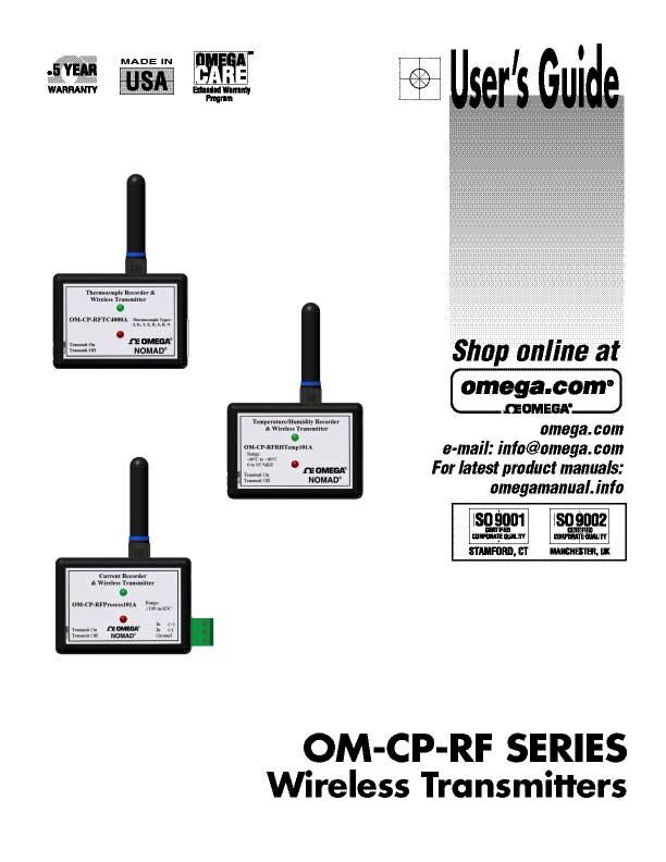
4 Omega Engineering, Inc. Operations Manual for OM-CP-RF Series Data Loggers INTRODUCTION Omega s OM-CP-RF series line of wireless-enabled data loggers provides a simple, lowcost wireless solution for short-range data collection applications. These products are powered by a user-replaceable internal battery and can be configured for up to ten years of battery life. They are designed for one-way, low data-rate applications, and transmit realtime data directly to a PC for monitoring. Like Omega s standard series of data loggers, they are simple to use and their versatile configuration options allow for easy integration into a wide variety of applications. The product line includes models for all the most popular commercial and industrial measurements, as shown in this table: PRODUCT DESCRIPTION OM-CP-RFTemp101A Temperature Recorder and Wireless Transmitter OM-CP-RFRHTemp101A Humidity / Temperature Recorder and Wireless Transmitter OM-CP-RFTC4000A Thermocouple Temperature Recorder and Wireless Transmitter OM-CP-RFRTDTemp101A RTD Temperature Recorder and Wireless Transmitter OM-CP-RFpHTemp101A ph / Temperature Recorder and Wireless Transmitter OM-CP-RFVolt101A DC Voltage Recorder and Wireless Transmitter OM-CP-RFProcess101A DC Current Recorder and Wireless Transmitter OM-CP-RFPulse101A Pulse Recorder and Wireless Transmitter These products have onboard memory in addition to the wireless transmitter, so they can completely replace existing data loggers and strip chart recorders while providing an added wireless data link. This memory can also serve as a failsafe backup, in the event of interference in the wireless channel or interruption of service to the monitoring computer. TRANSMITTER CHARACTERISTICS The transmitter used in the OM-CP-RF series products is a carrier present-carrier absent (CPCA) amplitude-modulated (AM) signal operating at a carrier frequency of 418 MHz. The data being transmitted is encoded similarly to standard RS232 serial data at a bit rate of 4,800 baud. This signal is detected by the RFC101A receiver module and converted to RS232 signals, which are passed to the COM port of the monitoring PC. The transmitter type and encoding method permit the device to use the maximum allowable output power specified by the FCC, and also minimizes the amount of battery power required for the transmission. This gives the user the best possible range, and also ensures a long battery life. To conform to FCC Part rules, the data transmission takes less than one second and the minimum periodic transmission rate allowed by the device is 30 seconds. The low duty cycle permits several devices to use the same communication band and receiver without excessive interference caused by talking over each other. Omega Engineering, Inc. Revised 04/07/05 Page 2 of 18

5 TRANSMISSION DISTANCE The transmission distance achievable with any wireless system is dependent on many factors. The only consistent measurement of transmission distance that can be used with these devices is called the line-of-sight transmission distance. The transmitter and receiver are set up in a large open area, free of obstacles and interference, and are aligned so their antennas are oriented in the same direction. Under these circumstances, the OM- CP-RF series products can achieve up to 120 feet (36 m) transmission range. SYSTEM COMPONENTS AND SETUP The following components are required to successfully set up and use the OM-CP-RF series products: A personal computer running the Windows operating system (Windows 95 or higher) One of the OM-CP-RF series wireless-enabled data loggers An RFC101A wireless receiver module and power supply, for receiving wireless transmissions from the data logger An IFC110 interface cable, for communicating with the wireless data logger Omega Data Recorder software, included with the RFC101A or IFC110 To configure the data logger, and register it on the PC for data reception, connect it to the PC through the IFC110 serial interface cable as shown in Figure 1 below. Figure 1. Connecting the IFC110 interface cable To set up the system for receiving wireless data, connect the RFC101A to the PC and plug in the power supply to a 110VAC outlet (as shown in Figure 2). In most cases, the IFC110 will need to be removed from the PC to connect the RFC101A. If there are multiple COM ports available on the PC, the RFC101A may be connected to a different COM port than the IFC110, thus leaving IFC110 connected. To switch between using the IFC110 and RFC101A, simply change to the appropriate COM port under the Communications menu. Omega Engineering, Inc. Revised 04/07/05 Page 3 of 18
 allows the user to")

6 Figure 2. Connecting the RFC101A wireless receiver WIRELESS CONFIGURATION DIALOG Figure 3. The Wireless Configuration dialog The Wireless Configuration dialog (shown in Figure 3) allows the user to select from a variety of operating modes to meet the requirements of different monitoring systems. To access this dialog, identify the device using the Device -> Identify Device and Read Status Omega Engineering, Inc. Revised 04/07/05 Page 4 of 18
7 menu item, switch to the Device Detail tab, and click the Wireless Configuration button. To edit the configuration, press the Change button in the dialog, make the appropriate changes, then press the Save button to commit the changes to the device. Note: Closing the dialog or exiting with the OK button will not store the changes in the device. To comply with FCC regulations, saving a configuration change may cause the device to inhibit output from the transmitter while the internal timers synchronize to the new configuration (this may be the longer of the reading interval or custom transmit interval). To force synchronization of the timers and enable output before the aforementioned interval has passed, restart the device from the software. Transmitter Output Modes Real-time data transmissions may be sent through the RF antenna, the device s serial port, both or neither. If both the serial and RF transmitters are disabled, the device will function strictly as a standard data logger. The typical user will configure the device for wireless transmission only thus transmitting data from the device to the RFC101A receiver. However, serial transmission may be desirable for some systems where the built-in transmitter is not powerful enough to maintain a reliable link, the signal must be brought outside of an environment that blocks RF, or when a hardwired connection to an alternate transmitter is required. Additionally, both modes may be enabled for combined local and long-distance monitoring of the signal. See Increasing Range with the RFExtender later in this manual. Transmitter Options The transmitter module has four configuration options. Two of these options pertain to enabling and disabling the transmitter under different operating conditions and two pertain to the timing and format of the transmitted signal. These options are summarized below. 1. Transmit only while logging If this option is selected, the transmitter will only output data when the logger is recording data to memory. When memory is filled and the device stops logging, the transmitter will stop as well to indicate the logger needs to be offloaded and restarted. If the memory wrap-around mode of the logger is enabled, the device will continue to overwrite the oldest internal data and continue transmitting data wirelessly. If this transmitter option is not selected, the transmitter will continue to operate regardless of whether the device is recording data. 2. Transmit under switch control If this option is selected, the on/off switch may be used to inhibit the transmitter output. This allows the user to manually stop the transmitter without affecting the logger operation or transmission timing. This may be useful for transporting the device through an area where other devices are operating on the same frequency band, disabling the transmitter until the device is placed in-system, or disabling individual devices to evaluate system performance and troubleshoot interference or collisions. In systems where a manual override is not desirable, this option may be left unchecked, and the transmitter will not be affected by the position of the switch. Note: The above two transmitter options function as such: if either one of the modes would disable the transmitter under given conditions, the transmitter will be disabled. For the transmitter to be enabled, the required conditions must be met for both options to allow the transmission. Omega Engineering, Inc. Revised 04/07/05 Page 5 of 18
8 3. Randomize transmit interval If this option is selected, the transmitter will wait a short random delay of up to 5 seconds before it transmits each data packet. This can decrease the chances of lost packets due to devices talking over each other because of long-term timer drift. Devices that are initially synchronized to transmit 10 seconds apart can drift in their timekeeping by up to 2 seconds per day, meaning that they could potentially interfere with each other after a few days of sustained operation. Because the transmission lasts less than a second, a random delay of up to 5 seconds can allow the majority of the transmissions to escape interference. If this transmitter option is not selected, the device will transmit at the interval set by its timer to within a few milliseconds. It is then up to the user to make any necessary accommodations for the timer drift. See Using Multiple Devices later in this manual. 4. Use error correction If this option is selected, the transmitter output format will be modified to include a simple forward error correction scheme known as a Hamming code. This method of error correction allows the receiver in a one-way transmission to correct any single bit error in each block of eight data bits being received. This option may help to increase system reliability in some environments. Note: System reliability will most commonly be degraded by loss of signal or by burst noise longer than a single bit, thus this option may not substantially improve performance for the typical user. Additionally, if this option is not selected, the device may be able to transmit two complete copies of the data packet, increasing the likelihood that one of the copies will be received even when the other is lost due to interference. (Each packet always contains error detection, to ensure that invalid data is not displayed.) Custom Transmit Interval By default, the transmitter module will transmit a data packet with each internally recorded data point, or if it is not recording, at the reading rate specified for the data logger. This option allows the user to specify a custom transmit interval that will be used only by the transmitter. Like the data logger reading rate, this interval is limited to a minimum of 30 seconds and a maximum of 12 hours, but unlike the reading rate it may be set to any multiple of 10 seconds. Additionally, the device can be configured to return new data every interval, or to repeatedly send the data from the most recent internally recorded reading. This option can be useful for the following reasons: 1. Real-time monitoring Some applications may require relatively quick feedback of trend data to the user, but only need to be recorded at longer intervals. With this option, for example, an operator could check the trend of a system every 10 minutes and make necessary adjustments to keep the system within specifications, but the official logger record of the data only needs to indicate the value on an hourly basis. 2. Increasing system reliability In applications where the operating environment is unfriendly to RF, this option can be used to repeat the same data multiple times to increase the probability of successful reception. If the logger is recording every 5 minutes, the transmitter can be configured to send the data from the last reading every 30 seconds, allowing for 10 transmissions per logger reading. If the environment sees a burst of RF interference a few times per minute, it is highly probable that one or more transmissions will be received properly. Omega Engineering, Inc. Revised 04/07/05 Page 6 of 18
9 3. Staggering transmissions from multiple devices If several devices need to record data at the same time while transmitting the output in real time, this option can be used to ensure that at least one transmission from each device is sent without interference from the other devices. This is similar to the randomization option provided above, but is better suited to some applications. See Using Multiple Devices later in this manual. Indicator Mode The device may be configured to blink the LED activity indicator every 10 seconds (the factory default setting) or only when a scheduled reading is taken. The green LED indicator will blink to indicate that the device is configured properly to allow a wireless transmission to occur. If the wireless transmitter is disabled by any of the available configuration options (by setting the transmitter output mode to disable the wireless output, or by selecting either of the related transmitter control options), the indicator will not blink. When a wireless transmission is about to be sent, both the green and the red LED indicators will blink. The primary reason to turn off the 10-second indicator is to conserve battery capacity. See Battery Life later in this manual. The 10-second mode is forced on if the custom transmit interval discussed above is enabled. REGISTERING THE DEVICE ON A SYSTEM Before the Omega software will receive data from an OM-CP-RF-series transmitter, the device must be properly registered on the system. When the device is identified or configured, the PC software will store an image of the device for future reference. This image is stored on the PC s hard disk so it is retained even when the software or PC is shut down. The software then refers to the device image when receiving a transmission to fill in the information that is not transmitted in the data packet. This information includes the device ID, calibration data, and measurement variables such as a thermocouple type or engineering units. The data packet contains a checksum of critical settings to ensure invalid data is not displayed. For this reason, the device must be re-registered if it is calibrated or the measurement data is changed on another PC. STARTING THE DEVICE AND SYNCHRONIZING THE TRANSMITTER Like other Omega data loggers, the OM-CP-RF series devices must be configured through a PC. The wireless transmitter is primarily set up through the Wireless Configuration dialog discussed previously, but synchronization of the transmitter to the desired starting time is accomplished through the Start Device dialog when launching the data logger. When launching, choose the start time, and set the logger parameters (device ID and reading rate) for the run. When the device is started, both the logger and transmitter time base will be set for the selected start time. They will remain inactive until the selected time, and then begin to operate as configured in the Start Device and Wireless Configuration dialogs. When the delay-start time arrives, the logger will take readings (if enabled) at the programmed reading rate, and wireless transmissions (if enabled) will be made at the reading rate or custom interval, depending on how the device is configured. If a delayed start is specified, the device will remain completely inactive during the start delay period. The indicators will not blink, no readings will be taken and no transmissions will be sent. It will continue to communicate normally, and may be queried, stopped, or Omega Engineering, Inc. Revised 04/07/05 Page 7 of 18
10 restarted. If the application only requires the wireless transmitter without data logging capability, the device may be stopped immediately (when the Transmit only while logging option is not selected) after launching without affecting the scheduled start of the wireless transmissions. This will marginally improve the battery life when data logging capability is not required. If immediate start is specified, the device will begin logging immediately, but it will inhibit transmitter output for the first reading to comply with FCC regulations. To ensure the first transmission is sent, use the delayed start mode with a 1-2 minute delay (minimum allowed by software). USING MULTIPLE DEVICES When using more than one RF transmitter, should transmissions overlap, it is certain that one or both of the transmissions will be lost. There are several methods, described below in order of complexity (least to most), to circumvent this issue: 1. Rely on the logged data - The OM-CP-RF transmitters can be configured to log all data to non-volatile memory. If a data point is lost, it may be fully recovered by a later off-load. 2. Provide a direct connection - If it is possible to have a PC always connected to the OM-CP-RF series logger (while monitoring via RF elsewhere), then using the serial output transmitter mode or the real-time chart recording feature of the software will avoid RF interference. 3. Randomize the transmission interval This option is selected from the wireless configuration menu. Selecting this option will cause the transmitter to wait a short random delay of up to 5 seconds before it transmits each data packet. Should two transmitters drift to within 5 seconds of each other, this feature will reduce the dropped points by about 80% until the transmitter clocks drift apart again. This will also decrease the chances of sequential lost packets. 4. Staggering of scheduled transmissions By starting the OM-CP-RF transmitters at different times, the transmissions will not overlap until the time drift between the transmitter clocks causes transmission collisions. At room temperature, the typical clock will drift no more than 1-2 seconds per day. Higher or lower temperatures will cause more drift. For example: if you use delay start to start one transmitter at 11:00:00 and a second transmitter at 11:00:30 (at 1 minute sample rates), then typically they would run for about 30 days (at similar temperatures) before there was a possibility of a collision. However, temperature fluctuations that deviate up or down from room temperature will generally cause the clock to run slower. Thus, potential collisions depend the time between samples, relative clock accuracy and relative ambient temperatures. 5. Prime number scheduled transmissions This method utilizes prime numbers to help prevent transmission collisions. See the next section for further detail on this method. Omega Engineering, Inc. Revised 04/07/05 Page 8 of 18
11 PREVENTING COLLISIONS WITH PRIME NUMBERS As mentioned in the previous section, prime numbers can be helpful in preventing collisions, allowing the maximum amount of data to be received from every transmitter. This section will outline the steps to follow to select the best transmission intervals, and provide a worked example. Using prime numbers is advantageous because the common multiples of two prime numbers are farther apart than the multiples of two nearby non-primes. (For example, the numbers 8 and 12 have a common multiple at 24, 48, 72, etc., while 7 and 11 have their first common multiple at 77.) So, if two transmitters were set up to transmit at 8 and 12 minutes respectively, a collision (and a lost transmission) would occur every 24 minutes, much more often than if they were set up to transmit at 7 and 11 minutes. When expanding to 3 or more transmitters, this property is even more pronounced. The size of the prime number matters as well. For larger prime numbers, fewer collisions will occur in a given amount of time. Finally, to minimize the impact of the collisions that do occur, the transmitter should be configured to transmit the same data at least twice for every reading. This can be accomplished using the Return most recently recorded data only option in the Wireless Configuration dialog. For two transmitter systems, this ensures that every reading will have at least one clear slot for transmission. If two transmitters collide during the first transmission attempt, they cannot possibly collide during the second (they are scheduled to select different sots for the second attempt). For three or more transmitters, it is possible to collide with one transmitter on the first attempt and another on the second attempt, but the number of these sequential collisions is very small. The general procedure for selecting transmission intervals follows below. It assumes that all the transmitters will be recording data at the same rate. 1. Determine the number of transmitters Determine the number of points that need to be monitored, and select the transmitters that will cover those points most efficiently. 2. Determine the reading interval The reading interval selected for the devices should be the longest interval that will provide the data needed for the application. 3. Select the prime numbers The transmission intervals must always be a multiple of 10 seconds. So, divide the reading interval (in seconds) by 20, and pick the largest prime numbers that are less than this value. This ensures that there will always be at least two transmission slots per reading for each transmitter. Prime numbers in the necessary range are listed in Table Assign the transmission intervals Multiply the prime numbers selected in step 3 by 10, and assign them to the transmitters. If some transmitters are monitoring more critical data than others, they may be assigned the smaller or larger numbers depending on the application. If the smallest numbers are substantially less than half the reading interval (e.g. 130 seconds for a 10 minute reading interval), assign them to the more critical transmitters to increase the number of transmissions per reading. If the smaller numbers are close to half the reading interval, assign the Omega Engineering, Inc. Revised 04/07/05 Page 9 of 18
12 larger numbers to the critical transmitters, as the larger numbers will experience slightly fewer collisions. 5. Configure and launch the devices In the Wireless Configuration dialog, enable the custom transmit interval, and select the Return most recently recorded data only option for each device. Enter the proper transmission interval in seconds (be careful not to enter the number incorrectly as hours/minutes/seconds), and save the configuration before exiting the dialog. When launching the devices, use delayed start mode to begin the transmission schedules at the same time, and select the reading interval determined in step 2. Table 1. Prime numbers from 3 to Omega Engineering, Inc. Revised 04/07/05 Page 10 of 18
13 Prime Number Examples Two examples are provided in Table 2 below to illustrate the procedure. Notice that increasing the reading interval by a factor of 6 (1 hour instead of 10 minutes) results in an increase by a factor of 540 in the time before data is lost (45 days instead of 2 hours)! Table 2. Prime number examples Example 1 Example 2 Number of Transmitters 5 5 Reading Interval 10 minutes (600 seconds) 1 hour (3600 seconds) Max Transmission Interval 300 seconds (= 600/2) 1800 seconds (= 3600/2) Max Prime Number 30 (= 300/10) 180 (= 1800/10) Selected Prime Numbers 29, 23, 19, 17, , 173, 167, 163, 157 Transmission Intervals * More critical devices 290 seconds 230 seconds 190 seconds* 170 seconds* 130 seconds* 1790 seconds* 1730 seconds* 1670 seconds 1630 seconds 1570 seconds First Lost Reading After > 2 hours > 45 days INCREASING RANGE WITH THE RFEXTENDER The RFExtender products can extend the transmission distance of Omega s OM-CP-RF series products for up to 1 mile (1.6 km) under ideal conditions. Typical ranges are 1000 to 2000 feet (300 to 600 m) outdoors, and up to 300 feet (100 m) indoors. An RFExtender system requires a minimum of two RFExtender transceivers, one at each node of the wireless link. The RFExtender transceivers require AC power. Simple RFExtender System A basic set-up might be one of the two configurations below: Figure 4. RFExtender as a wireless repeater Omega Engineering, Inc. Revised 04/07/05 Page 11 of 18
14 Figure 5. RFExtender as a wireless communication interface In either configuration, the RFExtender functions like an extension cable between the logger interface and the PC. The primary difference between the two setups is the logger interface that is connected to the RFExtender. Figure 4 uses an RFC101A, and is therefore limited by the one-way communication between the OM-CP-RF data logger and the RFC101A. Just like using the RFC101A by itself, this setup requires that the logger be brought back to the PC and connected to an IFC110 interface cable to launch, download, or configure the logger. Figure 5 allows two-way communication through the IFC110 and thus can allow full use of the data logger features. The setup in Figure 4 is necessary when several transmitters must send their data to the same RFExtender. The data is received by the RFC101A, and retransmitted or repeated to the PC. Figure 5 is appropriate when only one data logger needs to be used with a particular RFExtender. The data logger is configured to transmit data packets over the serial cable instead of through the wireless transmitter, and the RFExtender transmits the serial data back to the PC. This setup has two advantages: the logger can be launched, downloaded, and configured without bringing it back to the PC, and the IFC110 interface cable is less expensive than the RFC101A. Complex RFExtender System It is possible to use more than two RFExtenders in a system with more than two nodes. This type of setup will be an extension of the two simple setups demonstrated above. Refer to Figure 6 for an example of a complex system. The setup in Figure 6 shows an RFExtender connected to a PC that can receive data from 8 other transceivers. Each of the remote transceivers can either communicate serially with one logger via an IFC110 or receive wireless data from multiple OM-CP-RF series transmitters through an RFC101A. For this system to function properly, each transceiver must be set up to receive data only from the proper location. This is accomplished by assigning each transceiver a unique module address to identify itself, and a receiver address mask to identify the module addresses from which it will receive data. Module Address and Receiver Address Mask The module address provides a unique identification of the individual transceivers. It consists of 4 hexadecimal digits, which can be divided between a system number and a Omega Engineering, Inc. Revised 04/07/05 Page 12 of 18
15 node address within that system. Most applications will us a module address of the format XXYY, where XX is the system number and YY is the node address. A system is comprised of a PC connected to an RFExtender transceiver (the Local Node ) and several other transceivers ( Remote Nodes ) set up within the transmission range. Using the system number is not strictly necessary, but it allows several groups of transceivers to be located within transmission distance of each other without allowing data from one group to be received by the other. The receiver address mask is also 4 digits and will usually be configured in one of two ways: to receive data from all the modules within a system, or to receive data only from another module with the same module address. Only the local node at the PC will be configured to receive from multiple modules, as only the PC is capable of receiving and processing the data being transmitted by all the modules. The remote nodes will be assigned individual addresses, and configured only to accept transmissions from a module with the same address as their own. To allow two-way communication with a remote node, the local node module address and receiver address mask will be changed temporarily to match that of the remote node. Assigning module addresses should begin with the determination of the system number. The system numbers used may be sequential, starting with one, as the zero address has special significance. The local node should be assigned node address zero, and the remote nodes may be sequential starting with one. Note that this is how the module addresses in Figure 6 were generated. The receiver address mask instructs the transceiver which data to receive by indicating what part of the incoming module address should be compared to its own module address. The remote nodes should be assigned receiver address masks of FFFF. In general terms, a hexadecimal digit F in the receiver address mask means compare this digit. So a receiver address mask of FFFF means compare all the digits, and if all the digits do not match, ignore the incoming data. In technical terms, the comparison is performed as a logical AND operation, which is a common function in computers and digital circuits. The local node in Figure 6 is assigned an address mask of FF00. This can be interpreted as compare the system number, but not the node number. (Technically, the AND function will always result in a node address of 00.) This way, the PC will receive data from all the transceivers in its system. Receiver Address Mask Example The local node in Figure 6 has a module address of 0100 and a receiver address mask of FF00. Suppose that it receives data from module address The incoming address is processed through the mask as 0104 AND FF00 = The result matches the local node address of 0100, so the transceiver passes the data through. Likewise, suppose that module address 0104 receives data from module address The incoming address is processed through the mask as 0108 AND FFFF = The result does not match the receiver s module address of 0104, so the receiver ignores the data. For further information on uses of the module address and receiver address mask, contact Omega Technical Support. Omega Engineering, Inc. Revised 04/07/05 Page 13 of 18


16 Node Node Node 0108 FFFF 0100 FF FFFF Node 0107 FFFF Local Node 0102 FFFF 0106 FFFF Node Node Node 0103 FFFF Node 0105 FFFF 0104 FFFF ADDRESS MASK RFEXTENDER TRANSCIEVER RF SERIES DATA LOGGER RFC101A WIRELESS RECEIVER IFC110 INTERFACE CABLE Figure 6. A complex RFExtender system WIRELESS LINK CABLE LINK Omega Engineering, Inc. Revised 04/07/05 Page 14 of 18
17 BATTERY LIFE There are many variables that affect the battery lifetime. These variables include (but are not limited to) sample rate, transmit rate, LED settings, transmission settings, ambient temperature and battery self-discharge. For the purposes of approximating battery life, please consult Tables 3 and 4 below. These numbers should not be used as an absolute guarantee, but as an approximate guide for deciding when the battery will need replacement. This table is useful because the lithium batteries used in the OM-CP-RF products do not show a strong correlation between voltage and remaining capacity, which makes it very difficult to measure their remaining life. In lithium batteries, the voltage stays very nearly constant for the entire life of the battery until it drops sharply and suddenly when depleted. There are variables that it is not possible to account for in the tables. The table assumes a pattern of continuous use, in which both the logger and transmitter features are used such that both the transmitter and logger are active at approximately the indicated activity rate (for cases where the logger and transmitter operate at different rates, use the faster rate for estimation). The calculations assume that the device is configured and deployed, then downloaded and redeployed when the logger is nearly full. Table 3. Estimated battery life ACTIVITY RATE WORST CASE FACTORY DEFAULT BEST CASE 30 seconds 3 months 6 months 6 months 1 minute 6 months 12 months 12 months 2 minutes 12 months 20 months 24 months 3 minutes 15 months 27 months 3 years 4 minutes 21 months 33 months 3.5 years 5 minutes 24 months 3 years 4 years 6 minutes 27 months 3.5 years 5 years 8 minutes 33 months 4 years 6 years 10 minutes 3 years 4.5 years 7 years 15 minutes 4 years 5 years 8.5 years 30 minutes 5 years 6 years 10+ years 1 hour 6 years 6.5 years 10+ years 2 hours 6.5 years 7 years 10+ years 4 hours 7 years 7+ years 10+ years The transmitter settings used to calculate the best, worst and factory default cases are indicated in Table 4. Table 4. Transmitter settings for battery life estimation WORST CASE FACTORY DEFAULT BEST CASE Wireless Output Enabled Enabled Enabled Serial Output Not Significant Not Significant Not Significant Logging Option Not Significant Not Significant Not Significant Switch Option Not Significant Not Significant Not Significant Randomization Enabled Disabled Disabled Error Correction Enabled Disabled Enabled Omega Engineering, Inc. Revised 04/07/05 Page 15 of 18
18 Custom Interval Enabled Disabled Disabled Sampling Option Not Significant Not Applicable Not Applicable Indicator Mode 10 seconds 10 seconds Reading only Even longer battery life can be achieved by disabling the wireless output in favor of serial-only or no transmission. Battery life is not calculated for these unusual cases. OPERATING ENVIRONMENT The OM-CP-RF series data loggers are rated for 30 to +70 C and up to 95 %RH (noncondensing). Although the devices are fully functional over this range, the strength of the wireless output signal may vary with changes in environment. In particular, the signal strength may be reduced at the temperature extremes, in high humidity, or if humidity condenses inside the device. SYSTEM PERFORMANCE AND RELIABILITY To achieve maximum distance for the wireless transmission, there are a number of guidelines that should be followed. Consider these points when setting up the system: Transmitter location Keep the transmitter as close to the receiver as possible. If either the transmitter or receiver must be in an enclosed area, keep the other inside the same area. This is especially important if there would be metal walls, conduit, or wires between the units. In particular, attempting to transmit from inside of a freezer or refrigerator is not likely to be successful. Line of sight Try to keep the transmitting and receiving antennas along a direct line of sight from one to the other. Keep the number of corners or obstacles in between them to a minimum. Nearby objects Try to keep the transmitting and receiving antennas away from any foreign objects, especially those made of metal. Performance may be improved by moving the antenna away from the ground, ceiling, or nearby objects. Antenna orientation Keeping the transmitting and receiving antennae parallel with one another may improve performance. Minimize interference Keep external sources of radio frequency noise to a minimum. Locate the antenna and receiver as far from any other electrical or wireless devices as possible. If multiple transmitters are being used, set up the system to minimize interference between transmitters. Omega Engineering, Inc. Revised 04/07/05 Page 16 of 18
19 FCC COMPLIANCE AND REQUIREMENTS Omega s OM-CP-RF series products operate in an unlicensed operation band, meaning the end-user does not need to do anything special (such as obtain a license) to legally make use of the product. Omega has performed all the required testing and certification to ensure that these products meet the requirements for unlicensed operation outlined in 47 CFR Part of the FCC rules. However, the user must understand and adhere to the following notes and guidelines: Any user changes or modifications that are not expressly approved by Omega Engineering, Inc. may void the user s authority to operate the device per FCC code, section FEDERAL COMMUNICATIONS COMMISSION (FCC) NOTICE The following FCC IDs are associated with the devices covered by this manual: PRODUCT FCC ID TRADE NAME OM-CP-RFTemp101A RUYBOARDRF Omega Engineering, Inc. OM-CP-RFRHTemp101A RUYBOARDRF Omega Engineering, Inc. OM-CP-RFTC4000A RUYBOARDRF Omega Engineering, Inc. OM-CP-RFRTDTemp101A RUYBOARDRF Omega Engineering, Inc. OM-CP-RFpHTemp101A RUYRFPHTEMP Omega Engineering, Inc. OM-CP-RFVolt101A RUYBOARDRF Omega Engineering, Inc. OM-CP-RFProcess101A RUYBOARDRF Omega Engineering, Inc. OM-CP-RFPulse101A RUYBOARDRF Omega Engineering, Inc. The following statement applies to all of the devices covered in this manual: This device complies with Part 15 of the FCC Rules. Operation is subject to the following two conditions: (1) this device may not cause harmful interference and (2) this device must accept any interference received, including interference that may cause undesired operation. NOTE: This equipment has been tested and found to comply with the limits for a Class B digital device, pursuant to Part 15 of the FCC Rules. These limits are designed to provide reasonable protection against harmful interference in a residential installation. This equipment generates, uses and can radiate radio frequency energy and, if not installed and used in accordance with the instructions, may cause harmful interference to radio communications. However, there is no guarantee that interference will not occur in a particular installation. If this equipment does cause harmful interference to radio or television reception, which can be determined by turning the equipment off and on, the user is encouraged to try to correct the interference by one of more of the following measures: Reorient or relocate the receiving antenna. Increase the separation between the equipment and receiver. Connect the equipment into an outlet on a circuit different from that to which the receiver is connected. Consult the dealer or an experienced radio/tv technician for help. Omega Engineering, Inc. Revised 04/07/05 Page 17 of 18
20 INDUSTRY CANADA (IC) NOTICE The following IC identification numbers are associated with the devices covered by this manual. These certifications/registrant numbers are displayed on the labels of the products. Removal or defacement of these numbers will void the IC certification. PRODUCT IC # TRADE NAME OM-CP-RFTemp101A 4953A-BOARDRF Omega Engineering, Inc. OM-CP-RFRHTemp101A 4953A-BOARDRF Omega Engineering, Inc. OM-CP-RFTC4000A 4953A-BOARDRF Omega Engineering, Inc. OM-CP-RFRTDTemp101A 4953A-BOARDRF Omega Engineering, Inc. OM-CP-RFpHTemp101A 4953A-RFPHTEMP Omega Engineering, Inc. OM-CP-RFVolt101A 4953A-BOARDRF Omega Engineering, Inc. OM-CP-RFProcess101A 4953A-BOARDRF Omega Engineering, Inc. OM-CP-RFPulse101A 4953A-BOARDRF Omega Engineering, Inc. CONTACT INFORMATION For further information on the products described in this manual, contact: Omega Engineering, Inc. One Omega Drive Stamford, Connecticut P.O. Box 4047 Phone: (203) Fax: (203) Toll Free: (800) Web: Omega Engineering, Inc. Revised 04/07/05 Page 18 of 18
21 WARRANTY/DISCLAIMER OMEGA ENGINEERING, INC. warrants this unit to be free of defects in materials and workmanship for a period of 61 months from date of purchase. OMEGA s WARRANTY adds an additional one (1) month grace period to the normal five (5) year product warranty to cover handling and shipping time. This ensures that OMEGA s customers receive maximum coverage on each product. If the unit malfunctions, it must be returned to the factory for evaluation. OMEGA s Customer Service Department will issue an Authorized Return (AR) number immediately upon phone or written request. Upon examination by OMEGA, if the unit is found to be defective, it will be repaired or replaced at no charge. OMEGA s WARRANTY does not apply to defects resulting from any action of the purchaser, including but not limited to mishandling, improper interfacing, operation outside of design limits, improper repair, or unauthorized modification. This WARRANTY is VOID if the unit shows evidence of having been tampered with or shows evidence of having been damaged as a result of excessive corrosion; or current, heat, moisture or vibration; improper specification; misapplication; misuse or other operating conditions outside of OMEGA s control. Components in which wear is not warranted, include but are not limited to contact points, fuses, and triacs. OMEGA is pleased to offer suggestions on the use of its various products. However, OMEGA neither assumes responsibility for any omissions or errors nor assumes liability for any damages that result from the use of its products in accordance with information provided by OMEGA, either verbal or written. OMEGA warrants only that the parts manufactured by the company will be as specified and free of defects. OMEGA MAKES NO OTHER WARRANTIES OR REPRESENTATIONS OF ANY KIND WHATSOEVER, EXPRESSED OR IMPLIED, EXCEPT THAT OF TITLE, AND ALL IMPLIED WARRANTIES INCLUDING ANY WARRANTY OF MERCHANTABILITY AND FITNESS FOR A PARTICULAR PURPOSE ARE HEREBY DISCLAIMED. LIMITATION OF LIABILITY: The remedies of purchaser set forth herein are exclusive, and the total liability of OMEGA with respect to this order, whether based on contract, warranty, negligence, indemnification, strict liability or otherwise, shall not exceed the purchase price of the component upon which liability is based. In no event shall OMEGA be liable for consequential, incidental or special damages. CONDITIONS: Equipment sold by OMEGA is not intended to be used, nor shall it be used: (1) as a Basic Component under 10 CFR 21 (NRC), used in or with any nuclear installation or activity; or (2) in medical applications or used on humans. Should any Product(s) be used in or with any nuclear installation or activity, medical application, used on humans, or misused in any way, OMEGA assumes no responsibility as set forth in our basic WARRANTY/DISCLAIMER language, and, additionally, purchaser will indemnify OMEGA and hold OMEGA harmless from any liability or damage whatsoever arising out of the use of the Product(s) in such a manner. RETURN REQUESTS/INQUIRIES Direct all warranty and repair requests/inquiries to the OMEGA Customer Service Department. BEFORE RETURNING ANY PRODUCT(S) TO OMEGA, PURCHASER MUST OBTAIN AN AUTHORIZED RETURN (AR) NUMBER FROM OMEGA S CUSTOMER SERVICE DEPARTMENT (IN ORDER TO AVOID PROCESSING DELAYS). The assigned AR number should then be marked on the outside of the return package and on any correspondence. The purchaser is responsible for shipping charges, freight, insurance and proper packaging to prevent breakage in transit. FOR WARRANTY RETURNS, please have the following information available BEFORE contacting OMEGA: 1. Purchase Order number under which the product was PURCHASED, 2. Model and serial number of the product under warranty, and 3. Repair instructions and/or specific problems relative to the product. FOR NON-WARRANTY REPAIRS, consult OMEGA for current repair charges. Have the following information available BEFORE contacting OMEGA: 1. Purchase Order number to cover the COST of the repair, 2. Model and serial number of the product, and 3. Repair instructions and/or specific problems relative to the product. OMEGA s policy is to make running changes, not model changes, whenever an improvement is possible. This affords our customers the latest in technology and engineering. OMEGA is a registered trademark of OMEGA ENGINEERING, INC. Copyright 2004 OMEGA ENGINEERING, INC. All rights reserved. This document may not be copied, photocopied, reproduced, translated, or reduced to any electronic medium or machine-readable form, in whole or in part, without the prior written consent of OMEGA ENGINEERING, INC.
22 Where Do I Find Everything I Need for Process Measurement and Control? OMEGA Of Course! Shop online at omega.com TEMPERATURE Thermocouple, RTD & Thermistor Probes, Connectors, Panels & Assemblies Wire: Thermocouple, RTD & Thermistor Calibrators & Ice Point References Recorders, Controllers & Process Monitors Infrared Pyrometers PRESSURE, STRAIN AND FORCE Transducers & Strain Gages Load Cells & Pressure Gages Displacement Transducers Instrumentation & Accessories FLOW/LEVEL Rotameters, Gas Mass Flowmeters & Flow Computers Air Velocity Indicators Turbine/Paddlewheel Systems Totalizers & Batch Controllers ph/conductivity ph Electrodes, Testers & Accessories Benchtop/Laboratory Meters Controllers, Calibrators, Simulators & Pumps Industrial ph & Conductivity Equipment DATA ACQUISITION Data Acquisition & Engineering Software Communications-Based Acquisition Systems Plug-in Cards for Apple, IBM & Compatibles Datalogging Systems Recorders, Printers & Plotters HEATERS Heating Cable Cartridge & Strip Heaters Immersion & Band Heaters Flexible Heaters Laboratory Heaters ENVIRONMENTAL MONITORING AND CONTROL Metering & Control Instrumentation Refractometers Pumps & Tubing Air, Soil & Water Monitors Industrial Water & Wastewater Treatment ph, Conductivity & Dissolved Oxygen Instruments M4113/1204
User s Guide. TX905 Field Rangeable Voltage Input Two-Wire Transmitter. Shop online at
 O N User s Guide Shop online at TX905 Field Rangeable Voltage Input Two-Wire Transmitter omega.com e-mail: info@omega.com For latest product manuals: omegamanual.info OMEGAnet On-Line Service omega.com
User s Guide CL309A Milliamp Loop Calibrator. Shop online at omega.com SM
 User s Guide Shop online at omega.com SM e-mail: info@omega.com For latest product manuals: www.omegamanual.info 4-20 Milliamp Loop Calibrator omega.com info@omega.com Servicing North America: U.S.A.:
User s Guide TX94A-SS. Stainless Steel RTD Temperature Transmitter. Shop online at
 MADE IN User s Guide Shop online at omega.com e-mail: info@omega.com For latest product manuals: omegamanual.info TX94A-SS Stainless Steel RTD Temperature Transmitter OMEGAnet Online Service omega.com
User s Guide. TX94 RTD Temperature Transmitter. Shop online at. omega.com For latest product manuals: omegamanual.
 User s Guide Shop online at TX94 RTD Temperature Transmitter omega.com e-mail: info@omega.com For latest product manuals: omegamanual.info OMEGAnet On-Line Service omega.com Servicing North America: U.S.A.:
User s Guide EWS-RH. Relative Humidity/Temperature Transmitter. Shop online at. MADE IN
 MADE IN User s Guide Shop online at www.omega.com e-mail: info@omega.com EWS-RH Relative Humidity/Temperature Transmitter OMEGAnet Online Service www.omega.com Internet e-mail info@omega.com Servicing
User s Guide TX92A. Miniature Temperature Transmitters. Shop online at omega.com
 TM User s Guide Shop online at omega.com e-mail: info@omega.com For latest product manuals: www.omegamanual.info TX92A Miniature Temperature Transmitters omega.com info@omega.com U.S.A. Headquarters: Servicing
User s Guide TX94A. Ultra-Miniature Temperature Transmitters. Shop online at omega.com
 TM User s Guide Shop online at omega.com e-mail: info@omega.com For latest product manuals: www.omegamanual.info TX94A Ultra-Miniature Temperature Transmitters omega.com info@omega.com U.S.A. Headquarters:
User s Guide CL535. Frequency Calibrator with Totalizer. Shop online at. omega.com For latest product manuals: omegamanual.
 MADE IN User s Guide Shop online at omega.com e-mail: info@omega.com For latest product manuals: omegamanual.info CL535 Frequency Calibrator with Totalizer OMEGAnet Online Service omega.com Internet e-mail
User s Guide. DMD-476-DC Bridgesensor DC Powered Signal Conditioner
 User s Guide An OMEGA Technologies Company www.omega.com e-mail:info@omega.com DMD-476-DC Bridgesensor DC Powered Signal Conditioner omega.com OMEGAnet On-Line Service http://www.omega.com Internet e-mail
OMEGA. EWSE Series. Rugged, Weatherproof Temperature Sensors and Transmitters. 1.0 Description. 2.0 Receiving and Unpacking
 NEWPORT EWSE Series Rugged, Weatherproof Temperature Sensors and Transmitters INSTRUCTION SHEET MUK001/0311 Shop online at: e-mail: sales@ For latest product manuals: 1.0 Description The EWSE air temperature
SPRTX SERIES. General Description. Unpacking
 SPRTX SERIES Industrial RTD Connector/Transmitter INSTRUCTION SHEET M3935/0311 Shop online at: omega.com e-mail: info@omega.com For latest product manuals: omegamanual.info General Description The OMEGA
User s Guide TX93. Thermocouple Two-Wire Temperature Transmitter. Shop online at
 User s Guide Shop online at TX93 Thermocouple Two-Wire Temperature Transmitter omega.com e-mail: info@omega.com For latest product manuals: omegamanual.info OMEGAnet On-Line Service omega.com Servicing
User s Guide DRF-POT FOR POTENTIOMETER INPUT, DRF-RES FOR RESISTANCE INPUT. DRF Series Signal Conditioners. Shop online at
 User s Guide Shop online at omega.com e-mail: info@omega.com For latest product manuals: omegamanual.info DRF-POT FOR POTENTIOMETER INPUT, DRF-RES FOR RESISTANCE INPUT DRF Series Signal Conditioners OMEGAnet
User's Guide FMG-1000-DLA. Shop online at. Data Logger. omega.com For latest product manuals: omegamanual.
 User's Guide Shop online at omega.com email: Info@omega.com For latest product manuals: omegamanual.info FMG-1000-DLA Data Logger Servicing North America: U.S.A.: One Omega Drive, P.O. Box 4047 ISO 9001
User s Guide HX94B SERIES. Temperature/Relative Humidity Transmitter. Shop online at omega.com SM
 User s Guide Shop online at omega.com SM e-mail: info@omega.com For latest product manuals: www.omegamanual.info HX94B SERIES Temperature/Relative Humidity Transmitter omega.com info@omega.com Servicing
User s Guide DRF-VDC FOR DC VOLTAGE INPUT DRF-VAC FOR AC VOLTAGE INPUT. DRF Series Signal Conditioners. Shop online at
 User s Guide Shop online at omega.com e-mail: info@omega.com For latest product manuals: omegamanual.info DRF-VDC FOR DC VOLTAGE INPUT DRF-VAC FOR AC VOLTAGE INPUT DRF Series Signal Conditioners OMEGAnet
User s Guide CCT-80. Strain Gage Signal Conditioners. M2218/1201
 User s Guide http://www.omega.com e-mail: info@omega.com CCT-80 Strain Gage Signal Conditioners M2218/1201 TM omega.com OMEGA OMEGAnet On-Line Service SM http://www.omega.com Internet e-mail info@omega.com
User s Guide EWS-BP-A. Barometric Pressure Transmitter. Shop online at omega.com
 User s Guide Shop online at omega.com e-mail: info@omega.com For latest product manuals: www.omegamanual.info EWS-BP-A Barometric Pressure Transmitter omega.com info@omega.com Servicing North America:
User s Guide CL514-PLUS. Automated Universal RTD Calibrator. Shop online at
 MADE IN User s Guide Shop online at omega.com e-mail: info@omega.com For latest product manuals: omegamanual.info CL514-PLUS Automated Universal RTD Calibrator OMEGAnet Online Service omega.com Internet
User s Guide FLSC-45/45B. Paddlewheel Signal Conditioner. Shop online at omega.com
 TM User s Guide Shop online at omega.com e-mail: info@omega.com For latest product manuals: www.omegamanual.info NORWALK, CT FLSC-45/45B Paddlewheel Signal Conditioner omega.com info@omega.com U.S.A. Headquarters:
Where Do I Find Everything I Need for Process Measurement and Control? OMEGA Of Course! Shop online at omega.com SM
 Where Do I Find Everything I Need for Process Measurement and Control? OMEGA Of Course! Shop online at omega.com SM TEMPERATURE MU Thermocouple, RTD & Thermistor Probes, Connectors, Panels & Assemblies
User s Guide TX91A. (J, K, T, E) 4-20 ma Mini Temperature Transmitter. Shop online at omega.com
 4-20 ma Mini Temperature Transmitter. Shop online at omega.com") TM User s Guide Shop online at omega.com e-mail: info@omega.com For latest product manuals: www.omegamanual.info TX91A (J, K, T, E) 4-20 ma Mini Temperature Transmitter omega.com info@omega.com U.S.A.
TM User s Guide Shop online at omega.com e-mail: info@omega.com For latest product manuals: www.omegamanual.info TX91A (J, K, T, E) 4-20 ma Mini Temperature Transmitter omega.com info@omega.com U.S.A.
CCT-22, CCT-23, CCT-24, CCT-25, CCT-26, CCT-27
 User s Guide http://www.omega.com e-mail: info@omega.com CCT-22, CCT-23, CCT-24, CCT-25, CCT-26, CCT-27 Thermocouple Input Signal Conditioners M2203/1201 TM omega.com OMEGA OMEGAnet On-Line Service SM
User s Guide DRF-FR FOR FREQUENCY INPUT. DRF Series Signal Conditioners. Shop online at
 User s Guide Shop online at omega.com e-mail: info@omega.com For latest product manuals: omegamanual.info DRF-FR FOR FREQUENCY INPUT DRF Series Signal Conditioners OMEGAnet On-Line Service Internet e-mail
User s Guide TX93A. (J, K, T, E) 4-20 ma Ultra-Miniature Temperature Transmitters. Shop online at omega.com
 4-20 ma Ultra-Miniature Temperature Transmitters. Shop online at omega.com") TM User s Guide Shop online at omega.com e-mail: info@omega.com For latest product manuals: www.omegamanual.info TX93A (J, K, T, E) 4-20 ma Ultra-Miniature Temperature Transmitters omega.com info@omega.com
TM User s Guide Shop online at omega.com e-mail: info@omega.com For latest product manuals: www.omegamanual.info TX93A (J, K, T, E) 4-20 ma Ultra-Miniature Temperature Transmitters omega.com info@omega.com
Where Do I Find Everything I Need for Process Measurement and Control? OMEGA Of Course!
 Where Do I Find Everything I Need for Process Measurement and Control? OMEGA Of Course! Shop online at omega.com SM TEMPERATURE MU Thermocouple, RTD & Thermistor Probes, Connectors, Panels & Assemblies
User s Guide EWS-RH. Relative Humidity/Temperature Transmitter. Shop online at. omega.com
 TM TM User s Guide Shop online at TM omega.com e-mail: info@omega.com For latest product manuals: www.omegamanual.info EWS-RH Relative Humidity/Temperature Transmitter U.S.A.: omega.com info@omega.com
User s Guide CL3515R. K/J/T/E/R/S/N/L/U/B/C Calibrator Thermometer. Shop online at omega.com SM
 User s Guide Shop online at omega.com SM e-mail: info@omega.com For latest product manuals: www.omegamanual.info CL3515R K/J/T/E/R/S/N/L/U/B/C Calibrator Thermometer omega.com info@omega.com Servicing
User s Guide CL510A. RTD Simulator. Shop online at. omega.com. For latest product manuals: omegamanual.info CL510A-1 CL510A-10
 OMEGAnet Online Service omega.com Internet e-mail info@omega.com MADE IN User s Guide Servicing North America: U.S.A.: Omega Engineering, Inc., One Omega Drive, P.O. Box 4047 ISO 9001 Certified Stamford,
OMEGA. HHM598C Digital Clamp-On Meter
 OMEGA HHM598C Digital Clamp-On Meter OMEGAnet SM On-Line Service http://www.omega.com omega.com TM Internet e-mail info@omega.com Servicing North America: USA: ISO 9001 Certified Canada: One Omega Drive,
User s Guide HX93A, HX93DA SERIES. RH/Temperature Transmitter. Shop online at. MADE IN
 MADE IN User s Guide Shop online at www.omega.com e-mail: info@omega.com HX93A, HX93DA SERIES OMEGAnet Online Service www.omega.com Internet e-mail info@omega.com Servicing North America: USA: One Omega
User s Guide. PCL1000 Multi-Function Calibrator. Shop online at omega.com. For latest product manuals:
 User s Guide Shop online at omega.com SM e-mail: info@omega.com For latest product manuals: www.omegamanual.info NORWALK, CT PCL1000 Multi-Function Calibrator U.S.A. Headquarters: omega.com info@omega.com
User's Guide FMG210/220 SERIES. Shop online at. Low Flow Magnetic Flow Meter
 User's Guide Shop online at omega.com email: Info@omega.com For latest product manuals: omegamanual.info FMG210/220 SERIES Low Flow Magnetic Flow Meter Servicing North America: U.S.A.: One Omega Drive,
User s Guide. DMD-465 Bridgesensor AC Powered Signal Conditioner
 User s Guide An OMEGA Technologies Company www.omega.com e-mail:info@omega.com DMD-465 Bridgesensor AC Powered Signal Conditioner omega.com OMEGAnet On-Line Service http://www.omega.com Internet e-mail
User s Guide HX71 SERIES. RH Probe/Transmitter. Shop online at omega.com SM. RoHS 2 Compliant
 RoHS 2 Compliant User s Guide HX71-NB MODEL Shop online at omega.com SM e-mail: info@omega.com For latest product manuals: www.omegamanual.info HX71 MODEL HX71 SERIES RH Probe/Transmitter omega.com info@omega.com
LDP6-CDC. Serial Communications Option Card M
 LDP6-CDC Serial Communications Option Card INSTRUCTION SHEET M4539-0607 Shop online at: omega.com e-mail: info@omega.com For latest product manuals: omegamanual.info DESCRIPTION This bulletin serves as
User s Guide JBOX Summing Box/Transmitter. Shop online at. omega.com For latest product manuals: omegamanual.
 User s Guide Shop online at omega.com e-mail: info@omega.com For latest product manuals: omegamanual.info JBOX-4800 Summing Box/Transmitter OMEGAnet Online Service omega.com Internet e-mail info@omega.com
User s Guide OS950 SERIES. Handheld Infrared Thermometers. Shop online at. omega.com.
 User s Guide Shop online at omega.com www.omega.com e-mail: info@omega.com OS950 SERIES Handheld Infrared Thermometers omega.com OMEGAnet On-Line Service www.omega.com Internet e-mail info@omega.com Servicing
User s Guide CL427. Documenting Multifunction Calibrator and Arbitrary Function Generator
 User s Guide Shop online at omega.com e-mail: info@omega.com For latest product manuals: omegamanual.info MADE IN TAIWAN CL427 Documenting Multifunction Calibrator and Arbitrary Function Generator OMEGAnet
User s Guide UWTC-2A-NEMA. Weather Resistant Temperature-to-Wireless Transmitter for Thermocouples. Shop online at omega.com
 User s Guide Shop online at omega.com e-mail: info@omega.com For latest product manuals: omegamanual.info UWTC-2A-NEMA Weather Resistant Temperature-to-Wireless Transmitter for Thermocouples OMEGAnet Online
User s Guide. Shop online at OME-DB-889D. 16-Channel Analog Multiplexer Board
 User s Guide Shop online at www.omega.com e-mail: info@omega.com OME-DB-889D 16-Channel Analog Multiplexer Board OMEGAnet Online Service www.omega.com Internet e-mail info@omega.com Servicing North America:
User s Guide HX93B SERIES. Temperature/Relative Humidity Transmitters. Shop online at omega.com
 User s Guide HX93BD WALL MOUNT EASY M12 CONNECTION HX93BD(*)-D DUCT MOUNT Shop online at omega.com e-mail: info@omega.com For latest product manuals: www.omegamanual.info TH-RP remote probe with 3 m (10')
User s Guide. R2 Ultra High Performance 2-Color Fiber Optic Infrared Ratio Temperature Measurement & Control System USA.
 MADE IN USA User s Guide Shop on line at www.omega.com e-mail: info@omega.com iseries info: www.omega.com/specs/iseries For latest product manuals: www.omegamanual.info R2 Ultra High Performance 2-Color
User s Guide. HX92A Series RELATIVE HUMIDITY TRANSMITTER. Shop online at. MADE IN
 MADE IN User s Guide Shop online at www.omega.com e-mail: info@omega.com HX92A Series RELATIVE HUMIDITY TRANSMITTER OMEGAnet Online Service www.omega.com Internet e-mail info@omega.com Servicing North
User s Guide. LDX-CA LDX-CA card. An OMEGA Technologies Company. LDX-CA M /05 Page 1 of 16
 User s Guide An OMEGA Technologies Company http://www.omega.com e-mail: info@omega.com LDX-CA LDX-CA card Page 1 of 16 OMEGAnet On-Line Service http://www.omega.com Internet e-mail info@omega.com Servicing
User s Guide HX92A SERIES RELATIVE HUMIDITY TRANSMITTER. Shop online at omega.com For latest product manuals: omegamanual.
 MADE IN User s Guide HX92RP Shop online at omega.com e-mail: info@omega.com For latest product manuals: omegamanual.info HX92AV HX92AC HX92A SERIES RELATIVE HUMIDITY TRANSMITTER OMEGAnet Online Service
OMEGA. HHM599 Digital Trms Clamp-On Meter
 OMEGA HHM599 Digital Trms Clamp-On Meter OMEGAnet SM On-Line Service http://www.omega.com omega.com TM Internet e-mail info@omega.com Servicing North America: USA: ISO 9001 Certified Canada: One Omega
User s Guide FMG200SERIES. Shop online at. omega.com For latest product manuals: omegamanual.info
 User s Guide Shop online at omega.com e-mail: info@omega.com For latest product manuals: omegamanual.info FMG200 FMG200SERIES SERIES Low-FLow-Flow low Magnetic Flow Magnetic FlowMete Meterr Servicing North
OMEGA. HHM63 Digital Multimeter
 OMEGA HHM63 Digital Multimeter omega.com TM OMEGAnet SM On-Line Service http://www.omega.com Internet e-mail info@omega.com Servicing North America: USA: ISO 9001 Certified Canada: One Omega Drive, Box
OMEGA. HHM596C Digital Clamp-On Meter
 OMEGA HHM596C Digital Clamp-On Meter OMEGAnet SM On-Line Service http://www.omega.com omega.com TM Internet e-mail info@omega.com Servicing North America: USA: ISO 9001 Certified Canada: One Omega Drive,
User s Guide OS136 SERIES. Miniature Low-Cost Non-Contact Infrared Temperature Sensor/Transmitter
 CAUTION! This product is not intended for medical use or use on humans User s Guide Shop online at omega.com e-mail: info@omega.com For latest product manuals: omegamanual.info OS136 SERIES Miniature Low-Cost
User s Guide. Series. Ultra High Performance 2-Color Fiber Optic Infrared Ratio Temperature Measurement & Control System. Shop online at omega.
 RoHS 2 Compliant Series User s Guide Shop online at omega.com SM e-mail: info@omega.com For latest product manuals: www.omegamanual.info R2 Ultra High Performance 2-Color Fiber Optic Infrared Ratio Temperature
User s Guide UWPC-2-NEMA. Wireless Process Voltage/Current Transmitter. Shop online at omega.com SM
 User s Guide Shop online at omega.com SM e-mail: info@omega.com For latest product manuals: www.omegamanual.info UWPC-2-NEMA Wireless Process Voltage/Current Transmitter omega.com info@omega.com Servicing
User s Guide Shop online at omega.com For latest product manuals: omegamanual.info
 User s Guide Shop online at omega.com e-mail: info@omega.com For latest product manuals: omegamanual.info MADE IN CHINA HHM-MA640 600Amp AC/DC True RMS Clamp Meter OMEGAnet Online Service omega.com Internet
Where Do I Find Everything I Need for Process Measurement and Control? OMEGA Of Course!
 Where Do I Find Everything I Need for Process Measurement and Control? OMEGA Of Course! TEMPERATURE Thermocouple, RTD & Thermistor Probes, Connectors, Panels & Assemblies Wire: Thermocouple, RTD & Thermistor
OMEGA. HHM23 Digital Multimeter
 OMEGA HHM23 Digital Multimeter OMEGAnet SM On-Line Service http://www.omega.com omega.com TM Internet e-mail info@omega.com Servicing North America: USA: ISO 9001 Certified Canada: One Omega Drive, Box
User s Guide UWXL-24-PC. Long Distance Industrial Wireless Process Voltage and Current Input Transmitter. Shop online at omega.com
 MADE IN User s Guide Shop online at omega.com e-mail: info@omega.com For latest product manuals: omegamanual.info UWXL-24-PC Long Distance Industrial Wireless Process Voltage and Current Input Transmitter
OMEGA. HHM27 Digital Multimeter
 OMEGA HHM27 Digital Multimeter OMEGAnet SM On-Line Service http://www.omega.com omega.com TM Internet e-mail info@omega.com Servicing North America: USA: ISO 9001 Certified Canada: One Omega Drive, Box
User s Guide UWPC-2A-NEMA-M12. Weather Resistant Wireless Process Voltage/Current Transmitter. Shop online at omega.com SM
 User s Guide Shop online at omega.com SM e-mail: info@omega.com For latest product manuals: www.omegamanual.info UWPC-2A-NEMA-M12 Weather Resistant Wireless Process Voltage/Current Transmitter omega.com
OMEGA. HHM31 Digital Multimeter
 OMEGA HHM31 Digital Multimeter OMEGAnet SM On-Line Service http://www.omega.com omega.com TM Internet e-mail info@omega.com Servicing North America: USA: ISO 9001 Certified Canada: One Omega Drive, Box
User s Guide UWPH-2-NEMA. Wireless ph/temperature Transmitter. Shop online at omega.com SM
 User s Guide Shop online at omega.com SM e-mail: info@omega.com For latest product manuals: www.omegamanual.info UWPH-2-NEMA Wireless ph/temperature Transmitter omega.com info@omega.com Servicing North
User s Guide. OS301A-USB Series OS150A-2USB Series. Infrared Temperature Sensors. Shop online at omega.com
 TM User s Guide Shop online at omega.com e-mail: info@omega.com For latest product manuals: www.omegamanual.info OS301A-USB Series OS150A-2USB Series Infrared Temperature Sensors U.S.A. Headquarters: omega.com
Operations Manual for RFExtender Setup
 Operations Manual for RFExtender Setup Revised December 03, 2004 TABLE OF CONTENTS INTRODUCTION...3 SYSTEM COMPONENTS...3 TRANSCEIVER MODULE SETUP...3 SINGLE LOGGER SYSTEM SETUP...5 MULTIPLE LOGGER SYSTEM
RFTX-1 Installation Manual
 RFTX-1 Installation Manual complete control Universal Remote Control RFTX-1 Installation Manual 2009-2014 Universal Remote Control, Inc. The information in this Owner s Manual is copyright protected. No
User s Guide. LD610 Series B.I.C.M. Displacement Transducers With In-Line Signal Conditioners. Shop online at
 User s Guide Series B.I.C.M. Displacement Transducers With In-Line Signal Conditioners Shop online at omega.com e-mail: info@omega.com For latest product manuals: omegamanual.info OMEGAnet Online Service
User s Guide HHM-EX830. True RMS 1000 Amp Clamp Meter with IR Thermometer
 User s Guide Shop online at omega.com e-mail: info@omega.com For latest product manuals: omegamanual.info MADE IN CHINA HHM-EX830 True RMS 1000 Amp Clamp Meter with IR Thermometer OMEGAnet Online Service
User s Guide HE-XT Digital DC Inputs, 12 Digital DC Outputs, 2 Analog Inputs Including T/C & RTD (High Resolution), 2 Analog Outputs
, 2 Analog Outputs") MADE IN User s Guide Shop online at omega.com e-mail: info@omega.com For latest product manuals: omegamanual.info HE-XT05 2 Digital DC Inputs, 2 Digital DC Outputs, 2 Analog Inputs Including T/C & RTD
MADE IN User s Guide Shop online at omega.com e-mail: info@omega.com For latest product manuals: omegamanual.info HE-XT05 2 Digital DC Inputs, 2 Digital DC Outputs, 2 Analog Inputs Including T/C & RTD
User s Guide HE-XE Digital DC Inputs, 12 Digital DC Outputs, 2 Analog Inputs Including T/C & RTD (High Resolution), 2 Analog Outputs
, 2 Analog Outputs") MADE IN User s Guide Shop online at omega.com e-mail: info@omega.com For latest product manuals: omegamanual.info HE-XE05 2 Digital DC Inputs, 2 Digital DC Outputs, 2 Analog Inputs Including T/C & RTD
MADE IN User s Guide Shop online at omega.com e-mail: info@omega.com For latest product manuals: omegamanual.info HE-XE05 2 Digital DC Inputs, 2 Digital DC Outputs, 2 Analog Inputs Including T/C & RTD
User s Guide OS136A SERIES. Miniature Low-Cost Non-Contact Infrared Temperature Sensor/Transmitter. Shop online at omega.com
 TM! CAUTION! - This product is not intended for medical use or use on humans User s Guide Shop online at omega.com e-mail: info@omega.com For latest product manuals: www.omegamanual.info NORWALK, CT OS136A
User s Guide UWXL-24-PH. Long Distance Industrial Wireless ph Transmitters. Shop online at omega.com
 MADE IN User s Guide Shop online at omega.com e-mail: info@omega.com For latest product manuals: omegamanual.info UWXL-24-PH Long Distance Industrial Wireless ph Transmitters OMEGAnet Online Service omega.com
User's Guide. Wireless AC Circuit Identifier. Models RT30 and RT32
 User's Guide Wireless AC Circuit Identifier Models RT30 and RT32 Introduction Congratulations on your purchase of Extech s Model RT30 (914Mhz) or RT32 (869MHz) Wireless AC Circuit Identifier. The detector
User s Guide DRLP SERIES. Isolated DIN Rail Mount 2-Wire Trasmitters. Shop online at omega.com
 MADE IN User s Guide Shop online at omega.com e-mail: info@omega.com For latest product manuals: omegamanual.info DRLP SERIES Isolated DIN Rail Mount 2-Wire Trasmitters OMEGAnet Online Service omega.com
ACT-IR220L/LE IrDA Serial Port Adapter
 ACT-IR220L/LE IrDA Serial Port Adapter Product Specification Summary ACTiSYS Corp. 48511 Warm Springs Blvd, Suite 206 Fremont, CA 94539, USA TEL: (510) 490-8024, FAX: (510) 623-7268 E-Mail: irda-support@actisys.com
ACT-IR220Li/220LN IrDA Serial Port Adapter
 ACT-IR220Li/220LN IrDA Serial Port Adapter Product Specification Summary ACTiSYS Corp. 48511 Warm Springs Blvd, Suite 206 Fremont, CA 94539, USA TEL: (510) 490-8024, FAX: (510) 623-7268 E-Mail: irda-support@actisys.com
User s Guide OSXL160. Infrared Camera. Shop online at omega.com For latest product manuals: omegamanual.
 SM Extended Warranty Program User s Guide Shop online at omega.com e-mail: info@omega.com For latest product manuals: omegamanual.info MADE IN CHINA OSXL160 Infrared Camera OMEGAnet Online Service omega.com
User s Guide FM Transmitter
 TM 12-634 User s Guide FM Transmitter Please read this user s guide before using your new FM Transmitter. 12-634_en.indd 1 Package contents FM Transmitter USB Cable User s Guide Quick Start IMPORTANT SAFETY
PTT- Z or PTT-U PUSH-TO-TALK Specification
 Federal Communication Commission Interference Statement This equipment has been tested and found to comply with the limits for a Class B digital device, pursuant to Part 15 of the FCC Rules. These limits
CCR24T CCR24R. User s Guide WIRELESS TRANSMITTER SYSTEM WARRANTY SERVICE CARD WARRANTY CARD
 WARRANTY SERVICE CARD WARRANTY CARD PRODUCT NAME Wireless Transceiver System PERIOD MODEL NAME CCR24GEN YEAR PURCHASE DATE.. 200_ From the date of WARRANTY PERIOD.. 200_ purchase. CUSTOMER S ADDRESS :
900MHz Digital Hybrid Wireless Outdoor Speakers
 4015004 900MHz Digital Hybrid Wireless Outdoor Speakers User s Manual This 900 MHz digital hybrid wireless speaker system uses the latest wireless technology that enables you to enjoy music and TV sound
Transmitter. User Manual. Firmware version 1.0 and greater
 ProRF SPC Transmitter User Manual Firmware version 1.0 and greater FCC NOTICE This equipment has been tested and found to comply with the limits for a class B digital device, pursuant to part 15 of the
FOH201 User manual 1
 FOH201 User manual 1 WARNINGS WARNING: HIGH PRESSURE! High pressure gases and liquids are potentially hazardous. Energy stored in these gases or liquids can be released suddenly and with extreme force.
INSTALLATION INSTRUCTIONS
 INSTALLATION INSTRUCTIONS K4456V1 8/00 FA260RF Keypad/Transceiver About the FA260RF The FA260RF is a combination unit that contains: A FA260KP Fixed Addressable Keypad A 5800TM Transmitter Module A 5881M
IRRIGATION 810-T PLUS TRANSMITTER GUIDE
 IRRIGATION 810-T PLUS TRANSMITTER GUIDE Pg. 2 HOT SHOT OVERVIEW 3 BASIC WIRING INSTRUCTIONS 4 HOW TO CONTROL AND SHARE MULTIPLE WELLS 5 TRANSMITTER FUNCTION SWITCH SETTINGS 5 LED INDICATORS 5 OPERATING
User Manual Digital Wireless Rain Gauge
 Rain Gauge Specifications: User Manual Digital Wireless Rain Gauge - Outdoor rain gauge transmitter measures the rainfall and transmits the data to an indoor rain monitor base unit which shows the rainfall
14 CHANNEL FAMILY RADIO SYSTEM MODEL # FR142
 14 CHANNEL FAMILY RADIO SYSTEM MODEL # FR142 2001 Audiovox Electronics Corp., Hauppauge, NY 11788 Printed in China 128-6020 052FR142104 BEFORE OPERATING THIS PRODUCT PLEASE READ THESE INSTRUCTIONS COMPLETELY
WS-7220U-IT 915 MHz Wireless Weather Station. Instruction Manual
 WS-7220U-IT 915 MHz Wireless Weather Station Instruction Manual 1 TABLE OF CONTENTS Introduction..3 Inventory of Contents 4 Quick Set Up 4 Detailed Set Up 4-5 Battery Installation....4-5 12 or 24 Hour
TARGETuner Antenna Management System for Screwdriver Antennas
 TARGETuner Antenna Management System for Screwdriver Antennas www.westmountainradio.com 1020 Spring City Drive Waukesha, WI 53186 262-522-6503 sales@westmountainradio.com 2014, All rights reserved. All
CN8240 & CN8260 SERIES
 omega.com TM www.omega.com e-mail: info@omega.com CN8240 & CN8260 SERIES Communications & Options Guide User s Guide TM omega.com OMEGAnet On-Line Service www.omega.com Internet e-mail info@omega.com USA:
Installation and Operation Manual MSI. Multi-Sensor Interface Hub. Interface Module for all Sensors Network and Wireless CAUTION
 Installation and Operation Manual MSI Multi-Sensor Interface Hub Interface Module for all Sensors Network and Wireless CAUTION This equipment complies with the limits for a Class B digital device, pursuant
User's Guide FMG-800 SERIES. Shop online at. Plastic Bodied Magmeter. omega.com For latest product manuals: omegamanual.
 User's Guide Shop online at omega.com email: Info@omega.com For latest product manuals: omegamanual.info FMG-800 SERIES Plastic Bodied Magmeter Servicing North America: U.S.A.: One Omega Drive, P.O. Box
AN0509 swarm API Country Settings
 1.0 NA-15-0356-0002-1.0 Version:1.0 Author: MLA Document Information Document Title: Document Version: 1.0 Current Date: 2015-04-16 Print Date: 2015-04-16 Document ID: Document Author: Disclaimer NA-15-0356-0002-1.0
Radio Controlled timekeeping. Receives 60KHz WWVB signal transmitted by NIST in Fort Collins, Colorado
 Congratulation on your purchase of an Atomix Radio Controlled clock. Radio Controlled technology allows for the most accurate time keeping available as well as automatic changes for Daylight Saving Time
Operator s Manual for Your Wireless Leash Guidance Trainer Series
 Operator s Manual for Your Wireless Leash Guidance Trainer Series Congratulations! The Unleashed Technology Wireless Leash Guidance Trainer Series you have purchased is a step forward in technology and
Product Manual. Getting Started with Roadie 2.
 MOL NUMBER RD200 Product Manual Getting Started with Roadie 2. This manual is a quick start guide for Roadie 2. Please read the following instructions and conditions before using Roadie 2. For a more comprehensive
X80 Activator. User's Manual. Version 1.1.
 X80 Activator User's Manual Version 1.1 www.buckeyecam.com Table of Contents 1. Warnings... 3 2. Overview... 4 3. Getting Started... 5 4. Using the Activate Button... 7 5. Wiring... 8 6. Specifications...
Ambient Weather F007TP 8-Channel Wireless Probe Thermometer User Manual
 Ambient Weather F007TP 8-Channel Wireless Probe Thermometer User Manual Table of Contents 1 Introduction... 2 2 Getting Started... 2 2.1 Parts List... 2 2.2 Probe Thermometer Sensor Set Up... 2 3 Remote
IS7705. Installation & Operation Manual AUDIO INTEGRATION KIT. TranzIt LINK
 GET CONNECTED Installation & Operation Manual AUDIO INTEGRATION KIT IS7705 Note to Readers, The information contained within the following documentation is subject to change without notice. Features discussed
Where Do I Find Everything I Need for Process Measurement and Control? OMEGA... Of Course!
 Where Do I Find Everything I Need for Process Measurement and Control? OMEGA... Of Course! TEMPERATURE o Thermocouple, RTD & Thermistor Probes, Connectors, Panels & Assemblies o Wire: Thermocouple, RTD
User s Guide OMEGASCOPE OS-XL. Shop online at. omega.com For latest product manuals: omegamanual.info
 User s Guide Shop online at omega.com e-mail: info@omega.com For latest product manuals: omegamanual.info OMEGASCOPE OS-XL CODE: I1001460000A Infrared Thermometer OMEGAnet On-Line Service omega.com Internet
INSTRUCTION MANUAL MODEL SAS RS-7 LASER DISTANCE METER
 INSTRUCTION MANUAL MODEL SAS RS-7 LASER DISTANCE METER KEYS, DISPLAYS AND FUNCTIONS GENERAL SAFETY RULES! DANGER! Do not aim light at persons or animals. Do not stare into the laser light source. Laser