1170 LIDAR / Atmospheric Sounding Introduction
|
|
|
- Lindsey Malone
- 5 years ago
- Views:
Transcription
1


2 1170 LIDAR / Atmospheric Sounding Introduction a distant large telescope for the receiver. In this configuration, now known as bistatic, the range of the scattering can be determined by geometry. In the bistatic configuration, shown in Figure 1, the field of view of the receiver is scanned along the transmitted beam in order to obtain an altitude profile of the scattered light. The first results obtained using this principle were reported in the late 1930s when photographic recordings of light scattered from a searchlight beam were made.. Typically, modern lidar systems are monostatic in configuration, with the transmitter and receiver colocated.' Monostatic systems can be subdivided into two categories: coaxial systems, where the laser beam is transmitted coaxially with the receiver's field of view, and biaxial systems, where the transmitter and receiver are located adjacent to each other. Monostatic lidar systems use pulsed light sources, thereby enabling the range at which scattering occurs to be determined from the round-trip time of the scattered light (Figure 2). By the early 1950s, refinements in technique and improved instrumentation, including electrical recording of the intensity of the backscattered light, allowed the measurement of atmospheric density profiles up to altitudes of around 67 kill. These measured density profiles were then used to derive temperature profiles using the Rayleigh-lidar technique, which is described later. The invention of the laser in 1960 and the giant pulse, or Q-switched, laser in 1962 provided a powerful new light source for lidar. The first use of a laser in a lidar system was reported in the early 1960s and since then developments in lidar have been linked closely to advances in laser ter' ')logy. ftotal = fup+ fdown = 2 fj.zlc t!.z = (flolal' c)/2 Figure 2 Schematic illustrating the process of ranging based on timing the returned signal. detection and recording systems. Figure 3 is a block diagram of a generic lidar system, which shows how these subsystems work together to form a complete lidar. Transmitter The transmitter generates light pulses with the required properties and directs them into the atmosphere. Pulsed lasers, with their inherently low divergence, narrow spectral width, and short, intense pulses are ideal as the light sources for lidar systems. In addition to a laser, the transmitter of a lidar often includes a beam expander, whose purpose is to reduce the divergence of the beam being transmitted into the atmosphere. This allows a reduction in the background measured by the lidar. At night, the background is due to light from the Moon, stars, airglow, and artificial lights. During the day, background is predominately due to the Sun. Background can enter the lidar receiver either directly or after scattering in the atmosphere. A reduction in the divergence of the Llgnt transmlltec into atmosphere Figure 3 Schematic of a generic lidar.
3 LlDAR / Atmospheric Sounding Introduction 1171 transmitted beam allows the field of view of the receiver to be reduced, resulting in a lower background. The narrow spectral width of the laser has been used to advantage in a variety of ways in lidar systems. It allows the spectral filtering of light by the lidar receiver. A bandpass filter tuned to the laser wavelength selectively transmits photons backscattered from the laser beam, while rejecting photons at other wavelengths, thereby enabling a reduction in the background by several orders of magnitude. The pulse properties of pulsed lasers allow ranging to be achieved by timing the backscattered signal, thus allowing the simpler monostatic configuration. The major influence on the type of laser used in a lidar is the parameters the lidar is being designed to measure. Some measurements require a very specific wavelength and/or tunability, i.e. resonance-fluorescence and differential-absorption lidar (DIAL). These types of lidars can require complex laser systems to produce the required wavelengths, while other simpler lidars, such as Rayleigh, Raman, and aerosollidars, can operate over a wide wavelength range. Although it may be possible to specify the exact performance characteristics of the laser required of a particular lidar measurement, these characteristics often need to be compromised in order to select from the types of lasers available. Receiver The receiver of a lidar collects and processes the scattered laser light before directing it onto the detector. The first optical component, the primary optic in the receiver usually has a large diameter, enabling it to collect a large amount of the scattered laser light. Lidar systems typically utilize primary optics with diameters ranging from about 10 cm up to a few meters in diameter. Optics at the smaller end of this scale are used in lidar systems that are designed to work at close range - a few hundred meters - and may be lenses or mirrors. Optics at the larger end of this range are used in systems designed to probe the middle and upper atmosphere and are typically mirrors. After collection by the primary optic, light is usually processed in some way before being directed to the detector system. Processing can be based on wavelength, polarization, and/or range, depending on the purpose for which the lidar has been designed. As described previously, the simplest form of processing based on wavelength is the use of a narrow-band interference filter to reduce the background. Much more sophisticated spectral filtering schemes are employed in Doppler and high-spectralresolution lidar systems. Signal separation based on polarization is a technique often used in the study of atmospheric aerosols. Information on aerosol properties can be obtained from the degree to which light scattered from a polarized laser beam is depolarized. Processing of the backscattered light based on range can be performed in order to protect the detector from the intense near-field returns of high-power lidar systems. This protection is achieved by using a fast shutter that closes the optical path to the detector while the laser is firing and for a short time afterward. The shutter opens again in time to allow transmission of light backscattered from the altitude range being studied. Detection and Recording The signal detection and recording section of a lidar takes light from the receiver and produces a permanent record of the measured intensity as a function of altitude. In the first lidar systems the detection and recording system comprised a camera and photographic film. Today detection and recording is achieved electronically. The detector is a device that converts light into an electrical signal and the recorder is an electronic device, often involving a microcomputer, which processes and records this electrical signal. Photomultiplier tubes (PMTs) are devices used as detectors for incoherent lidar systems working in the visible and ultraviolet. PMTs convert an incident photon into an electrical current pulse large enough to be detected by sensitive electronics. Other devices that are less commonly used as detectors in lidar systems include multianode PMTs, micro-channel-plates (MCPs), and avalanche photodiodes. There are two ways the output of a PMT can be recorded electronically; the pulses can be counted individually (photon counting) or the average current due to the pulses can be measured and recorded (analog recording). Which method is the more appropriate depends on the rate at which the PMT produces output pulses, which is proportional to the intensity of the light incident on the PMT. If the average time between PMT output pulses is much less that the average pulse width, then individual pulses can be easily identified and photon counting is the more appropriate recording method. However, if the average time between PMT output pulses is close to, or greater than, the average pulse width, then it becomes impossible to distinguish overlapping pulses, and so analog recording becomes the more appropriate method.


 signal whose frequency is the difference of the frequencies of the local oscillator and the backscattered light.")


Nj(r) drda I [1] In eqn [1] A is the area of the telescope; PS(A) is the convolutionofp(a) ands(a), wherep(a) is the number of photons emitted by the laser in a single laser pulse and S(A) is")
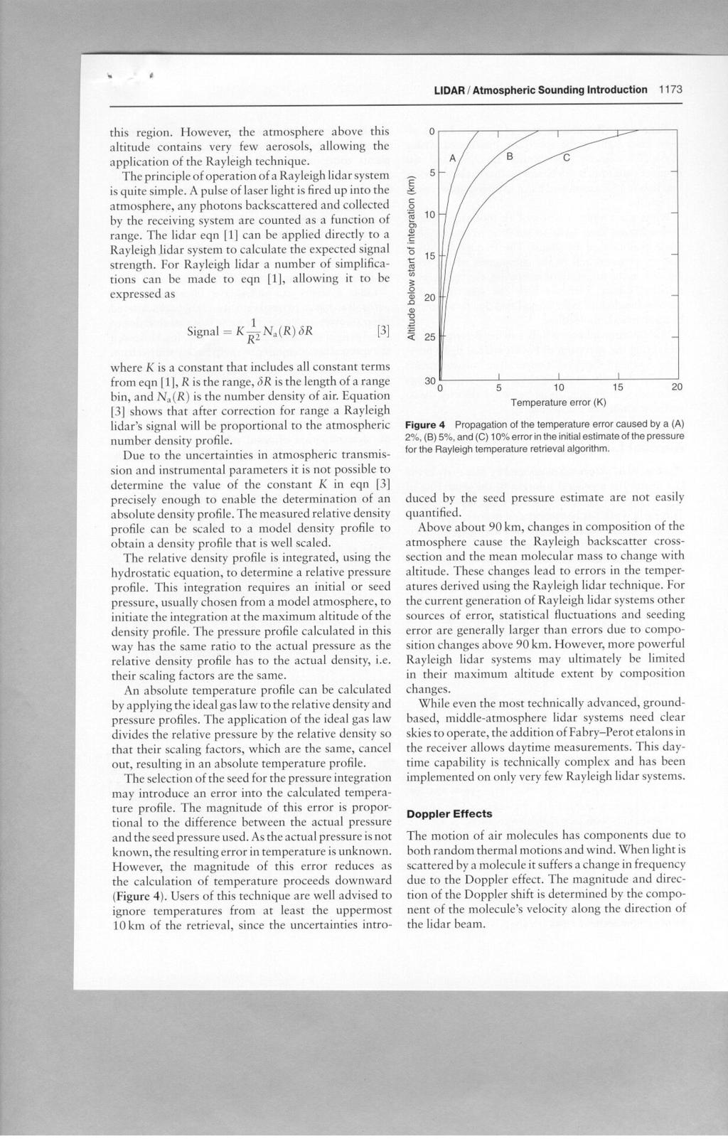
4 ~.,; 1172 LIDAR / Atmospheric Sounding Introduction Coherent Detection There is a class of lidar systems that determine wind speed by measuring the Doppler shift of backscattered light. There are two ways these measurements can be achieved, namely incoherent and coherent detection. Incoherent systems measure the wavelength of the transmitted and received light independently, using a spectrometer, and determine the Doppler shift from these two measurements. Coherent detection systems use a local oscillator, a narrow-band continuous-wave laser, to set the frequency of the transmitted pulses. Systems incorporating coherent detection use a local oscillator on a photomixer. This arrangement results in the output of the photomixer being a radiofrequency (RF) signal whose frequency is the difference of the frequencies of the local oscillator and the backscattered light. Standard RF techniques are then used to measure and record this RF signal. The measured RF signal is used to determine the Doppler shift of the backscattered light and thus the wind speed. The Lidar Equation The lidar equation is used to determine the number of photons detected by a lidar system. The lidar equation takes into account both instrumental parameters and geophysical variables. The general form of the lidar equation includes all forms of scattering and it can be used to calculate the signal strength for any lidar. The number of photons detected as pulses at the photomultiplier output, per laser pulse, is A r PS(A)Tt(A)Tr(A){2(A) J.1.)' do'. xl ~ (A)Nj(r) drda I [1] In eqn [1] A is the area of the telescope; PS(A) is the convolutionofp(a) ands(a), wherep(a) is the number of photons emitted by the laser in a single laser pulse and S(A) is a function which takes into account any wavelength shift during scattering, including Doppler and Raman shifts; LlA is the wavelength range for which PS(A) is nonzero; 't"t(a) and 't"r(a) are the optical transmission coefficients of the transmitter and receiver optics respectively; Q(A) is the quantum efficiency of the photomultiplier; r is the range and R 1 and R2 are the minimum and maximum ranges for a range bin; ~ (A) is the overlap factor which takes into account the intensity distribution across the laser beam and the physical overlap of the transmitted laser beam and the field of view of the receiver optics; 't"a(r, A) is the optical transmission of the atmosphere along the laser path; (do";/dq)(a) is the backscatter cross-section for scattering of type i; and Nj(r) is the number density of scattering centers, which cause scattering of type i. The general form of the tidar equation, as expressed in eqn [1], can usually be greatly simplified when applied to a particular lidar system. Rayleigh Lidar Rayleigh lidar is the name given to the class of lidar systems that measure the intensity of light backscatter by molecules from altitudes between about 30 and 100 km. The intensity profiles measured by Rayleigh lidars are used to calculate relative density profiles, which are in turn used to calculate absolute temperature profiles. The terms Rayleigh scattering and molecular scattering are often used interchangeably, as are the terms Mie scattering and aerosol scattering. Rayleigh theory named after its founder, Lord Rayleigh, describes the scattering of light by molecules that are small compared with the wavelength of the incident radiation; Mie theory describes scattering by aerosols that are not small compared with the wavelength, so there is a strong connection between these two pairs of terms. Rayleigh scattering explains the color, intensity distribution, and polarization of the blue sky in terms of scattering by atmospheric molecules. For objects with dimensions greater than about times the incident wavelength, the more general Mie theory must be used to calculate scattering effects. The Rayleigh backscatter (0 = n) cross-section for the atmosphere below 90 km can be expressed as dur(o = 1t) - C m2 sr-l dq - l4 [2] where the value of C is between about 4.75 x to-57 and 5.00 x to-57, depending on the value used for index of refraction of air. Above 90 km altitude, the concentration of atomic oxygen becomes significant, causing the refractive index of air to change, resulting in eqn [2] becoming less accurate with increasing altitude. The Rayleigh backscatter cross-section, eqn [2], can be used in conjunction with the lidar eqn [1] to determine the intensity of the backscatter that can be expected for a particular Rayleigh lidar system. The Rayleigh lidar technique relies on the measured signal being proportional to the atmospheric density. This is not the case in any region that contains aerosols. From the surface to the top of the stratospheric aerosol layer, about km, the atmosphere contains a significant concentration of aerosols, thus the Rayleigh technique cannot be directly applied to
5
6
7
8
Lecture 03. Lidar Remote Sensing Overview (1)
") Lecture 03. Lidar Remote Sensing Overview (1) Introduction History from searchlight to modern lidar Various modern lidars Altitude/Range determination Basic lidar architecture Summary Introduction: Lidar
Lecture 03. Lidar Remote Sensing Overview (1) Introduction History from searchlight to modern lidar Various modern lidars Altitude/Range determination Basic lidar architecture Summary Introduction: Lidar
Lecture 02. Introduction of Remote Sensing
 Lecture 02. Introduction of Remote Sensing Concept of Remote Sensing Picture of Remote Sensing Content of Remote Sensing Classification of Remote Sensing Passive Remote Sensing Active Remote Sensing Comparison
Lecture 21. Wind Lidar (3) Direct Detection Doppler Lidar
 Direct Detection Doppler Lidar") Lecture 21. Wind Lidar (3) Direct Detection Doppler Lidar Overview of Direct Detection Doppler Lidar (DDL) Resonance fluorescence DDL Fringe imaging DDL Scanning FPI DDL FPI edge-filter DDL Absorption
Lecture 21. Wind Lidar (3) Direct Detection Doppler Lidar Overview of Direct Detection Doppler Lidar (DDL) Resonance fluorescence DDL Fringe imaging DDL Scanning FPI DDL FPI edge-filter DDL Absorption
Lecture 27. Wind Lidar (6) Edge Filter-Based Direct Detection Doppler Lidar
 Edge Filter-Based Direct Detection Doppler Lidar") Lecture 27. Wind Lidar (6) Edge Filter-Based Direct Detection Doppler Lidar q FPI and Fizeau edge-filter DDL q Iodine-absorption-line edge-filter DDL q Edge-filter lidar data retrieval and error analysis
Lecture 27. Wind Lidar (6) Edge Filter-Based Direct Detection Doppler Lidar q FPI and Fizeau edge-filter DDL q Iodine-absorption-line edge-filter DDL q Edge-filter lidar data retrieval and error analysis
Lecture 36. Lidar Architecture and Lidar Design
 Lecture 36. Lidar Architecture and Lidar Design q Introduction q Lidar Architecture: Configurations & Arrangements q Lidar Design: Basic Ideas and Basic Principles q Considerations on Various Aspects of
Lecture 08. Fundamentals of Lidar Remote Sensing (6)
") Lecture 08. Fundamentals of Lidar Remote Sensing (6) Basic Lidar Architecture q Basic Lidar Architecture q Configurations vs. Arrangements q Transceiver with HOE q A real example: STAR Na Doppler Lidar
Lecture 08. Fundamentals of Lidar Remote Sensing (6) Basic Lidar Architecture q Basic Lidar Architecture q Configurations vs. Arrangements q Transceiver with HOE q A real example: STAR Na Doppler Lidar
Applications of Optics
 Nicholas J. Giordano www.cengage.com/physics/giordano Chapter 26 Applications of Optics Marilyn Akins, PhD Broome Community College Applications of Optics Many devices are based on the principles of optics
Lecture 25. Wind Lidar (3) Direct Detection Doppler Lidar
 Direct Detection Doppler Lidar") Lecture 25. Wind Lidar (3) Direct Detection Doppler Lidar Overview of Direct Detection Doppler Lidar (DDL) Fringe imaging DDL Scanning FPI DDL FPI edge-filter DDL Iodine absorption-line edge-filter DDL
Lecture 25. Wind Lidar (3) Direct Detection Doppler Lidar Overview of Direct Detection Doppler Lidar (DDL) Fringe imaging DDL Scanning FPI DDL FPI edge-filter DDL Iodine absorption-line edge-filter DDL
Introduction. Laser Diodes. Chapter 12 Laser Communications
 Chapter 1 Laser Communications A key technology to enabling small spacecraft missions is a lightweight means of communication. Laser based communications provides many benefits that make it attractive
Lecture 08. Fundamentals of Lidar Remote Sensing (6)
") Lecture 08. Fundamentals of Lidar Remote Sensing (6) Basic Lidar Architecture Basic Lidar Architecture Configurations vs. Arrangements Transceiver with HOE A real example: STAR Na Doppler Lidar Another
Lecture 08. Fundamentals of Lidar Remote Sensing (6) Basic Lidar Architecture Basic Lidar Architecture Configurations vs. Arrangements Transceiver with HOE A real example: STAR Na Doppler Lidar Another
Spatially Resolved Backscatter Ceilometer
 Spatially Resolved Backscatter Ceilometer Design Team Hiba Fareed, Nicholas Paradiso, Evan Perillo, Michael Tahan Design Advisor Prof. Gregory Kowalski Sponsor, Spectral Sciences Inc. Steve Richstmeier,
Receiver Signal to Noise Ratios for IPDA Lidars Using Sine-wave and Pulsed Laser Modulation and Direct Detections
 Receiver Signal to Noise Ratios for IPDA Lidars Using Sine-wave and Pulsed Laser Modulation and Direct Detections Xiaoli Sun and James B. Abshire NASA Goddard Space Flight Center Solar System Division,
Optical Remote Sensing with Coherent Doppler Lidar
 Optical Remote Sensing with Coherent Doppler Lidar Part 1: Background and Doppler Lidar Hardware Mike Hardesty 1, Sara Tucker 2, Alan Brewer 1 1 CIRES-NOAA Atmospheric Remote Sensing Group Earth System
Period 3 Solutions: Electromagnetic Waves Radiant Energy II
 Period 3 Solutions: Electromagnetic Waves Radiant Energy II 3.1 Applications of the Quantum Model of Radiant Energy 1) Photon Absorption and Emission 12/29/04 The diagrams below illustrate an atomic nucleus
Instruction manual and data sheet ipca h
 1/15 instruction manual ipca-21-05-1000-800-h Instruction manual and data sheet ipca-21-05-1000-800-h Broad area interdigital photoconductive THz antenna with microlens array and hyperhemispherical silicon
DIFFERENTIAL ABSORPTION LIDAR FOR GREENHOUSE GAS MEASUREMENTS
 DIFFERENTIAL ABSORPTION LIDAR FOR GREENHOUSE GAS MEASUREMENTS Stephen E. Maxwell, Sensor Science Division, PML Kevin O. Douglass, David F. Plusquellic, Radiation and Biomolecular Physics Division, PML
CONFIGURING. Your Spectroscopy System For PEAK PERFORMANCE. A guide to selecting the best Spectrometers, Sources, and Detectors for your application
 CONFIGURING Your Spectroscopy System For PEAK PERFORMANCE A guide to selecting the best Spectrometers, s, and s for your application Spectral Measurement System Spectral Measurement System Spectrograph
Lecture 9: Raman lidar
 Lecture 9: Raman lidar Water vapor mixing ratio measured by the SRL during the dryline event. Temporal resolution is 3 minutes, vertical smoothing varied between 90 meters at 0.5 km to 330 meters
Coherent Receivers Principles Downconversion
 Coherent Receivers Principles Downconversion Heterodyne receivers mix signals of different frequency; if two such signals are added together, they beat against each other. The resulting signal contains
Optical Fiber. n 2. n 1. θ 2. θ 1. Critical Angle According to Snell s Law
 ECE 271 Week 10 Critical Angle According to Snell s Law n 1 sin θ 1 = n 1 sin θ 2 θ 1 and θ 2 are angle of incidences The angle of incidence is measured with respect to the normal at the refractive boundary
SODAR- sonic detecting and ranging
 Active Remote Sensing of the PBL Immersed vs. remote sensors Active vs. passive sensors RADAR- radio detection and ranging WSR-88D TDWR wind profiler SODAR- sonic detecting and ranging minisodar RASS RADAR
1.6 Beam Wander vs. Image Jitter
 8 Chapter 1 1.6 Beam Wander vs. Image Jitter It is common at this point to look at beam wander and image jitter and ask what differentiates them. Consider a cooperative optical communication system that
NSOM (SNOM) Overview
 Overview") NSOM (SNOM) Overview The limits of far field imaging In the early 1870s, Ernst Abbe formulated a rigorous criterion for being able to resolve two objects in a light microscope: d > ë / (2sinè) where d
NSOM (SNOM) Overview The limits of far field imaging In the early 1870s, Ernst Abbe formulated a rigorous criterion for being able to resolve two objects in a light microscope: d > ë / (2sinè) where d
combustion diagnostics
 3. Instrumentation t ti for optical combustion diagnostics Equipment for combustion laser diagnostics 1) Laser/Laser system 2) Optics Lenses Polarizer Filters Mirrors Etc. 3) Detector CCD-camera Spectrometer
Applications of Steady-state Multichannel Spectroscopy in the Visible and NIR Spectral Region
 Feature Article JY Division I nformation Optical Spectroscopy Applications of Steady-state Multichannel Spectroscopy in the Visible and NIR Spectral Region Raymond Pini, Salvatore Atzeni Abstract Multichannel
Absorption: in an OF, the loss of Optical power, resulting from conversion of that power into heat.
 Absorption: in an OF, the loss of Optical power, resulting from conversion of that power into heat. Scattering: The changes in direction of light confined within an OF, occurring due to imperfection in
G1 THE NATURE OF EM WAVES AND LIGHT SOURCES
 G1 THE NATURE OF EM WAVES AND LIGHT SOURCES G2 OPTICAL INSTRUMENTS HW/Study Packet Required: READ Tsokos, pp 598-620 SL/HL Supplemental: Hamper, pp 411-450 DO Questions p 605 #1,3 pp 621-623 #6,8,15,18,19,24,26
Passive Microwave Sensors LIDAR Remote Sensing Laser Altimetry. 28 April 2003
 Passive Microwave Sensors LIDAR Remote Sensing Laser Altimetry 28 April 2003 Outline Passive Microwave Radiometry Rayleigh-Jeans approximation Brightness temperature Emissivity and dielectric constant
FOR 353: Air Photo Interpretation and Photogrammetry. Lecture 2. Electromagnetic Energy/Camera and Film characteristics
 FOR 353: Air Photo Interpretation and Photogrammetry Lecture 2 Electromagnetic Energy/Camera and Film characteristics Lecture Outline Electromagnetic Radiation Theory Digital vs. Analog (i.e. film ) Systems
Spectroscopy in the UV and Visible: Instrumentation. Spectroscopy in the UV and Visible: Instrumentation
 Spectroscopy in the UV and Visible: Instrumentation Typical UV-VIS instrument 1 Source - Disperser Sample (Blank) Detector Readout Monitor the relative response of the sample signal to the blank Transmittance
Observational Astronomy
 Observational Astronomy Instruments The telescope- instruments combination forms a tightly coupled system: Telescope = collecting photons and forming an image Instruments = registering and analyzing the
Spectral phase shaping for high resolution CARS spectroscopy around 3000 cm 1
 Spectral phase shaping for high resolution CARS spectroscopy around 3 cm A.C.W. van Rhijn, S. Postma, J.P. Korterik, J.L. Herek, and H.L. Offerhaus Mesa + Research Institute for Nanotechnology, University
Spectrophotometer. An instrument used to make absorbance, transmittance or emission measurements is known as a spectrophotometer :
 Spectrophotometer An instrument used to make absorbance, transmittance or emission measurements is known as a spectrophotometer : Spectrophotometer components Excitation sources Deuterium Lamp Tungsten
Range Dependent Turbulence Characterization by Co-operating Coherent Doppler Lidar with Direct Detection Lidar
 Range Dependent Turbulence Characterization by Co-operating Coherent Doppler idar with Direct Detection idar Sameh Abdelazim(a), David Santoro(b), Mark Arend(b), Sam Ahmed(b), and Fred Moshary(b) (a)fairleigh
Photonics and Fiber Optics
 1 UNIT V Photonics and Fiber Optics Part-A 1. What is laser? LASER is the acronym for Light Amplification by Stimulated Emission of Radiation. The absorption and emission of light by materials has been
LlIGHT REVIEW PART 2 DOWNLOAD, PRINT and submit for 100 points
 WRITE ON SCANTRON WITH NUMBER 2 PENCIL DO NOT WRITE ON THIS TEST LlIGHT REVIEW PART 2 DOWNLOAD, PRINT and submit for 100 points Multiple Choice Identify the choice that best completes the statement or
Deliverable D20.2: Report on evaluation of Raman lidar techniques for daytime extinction measurements
 WP JRA: Lidar and sunphotometer Improved instruments, integrated observations and combined algorithms Deliverable D.: Report on evaluation of Raman lidar techniques for daytime extinction measurements
Examination Optoelectronic Communication Technology. April 11, Name: Student ID number: OCT1 1: OCT 2: OCT 3: OCT 4: Total: Grade:
 Examination Optoelectronic Communication Technology April, 26 Name: Student ID number: OCT : OCT 2: OCT 3: OCT 4: Total: Grade: Declaration of Consent I hereby agree to have my exam results published on
CONFOCAL FABRY-PEROT INTERFEROMETER BASED HIGH SPECTRAL RESOLUTION LIDAR. David Swick Hoffman
 CONFOCAL FABRY-PEROT INTERFEROMETER BASED HIGH SPECTRAL RESOLUTION LIDAR by David Swick Hoffman A dissertation submitted in partial fulfillment of the requirements for the degree of Doctor of Philosophy
Uses of Electromagnetic Waves
 Uses of Electromagnetic Waves 1 of 42 Boardworks Ltd 2016 Uses of Electromagnetic Waves 2 of 42 Boardworks Ltd 2016 What are radio waves? 3 of 42 Boardworks Ltd 2016 The broadcast of every radio and television
Chapter 23 Study Questions Name: Class:
 Chapter 23 Study Questions Name: Class: Multiple Choice Identify the letter of the choice that best completes the statement or answers the question. 1. When you look at yourself in a plane mirror, you
Human Retina. Sharp Spot: Fovea Blind Spot: Optic Nerve
 I am Watching YOU!! Human Retina Sharp Spot: Fovea Blind Spot: Optic Nerve Human Vision Optical Antennae: Rods & Cones Rods: Intensity Cones: Color Energy of Light 6 10 ev 10 ev 4 1 2eV 40eV KeV MeV Energy
The absorption of the light may be intrinsic or extrinsic
 Attenuation Fiber Attenuation Types 1- Material Absorption losses 2- Intrinsic Absorption 3- Extrinsic Absorption 4- Scattering losses (Linear and nonlinear) 5- Bending Losses (Micro & Macro) Material
The below identified patent application is available for licensing. Requests for information should be addressed to:
 DEPARTMENT OF THE NAVY OFFICE OF COUNSEL NAVAL UNDERSEA WARFARE CENTER DIVISION 1176 HOWELL STREET NEWPORT Rl 0841-1708 IN REPLY REFER TO Attorney Docket No. 300048 7 February 017 The below identified
Ground-based optical auroral measurements
 Ground-based optical auroral measurements FYS 3610 Background Ground-based optical measurements provides a unique way to monitor spatial and temporal variation of auroral activity at high resolution up
Compact Ozone Differential Absorption Lidar (DIAL) Transmitter Using Solid-State Dye Polymers
 Transmitter Using Solid-State Dye Polymers") NASA/TM-21-21128 Compact Ozone Differential Absorption Lidar (DIAL) Transmitter Using Solid-State Dye Polymers Alton L. Jones, Jr. Old Dominion University, Norfolk, Virginia Russell J. DeYoung Langley
NASA/TM-21-21128 Compact Ozone Differential Absorption Lidar (DIAL) Transmitter Using Solid-State Dye Polymers Alton L. Jones, Jr. Old Dominion University, Norfolk, Virginia Russell J. DeYoung Langley
Page 1. Ground-based optical auroral measurements. Background. CCD All-sky Camera with filterwheel. Image intensifier
 Ground-based optical auroral measurements FYS 3610 Background Ground-based optical measurements provides a unique way to monitor spatial and temporal variation of auroral activity at high resolution up
Receiver Performance and Comparison of Incoherent (bolometer) and Coherent (receiver) detection
 and Coherent (receiver) detection") At ev gap /h the photons have sufficient energy to break the Cooper pairs and the SIS performance degrades. Receiver Performance and Comparison of Incoherent (bolometer) and Coherent (receiver) detection
At ev gap /h the photons have sufficient energy to break the Cooper pairs and the SIS performance degrades. Receiver Performance and Comparison of Incoherent (bolometer) and Coherent (receiver) detection
Light, Lasers, and Holograms Teleclass Webinar!
 Welcome to the Supercharged Science Light, Lasers, and Holograms Teleclass Webinar! You can fill out this worksheet as we go along to get the most out of time together, or you can use it as a review exercise
Use of a Hybrid Photo Detector (HPD) in the MAGIC micro power LIDAR system
 in the MAGIC micro power LIDAR system") Use of a Hybrid Photo Detector (HPD) in the MAGIC micro power LIDAR system Christian Fruck cfruck@ph.tum.de Max-Planck-Institut für Physik LIGHT 11 - Ringberg 03.11.2011 1 / 18 Overview MAGIC uses the
Use of a Hybrid Photo Detector (HPD) in the MAGIC micro power LIDAR system Christian Fruck cfruck@ph.tum.de Max-Planck-Institut für Physik LIGHT 11 - Ringberg 03.11.2011 1 / 18 Overview MAGIC uses the
746A27 Remote Sensing and GIS
 746A27 Remote Sensing and GIS Lecture 1 Concepts of remote sensing and Basic principle of Photogrammetry Chandan Roy Guest Lecturer Department of Computer and Information Science Linköping University What
Electromagnetic Waves
 Electromagnetic Waves What is an Electromagnetic Wave? An EM Wave is a disturbance that transfers energy through a field. A field is a area around an object where the object can apply a force on another
Laser Telemetric System (Metrology)
") Laser Telemetric System (Metrology) Laser telemetric system is a non-contact gauge that measures with a collimated laser beam (Refer Fig. 10.26). It measure at the rate of 150 scans per second. It basically
Laser Telemetric System (Metrology) Laser telemetric system is a non-contact gauge that measures with a collimated laser beam (Refer Fig. 10.26). It measure at the rate of 150 scans per second. It basically
LTE. Tester of laser range finders. Integrator Target slider. Transmitter channel. Receiver channel. Target slider Attenuator 2
 a) b) External Attenuators Transmitter LRF Receiver Transmitter channel Receiver channel Integrator Target slider Target slider Attenuator 2 Attenuator 1 Detector Light source Pulse gene rator Fiber attenuator
Quantum frequency standard Priority: Filing: Grant: Publication: Description
 C Quantum frequency standard Inventors: A.K.Dmitriev, M.G.Gurov, S.M.Kobtsev, A.V.Ivanenko. Priority: 2010-01-11 Filing: 2010-01-11 Grant: 2011-08-10 Publication: 2011-08-10 Description The present invention
Submillimeter (continued)
") Submillimeter (continued) Dual Polarization, Sideband Separating Receiver Dual Mixer Unit The 12-m Receiver Here is where the receiver lives, at the telescope focus Receiver Performance T N (noise temperature)
Submillimeter (continued) Dual Polarization, Sideband Separating Receiver Dual Mixer Unit The 12-m Receiver Here is where the receiver lives, at the telescope focus Receiver Performance T N (noise temperature)
Laser Beam Analysis Using Image Processing
 Journal of Computer Science 2 (): 09-3, 2006 ISSN 549-3636 Science Publications, 2006 Laser Beam Analysis Using Image Processing Yas A. Alsultanny Computer Science Department, Amman Arab University for
Fiberoptic and Waveguide Sensors
 Fiberoptic and Waveguide Sensors Wei-Chih Wang Department of Mecahnical Engineering University of Washington Optical sensors Advantages: -immune from electromagnetic field interference (EMI) - extreme
LE/ESSE Payload Design
 LE/ESSE4360 - Payload Design 3.2 Spacecraft Sensors Introduction to Sensors Earth, Moon, Mars, and Beyond Dr. Jinjun Shan, Professor of Space Engineering Department of Earth and Space Science and Engineering
PHYS 202 OUTLINE FOR PART III LIGHT & OPTICS
 PHYS 202 OUTLINE FOR PART III LIGHT & OPTICS Electromagnetic Waves A. Electromagnetic waves S-23,24 1. speed of waves = 1/( o o ) ½ = 3 x 10 8 m/s = c 2. waves and frequency: the spectrum (a) radio red
SodiumStar 20/2 High Power cw Tunable Guide Star Laser
 SodiumStar 20/2 High Power cw Tunable Guide Star Laser Laser Guide Star Adaptive Optics Facilities LIDAR Atmospheric Monitoring Laser Cooling SodiumStar 20/2 High Power cw Tunable Guide Star Laser Existing
Optical Fiber Technology. Photonic Network By Dr. M H Zaidi
 Optical Fiber Technology Numerical Aperture (NA) What is numerical aperture (NA)? Numerical aperture is the measure of the light gathering ability of optical fiber The higher the NA, the larger the core
Subsystems of Radar and Signal Processing and ST Radar
 Advance in Electronic and Electric Engineering. ISSN 2231-1297, Volume 3, Number 5 (2013), pp. 531-538 Research India Publications http://www.ripublication.com/aeee.htm Subsystems of Radar and Signal Processing
NGSLR's measurement of the retro-reflector array response of various LEO to GNSS satellites
 NGSLR's measurement of the retro-reflector array response of various LEO to GNSS satellites Jan McGarry Christopher Clarke, John Degnan, Howard Donovan, Benjamin Han, Julie Horvath, Thomas Zagwodzki NASA/GSFC
Lasers PH 645/ OSE 645/ EE 613 Summer 2010 Section 1: T/Th 2:45-4:45 PM Engineering Building 240
 Lasers PH 645/ OSE 645/ EE 613 Summer 2010 Section 1: T/Th 2:45-4:45 PM Engineering Building 240 John D. Williams, Ph.D. Department of Electrical and Computer Engineering 406 Optics Building - UAHuntsville,
Chapter Ray and Wave Optics
 109 Chapter Ray and Wave Optics 1. An astronomical telescope has a large aperture to [2002] reduce spherical aberration have high resolution increase span of observation have low dispersion. 2. If two
Lecture Outlines Chapter 25. Physics, 3 rd Edition James S. Walker
 Lecture Outlines Chapter 25 Physics, 3 rd Edition James S. Walker 2007 Pearson Prentice Hall This work is protected by United States copyright laws and is provided solely for the use of instructors in
Lecture 15: Fraunhofer diffraction by a circular aperture
 Lecture 15: Fraunhofer diffraction by a circular aperture Lecture aims to explain: 1. Diffraction problem for a circular aperture 2. Diffraction pattern produced by a circular aperture, Airy rings 3. Importance
EE119 Introduction to Optical Engineering Spring 2003 Final Exam. Name:
 EE119 Introduction to Optical Engineering Spring 2003 Final Exam Name: SID: CLOSED BOOK. THREE 8 1/2 X 11 SHEETS OF NOTES, AND SCIENTIFIC POCKET CALCULATOR PERMITTED. TIME ALLOTTED: 180 MINUTES Fundamental
Chemistry 524--"Hour Exam"--Keiderling Mar. 19, pm SES
 Chemistry 524--"Hour Exam"--Keiderling Mar. 19, 2013 -- 2-4 pm -- 170 SES Please answer all questions in the answer book provided. Calculators, rulers, pens and pencils permitted. No open books allowed.
P1.1 THE DEVELOPMENT OF THE HOWARD UNIVERSITY RAMAN LIDAR
 P1.1 THE DEVEOPMET OF THE HOWARD UIVERSITY RAMA IDAR Demetrius Venable 1,*, Everette Joseph 1, David Whiteman 2, Belay Demo 2, Rasheen Connell 1, and Segayle Walford 1 1 Howard University, Washington,
SYLLABUS Optical Fiber Communication
 SYLLABUS Optical Fiber Communication Subject Code : IA Marks : 25 No. of Lecture Hrs/Week : 04 Exam Hours : 03 Total no. of Lecture Hrs. : 52 Exam Marks : 100 UNIT - 1 PART - A OVERVIEW OF OPTICAL FIBER
CHAPTER 7. Components of Optical Instruments
 CHAPTER 7 Components of Optical Instruments From: Principles of Instrumental Analysis, 6 th Edition, Holler, Skoog and Crouch. CMY 383 Dr Tim Laurens NB Optical in this case refers not only to the visible
FPPO 1000 Fiber Laser Pumped Optical Parametric Oscillator: FPPO 1000 Product Manual
 Fiber Laser Pumped Optical Parametric Oscillator: FPPO 1000 Product Manual 2012 858 West Park Street, Eugene, OR 97401 www.mtinstruments.com Table of Contents Specifications and Overview... 1 General Layout...
Multi-wavelength aerosol LIDAR signal preprocessing:
 IOP Conference Series: Earth and Environmental Science PAPER OPEN ACCESS Multi-wavelength aerosol LIDAR signal preprocessing: practical considerations To cite this article: A Rodríguez-Gómez et al 15 IOP
Chapter 25. Optical Instruments
 Chapter 25 Optical Instruments Optical Instruments Analysis generally involves the laws of reflection and refraction Analysis uses the procedures of geometric optics To explain certain phenomena, the wave
Chapter 16 Light Waves and Color
 Chapter 16 Light Waves and Color Lecture PowerPoint Copyright The McGraw-Hill Companies, Inc. Permission required for reproduction or display. What causes color? What causes reflection? What causes color?
Optics & Light. See What I m Talking About. Grade 8 - Science OPTICS - GRADE 8 SCIENCE 1
 Optics & Light See What I m Talking About Grade 8 - Science OPTICS - GRADE 8 SCIENCE 1 Overview In this cluster, students broaden their understanding of how light is produced, transmitted, and detected.
Topic 1 - What is Light? 1. Radiation is the type of energy transfer which does not require... A matter B heat C waves D light
 Grade 8 Unit 1 Test Student Class Topic 1 - What is Light? 1. Radiation is the type of energy transfer which does not require... A matter B heat C waves D light 2. Light-producing technologies, such as
Optical Through-the-Air Communications Handbook -David A. Johnson, Figure 6p
 Optical Through-the-Air Communications Handbook -David A. Johnson, Figure 6p Optical Through-the-Air Communications Handbook -David A. Johnson, Figure 6o Optical Through-the-Air Communications Handbook
6.014 Recitation 1: Wireless Radio and Optical Links
 6.014 Recitation 1: Wireless Radio and Optical Links A. Review Wireless radio links were introduced in Lecture 1. The basic equations introduced there are repeated in Figure R1-1 and below. First is the
Radar. Seminar report. Submitted in partial fulfillment of the requirement for the award of degree Of Mechanical
 A Seminar report on Radar Submitted in partial fulfillment of the requirement for the award of degree Of Mechanical SUBMITTED TO: SUBMITTED BY: www.studymafia.org www.studymafia.org Preface I have made
B. Cavity-Enhanced Absorption Spectroscopy (CEAS)
") B. Cavity-Enhanced Absorption Spectroscopy (CEAS) CEAS is also known as ICOS (integrated cavity output spectroscopy). Developed in 1998 (Engeln et al.; O Keefe et al.) In cavity ringdown spectroscopy,
B. Cavity-Enhanced Absorption Spectroscopy (CEAS) CEAS is also known as ICOS (integrated cavity output spectroscopy). Developed in 1998 (Engeln et al.; O Keefe et al.) In cavity ringdown spectroscopy,
R. J. Jones Optical Sciences OPTI 511L Fall 2017
 R. J. Jones Optical Sciences OPTI 511L Fall 2017 Semiconductor Lasers (2 weeks) Semiconductor (diode) lasers are by far the most widely used lasers today. Their small size and properties of the light output
Transmitting Light: Fiber-optic and Free-space Communications Holography
 1 Lecture 9 Transmitting Light: Fiber-optic and Free-space Communications Holography 2 Wireless Phone Calls http://havilandtelconews.com/2011/10/the-reality-behind-wireless-networks/ 3 Undersea Cable and
TSBB09 Image Sensors 2018-HT2. Image Formation Part 1
 TSBB09 Image Sensors 2018-HT2 Image Formation Part 1 Basic physics Electromagnetic radiation consists of electromagnetic waves With energy That propagate through space The waves consist of transversal
Light has some interesting properties, many of which are used in medicine:
 LIGHT IN MEDICINE Light has some interesting properties, many of which are used in medicine: 1- The speed of light changes when it goes from one material into another. The ratio of the speed of light in
Picosecond Time Analyzer Applications in...
 ORTEC AN52 Picosecond Time Analyzer Applications in... LIDAR and DIAL Time-of-Flight Mass Spectrometry Fluorescence/Phosphorescence Lifetime Spectrometry Pulse or Signal Jitter Analysis CONTENTS of this
X-ray generation by femtosecond laser pulses and its application to soft X-ray imaging microscope
 X-ray generation by femtosecond laser pulses and its application to soft X-ray imaging microscope Kenichi Ikeda 1, Hideyuki Kotaki 1 ' 2 and Kazuhisa Nakajima 1 ' 2 ' 3 1 Graduate University for Advanced
Doppler-Free Spetroscopy of Rubidium
 Doppler-Free Spetroscopy of Rubidium Pranjal Vachaspati, Sabrina Pasterski MIT Department of Physics (Dated: April 17, 2013) We present a technique for spectroscopy of rubidium that eliminates doppler
Eye safe solid state lasers for remote sensing and coherent laser radar
 Eye safe solid state lasers for remote sensing and coherent laser radar Jesper Munch, Matthew Heintze, Murray Hamilton, Sean Manning, Y. Mao, Damien Mudge and Peter Veitch Department of Physics The University
Physics 431 Final Exam Examples (3:00-5:00 pm 12/16/2009) TIME ALLOTTED: 120 MINUTES Name: Signature:
 TIME ALLOTTED: 120 MINUTES Name: Signature:") Physics 431 Final Exam Examples (3:00-5:00 pm 12/16/2009) TIME ALLOTTED: 120 MINUTES Name: PID: Signature: CLOSED BOOK. TWO 8 1/2 X 11 SHEET OF NOTES (double sided is allowed), AND SCIENTIFIC POCKET CALCULATOR
Physics 431 Final Exam Examples (3:00-5:00 pm 12/16/2009) TIME ALLOTTED: 120 MINUTES Name: PID: Signature: CLOSED BOOK. TWO 8 1/2 X 11 SHEET OF NOTES (double sided is allowed), AND SCIENTIFIC POCKET CALCULATOR
Simulative Analysis of 10 Gbps High Speed Free Space Optical Communication Link
 , pp. 139-144 http://dx.doi.org/10.14257/ijfgcn.2016.9.3.13 Simulative Analysis of 10 Gbps High Speed Free Space Optical Communication Link Mehtab Singh ECE Department Satyam Institute of Engineering and
PROJECT REPORT COUPLING OF LIGHT THROUGH FIBER PHY 564 SUBMITTED BY: GAGANDEEP KAUR ( )
") PROJECT REPORT COUPLING OF LIGHT THROUGH FIBER PHY 564 SUBMITTED BY: GAGANDEEP KAUR (952549116) 1 INTRODUCTION: An optical fiber (or fiber) is a glass or plastic fiber that carries light along its length.
PROJECT REPORT COUPLING OF LIGHT THROUGH FIBER PHY 564 SUBMITTED BY: GAGANDEEP KAUR (952549116) 1 INTRODUCTION: An optical fiber (or fiber) is a glass or plastic fiber that carries light along its length.
Lecture Notes Prepared by Prof. J. Francis Spring Remote Sensing Instruments
 Lecture Notes Prepared by Prof. J. Francis Spring 2005 Remote Sensing Instruments Material from Remote Sensing Instrumentation in Weather Satellites: Systems, Data, and Environmental Applications by Rao,
Microwave and optical systems Introduction p. 1 Characteristics of waves p. 1 The electromagnetic spectrum p. 3 History and uses of microwaves and
 Microwave and optical systems Introduction p. 1 Characteristics of waves p. 1 The electromagnetic spectrum p. 3 History and uses of microwaves and optics p. 4 Communication systems p. 6 Radar systems p.
INTRODUCTION THIN LENSES. Introduction. given by the paraxial refraction equation derived last lecture: Thin lenses (19.1) = 1. Double-lens systems
 = 1. Double-lens systems") Chapter 9 OPTICAL INSTRUMENTS Introduction Thin lenses Double-lens systems Aberrations Camera Human eye Compound microscope Summary INTRODUCTION Knowledge of geometrical optics, diffraction and interference,
Chapter 9 OPTICAL INSTRUMENTS Introduction Thin lenses Double-lens systems Aberrations Camera Human eye Compound microscope Summary INTRODUCTION Knowledge of geometrical optics, diffraction and interference,
Status of Aeolus ESA s Wind Lidar Mission
 Status of Aeolus ESA s Wind Lidar Mission Roland Meynart, Anders Elfving, Denny Wernham and Anne Grete Straume European Space Agency/ESTEC Coherent Laser Radar Conference, Boulder 26 June-01 July 2016
Optical Communications and Networking 朱祖勍. Sept. 25, 2017
 Optical Communications and Networking Sept. 25, 2017 Lecture 4: Signal Propagation in Fiber 1 Nonlinear Effects The assumption of linearity may not always be valid. Nonlinear effects are all related to
Fiber Optic Communications
 Fiber Optic Communications ( Chapter 2: Optics Review ) presented by Prof. Kwang-Chun Ho 1 Section 2.4: Numerical Aperture Consider an optical receiver: where the diameter of photodetector surface area