Item ref: UK MTTR01 TRUE RMS DIGITAL MULTITESTER WITH USB INTERFACE. User Manual
|
|
|
- Gordon Tate
- 5 years ago
- Views:
Transcription


1 Item ref: UK MTTR01 TRUE RMS DIGITAL MULTITESTER WITH USB INTERFACE User Manual
2 Please read this manual thoroughly and ensure all contents are fully understood before using the apparatus. WARNING To avoid possible electric shock or personal injury, and to avoid possible damage to the tester or to the equipment under test, adhere to these following rules: Before using the tester inspect the case. Do not use the tester if it is damaged or the case (or part of the case) is removed. Look for cracks or missing plastic. Pay attention to the insulation around the connectors. Inspect the test leads for damaged insulation or exposed metal. Check the test leads for continuity. Do not apply more than the rated voltage, as marked on the tester, between the terminals or between any terminal and grounding. The rotary switch should be in the right position and no changeover of range shall be made while measurement is conducted to prevent damage. When the tester is working at an effective voltage over 60V in DC or 30Vrms in AC, special care should be taken for there is danger of electric shock. Use the proper terminals, function, and range for your measurements. Do not use or store the tester in an environment of high temperature, humidity, explosive, flammable, damp or of a strong magnetic field. The performance of the tester may deteriorate after being exposed to any of these elements. When using the test leads, keep your fingers behind the finger guards. Disconnect circuit power and discharge all high-voltage capacitors before testing resistance, continuity, diodes. Replace the battery as soon as the battery indicator appears. With a low battery, the meter may produce false readings that can lead to electric shock and personal injury.
3 Remove the connection between the testing leads and the circuit being tested, and turn the meter power off before opening the meter case. The internal circuit of the meter shall not be altered at will to avoid damage of the meter and any accident. A soft cloth and mild detergent should be used to clean the surface of the tester on a regular basis. No abrasive and solvent should be used to prevent the surface of the tester from corrosion or damage. The tester is suitable for indoor use only. Turn the tester power off when it is not in use and take out the battery when not using for a long time. Check the battery regularly; replace the battery immediately if any signs of leaking appear. Battery acid will damage the tester. General Specifications Max display: LCD (6000 count) 64 x 43mm Polarity: Automatic, indicated minus, assumed plus Measure method: double integral A/D switch implement Sampling speed: 2.5 times per second Over-load indication: OL is displayed Operating temperature: 0ºC to 40ºC, at <75%RH Storage temperature: -30ºC to 60ºC, at <85%RH Power: 9Vdc (1 x PP3 battery supplied) Low battery indication: Display resolution: 6000 counts Resistance: 600Ω to 60MΩ Capacitance: 40nF µF Frequency: 9.99Hz MHz Test temperature: -20 C C Duty cycle: 5% to 95% Dimensions: 188 x 81 x 48mm Weight: 420g (including battery)
4 Layout:
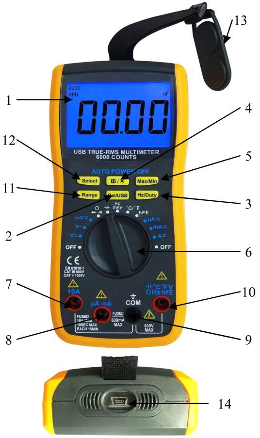
5 1. LCD Display, maximum reading of Relative and USB mode switch. Press to switch between auto reading mode auto and relative mode. Press and hold for 2 seconds to switch between USB mode USB and auto power off mode APO. 3. Hz/Duty display, when measuring AC voltage or current, press to display between the frequency and duty cycles of the measuring signals. 4. Press this button to data hold the display and press again to release data. Press and hold for 2 seconds to toggle the back light on for 10 seconds. 5. Max/Min Press this button to display the maximum and minimum reading from the moment this button is pressed. Press and hold this button for 2 seconds to exit Max/Min display mode. 6. Function/Range switch for selecting different measuring ranges and also serves as an ON/OFF switch. To preserve battery life, please ensure the range switch is turn to OFF position when not in use A Probe socket, socket for the positive (red) probe when measuring current between 400mA to 10A. 8. ua/ma Probe socket, socket for the positive (red) probe when measuring current below 400mA. 9. COM Probe socket, socket for the negative (black) probe. 10. Positive Probe socket, socket for the positive (red) probe for measuring everything apart from current. 11. Range switch, when measuring voltage, current, capacitance or resistance, pressing this button with disengage the auto range function and allow you to manually set the displaying range. 12. Select has following functions: - When measuring signal with combined AC+DC, pressing this button will allow the AC and DC to be measured separately. - To switch between measuring function of resistance, continuity and diode.

6 - To switch between displaying Fahrenheit and Celsius when measuring temperature. - Press and hold this button when switching the meter on to disable the auto power off function, this allows the meter to stay on standby unless manually switched off. 13. Strong magnet that allows meter to be attached to any iron/steel surface, in case both hands are required to take the measurement. 14. Mini USB socket at the bottom of the unit to connect to a PC. For testing transistors and capacitors, the measuring adaptor supplied should be connected as below. The two square sockets on the top are for testing capacitors and the 6 smaller sockets at the bottom are for testing the PNP and NPN type transistors.

7 LCD Display These signs and symbols indicate: 1. Duty cycle is selected 2. Temperature measurement is selected and measuring in Fahrenheit. 3. Temperature measurement is selected and measuring in Celsius. 4. Transistor testing mode is selected. 5. Continuity testing mode is selected, use Select button to choose between resistance measuring, diode testing and continuity testing. 6. Diode testing mode is selected, use Select button to choose between resistance measuring, diode testing and continuity testing. 7. Relative mode is selected, use Rel/USB button to select between auto range mode and relative mode. 8. USB mode is selected; meter is now sending live readings out through the USB output to connected PC. 9. Data hold, press to resume live reading. 10. Auto Range mode is selected, use Rel/USB button to select between auto range mode and relative mode. 11. Auto power off mode, meter will automatically switch off when it is not in use. 12. Displays the maximum reading from the moment the Max/Min function is enabled.
8 13. Displays the minimum reading from the moment the Max/Min function is enabled. 14. Currently measuring DC range. 15. Negative reading. 16. Currently measuring AC range. 17. Low battery indicator; replace battery immediately when this sign is shown to avoid false reading that may lead to electric shock. 18. Bar graph. The bar graph on the bottom of the LCD display is the analogue display of the reading when measuring voltage, current or resistance. The length of the bar is proportionate to the digital count above it. The bar graph has a sampling rate 10 times higher of the digital number display, this make it ideal for observing measurements with rapid changes. Technical Specifications This meter has been calibrated in the factory and accuracies of following are guaranteed for 1 year at 18ºC to 28ºC and less than 75% RH. DC Voltage RANGE RESOLUTION ACCURACY 60mV 10uV ± (1% of rdg + 7D) 600mV 0.1mV ± (0.8% of rdg + 5D) 6V 1mV 60V 10mV ± (0.5% of rdg + 5D) 600V 0.1V ± (0.8% of rdg + 5D) Input Impedance: >100MΩ for 60 and 600mV range, 10MΩ for 6, 60 and 600V. Overload Protection: 600V
9 AC Voltage RANGE RESOLUTION ACCURACY 60mV 10uV ± (2.0% of rdg + 10D) 600mV 0.1mV ± (1.6% of rdg + 10D) 6V 1mV 60V 10mV ± (1.5% of rdg + 10D) 600V 0.1V Input Impedance: >100MΩ for 60 and 600mV range, 10MΩ for 6, 60 and 600V. Frequency Range: 40Hz ~ 400Hz Overload Protection: 600Vrms Reading: True rms Max. Input voltage: 750Vac rms DC Current RANGE RESOLUTION ACCURACY Remark 600uA 0.1uA 6000uA 1uA ± (1.0% of rdg + 7D) 60mA 0.01mA Auto range 600mA 0.1mA 6A 1mA 10A 10mA ± (1.5% of rdg + 7D) Overload Protection: ma: F0.4A/600V fuse 10A: F10A/600V fuse (for measurement >5A, duration need to be less than 10 sec and use no more than once every 15 min)
10 AC Current RANGE RESOLUTION ACCURACY Remark 600uA 0.1uA 6000uA 1uA ± (2.0% of rdg + 7D) 60mA 0.01mA Auto range 600mA 0.1mA 6A 1mA 10A 10mA ± (2.5% of rdg + 7D) Overload Protection: ma: F0.4A/600V fuse 10A: F10A/600V fuse (for measurement >5A, duration need to be less than 10 sec and use no more than once every 15 min) Frequency Range: 40Hz ~ 400Hz Reading: True rms Resistance RANGE RESOLUTION ACCURACY Remark 600Ω 0.1Ω ± (1.0% of rdg + 5D) 6KΩ 1Ω 60kΩ 10Ω ± (0.8% of rdg + 5D) 600kΩ 100Ω Auto range 6MΩ 1kΩ ± (1.5% of rdg + 5D) 60MΩ 10kΩ ± (3.0% of rdg + 5D) Open Circuit Voltage: 0.7V Overload Protection: 600Vdc/ac rms Audible Continuity RANGE DESCRIPTION Remark Built-in buzzer sounds if resistance is less than 30±20Ω Open circuit voltage: about 0.7V Overload Protection: 600Vdc/ac rms
11 Diode testing RANGE Resolution Test Current Remark 1mV About 0.8mA Open circuit voltage: 3.0V Capacitance RANGE RESOLUTION ACCURACY 40nF 10pF ± (3.5% of rdg + 5D) 400nF 100pF ± (2.5% of rdg + 5D) 4.0uF 1nF ± (3.5% of rdg + 5D) 40uF 10nF ± (4.0% of rdg + 5D) 400uF 100nF ± (5.0% of rdg + 5D) 4.0mF 1uF Not Specified Over-load protect: 600Vdc/ac rms Transistor Range Resolution Test condition hfe 1 Vce 2.2V, Ib 4uA Over-load protect: 600Vdc/ac rms Temperature RANGE Scope RESOLUTION ACCURACY C -20 to 0 C 0.1 C ± (6.0% of rdg + 5 C) 0 to 400 C 0.1 C ± (1.5% of rdg + 4 C) 400 to 1000 C 1 C ± (1.8% of rdg + 5 C) F -4 to 32 F 0.1 C ± (6.0% of rdg + 5 C) 32 to 752 F 0.1 C ± (1.5% of rdg + 4 C) 752 to 1832 F 1 C ± (1.8% of rdg + 5 C) Type K thermocouple supplied is for measuring up to 230 C only, a high temperature type K thermocouple will required for measuring 230 C onward.
12 Frequency RANGE RESOLUTION ACCURACY Remark 9.999Hz 0.001Hz 99.99Hz 0.01Hz 999.9Hz 0.1Hz ±(1.0% of rdg + 5) 9.999kHz 1Hz Auto range 99.99kHz 10Hz 999.9kHz 100Hz 9.999MHz 1kHz Not Specified Input Voltage: 0.5 ~3Vpp Overload protection: 600Vrms OPERATING INSTRUCTIONS VOLTAGE MEASUREMENT 1. Connect red test lead to -II- C F VΩHzhFE jack, black lead to COM jack. 2. Set RANGE switch to desired VOLTAGE option (AC, DC or combine). 3. Connect test leads to device or circuit being measured. 4. Turn on power of the device or circuit being measured. The voltage value will appear on the digital display along with the voltage polarity. Please note: In small range, the meter may display an unstable reading when the test leads have not been connected to the load to be measured. It is normal and will not affect the measurements. To avoid damage to the meter, don t measure a voltage which exceeds 600Vrms. CURRENT MEASUREMENT 1. Set the range switch to desired measuring range (ua, ma or A), if value of the measure is unknown, always ensure to start with highest value until appropriate reading figure is displayed.
13 2. Plug the red probe into 10A socket if measurement is 400mA upward or ua ma socket if it is below 400mA. Plug the black probe into COM. Ensure both plugs are fully inserted before taking measurement. 3. Open the circuit to be measured. Ensure circuit is off and all capacitors are discharged. Connect test leads in SERIES with the load in where the current is to be measured. 4. Current reading will be displayed on LCD, press Select button to choose between AC/DC measurements. For DC current measurement, the polarity of the red probe will also be indicated. Please note: When the display shows the over range symbol OL, a higher range must be selected. In addition 10A function is designed for intermittent use only. RESISTANCE MEASUREMENT 1. Connect red lead to -II- C F VΩHzhFE and black lead to COM. 2. Set the range switch to Ω, three functions are available by pressing Select. For resistance measurement, press Select until Ω is displayed on the screen. The resistance display is auto ranged and can be manually adjusted by pressing the Range button. 3. If the resistance being measured is connected to a circuit, turn off power and discharge all capacitors before measurement. 4. Connect test leads to the circuit being measured. 5. Read resistance value on the digital display. Please note: For resistance measurements >1MΩ, the meter may take a few seconds to stabilize the reading. This is normal for high-resistance measurement. When the input is not connected, i.e. at open circuit, the symbol OL will be displayed as an over range indicator.
14 CONTINUITY TEST 1. Connect red lead to -II- C F VΩHzhFE and black lead to COM. 2. Set the range switch to Ω, three functions are available by pressing Select. For continuity testing, press Select until is displayed on the screen. 3. Ensure all capacitors within the circuitry are discharged then connect the test leads across the load to be measured. 4. If the circuit resistance measured is lower than 20Ω, the built-in buzzer will sound. For resistance 600Ω or over, OL will be displayed indicates measurement is out of range. DIODE MEASUREMENT 1. Connect red lead to -II- C F VΩHzhFE and black lead to COM. 2. Set the range switch to Ω, three functions are available by pressing Select. For diode measurement, press Select until is displayed on the screen. 3. Connect the red test lead to the anode of the diode to be measured and black test lead to cathode. 4. The meter will show the approximate forward voltage of the diode. If the connections are reversed, OL will be shown on the display. CAPACITY MEASUREMENT 1. Connect red lead to -II- C F VΩHzhFE and black lead to COM. 2. Set the Range switch to -II-. Capacitance can be either measured using probe or adaptor supplied. (NOTE: The polarity of the RED lead is positive + ) 3. Connect test probe across the capacitor and be sure the polarity of the connection is observed. Alternatively insert capacitor into the connected adaptor. Please Note: To avoid damage to the meter, disconnect circuit power and discharge all high-voltage capacitors before measuring capacitance. The tested capacitor should be discharged before the testing procedure. Never apply voltage to the input, or serious damage may result.
15 Maximum display count for capacitance is 3999, capacitance measurement is auto range and can be manually adjust by pressing the Range button. For measurement in the max range of 4000uF, it may take up to 30 seconds before measurement completes. TRANSISTOR hfe MEASUREMENT 1. Set the range switch to hfe range. 2. Connect the adapter to the COM jack and the -II- C F VΩHzhFE jack. Don t reverse the connection. 3. Identify whether the transistor is NPN or PNP type and locate Emitter, Base and Collector lead. Insert the leads of the transistor to be tested into the corect holes of the transistor test socket of the adaptor. 4. LCD display will show the approximate hfe value. TEMPERATURE MEASUREMENT 1. Using the K-type thermocouple, connect red lead to -II- C F VΩHzhFE and black lead to COM. 2. Set the Range switch to C F. 3. Attach the end of the thermocouple to the surface of the object that needs measuring. 4. Check the reading on the display. 5. Change reading between Celsius and Fahrenheit by pressing the Select button. Please note: the K-type thermocouple supplied is for measuring of up to 230 C only, for measurement of 230 C and higher, a thermocouple with higher temperature rating is required. FREQUENCY AND DUTY CYCLE 1. Connect red probe to -II- C F VΩHzhFE and black probe to COM. 2. Set the range switch to Hz Duty. 3. Connect the testing probe across the source or load to be tested. 4. Read the reading on display. 5. Select reading between frequency and duty cycle by pressing Hz/Duty button. Please note:
16 The display range of frequency measurement is auto from 0-10MHz, the scope of the input signal should 0.5 3Vpp. The display range of duty cycle is 0-100%, the scope of the input signal should be 4-10Vpp. When measuring AC voltage or AC current, frequency and duty cycle can be toggled by press Hz/Duty button. To exit back to AC voltage/ac current measurement, press and hold the Hz/Duty button for 2 seconds. RELATIVE MODE When measuring voltage, capacitance, temperature or current, relative mode is available for measuring changes to a reference value you set. 1. Press Rel/USB button while measuring the reference value, the unit will memorize the reference value and enter relative mode with displayed on the screen and reading display with Now any measurement taking the unit will only display the difference between the reference value and the current reading value. 3. To exit relative more, press Rel/USB again USB MODE In USB mode this tester allows the live reading to feed to a computer and display on screen via the supplied software. To enter USB mode, press and hold Rel/USB for 2 seconds. To exit USB mode, press and hold Rel/USB again for 2 seconds. Software is supplied or can be downloaded from the URL below: Minimum system requirement - Windows 2000, XP, Vista & 7 Pentium 233MHz processor or faster (300MHz recommended), 512MB of RAM, 1GB of available space on the hard disk, CD-ROM or DVD-ROM drive, USB 1.0/2.0 port, monitor with Super VGA (800 x 600) or higher resolution.

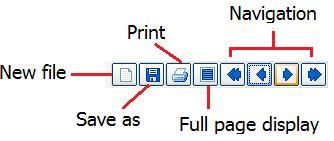
17 Software

18 Setting BATTERY AND FUSE REPLACEMENT
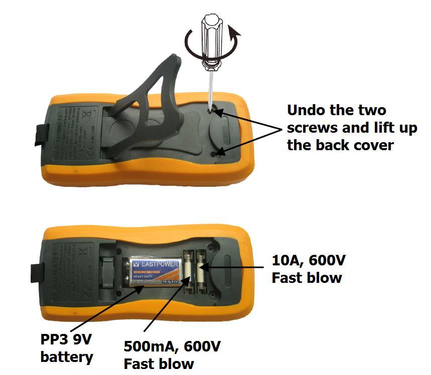
19 1) Battery and fuse replacement should only be carried out after the test leads have been disconnected and the power is off. 2) Loosen screws with a suitable screwdriver and remove case from the bottom. 3) The meter is powered by a single 9V PP3 battery. Snap the battery connector leads to the terminals of a new battery and reinsert the battery into the case top. Tidy the battery leads so that they will not be pinched by the battery cover. 4) The meter is protected by fuses: ma: F0.5A/600V Fast blow. Breaking capacity is 20KA. dimensions are 38 x 10mmØ 10A: F10A/600V Fast blow. Breaking capacity is 20KA. dimensions are 38 x 10mmØ Replace the cover and reinstall the three screws. Never operate the meter unless the case bottom is fully closed. ACCESSORIES Instruction manual Set of test leads (red and black) 9V PP3 battery USB lead Mini CD (software) K type thermocouple Capacitor/Transistor testing adaptor
20 COMPLIES WITH EN :2010 CATIII This product is classed as Electrical or Electronic equipment and should not be disposed with other household or commercial waste at the end of its useful life. The goods must be disposed of according to your local council guidelines. Errors and omissions excepted. Copyright AVSL Group Ltd.
Item ref: UK MTM01 DIGITAL MULTITESTER. User Manual
 Item ref: 600.100UK MTM01 DIGITAL MULTITESTER User Manual Please read this manual thoroughly and ensure all contents are fully understood before using the apparatus. Warning To avoid possible electric
Thank you again for choosing AstroAI, if you have any questions or concerns regarding your product, please contact us at
 ASTROAI USER MANUAL DT132A 4000 Count Auto-Ranging Multimeter Thank you for purchasing the AstroAI DT132A 4000 Count Auto-Ranging Multimeter. It is a 3 ¾ digit, 3999 counts, auto-ranging digital multimeter.
NOTE: Fully read and understand this manual before using this Digital Multimeter.
 ASTROAI USER MANUAL AUTO RANGING DIGITAL CLAMP METER Thank you for purchasing the Auto Ranging Digital Clamp Meter from AstroAI. The AstroAI Auto Ranging Digital Clamp Meter is designed to be safely and
EM420A/420B DIGITAL MULTIMETER OWNERS MANUAL Read this owners manual thoroughly before use
 http://www.all-sun.com EM420A/420B DIGITAL MULTIMETER OWNERS MANUAL V Read this owners manual thoroughly before use WARRANTY This instrument is warranted to be free from defects in material and workmanship
OPERATOR S INSTRUCTION MANUAL
 OPERATOR S INSTRUCTION MANUAL AUTO-RANGE DUAL DISPLAY CONFORMED IEC1010 DIGITAL MULTIMETER CONTENTS PAGE SAFETY INFORMATION..... DESCRIPTION.. OPERATING INSTRUCTION.. SPECIFICATIONS.... ACCESSORIES. BATTERY
KMD-S04 Multímetro de bolsillo
 www.grupotemper.com KMD-S04 Multímetro de bolsillo Table of Contents Title Page Overview ~~~~~~~~~~~~~~~~~~~~~~~~~~~~~~~~~~~~~~~~~~ 3 Unpacking Inspection ~~~~~~~~~~~~~~~~~~~~~~~~~~~~~~~~~ 4 Safety Information
DVM98. True RMS Digital Multimeter. 1 Safety information. 1.1 Preliminary. 1.2 During use
 True RMS Digital Multimeter DVM98 1 Safety information This multimeter has been designed according to IEC - 1010 concerning electronic measuring instruments with an overvoltage category (CAT II) and pollution
AMM-1022 Digital Multimeter USER`S MANUAL
 Digital Multimeter USER`S MANUAL www.tmatlantic.com CONTENTS 1. SAFETY INFORMATION.3 2. DESCRIPTION..6 3. SPECIFICATIONS.8 4. OPERATING INSTRUCTION..11 4.1 Voltage measurement...11 4.2 Current measurement
User Manual Digital Multimeter. model no.: MSR-U1000
 User Manual Digital Multimeter model no.: MSR-U1000 This Operating Manual covers information on safety and cautions. Please read the relevant information carefully and observe all the Warnings and Notes
1. SAFETY 1.1. SAFETY INFORMATION 1.2. SAFETY SYMBOLS
 To all residents of the European Union Important environmental information about this product This symbol on the device or the package indicates that disposal of the device after its lifecycle could harm
UT207A/208A/209A Operating Manual. Table of Contents
 Table of Contents Title Overview Unpacking Inspection Safety Information Rules for Safe Operation International Electrical Symbols The Meter Structure Display Symbols Functional Buttons The Effectiveness
770E DIGITAL MULTIMETER OPERATOR S MANUAL
 770E DIGITAL MULTIMETER OPERATOR S MANUAL TABLE OF CONTENTS 1.Overview... 1 2.Panel Layout...1/2 3. Safety information... 2 4. Specical cautions for operation.... 2 5.General specifications...2/3 6.Testing
1. SAFETY INFORMATION.1 2. DESCRIPTION SPECIFICATIONS.6 4. OPERATING INSTRUCTION Voltage measurement Current measurement 10
 CONTENTS 1. SAFETY INFORMATION.1 2. DESCRIPTION..4 3. SPECIFICATIONS.6 4. OPERATING INSTRUCTION..9 4.1 Voltage measurement...10 4.2 Current measurement 10 4.3 Resistance measurement...12 4.4 Diode test.12
OPERATOR S INSTRUCTION MANUAL M-2625 AUTO RANGING DIGITAL MULTIMETER
 OPERATOR S INSTRUCTION MANUAL M-2625 AUTO RANGING DIGITAL MULTIMETER with Temperature Probe Copyright 2007 Elenco Electronics, Inc. Contents 1. Safety Information 3,4 2. Safety Symbols 5 3. Front Plate
INSTRUCTION MANUAL DIGITAL MULTIMETER
 INSTRUCTION MANUAL DIGITAL MULTIMETER 600 OFF 600 20 2m 2 20m m m 2M 10A k 20k 2k O C NPN PNP hfe E B C E 10A DC 10A MAX UNFUSED MAX 600V COM V ma ma MAX FUSED CAT II 600V Thanks for buying our products,
Model UT10A: OPERATING MANUAL Table of Contents (1)
") Table of Contents (1) Table of Contents Title Page Overview Unpacking Inspection Safety Information Rules For Safe Operation International Electrical Symbols The Meter Structure Functional Buttons Measurement
Table of Contents (1) Table of Contents Title Page Overview Unpacking Inspection Safety Information Rules For Safe Operation International Electrical Symbols The Meter Structure Functional Buttons Measurement
Digital Multi Meter OPERATING INSTRUCTION. Table of Contents
 Table of Contents Digital Multi Meter OPERATING INSTRUCTION 1. Introduction 2. Safety note 3. Explanation of Controls and Indicators 3-1. Product illustration 3-2. Functional push button 3-3. LCD display
OPERATOR S INSTRUCTION MANUAL DIGITAL MULTIMETER
 OPERATOR S INSTRUCTION MANUAL DIGITAL MULTIMETER SAFETY INFORMATION This multimeter has been designed according to IEC 1010 concerning electronic measuring instruments with an overvoltage category (CATⅡ)
Model ST Instruction Manual. True RMS Autoranging Digital Multimeter. reedinstruments. www. com
 Model ST-9933 True RMS Autoranging Digital Multimeter Instruction Manual reedinstruments com Table of Contents Safety... 3 Features... 4 Specifications...4-8 Technical...4-5 Accuracy...5-8 Display Description...
DIGIT & POINTER MULTIMETER
 CONTENTS DIGIT & POINTER MULTIMETER OPERATOR S MANUAL 1. SAFETY INFORMATION 1 1.1 PRELIMINARY 1 1.2 DURING USE 2 1.3 SYMBOLS 3 1.4 MAINTENANCE 3 2. DESCRIPTION 4 2.1 NAMES OF COMPONENTS 4 2.2 FUNCTION
DIGITAL MULTIMETER INSTRUCTION MANUAL
 DIGITAL MULTIMETER INSTRUCTION MANUAL 1 CONTENTS CONTENTS 1. SAFETY INFORMATION 1 1.1 PRELIMINARY 1 1.2 DURING USE 2 1.3 SYMBOLS 3 1.4 MAINTENANCE 4 2. DESCRIPTION 5 2.1 NAMES OF COMPONENTS 5 2.2 SWITCH,
DVM1190 DIGITAL MULTIMETER
 DIGITAL MULTIMETER 1. Introduction Thank you for buying the. This digital multimeter has a large LCD, a data-hold function and a backlight. The device uses a very practical safety mechanism that keeps
MS8250D DUAL DISPLAY DIGITAL MULTIMETER User s Manual
 DUAL DISPLAY DIGITAL MULTIMETER User s Manual MS8250D 1. Safety Information Warning Use caution and follow all safety guidelines to prevent electric shock or damage to the meter. Please ready carefully
OWNER S MANUAL HH0308C. AUTO-RANGING DC/True RMS AC DIGITAL MULTIMETER
 OWNER S MANUAL HH0308C AUTO-RANGING DC/True RMS AC DIGITAL MULTIMETER IMPORTANT! Read and understand this manual before using the tester. Failure to understand and comply with safety rules and operating
3B SCIENTIFIC PHYSICS
 3B SCIENTIFIC PHYSICS Digital Multimeter E 1018832 Instruction sheet 12/16 SD/UD 1 probe 1a Finger guards 2 Measurement socket 10 A for current measurement in 10-A (positive) 3 Measurement socket COM (negative)
Model: &
 600A True RMS Digital Clamp Meter Model: 72-3097 & 72-3099 1 CONTENTS Page Number Details 3 Important Safety Information 4 Product overview 4 Key Functions 5 General Specification 5 Electrical Specification
USER'S MANUAL DMR-6700
 USER'S MANUAL Multimeter True RMS DMR-6700 CIRCUIT-TEST ELECTRONICS www.circuittest.com Introduction This meter measures AC/DC Voltage, AC/DC Current, Resistance, Capacitance, Frequency (electrical & electronic),
AC/DC CLAMP METER USER S MANUAL
 AC/DC CLAMP METER USER S MANUAL CONTENTS PAGE SAFETY INFORMATION SYMBOL EXPLANATION SAFETY PRECAUTIONS 1 1 2 MAINTENANCE 3 GENERAL DESCRIPTION 4 PANEL DESCRIPTION 4 OPERATING INSTRUCTIONS... 7 SPECIFICATIONS
Model : OPERATING MANUAL Table of Contents (1)
") Table of Contents (1) Title Overview Unpacking Inspection Safety Information Rules For Safe Operation International Electrical Symbols The Meter Structure Functional Buttons Measurement Operation A. DC
Table of Contents (1) Title Overview Unpacking Inspection Safety Information Rules For Safe Operation International Electrical Symbols The Meter Structure Functional Buttons Measurement Operation A. DC
DMM8900 SERIES USERS MANUAL
 DMM8900 SERIES USERS MANUAL WARRANTY This instrument is warranted to be free from defects in material and workmanship for a period of one year. Any instrument found defective within one year from the delivery
True RMS Digital Multimeter Model:
 True RMS Digital Multimeter Model: 72-7780 1 SAFETY INFORMATION Please read these instructions carefully before use and retain for future reference. This meter is designed to meet IEC61010-1, 61010-2-032,
User Manual Digital Multimeter
 User Manual Digital Multimeter model no.: MSR-R500 Questions or Concerns? support@etekcity.com visit etekcity.com for more products Safe and Proper Usage Thank you for purchasing the Etekcity MSR-R500
M-1000D DIGITAL MULTIMETER
 OPERATOR S INSTRUCTION MANUAL DIGITAL MULTIMETER M-1000D Elenco Electronics, Inc. 150 Carpenter Avenue Wheeling, IL 60090 (847) 541-3800 Website: www.elenco.com e-mail: elenco@elenco.com Copyright 2008
Digital Multimeter with Backlight
 MODEL: D03126 Digital Multimeter with Backlight 1 CONTENTS Page Number Description 3 Important Safety Information 3 What s Included? 4 Overview 4 Front Panel Description 5 General Specification 5 DC Voltage
AUTO RANGING DIGITAL MULTIMETER
 AUTO RANGING DIGITAL MULTIMETER 12 MONTH WARRANTY LARGE DIGITAL DISPLAY AC/DC VOLTAGE & CURRENT MEASUREMENT CAT II SAFETY RATING CAT III TEST LEAD SAFETY RATING K8315 ED1 May 17 Table of Contents Know
User Manual. All rights reserved. Specifications are subject to change without notice.
 User Manual All rights reserved. Specifications are subject to change without notice. LIMITED WARRANTY AND LIMITATION OF LIABILITY Customers enjoy one-year warranty from the date of purchase. This warranty
Table of Contents Title Page
 Table of Contents Title Page Overview Unpacking Inspection Safety Information Rules For Safe Operation International Electrical Symbols The Meter Structure Rotary Switch Functional Buttons Display Symbols
Digital Clamp Meter Model: &
 Digital Clamp Meter Model: 72-7224 & 72-7226 1 SAFETY INFORMATION Please read these instructions carefully before use and retain for future reference. This meter is designed to meet IEC61010-1, 61010-2-032,
MS8250A/B OPERATION MANUAL MS8250A. Hz% FUNC REL RANGE REL HOLD OFF 10A. Hz% A NCV. Hz% COM. A ma 10A FUSED 600V CAT IV.
 MS8250A/B DIGITAL MULTIMETER OPERATION MANUAL AUTO DC AC REL hfe PCLINK % C F kmωkz nµmfav MS8250A DIGITAL MULTIMETER Auto Power Off RANGE REL HOLD FUNC NCV A ma OFF 10A A ma 10A FUSED 600V CAT IV COM
DIGITAL MULTIMETER OPERATOR'S INSTRUCTION MANUAL HOLD 10A COM LIGHT MS8265 ON/OFF. 200M KHz 2K 20K μ μ μ n.
 MS8265 DIGITAL MULTIMETER OPERATOR'S INSTRUCTION MANUAL HOLD ON/OFF LIGHT 1000V CAT II 600V CAT III MS8265 200K 2M 20M 20K 200M KHz 2K 20 200 2 20 200μ 200 20μ 750 2μ 1000 200n F 20n 10A 2m 200m 10 10
Handheld Digital Multimeter
 Handheld Digital Multimeter GDM-397, GDM-461 USER MANUAL GW INSTEK PART NO. 82DM-46100M01 ISO-9001 CERTIFIED MANUFACTURER This manual contains proprietary information, which is protected by copyright.
IDEAL INDUSTRIES, INC. TECHNICAL MANUAL MODEL: MODEL: Multimeter Service Information
 IDEAL INDUSTRIES, INC. TECHNICAL MANUAL MODEL: 61-340 MODEL: 61-342 Multimeter Service Information The Service Information provides the following information: Precautions and safety information Specifications
Model DIGITAL MULTIMETER
 Model 57070 DIGITAL MULTIMETER INSTRUCTION MANUAL SAFETY INFORMATION To ensure safe operation, and in order to exploit to the full the functionality of the meter, please follow the directions in this section
OPERATING INSTRUCTION
 OPERATING INSTRUCTION AUTOMOTIVE MULTIMETER MODEL QM1444 the finger guards on the probes. Measuring voltage which exceeds the limits of the multimeter may damage the meter and expose the operator to a
Handheld Digital Multimeter
 Handheld Digital Multimeter GDM-360, GDM-397, GDM-398, GDM-461 USER MANUAL GW INSTEK PART NO. 82DM-46100MA1 ISO-9001 CERTIFIED MANUFACTURER This manual contains proprietary information, which is protected
The Meter Structure The Figure 2-1 shows the Meter structure.
 P/N:110401104496X The Meter Structure The Figure 2-1 shows the Meter structure. 1. USB Terminals 2. LCD Display 3. Functional Buttons 4. Rotary Switch 5. Power adaptor Input Terminals 6. 10A Input Terminal
USER MANUAL 600A AC Clamp Meter + NCV Model MA610
 USER MANUAL 600A AC Clamp Meter + NCV Model MA610 Additional User Manual Translations available at www.extech.com Introduction Thank you for selecting the Extech MA610 Clamp Meter. This meter measures
MANUAL DE INSTRUÇÕES DO MULTÍMETRO DIGITAL MODELO MD-6456 Inglês
 MANUAL DE INSTRUÇÕES DO MULTÍMETRO DIGITAL MODELO MD-6456 Inglês Novembro 2016 Leia atentamente as instruções contidas neste manual antes de iniciar o uso do multímetro Table of Contents The Statement...
Model UT201/202: OPERATING MANUAL. Table of Contents
 Table of Contents Title Overview Unpacking Inspection Safety Information Rules For Safe Operation International Electrical Symbols The Meter Structure Rotary Switch Functional Buttons The Effectiveness
DIGITAL MULTIMETER. MODEL CDM-50 Part No OPERATING INSTRUCTIONS
 DIGITAL MULTIMETER MODEL CDM-50 Part No.4500065 OPERATING INSTRUCTIONS 0607 DATA HOLD FUNCTION When this button is pressed, the last reading to be taken will be held on the display, and D-H will appear
User Manual. All rights reserved. Specifications are subject to change without notice.
 User Manual All rights reserved. Specifications are subject to change without notice. LIMITED WARRANTY AND LIMITATION OF LIABILITY Customers enjoy one-year warranty from the date of purchase. This warranty
ProfiScale MULTI Multimeter
 1,5 V 9V 200 mv 600 V 200 ma 1/10 A ProfiScale MULTI Multimeter en Operating instructions BURG-WÄCHTER KG Altenhofer Weg 15 58300 Wetter Germany Introduction Want the reassurance of knowing whether current
Pocket Size Digital Multimeter Models: and
 Pocket Size Digital Multimeter Models: 72-8150 and 72-8155 1 IMPORTANT SAFETY INFORMATION Please read these instructions carefully before use and retain for future reference. Please operate according to
ETHOS 5030 TRUE-RMS DIGITAL MULTIMETER OPERATION MANUAL
 ETHOS 5030 TRUE-RMS DIGITAL MULTIMETER OPERATION MANUAL 1 1. SAFETY INFORMATION SAFETY SYMBOLS Warning! Dangerous Voltage (Risk of electric shock). Caution! Refer to the user s manual before using this
Internetowy sklep elektroniczny. Kontakt. Tel Tel. Kom Fax
 DOKUMENT TEN JEST PRZEZNACZONY DLA KLIENTÓW FIRMY Internetowy sklep elektroniczny WWW.DIOLUT.PL Kontakt Tel. +48 0334866616 Tel. Kom. +48 0888139522 Fax. +48 0334866617 e-mail diolut@diolut.pl Table of
User s Manual. MiniTec TM Series. Model MN26 (Model MN26T includes temperature probe) Mini Autoranging MultiMeter
 Mini Autoranging MultiMeter") User s Manual MiniTec TM Series Model MN26 (Model MN26T includes temperature probe) Mini Autoranging MultiMeter Introduction Congratulations on your purchase of Extech s MN26 Autoranging Multimeter. This
User s Manual MiniTec TM Series Model MN26 (Model MN26T includes temperature probe) Mini Autoranging MultiMeter Introduction Congratulations on your purchase of Extech s MN26 Autoranging Multimeter. This
EX350 Series USER GUIDE. True RMS Digital Multimeters. EX350 True RMS Digital Multimeter EX355 True RMS Digital Multimeter with Temperature
 USER GUIDE True RMS Digital Multimeters EX350 Series EX350 True RMS Digital Multimeter EX355 True RMS Digital Multimeter with Temperature Table of Contents 1. INTRODUCTION 3 2. SAFETY INFORMATION 4 3.
MS2109A AC/DC Clamp Meter. User Manual. Contents
 MS2109A AC/DC Clamp Meter User Manual Contents 1. Safety information 1 1.1 Preparation 1 1.2 Usage 1 1.3 Signs and Labels 2 1.4 Maintenance 2 2. Description 2 2.1 Part name 3 2.2 Switch and button description
Analog Technologies VC99. Multimeter FEATURES
 FEATURES LCD Display Max Display: 6000(3 6/7) Digits Automatic Polarity, Unit Symbol and 61 Section Analog Display Measurement Method: Double Integral A/D Conversion Sampling Rate: Approx.3 times/sec Over-Range
User s Guide. 400A AC/DC Clamp Meter. Model MA Washington Street Melrose, MA Phone Toll Free
 User s Guide 99 Washington Street Melrose, MA 02176 Phone 781-665-1400 Toll Free 1-800-517-8431 Visit us at www.testequipmentdepot.com 400A AC/DC Clamp Meter Model MA220 Introduction Thank you for selecting
User s Guide. MultiView Series Digital MultiMeters Models: MV110 MV120 MV130
 User s Guide MultiView Series Digital MultiMeters Models: MV110 MV120 MV130 WARRANTY EXTECH INSTRUMENTS CORPORATION warrants this instrument to be free of defects in parts and workmanship for one year
DIGITAL DUAL DISPLAY AC/DC CLAMP METER MODEL-860A OPERATION MANUAL
 DIGITAL DUAL DISPLAY AC/DC CLAMP METER MODEL-860A OPERATION MANUAL DIGITAL DUAL DISPLAY AC/DC CLAMP METER MODEL-860A TABLE OF CONTENTS TITLE PAGE Safety Information Safety Symbols... 1 Meter Description...
VC835 DIGTAL MULTIMETER Operation Manual
 VC835 DIGTAL MULTIMETER Operation Manual CONTENTS GENERAL DESCRIPTION Safety Instructions FEATURES OPERATION MAINTENANCE TROUBLE SHOOTING 1. General Description This is a 3 1/2 digital multimeter with
DIGITAL MULTIMETER AUTORANGING
 MODEL: D03124 DIGITAL MULTIMETER AUTORANGING 1 CONTENTS Page Number Details 2 Introduction 2 What s Included 3 Important Safety Information 3 Symbol Guide 4 Overview 5 Buttons 5 Display Indicators 6 General
MODEL: D03128 CLAMP METER
 MODEL: D03128 CLAMP METER 1 CONTENTS Page Number Details 3 Important Safety Information 3 Features 4 Product Overview 5 Switches, Buttons & Input Jacks 5 LCD 6 Specifications 6 Electrical Specifications
Pocket Size Digital Multimeter with USB Model: A & A
 Pocket Size Digital Multimeter with USB Model: 72-7730A & 72-7732A 1 IMPORTANT SAFETY INFORMATION Please read these instructions carefully before use and retain for future reference. This instrument is
UT207/208. Digital Clamp Multimeter P/N:
 UT207/208 Digital Clamp Multimeter P/N: 41451522 Model UT207/208 OPERATING MANUAL Table of Contents Title Overview Unpacking Inspection Safety Information Rules For Safe Operation International Electrical
Handheld Digital Multimeter PRO-50A
 Handheld Digital Multimeter PRO-50A Safety Summary A statement calls attention to an operating procedure, practice, or condition, which, if not followed correctly, could result in injury or death to personnel.
OS-81B TECPEL CO. LTD.
 OS-81B TECPEL CO. LTD. Table of Contents Chapter Title Page 1 Before You Start Overview Unpacking Inspection Safety Information Rules For Safe Operation International Electrical Symbols 2 Using The Testing
DVM645BI BENCH MULTIMETER TAFELMULTIMETER MULTIMETRE DE TABLE BANCO MULTÍMETRO TISCHMULTIMETER. User Manual. Gebruikershandleiding
 BENCH MULTIMETER TAFELMULTIMETER MULTIMETRE DE TABLE BANCO MULTÍMETRO TISCHMULTIMETER User Manual Gebruikershandleiding Manuel d'utilisation Gebrauchsanleitung Introduction BENCH MULTIMETER This manual
User's Guide. 800 Amp AC/DC True RMS Clamp Meter. Model EX Washington Street Melrose, MA Phone Toll Free
 User's Guide 99 Washington Street Melrose, MA 02176 Phone 781-665-1400 Toll Free 1-800-517-8431 Visit us at www.testequipmentdepot.com 800 Amp AC/DC True RMS Clamp Meter Model EX730 Introduction Congratulations
Model UT39A/B/C: OPERATING MANUAL
 TABLE OF CONTENTS TITLE PAGE Overview Unpacking Inspection Safety Information Rules For Safe Operation International Electrical Symbols The Meter Structure Functional Buttons Display Symbols Measurement
INSTRUCTION MANUAL. Model Autoranging DMM ProbeMeter TM. Measures voltage, resistance, frequency, capacitance, temperature, and duty cycle.
 INSTRUCTION MANUAL Model 403380 Autoranging DMM ProbeMeter TM Measures voltage, resistance, frequency, capacitance, temperature, and duty cycle. Back lit LCD with Autorange and full function displays Audible
Digital automotive analyser 13 function with ic
 Digital automotive analyser 13 function with ic Model no: TA201 Thank you for purchasing a Sealey product. Manufactured to a high standard, this product will, if used according to these instructions, and
Model UT20B: OPERATING MANUAL Table of Contents (1)
") Table of Contents (1) Title Overview Unpacking Inspection Safety Information Rules For Safe Operation International Electrical Symbols Rotary Switch Display Symbols Measurement Operation A. AC Voltage
Table of Contents (1) Title Overview Unpacking Inspection Safety Information Rules For Safe Operation International Electrical Symbols Rotary Switch Display Symbols Measurement Operation A. AC Voltage
MM V 10A ENGLISH. INSTRUCTION MANUAL Auto-Ranging DATA HOLD AUDIBLE CONTINUITY MIN / MAX TEMPERATURE DIODE TEST CAPACITANCE
 INSTRUCTION MANUAL Auto-Ranging Digital Multimeter MM400 DATA HOLD AUDIBLE CONTINUITY MIN / MAX TEMPERATURE DIODE TEST CAPACITANCE 600V 10A 40MΩ 2 GENERAL SPECIFICATIONS Klein Tools MM400 is an auto-ranging
DIGITAL MULTIMETER AX-588B
 DIGITAL MULTIMETER AX-588B OPERATION MANUAL 1. Sumary His series product is a stable and battery-driven 3 ½ digital multimeter with high reliability. It adopts LCD screen with character height of 28mm;
USER MANUAL. Model MA A AC Clamp Meter DMM Model MA445 True RMS 400A AC/DC Clamp Meter DMM
 USER MANUAL Model MA440 400A AC Clamp Meter DMM Model MA443 True RMS 400 AC Clamp Meter DMM Model MA445 True RMS 400A AC/DC Clamp Meter DMM Introduction Thank you for selecting the Extech EX44x Series
Mini Clamp Meter Model:
 Mini Clamp Meter Model: 72-2985 1 CONTENTS Page Number Details 2 What s Included 3 Important Safety Information 3 Technical Specification 4 Product Overview 5 LCD Overview 6 Operation - AC/DC Voltage Measurement
RAGU 81D DIGITAL MULTIMETER OPERATION MANUAL
 RAGU 81D DIGITAL MULTIMETER OPERATION MANUAL Contents I. General...- 1 - Ⅱ. Open-package Inspection...- 2 - III. Safety Considerations... - 3 - IV.Instrument Panel & Button Function Description...- 9 -
Compact Autoranging Clamp Meters. Models (400 A AC), (400 A AC/DC)
, (400 A AC/DC)") User Manual Compact Autoranging Clamp Meters with NIST-Traceable Calibration Models 20250-55 (400 A AC), 20250-56 (400 A AC/DC) THE STANDARD IN PRECISION MEASUREMENT 1065DGMAN_20250-55,-56 DS Clamp Meter
User Manual Compact Autoranging Clamp Meters with NIST-Traceable Calibration Models 20250-55 (400 A AC), 20250-56 (400 A AC/DC) THE STANDARD IN PRECISION MEASUREMENT 1065DGMAN_20250-55,-56 DS Clamp Meter
Sales: Technical: Fax:
 DATA SHEET Order code Manufacturer code Description 85-0733 n/a n/a The enclosed information is believed to be correct, Information may change without notice due to product improvement. Users should ensure
Digital Automotive Analyser 14 Function With IC
 Digital Automotive Analyser 14 Function With IC Model no: TA202 Thank you for purchasing a Sealey product. Manufactured to a high standard, this product will, if used according to these instructions, and
MS8250D DUAL DISPLAY DIGITAL MULTIMETER User s Manual
 DUAL DISPLAY DIGITAL MULTIMETER User s Manual MS8250D Introduction MS8250D is a stable, safe, reliable compact digital handheld 6600 count, True RMS, auto-ranging multimeter. This meter can measure AC/DC
MS8223A. CAT.IIi 600 V
 Pen-type Digital Multimeter Manual MS8223A CAT.IIi 600 V CONTENTS 1. Safety Information......1 1.1 Preparing for use...1 1.2 During Use......2 1.3 Safety Symbols...3 1.4 Maintenance...4 2. Description......4
Table of Contents GDM-356. Page
 Table of Contents Title Overview Unpacking Inspection Safety Information Rules For Safe Operation International Electrical Symbols The multimeter Structure Functional Buttons Display Symbols Measurement
400Amp True RMS AC/DC Clamp Meter Model EX613
 User's Guide 400Amp True RMS AC/DC Clamp Meter Model EX613 Introduction Congratulations on your purchase of this Extech EX613 True RMS Clamp Meter. This meter measures AC Current, DC Current, AC/DC Voltage,
Contents 1. General instructions. 1.1 Precautions safety measures Protection mechanisms. 2. Description. 2.1 Instrument Familiarization. 2.
 Contents 1. General instructions. 1.1 Precautions safety measures... 1.2 Protection mechanisms. 2. Description. 2.1 Instrument Familiarization. 2.2 LCD Display 2.3 Keypad. 3. Function description. 3.1
Model UT50D: OPERATING MANUAL. Table of Contents
 Table of Contents Overview Unpacking Inspection Safety Information Rules For Safe Operation International Electrical Symbols The Meter Structure Functional Buttons Display Symbols Measurement Operation
Digital Multimeter, Pen Type
 MODEL: D03127 Digital Multimeter, Pen Type 1 CONTENTS Page Number Description 3 Important Safety Information 3 Electrical Symbols 4 Overview 4 Measurement Operation 5 AC & DC Voltage Measurement 5 AC &
METRAVI. Table of Contents
 Table of Contents A. Your Meter s Feature B. Specifications C. Making Measurements D. Maintenance E. Accessories F. Using Holster G. Using Strap Introduction 540 is brand new Multimeter with 4 1/2 digits,
Digital Multimeter User Manual
 Digital Multimeter User Manual B35(T) D35(T) Note: "T" indicates true RMS (optional) Table of Contents 1.Safety Information... 1 Safety Considerations... 1 Measurement Category... 3 Safety Terms and Symbols...
PEN TYPE DIGITAL MULTIMETER OPERATION MANUAL T8211D
 PEN TYPE DIGITAL MULTIMETER OPERATION MANUAL T8211D T8211D 1 1. SAFETY INFORMATION BE EXTREMELY CAREFUL IN THE USE OF THIS METER. Improper use of this device can result in electric shock or destroy of
MM700. True RMS ENGLISH. INSTRUCTION MANUAL Auto-Ranging. Measurement Technology
 INSTRUCTION MANUAL Auto-Ranging Digital Multimeter er True RMS Measurement Technology MM700 DATA & RANGE HOLD LOW IMPEDANCE AUDIBLE CONTINUITY MIN / MAX / RELATIVE TEMPERATURE DIODE TEST CAPACITANCE &
AC/DC DIGITAL CLAMP METER OPERATION MANUAL
 AC/DC DIGITAL CLAMP METER OPERATION MANUAL HYS005661 A0 ACCESSORIES 6. ACCESSORIES 1) Test Leads: Electric Ratings 1000V 10A 1 pair (set) 2) Operating Manual 1 copy 3) 1.5V AAA Battery 3 piece - - 55 -
DIGITAL MULTIMETER OPERATING INSTRUCTIONS MODEL CDM-35. Part No
 DIGITAL MULTIMETER MODEL CDM-35 Part No.4500055 OPERATING INSTRUCTIONS 0304 The Meter may be hung on a wall, or supported as shown, depending upon which support is used. The probes may be located as shown,
INSTRUCTION MANUAL MODEL 21 MULTI-TESTER
 INSTRUCTION MANUAL MODEL 21 MULTI-TESTER 5 IN 1 SOUND LEVEL LIGHT HUMIDITY TEMPERATURE MULTIMETER .TABLET OF CONTENTS TITLE 1. INTRODUCTION 2 2. INFORMATION FOR SAFETY 2 3. FEATURES 4 4. SPECIFICATIONS
MM700. INSTRUCTION MANUAL Auto-Ranging Digital Multimeter True RMS
 INSTRUCTION MANUAL Auto-Ranging Digital Multimeter True RMS Measurement Technology MM700 DATA & RANGE HOLD LOW IMPEDANCE AUDIBLE CONTINUITY MIN / MAX / RELATIVE TEMPERATURE DIODE TEST CAPACITANCE & FREQUENCY
Model UT61A/61B/61C/61D/61E: OPERATING MANUAL. Table of Contents
 Table of Contents Title Overview Unpacking Inspection Safety Information Rules For Safe Operation International Electrical Symbols The Meter Structure Rotary Switch Functional Buttons Display Symbols Measurement
Accuracy : ± (0.8% rdg + 1dgt) on all ranges except Ranges : 200mV, 2V, 20V, 200V, 1000V
 on all ranges except Ranges : 200mV, 2V, 20V, 200V, 1000V") . SPECIFICATIONS Digital Multimeter Model : 0 Instruction Manual. General Specifications Display : ½ digit liquid crystal display (LCD) with a maximum reading of 999. Polarity : Automatic, (-)negative
. SPECIFICATIONS Digital Multimeter Model : 0 Instruction Manual. General Specifications Display : ½ digit liquid crystal display (LCD) with a maximum reading of 999. Polarity : Automatic, (-)negative