Differential Mode Group Delay (DMGD) in Few Mode Fibers (FMF)
|
|
|
- Susan Clark
- 5 years ago
- Views:
Transcription
1 Differential Mode Group Delay (DMGD) in Few Mode Fibers (FMF) Microwave Interferometric Technique for Characterizing Few Mode Fibers Abstract We propose and experimentally demonstrate a simple and accurate technique for measuring differential mode group delay (DMGD) in few mode fibers (FMF). A frequency-swept microwave signal is modulated on a filtered optical incoherent source. The microwave signals carried on different fiber modes experience different time delays and interfere with each other in the photodetector. Optical interference between propagating fiber modes is avoided by the use of an incoherent optical source. A mathematical model is established to analyze the interference pattern and extract the DMGD values. A 456-m two-mode fiber and a 981-m FMF, which supports four LP modes, are measured. The measurement covers the whole C-band and the results coincide well with those obtained by the time-of-flight method and the numerical simulations. A precision of ±0.002 ps/m is achieved. [1] Introduction: Few mode fibers (FMF) have been recently employed in mode division multiplexing (MDM) which is considered to be a promising solution for scaling the data-carrying capacity of networks. Differential mode group delay (DMGD) is an important parameter of FMFs and should be carefully chosen in fiber design. Project Layout Since the core has a higher index of refraction than the cladding, light will be confined to the core if the angular condition for Total Internal Reflectance is met. The fiber geometry and composition determine the discrete set of electromagnetic fields, or fiber modes, which can propagate in the fiber. Figure 1 (a) illustrates a step-index fiber having a uniform core of radius (a) with one index of refraction (n core), and a uniform cladding with a smaller index of refraction (n cladding). The OptiFiber profile layout is shown in Fig. 1 (b). Figure 1: (a) A cross section plane view through a step-index fiber and (b) OptiFiber Profile layout.

. Fiber parameter (V) V < 2.405 2.405<V<3.832 3.832<V<5.136 5.136<V<5.520 5.520<V<6.")
2 FMF Design The fiber parameter (V) that plays an important role in determining the cut-off condition of the propagating modes is given by: V = 2πa NA, λ where λ is the operating wavelength and NA is the numerical aperture. The numerical aperture is a measure of the acceptance angle of the fiber. It is very important because it determines how strongly a fiber guides light, and so how resistant it is to bend-induced losses. It is given by: NA = 2 2 n core n cladding. The following table summarizes the propagating modes according to the fiber parameter (V). Fiber parameter (V) V < <V< <V< <V< <V<6.380 LP01 LP01, LP11 Table 1: The existing propagating modes for a given range of V parameter. 1. FMF supports 2-modes Modes LP01, LP11, LP02, LP21 LP01, LP11, LP02, LP21, LP31 LP01, LP11, LP02, LP21, LP31, LP12 Numerical simulations were performed assuming a step index profile with a NA of 0.17 and core diameter of 15 μm [1]. Design Fiber Profile: Core refractive index n core= ; 0 < r < 7.5 µm Cladding refractive index n cladding= ; 7.5 µm < r < 62.5 µm


3 Calculating Fiber Modes: From the parameters of this fiber the V parameter is, V=3.78, which determines that the fiber should support 2 modes. The numerical calculations show that indeed the fiber supports two guided modes: LP 01, LP FMF supports 4-modes Numerical simulations were performed assuming a step index profile with a NA of and core diameter of 16.4 μm [1]. Design Fiber Profile: Core refractive index n core= ; 0 < r < 8.2 µm Cladding refractive index n cladding= ; 8.2µm < r < 62.5 µm


4 Calculating Fiber Modes: From the parameters of this fiber the V parameter is, V=5.16, which determines that the fiber should support 5 modes. The numerical calculations show that indeed the fiber supports five guided modes: LP 01, LP 11, LP 02, LP 21 and LP 31. LP 31 is not further analyzed in the simulations because it is very close to cut-off conditions. Results In order to calculate Differential Mode Group Delay (DMGD) at different wavelengths: 1- The propagation mode is selected. (Either for the fundamental mode or the higher modes). 2- The group delay at different wavelengths is extracted.

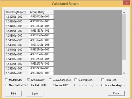

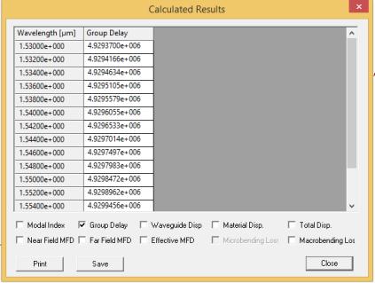
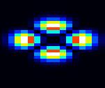
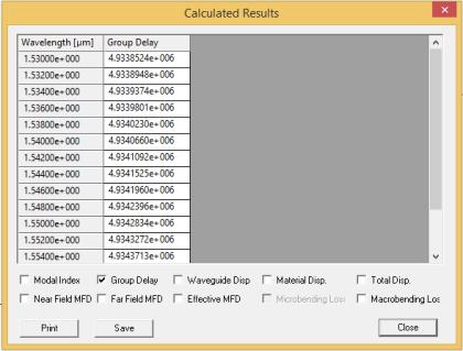
5 FMF supports 4-modes Fundamental Mode LP 01 Mode LP 02 Mode LP 11 Mode LP 21
 FMF supports 4-modes FMF supports 2-modes LP 11 LP 01 (ps/m) LP 02 LP 01 (ps/m) LP 21 LP 01 (ps/m) LP 11 LP 01 (ps/m) 1.530 4.424 8.068 8.886 1.926 1.532 4.429 8.046 8.886 1.922 1.")

6 FMF supports 2-modes Fundamental Mode LP 01 Mode LP DMGD are then calculated between each higher mode and the fundamental mode. λ (µm) FMF supports 4-modes FMF supports 2-modes LP 11 LP 01 (ps/m) LP 02 LP 01 (ps/m) LP 21 LP 01 (ps/m) LP 11 LP 01 (ps/m)
7 4- DMGD is finally plotted at different wavelengths. Figure 2: (a) Simulated DMGD for four mode fiber and (b) Experimental results [1]. Figure 3: (a) Simulated DMGD for two mode fiber and (b) Experimental results [1]. Figures 2 and 3 demonstrate that the experimental results [1] agree with the simulated DMGD for the two and four mode fibers. References [1] Lixian Wang, Cang Jin, Younès Messaddeq, and Sophie LaRochelle, Microwave Interferometric Technique for Characterizing Few Mode Fibers, IEEE PHOTONICS TECHNOLOGY LETTERS, 26 (17), , 2014.
Characterization of Few Mode Fibers by OLCI Technique
 Characterization of Few Mode Fibers by OLCI Technique R. Gabet, Elodie Le Cren, C. Jin, Michel Gadonna, B. Ung, Y. Jaouen, Monique Thual, Sophie La Rochelle To cite this version: R. Gabet, Elodie Le Cren,
Fiber Optic Communication Systems. Unit-05: Types of Fibers. https://sites.google.com/a/faculty.muet.edu.pk/abdullatif
 Unit-05: Types of Fibers https://sites.google.com/a/faculty.muet.edu.pk/abdullatif Department of Telecommunication, MUET UET Jamshoro 1 Optical Fiber Department of Telecommunication, MUET UET Jamshoro
Test procedures Page: 1 of 5
 Test procedures Page: 1 of 5 1 Scope This part of document establishes uniform requirements for measuring the numerical aperture of optical fibre, thereby assisting in the inspection of fibres and cables
White Paper: The Ins and Outs of Testing Bend Insensitive Multimode Fiber (BIMMF): The Need for Encircled Flux
: The Need for Encircled Flux") White Paper: The Ins and Outs of Testing Bend Insensitive Multimode Fiber (BIMMF): The Need for Encircled Flux White Paper: The Ins and Outs of Testing Bend Insensitive Multimode Fiber (BIMMF): The Need
White Paper: The Ins and Outs of Testing Bend Insensitive Multimode Fiber (BIMMF): The Need for Encircled Flux White Paper: The Ins and Outs of Testing Bend Insensitive Multimode Fiber (BIMMF): The Need
Fiber Optic Communications
 Fiber Optic Communications ( Chapter 2: Optics Review ) presented by Prof. Kwang-Chun Ho 1 Section 2.4: Numerical Aperture Consider an optical receiver: where the diameter of photodetector surface area
Design of a double clad optical fiber with particular consideration of leakage losses
 Vol. (4), pp. 7-62 October, 23 DOI.897/JEEER23.467 ISSN 993 822 23 Academic Journals http://www.academicjournals.org/jeeer Journal of Electrical and Electronics Engineering Research Full Length Research
Physics 431 Final Exam Examples (3:00-5:00 pm 12/16/2009) TIME ALLOTTED: 120 MINUTES Name: Signature:
 TIME ALLOTTED: 120 MINUTES Name: Signature:") Physics 431 Final Exam Examples (3:00-5:00 pm 12/16/2009) TIME ALLOTTED: 120 MINUTES Name: PID: Signature: CLOSED BOOK. TWO 8 1/2 X 11 SHEET OF NOTES (double sided is allowed), AND SCIENTIFIC POCKET CALCULATOR
Physics 431 Final Exam Examples (3:00-5:00 pm 12/16/2009) TIME ALLOTTED: 120 MINUTES Name: PID: Signature: CLOSED BOOK. TWO 8 1/2 X 11 SHEET OF NOTES (double sided is allowed), AND SCIENTIFIC POCKET CALCULATOR
Fiber Optic Communications Communication Systems
 INTRODUCTION TO FIBER-OPTIC COMMUNICATIONS A fiber-optic system is similar to the copper wire system in many respects. The difference is that fiber-optics use light pulses to transmit information down
FIBER OPTICS. Dr D. Arun Kumar Assistant Professor Department of Physical Sciences Bannari Amman Institute of Technology Sathyamangalam
 FIBER OPTICS Dr D. Arun Kumar Assistant Professor Department of Physical Sciences Bannari Amman Institute of Technology Sathyamangalam General Objective To understand the propagation of light through optical
Fiber Optic Communication Systems. Unit-04: Theory of Light. https://sites.google.com/a/faculty.muet.edu.pk/abdullatif
 Unit-04: Theory of Light https://sites.google.com/a/faculty.muet.edu.pk/abdullatif Department of Telecommunication, MUET UET Jamshoro 1 Limitations of Ray theory Ray theory describes only the direction
Examination Optoelectronic Communication Technology. April 11, Name: Student ID number: OCT1 1: OCT 2: OCT 3: OCT 4: Total: Grade:
 Examination Optoelectronic Communication Technology April, 26 Name: Student ID number: OCT : OCT 2: OCT 3: OCT 4: Total: Grade: Declaration of Consent I hereby agree to have my exam results published on
Design and Simulation of Optical Power Splitter By using SOI Material
 J. Pure Appl. & Ind. Phys. Vol.3 (3), 193-197 (2013) Design and Simulation of Optical Power Splitter By using SOI Material NAGARAJU PENDAM * and C P VARDHANI 1 * Research Scholar, Department of Physics,
Ultra-Compact Photonic Crystal Based Water Temperature Sensor
 PHOTONIC SENSORS / Vol. 6, No. 3, 2016: 274 278 Ultra-Compact Photonic Crystal Based Water Temperature Sensor Mahmoud NIKOUFARD *, Masoud KAZEMI ALAMOUTI, and Alireza ADEL Department of Electronics, Faculty
EE119 Introduction to Optical Engineering Spring 2003 Final Exam. Name:
 EE119 Introduction to Optical Engineering Spring 2003 Final Exam Name: SID: CLOSED BOOK. THREE 8 1/2 X 11 SHEETS OF NOTES, AND SCIENTIFIC POCKET CALCULATOR PERMITTED. TIME ALLOTTED: 180 MINUTES Fundamental
Multimode Optical Fiber
 Multimode Optical Fiber 1 OBJECTIVE Determine the optical modes that exist for multimode step index fibers and investigate their performance on optical systems. 2 PRE-LAB The backbone of optical systems
Optical Fiber Technology. Photonic Network By Dr. M H Zaidi
 Optical Fiber Technology Numerical Aperture (NA) What is numerical aperture (NA)? Numerical aperture is the measure of the light gathering ability of optical fiber The higher the NA, the larger the core
Absorption: in an OF, the loss of Optical power, resulting from conversion of that power into heat.
 Absorption: in an OF, the loss of Optical power, resulting from conversion of that power into heat. Scattering: The changes in direction of light confined within an OF, occurring due to imperfection in
You won t be able to measure the incident power precisely. The readout of the power would be lower than the real incident power.
 1. a) Given the transfer function of a detector (below), label and describe these terms: i. dynamic range ii. linear dynamic range iii. sensitivity iv. responsivity b) Imagine you are using an optical
OPTICAL FIBER-BASED SENSING OF STRAIN AND TEMPERATURE
 OPTICAL FIBER-BASED SENSING OF STRAIN AND TEMPERATURE AT HIGH TEMPERATURE K. A. Murphy, C. Koob, M. Miller, S. Feth, and R. O. Claus Fiber & Electro-Optics Research Center Electrical Engineering Department
arxiv:physics/ v1 [physics.optics] 28 Sep 2005
![arxiv:physics/ v1 [physics.optics] 28 Sep 2005](/thumbs/91/105523130.jpg "arxiv:physics/ v1 [physics.optics] 28 Sep 2005") Near-field enhancement and imaging in double cylindrical polariton-resonant structures: Enlarging perfect lens Pekka Alitalo, Stanislav Maslovski, and Sergei Tretyakov arxiv:physics/0509232v1 [physics.optics]
Near-field enhancement and imaging in double cylindrical polariton-resonant structures: Enlarging perfect lens Pekka Alitalo, Stanislav Maslovski, and Sergei Tretyakov arxiv:physics/0509232v1 [physics.optics]
Effective Cutoff Wavelength Measurement of Bend-insensitive Fiber by Longitudinal Misalignment Loss Method. Won-Taek Han
 Advanced Materials Research Vols. 123-125 (2010) pp 419-422 Online available since 2010/Aug/11 at www.scientific.net (2010) Trans Tech Publications, Switzerland doi:10.4028/www.scientific.net/amr.123-125.419
UNIT-II : SIGNAL DEGRADATION IN OPTICAL FIBERS
 UNIT-II : SIGNAL DEGRADATION IN OPTICAL FIBERS The Signal Transmitting through the fiber is degraded by two mechanisms. i) Attenuation ii) Dispersion Both are important to determine the transmission characteristics
is a method of transmitting information from one place to another by sending light through an optical fiber. The light forms an electromagnetic
 is a method of transmitting information from one place to another by sending light through an optical fiber. The light forms an electromagnetic carrier wave that is modulated to carry information. The
Lectureo5 FIBRE OPTICS. Unit-03
 Lectureo5 FIBRE OPTICS Unit-03 INTRODUCTION FUNDAMENTAL IDEAS ABOUT OPTICAL FIBRE Multimode Fibres Multimode Step Index Fibres Multimode Graded Index Fibres INTRODUCTION In communication systems, there
SUPPLEMENTARY INFORMATION
 Silver permittivity used in the simulations Silver permittivity values are obtained from Johnson & Christy s experimental data 31 and are fitted with a spline interpolation in order to estimate the permittivity
Fiber Optics Dr. Vipul Rastogi Department of Physics Indian Institute of Technology, Roorkee. Lecture - 04 Salient features of optical fiber II
 Fiber Optics Dr. Vipul Rastogi Department of Physics Indian Institute of Technology, Roorkee Lecture - 04 Salient features of optical fiber II In the last lecture we had understood the propagation characteristics
SSRG International Journal of Electronics and Communication Engineering (SSRG-IJECE) Volume 2 Issue 6 June 2015
 Volume 2 Issue 6 June 2015") SSRG International Journal of Electronics and Communication Engineering (SSRG-IJECE) Volume Issue 6 June 15 Designing of a Long Period Fiber Grating (LPFG) using Optigrating Simulation Software Mr. Puneet
SSRG International Journal of Electronics and Communication Engineering (SSRG-IJECE) Volume Issue 6 June 15 Designing of a Long Period Fiber Grating (LPFG) using Optigrating Simulation Software Mr. Puneet
Analysis of Self Phase Modulation Fiber nonlinearity in Optical Transmission System with Dispersion
 36 Analysis of Self Phase Modulation Fiber nonlinearity in Optical Transmission System with Dispersion Supreet Singh 1, Kulwinder Singh 2 1 Department of Electronics and Communication Engineering, Punjabi
Silicon Photonic Device Based on Bragg Grating Waveguide
 Silicon Photonic Device Based on Bragg Grating Waveguide Hwee-Gee Teo, 1 Ming-Bin Yu, 1 Guo-Qiang Lo, 1 Kazuhiro Goi, 2 Ken Sakuma, 2 Kensuke Ogawa, 2 Ning Guan, 2 and Yong-Tsong Tan 2 Silicon photonics
Guided Propagation Along the Optical Fiber. Xavier Fernando Ryerson Comm. Lab
 Guided Propagation Along the Optical Fiber Xavier Fernando Ryerson Comm. Lab The Nature of Light Quantum Theory Light consists of small particles (photons) Wave Theory Light travels as a transverse electromagnetic
Applying of refractive beam shapers of circular symmetry to generate non-circular shapes of homogenized laser beams
 - 1 - Applying of refractive beam shapers of circular symmetry to generate non-circular shapes of homogenized laser beams Alexander Laskin a, Vadim Laskin b a MolTech GmbH, Rudower Chaussee 29-31, 12489
Ratiometric Wavelength Monitor Based on Singlemode-Multimode-Singlemode Fiber Structure
 Dublin Institute of Technology ARROW@DIT Articles School of Electrical and Electronic Engineering 8-1-1 Ratiometric Wavelength Monitor Based on Singlemode-Multimode-Singlemode Fiber Structure Agus Hatta
SIGNAL DEGRADATION IN OPTICAL FIBERS
 Volume Issue January 04, ISSN 348 8050 SIGNAL DEGRADATION IN OPTICAL FIBERS Gyan Prakash Pal, Manishankar Gupta,,, Assistant Professor, Electronics & Communication Engineering Department, Shanti Institute
CHAPTER 7. Waveguide writing in optimal conditions. 7.1 Introduction
 CHAPTER 7 7.1 Introduction In this chapter, we want to emphasize the technological interest of controlled laser-processing in dielectric materials. Since the first report of femtosecond laser induced refractive
The Effect of Radiation Coupling in Higher Order Fiber Bragg Gratings
 PIERS ONLINE, VOL. 3, NO. 4, 27 462 The Effect of Radiation Coupling in Higher Order Fiber Bragg Gratings Li Yang 1, Wei-Ping Huang 2, and Xi-Jia Gu 3 1 Department EEIS, University of Science and Technology
Directional coupler (2 Students)
") Directional coupler (2 Students) The goal of this project is to make a 2 by 2 optical directional coupler with a defined power ratio for the two output branches. The directional coupler should be optimized
Directional coupler (2 Students) The goal of this project is to make a 2 by 2 optical directional coupler with a defined power ratio for the two output branches. The directional coupler should be optimized
Title. CitationIEEE photonics journal, 8(3): Issue Date Doc URL. Rights. Type. File Information.
: Issue Date Doc URL. Rights. Type. File Information.") Title Theoretical Investigation of Six-Mode Multi/Demultip Author(s)Nishimoto, Shoko; Fujisawa, Takeshi; Sasaki, Yusuke; CitationIEEE photonics journal, 8(3): 7802908 Issue Date 2016-06 Doc URL http://hdl.handle.net/2115/62373
Title Theoretical Investigation of Six-Mode Multi/Demultip Author(s)Nishimoto, Shoko; Fujisawa, Takeshi; Sasaki, Yusuke; CitationIEEE photonics journal, 8(3): 7802908 Issue Date 2016-06 Doc URL http://hdl.handle.net/2115/62373
Chapter 3. Introduction to Zemax. 3.1 Introduction. 3.2 Zemax
 Chapter 3 Introduction to Zemax 3.1 Introduction Ray tracing is practical only for paraxial analysis. Computing aberrations and diffraction effects are time consuming. Optical Designers need some popular
Optical RI sensor based on an in-fiber Bragg grating. Fabry-Perot cavity embedded with a micro-channel
 Optical RI sensor based on an in-fiber Bragg grating Fabry-Perot cavity embedded with a micro-channel Zhijun Yan *, Pouneh Saffari, Kaiming Zhou, Adedotun Adebay, Lin Zhang Photonic Research Group, Aston
HYBRID ARRAY ANTENNA FOR BROADBAND MILLIMETER-WAVE APPLICATIONS
 Progress In Electromagnetics Research, PIER 83, 173 183, 2008 HYBRID ARRAY ANTENNA FOR BROADBAND MILLIMETER-WAVE APPLICATIONS S. Costanzo, I. Venneri, G. Di Massa, and G. Amendola Dipartimento di Elettronica,
Guided Propagation Along the Optical Fiber. Xavier Fernando Ryerson University
 Guided Propagation Along the Optical Fiber Xavier Fernando Ryerson University The Nature of Light Quantum Theory Light consists of small particles (photons) Wave Theory Light travels as a transverse electromagnetic
Pixel-remapping waveguide addition to an internally sensed optical phased array
 Pixel-remapping waveguide addition to an internally sensed optical phased array Paul G. Sibley 1,, Robert L. Ward 1,, Lyle E. Roberts 1,, Samuel P. Francis 1,, Simon Gross 3, Daniel A. Shaddock 1, 1 Space
FRAUNHOFER AND FRESNEL DIFFRACTION IN ONE DIMENSION
 FRAUNHOFER AND FRESNEL DIFFRACTION IN ONE DIMENSION Revised November 15, 2017 INTRODUCTION The simplest and most commonly described examples of diffraction and interference from two-dimensional apertures
Fabrication of Probes for High Resolution Optical Microscopy
 Fabrication of Probes for High Resolution Optical Microscopy Physics 564 Applied Optics Professor Andrès La Rosa David Logan May 27, 2010 Abstract Near Field Scanning Optical Microscopy (NSOM) is a technique
EXPRIMENT 3 COUPLING FIBERS TO SEMICONDUCTOR SOURCES
 EXPRIMENT 3 COUPLING FIBERS TO SEMICONDUCTOR SOURCES OBJECTIVES In this lab, firstly you will learn to couple semiconductor sources, i.e., lightemitting diodes (LED's), to optical fibers. The coupling
FIBER OPTICS. Prof. R.K. Shevgaonkar. Department of Electrical Engineering. Indian Institute of Technology, Bombay. Lecture: 4
 FIBER OPTICS Prof. R.K. Shevgaonkar Department of Electrical Engineering Indian Institute of Technology, Bombay Lecture: 4 Modal Propagation of Light in an Optical Fiber Fiber Optics, Prof. R.K. Shevgaonkar,
Novel multi-core fibers for mode division multiplexing: proposal and design principle
 Novel multi-core fibers for mode division multiplexing: proposal and design principle Yasuo Kokubun 1a) and Masanori Koshiba 2 1 Graduate School of Engineering, Yokohama National University, 79 5 Tokiwadai,
InP-based Waveguide Photodetector with Integrated Photon Multiplication
 InP-based Waveguide Photodetector with Integrated Photon Multiplication D.Pasquariello,J.Piprek,D.Lasaosa,andJ.E.Bowers Electrical and Computer Engineering Department University of California, Santa Barbara,
Electromagnetic Radiation
 Electromagnetic Radiation EMR Light: Interference and Optics I. Light as a Wave - wave basics review - electromagnetic radiation II. Diffraction and Interference - diffraction, Huygen s principle - superposition,
1. Explain in detail with necessary circuit diagram and advantages of trans impedance amplifier. [M/J-16] 10MARKS Transimpedance Preamplifier:
![1. Explain in detail with necessary circuit diagram and advantages of trans impedance amplifier. [M/J-16] 10MARKS Transimpedance Preamplifier:](/thumbs/89/99807561.jpg "1. Explain in detail with necessary circuit diagram and advantages of trans impedance amplifier. [M/J-16] 10MARKS Transimpedance Preamplifier:") 1. Explain in detail with necessary circuit diagram and advantages of trans impedance amplifier. [M/J-16] 10MARKS Transimpedance Preamplifier: Figure 4.11 Equivalent Circuit of the Transimpedance Receiver
1. Explain in detail with necessary circuit diagram and advantages of trans impedance amplifier. [M/J-16] 10MARKS Transimpedance Preamplifier: Figure 4.11 Equivalent Circuit of the Transimpedance Receiver
The Formation of an Aerial Image, part 2
 T h e L i t h o g r a p h y T u t o r (April 1993) The Formation of an Aerial Image, part 2 Chris A. Mack, FINLE Technologies, Austin, Texas In the last issue, we began to described how a projection system
Splice losses in holey optical fibers
 Splice losses in holey optical fibers J.T. Lizier and G.E. Town School of Electrical and Information Engineering (J03), University of Sydney, NSW 2006, Australia. Tel: +612-9351-2110, Fax: +612-9351-3847,
A thin foil optical strain gage based on silicon-on-insulator microresonators
 A thin foil optical strain gage based on silicon-on-insulator microresonators D. Taillaert* a, W. Van Paepegem b, J. Vlekken c, R. Baets a a Photonics research group, Ghent University - INTEC, St-Pietersnieuwstraat
How Bend Insensitive Multimode Fiber is Affecting Installation and Testing of Enterprise and Data Center Cabling
 How Bend Insensitive Multimode Fiber is Affecting Installation and Testing of Enterprise and Data Center Cabling David Mazzarese, Technical Manager, Fiber Systems and Standards Engineering, OFS Learning
Monitoring damage growth in composite materials by FBG sensors
 5th International Symposium on NDT in Aerospace, 13-15th November 2013, Singapore Monitoring damage growth in composite materials by FBG sensors Alfredo GÜEMES, Antonio FERNANDEZ-LOPEZ, Borja HERNANDEZ-CRESPO
Chapter 18: Fiber Optic and Laser Technology
 Chapter 18: Fiber Optic and Laser Technology Chapter 18 Objectives At the conclusion of this chapter, the reader will be able to: Describe the construction of fiber optic cable. Describe the propagation
UNIT Write notes on broadening of pulse in the fiber dispersion?
 UNIT 3 1. Write notes on broadening of pulse in the fiber dispersion? Ans: The dispersion of the transmitted optical signal causes distortion for both digital and analog transmission along optical fibers.
Analytical analysis of modulated signal in apertureless scanning near-field optical microscopy C. H. Chuang and Y. L. Lo *
 Research Express@NCKU Volume 5 Issue 10 - October 3, 2008 [ http://research.ncku.edu.tw/re/articles/e/20081003/2.html ] Analytical analysis of modulated signal in apertureless scanning near-field optical
Transmitting Light: Fiber-optic and Free-space Communications Holography
 1 Lecture 9 Transmitting Light: Fiber-optic and Free-space Communications Holography 2 Wireless Phone Calls http://havilandtelconews.com/2011/10/the-reality-behind-wireless-networks/ 3 Undersea Cable and
1 COPYRIGHT 2011 ALCATEL-LUCENT. ALL RIGHTS RESERVED.
 1 ECOC 2011 WORKSHOP Space-Division Multiplexed Transmission in Strongly Coupled Few-Mode and Multi-Core Fibers Roland Ryf September 18 th 2011 CONTENTS 1. THE CAPACITY CRUNCH 2. SPACE DIVISION MULTIPLEXING
1. Evolution Of Fiber Optic Systems
 OPTICAL FIBER COMMUNICATION UNIT-I : OPTICAL FIBERS STRUCTURE: 1. Evolution Of Fiber Optic Systems The operating range of optical fiber system term and the characteristics of the four key components of
Analysis of Dispersion of Single Mode Optical Fiber
 Daffodil International University Institutional Repository Proceedings of NCCIS November 007 007-11-4 Analysis of Dispersion of Single Mode Optical Fiber Hossen, Monir Daffodil International University
MATHEMATICAL MODELING OF RING RESONATOR FILTERS FOR PHOTONIC APPLICATIONS
 MATHEMATICAL MODELING OF RING RESONATOR FILTERS FOR PHOTONIC APPLICATIONS Jyoti Kedia 1 (Assistant professor), Dr. Neena Gupta 2 (Associate Professor, Member IEEE) 1,2 PEC University of Technology, Sector
SINGLE-FEEDING CIRCULARLY POLARIZED TM 21 - MODE ANNULAR-RING MICROSTRIP ANTENNA FOR MOBILE SATELLITE COMMUNICATION
 Progress In Electromagnetics Research Letters, Vol. 20, 147 156, 2011 SINGLE-FEEDING CIRCULARLY POLARIZED TM 21 - MODE ANNULAR-RING MICROSTRIP ANTENNA FOR MOBILE SATELLITE COMMUNICATION X. Chen, G. Fu,
Photonics and Optical Communication
 Photonics and Optical Communication (Course Number 300352) Spring 2007 Dr. Dietmar Knipp Assistant Professor of Electrical Engineering http://www.faculty.iu-bremen.de/dknipp/ 1 Photonics and Optical Communication
A broadband achromatic metalens for focusing and imaging in the visible
 SUPPLEMENTARY INFORMATION Articles https://doi.org/10.1038/s41565-017-0034-6 In the format provided by the authors and unedited. A broadband achromatic metalens for focusing and imaging in the visible
Chapter Ray and Wave Optics
 109 Chapter Ray and Wave Optics 1. An astronomical telescope has a large aperture to [2002] reduce spherical aberration have high resolution increase span of observation have low dispersion. 2. If two
arxiv:physics/ v1 [physics.optics] 25 Aug 2003
![arxiv:physics/ v1 [physics.optics] 25 Aug 2003](/thumbs/84/90868967.jpg "arxiv:physics/ v1 [physics.optics] 25 Aug 2003") arxiv:physics/0308087v1 [physics.optics] 25 Aug 2003 Multi-mode photonic crystal fibers for VCSEL based data transmission N. A. Mortensen, 1 M. Stach, 2 J. Broeng, 1 A. Petersson, 1 H. R. Simonsen, 1 and
arxiv:physics/0308087v1 [physics.optics] 25 Aug 2003 Multi-mode photonic crystal fibers for VCSEL based data transmission N. A. Mortensen, 1 M. Stach, 2 J. Broeng, 1 A. Petersson, 1 H. R. Simonsen, 1 and
CHAPTER 2 POLARIZATION SPLITTER- ROTATOR BASED ON A DOUBLE- ETCHED DIRECTIONAL COUPLER
 CHAPTER 2 POLARIZATION SPLITTER- ROTATOR BASED ON A DOUBLE- ETCHED DIRECTIONAL COUPLER As we discussed in chapter 1, silicon photonics has received much attention in the last decade. The main reason is
CHIRPED FIBER BRAGG GRATING (CFBG) BY ETCHING TECHNIQUE FOR SIMULTANEOUS TEMPERATURE AND REFRACTIVE INDEX SENSING
 BY ETCHING TECHNIQUE FOR SIMULTANEOUS TEMPERATURE AND REFRACTIVE INDEX SENSING") CHIRPED FIBER BRAGG GRATING (CFBG) BY ETCHING TECHNIQUE FOR SIMULTANEOUS TEMPERATURE AND REFRACTIVE INDEX SENSING Siti Aisyah bt. Ibrahim and Chong Wu Yi Photonics Research Center Department of Physics,
CHIRPED FIBER BRAGG GRATING (CFBG) BY ETCHING TECHNIQUE FOR SIMULTANEOUS TEMPERATURE AND REFRACTIVE INDEX SENSING Siti Aisyah bt. Ibrahim and Chong Wu Yi Photonics Research Center Department of Physics,
RF photonic delay lines using space-division multiplexing
 RF photonic delay lines using space-division multiplexing S. Garcia and I. Gasulla ITEAM Research Institute, Universitat Politècnica de València, 46022 Valencia, Spain ABSTRACT We review our last work
Fiberoptic and Waveguide Sensors
 Fiberoptic and Waveguide Sensors Wei-Chih Wang Department of Mecahnical Engineering University of Washington Optical sensors Advantages: -immune from electromagnetic field interference (EMI) - extreme
ANALYSIS OF MICROBEND SENSOR ON BASIS OF DIMENSIONS OF OPTICAL FIBER USED
 ANALYSIS OF MICROBEND SENSOR ON BASIS OF DIMENSIONS OF OPTICAL FIBER USED Daisy Gogoi Electrical Engineering, Jorhat Engineering College, Dibrugarh University, (India) ABSTRACT In this paper an intensity
ENHANCEMENT OF PRINTED DIPOLE ANTENNAS CHARACTERISTICS USING SEMI-EBG GROUND PLANE
 J. of Electromagn. Waves and Appl., Vol. 2, No. 8, 993 16, 26 ENHANCEMENT OF PRINTED DIPOLE ANTENNAS CHARACTERISTICS USING SEMI-EBG GROUND PLANE F. Yang, V. Demir, D. A. Elsherbeni, and A. Z. Elsherbeni
Two compact structures for perpendicular coupling of optical signals between dielectric and photonic crystal waveguides
 Two compact structures for perpendicular coupling of optical signals between dielectric and photonic crystal waveguides Michael E. Potter Department of Electrical and Computer Engineering, University of
Chromatic Dispersion Compensation in Optical Fiber Communication System and its Simulation
 Indian Journal of Science and Technology Supplementary Article Chromatic Dispersion Compensation in Optical Fiber Communication System and its Simulation R. Udayakumar 1 *, V. Khanaa 2 and T. Saravanan
Two bit optical analog-to-digital converter based on photonic crystals
 Two bit optical analog-to-digital converter based on photonic crystals Binglin Miao, Caihua Chen, Ahmed Sharkway, Shouyuan Shi, and Dennis W. Prather University of Delaware, Newark, Delaware 976 binglin@udel.edu
Introduction to Fiber Optics
 Introduction to Fiber Optics Dr. Anurag Srivastava Atal Bihari Vajpayee Indian Institute of Information Technology and Manegement, Gwalior Milestones in Electrical Communication 1838 Samuel F.B. Morse
EC Optical Communication And Networking TWO MARKS QUESTION AND ANSWERS UNIT -1 INTRODUCTION
 EC6702 - Optical Communication And Networking TWO MARKS QUESTION AND ANSWERS UNIT -1 INTRODUCTION Ray Theory Transmission 1. Write short notes on ray optics theory. Laws governing the nature of light are
A Novel High Sensitive Optical Fiber Microphone Based on a Singlemode-Multimode-Singlemode Structure
 Dublin Institute of Technology ARROW@DIT Articles School of Electrical and Electronic Engineering 2011-09-01 A Novel High Sensitive Optical Fiber Microphone Based on a Singlemode-Multimode-Singlemode Structure
Department of Electrical Engineering and Computer Science
 MASSACHUSETTS INSTITUTE of TECHNOLOGY Department of Electrical Engineering and Computer Science 6.161/6637 Practice Quiz 2 Issued X:XXpm 4/XX/2004 Spring Term, 2004 Due X:XX+1:30pm 4/XX/2004 Please utilize
Characterization of a 3-D Photonic Crystal Structure Using Port and S- Parameter Analysis
 Characterization of a 3-D Photonic Crystal Structure Using Port and S- Parameter Analysis M. Dong* 1, M. Tomes 1, M. Eichenfield 2, M. Jarrahi 1, T. Carmon 1 1 University of Michigan, Ann Arbor, MI, USA
Photonic Signals. and Systems. An Introduction. NabeelA.Riza/Ph.D. Department of Electrical and Electronic Engineering University College Cork
 Photonic Signals and Systems An Introduction NabeelA.Riza/Ph.D. Department of Electrical and Electronic Engineering University College Cork Cork, Ireland New York Chicago San Francisco Lisbon London Madrid
AWG OPTICAL DEMULTIPLEXERS: FROM DESIGN TO CHIP. D. Seyringer
 AWG OPTICAL DEMULTIPLEXERS: FROM DESIGN TO CHIP D. Seyringer Research Centre for Microtechnology, Vorarlberg University of Applied Sciences, Hochschulstr. 1, 6850 Dornbirn, Austria, E-mail: dana.seyringer@fhv.at
GROWING interests in fiber to the home (FTTH) and
 and") JOURNAL OF LIGHTWAVE TECHNOLOGY, VOL. 24, NO. 7, JULY 2006 2867 Index Profile Design for High-Bandwidth W-Shaped Plastic Optical Fiber Keita Takahashi, Takaaki Ishigure, Member, IEEE, and Yasuhiro Koike,
JOURNAL OF LIGHTWAVE TECHNOLOGY, VOL. 24, NO. 7, JULY 2006 2867 Index Profile Design for High-Bandwidth W-Shaped Plastic Optical Fiber Keita Takahashi, Takaaki Ishigure, Member, IEEE, and Yasuhiro Koike,
Guided Propagation Along the Optical Fiber
 Guided Propagation Along the Optical Fiber The Nature of Light Quantum Theory Light consists of small particles (photons) Wave Theory Light travels as a transverse electromagnetic wave Ray Theory Light
Measuring bend losses in large-mode-area fibers
 Measuring bend losses in large-mode-area fibers Changgeng Ye,* Joona Koponen, Ville Aallos, Teemu Kokki, Laeticia Petit, Ossi Kimmelma nlght Corporation, Sorronrinne 9, 08500 Lohja, Finland ABSTRACT We
APPLICATION OF VARIOUS TOOLS TO DESIGN, SIMULATE AND EVALUATE OPTICAL DEMULTIPLEXERS BASED ON AWG. Dana Seyringer and Johannes Edlinger
 APPLICATION OF VARIOUS TOOLS TO DESIGN, SIMULATE AND EVALUATE OPTICAL DEMULTIPLEXERS BASED ON AWG Dana Seyringer and Johannes Edlinger Research Centre for Microtechnology, Vorarlberg University of Applied
SUPPLEMENTARY INFORMATION
 SUPPLEMENTARY INFORMATION J. C. F. Matthews, A. Politi, A. Stefanov, and J. L. O Brien We provide here supplementary materials for our Article which details the experimental setup used for the reported
The Hong Kong University of Science and Technology Final Year Project presentation 2007
 The Hong Kong University of Science and Technology Final Year Project presentation 2007 Project supervisor: Dr. Andrew Poon Department of Electronic and Computer Engineering Wong Ka Ki Chris, ee_wkkaf,
Supplementary Figure 1. GO thin film thickness characterization. The thickness of the prepared GO thin
 Supplementary Figure 1. GO thin film thickness characterization. The thickness of the prepared GO thin film is characterized by using an optical profiler (Bruker ContourGT InMotion). Inset: 3D optical
4-Channel Optical Parallel Transceiver. Using 3-D Polymer Waveguide
 4-Channel Optical Parallel Transceiver Using 3-D Polymer Waveguide 1 Description Fujitsu Component Limited, in cooperation with Fujitsu Laboratories Ltd., has developed a new bi-directional 4-channel optical
LASER Transmitters 1 OBJECTIVE 2 PRE-LAB
 LASER Transmitters 1 OBJECTIVE Investigate the L-I curves and spectrum of a FP Laser and observe the effects of different cavity characteristics. Learn to perform parameter sweeps in OptiSystem. 2 PRE-LAB
Plane wave excitation by taper array for optical leaky waveguide antenna
 LETTER IEICE Electronics Express, Vol.15, No.2, 1 6 Plane wave excitation by taper array for optical leaky waveguide antenna Hiroshi Hashiguchi a), Toshihiko Baba, and Hiroyuki Arai Graduate School of
Physics 4. Diffraction. Prepared by Vince Zaccone For Campus Learning Assistance Services at UCSB
 Physics 4 Diffraction Diffraction When light encounters an obstacle it will exhibit diffraction effects as the light bends around the object or passes through a narrow opening. Notice the alternating bright
Microwave and optical systems Introduction p. 1 Characteristics of waves p. 1 The electromagnetic spectrum p. 3 History and uses of microwaves and
 Microwave and optical systems Introduction p. 1 Characteristics of waves p. 1 The electromagnetic spectrum p. 3 History and uses of microwaves and optics p. 4 Communication systems p. 6 Radar systems p.
Modeling of ring resonators as optical Filters using MEEP
 Modeling of ring resonators as optical Filters using MEEP I. M. Matere, D. W. Waswa, J Tonui and D. Kiboi Boiyo 1 Abstract Ring Resonators are key component in modern optical networks. Their size allows
Intensity Modulation. Wei-Chih Wang Department of Mechanical Engineering University of Washington. W. Wang
 Intensity Modulation Wei-Chih Wang Department of Mechanical Engineering University of Washington Why Intensity Modulation Simple optical setup Broadband or mono-chormatic light source Less sensitive but
Fiber Optic Sensing Applications Based on Optical Propagation Mode Time Delay Measurement
 R ESEARCH ARTICLE ScienceAsia 7 (1) : 35-4 Fiber Optic Sensing Applications Based on Optical Propagation Mode Time Delay Measurement PP Yupapin a * and S Piengbangyang b a Lightwave Technology Research
Optical fiber refractometry based on multimode interference
 Optical fiber refractometry based on multimode interference Orlando Frazão, 1, * Susana O. Silva, 1,2 Jaime Viegas, 1 Luís A. Ferreira, 1 Francisco M. Araújo, 1 and José L. Santos 1,2 1 Instituto de Engenharia