TS-950: Installing the Roofing Filter Mod
|
|
|
- Annabella McKinney
- 5 years ago
- Views:
Transcription
1 TS-950: Installing the Roofing Filter Mod The Kenwood TS-950 Roofing Filter Mod consists of a 6 pole, 4 to 5 khz wide filter followed by a high dynamic range feedback amplifier. The amplifier provides enough gain to override the filter insertion loss. This mod works on all versions of the TS-950. The plot below shows the sweep frequency response of the front end and first IF filter installed in a TS-950SDX radio. The wider curve is the OEM response and the narrow curve is with the Inrad roofing filter mod added. FIGURE 1 The result of the bandwidth improvement shown above is the reduction of close in intermodulation from multiple signals. The IMD dynamic range will be improved 5 to15 db for some signal spacings. Also, the blocking dynamic range will be improved up to 10 db for close in signals International Radio Corporation. Modifications are done at your own risk; seek assistance if you are not qualified to make these modifications. International Radio assumes no responsibility for any damages or injuries resulting from improper installation of this modification kit. Revised
2 Frequently Asked Questions 1. What can you expect from this mod? Less IMD in crowded band conditions, particularly from stations at offset frequencies of 2 to 20 khz on either side of the operating frequency. 2. Will it defeat the noise blanker? No, the roofing filter is in the circuit before the noise blanker sample is taken. The filter delay is added to both signal and noise. Since less noise and fewer strong signals are able to reach the noise blanker, it actually improves its operation. 3. Will this mod allow for wide band SSB, AM and FM reception? The overall widest bandwidth of the receiver will be determined by the roofing filter, which is about 5 khz. AM and FM will be degraded, but not excessively. Normal 2400 Hz SSB will not be affected. Description of Operation The roofing filter mod inserts a narrow band crystal filter between the RF assembly and the IF board. An amplifier is included to compensate for the filter loss. Reducing the bandwidth at this point in the radio helps to keep strong off-frequency signals out of the second mixer, where they can cause intermodulation. Transmission is not affected, as the transmit signal does not pass through the roofing filter. Installation Instructions Warning: Modern radios contain components which may be damaged by static discharge (ESD). Precautions must be taken to eliminate any static electricity buildup between the operator and the radio before any of the internal circuits are touched. If you are not familiar with the proper techniques for this, consult the Radio Amateurs Handbook. Note: If you have a known test signal available before you start, note the S meter reading. After the installation, the S meter should read the approximately the same as before. 1. Unplug the transceiver AC line cord from AC power. 2. Place the radio upside down on a soft surface with the front panel facing you. Remove the bottom cover International Radio Corporation - 2 -
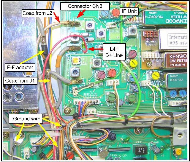
3 3. Remove the Inrad roofing filter from its packing. 4. Strip 1/8 from each end of the red and black wires. 5. Solder the red wire to the pad marked +12V on the Inrad board. 6. Solder the black wire to the pad marked GND. 7. Insert the 2 mounting posts into the holes in the Inrad PC board. Insert one coax cable into J1 and the other into J2. Set aside. 8. Locate the space between the signal board and the front panel that the mod will be mounted in. See Figure Lift the lock on the ribbon cable connector, CN1 and pull the cable end out. 10. Lift the multicolored cable. Using the supplied solid wire, temporarily tie the cables out of the way. 11. Before removing the nonstick papers from the mounting posts, put the mod in place as shown. Note that J2 should be to the left of CN When you are sure that you have found the correct position, remove the nonstick papers and insert the mod. Press the mounts in place. 13. Position the red, black and two coax wires over the signal unit and through the opening in the shield to the IF unit. Use two tie wraps over the signal unit. 14. Unplug the OEM coax from CN6 on the IF unit. Insert the coax from J2 on the mod into CN Insert the coax from CN6 into the double female coax adapter (supplied). 16. Plug the coax from J1 on the mod into the other side of the double female coax adapter. 17. Mount the solder lug under the gold screw in the corner of the signal unit, close to where the mod wires go through the chassis opening to the IF board. Use care not to short any traces with the lug. 18. Double the black wire back and carefully solder to the lug. 19. Locate L41 near CN5 on the IF board. Carefully solder the red wire onto the end of L41 closest to the front panel. This provides +15V. 20. Place the ribbon cable back into connector CN1 and lock. Before pressing the lock down, make sure the cable is fully seated by rocking it carefully from side to side. 21. Dress the wires neatly by tucking them into the metal slot between the IF UNIT and SIGNAL UNIT and carefully replace the bottom cover, making sure that none of the wires gets pinched. This completes the installation. Parts List Assembled Inrad-117 board 2 Coax cables 12 M-M 1 Coax adapter F-F 2 Board mounts Red and black #24 wire-15 each 1 Solder lug 1 piece of solid wire 6 2 Tie wraps 2008 International Radio Corporation - 3 -

4 FIGURE International Radio Corporation - 4 -
5 FIGURE 4 +15V 78L05 C7 C2 J1 FL MHz Xtal Filter R1 C1 C3 R6 Q1 Q2 L1 C6 J2 R2 C4 C5 R3 R4 R5 C1,2,3,4,5,6 0.1uF C7 0.47uF L1 2.2uH R1 3.9K R2 2.2K R3,4 68 R5 12 R6 220 Q1,2 MPS5179 TS 950S/SD/SDX Roofing Filter Mod W2VJN 1/12/ International Radio Corporation - 5 -
IC-765: Installing the Inrad Roofing Filter Mod
 IC-765: Installing the Inrad Roofing Filter Mod The Icom IC-765 roofing filter mod consists of a 6-pole, 4 khz wide filter followed by a high dynamic range, feedback amplifier. The amplifier provides enough
IC-781: Installing the Inrad Roofing Filter Mod
 IC-781: Installing the Inrad Roofing Filter Mod The Icom IC-781 roofing filter mod consists of a 6-pole, 4 to 5 khz wide filter followed by a high dynamic range, feedback amplifier. The amplifier provides
TS-870: Installing the Inrad Roofing Filter Mod
 TS-870: Installing the Inrad Roofing Filter Mod The TS-870 roofing filter mod consists of a 6 pole, 4 to 5 khz wide filter followed by a high dynamic range feedback amplifier. The amplifier provides enough
TS-850: Installing the Inrad Roofing Filter Mod
 TS-850: Installing the Inrad Roofing Filter Mod The TS-850 Roofing Filter Mod consists of a 6 pole, 4 to 5 khz wide filter followed by a high dynamic range feedback amplifier. The amplifier provides enough
TS-930: Installing the Inrad Roofing Filter Mod
 TS-930: Installing the Inrad Roofing Filter Mod The TS-930 roofing filter mod consists of a 6 pole, 4 to 5 khz wide filter followed by a high dynamic range, feedback amplifier. The amplifier provides enough
INTERNATIONAL RADIO CORP
 I N R A D INTERNATIONAL RADIO CORP 13620 Tyee Road Umpqua, OR 97486 (541) 459-5623 fax (541) 459 5632 E-mail: inrad@rosenet.net www.qth.com/inrad IC-775 ROOFING FILTER INSTALLATION INSTRUCTIONS The IC-775
Beta-test ED1 PCB installed in I0CG s K1
 K1 SSB Modification (Ed.2) This description provides the receiver (RX) modifications, assembly, alignment and operation as a first step. In a second step you can add the remaining transmitter (TX) modifications,
DRM Receive Conversion for Yaesu FT920 HF Transceiver by Don M0DKS
 1. Introduction This conversion describes the addition of the DRM receive function for a Yaesu FT920 HF Transceiver that is equipped with the FM-1 optional FM transceive board. The FT920 is a double hetrodyne
Manual AMERITRON QSK-5PC T/R SWITCH PC BOARD INTRODUCTION
 Manual Instruction AMERITRON QSK-5PC T/R SWITCH PC BOARD INTRODUCTION The Ameritron QSK-5PC is a PIN diode QSK circuit board designed for use in Ameritron's AL-80A, AL-80B, AL-82, AL-1500 and AL- 1200
ELECRAFT Application Note
 ELECRAFT Application Note Front Panel Microphone Circuit Modification Revision A, November 12, 2008 Copyright 2008, Elecraft, Inc., All Rights Reserved Background Some K3 owners have noted distorted transmit
Ten-Tec Orion Sub Receiver VHF Filter Modification Prepared by Rick Williams, VE7TK
 Ten-Tec Orion Sub Receiver VHF Filter Modification Prepared by Rick Williams, VE7TK (Note: Those undertaking this modification do so at their own risk. The procedures outline a method of installing an
huprf Panoramic Adaptor Installation FT847
 huprf Panoramic Adaptor Installation FT847 These instructions cover installation of the PAT board in the 1st IF of the FT847 45.705MHz this gives access to all receiver options on the main receiver. A
Step by Step Building PJ meter ARDF Receiver Kit. CRKITS.COM August 5, 2013
 Step by Step Building PJ-80 80-meter ARDF Receiver Kit CRKITS.COM August 5, 2013 What is ARDF? ARDF is the abbreviation of Amateur Radio Direction Finding, or so called Fox Hunting. If you are looking
DEM Part Number L144-28INTCK 144 MHz Transverter Kit and complete kit
 DEM Part Number L144-28INTCK 144 MHz Transverter Kit and complete kit Power Out: Noise Figure and Gain: DC Power Requirement: 50 mw linear minimum 3.5 db NF nominal, 5 dbg maximum 12-15.5 VDC, 13.8 nominal
NOTE: The 1-piece panel is required for installation (the face mounts to the panel).
.") Installation Notes Flush Wood Plus Cypress Face Installation Before installing, make sure to install the one-piece panel, and disconnect the power cords making sure the Molex connector and two wires are
Installation Notes Flush Wood Plus Cypress Face Installation Before installing, make sure to install the one-piece panel, and disconnect the power cords making sure the Molex connector and two wires are
MPC-XU Universal Crossover
 MPC-U Universal Crossover For JBL MPC and MPA amplifiers Owner s Manual and Installation Guide I. Description The MPC-U is a dual-channel universal crossover filter accessory for use with JBL MPC and MPA
12kHz LIF Converter V2.43 9Mhz version
 12kHz LIF Converter V2.43 9Mhz version Please Note: This document supersedes all previously released documents and drawings on the LIF subject. This is the latest and most up-to-date document at this time.
Treetop Circuits Owner s Manual for SB-SB-600 Adapter Version 1
 The SB-600 SSB adapter from Treetop Circuits (Fig. 1) is designed specifically as an accessory to the Hammarlund SP-600 series of receivers. It provides enhanced performance on SSB and CW signals, using
W4RT Electronics A Division of CyberAir Development Corporation 22 March For the Yaesu FT-817 & FT-817ND
 W4RT Electronics A Division of CyberAir Development Corporation www.w4rt.com 22 March 2005 For the Yaesu FT-817 & FT-817ND The ONE BOARD FILTER (OBF-817) is an accessory for the YAESU FT-817 and FT-817ND.
Improving the Performance of the KSB2
 Introduction Improving the Performance of the KSB2 John Grebenkemper, KI6WX KI6WX@pacbell.net July 18, 2002 The following is a set of changes that I have done to my KSB2 and related circuits to improve
Stereo Clipper 15KHz LPF. Stereo audio clipper with active 15KHz filters
 Stereo Clipper 15KHz LPF Stereo audio clipper with active 15KHz filters Dimension (L x W x H): 62mm x 50mm x 15mm FMB stereo audio clipper with active 15KHz filters, is an audio board with professional
HF Receivers, Part 2
 HF Receivers, Part 2 Superhet building blocks: AM, SSB/CW, FM receivers Adam Farson VA7OJ View an excellent tutorial on receivers NSARC HF Operators HF Receivers 2 1 The RF Amplifier (Preamp)! Typical
MARTIN - G8JNJ ECLECTIC AETHER - ADVENTURES WITH AMATEUR RADIO
 MARTIN - G8JNJ ECLECTIC AETHER - ADVENTURES WITH AMATEUR RADIO REDUCING RTL DONGLE INTERNAL SPURII AND NOISE SIGNALS I ve recently bought quite a few RTL DVB-T RTL 2832U / Rafael Micro R820T dongles to
TEN-TEC Orion (Model 565 and 566) 9 MHz IF Output
 9 MHz IF Output") TEN-TEC Orion (Model 565 and 566) 9 MHz IF Output Prepared by Rick Williams, VE7TK (Note: Those undertaking this modification do so at their own risk. The procedures outlined provided a 9 MHz IF output
TEN-TEC Orion (Model 565 and 566) 9 MHz IF Output Prepared by Rick Williams, VE7TK (Note: Those undertaking this modification do so at their own risk. The procedures outlined provided a 9 MHz IF output
Sixty Meter Operation with Modified Radios
 Sixty Meter Operation with Modified Radios The following pages document the results of 6-meter transmitter performance on a group of transceivers that have been modified to enable operation on the sixty-meter
POWER AMPLIFIER. Owner s Manual Mode d emploi Bedienungsanleitung Manual de instrucciónes CLIP SIGNAL TEMP PROTECTION POWER
 POWER AMPLIFIER Owner s Manual Mode d emploi Bedienungsanleitung Manual de instrucciónes TEMP PROTECTION POWER A CLIP SIGNAL B ON OFF M Introduction Thank you for purchasing a Yamaha C450/320/160 series
MODEL FS-4 INSTRUCTION MANUAL R.L. DRAKE COMPANY, MIAMISBURG, OHIO, U.S.A.
 MODEL FS-4 F R E Q U E N C Y S Y N T H E S I Z E R INSTRUCTION MANUAL R.L. DRAKE COMPANY, MIAMISBURG, OHIO, U.S.A. LIMITED WARRANTY R. L. DRAKE COMPANY warrants to the original purchaser that this product
TK-931 Receiver Modifications
 TK-931 Receiver Modifications This page identifies all the hardware modifications necessary to adapt a Kenwood TK-931 transceiver for 902 MHz repeater receive operation. Not shown here is the effort required
TS-480 Replacing the standard MCF (monolithic crystal filter)
") TS-480 Replacing the standard MCF (monolithic crystal filter) The TS-480 has a monolithic crystal filter installed in the second IF (10,695 MHz). This is a 2,4 khz filter which is used on both RX and TX
TS-480 Replacing the standard MCF (monolithic crystal filter) The TS-480 has a monolithic crystal filter installed in the second IF (10,695 MHz). This is a 2,4 khz filter which is used on both RX and TX
C.M.HOWES COMMUNICATIONS CTU150 Instructions
 CTU150 Instructions The HOWES CTU150 is an antenna matching unit for use with shortwave transmitters and receivers. A novel constructional method is used - all parts being mounted on a Printed Circuit
Dual Band Filter Assembly Manual
 Dual Band Filter Assembly Manual 12 January 2018 Rev D Version Theory of Operation: The purpose of a Bandpass Filter is to filter out or reject all unwanted signals. The original KN-Q7A Receive Filter
HAMTRONICS TB901 FM EXCITER INSTALLATION, OPERATION, & MAINTENANCE
 HAMTRONICS TB901 FM EXCITER INSTALLATION, OPERATION, & MAINTENANCE GENERAL INFORMATION. The TB901 is a single-channel low power fm transmitter (exciter) designed to provide 300-600 milliwatts continuous
RadiØKit Μ CW HAM RADIO TRANSCEIVER KIT. Assembly and operating manual
 RadiØKit-120 20Μ CW HAM RADIO TRANSCEIVER KIT Assembly and operating manual Boreiou Ipirou 78 Kolonos Athens- Greece - 10444 Tel: 210.5150527 210.5132673 www.freebytes.com Thank you for buying RadiØKit-1,
Assembly Instructions for the 1.5 Watt Amplifier Kit
 Assembly Instructions for the 1.5 Watt Amplifier Kit 1.) All of the small parts are attached to a sheet of paper indicating both their value and id. 2.) Leave the parts affixed to the paper until you are
HT-1A Dual Band CW QRP Transceiver. Kit Building Instructions
 HT-A Dual Band CW QRP Transceiver Kit Building Instructions Rev B, July 8, 08 Designed by BD4RG Exclusively distributed by CRKITS.COM and its worldwide distributors Join the group http://groups.io/g/crkits
Assembly Instructions for the FRB FET FM 70 Watt Amp
 Assembly Instructions for the FRB FET FM 70 Watt Amp 1.) Orient the circuit board with the diagram 2.) Use a narrow chisel tip 25-30 watt soldering iron for assembly 3.) All the small parts are taped onto
Yaesu FT-1000MP Mark V and NaP3
 Yaesu FT-1000MP Mark V and NaP3 This paper describes in detail the hardware and software required to implement a full-function panadaptor for the Mark V using NaP3. Illustration 1: Panadaptor in operation
Array Solutions 350 Gloria Rd Sunnyvale, TX USA PHN FAX
 Array Solutions 350 Gloria Rd Sunnyvale, TX 75182 USA PHN 972 203 2008 FAX 972 203 8811 E-MAIL sales@arraysolutions.com Model AS-AYL-4 4-way K9AY Loop System This is the popular K9AY Loop receiving antenna,
Guide to Installing the Splash guard and two piece shield on the ASX-520 and ASX-520HS Autosamplers
 Guide to Installing the Splash guard and two piece shield on the ASX-520 and ASX-520HS Autosamplers This guide describes the necessary steps for installing the splash guard and two piece shield on the
Receiver Performance. Roofing Filters, Rob Sherwood NCØB. What s important when it comes to. choosing a radio? Sherwood Engineering
 Roofing Filters, Transmitted IMD and Receiver Performance Rob Sherwood NCØB What s important when it comes to choosing a radio? Sherwood Engineering 1 2 Why Did I Start Testing Radios? Purchased a new
Manual Version July 2007
 Manual Version 1.2 - July 2007 Page 1 Table of Contents Section1: M3 Phono Board Build...3 Phono Board Parts List...3 Preparation...4 Fitting the Valve Bases...6 Installing the Resistors...7 Starting the
INSTALLATION AND OPERATING MANUAL
 INSTALLATION AND OPERATING MANUAL FOR RBDA-PCS-1/25W-90-A INDOOR REPEATER TABLE OF CONTENTS PARAGRAPH PAGE NO BDA OVERVIEW 3 BDA BLOCK DIAGRAM DESCRIPTION 3 FCC INFORMATION FOR USER 3 BDA BLOCK DIAGRAM
E L E C R A F T K N B 1 N O I S E B L A N K E R
 Introduction E L E C R A F T K N B N O I S E B L A N K E R Assembly and Operating Instructions Revision C, Jan. 8, 200. Copyright 200, Elecraft; All Rights Reserved The KNB noise blanker can be used to
Introduction...2. Purpose... 2 Revision history... 2 Related documentation... 2 Preventing electrostatic discharge damage... 2
 Wireless Transceiver Upgrade Instructions for AlphaEclipse 3600 Signs For the most recent update, go to http://www.adaptivedisplays.com/support/eclipse. Locus OS2400-232 2.4GHz wireless transceiver Alpha
User Guide for the Alpha Loop Sr Antenna
 User Guide for the Alpha Loop Sr Antenna Manufactured by: Alpha Antenna 1.888.482.3249 Website: http://alphaantenna.com Available from: Amateur Radio Store Website: https://amateurradiostore.com User Guide
Lumewave and LumInsight IoT. Gateway and Base Station Installation Guide
 Lumewave and LumInsight IoT Gateway and Base Station Installation Guide P/N 055-0121-01B 8/9/2018 Contents Installation Planning 3 Gateway Types 3 Gateways 4 Base Stations 4 Antenna Specification 4 Antenna
WA3RNC 30 METER CRYSTALPLEXER TRANSMITTER KIT ASSEMBLY INSTRUCTIONS
 WA3RNC 30 METER CRYSTALPLEXER TRANSMITTER KIT ASSEMBLY INSTRUCTIONS Description The WA3RNC 30 Meter Crystalplexer is a low power crystal controlled QRP transmitter offering a significantly improved tuning
Transceiver selection and Specs.
 Transceiver selection and Specs. Transceivers 1956-2018 From TUBES to SDR Covers 20-10 meters in 100Khz segments, 10 available, crystal needed for each. Plug in crystal holder. 100 Watts output, final
huprf Panoramic Adaptor Installation IC718
 Panoramic Adaptor Installation IC718 These instruction cover installation of the PAT board in the 1st IF of the ICOM IC718 64.455MHz this gives access to all receiver options on the main receiver. Although
ALX-SSB 5 Band Filter Assembly Manual 19 November 2018
 ALX-SSB 5 Band Filter Assembly Manual 19 November 2018 Contents Theory of Operation:... 1 Figure 1... 2 Parts Included:... 4 Board Overview:... 5 Figure 2... 5 Figure 3... 5 Board Assembly:... 6 Cable
Lead Screw Upgrade. How to upgrade your ROBO R1 to the new Lead Screw Upgrade Pack. Written By: Harrison Team RoBo 3D
 Lead Screw Upgrade How to upgrade your ROBO R1 to the new Lead Screw Upgrade Pack. Written By: Harrison Team RoBo 3D 2017 guide.robo3d.com Page 1 of 14 Step 1 Lead Screw Upgrade Begin by powering off and
GRAND STRAND AMATEUR RADIO CLUB
 The GRAND STRAND AMATEUR RADIO CLUB (GSARC) Myrtle Beach SC is offering used amateur related equipment for sale. Written bids may be submitted to the GSARC up to Friday, November 23 rd, 2018. Only currently
ScreenLogic Wireless Connection Kit. Installation Guide. pool/spa control system
 pool/spa control system ScreenLogic Wireless Connection Kit Installation Guide P/N 520663 - Rev A 8 Technical Support Contact Technical Support at: Sanford, North Carolina (8 A.M. to 5 P.M.) Phone: (800)
Cisco Aironet Omnidirectional Mast Mount Antenna (AIR-ANT2506)
") Cisco Aironet Omnidirectional Mast Mount Antenna (AIR-ANT2506) This document outlines the specifications, describes the omnidirectional mast mount antenna, and provides instructions for mounting it. Designed
Cisco Aironet Omnidirectional Mast Mount Antenna (AIR-ANT2506) This document outlines the specifications, describes the omnidirectional mast mount antenna, and provides instructions for mounting it. Designed
VLF-LF-MF Up Converter
 VLF-LF-MF Up Converter 5kHz-500kHz 3.5MHz-4MHz model 350 4MHz-4.5MHz model 400 User manual. Rev 2018-01 Since many countries are allocating the 472 khz to 479kHZ band for experimental use by Radio Amateurs,
User Guide for the Alpha QRP Loop Antenna
 User Guide for the Alpha QRP Loop Antenna Manufactured by: Alpha Antenna 1.888.482.3249 Website: http://alphaantenna.com User Guide Version 2.0 Page 1 Table of Contents Introduction... 3 Product Overview...
Improved Ionospheric Propagation With Polarization Diversity, Using A Dual Feedpoint Cubical Quad Loop
 Improved Ionospheric Propagation With Polarization Diversity, Using A Dual Feedpoint Cubical Quad Loop by George Pritchard - AB2KC ab2kc@optonline.net Introduction This Quad antenna project covers a practical
Step- by- Step Assembly Instructions (with photos)
") Step- by- Step Assembly Instructions (with photos) Page Unpack the Photo Booth... 2 Secure the Power Cord... 3 Install the Camera Topper... 4 Load Paper into the Printers... 8 Load the Ink Film and Ink
Step- by- Step Assembly Instructions (with photos) Page Unpack the Photo Booth... 2 Secure the Power Cord... 3 Install the Camera Topper... 4 Load Paper into the Printers... 8 Load the Ink Film and Ink
HAMTRONICS R451 UHF FM RECEIVER: INSTALLATION, OPERATION, & MAINTENANCE
 HAMTRONICS R451 UHF FM RECEIVER: INSTALLATION, OPERATION, & MAINTENANCE FUNCTIONAL DESCRIPTION. The R451 is a premium, commercial- grade single-channel uhf fm receiver. It features a GaAs FET rf amplifier
Progeny Integrated Mobile Unit Unpacking/Assembly Guide
 Summary: The following instruction will guide you through the unpacking and installation of the Progeny Mobile Unit. Any question or concerns or suggestions should be directed to Progeny Technical Support
IC-756 Pro III vs. Pro II
 IC-756 Pro III vs. Pro II Improvements in the Pro III vs. the Pro II Adam Farson VA7OJ IC-756Pro3 Information & Links Copyright 2006 North Shore Amateur Radio Club NSARC HF Operators 756Pro3 vs. Pro2 1
HAMTRONICS R100 VHF FM RECEIVER: ASSEMBLY, INSTALLATION, OPERATION, & MAINTENANCE
 HAMTRONICS R100 VHF FM RECEIVER: ASSEMBLY, INSTALLATION, OPERATION, & MAINTENANCE Note about page numbers. In order to accommodate various bands, this manual has extra pages you may not receive for your
PRX4SERL Four Zone Receiver Decoder
 PRX4SERL Four Zone Receiver Decoder Operating Manual Microframe Corporation 604 S. 12 th Street Broken Arrow, OK 74012 Tel: (918) 258-4839 Toll Free: 1-800-635-3811 Website: www.microframecorp.com E-mail:
Broadband Power Amplifier
 601L Broadband Power Amplifier HIGH RF VOLTAGES MAY BE PRESENT AT THE OUTPUT OF THIS UNIT. All operating personnel should use extreme caution in handling these voltages and be thoroughly familiar with
Installation Instructions
 Installation Instructions Optima LED 8 Double-Sided StretchLite Perimeter Lit Graphic Display Line Voltage Connector Optima LED DS5 (Double-sided StretchLite Graphic Display) with Graphics Corner Bracket
Single Channel Radio Mic System USER MANUAL. WMU-116-H (Hand Held) WMU-116-B (Belt Pack) Single Channel Radio Mic System
 WMU-116-B (Belt Pack) Single Channel Radio Mic System") Single Channel Radio Mic System USER MANUAL WMU-116-H (Hand Held) WMU-116-B (Belt Pack) Single Channel Radio Mic System Welcome Thank you for choosing Hill Audio for your sound system. To make sure that
Single Channel Radio Mic System USER MANUAL WMU-116-H (Hand Held) WMU-116-B (Belt Pack) Single Channel Radio Mic System Welcome Thank you for choosing Hill Audio for your sound system. To make sure that
SoftRock v6.0 Builder s Notes. April 6, 2006
 SoftRock v6.0 Builder s Notes April 6, 006 Be sure to use a grounded tip soldering iron in building the v6.0 SoftRock circuit board. The soldering iron needs to have a small tip, (0.05-0. inch diameter),
1 GHz SASMAX II series
 1 GHz SASMAX II series SASMAX II Line Extender (Legacy LEII style) Description: The 1 GHz SASMAX II series broadband line extender is essentially a drop-in-upgrade module that allows the customer to perform
UNIVERSAL-DDS-VFO UDV ( 1 Hz to 10 MHz)
") UNIVERSAL-DDS-VFO UDV ( 1 Hz to 10 MHz) Connection and operating instructions 1. Introduction The UDV is the ideal device to adapt older, VFO-controlled transceivers to modern requirements regarding frequency
UNIVERSAL-DDS-VFO UDV ( 1 Hz to 10 MHz) Connection and operating instructions 1. Introduction The UDV is the ideal device to adapt older, VFO-controlled transceivers to modern requirements regarding frequency
QUICK REFERENCE GUIDE
 QUICK REFERENCE GUIDE Installation 1. Install a ground system for DC noise suppression and RFI suppression 2. Install your DC power supply 3. Install lightning protection. This will help protect more than
Antenna Disconnect THE INEXPENSIVE WAY TO PROTECT YOUR VALUABLE RADIO FROM LIGHTNING SURGES
 Antenna Disconnect THE INEXPENSIVE WAY TO PROTECT YOUR VALUABLE RADIO FROM LIGHTNING SURGES -------------------------------------------------------------------------------------- Operating Manual May 2017
Installation... 3 Installing The Radio... 3 Ignition Noise Interference... 4 Antenna... 4 External Speaker... 4 Public Address...
 TABLE OF CONTENTS CHAPTER 1 Specifications.............................................. 2 PAGE BIG RIG SERIES S 1 MOD PW R 20 0 3 SW R 40 1 5 5 60 1.5 7 10 2 9 20 80 3 30 +20 40 50 +40 100% MAX db +60
SUBELEMENT T4. Amateur radio practices and station set up. 2 Exam Questions - 2 Groups
 SUBELEMENT T4 Amateur radio practices and station set up 2 Exam Questions - 2 Groups 1 T4A Station setup: connecting microphones; reducing unwanted emissions; power source; connecting a computer; RF grounding;
CON NEX HP. OWNER'S MANUAL Full Channel AM/FM Amateur Mobile Transceiver TABLE OF CONTENTS TUNING THE ANTENNA FOR OPTIMUM S.W.R..
 TABLE OF CONTENTS PAGE SPECIFICATIONS... 2 INSTALLATION... 3 LOCATION... 3 CON NEX - 4300HP MOUNTING THE RADIO... 3 IGNITION NOISE INTERFERENCE... 4 ANTENNA... 4 TUNING THE ANTENNA FOR OPTIMUM S.W.R..
ALM473 DUAL MONO \ STEREO AUDIO LEVEL MASTER OPERATION MANUAL IB
 ALM473 DUAL MONO \ STEREO AUDIO LEVEL MASTER OPERATION MANUAL IB6408-01 TABLE OF CONTENTS GENERAL DESCRIPTION 2 INSTALLATION 2,3,4 CONNECTION AND SETUP 4,5,6,7 FUNCTIONAL DESCRIPTION 8,9 MAINTENANCE 9
On-Line Cardio Theater Wireless Digital Transmitter Installation and Instruction Manual
 On-Line Cardio Theater Wireless Digital Transmitter Installation and Instruction Manual Full installation instructions accompany your Cardio Theater equipment order. This On-Line version of our Installation/Instruction
Icom IC-9100 HF/VHF/UHF transceiver
 263 Walsall Road, Great Wyrley, Walsall, WS6 6DL Established 1997. Open Monday - Friday 9am - 5pm and Saturday 9.30am - 4pm Tel: 01922 414 796 Fax: 01922 417829 Skype: radioworld_uk Icom IC-9100 HF/VHF/UHF
18-CHANNEL MOBILE CB TRANSCEIVER MODEL CB-845
 18-CHANNEL MOBILE CB TRANSCEIVER MODEL CB-845 INSTRUCTION HANDBOOK RAll JEFFERSOn CITIZEN BAND RADIO MESSAGE TO THE OWNER CONGRATULATIONS! As the new owner of Ray Jefferson Model CB-845 CB Mobile Transceiver,
Radio Receivers. Al Penney VO1NO
 Radio Receivers Al Penney VO1NO Role of the Receiver The Antenna must capture the radio wave. The desired frequency must be selected from all the EM waves captured by the antenna. The selected signal is
VLF-LF Up Converter 5KHz - 500KHz. User manual. Rev HEROS technology Limited All rights reserved
 VLF-LF Up Converter 5KHz - 500KHz User manual. Rev 2016-02 Since many countries are allocating the 472 khz to 479kHZ band for experimental use by Radio Amateurs, a growing number of them as well as listeners
HAMTRONICS R144 VHF FM RECEIVER, REV. 4/94: INSTALLATION AND MAINTENANCE
 HAMTRONICS R144 VHF FM RECEIVER, REV. 4/94: INSTALLATION AND MAINTENANCE FUNCTIONAL DESCRIPTION. The R144 is a premium commercial grade single-channel vhf fm receiver. It features a helical resonator front
RCI-6300F25/150. Owner's Manual. AM/FM Amateur Transceiver With Built-in Frequency Counter. Table of Contents. Downloaded from
 Table of Contents RCI-6300F25/150 AM/FM Amateur Transceiver With Built-in Frequency Counter PAGE Chapter 1 Specifications...... 2 Chapter 2 Installation...... 3 Installing the Radio... 3 Ignition Noise
The Uniden Grant XL Owners Site
 The Uniden Grant XL Owners Site Modifications page for the Grant XL (For Informational purposes only) The author of this site takes NO responsibility for illegal modifications and/or use of illegally modified
Model AAA-1C. Addendum to AAA-1B documentation
 Model AAA-1C. Addendum to AAA-1B documentation 1. Specifications for Model AAA-1C (11) General Output impedance Power supply (1) Maximal output voltage (10) Physical size 50 Ohms, BNC connector on control
Assembly and Installation Instructions for White Oak Audio Design PL400 Series 1 LED board
 Thank you for purchasing White Oak Audio Design s Phase Linear PL400 Upgrade LED Light Board. White Oak Audio Design products are meticulously engineered and tested to ensure a direct drop in fit with
Dual, Current Feedback Low Power Op Amp AD812
 a FEATURES Two Video Amplifiers in One -Lead SOIC Package Optimized for Driving Cables in Video Systems Excellent Video Specifications (R L = ): Gain Flatness. db to MHz.% Differential Gain Error. Differential
IMMS-R. IMMS-R Radio Module. Installation Instructions POWER. Controller. Comm.
 IMMS-R IMMS-R Radio Module Installation Instructions TABLE OF CONTENTS... Before you install... 1 Key Specifications... 2 Important Installation notes... 3 Installation... 3 Interface Installation... 4
Assembly Instructions
 Assembly Instructions For the SSQ-2F 3.1 MHz Rife Controller Board Kit v1.41 Manual v1.00 2012 by Ralph Hartwell Spectrotek Services GENERAL ASSEMBLY INSTRUCTIONS Arrange for a clean work surface with
Roofing Filters, Transmitted BW and Receiver Performance
 Roofing Filters, Transmitted BW and Receiver Performance Rob Sherwood NCØB What s important when it comes to choosing a radio? Sherwood Engineering Why Did I Start Testing Radios? Purchased a new Drake
SOHO Mobile Repeater USER GUIDE
 SOHO Mobile Repeater USER GUIDE Powertec Telecommunications Pty Ltd 14/511OlsenAvenue SouthportQld4215 Australia Ph:+61755770500 Email: sales@powertec.com.au www.powertec.com.au SOHO Repeater User Guide
FIELD REPLACEABLE UNIT DOCUMENTATION
 GENERAL INFORMATION Tools Required for Proper Disassembly and Reassembly: 1. Phillips Screwdriver (Size0&1) 2. 4mm Flat head Screwdriver 3. Case Separator 4. ESD Wrist Strap 5. ESD mats 6. Tweezers Before
Appendix A: BLC-10/20/25 DC Models Packing
 Appendix A: BLC-10/20/25 DC Models Packing List BLC-10/20/25/40/50 User Manual Appendix A: BLC-10/20/25 DC Models Packing List Description Belcom P/N Quantity BLC-10/20/25 BLC 10/20/25 1 Installation Kit,
Hardware Store 40m Magnetic Loop Antenna for Regional and EMCOM Use. Richard Bono NO5V. QST Antenna Design Competition 80 through 10 meter entry
 Hardware Store 40m Magnetic Loop Antenna for Regional and EMCOM Use Richard Bono NO5V QST Antenna Design Competition 80 through 10 meter entry Overview: This describes a field deployable magnetic loop
the radio grounds switched
 Clansman PRC 351 Modification to operatee radio on 10m band Introduction The Clansman PRC 351 is a man portable radio with a maximum output power of approx. 4W and an operating frequency range of 30.000MHz
ICOM M710 FIX for PC-ALE USE
 ICOM M710 FIX for PC-ALE USE Tony Rycko KA2UFO R0.1 9/8/2018 DRAFT FOR REVIEW Tony Rycko KA2UFO Page 1 Introduction The ICOM M710 Marine HF Radio in stock configuration is not suitable for PC-ALE use.
WJ 8617B and 8618B 10 KHz IF Bandwidth Upgrade By: Stephen Pappin
 WJ 8617B and 8618B 10 KHz IF Bandwidth Upgrade By: Stephen Pappin Many early 8617Bs and 8618Bs were configured with 20 KHz IF filters in bandwidth position 1. This bandwidth is suitable for A9W Composite
Instructions MODIFICATION KIT MODEL SBM - 1O2-1 INTRODUCTION PARTS LIST FOR THE
 Instructions FOR THE MODIFICATION KIT MODEL SBM - 1O2-1 INTRODUCTION This modification Kit applies to the following Heath Transceivers: 1. All Models HW-100, SB-100, SB-101 and SB-101W. 2. Any Model SB-102
Series IV Pro-Connect Baluns. Set-Up Guide
 Series IV Pro-Connect Baluns PCBKDCOVAAB, PCBKDCOVDAB, PCBKDCOVIRB, PCBKDCOVSAB Set-Up Guide PCBKDCOVAAB PCBKDCOVIRB PCBKDCOVDAB PCBKDCOVSAB Key Digital Pro-Connect Series Baluns; PCBKDCOVAAB Component
Harmony Remote Repair
 Harmony Remote Repair harmonyremoterepair.com How to install your new Harmony One Front Cover/Touch Screen Important! Before you begin working on your Harmony One, you must discharge any static electricity
Written By: Walter Galan
 Xbox 360 CPU Heat Sink Replacement CPU heat sink replacement. Written By: Walter Galan ifixit CC BY-NC-SA www.ifixit.com Page 1 of 27 INTRODUCTION Use this guide to remove the CPU heat sink from your Xbox