Low-Voltage Power Distribution and Electrical Installation Technology
|
|
|
- Loren Paul
- 5 years ago
- Views:
Transcription


1 Busbar trunking system Installation Manual 06/2011 Low-Voltage Power Distribution and Electrical Installation Technology Answers for infrastructure.
2
3 SIVACON 8PS - Installation with LX system Low-voltage power distribution and electrical installation technology Busbar trunking system SIVACON 8PS - Installation with LX system Installation Manual Introduction 1 Planning usage 2 Installation 3 Commissioning 4 Service and maintenance 5 Weights 6 Test reports 7 06/2011 A5E
4 Legal information Legal information Warning notice system This manual contains notices you have to observe in order to ensure your personal safety, as well as to prevent damage to property. The notices referring to your personal safety are highlighted in the manual by a safety alert symbol, notices referring only to property damage have no safety alert symbol. These notices shown below are graded according to the degree of danger. DANGER indicates that death or severe personal injury will result if proper precautions are not taken. WARNING indicates that death or severe personal injury may result if proper precautions are not taken. CAUTION with a safety alert symbol, indicates that minor personal injury can result if proper precautions are not taken. CAUTION without a safety alert symbol, indicates that property damage can result if proper precautions are not taken. NOTICE indicates that an unintended result or situation can occur if the relevant information is not taken into account. If more than one degree of danger is present, the warning notice representing the highest degree of danger will be used. A notice warning of injury to persons with a safety alert symbol may also include a warning relating to property damage. Qualified Personnel The product/system described in this documentation may be operated only by personnel qualified for the specific task in accordance with the relevant documentation, in particular its warning notices and safety instructions. Qualified personnel are those who, based on their training and experience, are capable of identifying risks and avoiding potential hazards when working with these products/systems. Proper use of Siemens products Note the following: WARNING Siemens products may only be used for the applications described in the catalog and in the relevant technical documentation. If products and components from other manufacturers are used, these must be recommended or approved by Siemens. Proper transport, storage, installation, assembly, commissioning, operation and maintenance are required to ensure that the products operate safely and without any problems. The permissible ambient conditions must be complied with. The information in the relevant documentation must be observed. Trademarks All names identified by are registered trademarks of Siemens AG. The remaining trademarks in this publication may be trademarks whose use by third parties for their own purposes could violate the rights of the owner. Disclaimer of Liability We have reviewed the contents of this publication to ensure consistency with the hardware and software described. Since variance cannot be precluded entirely, we cannot guarantee full consistency. However, the information in this publication is reviewed regularly and any necessary corrections are included in subsequent editions. Siemens AG Industry Sector Postfach NÜRNBERG GERMANY A5E P 06/2011 Copyright Siemens AG Technical data subject to change
5 Table of contents 1 Introduction Introduction Planning usage Scope of delivery Receiving goods Safe handling Storage Packaging Handling Installation Overview Installing a busbar run Installation recommendations Attaching fixing material Overview Bracket for horizontal installations Spring brackets for vertical installation on walls Floor fixing for spring brackets Fixing brackets with fixed point for vertical installation Connecting units Joining elements by joining the ends together Connection from above Expansion unit Flanged end Flanged end Storage prior to installation Transport and handling at the installation location Installation Handling if multiple busbar runs are laid in parallel Transformer connection Transformer connection unit Storage prior to installation Transport on-site Positioning the transformer connection unit above the transformer Attaching the transformer connection unit at the installation location Handling if multiple busbar runs are laid in parallel...43 Installation Manual, 06/2011, A5E
6 Table of contents 3.9 Fire barrier Fire barrier regulations Installation of MOS fire barrier Tap-off unit Tap-off units from 50 A to 630 A Tap-off units from 800 A to 1,250 A Lateral mounting of tap-off units above 400 A in runs for horizontal installation Commissioning Steps to be performed prior to electrification of the line Electrifying the line Service and maintenance Dismantling a busbar trunking system element in a horizontal line Dismantling a busbar trunking system element in a vertical line Dismantling joint blocks Reassembling joint blocks Weights Test reports Test report for inspecting assembled joint blocks on initial assembly Test report for inspecting assembled joint blocks on subsequent assembly Insulation test report Installation Manual, 06/2011, A5E
7 Introduction Introduction This manual is designed to assist you in installing, maintaining and commissioning LX systems. Note Before installing the system on the site, you must read and follow the instructions on storage, transport and handling. WARNING Only personnel who have been trained in site safety regulations (such as the wearing of helmets, safety goggles, safety shoes, high-visibility tabards, etc.) may work on construction sites and install busbar trunking systems. The responsible safety officer must provide mandatory safety training. Manual overview This manual consists of four sections: General information: Brief overview of busbar trunking system components and how they are installed Installation: Description of how the busbar trunking system elements are installed Inspection, expansions, checks: Description of how to handle the busbar trunking system once it has been installed Checklists and reports You can find more detailed technical information on LX systems in the planning manual "Planning with SIVACON 8PS" (Order number A5E ). In addition, observe the installation instructions for the individual busbar elements. The installation instructions contain specific details on how to install the various busbar elements. You can find an overview of the installation instructions at Installing a busbar run (Page 13). Installation Manual, 06/2011, A5E
8 Introduction 1.1 Introduction 6 Installation Manual, 06/2011, A5E
9 Planning usage Scope of delivery All materials are packaged and sent out together with a delivery note and installation instructions. 2.2 Receiving goods Check that the material and documentation received corresponds to the scope of your installation project. Check the components supplied and ensure that they function as intended and correspond with the information on the documentation. Take particular note of the information on the packaging (symbols, labels, etc.). Observe the warning notices. The item number on the packaging and the project manual will help you to identify where the element is to be installed in the layout. Check that the material has been delivered in perfect condition and with no transport damage. 2.3 Safe handling Handling material NOTICE As with all electrical equipment, this material should be handled with care, following the instructions listed here. Proceed with caution and pay attention to personnel safety. Use all equipment necessary for correct handling of the material. Installation Manual, 06/2011, A5E
10 Planning usage 2.4 Storage 2.4 Storage 1. The material storage area has to meet the following requirements: It must be stable, secure and not on a slope. It must be protected against damp, extreme temperatures and water penetration. Effective protection against dust, water, welding sparks and other factors that could damage the material supplied must be in place. For safety reasons, the area must not serve as a gangway, nor must it be used to assemble other equipment. 2. Take note of the specific storage and packaging information featured on the packaging (symbols, labels, etc.). 3. If possible, store the material in its transport packaging. As a rule, the elements are supplied on pallets that must not be stacked on top of one another. If the transport packaging is removed, store the elements in their product packaging as follows: Straight trunking units: In single systems, a maximum of two elements may be stacked on top of one another either flat or vertical, while with double systems a maximum of two elements can be stacked and then only flat. Use wooden blocks (25 mm x 100 mm) to separate the individual layers. Figure 2-1 Storing double systems 8 Installation Manual, 06/2011, A5E
11 Planning usage 2.4 Storage Figure 2-2 Storing single systems Tap-off units: Tap-off units up to 630 A may be stacked two high (maximum). Tap-off units of 800 A, 1,000 A and 1,250 A must not be stacked. All other elements such as junction units, flanged ends, AS transformer feeder units and cable feeder units must not be stacked. 4. Special handling applies to flanged ends and transformer feeder units. Refer to chapters Flanged end (Page 34) and Transformer connection (Page 40) for more detailed information. NOTICE Do not remove the protective covers from the ends of the busbar trunking until the electrical connection has been made, otherwise material may be damaged and functioning may be impaired following installation. Installation Manual, 06/2011, A5E
12 Planning usage 2.5 Packaging 2.5 Packaging The busbar trunking system elements are supplied with protective covers on their ends These protect conductors, insulators and joint blocks against impact during transport and storage on the building site. The protective foil/packaging also protects the elements from dust and damp. NOTICE Do not remove the protective covers until the busbar trunking system elements are ready to be joined. Do not remove all the protective coverings until you install the elements. Be very careful when removing the strap retainers. The sharp edges on the strap retainers pose a significant risk of injury when they spring off. Note The protective material can be recycled. When disposing of it, refer to the applicable standards for waste disposal in the installation area. 10 Installation Manual, 06/2011, A5E


13 Planning usage 2.6 Handling 2.6 Handling Handling Busbar trunking system elements can be moved using a forklift and/or suspended from slings. Figure 2-3 Transport using a forklift Figure 2-4 Suspension from slings Ensure that the elements do not get damaged when transporting them with a forklift. Use fabric slings to suspend the busbar trunking system elements. As a rule, always attach slings to lift the elements. The elements are supplied with special parts for securing the slings in place and for supporting their own weight. The suspended elements can be removed and placed in various positions, depending on their required application (see illustration). NOTICE Never use abrasive or metal slings under any circumstances. Never suspend the elements by their conductors, as this could potentially damage them beyond repair. Installation Manual, 06/2011, A5E
14 Planning usage 2.6 Handling Note Special transport bolts can be attached at the ends of the trunking unit for the use of slings. Figure 2-5 Attaching the special transport bolts 12 Installation Manual, 06/2011, A5E
15 3 3.1 Overview 1. Checking elements: Inspect all elements on receipt and ensure that neither the conductors nor their insulation have been damaged during handling and/or storage. 2. Correct installation sequence: Install the elements in accordance with the planned layout as indicated in the installation drawings supplied. 3. Connecting elements: Ensure that the spacing (230 mm, for details see Joining elements by joining the ends together (Page 28)) between adjoining elements is correct. Establish the electrical connection between the conductors; do not place the covers on the junction yet (see Connecting units (Page 27)). 4. Checking the assembled elements: Check the insulation resistance of the layout. No other equipment (transformers, tap-off units, end feed units, etc.) must be connected at this time (see chapter Commissioning (Page 55)). 5. Closing the junctions: Place the covers on the mechanical junctions (see Connecting units (Page 27)). 3.2 Installing a busbar run Installation The steps that must be performed to install the different LX SYSTEM elements are described below, along with some accessories that have been designed for this purpose. Although the parts are listed in order of installation, we do recommend that you read the instructions in full in order to familiarise yourself with the special characteristics of this installation procedure. Instructions are also provided with the elements. The instructions contain specific details on how to install the various busbar elements and must be followed at all times. Note A video clip demonstrating LX busbar installation is also available; please contact your SIEMENS contact for further available. Installation Manual, 06/2011, A5E
16 3.2 Installing a busbar run NOTICE Plan the installation process carefully, resolving all possible difficulties prior to starting work. Always pay attention to personnel safety and ensure that material does not become damaged. Overview of the installation instructions Elements Trunking Straight lengths L, Z and T units Expansion unit End caps "Joint block" junctions Feeder units Transformer connections Flanged ends Siemens distribution board connections Cable feeder units Tap-off units From 50 A to 250 A From 315 A to 630 A From 800 A to 1,250 A Accessories Fixing brackets for horizontal layout Fixing brackets for vertical layout Fire barrier mounted at the factory Fire barrier to be mounted by the customer IP55 covers for tap-off units Kit for German approval fire barrier Document No. A5E A5E A5E A5E , A5E Available soon A5E A5E A5E A5E A5E A5E A5E A5E A5E Installation Manual, 06/2011, A5E
17 3.3 Installation recommendations 3.3 Installation recommendations Installation recommendations Install either the whole line or parts of it, depending on how accessible and safe the layout is. 1. Start the installation by connecting the board outlets. 2. Once the distribution board has been installed, continue towards the transformer, subdistribution board and consumers. Figure 3-1 Straight trunking unit, last element to be assembled To simplify handling, on runs between feeder units the last element to be inserted should be a straight trunking unit. If the run ends with an end cap, fit this last. NOTICE Protect all elements from adverse ambient conditions and other potentially damaging agents until installation has been completed. Always pay attention to the safety of personnel and ensure that material does not get damaged. Note Deviating from the recommendations These installation recommendations specify the general assembly sequence for the various busbar trunking system elements. As local conditions on the building site or within a project can vary, deviations from these recommendations are possible. In such cases, please get in touch with your SIEMENS contact. Installation Manual, 06/2011, A5E
18 3.4 Attaching fixing material 3.4 Attaching fixing material The LX busbar trunking system is generally attached to the structure of the building using externally provided supporting structures (e.g. threaded rods, C-profiles, joists or stands for intermediate levels) and the system-specific fixing bracket Overview Types of fixing material Fixing material not available in the catalog (plugs, beams, suspension struts, spigots, etc.) must be provided by installation experts. Bracket for horizontal installations (ceiling/wall/floor brackets, fixed points) Bracket for vertical installations (wall and floor brackets, fixed points) Attaching fixing material In all cases, proceed as follows: 1. Attach the fixing brackets to the building via the supporting structure. 2. Raise the LX system element and suspend it on the brackets without securing it. 3. Move the element until it is inserted in the adjoining joint block and place it in its final position. 4. Secure the element. Note Consulting installation experts These instructions only refer to accessories manufactured by SIEMENS. For further information, please refer to the catalogue. It is beyond the scope of this manual to document the vast number of different on-site conditions that may arise. Therefore, we recommend that installation experts evaluate onsite conditions. NOTICE Always follow the instructions provided in the manual and the installation instructions. 16 Installation Manual, 06/2011, A5E
19 3.4 Attaching fixing material Bracket for horizontal installations Ceiling bracket Attach the suspension bracket to the ceiling or another suitable structural support. Ensure that the ceiling or structural support is strong enough to hold the weight of the system. Place the element to be suspended in its intended final position on the brackets, leaving the element in a horizontal position. Join the adjacent elements and secure them using fixing studs "B". The fixing studs "B" can be used for elements mounted flat or on their edge (see illustration). Installation Manual, 06/2011, A5E
20 3.4 Attaching fixing material As far as possible, use the fixed point fixing studs to attach the fixing brackets directly onto solid building components. If you do not do this, your fixed points will have to be suspended using additional transverse stays in the form of spigots or fixing struts (see illustration). The exact configuration will depend on on-site conditions. The surface finish of both the spigots and the screws used must be adapted to on-site ambient conditions. Figure 3-2 Detailed view of the fixing studs "B", mounting positions: left-hand image horizontal, flat; right-hand image horizontal, on edge Figure 3-3 Fixed point (fixing studs "C" incl. bracket) attached to solid building structure Note When selecting plugs to use, take the ceiling material and quality as well as the weight to be supported into account. 18 Installation Manual, 06/2011, A5E
21 3.4 Attaching fixing material Attaching the ceiling bracket Before attaching the bracket, make sure you are aware of exactly what type of bracket is being used and exactly where it needs to be positioned. Take the following specifications into account: An element must never be left unsupported. For easier levelling, always use two supports for each element wherever possible. A bracket must never coincide with a joint block. Always maintain a distance of at least 250 mm between the centre of the joint block and the bracket. To meet the specific static circumstances when using fixed point brackets, we recommend using supporting structures with transverse stays. Siemens does not supply supporting structures. Please contact the special suppliers of such materals. Figure 3-4 Bracket for LX element mounted on its edge Figure 3-5 Bracket for LX element mounted flat Installation Manual, 06/2011, A5E
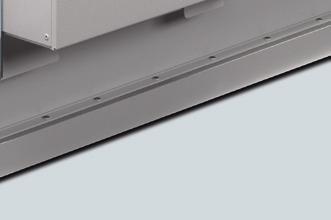
22 3.4 Attaching fixing material Figure 3-6 Using transverse stays for fixed points Never support an element at any point other than a fixing bracket. The maximum distance between horizontal fixing brackets will depend on their design (load capacity, etc.); in theory, 2 m is considered a suitable distance. Greater distance between fixing brackets only on request. Trunking weights and bracket distances Type LX, A01 A02 A04 A05 A06 A07 A08 A09 A10 Horizontal, on edge m Horizontal, flat m Weight kg Type LX, C01 C02 C03 C04 C05 C06 C07 C08 C09 Horizontal, on edge m Horizontal, flat m Weight kg Installation Manual, 06/2011, A5E
23 3.4 Attaching fixing material In designing supports, consider the following: The maximum capacity of fixing brackets in terms of supporting at least the weight of the busbar trunking system plus 90 kg, in accordance with IEC/EN Fixing points on the structure and suitable accessories (plugs, etc.) Feasibility of fixed points (should be given particular consideration as regards horizontal run layouts) Please take the particular requirements of vertical trunking, i.e. manoeuvrability, suspension of elements, execution, etc. into consideration. Wall bracket The same maximum permissible values apply to wall brackets as to ceiling brackets. You must also insert additional transverse stays when implementing fixed points. A wall bracket consists of a wall beam and a set of clamping brackets (type LX-K from LX range). The customer must provide the wall beams. Figure 3-7 Wall bracket for LX element mounted flat Installation Manual, 06/2011, A5E
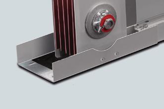
24 3.4 Attaching fixing material Spring brackets for vertical installation on walls Mounting the bracket for vertical installation Figure 3-8 Mounting the bracket for vertical installation on the wall Figure 3-9 Mounting the bracket for vertical installation on the wall CAUTION When delivered, fixing brackets are adjusted to the weight to be supported using the red screws. Do not remove these screws until installation has been completed. Follow the installation steps described here to the letter. 1. Mark the anchorage holes on the wall, using fixing bracket "A" (1) as a template if you so wish. 2. Drill the holes and insert the plugs into them. Note The fixing bracket should be attached to the wall using plugs appropriate to the weight to be supported and the fixing material used. 22 Installation Manual, 06/2011, A5E
25 3.4 Attaching fixing material 3. Attach the bracket for vertical installation using screws "B" (4). 4. Remove fixing studs "C" (2), held by nuts "D" (2), which fix the busbar trunking system. 5. Install all fixing brackets in the corresponding locations before installing the busbar trunking run. Mounting the busbar trunking system on a bracket for vertical installation Figure 3-10 Mounting the busbar trunking system on a bracket for vertical installation 1. Position busbar trunking system element "E" (1) at the desired installation location using slings or other lifting lugs. Observe the installation instructions. 2. Ensure that the element is correctly positioned in terms of the adjoining element. 3. Establish an electrical and mechanical connection between adjoining elements, taking note of the relevant instructions. 4. Screw fixing studs "C" (2) onto the fixing bracket in order to fasten the element. Place them against the wing of the element as shown in the diagram. Also use nuts and washers "D" (2). 5. Remove the slings or lifting lug used. The element is now supported solely by the fixing bracket. 6. Once installation of the entire vertical busbar run is complete, slacken and fully remove the red upper adjustment screws "F" (2) to activate the fixing bracket. 7. Keep the red adjustment screws "F" for any extensions that may need to be added later on. Installation Manual, 06/2011, A5E
26 3.4 Attaching fixing material Floor fixing for spring brackets Figure 3-11 Mounting the bracket for vertical installation on the floor Figure 3-12 Mounting the bracket for vertical installation on the floor 24 Installation Manual, 06/2011, A5E
27 3.4 Attaching fixing material 1. Use screws "A" (4) to attach the additional vertical flange to a module. Figure 3-13 Mounting the bracket for vertical installation on the floor 2. Use screws "B" (4) to attach the module to the floor via the additional flange. 3. Please refer to the description in Spring brackets for vertical installation on walls (Page 22) for details on how to attach the busbar trunking system elements. Installation Manual, 06/2011, A5E
28 3.4 Attaching fixing material Fixing brackets with fixed point for vertical installation Figure 3-14 Fixing brackets with fixed point for vertical installation Figure 3-15 Mounting fixing brackets with fixed point for vertical installation 26 Installation Manual, 06/2011, A5E
29 3.5 Connecting units 1. Mark the anchorage holes on the wall, using fixing bracket "A" (1) as a template if you so wish. 2. Use screws "B" (4) to attach the fixing brackets with fixed points to the wall. Figure 3-16 Mounting fixing brackets with fixed point for vertical installation 3. Mark the anchorage holes on the heat sink wings of the busbar enclosure, using the fixed point drill holes as a template. NOTICE Ensure that all joint block connections are completely covered before you start to drill. No metal chips should be allowed to fall into the joint blocks, as these would adversely affect the electrical connection. 4. Drill the holes and extract all resulting metal chips during the drilling process. 5. Use screws "C" to attach the fixing bracket with fixed point to the busbar enclosure. 3.5 Connecting units NOTICE Ensure that all contact surfaces are clean and free of impurities. Installation Manual, 06/2011, A5E
30 3.5 Connecting units The joint block offers two different joining options, depending on the requirements of the installation and the installation engineer: 1. Joining option where the busbar trunking system elements are assembled by joining the ends together (recommended option). 2. Joining option where the busbar trunking system elements are assembled from above Joining elements by joining the ends together 1. Remove the upper junction cover "A" (1) and the transportation lock by removing screws "B" (4). 2. Turn the junction nut "C" (1) anti-clockwise to open the junction fully. 40 FE Figure 3-17 Dismantling the joint block's flange cover 3. Line up the elements to be joined to one another, ensuring that the joint block does not become tilted. 28 Installation Manual, 06/2011, A5E

31 3.5 Connecting units 4. Move the element "D" (1) so that the ends are inserted into the joint block of the fixed element "E" (1). Check the position of the elements to be connected. If necessary, realign the elements so that they sit flush and do not get bent in the joint block. Figure 3-18 Connecting busbar trunking system elements with elements on their edge When flat, the entire busbar run is rotated Move the elements towards each other to such an extent that the distance between them is exactly 230 mm and the pin fits into the control opening of the flange cover (see following figure).! Figure 3-19 Connecting busbar trunking system elements with elements on their edge When flat, the entire busbar run is rotated 90. Installation Manual, 06/2011, A5E
32 3.5 Connecting units 6. Gradually and carefully, turn the nut "C" (1) clockwise without stopping until the external nut breaks off, giving a tightening torque of between 110 Nm and 120 Nm. crack 2 x 13 (20 Nm) 40 FE 24 (120 Nm) Figure 3-20 Checking the position of the joint block 30 Installation Manual, 06/2011, A5E
33 3.5 Connecting units 7. Check the distance between the elements again and ensure that it is 230 mm. Check again to ensure that the top pin fits into the top flange cover. 8. After checking the clamping position, attach the flange cover "A" using the screws "B" (4). The joint block assembly is then complete. Figure 3-21 Attaching the flange cover CAUTION There is a second internal nut "M" under the retaining ring for future use. The external nut has been designed to break off at the pressure required to achieve electrical and mechanical contact. When the external nut breaks off, the red safety ring drops down. This shows that the joint has been tightened (no further checking is necessary). See also Handling (Page 11) Connection from above It may sometimes be necessary to insert and join the elements from above or below. This is usually the case if the length fits snugly or if not much space is available. To do so, carefully guide the open end into the joint block (as shown in the example) from above or below. Installation Manual, 06/2011, A5E
34 3.5 Connecting units Figure 3-22 Connection from above NOTICE Ensure that the joint block is correctly centred between the two elements to be joined. Plan the installation of the connections in advance to avoid subsequent problems. Never knock or hit the joint block when inserting it between the two elements. Instead, insert it carefully, otherwise the elements may get damaged. You can find details on the further assembly steps for joining the busbar trunking system elements under Joining elements by joining the ends together (Page 28). The other steps and notes apply and must be observed. 32 Installation Manual, 06/2011, A5E
35 3.6 Expansion unit 3.6 Expansion unit Mounting the expansion unit Prior to mounting, ensure that the expansion element is blocked by the fixing bracket "C" shown (delivery condition). 40 FE Figure 3-23 Expansion unit Fit the expansion unit in the same way as any other busbar trunking system element in the position indicated in the installation drawings, following the assembly instructions given in Connecting units (Page 27). Place the expansion unit on two beams. Installation Manual, 06/2011, A5E
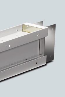
36 3.7 Flanged end Without releasing the expansion unit, install the following busbar trunking system element and attach it to the corresponding flanges. Releasing: Remove screws "A" (4) from the expansion element to enable it to move freely. CAUTION Never install fixing brackets in the expansion area "B". Do not attach expansion elements to the fixing bracket, as this will result in the temperature-dependent expansion of the run not being fully compensated. Attach one fixing bracket in front of the expansion area and one behind to ensure that the element works correctly. Two support points are provided for each expansion unit. Do not remove screws "A" (4) without having first installed the two elements adjoining the expansion unit in their final positions. 3.7 Flanged end Flanged end The flanged end connects the busbar trunking system to external power supplies or outputs, both mechanically and electrically. These external power supplies are usually distribution boards for low-voltage main distribution systems. Once the equipment has been received from the factory, the procedure below must be strictly adhered to prior to installation: 1. Storage in accordance with Storage prior to installation (Page 34). 2. Transport and handling leading up to installation in the distribution board in accordance with Transport and handling at the installation location (Page 35). 3. Installation in accordance with Installation (Page 37) Storage prior to installation Take note of the following when storing the flanged end: Store the flanged end in its original packaging and use site transportation equipment (pallet, fixing devices). Do not subject the flanged end to any additional mechanical loads. 34 Installation Manual, 06/2011, A5E
37 3.7 Flanged end Transport and handling at the installation location Only use appropriate transportation equipment to transport the transformer connection unit. Do not remove any protective transportation devices until transport has been completed. Attach lifting aids such as fabric ropes and belts (B) to the whole of the flanged end, i.e. around the flange plate and parallel to the connection busbars of phases L1, L2, L3 and N(PEN). Ensure that the mechanical stress on the enclosure and on the busbars is equally distributed. The LX...FA flanged end must be in a vertical position whilst it is being lifted (see illustration). Figure 3-24 Transporting the flanged end Figure 3-25 Transporting the flanged end The LX...FA flanged end must be placed on two wooden blocks (A) on top of the distribution board in the position specified (see illustration). Then remove the ropes and the wooden blocks to install the LX...FA in the distribution board after setting it down. Installation Manual, 06/2011, A5E
38 3.7 Flanged end A B C Wooden block Rope Cover plate Figure 3-26 Correct transport position Figure 3-27 Impermissible transport position (no wooden blocks, rope attached incorrectly) 36 Installation Manual, 06/2011, A5E
39 3.7 Flanged end Installation Preparing the non-siemens distribution board for the connection of the flanged end 1. Align the distribution board mounting surface so that it is flat. 2. Make the cut-outs in accordance with document No. A5E Reinforce the distribution board mounting surface in accordance with the weight of the flanged end. 4. The distribution board must contain fixtures for mechanically securing the flanged end. The flanged end's own weight must be mechanically decoupled from the electrical connection (copper connection). 5. Electrical connecting lugs must be provided for the electrical connection. During this process, observe the flanged end connection dimensions and cross-section specifications, as well as the distribution board manufacturer's specifications. Installing the flanged end in the distribution board Following storage and transport to the installation location, you must first mechanically secure the flanged end in the distribution board. After that, you electrically connect the flanged end to the busbars or the circuit breaker. Securing the flanged end mechanically 1. The power cables of the LX...FA must be mechanically fixed in the distribution board. The LX...FA busbars must not be subjected to any additional forces. 2. Attach cover plate "C" to the distribution board enclosure. Observe the distribution board specifications relating to the degree of protection. It may be necessary to use additional sealant in order to achieve degrees of protection higher than IP 55. Installation Manual, 06/2011, A5E
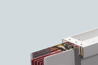
40 3.7 Flanged end Connecting the flanged end electrically 1. Remove the protective transportation devices. 2. Perform the electrical connection in accordance with the flanged end specifications (minimum cross-sections in accordance with the installation instructions) and the information provided by the distribution board manufacturer. Dimension the connecting material in accordance with these specifications. 3. Take note of the following when connecting conductor lugs with flanged ends: Drill holes are provided for connection in the case of single systems. No drill holes are provided in the parallel connectors of double systems; you must make these holes yourself during installation. Figure 3-28 Flanged end, single system with drill holes for connection Figure 3-29 Flanged end, double system without drill holes in the parallel connector "D" 38 Installation Manual, 06/2011, A5E
41 3.7 Flanged end Note You must comply with the required minimum cross-sections for the flanged end, otherwise the maximum permissible limit temperature of 130 C cannot be guaranteed. The design of the electrical connection determines the short circuit strength. The designer, usually the distribution board manufacturer or constructor, is responsible for the temperature and short circuit strength of the electrical connection. NOTICE Depending on the system, the flanged ends weigh between 13.4 kg and 89.6 kg Handling if multiple busbar runs are laid in parallel Procedure With busbar runs connected and laid in parallel, consisting of individual systems, the electrical conductors are connected in parallel to the terminal boxes for flanged ends and transformers. The parallel connection is carried out using additional parallel connectors that in the case of parallel connected single systems must, like all other connecting material, be provided by the customer. Installation is performed as described in Installation (Page 37). CAUTION You must follow the assembly sequence step by step in order to install multiple flanged ends connected in parallel. The first step deals with the mechanical and the second with the electrical connection. Installation Manual, 06/2011, A5E
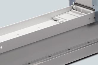
42 3.8 Transformer connection Figure 3-30 Using parallel connector "A" on the flanged end 3.8 Transformer connection Transformer connection unit The transformer connection unit connects the busbar trunking system to external transformers, both mechanically and electrically. The mechanical connection is only possible with encapsulated transformers on the transformer enclosure via the adapter flange LX-FLP. However, you can also connect the transformer connection unit to other external power supplies, such as distribution boards for low-voltage main distribution systems or generators Storage prior to installation Take note of the following when storing the transformer connection unit: Store the transformer connection unit in its original packaging and use site transportation equipment (pallet, fixing devices). Do not subject the transformer connection unit to any additional mechanical loads. 40 Installation Manual, 06/2011, A5E
43 3.8 Transformer connection Transport on-site Only use appropriate transportation equipment to transport the transformer connection unit. Attach lifting aids such as fabric ropes and belts to the whole of the transformer connection unit. Use fabric slings to suspend the busbar trunking system elements. Attach the slings as shown in the illustration. The elements are supplied with special parts for securing the slings in place and for supporting their own weight. Figure 3-31 Transformer connection units CAUTION Never use abrasive or metal slings under any circumstances. Never suspend the elements by their conductors, as this could potentially damage them beyond repair. Installation Manual, 06/2011, A5E
44 3.8 Transformer connection Positioning the transformer connection unit above the transformer Always position the connection lugs of the transformer connection unit over the centre of the transformer connection lugs; you may have to move the transformer to achieve this. Ensure that no more than 200 mm separate the connection lugs of the transformer connection unit and those of the transformer. Only use appropriate flexible connecting devices (such as flexible copper strips provided by the customer) to establish the electrical connection. Figure 3-32 Positioning the transformer connection unit Attaching the transformer connection unit at the installation location The element can be suspended in the following ways: Via the LX clamping brackets on the on-site fixing struts provided by the customer Via the transport bolt eyes on the side of the element Figure 3-33 Attaching the transformer connection unit 42 Installation Manual, 06/2011, A5E
45 3.8 Transformer connection Handling if multiple busbar runs are laid in parallel Procedure If busbar runs are laid in parallel, you must connect multiple transformer connection units in parallel too. 1. Mechanical connection: When attaching the units above the transformer, the large amount of space required means that you must take particular note of the installation dimensions of the transformer connection units and the transformer. 2. Electrical connection: The parallel connection is carried out using additional parallel connectors that must be provided by the customer. Refer to the supplied installation instructions for minimum specifications relating to the connecting surface and cross-section of the parallel connectors. An installation engineer must inspect the external electrical and mechanical connections. Note It is beyond the scope of this manual to document the huge number of different on-site conditions that may arise. Therefore, we recommend that installation experts evaluate onsite conditions. CAUTION You must follow the assembly sequence step by step in order to install multiple transformer connection units connected in parallel. The first step deals with the mechanical and the second with the electrical connection. Figure 3-34 Example: Parallel connection only Installation Manual, 06/2011, A5E
46 3.9 Fire barrier A B Transformer connection unit Parallel connector Figure 3-35 Example: Parallel connection plus connection to transformer 3.9 Fire barrier Fire barrier regulations If the busbar run passes through a fire wall or ceiling, you must provide the run with a fire barrier. For individual systems, the fire barrier can be fitted around the busbar element in the factory prior to delivery. Alternatively, the busbar element and the fire barrier can also be supplied separately in an MOS version. It is then fitted to the busbar element on site. For double systems, the fire barrier can only be fitted to the busbar element in the factory. The MOS version is not available. It is not permissible to mount the fire barrier via the junction (joint block). Note Depending on country-specific regulations, it may be necessary to attach additional fire barrier notices directly at the installation site. Fire barrier signs required directly at the installation site. 44 Installation Manual, 06/2011, A5E
47 3.9 Fire barrier The following conditions must be met in order for fire barrier to be installed (see illustration): Permissible fire barrier Permissible fire barrier Permissible fire barrier Installation of MOS fire barrier Check the kit to ensure nothing is missing. Components for the inner fire barrier channel: 4 Promat plates 4 mineral mats 16 fixing screws Components for the outer fire barrier channel: 4 Promat outer plates 2 Promat front plates 32 fixing screws Other components: 1 tube Promat filler 4 Promat sealing blocks 2 Promat fixing brackets for vertical assembly Installation Manual, 06/2011, A5E
48 3.9 Fire barrier 1. Install the first fire barrier cladding in 5 steps as shown below. 2. Once the LX system has been installed in the fire wall, use mineral mortar to fill the gap x 2 2x 3 2x 650 x (140/165/210/290) 4 2x 650 x x Figure 3-36 MOS fire barrier 46 Installation Manual, 06/2011, A5E
49 3.9 Fire barrier 3. Install the second fire barrier cladding in steps 6 to 10 as shown below x 650 x (190/215/260/340) 7 2x 650 x x 9 4x 50.5 x (242/266/312/392) 10 40x Figure 3-37 MOS fire barrier Installation Manual, 06/2011, A5E
50 3.9 Fire barrier 4. Insert the filler (step 11) and the components (12) in the openings in the profile Filler Figure 3-38 MOS fire barrier Components Figure 3-39 MOS fire barrier 48 Installation Manual, 06/2011, A5E
51 3.9 Fire barrier Particular aspects of installation in a wall in compliance with the building authority approval Z The building authority approval Z is valid for the German market. Wall barrier Figure 3-40 Max. permissible LX system fixing distances for wall installation Installation Manual, 06/2011, A5E
52 3.9 Fire barrier Ceiling barrier Figure 3-41 Max. permissible LX system fixing distances for centre ceiling installation 50 Installation Manual, 06/2011, A5E
53 3.9 Fire barrier Figure 3-42 Max. permissible LX system fixing distances for ceiling surface installation Installation Manual, 06/2011, A5E
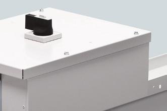
54 3.10 Tap-off unit 3.10 Tap-off unit Tap-off units from 50 A to 630 A 1. These tap-off units are positioned at the tap-off points on the trunking. Power is tapped via the tap-off point. 2. See the relevant instructions for more details and instructions on mounting tap-off units. Note You must check the necessary space requirements prior to mounting. These tap-off units cannot be positioned at junctions above a joint block. The necessary space requirements must be taken into account during the project design stage. Figure 3-43 Space requirements for tap-off units Tap-off units from 800 A to 1,250 A 1. These tap-off units are permanently mounted (bolted on) above the trunking's junction joint block. 2. This joint block must be replaced by a special tap-off joint block in order to enable power to be tapped. 52 Installation Manual, 06/2011, A5E
55 3.10 Tap-off unit 3. Switch the voltage off and safeguard the run against restart in accordance with on-site regulations. 4. See the relevant installation instructions for more details and instructions on mounting tap-off units. Note You must check the necessary space requirements prior to mounting. Tap-off units can only be mounted via straight trunking units with a minimum distance of 2000 mm from the centre of one joint block to the next. The necessary space requirements must be taken into account during the project design stage. Figure 3-44 Plug-in compatibility of the tap-off units Installation Manual, 06/2011, A5E
56 3.10 Tap-off unit Lateral mounting of tap-off units above 400 A in runs for horizontal installation If the tap-off units are mounted laterally, the mechanical load caused by the weight of the units and the cables to be connected mean that we strongly recommend you use additional supports (beams or brackets). A B C D Additional beam for tap-off unit Tap-off unit Busbar run Beam for busbar run Figure 3-45 Laterally mounted tap-off units should have additional mechanical support Additional beams in line with A und D are not available as LX attachment accessories and must be procured externally. Note It is beyond the scope of this manual to document the huge number of different on-site conditions that may arise. Therefore, we recommend that installation experts evaluate onsite conditions. 54 Installation Manual, 06/2011, A5E
57 Commissioning Commissioning Steps to be performed prior to electrification of the line Steps to be performed prior to electrification of the line WARNING Hazardous voltage! Danger of death or serious injury! Therefore, proceed with extreme caution and follow these instructions carefully. 1. Check that all connections are fully tightened. Follow the instructions relating to tightening torques (visual inspection with record of results). 2. Check all suspension and fixing elements. All the fixing studs and screws of the fixing brackets must be tightened. 3. Make sure that all tap-off units and tapping equipment is disconnected (OFF). 4. Insulate the busbar trunking system from the connections to transformers, switches, meters, etc. 5. Carry out an insulation resistance test to make sure that there are no short circuits or earth failures in the system (phase - earth, phase - neutral and phase - phase). You will observe that the readings vary depending on the length of the run, the number and size of the conductors and the level of moisture in the atmosphere. Record the measured values in an insulation test report. If you obtain readings lower than 1 MΩ per 100 m (1 MΩ x 100/length of run in metres), please contact technical support. As a rule, you must comply with the relevant countryspecific regulations (in Germany, this is a minimum of 0.5 MΩ). 6. Check that the poles on the busbar trunking system and those on the transformers, switches, meters, etc. correspond correctly on electrification. Installation Manual, 06/2011, A5E
58 Commissioning 4.2 Electrifying the line 4.2 Electrifying the line Electrifying the line WARNING Hazardous voltage! Danger of death or serious injury! The first time that the busbar trunking system conductors are electrified can be dangerous. Therefore, you must follow the instructions below to the letter, along with the country-specific regulations valid in each case. 1. Qualified personnel must be present the first time the line is electrified. If short circuits or earth failures caused by incorrect installation have not been previously detected, this can lead to serious consequences once voltage is applied. 2. There must be no electrical load connected to the busbar trunking system when it is electrified; the entire system must be checked to ensure that this is the case. 3. You must electrify the line step by step, starting at the power supply and moving towards the loads at the end. The principal elements must be electrified first, followed by the feed equipment and, finally, the secondary element circuits. You must act with purpose and conviction when connecting the line. 4. Once the line has been connected, consumers such as lights, contactors, heaters and motors can be switched on. 5. In normal operation the busbar trunking system will produce a slight buzzing sound. Excessive noise may indicate that components have not been properly secured or metal parts have been incorrectly assembled. 6. Faults caused by short circuits must trigger the protective device for the feeder unit in the manner prescribed by the official regulations. You must ensure that the system is deenergised before you eliminate the cause of the fault. Observe the five safety rules: 1. Disconnect; 2. Safeguard against restart; 3. Ensure the system is de-energised; 4. Earth and short circuit; 5. Cover and safeguard neighbouring live parts. 56 Installation Manual, 06/2011, A5E
59 Service and maintenance 5 The LX busbar trunking system is maintenance-free as long as the following conditions are met: Assembly was performed in line with the valid guidelines as per the installation instructions and the installation manual. Commissioning was performed correctly and then checked and logged with insulation measurements and visual inspections. There are no extreme mechanical loads due to external forces or significant impairment due to foreign bodies or dust. There are no extreme stresses/loads due to water or liquids. There are no extreme stresses/loads due to aggressive media. There are no other malfunction-based loads/stresses due to short circuits, fire or gas. This maintenance-free claim does not include devices fitted in tap-off units, feeder units or coupling units. The instructions on their maintenance should be taken from the respective manuals/documentation supplied with the devices. If any of the conditions listed above cannot be guaranteed, you should consult your SIEMENS contact directly. Please also get in touch with your SIEMENS contact for any additional inspections that have to be performed regularly for the erector and operator due to country-specific standards, regulations on accident prevention and safety, as well as for special work areas. Expansions As a flexible power distribution board, the LX busbar trunking system can in principle adapt to meet local needs in terms of loads and can also be expanded for new loads. As a first stage it can be sufficient simply to plug existing or new tap-off units into existing, unused tap-off points. If there are no more tap-off points available or if certain buildings/areas are not supplied by the LX, it is necessary in a second stage to extend the LX run with appropriate trunking units. This involves removing the busbar trunking system element from the LX run. Installation Manual, 06/2011, A5E
60 Service and maintenance 5.1 Dismantling a busbar trunking system element in a horizontal line Dismantling busbar trunking system elements It may sometimes be necessary to dismantle a length of the busbar trunking system for the purposes of expansion or replacement. These instructions indicate the correct procedure to follow in such a case. WARNING Before disconnecting, take the switching capacity of the busbar trunking system protector element into consideration. All power must be disconnected before you disconnect the busbar trunking system. The header protection systems must be disconnected in order to insulate the busbar trunking system. WARNING Remember to completely disconnect the line before handling. Observe the five safety rules: 1. Disconnect 2. Safeguard against restart 3. Ensure the system is de-energised 4. Earth and short circuit 5. Cover and safeguard neighbouring live parts NOTICE Only qualified personnel with electrotechnical knowledge may perform the operations indicated in this section. 5.1 Dismantling a busbar trunking system element in a horizontal line 1. Disconnect all power to the busbar trunking system. 2. Disconnect the busbar trunking system from the supply. 3. Fully insulate the busbar trunking system and safeguard it against restart. 4. Completely release the joint blocks of the relevant elements (see the section titled "Dismantling junctions" in this chapter). The first element must be removed in a transversal direction. All other elements can be removed in a longitudinal or transversal direction. The busbar trunking system must be handled in accordance with the installation instructions (see installation instructions). 58 Installation Manual, 06/2011, A5E
61 Service and maintenance 5.2 Dismantling a busbar trunking system element in a vertical line 5.2 Dismantling a busbar trunking system element in a vertical line 1. Disconnect the line in accordance with the aforementioned instructions, "Dismantling a busbar trunking system element". 2. Let the busbar trunking system cool until the expansion disappears and the run reassumes its initial length (this takes 12 hours at the most). 3. Fix the entire vertical line in place by blocking the springs of all brackets for vertical installation on the respective line 4. by (manually) threading the red nuts F (2) onto the spigot until they make contact with the profile of support G. Do not tighten the nuts. Figure 5-1 Brackets for vertical installation NOTICE Lock the brackets for vertical installation before removing the weight of the busbar trunking system, otherwise the brackets will have to be readjusted. 5. Completely release the joint blocks of the element to be dismantled. 6. Release and remove the retaining clamps from the fixing bracket. 7. Remove the element (see operating manual). Installation Manual, 06/2011, A5E
62 Service and maintenance 5.3 Dismantling joint blocks 8. The first element must be removed in a transversal direction. All other elements can be removed in a longitudinal or transversal direction. 9. The busbar trunking system must be handled in accordance with the installation instructions (see installation instructions). 5.3 Dismantling joint blocks 1. Completely disconnect the busbar trunking system from the mains before dismantling a junction in order to avoid accidents. Disconnect the busbar trunking system by following the instructions found in the section titled "Dismantling a length of the busbar trunking system" in this chapter. 2. Slacken the 4 screws "A" of the upper cover "B" of the joint block and remove the cover "B". 3. Slacken and remove the connection nut "C" using a suitable tool "D". 4. Slacken the 4 screws "E" of the lower cover "F" of the joint block and remove the cover "F". CAUTION Make sure that the joint block does not slide out! 5. Slacken and remove the joining screw (C). The junction has now been released and the joint block can be removed. Figure 5-2 Removing joint blocks - Step 1 60 Installation Manual, 06/2011, A5E

63 Service and maintenance 5.3 Dismantling joint blocks Figure 5-3 Removing joint blocks - Step 2 Figure 5-4 Removing joint blocks - Step 3 Installation Manual, 06/2011, A5E
Electrical Power Distribution Low-Voltage Systems SIVACON 8PS busbar trunking systems Installing with LI system
 Introduction 1 Application planning 2 Electrical Power Distribution Low-Voltage Systems SIVACON 8PS busbar trunking systems Installation Manual Installation 3 Commissioning 4 Service and maintenance 5
Low-Voltage Power Distribution and Electrical Installation Technology
 Busbar trunking system Installation Manual 02/2011 Low-Voltage Power Distribution and Electrical Installation Technology Answers for infrastructure. SIVACON 8PS - Installation with BD2 system Low-voltage
SIMATIC Ident RFID systems ANT 3 Compact Operating Instructions
 SIMATIC Ident RFID systems Compact Operating Instructions Legal information Warning notice system This manual contains notices you have to observe in order to ensure your personal safety, as well as to
SINAMICS drives SINAMICS DCM. DC converters from 6 kw to 2500 kw for variable-speed direct-current drives
 SINAMICS DCM DC converters from 6 kw to 2500 kw for variable-speed direct-current drives Application: Continuous operation in the case of a pulse encoder error Edition 01-12/2010 SINAMICS drives SINAMICS
Pow-R-Feed Systems Service Manual
 Pow-R-Feed Systems Service Manual Important Safety Instructions Please read this manual carefully and follow its instructions. Improper use or failure to follow these instructions could result in serious
Digital electronic module 4DO DC24V/2A HF (6ES7132-4BD30-0AB0) SIMATIC
 SIMATIC") Digital electronic module 4DO DC24V/2A HF (6ES7132-4BD30-0AB0) SIMATIC Properties 1 Parameters 2 Diagnostics 3 ET 200S distributed I/O Digital electronic module 4DO DC24V/2A HF (6ES7132-4BD30-0AB0) Manual
Digital electronic module 4DO DC24V/2A HF (6ES7132-4BD30-0AB0) SIMATIC Properties 1 Parameters 2 Diagnostics 3 ET 200S distributed I/O Digital electronic module 4DO DC24V/2A HF (6ES7132-4BD30-0AB0) Manual
SIMATIC Ident. RFID systems SIMATIC RF615A. Characteristics 1. Ordering data. Installing and mounting. Connecting the antenna 4
 Characteristics 1 Ordering data 2 SIMATIC Ident RFID systems Operating Instructions Installing and mounting 3 Connecting the antenna 4 Antenna parameter assignment 5 Antenna patterns 6 Maximum read/write
Taurean Sectional Garage Door INSTALLATION INSTRUCTIONS
 BEFORE YOU BEGIN MAKE SURE THESE INSTRUCTIONS ARE READ AND UNDERSTOOD COMPLETELY. THESE INSTRUCTIONS ARE INTENDED FOR PROFESSIONAL GARAGE DOOR INSTALLERS. ALL REFERENCES ARE TAKEN FROM THE INSIDE LOOKING
INSTALLATION MANUAL PBL-UMP
 INSTALLATION MANUAL PBL-UMP Table of Contents Warning Statements... 4 Parts List... 5 Installation Tools... 5 Features... 7 Projector Preparation... 8 Bracket Installation... 10 Leveling the Mounting Bracket...
SINAMICS drives. SINAMICS DCM as a DC voltage source. Application. Answers for industry. Edition 01/2014
 SINAMICS drives SINAMICS DCM as a DC voltage source Application Edition 01/2014 Answers for industry. Compact User Manual Legal information Warning notice system This manual contains notices you have to
southpaw enterprises, inc.
 southpaw enterprises, inc. Store these instructions with the enclosed maintenance checklist in a safe place. You may also access them on our website. Instruction Sheet Wood Joist 2-1/2 Ft. Drop Ceiling
Central Inverter SUNNY CENTRAL 200 / 250 / 250HE / 350
 Central Inverter SUNNY CENTRAL 200 / 250 / 250HE / 350 Installation Guide SC20_25_35-IEN094521 98-4004821 Version 2.1 EN SMA Solar Technology AG Table of Contents Table of Contents 1 Notes on this Manual..............................
Tube Facing Tool.
 www.swagelok.com Tube Facing Tool This manual contains important information for the safe and effective operation of the Swagelok TF72 series tube facing tool. Users should read and understand its contents
Universal flat-panel mount
 I N S T A L L A T I O N M A N U A L Universal flat-panel mount www.christiedigital.com PM 2004/ REV 02 Contents - Assembly drawing - Fine tune tilt adjustments - Parts list - Installing the adapter plate
Pole Mount Installation Guide
 Pole Mount Installation Guide (No Fine Adjustment) 495R Billerica Ave. North Billerica, MA 01862 USA Tel (978)459-8800 fax (978)459-3310 / 8814 Email: sales@radiowaves.com www.radiowaves.com IMPORTANT!
SAFETY THIS PRODUCT IS FOR OFFROAD USE ONLY. ALL LIABILITY FOR INSTALLATION AND USE RESTS WITH THE OWNER.
 SAFETY Your safety and the safety of others is very important. In order to help you make informed decisions about safety, we have provided installation instructions and other information. These instructions
Curium 19.4H Installation Instructions & Parts List
 Curium 19.4H Installation Instructions & Parts List Illustration Curium 19.4H Right Hand Page 1 of 21 30/06/2016 Revision 1.0 IMPORTANT This shower screen / enclosure must be installed by suitably qualified
INSTALLATION INSTRUCTIONS LARGE FLAT PANEL IN WALL ENCLOSURE Model: PAC-500
 INSTALLATION INSTRUCTIONS LARGE FLAT PANEL IN WALL ENCLOSURE Model: PAC-500 Specifications: Designed for in-wall installation spanning a minimum of 3 wood studs, 16" on center. Accomodates MWR, PWR and
SINVERT. Technical requirements for medium-voltage transformers for use with SINVERT central inverters. Application manual 04/2012
 Technical requirements for medium-voltage transformers for use with SINVERT central inverters Application manual 04/2012 SINVERT Answers for the environment. Technical requirements for medium- Technical
Installation Instructions
 READ BEFORE INSTALLING UNIT For Slider Casement Air Conditioners To avoid risk of personal injury, property damage, or product damage due to the weight of this device and sharp edges that may be exposed:
Magnetic Inductive Flow Sensor induq
 Operating manual (Translation) Operating manual... page 1-16 Magnetic Inductive Flow Sensor induq Series VMZ SIKA Ba_VMZ_en 10/2014. Please keep this operating manual for future reference. If the device
Power Train Lift Max. Capacity: 1,250 lbs.
 655 EISENHOWER DRIVE OWATONNA, MN 55060 USA PHONE: (507) 455-7000 TECH. SERV.: (800) 533-6127 FAX: (800) 955-8329 ORDER ENTRY: (800) 533-6127 FAX: (800) 283-8665 INTERNATIONAL SALES: (507) 455-7223 FAX:
Sliding Door Kit
 YOU MUST READ THIS DOCUMENT BEFORE YOU BEGIN TO ASSEMBLE THE DOOR KIT. Thank you for purchasing this GrowSpan door kit. When properly assembled and maintained, this product will provide years of reliable
ROBOT KR 350. Installation, Connection, Exchange. Ro/Me/03/ en. 1of 26
 ROBOT KR 350 Installation, Connection, Exchange 1of 26 e Copyright KUKA Roboter GmbH This documentation or excerpts therefrom may not be reproduced or disclosed to third parties without the express permission
Impact Wrench MODEL 6905B MODEL 6906
 ENGLISH Impact Wrench MODEL 6905B MODEL 6906 005305 DOUBLE INSULATION I N S T R U C T I O N M A N U A L WARNING: For your personal safety, READ and UNDERSTAND before using. SAVE THESE INSTRUCTIONS FOR
Curium 19H Installation Instructions & Parts List
 Curium 19H Installation Instructions & Parts List Illustration Curium 19H Right Hand Page 1 of 15 01/07/2016 Revision 2.1 IMPORTANT This shower screen / enclosure must be installed by suitably qualified
MPA-9000 Universal Ceiling Projector Mount Kit
 I N S T R U C T I O N M A N U A L Universal Ceiling Projector Mount Kit The Universal Ceiling Projector Mount provides a unique, simplified method of ceiling mounting your inverted projector. This low
Gallium 03 Installation Instructions & Parts List
 Gallium 03 Installation Instructions & Parts List Illustration Gallium 03, H1 Handle Left Hand: Open Out 04/05/2016 Revision 1.1 Page 1 of 19 IMPORTANT This shower screen / enclosure must be installed
southpaw enterprises, inc.
 southpaw enterprises, inc. Store these instructions with the enclosed maintenance checklist in a safe place. You may also access them on our website. Instruction Sheet Prefab Joist 3 Ft. Drop Ceiling Kit
INSTRUCTION MANUAL DWX723-XE HEAVY-DUTY MITER SAW STAND FINAL PAGE SIZE : 8.5IN X 5.5IN
 INSTRUCTION MANUAL DWX723-XE HEAVY-DUTY MITER SAW STAND FINAL PAGE SIZE : 8.5IN X 5.5IN DWX723-XE MITER SAW STANDS Components List A. Beam B. DW7231 Miter saw mounting brackets C. Extension arm D. DW7232
Mounting Instructions for Cisco Aironet 1550 Series Outdoor Access Point Pole-Mount Kits
 Mounting Instructions for Cisco Aironet 1550 Series Outdoor Access Point Pole-Mount Kits Date: April 2011 Part number: This document describes how to use the Cisco Aironet 1550 Series Outdoor Access Point
MANUAL MOUNTING SYSTEM FOR BITUMEN / EPDM
 MANUAL MOUNTING SYSTEM FOR BITUMEN / EPDM EN mounting system for insulated pitched roof Bitumen / EPDM for solar panels landscape setup ESDEC BV 2015 TABLE OF CONTENT 1. Introduction 1 2. General installation
Tesla K20 GPGPU Card Installation Guide
 Dell PowerEdge C80X Tesla K0 GPGPU Card Installation Guide Regulatory Model: B06B Regulatory Type: B06B00 Notes, Cautions, and Warnings NOTE: A NOTE indicates important information that helps you make
Kiosk Solution W1000. Installation and Assembly Instructions July 2015 Edition
 Kiosk Solution W1000 Installation and Assembly Instructions July 2015 Edition All product names mentioned in this document are the trademarks, brands or registered trademarks of their respective owner.
EOS LED Surface Mounted Luminaire
 Installation Instruction Sheet INSTALLATION INSTRUCTIONS FOR JOINING AND SUSPENDING FIXTURES WARNING WARNING To reduce the risk of death, injury or property damage from fire, electric shock, cuts, abrasions,
Powersafe Termination Guide
 Powersafe Termination Guide Contents Index 1. Introduction 2. Overview 3. Termination Methods 3.1 Set screw termination 3.2. Recommended Assembly Procedure for Panel Mounted Connectors 3.3. Crimp Termination
SAFETY THIS PRODUCT IS FOR OFFROAD USE ONLY. ALL LIABILITY FOR INSTALLATION AND USE RESTS WITH THE OWNER.
 SAFETY Your safety and the safety of others is very important. In order to help you make informed decisions about safety, we have provided installation instructions and other information. These instructions
Technical description
 STAHLWILLE Standard Manoskop 721 Service Manoskop 730 List of contents Technical description... 27 ã=important safety points... 30 Operation... 32 Maintenance... 42 Cleaning the Manoskop... 47 Accessories...
PLANISHING HAMMER STAND OWNER S MANUAL
 PLANISHING HAMMER STAND OWNER S MANUAL WARNING: Read carefully and understand all INSTRUCTIONS before operating. Failure to follow the safety rules and other basic safety precautions may result in serious
Mounting instructions SZ210 Full-frame pedestal with screw-on tube with placement hinge, for type SCHATTELLO
 This height will be made to order. Mounting instructions SZ210 Full-frame pedestal with screw-on tube with placement hinge, for type SCHATTELLO The following instructions include all information necessary
Sliding Door Enclosure. Telephone Cleaning. Please retain this manual after installation for future reference and maintenance.
 Cleaning All chrome surfaces should be cleaned using a clean damp cloth. No abrasive cleaning agents or materials should be used. General glass cleaner can be used for the screen, but ensure that this
CEILING-MOUNTED MONORAIL ANCHOR TRACK SYSTEM Assembly and Operation Instruction Manual
 CEILING-MOUNTED MONORAIL ANCHOR TRACK SYSTEM Assembly and Operation Instruction Manual This manual is for various mounting types and plain and trussed track profiles. ISO 9001:2008 Registered Manual 103-0075
SIMATIC Vision Sensor SIMATIC VS130-2 and VS 130-2vcr
 s SIMATIC Vision Sensor SIMATIC VS130-2 and VS 130-2vcr Getting Started Release 09/2005 First Steps in Commissioning Safety Guidelines This manual contains notices you have to observe in order to ensure
Impact Wrench MODEL TW1000. WARNING: For your personal safety, READ and UNDERSTAND before using. SAVE THESE INSTRUCTIONS FOR FUTURE REFERENCE.
 ENGLISH Impact Wrench MODEL TW000 00605 DOUBLE INSULATION I N S T R U C T I O N M A N U A L WARNING: For your personal safety, READ and UNDERSTAND before using. SAVE THESE INSTRUCTIONS FOR FUTURE REFERENCE.
SAFETY. Injury hazard
 SAFETY Installation Guidelines Your safety and the safety of others is very important. In order to help you make informed decisions about safety, we have provided installation instructions and other information.
PRODUCT MANUAL 5-IN-1 MITER SAW STATION *SAVE THIS MANUAL FOR FUTURE REFERENCE
 PRODUCT MANUAL 5-IN-1 MITER SAW STATION *SAVE THIS MANUAL FOR FUTURE REFERENCE 92778 1 GENERAL SAFETY INFORMATION For your safety, please read these instructions carefully before use and keep them in the
General Installation Instructions
 General Installation Instructions WARNING To reduce the risk of death, injury or property damage from fire, electric shock, cuts, abrasions, falling parts and other hazards: Service of the equipment must
INSTALLATION INSTRUCTIONS Small Flat Panel Height-Adjustable, Extended Pitch Swing Arm Wall Mount Model KWE-110
 INSTALLATION INSTRUCTIONS Small Flat Panel Height-Adjustable, Extended Pitch Swing Arm Wall Mount Model KWE-110 The KWE dual swing arm wall mount is designed to provide a broad range of viewing for Small
Type XTSR71 Sizes
 (Page 1 of 13) s 494-5258 Type XTSR71 s 494-5258 Figure 1 Thomas XTSR71 Coupling 1. General Information 1.1 Thomas Couplings are designed to provide a mechanical connection between the rotating shafts
ADDUCO Hydraulic Clamping Nut
 Translation of Original Operating Manual ADDUCO Hydraulic Clamping Nut Assembly and Operating Manual Superior Clamping and Gripping Imprint Imprint Copyright: This manual remains the copyrighted property
Important Safety Instructions
 Basis Track Installation Guide Important Safety Instructions Lighting systems from Translite Sonoma are supplied as complete systems. Use only factory-supplied parts to preserve the validity of the UL
INSTALLATION INSTRUCTIONS
 INSTALLATION INSTRUCTIONS SHOWER STUDIO GLIDE Englefield has a history of making superb showers and their popularity is testament to their quality and affordability. It s the details that Englefield cares
Senior Swing. Caution
 *740132* 740132 2800 Overhead Concealed Series 9500 Surface Applied Series Senior Swing Installation Instructions Caution LCN Senior Swing The Senior Swing Power Operator System is a low energy product
SINAMICS drives SINAMICS DCM. Commutation reactors. Operating Instructions. Answers for industry. Edition 11/2013
 SINAMICS drives SINAMICS DCM Commutation reactors Operating Instructions Edition 11/2013 Answers for industry. Safety notes 1 Description 2 SINAMICS SINAMICS DCM commutating reactors Operating Instructions
Installation Guide Flat Panel Antenna Mounting Kit For
 Installation Guide Flat Panel Antenna Mounting Kit For 103670-1 495R Billerica Ave. North Billerica, MA 01862 USA Tel (978)459-8800 fax (978)459-3310 / 8814 Email: sales@radiowaves.com www.radiowaves.com
LCD DISPLAY MOUNT
 I N S T A L L A T I O N M A N U A L 38-804769-01 LCD DISPLAY MOUNT WWW.CHRISTIEDIGITAL.COM Contents - Assembly drawing - Securing the bottom wall plate - Fine tune adjustments - Marking the top plate mounting
SECTION CABLE TRAYS
 SECTION 16139 CABLE TRAYS PART 1 - GENERAL 1.1 RELATED DOCUMENTS A. Drawings and general provisions of the Contract, including General and Supplementary Conditions and Division 1 Specification Sections,
SAFETY THIS PRODUCT IS FOR OFFROAD USE ONLY. ALL LIABILITY FOR INSTALLATION AND USE RESTS WITH THE OWNER.
 SAFETY Your safety and the safety of others is very important. In order to help you make informed decisions about safety, we have provided installation instructions and other information. These instructions
Installing the Hughes BGAN Remote Antenna
 Installing the Hughes BGAN Remote Antenna Product description BGAN Remote Antenna The Hughes BGAN Remote Antenna (HNS Part No. 9501286-0001) is designed to be permanently installed with the Basic Fixed
SAFETY THIS PRODUCT IS FOR OFFROAD USE ONLY. ALL LIABILITY FOR INSTALLATION AND USE RESTS WITH THE OWNER.
 SAFETY Your safety and the safety of others is very important. In order to help you make informed decisions about safety, we have provided installation instructions and other information. These instructions
INSTALLATION INSTRUCTIONS
 INSTALLATION INSTRUCTIONS Trans4mer Grille Guard/Winch Mount Kit 645 For Chevrolet Silverado 500HD & 3500 This WARN Trans4mer system can be customized to give your Chevy Silverado a wide variety of looks,
Hedge Trimmer Attachment HA110 HA850 Complément Taille-haie HA110 HA850 Tijeras cortasetos (suplemento) HA110 HA850
 HA110 HA850") Operator s manual Manual d utalisation Manual de instrucciones Hedge Trimmer Attachment HA110 HA850 Complément Taille-haie HA110 HA850 Tijeras cortasetos (suplemento) HA110 HA850 GB FR ES KEY TO SYMBOLS
Operator s manual Manual d utalisation Manual de instrucciones Hedge Trimmer Attachment HA110 HA850 Complément Taille-haie HA110 HA850 Tijeras cortasetos (suplemento) HA110 HA850 GB FR ES KEY TO SYMBOLS
SAFETY THIS PRODUCT IS FOR OFFROAD USE ONLY. ALL LIABILITY FOR INSTALLATION AND USE RESTS WITH THE OWNER.
 SAFETY Your safety and the safety of others is very important. In order to help you make informed decisions about safety, we have provided installation instructions and other information. These instructions
Installation Instructions
 Installation Instructions READ BEFORE INSTALLING UNIT For Slider Casement Air Conditioners INSTALLATION WARNINGS AND CAUTION Carefully read the installation manual before beginning. Follow each step as
OB1U INSTALLATION INSTRUCTIONS. Interactive Flat Panel Over White Board Mount
 INSTALLATION INSTRUCTIONS Interactive Flat Panel Over White Board Mount Spanish Product Description German Product Description Portuguese Product Description Italian Product Description Dutch Product Description
Installation Instructions
 Installation Instructions Ceiling Mount Bracket for DLP Based Projectors (for High Ceilings) Model No. ET-PKD100H Contents Important Safety Notice.................. 2 For DLP Based Projector: PT-D10000
Top spin Nr /
 Top spin Nr. 1840 0000 / 1840 1000 Bedienungsanleitung 21-6680 28052014 / A Made in Germany Ideas for dental technology Top spin Nr. 1840 0000 / 1840 1000 Contents 1. Introduction...2 1.1 Symbols...2 2.
MANUAL MOUNTING SYSTEM FOR CORRUGATED ROOF
 MANUAL MOUNTING SYSTEM FOR CORRUGATED ROOF EN mounting system for corrugated roof for solar panels in portait setup (cross-system) ESDEC BV 2015 TABLE OF CONTENT 1. Introduction 1 2. General installation
THIS SHEET CONTAINS IMPORTANT SAFETY INSTRUCTIONS. SAVE THESE INSTRUCTIONS.
 LumeLEX 2026 SERIES INSTALLATION INSTRUCTIONS Important THIS SHEET CONTAINS IMPORTANT SAFETY INSTRUCTIONS. SAVE THESE INSTRUCTIONS. Warning This product must be installed in accordance with National Electrical
Single Band 125mm Profile Panel Antennas Installation and Operation Instructions Including APM-F-084-S4 & APM-T-085-S4 Mounting Kits
 General Single Band 125mm Profile Panel Antennas Installation and Operation Instructions Including APM-F-084-S4 & APM-T-085-S4 Mounting Kits This instruction sheet contains all necessary information required
INSTALLATION INSTRUCTIONS WINCH MOUNTING PLATE Part Number: Application: 2007 JEEP JK WRANGLER
 INSTALLATION INSTRUCTIONS WINCH MOUNTING PLATE Part Number: 74247 Application: 2007 JEEP JK WRANGLER Your safety, and the safety of others, is very important. To help you make informed decisions about
O W N E R ' S M A N U A L
 TABLE TENNIS TABLE MODEL NOS. T861 T861B O W N E R ' S M A N U A L 1. Read this manual carefully before starting assembly. Read each step completely before beginning each step.. Some smaller parts may
2015 RIGOL TECHNOLOGIES, INC.
 Service Guide DG000 Series Dual-channel Function/Arbitrary Waveform Generator Oct. 205 TECHNOLOGIES, INC. Guaranty and Declaration Copyright 203 TECHNOLOGIES, INC. All Rights Reserved. Trademark Information
Dual Arm Tilt LCD Mount
 Installation Manual model # 51324 M o u n t i n g S y s t e m s Dual Arm Tilt LCD Mount Fits Displays 13 to 32 Supports Up to 50 lbs (23 kgs) Projection from Wall from 3 to 17 Meets VESA Standards 50/75/100,
LIGHT FIXTURES MUST BE COMPLETELY INSTALLED PRIOR TO CEILING CONSTRUCTION
 CAUTION: BEFORE BEGINNING INSTALLATION REVIEW LAYOUT DRAWINGS, AND SHIPMENT. MAKE SURE ALL LIGHT S AND MATERIALS ARE ON SITE AND READILY ACCESSIBLE. IF ANY ICON MATERIALS ARE MISSING, CONTACT ICON INTERNATIONAL
GENERAL OPERATIONAL PRECAUTIONS PRECAUTIONS ON USING CUT-OFF MACHINE
 GENERAL OPERATIONAL PRECAUTIONS WARNING! When using electric tools, basic safety precautions should always be followed to reduce the risk of fire, electric shock and personal injury, including the following.
TOYOTA TUNDRA CARGO DIVIDER Preparation. Part Number: PT
 Preparation Part Number: PT767-34070 Kit Contents 1 1 Divider Screen 2 1 LH Bracket with Warning Label 3 1 RH Bracket without Warning Label NOTE: Part number of this accessory may not be the same as the
SAFETY THIS PRODUCT IS FOR OFFROAD USE ONLY. ALL LIABILITY FOR INSTALLATION AND USE RESTS WITH THE OWNER.
 SAFETY Your safety and the safety of others is very important. In order to help you make informed decisions about safety, we have provided installation instructions and other information. These instructions
Multiples EM_ 1.4. Install 1X1/1X2/1X3/1X4 Housings. Installation Instructions for. This product is suitable for indoor locations.
 Installation Instructions for 90EMULTI Multiples EM_. GENERAL PRODUCT I NFORMATION: This product is suitable for indoor locations. This product can be dimmed with a standard electronic dimmer or a 0-0V
Wall mounting bracket
 Install Manual Wall mounting bracket Please read this manual carefully before operating your set and retain it for future reference. OSW200 P/NO : MFL63640578 (1502-REV01) www.lg.com COMPONENT Install
OPERATOR'S MANUAL 46" SNOW BLADE. Model Numbers OEM IMPORTANT: READ SAFETY RULES AND INSTRUCTIONS CAREFULLY
 OPERATOR'S MANUAL 46" SNOW BLADE Model Numbers 190-833-OEM IMPORTANT: READ SAFETY RULES AND INSTRUCTIONS CAREFULLY MTD PRODUCTS INC. P.O. BOX 368022 CLEVELAND, OHIO 44136-9722 PRINTED IN U.S.A. FORM NO.
Assembly Instructions for model: VMPR1
 Assembly Instructions for model: VMPR1 Congratulations on your purchase! The VMPR1 ceiling mount provides a unique, simplified method of ceiling mounting inverted LCD/DLP projectors. Its low profile design
- 2 JOINER ALIGNERS - 2 JOINING BRACKETS - 4 HEX BOLTS. Factory pre-installed mud flange TOOLS REQUIRED: Phillips screwdriver, 5/16 nut driver.
 - 2 JOINER ALIGNERS - 2 JOINING BRACKETS - 4 HEX BOLTS TruGroove Drywall A3 MOUNTING Ceiling INSTALLATION System Overview These instructions review how to install drywall trim versions of TruGroove recessed
MODEL 83 Pail Handler
 MORSE MFG. CO., INC. 727 West Manlius Street P.O. Box 518 East Syracuse, NY 13057-0518 Phone: 315-437-8475 Fax: 315-437-1029 Email: service@morsemfgco.com Website: www.morsemfgco.com COPYRIGHT 2005 MORSE
YOUR LIFE. YOUR FIRE. Ortal Curved & Islands Fireplaces Installation Manual. Ortal USA - Version: 1.3 November, 2017 SKU: KPMANCIRISLUS17B
 YOUR LIFE. YOUR FIRE. Ortal Curved & Islands Fireplaces Installation Manual Ortal USA - Version: 1.3 November, 2017 SKU: KPMANCIRISLUS17B [THIS ISTALLATION MANUAL INCLUDES ASSEMBLY INSTRUCTIONS FOR THESE
Model MSPPWRTW Large Flat Panel Single Arm Wall Mount
 INSTALLATION INSTRUCTIONS Model Large Flat Panel Single Arm Wall Mount The is wall-mounted, rugged, versatile, and installer-friendly. The mount is compatible with the standard (14 x 14 ) PSB interface
INSTALLATION MANUAL PBC-UMS
 INSTALLATION MANUAL. PBC-UMS Premier Mounts 3130 E. Miraloma Avenue Anaheim, CA 92806 Phone: (800) 368-9700 Fax: (800) 832-4888 mounts@mounts.com www.mounts.com Rev. 01 PBL-110 Projector Mount Page 2 Installation
Assembly Instructions and Parts Manual JPSF-1 Fence and JPSR Rail Set #
 Assembly Instructions and Parts Manual JPSF-1 Fence and JPSR Rail Set #1002493 JET 427 New Sanford Road LaVergne, Tennessee 37086 Part No. M-708482 Ph.: 800-274-6848 Revision C3 02/2014 www.jettools.com
Muto Premium Recessed Mount. XL150/80/120 Fixed Panel ONLY - Ceiling mount. Installation instructions
 Muto Premium Recessed Mount XL150/80/120 Fixed Panel ONLY - Ceiling mount Installation instructions 936036 05-2018 EN Table of Contents Table of contents 1 Technical specifications 3 1.1 Overview 3 1.1.1
SAVE THESE INSTALLATION INSTRUCTIONS
 Light Without Boundaries LUMATO RESERVES THE RIGHT TO CHANGE PRODUCT 7500003 8/4 Light Without Boundaries LUMATO RESERVES THE RIGHT TO CHANGE PRODUCT GENERAL INSTALLATION WARNING To Reduce Risk Of Death,
Assembly Instructions
 InTandem Table System November 20 InTandem Table System - Worksurface #4 x/" 4 wood screw power beam Tools Provided T-0 Extended Torx Driver T-25 Torx Driver Additional Tools Required Soft protective
TH450A-T TH550A-T THP550-T/TS3000
 0 TH450A-T TH550A-T THP550-T/TS3000 INSTRUCTION MANUAL CEILING TYPE (OVERHEAD TRAVELING TYPE) INDUSTRIAL ROBOT SPECIFICATIONS Notice 1. Make sure that this instruction manual is delivered to the final
ETX Powered Loudspeaker Accessories
 ETX Powered Loudspeaker Accessories ETX-BRKT10, ETX-BRKT12, ETX-BRKT15, ETX-TCA-S, ETX-TCA-L, and ETX-BRKT35 en Installation Guide en 3 Table of contents 1 Safety 4 2 Installation 6 2.1 Wall mount bracket
ATBG280/6 Bench Grinder Bench Grinder ATBG280/6 230V-50Hz 280 Watt 150mm x 25mm Wheel size
 Bench Grinder ATBG280/6 230V-50Hz 280 Watt 150mm x 25mm Wheel size SPECIFICATIONS Model Number : ATBG280/6 Nominal Voltage Power Consumption No load speed Wheel size Weight 230Volt 50Hz 280 Watts 2880
LifeGear G1 /HOME GYM ITEM NO.: 63100
 LifeGear G1 /HOME GYM ITEM NO.: 63100 OWNER S MANUAL IMPORTANT: Read all instructions carefully before using this product. Retain this owner s manual for future reference. The specifications of this product
STOP. V00029AC Rev. 04 READ ALL OF THE FOLLOWING INSTRUCTIONS BEFORE REMOVING CABINET FROM SKID TOOL LIST. NET-ACCESS S-Type Network Cabinets
 Rev. 04 STOP READ ALL OF THE FOLLOWING INSTRUCTIONS BEFORE REMOVING CABINET FROM SKID NET-ACCESS S-Type Network Cabinets -Phillips screwdriver -Flatblade screwdriver -22mm socket wrench -15mm socket wrench
Installation Instructions
 Installation Instructions Ceiling Mount Bracket (for Low Ceilings) Model No. ET-PKR100S Thank you for purchasing this Panasonic product. To customers The Installation Instructions is intended for use by
INSTALLATION INSTRUCTION Solorail - Low Voltage Starter Kit
 IMPORTANT SAFETY INSTRUCTIONS: Read all instructions. Turn off power at main switch before installing or modifying the system. Do not install the system: - Within six inches of any curtain or combustible
MODEL W1.0X305A(12 ) MODEL W1.0X610A(24 ) HAND BENDING BRAKE ASSEMBLY&OPERATING INSTRUCTION
 MODEL W1.0X610A(24 ) HAND BENDING BRAKE ASSEMBLY&OPERATING INSTRUCTION") MODEL W1.0X305A(12 ) MODEL W1.0X610A(24 ) HAND BENDING BRAKE ASSEMBLY&OPERATING INSTRUCTION 1 SAVE THIS MANUAL You will need the manual for the safety warning and precautions, assembly instructions, operating
MODEL W1.0X305A(12 ) MODEL W1.0X610A(24 ) HAND BENDING BRAKE ASSEMBLY&OPERATING INSTRUCTION 1 SAVE THIS MANUAL You will need the manual for the safety warning and precautions, assembly instructions, operating
RUBBISH CHUTE TECHNICAL NOTE
 RUBBISH CHUTE TECHNICAL NOTE HAEMMERLIN - CDH GROUP 28 RUE DE STEINBOURG - BP 30045-67701 1 SAVERNE CEDEX - FRANCE Tel. + 33 (0)3 88 01 85 00 - Fax + 33 (0)3 88 01 85 39 welcome@haemmerlin.com - www.haemmerlin.com