ENGR-2300 Electronic Instrumentation Quiz 3 Spring 2015
|
|
|
- Jody Bishop
- 5 years ago
- Views:
Transcription

1 ENGR-23 Electronic Instrumentation Quiz 3 Spring 215 On all questions: SHOW ALL WORK. BEGIN WITH FORMULAS, THEN SUBSTITUTE VALUES AND UNITS. No credit will be given for answers that appear without justification. Also, if there is a small flaw in your reasoning, we will not know and not be able to give you credit for what you have correct if you do not provide information on how you solved the problem. Read the entire quiz before answering any questions. Also it may be easier to answer parts of questions out of order. 1 K. A. Connor
: Experiment is the sole source of truth. It alone can teach us something new; it alone can give us certainty.")

2 Some Additional Background 29 April Birthdays Jules Henri Poincaré (29 April July 1912) a French engineer, mathematician, theoretical physicist, and a philosopher of science who said in Science and Hypothesis (192): Experiment is the sole source of truth. It alone can teach us something new; it alone can give us certainty. It is often said that experiments should be made without preconceived ideas. That is impossible. Not only would it make every experiment fruitless, but even if we wished to do so, it could not be done. Every man has his own conception of the world, and this he cannot so easily lay aside. We must, example, use language, and our language is necessarily steeped in preconceived ideas. Only they are unconscious preconceived ideas, which are a thousand times the most dangerous of all. Marietta Blau During the 192s and 193s, Viennese physicist Marietta Blau (29 April January 197) pioneered the use of photographic methods for imaging high-energy nuclear particles and events. In 1937 she and Hertha Wambacher discovered disintegration stars the tracks of massive nuclear disintegrations in emulsions exposed to cosmic radiation. This discovery launched the field of particle physics, but Blau s contributions were under recognized and she herself was nearly forgotten. Ruth Lewin Sime in Physics in Perspective (213). 2 K. A. Connor

3 Some Typical LED Operating Info: 3 K. A. Connor

4 4 K. A. Connor

5 From Wikipedia: A Zener diode is a diode which allows current to flow in the forward direction in the same manner as an ideal diode, but also permits it to flow in the reverse direction when the voltage is above a certain value known as the breakdown voltage, "zener knee voltage", "zener voltage", "avalanche point", or "peak inverse voltage". The device was named after Clarence Zener, who discovered this electrical property. Many diodes described as "zener" diodes rely instead on avalanche breakdown as the mechanism. Both types are used. Common applications include providing a reference voltage for voltage regulators, or to protect other semiconductor devices from momentary voltage pulses. Capacitor Codes Physically larger capacitors, like electrolytics, usually have the capacitance value written simply on them. For smaller capacitors, like ceramics, there are three numbers written to indicate the value. The first two digits of the code represent part of the value; the third digit corresponds to the number of zeros to be added to the first two digits. This is the value in pf. There is also often a letter after the three numbers. This indicates the tolerance of the value. 5 K. A. Connor
6 Question 1 (2 Points) A Little Thevenin & Voltage Divider Background The following configurations behave like parts of circuits encountered in Experiments 6 and 7. a. Consider the very basic circuit the voltage divider in one of its slightly more complicated forms. Determine the Thevenin Voltage V TH and Resistance R TH for this configuration. (6 points) V oc = V TH =(12-2)(5/25) + 2 = 4V 12Vdc V1 R1 2k Vout R TH = 5 2k = 4Ω R2 5 2Vdc V2 Rload b. Let Rload = R TH Find Vout and the current through R2. (6 points) V out = 2V because that is half of V TH The current through R2 is zero because the voltage is the same at both ends. This is not a general result, but only applies to this particular problem. 6 K. A. Connor

(.2) +4 = 5.6V d. What are V TH and R TH for the second configuration? (2 points) R TH is the same. V TH = 7.2 + 1.")
7 c. Replace the DC voltage source V2 with a sinusoidal source (offset = 6V, freq = 1kHz, amplitude = 2V). The voltage V2(t) is plotted below. Find and plot Vout as a function of time for Rload an open circuit. The horizontal scale goes from ms to 5ms and the vertical scale from V to 12V. Sketch neatly and clearly label the maximum and minimum values of Vout. (6 points) at a: V = (12-6)(5/25) + 6 = 7.2V at b: V = (12-8)(.2) + 8 = 8.8V at c: V = (12-4)(.2) +4 = 5.6V d. What are V TH and R TH for the second configuration? (2 points) R TH is the same. V TH = sin(2πft) where f = 1kHz. 7 K. A. Connor

8 Question 2 (2 Points) Astable Multivibrator (An Iconic 555 Timer Application) A B R2 R VCC 8 GND X1 TRIGGER RESET OUTPUT CONTROL THRESHOLD DISCHARGE 555D 3 Out R3 11k C1 333uF 12Vdc V1 C3 1uF C2.1uF a. A 555 timer, astable multivibrator is built as above with R3= 11kΩ, R1 = unknown, R2 = unknown, C1 = 333µF, C2 =.1µF, C3 = 1µF, and V1 = 12V. The output voltage is determined using PSpice as shown below. From the plot, determine the approximate on time (T1) and the off time (T2) for this circuit. Note that you will determine these times with more accuracy below, but you only need approximate values at this point. (4 Points) T1.85s T2.55s by estimating. 8 K. A. Connor
 R1 = 77kΩ R2 = 44kΩ Just try the values until they work. Start with R1 because only it is involved in T2. c.")
 Label the key points on the plots.")
9 b. Assume that the circuit was built using resistors from a box where they were all equal to multiples of 11kΩ (i.e. 11kΩ, 22kΩ, 33kΩ, 44kΩ, 55kΩ, 66kΩ, 77kΩ, 88kΩ or 99kΩ). Determine the values of R1 and R2 (4 points) R1 = 77kΩ R2 = 44kΩ Just try the values until they work. Start with R1 because only it is involved in T2. c. Using your answers to part b, find T1 and T2 again, but with more accuracy this time. (4 points) T1 =.83s T2 =.53s) d. Determine the voltages at points A and B in the circuit and then sketch them on the plot on the previous page showing the output voltage. (4 points) Label the key points on the plots. (4 points) Show your work below. For points 2 & 6, the max is 8V and min is 4V For 7, when the voltage is non-zero, the min is 4 + 8(77/121) = 9.1V and the max is 8 + 4(77/121) = 1.55V Blue is 2 & 6, Red is 7, Green is 3 (OUT) The levels match the calculations above. 9 K. A. Connor

 Yellow is output.")
10 Question 3 (2 Points) Combinational & Sequential Logic Circuits a. The circuit below shows how a simple logic gate can be built out of transistors and resistors. The circuit is inside the dashed box and has two inputs and an output. V1 = V2 = 5 TD = TR = TF = PW = 1ms PER = 2ms V1 IN1 R1 1k Q1 R3 4.7k Q2N2222 OUT 6Vdc Vs V1 = 4.5 V2 = TD = TR = TF = PW = 2ms PER = 4ms V2 IN2 R2 1k Q2 Q2N2222 The figure below shows the input voltages for this circuit. Identify what logic gate this is and carefully sketch the output voltage. Label any significant output voltage levels. (6 points) Yellow is output. Note that the output is high for all but when both inputs are high. Thus, this is a NAND gate. 1 K. A. Connor
 NOT NOT c.")
11 It is possible to configure any standard logic gate out of either just NOR gates or NAND gates or simple combinations. Hint: Determine the states of the other points in each circuit as you fill out the tables. b. What logic gate can be realized with either the NAND or NOR configuration shown below? (2 Pts) NOT NOT c. The following circuit is configured using only NOR gates. Fill in the truth table for this circuit and identify the standard logic gate that behaves in the same manner. (6 Pts) Again remember the intermediate points. XOR C D F E Input A Input B Output Q C D E F d. A 4-bit counter is cleared and then receives a string of clock pulses. What are QA, QB, QC and QD after 18 clock pulses? Clearly indicate the state of each signal. (2pts) QD QC QB QA 1 Count to 15 then start over for 3 more. First is all zeros, then 1 and then 1 11 K. A. Connor
12 e. Determine the truth table for the following circuit. (4 Pts) Note that you have to do two cases, one where Q begins at and one where it begins at 1. B A C Q Before D G A B C Q After K. A. Connor


13 Question 4 (2 Points) Schmitt Trigger In this problem, we investigate the same properties of Schmitt Triggers we did in Experiment 6, but in a different order. First we look at how a commercial device works and then see if we can reproduce its properties using the Schmitt Trigger we can make with an op-amp. a. To see how a 7414 Schmitt Trigger behaves, a sine wave is selected as an input and both the input and output voltages are observed. The horizontal scale on the voltage plot is ms to 3ms and the vertical scale is from v to 4V. In the plot below, label the input and output voltages, determine and label the two reference voltages where the Schmitt Trigger switches output state. Also label the values of the two output voltage levels. (6 points) VOFF = 2V VAMPL = 2V FREQ = 1k V1 V U1A V R1 1k Input Output 3.1V.9V 1.7V.1V b. The next task is to design a homemade Schmitt Trigger that performs the same way as the You wish to test the circuit with your Analog Discovery board, so you decide to use function generator 1 (W1) for the input signal, the +5V power supply for one op-amp power connection and ground the other. For V ref you use the offset voltage from the second function generator (W2) and set the amplitude to zero, so you only get a DC 13 K. A. Connor

 Make any reasonable assumptions.")
14 voltage. If you use R2 = 1kΩ and R3 = 5.3kΩ, what value should you select for your function generator offset voltage. (6 points) R2 1k R3 5.3k Vp1 5Vdc VOFF VAMPL = V FREQ = 1k Vf g2 VOFF = 2V VAMPL = 2V IN Vf g1 U ua741 V+ OS2 OUT OS1 V OUT Rload 1k FREQ = 1k 2 R2 ( Vout Vref ) Vref.9 = ( Vref ) + Vref =.84V ref R V + = + R3 + R2 R3 + R2 V ref = 1.7 c. Plot the output voltage for the homemade Schmitt Trigger on the figure below. The input voltage is given. (4 points) Make any reasonable assumptions. e.g. output V = 5V or V 5V or a little less V or a little more 14 K. A. Connor


15 d. Now the high output voltage should be adjusted so that it is approximately equal to the high voltage produced by the The simplest way to do this is to replace the 1kΩ resistor with two resistors that add in series to 1kΩ and divide the voltage to the level seen with the What two resistors should be used in the divider? (4 points) R2 1k R3 5.3k Vp1 5Vdc VOFF VAMPL = V FREQ = 1k Vf g2 VOFF = 2V VAMPL = 2V FREQ = 1k IN Vf g1 U2 7 3 V+ + OS2 OUT 2-4 OS1 ua741 V OUT Rload1 OUT-New Rload2 The output voltage should be about 2/3 of its previous value to be near the voltage from the Thus Rload2 = 6-666Ω and Rload1 = 4-333Ω. All voltages are shown below, including the 7414 output. Only the top voltage level matches. The bottom voltage level is off. 15 K. A. Connor

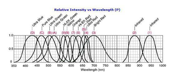
16 Question 5 (2 Points) Diode Circuits a. (3 Pts) We wish to regulate a 12V DC power supply using a Zener Diode from the table at the beginning of this quiz. Like all Zeners, this diode has three voltage ranges shown in I-V curve below: the Breakdown Region, The Forward Bias Region and the Reverse Bias Region. Assuming ideal conditions for this diode, complete the following i. The voltage across the diode is V D.7V in the Forward Bias Region ii. The voltage across the diode is V D 12V in the Breakdown Region iii. The current through the diode is I D A in the Reverse Bias Region b. (3 Pts) What is the current through the LED below, if we use the specified green LED? (Choose the closest answer.) i. 6 ma ii. 9 ma ii. 11 ma v. 14 ma v. 15 ma Super Lime Green, 57nm (9-2)/47 = 14.9mA 15mA 16 K. A. Connor

 The voltage across each forward-biased diode in the full-wave rectifier above is i. Near the source voltage ii. Near twice the source voltage iii.")
17 c. (4 Pts) This problem is similar to a task from Experiment 8 with a triangular wave input voltage. The input voltage is plotted below with the vertical scale going from -5V to +5V. Plot the voltage that results across the load resistor R2 and carefully label key values. Assume the positive probe is located to the left of R2 and the negative probe to the right. R1 5 V1 = 5V V2 = -5V TD = V1 D1 D1N4148 R2 D4 D1N4148 TR = 1ms 1k TF = 1ms PW = D3 D1N4148 D2 D1N4148 PER = 2ms Flat spot occurs because finite voltage is required to turn diode on. ( 5 1.4) = 3.6 = 2.4V d. (3 Pts) The voltage across each forward-biased diode in the full-wave rectifier above is i. Near the source voltage ii. Near twice the source voltage iii. Near half the source voltage iv. Near.6 to.7 volts v. Near zero volts 17 K. A. Connor

18 e. (4 Pts) We now want to use multiple LEDs like a short string of holiday lights. For this purpose, we will use four different color LEDs: Red, Green, Yellow and White. We will use the four LEDs marked with a in the table above. For the power supply, we will use one of two universal AC adapters available online that can output one of the following voltages (switch selectable). Universal AC Adapter: 15V 16V 18V 18.5V 19V 19.5V 2V 22V 24V 7W Universal AC Adapter: 3V 4.5V 6V 7.5V 9V 12V 1W Determine the voltage Vww and resistance R to achieve the desired operating conditions for the series combination of 4 LEDs shown below. Assume that the current is 25mA, since we have decided to slightly over drive our LEDs. Use the typical forward bias voltages from the table. The power supply voltage should be the minimum value that will turn on all of the LEDs. Dr Dg Dy Dw Vww R 1k Sum of forward voltages is = 11.4 so the 12V source is required. ( )/(.25) =.6/.25 = 24Ω f. (3 Pts) Shown below is a 1N75 Zener diode working to regulate the voltage across one resistor in a voltage divider. Determine the power dissipated by the Zener diode. 12Vdc Vdc Ra 1k Rb 1k Dz D1N75 When regulating, V Z = 4.7V. The current from the source is (12-4.7) = 7.3mA. The current through Rb is 4.7mA so the current through the Zener is ( ) = 2.6mA so the power dissipated by the Zener is 4.7(2.6)mW = 12.2mW 18 K. A. Connor
ENGR-4300 Electronic Instrumentation Quiz 3 Fall 2010 Name Section
 ENGR-4300 Electronic Instrumentation Quiz 3 Fall 00 Name Section You are to complete 5 questions. Question I is required. You may select any four of the first five questions. You must indicate which of
ENGR-2300 Electronic Instrumentation Quiz 4 Fall 2012 Name
 ENGR-23 Quiz 4 Fall 212 ENGR-23 Electronic Instrumentation Quiz 4 Fall 212 Name Question I (25 points) Question II (25 points) Question III (25 points) Question IV (25 points) Total (1 points) On all questions:
ENGR-4300 Spring 2009 Test 4. Name SOLUTION. Section 1(MR 8:00) 2(TF 2:00) 3(MR 6:00) (circle one) Question I (20 points) Question II (20 points)
 2(TF 2:00) 3(MR 6:00) (circle one) Question I (20 points) Question II (20 points)") ENGR-43 Spring 29 Test 4 Name SOLUTION Section 1(MR 8:) 2(TF 2:) 3(MR 6:) (circle one) Question I (2 points) Question II (2 points) Question III (15 points) Question IV (25 points) Question V (2 points)
ENGR-43 Spring 29 Test 4 Name SOLUTION Section 1(MR 8:) 2(TF 2:) 3(MR 6:) (circle one) Question I (2 points) Question II (2 points) Question III (15 points) Question IV (25 points) Question V (2 points)
ENGR4300 Fall 2005 Test 4A. Name. Section. Question 1 (25 points) Question 2 (25 points) Question 3 (25 points) Question 4 (25 points)
 Question 2 (25 points) Question 3 (25 points) Question 4 (25 points)") ENGR4300 Fall 2005 Test 4A Name Section Question 1 (25 points) Question 2 (25 points) Question 3 (25 points) Question 4 (25 points) Total (100 points): Please do not write on the crib sheets. On all questions:
ENGR4300 Fall 2005 Test 4A Name Section Question 1 (25 points) Question 2 (25 points) Question 3 (25 points) Question 4 (25 points) Total (100 points): Please do not write on the crib sheets. On all questions:
ENGR-4300 Electronic Instrumentation Quiz 3 Spring 2011 Name Section
 ENGR-400 Electronic Instrumentation Quiz Spring 0 Name Section Question I (0 points) Question II (0 points) Question III (0 points) Question IV (0 points) Question V (0 points) Total (00 points) On all
ENGR-4300 Fall 2006 Project 3 Project 3 Build a 555-Timer
 ENGR-43 Fall 26 Project 3 Project 3 Build a 555-Timer For this project, each team, (do this as team of 4,) will simulate and build an astable multivibrator. However, instead of using the 555 timer chip,
ENGR-4300 Fall 2008 Test 3. Name. Section 1(MR 8:00) 2(TF 2:00) (circle one) Question I (20 points) Question II (15 points) Question III (20 points)
 2(TF 2:00) (circle one) Question I (20 points) Question II (15 points) Question III (20 points)") ENGR-43 Fall 8 Test 3 Name Section (MR 8:) (TF :) (circle one) Question I ( points) Question II (5 points) Question III ( points) Question I ( points) Question (5 points) Total ( points): On all questions:
ENGR-43 Fall 8 Test 3 Name Section (MR 8:) (TF :) (circle one) Question I ( points) Question II (5 points) Question III ( points) Question I ( points) Question (5 points) Total ( points): On all questions:
ENGR4300 Fall 2005 Test 4A. Name solutions. Section. Question 1 (25 points) Question 2 (25 points) Question 3 (25 points) Question 4 (25 points)
 Question 2 (25 points) Question 3 (25 points) Question 4 (25 points)") ENGR4300 Fall 2005 Test 4A Name solutions Section Question 1 (25 points) Question 2 (25 points) Question 3 (25 points) Question 4 (25 points) Total (100 points): Please do not write on the crib sheets.
ENGR4300 Fall 2005 Test 4A Name solutions Section Question 1 (25 points) Question 2 (25 points) Question 3 (25 points) Question 4 (25 points) Total (100 points): Please do not write on the crib sheets.
Electronic Instrumentation. Experiment 8: Diodes (continued) Project 4: Optical Communications Link
 Project 4: Optical Communications Link") Electronic Instrumentation Experiment 8: Diodes (continued) Project 4: Optical Communications Link Agenda Brief Review: Diodes Zener Diodes Project 4: Optical Communication Link Why optics? Understanding
Electronic Instrumentation Experiment 8: Diodes (continued) Project 4: Optical Communications Link Agenda Brief Review: Diodes Zener Diodes Project 4: Optical Communication Link Why optics? Understanding
ENGR4300 Spring 2006 Test 4B. Name solution. Section 3 and 4. Question 1 (25 points) This is worth 20 not 25
 This is worth 20 not 25") ENGR4300 Spring 2006 Test 4B Name solution Section 3 and 4 Question 1 (25 points) This is worth 20 not 25 Question 2 (15 points) This is worth 20 not 15 Question 3 (20 points) Question 4 (20 points) Question
ENGR4300 Spring 2006 Test 4B Name solution Section 3 and 4 Question 1 (25 points) This is worth 20 not 25 Question 2 (15 points) This is worth 20 not 15 Question 3 (20 points) Question 4 (20 points) Question
ENGR-2300 Electronic Instrumentation Quiz 3 Spring Name: Solution Please write you name on each page. Section: 1 or 2
 ENGR-2300 Electronic Instrumentation Quiz 3 Spring 2018 Name: Solution Please write you name on each page Section: 1 or 2 4 Questions Sets, 20 Points Each LMS Portion, 20 Points Question Set 1) Question
Project 3 Build a 555-Timer
 Project 3 Build a 555-Timer For this project, each group will simulate and build an astable multivibrator. However, instead of using the 555 timer chip, you will have to use the devices you learned about
ENGR-4300 Electronic Instrumentation Quiz 2 Fall 2011 Name Section
 ENGR-43 Quiz 2 Fall 211 ENGR-43 Electronic Instrumentation Quiz 2 Fall 211 Name Section Question I (2 points) Question II (2 points) Question III (2 points) Question I (2 points) Question (2 points) Total
ENGR-4300 Fall 2008 Test 4. Name SOLUTION. Section 1(MR 8:00) 2(TF 2:00) (circle one) Question I (20 points) Question II (20 points)
 2(TF 2:00) (circle one) Question I (20 points) Question II (20 points)") ENGR-43 Fall 28 Test 4 Name SOLUTION Section 1(MR 8:) 2(TF 2:) (circle one) Question I (2 points) Question II (2 points) Question III (15 points) Question IV (2 points) Question V (25 points) Total (1
ENGR-43 Fall 28 Test 4 Name SOLUTION Section 1(MR 8:) 2(TF 2:) (circle one) Question I (2 points) Question II (2 points) Question III (15 points) Question IV (2 points) Question V (25 points) Total (1
Project 4 Optical Communications Link
 Project 4 Optical Communications Link Pulse Frequency Modulation Figure 1. In this project you will build optical transmitter and receiver circuits. The transmitter circuit uses pulse frequency modulation
Electronic Instrumentation ENGR-4300 Fall Project 4: Optical Communications Link
 Project 4: Optical Communications Link In this project you will build a transmitter and a receiver circuit. The transmitter circuit uses pulse frequency modulation to create a series of light pulses that
ENGR-2300 Electronic Instrumentation Quiz 2 Spring 2016
 ENGR-23 Quiz 2 Spring 216 ENGR-23 Electronic Instrumentation Quiz 2 Spring 216 On all questions: SHOW ALL WORK. BEGIN WITH FORMULAS, THEN SUBSTITUTE VALUES AND UNITS. No credit will be given for numbers
Electronic Instrumentation
 Electronic Instrumentation Project 4: Optical Communication Link 1. Optical Communications 2. Initial Design 3. PSpice Model 4. Final Design 5. Project Report Why use optics? Advantages of optical communication
ENGR4300 Test 3A Fall 2002
 1. 555 Timer (20 points) Figure 1: 555 Timer Circuit For the 555 timer circuit in Figure 1, find the following values for R1 = 1K, R2 = 2K, C1 = 0.1uF. Show all work. a) (4 points) T1: b) (4 points) T2:
0 0 Q Q Q Q
 Question 1) Flip Flops and Counters (15 points) a) Fill in the truth table for a JK flip flop. Use Q or Q to denote the previous value of Q and Q. (6 pts) J K CLK Q Q Q Q 1 1 1 1 1 1 Q Q b) In Figure 1a
B.E. SEMESTER III (ELECTRICAL) SUBJECT CODE: X30902 Subject Name: Analog & Digital Electronics
 SUBJECT CODE: X30902 Subject Name: Analog & Digital Electronics") B.E. SEMESTER III (ELECTRICAL) SUBJECT CODE: X30902 Subject Name: Analog & Digital Electronics Sr. No. Date TITLE To From Marks Sign 1 To verify the application of op-amp as an Inverting Amplifier 2 To
B.E. SEMESTER III (ELECTRICAL) SUBJECT CODE: X30902 Subject Name: Analog & Digital Electronics Sr. No. Date TITLE To From Marks Sign 1 To verify the application of op-amp as an Inverting Amplifier 2 To
ECE 2274 Pre-Lab for Experiment # 4 Diode Basics and a Rectifier Completed Prior to Coming to Lab
 Part I I-V Characteristic Curve ECE 2274 Pre-Lab for Experiment # 4 Diode Basics and a Rectifier Completed Prior to Coming to Lab 1. Construct the circuit shown in figure 4-1. Using a DC Sweep, simulate
Facility of Engineering. Biomedical Engineering Department. Medical Electronic Lab BME (317) Post-lab Forms
 Post-lab Forms") Facility of Engineering Biomedical Engineering Department Medical Electronic Lab BME (317) Post-lab Forms Prepared by Eng.Hala Amari Spring 2014 Facility of Engineering Biomedical Engineering Department
Facility of Engineering Biomedical Engineering Department Medical Electronic Lab BME (317) Post-lab Forms Prepared by Eng.Hala Amari Spring 2014 Facility of Engineering Biomedical Engineering Department
ENGR4300 Test 4A Spring 2005
 Question 1 Diodes Assume that the forward bias threshold voltage for the diode in the circuit is 0.7V. A. Consider the following circuit a) What type of diode circuit is the circuit above? (1 pt) half
ENGR4300 Test 3A and 3B Fall 2003
 Question 1 -- Astable Multivibrator R1 8 X1 18 1 1 2 U3 R2 TOPEN = 0 2 4 5 6 7 CC TRIGGER RESETOUTPUT CONTROL THRESHOLD DISCHARGE GND 555D R3 1Meg C1 C2 10uF.01uF 1 3 0 The circuit above has been simulated
Electronic Instrumentation
 5V 1 1 1 2 9 10 7 CL CLK LD TE PE CO 15 + 6 5 4 3 P4 P3 P2 P1 Q4 Q3 Q2 Q1 11 12 13 14 2-14161 Electronic Instrumentation Experiment 7 Digital Logic Devices and the 555 Timer Part A: Basic Logic Gates Part
ENGR-2300 Quiz 2 Fall ENGR-2300 Electronic Instrumentation Quiz 2 Fall Solution. Name Section. Question III (25 points)
") ENGR-23 Quiz 2 Fall 212 ENGR-23 Electronic Instrumentation Quiz 2 Fall 212 Solution Name Section Question I (25 points) Question II (25 points) Question III (25 points) Question IV (25 points) Total (1
ENGR-23 Quiz 2 Fall 212 ENGR-23 Electronic Instrumentation Quiz 2 Fall 212 Solution Name Section Question I (25 points) Question II (25 points) Question III (25 points) Question IV (25 points) Total (1
Lab 2 Revisited Exercise
 Lab 2 Revisited Exercise +15V 100k 1K 2N2222 Wire up led display Note the ground leads LED orientation 6.091 IAP 2008 Lecture 3 1 Comparator, Oscillator +5 +15 1k 2 V- 7 6 Vin 3 V+ 4 V o Notice that power
UNIVERSITY OF NORTH CAROLINA AT CHARLOTTE. Department of Electrical and Computer Engineering
 UNIVERSITY OF NORTH CAROLINA AT CHARLOTTE Department of Electrical and Computer Engineering Experiment No. 2 - Semiconductor Diodes Overview: In this lab session students will investigate I-V characteristics
Process Components. Process component
 What are PROCESS COMPONENTS? Input Transducer Process component Output Transducer The input transducer circuits are connected to PROCESS COMPONENTS. These components control the action of the OUTPUT components
ENGR-4300 Spring 2008 Test 3. Name SOLUTION. Section 1(MR 8:00) 2(TF 2:00) 3(MR 6:00) (circle one) Question I (20 points) Question II (20 points)
 2(TF 2:00) 3(MR 6:00) (circle one) Question I (20 points) Question II (20 points)") NGR- Test Spring 8 NGR- Spring 8 Test Name SOLUTION Section MR 8: TF : MR 6: circle one Question I points Question II points Question III points Question IV 5 points Question V 5 points Total points: On
NGR- Test Spring 8 NGR- Spring 8 Test Name SOLUTION Section MR 8: TF : MR 6: circle one Question I points Question II points Question III points Question IV 5 points Question V 5 points Total points: On
ENGR-4300 Spring 2008 Test 4. Name SOLUTION. Section 1(MR 8:00) 2(TF 2:00) 3(MR 6:00) (circle one) Question I (24 points) Question II (16 points)
 2(TF 2:00) 3(MR 6:00) (circle one) Question I (24 points) Question II (16 points)") ENGR-4300 Spring 2008 Test 4 Name SOLUTION Section 1(MR 8:00) 2(TF 2:00) 3(MR 6:00) (circle one) Question I (24 points) Question II (16 points) Question III (15 points) Question IV (20 points) Question
ENGR-4300 Spring 2008 Test 4 Name SOLUTION Section 1(MR 8:00) 2(TF 2:00) 3(MR 6:00) (circle one) Question I (24 points) Question II (16 points) Question III (15 points) Question IV (20 points) Question
Name. Draw circuit diagrams for all problems, especially as you simplify the circuits.
 Quiz I Spring 2016 Name Part B (80 Points) 1. (10 Pts) 2. (15 Pts) 3. (10 Pts) 4. (10 Pts) 5. (5 Pts) 6. (10 Pts) 7. (16 Pts) 8. (4 Pts) Total Draw circuit diagrams for all problems, especially as you
Electronic Switching Concept Issue
 Electronic Switching Concept Issue The following is a discussion of one of the more complex tasks in Experiment 6, where you are asked to find the values of the voltages at five points for the upper and
ELE1. ELECTRONICS Unit 1 Foundation Electronics. General Certificate of Education June 2004 Advanced Subsidiary Examination
 Surname Centre Number Other Names Candidate Number Leave blank Candidate Signature General Certificate of Education June 2004 Advanced Subsidiary Examination ELECTRONICS Unit 1 Foundation Electronics ELE1
ENGR-2300 Electronic Instrumentation Quiz 1 Fall 2018 Name SOLUTIONS Section. Question III (20 points)
") ENGR-2300 Electronic Instrumentation Quiz 1 Fall 2018 Name SOLUTIONS Section Question I (20 points) Question II (20 points) Question III (20 points) Question IV (20 points) LMS Question (20 points) (graded
ENGR-2300 Electronic Instrumentation Quiz 1 Fall 2018 Name SOLUTIONS Section Question I (20 points) Question II (20 points) Question III (20 points) Question IV (20 points) LMS Question (20 points) (graded
EXPERIMENT 7: DIODE CHARACTERISTICS AND CIRCUITS 10/24/10
 DIODE CHARACTERISTICS AND CIRCUITS EXPERIMENT 7: DIODE CHARACTERISTICS AND CIRCUITS 10/24/10 In this experiment we will measure the I vs V characteristics of Si, Ge, and Zener p-n junction diodes, and
University of Pittsburgh
 University of Pittsburgh Experiment #5 Lab Report Diode Applications and PSPICE Introduction Submission Date: 10/10/2017 Instructors: Dr. Minhee Yun John Erickson Yanhao Du Submitted By: Nick Haver & Alex
Electronics. RC Filter, DC Supply, and 555
 Electronics RC Filter, DC Supply, and 555 0.1 Lab Ticket Each individual will write up his or her own Lab Report for this two-week experiment. You must also submit Lab Tickets individually. You are expected
Name. Part A (25 Points) Complete on Blackboard. A. (25 Pts) Part B (75 Points) 1. (12 Pts) 2. (12 Pts) 3. (10 Pts) 4. (8 Pts) 5. (11 Pts) 6.
 Complete on Blackboard. A. (25 Pts) Part B (75 Points) 1. (12 Pts) 2. (12 Pts) 3. (10 Pts) 4. (8 Pts) 5. (11 Pts) 6.") Name Part A (25 Points) Complete on Blackboard A. (25 Pts) Part B (75 Points) 1. (12 Pts) 2. (12 Pts) 3. (10 Pts) 4. (8 Pts) 5. (11 Pts) 6. (6 Pts) 7. (13 Pts) 8. (3 Pts) Total Annotate the circuit diagrams
Name Part A (25 Points) Complete on Blackboard A. (25 Pts) Part B (75 Points) 1. (12 Pts) 2. (12 Pts) 3. (10 Pts) 4. (8 Pts) 5. (11 Pts) 6. (6 Pts) 7. (13 Pts) 8. (3 Pts) Total Annotate the circuit diagrams
Purpose: 1) to investigate the electrical properties of a diode; and 2) to use a diode to construct an AC to DC converter.
 to investigate the electrical properties of a diode; and 2) to use a diode to construct an AC to DC converter.") Name: Partner: Partner: Partner: Purpose: 1) to investigate the electrical properties of a diode; and 2) to use a diode to construct an AC to DC converter. The Diode A diode is an electrical device which
Name: Partner: Partner: Partner: Purpose: 1) to investigate the electrical properties of a diode; and 2) to use a diode to construct an AC to DC converter. The Diode A diode is an electrical device which
LABORATORY 3: Transient circuits, RC, RL step responses, 2 nd Order Circuits
 LABORATORY 3: Transient circuits, RC, RL step responses, nd Order Circuits Note: If your partner is no longer in the class, please talk to the instructor. Material covered: RC circuits Integrators Differentiators
Applications of diodes
 Applications of diodes Learners should be able to: (a) describe the I V characteristics of a silicon diode (b) describe the use of diodes for component protection in DC circuits and half-wave rectification
LIC & COMMUNICATION LAB MANUAL
 LIC & Communication Lab Manual LIC & COMMUNICATION LAB MANUAL FOR V SEMESTER B.E (E& ( E&C) (For private circulation only) NAME: DEPARTMENT OF ELECTRONICS & COMMUNICATION SRI SIDDHARTHA INSTITUTE OF TECHNOLOGY
GCE AS. WJEC Eduqas GCE AS in ELECTRONICS ACCREDITED BY OFQUAL DESIGNATED BY QUALIFICATIONS WALES SAMPLE ASSESSMENT MATERIALS
 GCE AS WJEC Eduqas GCE AS in ELECTRONICS ACCREDITED BY OFQUAL DESIGNATED BY QUALIFICATIONS WALES SAMPLE ASSESSMENT MATERIALS Teaching from 207 For award from 208 AS ELECTRONICS Sample Assessment Materials
After performing this experiment, you should be able to:
 Objectives: After performing this experiment, you should be able to: Demonstrate the strengths and weaknesses of the two basic rectifier circuits. Draw the output waveforms for the two basic rectifier
Analog Electronic Circuits Lab-manual
 2014 Analog Electronic Circuits Lab-manual Prof. Dr Tahir Izhar University of Engineering & Technology LAHORE 1/09/2014 Contents Experiment-1:...4 Learning to use the multimeter for checking and indentifying
ENGR 210 Lab 12: Analog to Digital Conversion
 ENGR 210 Lab 12: Analog to Digital Conversion In this lab you will investigate the operation and quantization effects of an A/D and D/A converter. A. BACKGROUND 1. LED Displays We have been using LEDs
PESIT BANGALORE SOUTH CAMPUS BASIC ELECTRONICS
 PESIT BANGALORE SOUTH CAMPUS QUESTION BANK BASIC ELECTRONICS Sub Code: 17ELN15 / 17ELN25 IA Marks: 20 Hrs/ Week: 04 Exam Marks: 80 Total Hours: 50 Exam Hours: 03 Name of Faculty: Mr. Udoshi Basavaraj Module
ECE 2274 Diode Basics and a Rectifier Completed Prior to Coming to Lab
 ECE 2274 Diode Basics and a Rectifier Completed Prior to Coming to Lab Perlab: Part I I-V Characteristic Curve for the 1. Construct the circuit shown in figure 1. Using a DC Sweep, simulate in LTspice
ANALOG TO DIGITAL CONVERTER
 Final Project ANALOG TO DIGITAL CONVERTER As preparation for the laboratory, examine the final circuit diagram at the end of these notes and write a brief plan for the project, including a list of the
OBJECTIVE The purpose of this exercise is to design and build a pulse generator.
 ELEC 4 Experiment 8 Pulse Generators OBJECTIVE The purpose of this exercise is to design and build a pulse generator. EQUIPMENT AND PARTS REQUIRED Protoboard LM555 Timer, AR resistors, rated 5%, /4 W,
EE 2274 DIODE OR GATE & CLIPPING CIRCUIT
 EE 2274 DIODE OR GATE & CLIPPING CIRCUIT Prelab Part I: Wired Diode OR Gate LTspice use 1N4002 1. Design a diode OR gate, Figure 1 in which the maximum current thru R1 I R1 = 9mA assume Vin = 5Vdc. Design
Electronic Instrumentation ENGR-4300 Fall 2004 Section Experiment 7 Introduction to the 555 Timer, LEDs and Photodiodes
 Experiment 7 Introduction to the 555 Timer, LEDs and Photodiodes Purpose: In this experiment, we learn a little about some of the new components which we will use in future projects. The first is the 555
THIRD SEMESTER ELECTRONICS - II BASIC ELECTRICAL & ELECTRONICS LAB DEPARTMENT OF ELECTRICAL ENGINEERING
 THIRD SEMESTER ELECTRONICS - II BASIC ELECTRICAL & ELECTRONICS LAB DEPARTMENT OF ELECTRICAL ENGINEERING Prepared By: Checked By: Approved By: Engr. Saqib Riaz Engr. M.Nasim Khan Dr.Noman Jafri Lecturer
1. LINEAR WAVE SHAPING
 Aim: 1. LINEAR WAVE SHAPING i) To design a low pass RC circuit for the given cutoff frequency and obtain its frequency response. ii) To observe the response of the designed low pass RC circuit for the
EE 3101 ELECTRONICS I LABORATORY EXPERIMENT 9 LAB MANUAL APPLICATIONS OF IC BUILDING BLOCKS
 EE 3101 ELECTRONICS I LABORATORY EXPERIMENT 9 LAB MANUAL APPLICATIONS OF IC BUILDING BLOCKS OBJECTIVES In this experiment you will Explore the use of a popular IC chip and its applications. Become more
Revised: Summer 2010
 EE 2274 PRE-LAB EXPERIMENT 5 DIODE OR GATE & CLIPPING CIRCUIT COMPLETE PRIOR TO COMING TO LAB Part I: 1. Design a diode, Figure 1 OR gate in which the maximum input current,, Iin is less than 5mA. Show
DEPARTMENT OF ELECTRICAL ENGINEERING LAB WORK EE301 ELECTRONIC CIRCUITS
 DEPARTMENT OF ELECTRICAL ENGINEERING LAB WORK EE301 ELECTRONIC CIRCUITS EXPERIMENT : 4 TITLE : 555 TIMERS OUTCOME : Upon completion of this unit, the student should be able to: 1. gain experience with
Electronic Instrumentation ENGR-4300 Fall 2002 Project 2: Optical Communications Link
 Project 2: Optical Communications Link For this project, each group will build a transmitter circuit and a receiver circuit. It is suggested that 1 or 2 students build and test the individual components
EXPERIMENT 3 Half-Wave and Full-Wave Rectification
 Name & Surname: ID: Date: EXPERIMENT 3 Half-Wave and Full-Wave Rectification Objective To calculate, compare, draw, and measure the DC output voltages of half-wave and full-wave rectifier circuits. Tools
Exam Booklet. Pulse Circuits
 Exam Booklet Pulse Circuits Pulse Circuits STUDY ASSIGNMENT This booklet contains two examinations for the six lessons entitled Pulse Circuits. The material is intended to provide the last training sought
Problem 1: Voltage Limiting 1.1. Simulate the following simple resistor-diode circuit (shown on the left in Figure 1):
:") EEE 33 Electronics I (Summer 218) PSPICE: Diode Applications Diode Limiters, Rectifiers and Voltage Regulation (Due Tuesday, June 26, 218) Homework 2 Problem 1: Voltage Limiting 1.1. Simulate the following
EEE 33 Electronics I (Summer 218) PSPICE: Diode Applications Diode Limiters, Rectifiers and Voltage Regulation (Due Tuesday, June 26, 218) Homework 2 Problem 1: Voltage Limiting 1.1. Simulate the following
Physics 120 Lab 6 (2018) - Field Effect Transistors: Ohmic Region
 - Field Effect Transistors: Ohmic Region") Physics 120 Lab 6 (2018) - Field Effect Transistors: Ohmic Region The field effect transistor (FET) is a three-terminal device can be used in two extreme ways as an active element in a circuit. One is
Physics 120 Lab 6 (2018) - Field Effect Transistors: Ohmic Region The field effect transistor (FET) is a three-terminal device can be used in two extreme ways as an active element in a circuit. One is
GCSE (9-1) WJEC Eduqas GCSE (9-1) in ELECTRONICS ACCREDITED BY OFQUAL DESIGNATED BY QUALIFICATIONS WALES SAMPLE ASSESSMENT MATERIALS
 WJEC Eduqas GCSE (9-1) in ELECTRONICS ACCREDITED BY OFQUAL DESIGNATED BY QUALIFICATIONS WALES SAMPLE ASSESSMENT MATERIALS") GCSE (9-1) WJEC Eduqas GCSE (9-1) in ELECTRONICS ACCREDITED BY OFQUAL DESIGNATED BY QUALIFICATIONS WALES SAMPLE ASSESSMENT MATERIALS Teaching from 2017 For award from 2019 GCSE ELECTRONICS Sample Assessment
GCSE (9-1) WJEC Eduqas GCSE (9-1) in ELECTRONICS ACCREDITED BY OFQUAL DESIGNATED BY QUALIFICATIONS WALES SAMPLE ASSESSMENT MATERIALS Teaching from 2017 For award from 2019 GCSE ELECTRONICS Sample Assessment
Dev Bhoomi Institute Of Technology Department of Electronics and Communication Engineering PRACTICAL INSTRUCTION SHEET
 Dev Bhoomi Institute Of Technology Department of Electronics and Communication Engineering PRACTICAL INSTRUCTION SHEET LABORATORY MANUAL EXPERIMENT NO. ISSUE NO. : ISSUE DATE: REV. NO. : REV. DATE : PAGE:
EE 110 Introduction to Engineering & Laboratory Experience Saeid Rahimi, Ph.D. Lab 6 Diodes: Half-Wave and Full-Wave Rectifiers Converting AC to DC
 EE 110 Introduction to Engineering & Laboratory Experience Saeid Rahimi, Ph.D. Lab 6 Diodes: Half-Wave and Full-Wave Rectifiers Converting C to DC The process of converting a sinusoidal C voltage to a
Prelab 6: Biasing Circuitry
 Prelab 6: Biasing Circuitry Name: Lab Section: R 1 R 2 V OUT Figure 1: Resistive divider voltage source 1. Consider the resistor network shown in Figure 1. Let = 10 V, R 1 = 9.35 kω, and R 2 = 650 Ω. We
Class #8: Experiment Diodes Part I
 Class #8: Experiment Diodes Part I Purpose: The objective of this experiment is to become familiar with the properties and uses of diodes. We used a 1N914 diode in two previous experiments, but now we
Multivibrators. Department of Electrical & Electronics Engineering, Amrita School of Engineering
 Multivibrators Multivibrators Multivibrator is an electronic circuit that generates square, rectangular, pulse waveforms. Also called as nonlinear oscillators or function generators. Multivibrator is basically
DEPARTMENT OF ELECTRICAL ENGINEERING AND COMPUTER SCIENCE MASSACHUSETTS INSTITUTE OF TECHNOLOGY CAMBRIDGE, MASSACHUSETTS 02139
 DEPARTMENT OF ELECTRICAL ENGINEERING AND COMPUTER SCIENCE MASSACHUSETTS INSTITUTE OF TECHNOLOGY CAMBRIDGE, MASSACHUSETTS 019.101 Introductory Analog Electronics Laboratory Laboratory No. READING ASSIGNMENT
Facility of Engineering. Biomedical Engineering Department. Medical Electronic Lab BME (317) Pre-Report Forms
 Pre-Report Forms") Facility of Engineering Biomedical Engineering Department Medical Electronic Lab BME (317) Pre-Report Forms Prepared by Eng.Hala Amari Spring 2014 Facility of Engineering Biomedical Engineering Department
Facility of Engineering Biomedical Engineering Department Medical Electronic Lab BME (317) Pre-Report Forms Prepared by Eng.Hala Amari Spring 2014 Facility of Engineering Biomedical Engineering Department
Concepts to be Covered
 Introductory Medical Device Prototyping Analog Circuits Part 2 Semiconductors, http://saliterman.umn.edu/ Department of Biomedical Engineering, University of Minnesota Concepts to be Covered Semiconductors
NORTHWESTERN UNIVERSITY TECHNOLOGICAL INSTITUTE
 NORTHWESTERN UNIVERSITY TECHNOLOGICAL INSTITUTE ECE-270 Experiment #4 X-Y DISPLAY TECHNIQUES: DIODE CHARACTERISTICS PRELAB Use your textbook and/or the library to answer the following questions about diodes.
GATE SOLVED PAPER - IN
 YEAR 202 ONE MARK Q. The i-v characteristics of the diode in the circuit given below are : v -. A v 0.7 V i 500 07 $ = * 0 A, v < 0.7 V The current in the circuit is (A) 0 ma (C) 6.67 ma (B) 9.3 ma (D)
Electronics and Instrumentation Name ENGR-4220 Fall 1998 Section Quiz 2
 Quiz 2 1. RLC Circuits You should recognize the circuits shown below from Experiment 5 and Gingrich s notes. Given below are several possible expressions for transfer functions for such circuits. Indicate
Department of Electrical & Computer Engineering Technology. EET 3086C Circuit Analysis Laboratory Experiments. Masood Ejaz
 Department of Electrical & Computer Engineering Technology EET 3086C Circuit Analysis Laboratory Experiments Masood Ejaz Experiment # 1 DC Measurements of a Resistive Circuit and Proof of Thevenin Theorem
OBJECTIVE TYPE QUESTIONS
 OBJECTIVE TYPE QUESTIONS Q.1 The breakdown mechanism in a lightly doped p-n junction under reverse biased condition is called (A) avalanche breakdown. (B) zener breakdown. (C) breakdown by tunnelling.
Basic Operational Amplifier Circuits
 Basic Operational Amplifier Circuits Comparators A comparator is a specialized nonlinear op-amp circuit that compares two input voltages and produces an output state that indicates which one is greater.
NJM4151 V-F / F-V CONVERTOR
 V-F / F-V CONVERTOR GENERAL DESCRIPTION PACKAGE OUTLINE The NJM4151 provide a simple low-cost method of A/D conversion. They have all the inherent advantages of the voltage-to-frequency conversion technique.
Assume availability of the following components to DESIGN and DRAW the circuits of the op. amp. applications listed below:
 ========================================================================================== UNIVERSITY OF SOUTHERN MAINE Dept. of Electrical Engineering TEST #3 Prof. M.G.Guvench ELE343/02 ==========================================================================================
HIGH LOW Astable multivibrators HIGH LOW 1:1
 1. Multivibrators A multivibrator circuit oscillates between a HIGH state and a LOW state producing a continuous output. Astable multivibrators generally have an even 50% duty cycle, that is that 50% of
EXPERIMENT 2.2 NON-LINEAR OP-AMP CIRCUITS
 2.16 EXPERIMENT 2.2 NONLINEAR OPAMP CIRCUITS 2.2.1 OBJECTIVE a. To study the operation of 741 opamp as comparator. b. To study the operation of active diode circuits (precisions circuits) using opamps,
). The THRESHOLD works in exactly the opposite way; whenever the THRESHOLD input is above 2/3V CC
. The THRESHOLD works in exactly the opposite way; whenever the THRESHOLD input is above 2/3V CC") ENGR 210 Lab 8 RC Oscillators and Measurements Purpose: In the previous lab you measured the exponential response of RC circuits. Typically, the exponential time response of a circuit becomes important
ENGR 210 Lab 8 RC Oscillators and Measurements Purpose: In the previous lab you measured the exponential response of RC circuits. Typically, the exponential time response of a circuit becomes important
Difference between BJTs and FETs. Junction Field Effect Transistors (JFET)
") Difference between BJTs and FETs Transistors can be categorized according to their structure, and two of the more commonly known transistor structures, are the BJT and FET. The comparison between BJTs
Difference between BJTs and FETs Transistors can be categorized according to their structure, and two of the more commonly known transistor structures, are the BJT and FET. The comparison between BJTs
ECE 454 Homework #1 Due 11/28/2018 This Wednesday In Lab
 ECE 454 Homework #1 Due 11/28/2018 This Wednesday In Lab Design the Darlington push-pull amplifier specified in Lab 1: You will build this amplifier for Lab 1 so use parts that are available in the lab.
Since transmission lines can be modeled using PSpice, you can do your analysis by downloading the student version of this excellent program.
 PSpice Analysis Since transmission lines can be modeled using PSpice, you can do your analysis by downloading the student version of this excellent program. PSpice can be downloaded from the following
Name. For partial credit in some question, you may want to re-draw circuit diagrams as you simplify the circuits.
 Quiz I Fall 2017 Name Part B (80 Points) 1. (10 Pts) 2. (8 Pts) 3. (16 Pts) 5. (12 Pts) 6. (16 Pts) 7. (11 Pts) 4. (7 Pts) Total Be sure to simplify circuits into standard forms. For partial credit in
Lab 11: 555 Timer/Oscillator Circuits
 Page 1 of 6 Laboratory Goals Familiarize students with the 555 IC and its uses Design a free-running oscillator Design a triggered one-shot circuit Compare actual to theoretical values for the circuits
Summer 2015 Examination
 Summer 2015 Examination Subject Code: 17445 Model Answer Important Instructions to examiners: 1) The answers should be examined by key words and not as word-to-word as given in the model answer scheme.
LINEAR IC APPLICATIONS
 1 B.Tech III Year I Semester (R09) Regular & Supplementary Examinations December/January 2013/14 1 (a) Why is R e in an emitter-coupled differential amplifier replaced by a constant current source? (b)
DEPARTMENT OF ELECTRICAL ENGINEERING AND COMPUTER SCIENCE MASSACHUSETTS INSTITUTE OF TECHNOLOGY CAMBRIDGE, MASSACHUSETTS 02139
 DEPARTMENT OF ELECTRICAL ENGINEERING AND COMPUTER SCIENCE MASSACHUSETTS INSTITUTE OF TECHNOLOGY CAMBRIDGE, MASSACHUSETTS 019 Spring Term 00.101 Introductory Analog Electronics Laboratory Laboratory No.
Field Effect Transistors
 Field Effect Transistors Purpose In this experiment we introduce field effect transistors (FETs). We will measure the output characteristics of a FET, and then construct a common-source amplifier stage,
Federal Urdu University of Arts, Science & Technology Islamabad Pakistan SECOND SEMESTER ELECTRONICS - I
 SECOND SEMESTER ELECTRONICS - I BASIC ELECTRICAL & ELECTRONICS LAB DEPARTMENT OF ELECTRICAL ENGINEERING Prepared By: Checked By: Approved By: Engr. Yousaf Hameed Engr. M.Nasim Khan Dr.Noman Jafri Lecturer
ENGR-2300 Electronic Instrumentation Quiz 1 Spring 2016
 ENGR-2300 Electronic Instrumentation Quiz Spring 206 On all questions: SHOW ALL WORK. BEGIN WITH FORMULAS, THEN SUBSTITUTE ALUES AND UNITS. No credit will be given for numbers that appear without justification.
Lab Manual Rev 2. General Information: Lab Report Format: EE360, Fall03, Kolk
 Lab Manual Rev 2 EE360, Fall03, Kolk General Information: 1. The lab is located in Dana 115. Our lab assistant is Jun Kondo. Lab hours for EE360 are Monday evenings 7:00 9:00 pm. The lab is available after
CHAPTER 6 DIGITAL INSTRUMENTS
 CHAPTER 6 DIGITAL INSTRUMENTS 1 LECTURE CONTENTS 6.1 Logic Gates 6.2 Digital Instruments 6.3 Analog to Digital Converter 6.4 Electronic Counter 6.6 Digital Multimeters 2 6.1 Logic Gates 3 AND Gate The
SUMMER 13 EXAMINATION Subject Code: Model Answer Page No: / N
 Important Instructions to examiners: 1) The answers should be examined by key words and not as word-to-word as given in the model answer scheme. 2) The model answer and the answer written by candidate
Diode Applications Half-Wave Rectifying
 Lab 5 Diode Applications Half-Wave ectifying Objectives: Study the half-wave rectifying and smoothing with a capacitor for a simple diode circuit. Study the use of a Zener diode in a circuit with an AC
Electronic Concepts and Troubleshooting 101. Experiment 1
 Electronic Concepts and Troubleshooting 101 Experiment 1 o Concept: What is the capacity of a typical alkaline 1.5V D-Cell? o TS: Assume that a battery is connected to a 20Ω load and the voltage across