PIE 525B. Automated Thermocouple & RTD Calibrator Operating Instructions. Practical Instrument Electronics
|
|
|
- Oscar Maxwell
- 5 years ago
- Views:
Transcription


1 PIE 525B Automated Thermocouple & RTD Calibrator Operating Instructions Practical Instrument Electronics 82 East Main Street Suite 3.14 Webster, NY USA Tel: Fax:
2 Contents General Operations Connections... 4 Accessories... 5 Carrying Case, Boot... 6 Changing Batteries & Storing EZ-CHECK Outputs... 7 Basic Operation Switches & Knobs MAIN Menus - Functions, Units & Ranges FEATURE Menu - Stepping & Ramping / Auto Off FEATURE Menu - Stepping & Ramping / Backlight Functions and Hookup Diagrams Millivolt Source mv; Read mv... 14,15 Thermocouple Source T/C & Read T/C Sensors... 16,17 Resistance Source Resistance, Read Resistance... 18,19 RTD Source RTD & Read RTD Sensors...20, 21 Troubleshooting RTD Instruments Troubleshooting RTD Sensors Specifications General Thermocouple Ranges & Accuracies RTD Ranges & Accuracies Warranty Warranty & Additional Information... 37
3 General Information Calibrate all your T/C & RTD Instruments Easy to use With the PIE 525B you can check and calibrate all your thermocouple and RTD instruments and measure temperature sensors. Take it into the shop, plant or field Carry it without worry - it comes protected with a rubber boot and rugged, low profile switches. Easy to operate even in the dark areas of the plant with the backlit display. Calibrate T/C instruments to 0.1 & 0.01 F & C The PIE 525B works with the thermocouples you use including types J, K, T, E, R, S, B, N, G, C, D, L (J-DIN), U (T-DIN) and P (Platinel II). Or calibrate from to mv. Calibrate RTD instruments to 0.1 & 0.01 F & C Stop carrying around a decade box and RTD resistance tables. The 525B works with the RTDs you use including Platinum 10, 50, 100, 200, 500 & 1000 Ohm (alpha = 3850), Platinum 100 Ohm (alpha = 3902, 3916, 3926), Copper 10 & 50 Ohm, and Nickel 120 Ohm. Or calibrate from to and 0.00 to Ohms. Page 1
4 Fast calibration with automatic output stepping Easily set any value quickly to within 0.1 or 0.01 with the adjustable digital potentiometer DIAL plus store any three temperatures for instant recall with the EZ-CHECK switch. Choose between 2, 3, 5, 11 steps and ramp to automatically increment the output in 100%, 50%, 25%, 10% or 5% of span. Select step time from 5, 6, 7, 8, 9, 10, 15, 20, 25, 30 & 60 seconds. Compatible with ALL process instruments No competitor s calibrator is compatible with as many process instruments! Connect directly to the temperature inputs of transmitters, PLCs, DCS & multichannel recorders to verify their outputs or displays. RTD simulation works with older instruments with fixed excitation currents and newer multichannel instruments that switch the excitation current between input channels. Perform Heat Treating Uniformity Surveys and System Accuracy Tests The PIE 525B meets or exceeds the requirement of AMS 2750 as a Secondary Standard & as a Field Test Instrument. Measure thermocouple & RTD sensors The PIE 525B measures probes to 0.1 or 0.01 C or F. Secondary display shows the millivolt or resistance value corresponding to the sensor Page 2
5 temperature. For T/Cs the cold junction temperature measured by the calibrator. For RTDs the fixed or pulsed sensor current outputted by the measuring instrument is measured by the calibrator. Find problems with troubleshooting tools Open thermocouples and thermocouples that have high resistance indicating impending failure are indicated by OPEN TC on the display. Troubleshoot RTD sensor connections and find broken wires with patented technology. Connect your two, three or four wire RTDs and the PIE 525B automatically detects the connections. Calibration Lab Accurate & Stable The internal cold junction thermistor is accurate to ±0.05 C and is traceable to NIST. The sensor is thermally bonded to an isothermal mass which includes brass blocks with screw terminals for connection of bare thermocouple wires along with a miniature thermocouple connector for fast connections. The circuitry uses an extremely stable voltage reference and low drift components which make the PIE 525B more accurate than most other handheld and bench top thermocouple calibrators. Become a troubleshooting technician with Patented Diagnostic Technology - Available only with PIE Calibrators! Page 3

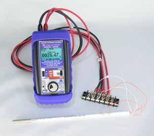
6 Connections Simulating or reading thermocouples requires the use of thermocouple or extension grade thermocouple wire. Plug thermocouple wires into the miniature jack or place bare thermocouple wires onto the brass block under the screws. The PIE 525B has two banana jacks (1+ & 2-) mounted in the top end of the housing. These are not temperature compensated and are to be used only for millivolt signals or thermocouple signals with the cold junction turned off. Simulating or reading RTDs uses copper wire. Plug 2, 3 or 4 wires into the corresponding jacks on the calibrator. For RTD source the PIE 525B simulates the (+) RTD from jacks 1 & 4 and the (-) RTD from jacks 2 & 3. When reading an RTD sensor the PIE 525B uses patented circuitry to automatically detect if 2, 3 or 4 wires are connected. This is helpful to troubleshoot sensor connection (see Troubleshooting an RTD Sensor). Page 4
7 Accessories INCLUDED: Four AA Alkaline batteries, Certificate of Calibration Evolution Hands Free Carrying Case Part No Dark Blue Rubber Boot Part No Test Leads - one pair with Part No banana plug & alligator clips Evolution RTD Wire Kit Part No Red & 2 Black Leads with Banana Plugs & Spade Lugs OPTIONAL: Ni-MH 1 Hour Charger with 4 Ni-MH AA Part No Batteries ( V AC input for North America Only) T/C Wire Kit 1* for Types J, K, T & E Part No T/C Wire Kit 2* for Types B, R/S & N Part No *Three feet (1 meter) of T/C extension wire, stripped on one end with a miniature T/C male connector on the other end. Magnet Strap Part No Page 5


8 Operating Instructions FIELD & BENCH USE PIE 525B comes with a carrying case designed for hands-free operation and a rubber boot with a built-in tilt stand. The PIE 525B is held in the case by elastic straps for use with the carrying case open. The tilt stand is easily raised by pulling the stand until it locks into place. Page 6
9 Operating Instructions CHANGING BATTERIES Low battery is indicated by a battery symbol on the display. Approximately one to four hours of typical operation remain before the PIE 525B will automatically turn off. To change the batteries remove the rubber boot and remove the battery door from the back of the unit by sliding the door downward. This allows access to the battery compartment. Replace with four (4) AA 1.5V batteries being careful to check the polarity. Replace the battery door and replace the boot. All stored configuration options (T/C Type, EZ-CHECK Memories, etc.) are reset to factory settings when the batteries are removed. Note: Alkaline batteries are supplied and recommended for typical battery life and performance. Optional rechargeable batteries (charged externally) are available. STORING HI and LO EZ-CHECK Source Outputs Speed up your calibration by storing Span & Zero output setting for instant recall with the EZ-CHECK switch. 1) Store your high (SPAN) output temperature by moving the EZ-CHECK switch to the HI position and turning the EZ-Dial knob until the desired output value is on the display. Press and hold the EZ-Dial knob until STORED appears to store the value. Release the EZ-Dial knob. 2) Store your low (ZERO) output value by moving the EZ-CHECK switch to the LO position and turning the EZ-Dial knob until the desired output value is on the display. Press and hold the EZ-Dial knob until STORED appears to store the value. Release the EZ-Dial knob. 3) Instantly output your SPAN and ZERO output settings by moving the EZ-CHECK switch between HI and LO. You may also select any third output setting (such as mid-range) using the SET position on the EZ-CHECK switch. Page 7
10 Operating Instructions Basic Operation 22.4 C mV T/C C HI TYPE K Automated RTD & Thermocouple Calibrator Pt 10, 50, 100, 200, 500 & 1000Ω Cu 10 & 50Ω Ni 120Ω J T E K R S B N G C D L U P mv HI SET LO MAX READ MIN + SOURCE OFF READ OVERLOAD Double Click Menu Push & Turn for Fast Dialing Push & Hold to Store/Step q EZ-CHECK SWITCH SOURCE: Instantly output two preset settings by moving the EZ-CHECK switch to the LO position or HI position. For fast three point checks select the SET position. The PIE 525B will remember the last SET value, even with the power off. These values can easily be changed to suit the calibration requirements. The values stored in the HI and LO positions are also used for Auto Stepping. READ: Slide the switch to the SET position. The PIE 525B will display the current reading from the sensor or device being measured. Slide the switch to MAX and the highest value measured since turn-on or reset will be displayed; slide the switch to MIN and the lowest value measured since turn-on or reset will be displayed. Page 8
11 Operating Instructions Basic Operation w SOURCE/OFF/READ Switch Select SOURCE to output mv, T/C, Ω or RTD. Select READ to read mv, T/C, Ω or RTD. Select OFF to turn off the 525B. e EZ-DIAL KNOB SOURCE: Turn the knob to adjust the output level. Turn clockwise to increase the output, counter clockwise to decrease the output in one least significant digit step at a time. Push down and turn the EZ-DIAL knob for faster dialing. Press and hold the knob for two seconds to store desired EZ-Check HI/LO points in SOURCE mode. Continue to press and hold the knob for two more seconds to start the automatic ramping. READ: Press and hold to transfer the current temperature into the EZ-Check MIN/MAX points. This clears the MIN/MAX readings which will update as the input value changes. SELECTING FUNCTIONS The EZ-DIAL knob is used to setup the PIE 525B to match the instrument to be calibrated or signal to be measured. Each time you turn on the PIE 525B the LCD displays the following screen for about 1 second followed by operating in the function used the last time it was operated. PIE 525B DOUBLE CLICK EZ-DIAL KNOB FOR CONFIGURATION Double Click the EZ-DIAL knob to change the function of the calibrator and to select ranges, units and other user settings. Each function (mv, T/C, Ohms, RTD) has up to three pages of menus. The first menu page has settings for the function and the last menu page has settings for STEPPING, AUTO OFF and BACKLIGHT. Settings are remembered even with the power off but are reset when the batteries are changed. Page 9
12 Operating Instructions Double Click Menus - MAIN Page Double click the EZ-DIAL knob to access the Double Click Menus. Shown are the MAIN menus for each function. Turn the knob to scroll thru the menus and press the knob to select. Default values are in black and available choices are shown in grey. Source V Read V >EXIT (1/3) >EXIT (1/3) FUNCTION V FUNCTION V RANGE 80mV RANGE 80mV Source & Read Thermocouples >EXIT (1/3) FUNCTION T/C UNITS C F T/C TYPE J K E T R S B N L U G C D P COLD JUNC ON OFF Source Ohms Read Ohms >EXIT (1/3) >EXIT (1/3) FUNCTION OHMS FUNCTION OHMS RANGE 400Ω 4000Ω RANGE 400Ω 4000Ω Source RTD >EXIT (1/3) FUNCTION RTD UNITS C F RTD Pt 100 a=3850 [*RTD Types - See Read RTD] Read RTD >EXIT (1/3) FUNCTION RTD UNITS C F RTD Pt 100 a=3850, Pt 200 a=3850, Pt 500 a=3850, Pt 1000 a=3850, Pt 100 a=3902, Pt 100 a=3916, Pt 100 a=3926, Cu 10 a=4274, Cu 50 a=4280, Ni 120 a=6720 Pt 10 a=3850, Pt 50 a=3850 Page 10
13 Operating Instructions Double Click Menu - DISPLAY Page Double click the e DIAL KNOB at any time the unit is on and then turn the e DIAL KNOB to move to the second menu page so the word DISPLAY appears at the top of the menu. Turn the e DIAL KNOB to move through the menu. Press the e DIAL KNOB to toggle between LOW and HIGH or OFF and ON. LOW resolution is mv, 0.01Ω in 400Ω Range, 0.1Ω in 4000Ω Range and 0.1 for T/C & RTD. HIGH resolution is mv, 0.001Ω in 400Ω Range, 0.01Ω in 4000Ω Range and 0.01 for T/C & RTD. DISPLAY [Millivolts] > EXIT (2/3) RESOLUTION LOW HIGH DISPLAY [Thermocouple] > EXIT (2/3) RESOLUTION LOW HIGH DISPLAY mv OFF ON DISPLAY CJ OFF ON [Cold Junction Temperature] DISPLAY [Ohms] > EXIT (2/3) RESOLUTION LOW HIGH SENSOR ma* OFF ON DISPLAY [RTD] > EXIT (2/3) RESOLUTION LOW HIGH DISPLAY OHMS OFF ON SENSOR ma* OFF ON * SENSOR ma is only available when sourcing Ohms & RTD. EXIT MENU - exits this menu immediately and saves any changes. Menu will automatically exit after 15 seconds of inactivity. Settings are remembered even with the power off. Page 11
14 Operating Instructions Double Click Menu - FEATURES To change the Automatic Stepping settings Double click the e DIAL KNOB at any time the unit is on and the following typical display (will be different for each FUNCTION) will appear for 15 seconds: MAIN > EXIT (1/3) FUNCTION T/C UNITS C T/C TYPE J COLD JUNC ON Turn the e DIAL KNOB to move to the third menu page so the word FEATURES appears at the top of the menu. FEATURES > EXIT (3/3) AUTO OFF ON BACKLIGHT ON STEPS/RAMP 3 STEP/RAMP TIME 5 Turn the e DIAL KNOB to move through the menu. Press the e DIAL KNOB to toggle between OFF and ON or to change the STEPS/RAMP and the STEP/RAMP TIME settings. These settings are remembered even with the power off. EXIT MENU - exits this menu immediately and saves any changes. Menu will automatically exit after 15 seconds of inactivity. AUTO OFF - If AUTO OFF is ON, the unit will turn off after 30 minutes of inactivity to save battery life. If AUTO OFF is OFF the unit will stay on until the POWER SWITCH is moved to the off position. Page 12
15 Operating Instructions Double Click Menu - FEATURES STEPS/RAMP - pressing the knob will cycle through 2, 3, 5, 11 and RAMP. The endpoints of the steps or ramp are based on the values stored in the HI and LO EZ-CHECK outputs. 2 steps will automatically switch between the values stored in the HI & LO EZ-CHECK (0 & 100%). 3 steps between the HI, Midpoint and LO EZ-CHECK (0, 50 & 100%). 5 steps between the HI and LO EZ-CHECK in 25% increments (0, 25, 50, 75 & 100%). 11 steps between the HI and LO EZ-CHECK in 10% increments (0, 10, , 90 &100%). RAMP continuously ramps up and down between the HI and LO EZ-CHECK outputs. STEP/RAMP TIME - pressing the knob will cycle through 5, 6, 7, 8, 9, 10, 15, 20, 25, 30 and 60 seconds. To start the Automatic Stepping Start automatic stepping or ramping by placing the EZ-CHECK Switch into the HI or LO position then press and hold the e DIAL KNOB for 6 seconds (the word STORE will appear on the display after 3 seconds and continue to press the EZ-DIAL KNOB) until the word STEPPING appears on the display. The word STEPPING will appear on the display anytime the selected automatic function is running. Stop the stepping by again pressing and holding the e DIAL KNOB for 3 seconds. BACKLIGHT - If BACKLIGHT is ON the backlight will light all the time the unit is powered up. For maximum battery life turn the backlight off when using the calibrator in areas with enough ambient light to read the display. Page 13
16 Double Click Menu Push & Turn for Fast Dialing Push & Hold to Store/Step SOURCE mv Choose this function to provide an output from to mv in LOW resolution and to mv in HIGH resolution. The source current is a nominal 12 ma to provide the driving power to analog thermocouple meters. Move the power switch w to SOURCE then Double Click the EZ-DIAL knob to get into the Menu. Turn the knob to scroll through the settings and press the knob to make your selection. Select V for the FUNCTION. Connect the output leads of the PIE 525B to the inputs of the device being calibrated, making sure to check polarity. Red lead to the plus (+) input and black lead to the minus (-) input. Instantly output your SPAN and ZERO output settings by moving the EZ-CHECK switch between HI and LO. You may also select any third output setting (such as mid-range) using the SET position on the EZ-CHECK switch. The output is adjusted in mv increments in LOW and increments in HIGH resolution by turning the knob e. Press and turn the knob for faster dialing with mv increments in LOW and mv increments in HIGH resolution mv HI Automated RTD & Thermocouple Calibrator Pt 10, 50, 100, 200, 500 & 1000Ω Cu 10 & 50Ω Ni 120Ω J T E K R S B N G C D L U P mv HI MAX SOURCE Voltage Receiver Input Controller Transmitter Computer Logger DCS mv Source OVERLOAD SET LO READ MIN OFF READ mv + 1 RTD Ω 4 - T/C + Page 14
17 Double Click Menu Push & Turn for Fast Dialing Push & Hold to Store/Step Read mv Choose this function to measure from to mv in LOW resolution and to mv in HIGH resolution. Move the power switch w to READ then Double Click the EZ-DIAL knob to get into the Menu. Turn the knob to scroll through the settings and press the knob to make your selection. Select V for the FUNCTION. Connect the red input lead (+) of the PIE 525B to the more positive point and the black input lead (-) to the more negative point. Signals above the maximum scale are limited by protection circuitry with OVER RANGE flashed on the display and the red OVERLOAD LED lit. The PIE 525B measures the input signal and constantly updates the display with the current reading. Move the EZ-CHECK switch q to MAX to see the highest reading and to MIN to see the lowest reading. Press and hold the knob e to clear the MAX and MIN readings mv MAX Automated RTD & Thermocouple Calibrator Voltage Output Signal Controller Transmitter Power Supply Pt 10, 50, 100, 200, 500 & 1000Ω Cu 10 & 50Ω Ni 120Ω J T E K R S B N G C D L U P mv SOURCE mv Read HI MAX OVERLOAD SET LO READ MIN OFF READ mv + 1 RTD Ω 4 - T/C + Page 15
18 Double Click Menu Push & Turn for Fast Dialing Push & Hold to Store/Step Source Thermocouple Choose this function to provide a simulated thermocouple signal into controllers, temperature transmitters, indicators or any input devices that measure thermocouple sensors. Move the power switch w to SOURCE then Double Click the EZ-DIAL knob to get into the Menu. Turn the knob to scroll through the settings and press the knob to make your selection. Select T/C for the FUNCTION, F or C for the UNITS, T/C Type (J, K, E, T, R, S, B, N, L (J-DIN), U (T-DIN), G, C, D or P (Platinel II)) and internal COLD JUNC ON or OFF (ON is the default). Connect the PIE 525B to the inputs of the device being calibrated using the proper type of thermocouple wire via the miniature thermocouple socket or place bare thermocouple leads under the brass screws. Instantly output your SPAN and ZERO output settings by moving the EZ-CHECK switch between HI and LO. You may also select any third output setting (such as mid-range) using the SET position on the EZ-CHECK switch. The output is adjusted in 0.1 increments in LOW and 0.01 increments in HIGH resolution by turning the knob e. Press and turn the knob for faster dialing with 10.0 increments in LOW and 1.00 increments in HIGH resolution. Thermocouple Wire 22.4 C mV T/C C HI TYPE K Automated RTD & Thermocouple Calibrator Pt 10, 50, 100, 200, 500 & 1000Ω Cu 10 & 50Ω Ni 120Ω J T E K R S B N G C D L U P mv Instrument with T/C Input Controller Temperature Transmitter Temperature Indicator Temperature Trip or Alarm Bare thermocouple wires HI MAX SET READ LO MIN SOURCE OFF READ - mv + OVERLOAD RTD Ω 4 - T/C + Page 16 Miniature thermocouple connectors
19 Push & Turn Push & Hold Read Thermocouple Sensors Choose this function to measure temperatures with a thermocouple probe, sensor or any devices that output a thermocouple signal. Move the power switch w to READ then Double Click the EZ-DIAL knob to get into the Double Click Menu. Turn the knob to scroll through the settings and press the knob to make your selection. Select T/C for the FUNCTION, F or C for the UNITS, T/C Type (J, K, E, T, R, S, B, N, L (J-DIN), U (T-DIN), G, C, D or P (Platinel II)) and COLD JUNC ON or OFF (ON is the default). Connect the PIE 525B to the inputs of the device being calibrated using the proper type of thermocouple wire via the miniature thermocouple socket or place bare thermocouple leads under the brass screws. If no sensor is connected, a wire is broken or the sensor is burned out, OPEN TC will appear on the display. Signals above the maximum scale are limited by protection circuitry with OVER RANGE on the display. The PIE 525B measures the input signal and constantly updates the display with the current reading. Move the EZ-CHECK switch q to MAX to see the highest reading and to MIN to see the lowest reading. Press and hold the knob e to clear the MAX and MIN readings. Thermocouple Wire 23.7 C mV T/C C MIN TYPE K Automated RTD & Thermocouple Calibrator Pt 10, 50, 100, 200, 500 & 1000Ω Cu 10 & 50Ω Ni 120Ω J T E K R S B N G C D L U P mv HI MAX SET READ LO MIN SOURCE OFF READ OVERLOAD Double Click Menu for Fast Dialing to Store/Step Page 17
20 Push & Turn Push & Hold Source Resistance Choose this function to provide a simulated resistance into any device that measures resistance. Move the power switch w to SOURCE then Double Click the EZ-DIAL knob to get into the Menu. Turn the knob to scroll through the settings and press the knob to make your selection. Select OHMS for the FUNCTION, 400Ω or 4000Ω for the RANGE. Disconnect all sensor wires from the devices to be calibrated and connect the PIE 525B to the inputs of the device using 2, 3 or 4 wires. Instantly output your SPAN and ZERO output settings by moving the EZ-CHECK switch between HI and LO. You may also select any third output setting (such as mid-range) using the SET position on the EZ-CHECK switch. The output is adjusted for 400Ω/4000Ω ranges in 0.01Ω/0.1Ω increments in LOW and 0.001Ω/0.01Ω increments in HIGH resolution by turning the knob e. Press and turn the knob for faster dialing with 1.00Ω/10.0Ω increments in LOW and 0.100Ω/1.00Ω increments in HIGH resolution Ω HI Automated RTD & Thermocouple Calibrator Pt 10, 50, 100, 200, 500 & 1000Ω Cu 10 & 50Ω Ni 120Ω J T E K R S B N G C D L U P mv SOURCE HI MAX SET READ OFF LO MIN READ OVERLOAD 01.05mA FIXED Double Click Menu for Fast Dialing Instrument with Resistance Input Controller Transmitter PLC - 2, 3 & 4 Wire Resistance Connections mv + to Store/Step RTD Ω 4 - T/C + Page 18
21 Push & Turn Push & Hold Read Resistance Choose this function to measure resistance. Move the power switch w to READ then Double Click the EZ-DIAL knob to get into the Menu. Turn the knob to scroll through the settings and press the knob to make your selection. Select OHMS for the FUNCTION, 400Ω or 4000Ω for the RANGE. Connect the PIE 525B to the resistor or sensor using 2, 3 or 4 wires. The PIE 525B automatically detects how many wires are connected using a patented circuit and indicates each wire that is connected. Any wires that are not connected or broken are indicated by the 525B. This is useful for troubleshooting the sensor. Signals above the maximum scale are limited by protection circuitry with OVER RANGE on the display. The PIE 525B measures the input signal and constantly updates the display with the current reading. Move the EZ-CHECK switch q to MAX to see the highest reading and to MIN to see the lowest reading. Press and hold the knob e to clear the MAX and MIN readings Ω Automated RTD & Thermocouple Calibrator Pt 10, 50, 100, 200, 500 & 1000Ω Cu 10 & 50Ω Ni 120Ω J T E K R S B N G C D L U P mv 2, 3 & 4 Wire Resistance Connections SOURCE HI MAX OVERLOAD SET READ LO MIN OFF READ Double Click Menu for Fast Dialing to Store/Step mv + 1 RTD Ω 4 - T/C + Page 19
22 Double Click Menu Push & Turn for Fast Dialing Push & Hold to Store/Step Source RTD Choose this function to provide a simulated RTD signal into controllers, temperature transmitters, indicators or any input devices that measure RTD sensors. Move the power switch w to SOURCE then Double Click the EZ-DIAL knob to get into the Menu. Turn the knob to scroll through the settings and press the knob to make your selection. Select RTD for the FUNCTION, F or C for the UNITS and RTD (Platinum 10, 50, 100, 200, 500 & 1000 Ohm (alpha = 3850), Platinum 100 Ohm (alpha = 3902, 3916, 3926), Copper 10 & 50 Ohm, and Nickel 120 Ohm). Note: Platinum (Pt) 100Ω 3850 is the most common RTD type. Disconnect all sensor wires from the devices to be calibrated and connect the PIE 525B to the inputs of the device using 2, 3 or 4 wires. Instantly output your SPAN and ZERO output settings by moving the EZ-CHECK switch between HI and LO. You may also select any third output setting (such as mid-range) using the SET position on the EZ-CHECK switch. The output is adjusted in 0.1 increments in LOW and 0.01 increments in HIGH resolution by turning the knob e. Press and turn the knob for faster dialing with 10.0 increments in LOW and 1.00 increments in HIGH resolution mA PULSE Ω c LO Pt 100 α=3850 Automated RTD & Thermocouple Calibrator Pt 10, 50, 100, 200, 500 & 1000Ω Cu 10 & 50Ω Ni 120Ω J T E K R S B N G C D L U P mv SOURCE HI MAX SET READ OFF LO MIN READ Instrument with RTD Input Controller Temperature Transmitter Temperature Indicator Temperature Trip or Alarm - 2, 3 & 4 Wire RTD Connections mv + OVERLOAD RTD Ω 4 - T/C + Page 20
23 Double Click Menu Push & Turn for Fast Dialing Push & Hold to Store/Step Read RTD Sensors Choose this function to measure temperatures with an RTD probe, sensor or any devices that output an RTD signal. Move the power switch w to READ then Double Click the EZ-DIAL knob to get into the Menu. Turn the knob to scroll through the settings and press the knob to make your selection. Select RTD for the FUNCTION, F or C for the UNITS and RTD (Platinum 10, 50, 100, 200, 500 & 1000 Ohm (alpha = 3850), Platinum 100 Ohm (alpha = 3902, 3916, 3926), Copper 10 & 50 Ohm, and Nickel 120 Ohm). Note: Platinum (Pt) 100Ω 3850 is the most common RTD type. Connect the PIE 525B to the RTD sensor using 2, 3 or 4 wires. The PIE 525B automatically detects how many wires are connected using a patented circuit and indicates each wire that is connected. Any wires that are not connected or broken are indicated by the 525B. This information is useful for troubleshooting the sensor. Signals above the maximum scale are limited by protection circuitry with OVER RANGE on the display. The PIE 525B measures the input signal and constantly updates the display with the current reading. Move the EZ-CHECK switch q to MAX to see the highest reading and to MIN to see the lowest reading. Press and hold the knob e to clear the MAX & MIN readings Ω c MIN Pt 100 α=3850 Automated RTD & Thermocouple Calibrator Pt 10, 50, 100, 200, 500 & 1000Ω Cu 10 & 50Ω Ni 120Ω J T E K R S B N G C D L U P mv HI MAX SET READ LO MIN SOURCE OFF READ OVERLOAD Page 21
24 Troubleshooting RTD Instruments When you are having an issue where an instrument won't read an RTD sensor or you don't know if the calibrator is connected properly the PIE 525B has a function to measure and display the fixed or pulsed sensor (excitation) current that the instrument uses to measure the resistance of the RTD sensor. Double click the e DIAL KNOB at any time the unit is on and then turn the e DIAL KNOB to move to the second menu page so the word DISPLAY appears at the top of the menu. Turn the e DIAL KNOB to move through the menu until the cursor is pointing at SENSOR ma. Press the e DIAL KNOB to toggle SENSOR ma ON. Disconnect all sensor wires from the devices to be calibrated and connect the PIE 525B to the inputs of the device using 2, 3 or 4 wires. The sensor current generated by the instrument will be indicated on the display followed by the word FIXED or PULSE. Older single channel RTD instruments used a constant (fixed) current source to measure an RTD sensor. Smart transmitters, multichannel recorders and PLC or DCS input cards switch the current source sequentially through the channels which is seen as an intermittent (pulsed) current. Page 22
25 Instrument with RTD Input Controller Temperature Transmitter Temperature Indicator Temperature Trip or Alarm mA PULSE Ω c LO Pt 100 α=3850 Automated RTD & Thermocouple Calibrator Pt 10, 50, 100, 200, 500 & 1000Ω Cu 10 & 50Ω Ni 120Ω J T E K R S B N G C D L U P mv HI SET LO MAX READ MIN SOURCE OFF READ OVERLOAD Double Click Menu Push & Turn for Fast Dialing Push & Hold to Store/Step 00.21mA FIXED Ω Page 23 C 01.15mA PULSE Ω C
26 Troubleshooting RTD Sensors When troubleshooting a problem with an RTD input it is useful to check that the sensor and the wiring to the instrument is operating properly. The PIE 525B automatically detects 2, 3 and 4 wire RTD connections with a patented circuit. It will also display the connections on the display and indicate when there is a missing connection due to a loose connector, corrosion or a broken wire. Here is an example of the 525B reading a sensor with all 4 wire connected. Here is an example where connections are made to a 4 wire sensor and the PIE 525B indicates that only Wires 1, 2 & 4 are connected. There may be a loose connection or a break in wire 3 somewhere between the sensor and the 525B. Page 24
27 Page 25
28 PIE 525B Specifications Unless otherwise indicated all specifications (except Cold Junction) are rated from a nominal 23 C, 70 % RH for 1 year from calibration General Operating Temperature Range Storage Temperature Range Temperature effect Relative Humidity Range Normal Mode Rejection Common Mode Rejection -20 to 60 C (-5 to 140 F) -30 to 60 C (-22 to 140 F) ±50 ppm/ C; Cold Junction Sensor ±25 ppm/ C 10 % RH 90 % (0 to 35 C), Non-condensing 10 % RH 70 % (35 to 60 C), Non-condensing 50/60 Hz, 50 db 50/60 Hz, 120 db Size 5.63 x 3.00 x 1.60 in, 143 x 76 x 41mm (L x W x H) Weight 12.1 ounces, 0.34 kg with boot & batteries Batteries Four AA Alkaline 1.5V (LR6) Optional NiMh Rechargeable battery kit Battery Life Low Battery 120 VAC for North America Only; charger, four NiMh batteries, AC & DC cords [Part # ] 50 Hours Low battery indication with nominal 1 hour of operation left Page 26
29 PIE 525B Specifications Protection against misconnection Display Over-voltage protection to 60 vrms (rated for 30 seconds) Red LED indicates OVERLOAD or out of range conditions High contrast graphic liquid crystal display. LED backlighting for use in low lit areas. Voltage Source Ranges and Resolution Accuracy Source Current Output Impedance RMS Noise Short Circuit Duration to mv & to mv ±(0.008% of Setting mv) 10 ma < 0.3 Ohm ± mv from 0.1 to 10 Hz Infinite Voltage Read Range and Resolution Accuracy Input resistance Same as Voltage Source ±(0.008% of Reading mv) 10 MΩ Page 27
30 PIE 525B Specifications Thermocouple Source Accuracy ±(0.008% of Setting mv) Cold Junction Compensation Output Impedance Source Current RMS Noise ± 0.09 F (±0.05 C) - Thermistor traceable to NIST for 11 years < 0.3 Ohms > 10 ma (drives 80 mv into 10 Ohms) ± mv from 0.1 to 10 Hz Thermocouple Read Accuracy ±(0.008% of Reading mv) Cold Junction Compensation Input Impedance Open Thermocouple ± 0.09 F (±0.05 C) - Thermistor traceable to NIST for 11 years > 10 Megohms Threshold: 10,000 Ohms nominal Pulse: < 10 microamp pulse for 300 milliseconds RTD and Ohms Read Resistance Ranges Same as RTD and Ohms Source 3 Wire & 4 Wire ±(0.015% of Reading Ohms) Accuracy 2 Wire Accuracy ±(0.015% of Reading Ohms) Excitation Current 0.9 ma to 401 Ohms, 0.4 ma to 4010 Ohms (nominal) Page 28
31 PIE 525B Specifications RTD and Ohms Source 3 Wire & 4 Wire Accuracy From 1 to 10.2 ma ±(0.015% of Setting Ohms) External Excitation Current Below 1 ma of mv External Excitation Add ( ) to Accuracy ma Excitation Current Current 2 Wire Accuracy Add 0.1 Ohms to 3 Wire & 4 Wire Accuracy Resistance Ranges 400 Ohm Range: 0.00 to & to Ohm Range: 0.0 to & 0.00 to RMS Noise 400 Ohm Range: ± Ohms from 0.1 to 10 Hz 4000 Ohm Range: ± 0.05 Ohms from 0.1 to 10 Hz Allowable Excitation Current Range Pulsed Excitation Current Compatibility 400 Ohm Range:10.2 ma max; steady or pulsed/ intermittent 4000 Ohms Range: 1 ma max; steady or pulsed/ intermittent DC to 0.01 second pulse width Page 29
32 T/C Thermocouple Ranges & Accuracies Table based on Accuracy: ± (0.008 % of Reading mv) Note: Doesn t include cold junction error of ±0.05 C Degrees C Range C Degrees F Range J to ± to ± to ± to ± to ± to ± to ± to ± to ± to ±0.36 F K to ± to ± to ± to ± to ± to ± to ± to ±0.55 T to ± to ± to ± to ± to ± to ± to ± to ± to ± to ±0.24 E to ± to ± to ± to ± to ± to ± to ± to ±0.29 Page 30
33 T/C Thermocouple Ranges & Accuracies Table based on Accuracy: ± (0.008 % of Reading mv) Note: Doesn t include cold junction error of ±0.05 C Degrees C Range C Degrees F Range R to ± to ± to ± to ± to ± to ± to ± to ±1.13 F S to ± to ± to ± to ± to ± to ± to ± to ±1.31 B to ± to ± to ± to ± to ± to ± to ± to ±1.14 N to ± to ± to 0.00 ± to ± to ± to ± to ± to ±0.49 Page 31
34 Thermocouple Ranges & Accuracies Table based on Accuracy: ± (0.008 % of Reading mv) Note: Doesn t include cold junction error of ±0.05 C T/C G (W) Degrees C Range C Degrees F Range to ± to ± to ± to ± to ± to ± to ± to ±1.32 F C (W5) to ± to ± to ± to ± to ± to ± to ± to ±1.79 D (W3) to ± to ± to ± to ± to ± to ± to ± to ±1.75 P 0.00 to ± to ± to ± to ±0.61 Page 32
35 Thermocouple Ranges & Accuracies Table based on Accuracy: ± (0.008 % of Reading mv) Note: Doesn t include cold junction error of ±0.05 C T/C L J-DIN Degrees C Range DIN Wire C Degrees F Range to ± to ± to ± to ± to ± to ±0.27 F U T-DIN to ± to ± to ± to ± to ± to ±0.28 Page 33
36 RTD Ranges & Accuracies Table based on 3 & 4 Wire RTD (ITS-90) Accuracy*: ± (0.015 % of Reading Ohms) RTD Type Degrees C Range C Degrees F Range F Pt 100 Ohm DIN/IEC/JIS 1989 a= Pt 10 Ohm DIN/IEC/1989 a= Pt 50 Ohm DIN/IEC/1989 a= Pt 200 Ohm DIN/IEC/1989 a= Pt 500 Ohm DIN/IEC/1989 a= Pt 1000 Ohm DIN/IEC/1989 a= to to to to to to to to to to to to to to to to to to to to to to to to to to *Read based on 1.0 ma of fixed excitation current ±0.13 ±0.24 ±0.34 ±0.37 ±1.24 ±1.44 ±1.54 ±1.74 ±1.91 ±0.34 ±0.44 ±0.54 ±0.08 ±0.14 ±0.19 ±0.24 ±0.29 ±0.08 ±0.14 ±0.19 ±0.24 ±0.29 ±0.08 ±0.14 ±0.19 ±0.22 Page to to to to to to to to to to to to to to to to to to to to to to to to to to ±0.24 ±0.44 ±0.61 ±0.67 ±2.24 ±2.59 ±2.77 ±3.14 ±3.44 ±0.62 ±0.80 ±0.98 ±0.14 ±0.24 ±0.34 ±0.44 ±0.52 ±0.14 ±0.24 ±0.34 ±0.44 ±0.52 ±0.14 ±0.24 ±0.34 ±0.39
37 RTD Ranges & Accuracies Table based on 3 & 4 Wire RTD (ITS-90) Accuracy*: ± (0.015 % of Reading Ohms) RTD Type Degrees C Range C Degrees F Range F Pt 100 Ohm (Burns) a= to to to ±0.14 ±0.24 ± to to to ±0.26 ±0.44 ±0.56 Pt 100 Ohm (Old JIS 1981) a= to to to to ±0.13 ±0.19 ±0.24 ± to to to to ±0.24 ±0.34 ±0.44 ±0.56 Pt 100 Ohm (US Lab) a= to to to to to ±0.13 ±0.19 ±0.24 ±0.30 ± to to to to to ±0.24 ±0.34 ±0.44 ±0.54 ±0.66 Copper 10 Ohm (Minco) a= Copper 50 Ohm a= to to to ±1.24 ±1.34 ± to to to ±2.24 ±2.42 ± to ± to ±0.52 Ni 120 Ohm (Pure) a= to ± to ±0.17 *Read based on 1.0 ma of fixed excitation current Page 35

38 Guaranteed compatible with smart transmitters, multichannel recorders as well as PLC and DCS input cards. Page 36
39 Standard Warranty Our equipment is warranted against defective material and workmanship (excluding batteries) for a period of three years from the date of shipment. Claims under warranty can be made by returning the equipment prepaid to our factory. The equipment will be repaired, replaced or adjusted at our option. The liability of Practical Instrument Electronics (PIE) is restricted to that given under our warranty. No responsibility is accepted for damage, loss or other expense incurred through sale or use of our equipment. Under no condition shall Practical Instrument Electronics, Inc. be liable for any special, incidental or consequential damage. Optional Repair/Replacement Warranty Under our Repair/Replacement Warranty (RP-WAR-B), our equipment is warranted against ANY damage or malfunction that may cause the unit to fail for a period of three (3) years from the date of shipment. This warranty is limited to one complete replacement against any damage or malfunction during the warranty period. If replaced, the new calibrator will carry our Standard Warranty for the remainder of the three (3) years or a minimum of one (1) year from the date of shipment. Additional Information PIE Calibrators are manufactured in the USA. This product is calibrated on equipment traceable to NIST and includes a Certificate of Calibration. Test Data is available for an additional charge. Practical Instrument Electronics recommends a calibration interval of one year. Contact your local representative for recalibration and repair services. Page 37

40 Practical Instrument Electronics 82 East Main Street Suite 3.14 Webster, NY USA Tel: Fax: Copyright 2015 All rights reserved 525B Rev C 26 July 2017
PIECAL 211 Automated RTD Calibrator Operating Instructions. Product Description. Practical Instrument Electronics
 Product Description Easy to use With the PIECAL 211 you can check & calibrate all your RTD instruments and measure RTD Sensors. Automatic indication of connections on the display for simple hookups. Take
PIECAL 311 Automated Universal RTD Calibrator Operating Instructions. Product Description
 Product Description Easy to use With the PIECAL 311 you can check & calibrate all your RTD instruments and measure RTD Sensors. Automatic indication of connections on the display for simple hookups. Take
PIECAL 311 Automated Universal RTD Calibrator Operating Instructions. Product Description. Practical Instrument Electronics
 Product Description Easy to use With the PIECAL 311 you can check & calibrate all your RTD instruments and measure RTD Sensors. Automatic indication of connections on the display for simple hookups. Take
PIECAL 211 Automated Universal RTD Calibrator Operating Instructions. Product Description. Practical Instrument Electronics
 Product Description Easy to use With the PIECAL 211 you can check & calibrate all your RTD instruments and measure RTD Sensors. Automatic indication of connections on the display for simple hookups. Take
Automated Thermocouple & RTD Calibrator
 PIE 525B Automated Thermocouple & RTD Calibrator Easy to use With the PIE 525B you can check and calibrate all your thermocouple and RTD instruments and measure temperature sensors. Take it into the shop,
PIE 525. Diagnostic Thermocouple RTD & Milliamp Calibrator Operating Instructions. Practical Instrument Electronics
 PIE 525 Diagnostic Thermocouple RTD & Milliamp Calibrator Operating Instructions Practical Instrument Electronics Tel: 585.872.9350 Fax: 585.872.2638 sales@piecal.com www.piecal.com Contents General Operations
PIECAL 820 Multifunction Process Calibrator
 PIECAL 820 Multifunction Process Calibrator ma V TC Hz Operating Instructions 99 Washington Street Melrose, MA 02176 800.517.8431 TestEquipmentDepot.com Contents General Operations Field & Bench Use, Changing
Model 422 Diagnostic Thermocouple & Milliamp Calibrator Operating Instructions
 Model 422 Diagnostic Thermocouple & Milliamp Calibrator Operating Instructions Two Calibrators in One! Calibrate all your thermocouple instruments AND your milliamp loops with the PIE 422Plus. It has all
Practical Instrument Electronics PIECAL 820
 PIECAL 820 Multifunction Process Calibrator Carry six single function calibrators in the palm of your hand with the PIECAL 820 Lighten up your toolbox Pocket sized calibrator replaces toolbox of single
Practical Instrument Electronics
 Practical Instrument Electronics 82 East Main Street Suite 3.14 Webster, NY 14580 USA Tel: 585.872.9350 Fax: 585.872.2638 sales@piecal.com www.piecal.com Contents General Operations Carrying Case, Boot
CALIBRATORS. Calibrate and Troubleshoot Control Loops and Process Instruments. Multifunction Calibrators Find hidden problems in loops & transmitters
 CALIBRATORS Calibrate and Troubleshoot Control Loops and Process Instruments Multifunction Calibrators Find hidden problems in loops & transmitters Milliamp & Voltage Calibrators Uncover intermittent ma
Practical Instrument Electronics. PIE 311 Diagnostic RTD & Milliamp Calibrator. Best RTD & Milliamp Calibrator on the market!
 PIE 311 Diagnostic RTD & Milliamp Calibrator Best RTD & Milliamp Calibrator on the market! The only 2-in-1 full function RTD & Milliamp calibrator on the market Only calibrator that combines ALL the functions
Dual T/C & RTD Calibrator With Auto Stepping
 Model 525 Dual T/C & RTD Calibrator With Auto Stepping Practical Instrument Electronics Operating Instructions Basic Keypad Operations j EZ-Check Switch For Simulation - Slide the switch to select from
Best Thermocouple, RTD & Milliamp Calibrator on the market!
 The only 3-in-1 thermocouple, RTD, and full function milliamp calibrator on the market Only calibrator that combines ALL the functions of a diagnostic milliamp calibrator with the accuracy of a laboratory
Practical Instrument Electronics
 Practical Instrument Electronics 82 East Main Street Suite 3.14 Webster, NY 14580 USA Tel: 585.872.9350 Fax: 585.872.2638 sales@piecal.com www.piecal.com Contents General Operations Accessories... 3 Carrying
PIE 820-ELITE Multifunction Diagnostic Process Calibrator
 PIE 820-ELITE Multifunction Diagnostic Process Calibrator Carry eight single function calibrators in the palm of your hand! Lighten up your toolbox Compact calibrator replaces toolbox of single function
Meriam Model M ma Loop Calibrator Operating Instructions
 process technologies Meriam Model 4-20 Operating Instructions Product Description EASY TO USE With the Meriam Model you can check, calibrate and measure all your current signal instruments in a 4 to 20
PIECAL Model 541 Frequency Calibrator with Totalizer Operating Instructions
 PIECAL Model 541 Frequency Calibrator with Totalizer Operating Instructions Easy to use With the Model 541 you can check & calibrate all your frequency instruments and measure flow sensors. Take it into
Process Calibrator. TechChek 820
 Process Calibrator TechChek 80 CONTENTS GENERAL... TURN ON... CONNECTIONS... TILT STAND...4 CHANGING BATTERIES...4 RESTORING DEFAULT SETTINGS... CONFIGURING TEMPERATURE SCALES... ENABLING AUTO-OFF... SELECTING
PIE mA/10-50mA Process Calibrator. Practical Instrument Electronics
 PIE 850 4-20mA/10-50mA Process Calibrator Loop Diagnostics Transmitter Supply ma V ph TC Ohms Freq Pressure Operating Instructions Practical Instrument Electronics 82 East Main Street Suite 3.14 Webster,
User s Guide CL510A. RTD Simulator. Shop online at. omega.com. For latest product manuals: omegamanual.info CL510A-1 CL510A-10
 OMEGAnet Online Service omega.com Internet e-mail info@omega.com MADE IN User s Guide Servicing North America: U.S.A.: Omega Engineering, Inc., One Omega Drive, P.O. Box 4047 ISO 9001 Certified Stamford,
PIE 830. Process Calibrator. Practical Instrument Electronics
 PIE 830 Process Calibrator Loop Diagnostics Transmitter Supply ma V ph TC Freq Pressure Operating Instructions Practical Instrument Electronics 82 East Main Street Suite 3.14 Webster, NY 14580 USA Tel:
User s Guide CL514-PLUS. Automated Universal RTD Calibrator. Shop online at
 MADE IN User s Guide Shop online at omega.com e-mail: info@omega.com For latest product manuals: omegamanual.info CL514-PLUS Automated Universal RTD Calibrator OMEGAnet Online Service omega.com Internet
Model 532 ma/v Loop Calibrator with Loop Diagnostic Operating Instructions
 Practical Instrument Electronics Model 532 ma/v Loop Calibrator with Loop Diagnostic Operating Instructions A. Basic Keypad Operations j EZ-Check Switch/EZ-Step Pushbutton Slide the switch to select the
Process Calibrator. TechChek 830-KP
 Process Calibrator TechChek 830-KP CONTENTS GENERAL...3 TURN ON...3 CONNECTIONS...3 FIELD & BENCH USE (TILT STAND)...4 CHANGING BATTERIES...4 CONFIGURING TEMPERATURE SCALES...5 ENABLING AUTO-OFF...5 RESTORING
Milliamp Calibrator. Model 434. General description. Calibrate with laboratory accuracy. All 4 to 20 ma loop functions
 Milliamp Calibrator Model 434 General description Calibrate Loop Instruments Calibrate and troubleshoot all the signals in a standard 4 to 20 milliamp process control loop with Altek s Model 434 Milliamp
PIE 820-ELITE Multifunction Diagnostic Process Calibrator
 PIE 820-ELITE Multifunction Diagnostic Process Calibrator Carry eight single function calibrators in the palm of your hand! Lighten up your toolbox Compact calibrator replaces toolbox of single function
NEW! Practical Instrument Electronics. Get more tools PIE 850
 Get more tools in a smaller calibrator NEW! Carry eight single function calibrators plus a 4-20/10-50 milliamp calibrator with loop supply plus a loop troubleshooter in the palm of your hand! Milliamp
Practical Instrument Electronics. Get more tools PIE 830
 PIE 830 Process Calibrator Get more tools in a smaller calibrator Carry eight single function calibrators plus a milliamp calibrator with loop supply plus a loop troubleshooter in the palm of your hand!
CALYS 50. Field multifunction calibrator for basic use
 Field multifunction calibrator for basic use CALYS 50 field multifunction calibrator is the perfect tool for advanced process maintenance and use on test bench in all industries. Suitable for all field
CALYS 75. Field documenting multifunction calibrator
 Field documenting multifunction calibrator is a field documenting multifunction calibrator within CALYS range. It is the perfect tool for advanced process maintenance and use on test bench in all industries.
Frequency Calibrator with Totalizer
 Frequency Calibrator with Totalizer Model 942 0.001% accuracy Locked to high stability crystal Six real world ranges 1 to 20000 counts-per-hour to 2000.0 counts-per-minute 0.01 to 999.99 Hz to 9999.9 Hz
CALYS 100. Field precision documenting multifunction calibrator
 Field precision documenting multifunction calibrator is a precision documenting multifunction calibrator within CALYS range. It is the perfect tool for advanced process maintenance and use on test bench
PIECAL 820 FIELD CALIBRATION PROCEDURE
 Created by: Paul B-G DATE: 3-9-2012 Sheet 1 of 14 Rev. Date Appd CHANGE Approved A 5/7/12 MJK ITIAL RELEASE B 7/3/12 MT Added pre-calibration instructions, other minor changes C 10/17/14 IT ma Ω IS NOW
CALYS 150. Advanced documenting multifunction calibrator thermometer
 Advanced documenting multifunction calibrator thermometer, most advanced documenting multifunction instrument of the range, works not only as a simulator (IN / OUT) but also as a dual channel thermometer
CALYS 150. Advanced documenting multifunction calibrator thermometer
 Advanced documenting multifunction calibrator thermometer , most advanced documenting multifunction instrument of the range, works not only as a simulator (IN / OUT) but also as a dual channel thermometer
712B. Users Manual. RTD Calibrator. Test Equipment Depot Washington Street Melrose, MA TestEquipmentDepot.
 712B RTD Calibrator Test Equipment Depot - 800.517.8431-99 Washington Street Melrose, MA 02176 - TestEquipmentDepot.com Users Manual January 2014 2014 Fluke Corporation. All rights reserved. Specifications
Fluke 712B and 714B Temperature Calibrators
 Fluke 712B and 714B Temperature Calibrators Accuracy and Simplicity Technical Data For the temperature calibration professional that wants a highly accurate, easy-to-use, single function temperature calibrator
Frequency Calibrator with Totalizer
 99 Washington Street Melrose, MA 02176 Phone 781-665-1400 Toll Free 1-800-517-8431 Frequency Calibrator with Totalizer Model 942 0.001% accuracy Locked to high stability crystal Six real world ranges 1
CALYS 150. Advanced documenting multifunction calibrator thermometer
 Advanced documenting multifunction calibrator thermometer , most advanced documenting multifunction instrument of the range, works not only as a simulator (IN / OUT) but also as a dual channel thermometer
CALYS Transportable documenting multifunction calibrator with high accuracy 0.01%
 Transportable documenting multifunction calibrator with high accuracy 0.01% CALYS 1200 is the ideal solution to simultaneously simulate and measure with a high accuracy of 0.01%: voltage, current, resistance,
712C. Users Manual. RTD Calibrator
 712C RTD Calibrator Users Manual January 2014 2014 Fluke Corporation. All rights reserved. Specifications are subject to change without notice. All product names are trademarks of their respective companies.
Agilent 970-Series Handheld Multimeters Data Sheet
 Agilent 970-Series Handheld Multimeters Data Sheet Benchtop features and performance with handheld convenience and price 3 1 /2and 4 1 /2 digits with dcv accuracy to 0.05% 1 khz to 100 khz frequency response
SPT. Description. Features. Site-Programmable, Isolated Temperature Transmitter
 SPT June 1999 Data Sheet 3.45 Description Moore Industries SPT Site-Programmable Transmitter is an advanced signal conditioner that packs exceptional flexibility, accuracy, and ease-of-use into a compact,
Hand-held temperature calibrator Model CEP3000
 Calibration technology Hand-held temperature calibrator Model CEP3000 WIKA data sheet CT 82.01 Applications Calibration service companies and service industry Measurement and control laboratories Industry
User s Guide CL309A Milliamp Loop Calibrator. Shop online at omega.com SM
 User s Guide Shop online at omega.com SM e-mail: info@omega.com For latest product manuals: www.omegamanual.info 4-20 Milliamp Loop Calibrator omega.com info@omega.com Servicing North America: U.S.A.:
High-precision process calibrator Model CED7000
 Calibration technology High-precision process calibrator Model CED7000 WIKA data sheet CT 85.51 Applications Research and development laboratories Calibration service companies and service industry Industry
User s Manual. MiniTec TM Series. Model MN26 (Model MN26T includes temperature probe) Mini Autoranging MultiMeter
 Mini Autoranging MultiMeter") User s Manual MiniTec TM Series Model MN26 (Model MN26T includes temperature probe) Mini Autoranging MultiMeter Introduction Congratulations on your purchase of Extech s MN26 Autoranging Multimeter. This
User s Manual MiniTec TM Series Model MN26 (Model MN26T includes temperature probe) Mini Autoranging MultiMeter Introduction Congratulations on your purchase of Extech s MN26 Autoranging Multimeter. This
Isolated DIN Rail Mount Loop-Powered 2-Wire Signal Conditioners. DRLP Series
 Isolated DIN Rail Mount Loop-Powered 2-Wire Signal Conditioners DRLP Series U ±0.03% Accuracy (Typical) U ±0.01% Linearity U 1500Vrms Transformer Isolation and 240Vrms Field-Side Protection U Wide Loop
On-site multifunction calibrator
 CALYS 100 CALIBRATION On-site multifunction calibrator Simultaneous Measurement and Generation Rugged Construction for on-site use Easy connection system Measurement Data Recording Designed in close collaboration
Process Multimeter DPM 79
 NEW! Processmeter is a handheld, battery operated tool for measuring & simulation of electrical parameters. It has all the features of a digital multimeter (including the feature of RTD and TC) and it
FREQUENCY CALIBRATOR WITH TOTALIZER MODEL 942 GENERAL DESCRIPTION ALTEK INDUSTRIES CORP A TRANSMATION COMPANY
 ALTEK UENCY CALIBRATOR WITH IZER MODEL 942 0.001% ACCURACY Locked to high stability crystal SIX REAL-WORLD S 1 to 20000 Counts-per-Hour to 2000.0 Counts-per-Minute 0.01 to 999.99 Hertz to 9999.9 Hertz
CALYS channels High accuracy calibrator
 CALYS 150 2 channels High accuracy calibrator Simultaneous IN and OUT 2 measurement channels Protected for on-site use Easy-Connect system Data acquisition HART protocol transmitter automatic calibration
INSTRUCTION MANUAL. Model Autoranging DMM ProbeMeter TM. Measures voltage, resistance, frequency, capacitance, temperature, and duty cycle.
 INSTRUCTION MANUAL Model 403380 Autoranging DMM ProbeMeter TM Measures voltage, resistance, frequency, capacitance, temperature, and duty cycle. Back lit LCD with Autorange and full function displays Audible
Additel 875 Series Dry Well Calibrators
 Additel 875 Series Dry Well Calibrators Three models ranging from -40 to 660 Portable, rugged, and quick to temperature Metrology-level performance in stability, uniformity, accuracy and loading effect
Compact Signal Calibrator
 s i g n a l CSC200 Compact Signal Calibrator Your solution to easy temperature signal calibration! Input and Output RTD: 14 types, TC:13 types Resistance: 0 to 4,000 Ω (read) 5 to 4,000 Ω (source) mv:
712B/714B. Calibration Manual. RTD/Thermocouple Calibrator
 712B/714B RTD/Thermocouple Calibrator Calibration Manual March 2015 2015 Fluke Corporation. All rights reserved. Specifications are subject to change without notice. All product names are trademarks of
ONE CALIBRATOR ONLY MAIN FEATURES:
 ONE CALIBRATOR ONLY The MEMOCAL 2000 is a lightweight versatile, portable, hand-held calibrator developed to solve two different and coexisting customer needs: field calibration (maintenance) and laboratory
R-X SERIES. Decade Resistor
 PRECISION INSTRUMENTS FOR TEST AND MEASUREMENT R-X SERIES Decade Resistor User and Service Manual Effectivity: Serial Numbers beginning with P2 RX im/august, 2002 Copyright 2002 IET Labs, Inc. IET LABS,
Dear Valued Customer,
 Dear Valued Customer, Thank you for choosing Listen! All of us at Listen are dedicated to provide you with the highest quality products available. We take great pride in their outstanding performance because
high accuracy tester-calibrator PJ 6301
 high accuracy testercalibrator PJ 6301 PJ6301 is a highaccuracy instrument: ± 0.005% with 600,000 measuring counts on voltage and current ranges; for thermocouple and for RTD measurement resolution. Simultaneous
DIN Thermocouple Conditioner MODEL 5M14(V)
") 5M14 1.A.0.5M14 DIN Thermocouple Conditioner MODEL 5M14(V) QUAD ISOLATED THERMOCOUPLE CONDITIONER Module 1 GENERAL DESCRIPTION AND SPECIFICATIONS The Model 5M14(V) is a precision conditioner designed for
5M14 1.A.0.5M14 DIN Thermocouple Conditioner MODEL 5M14(V) QUAD ISOLATED THERMOCOUPLE CONDITIONER Module 1 GENERAL DESCRIPTION AND SPECIFICATIONS The Model 5M14(V) is a precision conditioner designed for
Compact Signal Calibrator
 sig n a l Specification Sheet SS-CP-2332-US Input and Output RTD: 14 types, TC:13 types Resistance: 0 to 4,000 Ω (read) 5 to 4,000 Ω (source) mv: -10 to 75 mv High level of protection Fuse-less protection
Specifications. 744 Users Manual
 80T-150U Temperature Probe 80PK series thermocouples 80i-410 Clamp-on DC/AC Current Probe 80i-1010 Clamp-on DC/AC Current Probe 80i-500s Clamp-on AC Current Probe (requires the Y9108 adapter) 80i-1000s
Two-Wire Programmable Transmitter for:
 TM Smart Process Instrumentation Revision 2 Two-Wire Programmable Transmitter for: Industrial Thermocouple or RTD Temperature Measurements Highlights: Exceptional speed and accuracy Guaranteed measurement
600A Clamp Meters w/tightsight Display
 V 750V #61-764 #61-766 #61-768 600A Clamp Meters w/tightsight Display Instruction Manual 99 Washington Street Melrose, MA 02176 Fax 781-665-0780 TestEquipmentDepot.com CAT.IV 600V CAT.III 1000V 600A 61-766
Model 1140A Thermocouple Simulator-Calibrator
 BULLETIN 2031 Model 1140A Thermocouple Simulator-Calibrator The Model 1140A represents the latest innovation in thermocouple simulator-calibrators from Ectron, the originator of the Thermocouple Simulator
FC-33, DC SELECTABLE SIGNAL CONDITIONER
 FC-33, DC SELECTABLE SIGNAL CONDITIONER Description. The FC-33 is a DIN rail or side mount, selectable input/output signal conditioner with 1500VDC isolation between input and output, and 1500VDC isolation
Compact Signal Calibrator
 s i g n a l CSC200 Compact Signal Calibrator Your solution to easy temperature signal calibration! Input and Output RTD: 14 types TC: 13 types Resistance: 0 to 4,000 Ω (read) 5 to 4,000 Ω (source) mv:
Note: There are two versions of the PIECAL 211 and 311
 Created by: Paul B-G DATE: 2-4-2010 Sheet 1 of 12 Rev. Date Appd CHANGE Approved A 3-31-10 PBG INITIAL RELEASE B 11-25-15 BH Updated hardware and software for DNC 88 Note: There are two versions of the
MEMOCAL 2000/2000S. Hand-held calibrator
 MEMOCAL 2000/2000S Hand-held calibrator MEMOCAL 2000 Very low temperature drift (0.1µV/ C) Accuracy: 0.015% of span Power supply: standard AA size battery (Alkaline, NiCd or Ni-MH) Measurement & generation
SEM210 SEM210X UNIVERSAL TEMPERATURE TRANSMITTER
 UNIVERSAL INPUT, DUAL CHANNEL ATEX & IEC Ex Version MATHS FUNCTIONS SENSOR CHARACTERISTICS DOWNLOAD VIA USB PORT ALLOWS FOR CUSTOM TYPES FLASH TESTED TO 4 KV DC INTRODUCTION The SEM210 is a universal transmitter
Additel 875 Series Dry Well Calibrators
 Additel 875 Series Dry Well Calibrators Three models ranging from -40 to 660 Portable, rugged, and quick to temperature Metrology-level performance in stability, uniformity, accuracy and loading effect
Portable Multi-Channel Recorder Model DAS240-BAT
 Data Sheet Portable Multi-Channel Recorder The DAS240-BAT measures parameters commonly found in process applications including voltage, temperature, current, resistance, frequency and pulse. It includes
Multifunction Intelligent 4-wire Isolated Signal Conditioner
 Multifunction Intelligent 4-wire Isolated Signal Conditioner IPAQ-4L is a fully universal and intelligent 4- wire (mains powered) transmitter for temperature measurement and signal conditioning applications.
ORDERING INFORMATION T79D
 Action Instruments Isolating Two-Wire Transmitter Isolated, Linearized Current Loop Output for an RTD or Thermocouple Input HART Compatible or Field Configurable with Optional Display Intrinsically Safe
USB-2404-UI Specifications
 Specifications Document Revision 1.1, April, 2011 Copyright 2011, Measurement Computing Corporation All specifications are subject to change without notice. Typical for the range 0 to 60 C unless otherwise
HART Compatible Intelligent 2-wire DIN Rail Transmitters
 HART Compatible Intelligent 2-wire DIN Rail Transmitters MESO-L is a Smart and universal 2-wire DIN Rail transmitter for temperature and other measurement applications. MESO-LX is the Intrinsic Safe version
EX1000 Series EX1000A EX1000A-TC EX1016A EX1032A EX1048A EX10SC EX1000A-TCDC RELIABLE DATA FIRST TIME EVERY TIME.
 8 3-0 0 0 1-0 0 0 1 4 A EX1000 Series EX1000A EX1000A-TC EX1016A EX1032A EX1048A EX10SC EX1000A-TCDC * SPECIFICATIONS SUBJECT TO CHANGE WITHOUT NOTICE www.vtiinstruments.com RELIABLE DATA FIRST TIME EVERY
True RMS AC / DC Power Clamp Meter Model
 User's Guide True RMS AC / DC Power Clamp Meter Model 380940 Warranty EXTECH INSTRUMENTS CORPORATION warrants this instrument to be free of defects in parts and workmanship for one year from date of shipment
C330 / C330X PC-Programmable Universal, 2-wire Transmitter
 C330 / C330X PC-Programmable Universal, 2-wire Transmitter The IPAQ C330 transmitter is a universal, isolated, temperature transmitter with additional voltage and resistance input. Its robust design and
Detcon Model FP Transmitter Test Fixture Operators Instruction Manual June 17, 2008 * Document 3389 * Revision 1.1
 Operators Instruction Manual June 17, 2008 * Document 3389 * Revision 1.1 DETCON, Inc. 3200 Research Forest Dr., Building A-1 The Woodlands, Texas 77387 Ph. 713-559-9200 / Fax 281-298-2868 www.detcon.com
Isolated Linearized 4-Wire RTD Input 5B35 FEATURES APPLICATIONS PRODUCT OVERVIEW FUNCTIONAL BLOCK DIAGRAM
 Isolated Linearized 4-Wire RTD Input 5B35 FEATURES Single-channel signal conditioning module that Amplifies, Protects, Filters, and Isolates Analog Input. Isolates and protects a wide variety of four-wire
1523, 1524 Thermometer Readout User s Guide
 1523, 1524 Thermometer Readout User s Guide ThermoWorks Inc. 1762 W. 20 S. #100 Lindon, UT 84042 Phone: 801.756.7705 Fax: 801.756.8948 Email: info@thermoworks.com Web: www.thermoworks.com Rev. 891001_EN
Universal Intelligent 2-wire In-head Transmitters
 Universal Intelligent 2-wire In-head Transmitters Actual size IPAQ-H is a universal and intelligent 2-wire In-head transmitter for temperature and other measurement applications. IPAQ-HX is the Intrinsic
DIGITAL SOUND LEVEL DSM8930 METER USER S MANUAL. Please read this manual carefully and thoroughly before using this product.
 DIGITAL SOUND LEVEL METER USER S MANUAL DSM8930 Please read this manual carefully and thoroughly before using this product. TABLE OF CONTENTS Introduction.............................. 2 3 Key Features................................
DIGITAL THERMOMETER VIEW RECORDERS Digital Thermometer FEATURES
 Digital Thermometer High-Accuracy Reference Junction Compensation: Compensation accuracy (±0.2 C) Input terminals are provided on both front and rear panels, and an input site is switch selectable. The
MS2109A AC/DC Clamp Meter. User Manual. Contents
 MS2109A AC/DC Clamp Meter User Manual Contents 1. Safety information 1 1.1 Preparation 1 1.2 Usage 1 1.3 Signs and Labels 2 1.4 Maintenance 2 2. Description 2 2.1 Part name 3 2.2 Switch and button description
Isolated, Linearized RTD Input 7B34 FEATURES APPLICATIONS PRODUCT OVERVIEW FUNCTIONAL BLOCK DIAGRAM
 Isolated, Linearized RTD Input 7B34 FEATURES Amplifies, Protects, Filters, and interfaces input voltages from a wide variety of two and three-wire platinum, copper and nickel Resistor Temperature Detectors
Harris IRT Enterprises Multi-Channel Digital Resistance Tester Model XR
 Harris IRT Enterprises Multi-Channel Digital Resistance Tester Model 6012-06XR Specifications & Dimensions 2 Theory of Operation 3 System Block Diagram 4 Operator Controls & Connectors 5 Test Connections
Each click of a dial opens a doorway to precision. 2553A. Precision DC Calibrator. Bulletin 2553A-01EN
 Each click of a dial opens a doorway to precision. Precision DC Calibrator Bulletin -01EN Yokogawa is a leader in providing high precision measurement equipment electric voltage/current, electric resistance,
SEM1600T RTD/TC/SLIDE WIRE SIGNAL CONDITIONER
 RTD, THERMOCOUPLE, THERMISTOR (BMS SENSORS), SLIDE WIRE, mv AND RESISTANCE INPUTS ma, VOLTAGE OR BIPOLAR VOLTAGE OUTPUT SENSOR OFFSET (TEMPERATURE) 22 SEGMENT USER LINEARISATION (PROCESS) CONFIGURATION
SMART TWEEZERS Model ST-1 User s Manual Version 1.0
 SMART TWEEZERS Model ST-1 User s Manual Version 1.0 Patent Pending TABLE OF CONTENTS Notice The contents of this document is believed to be accurate, but is not guaranteed by Excelta Corporation. The information
STT 3000 Smart Temperature Transmitter
 STT 3000 Smart Temperature Transmitter Foundation TM Fieldbus Model STT35F Introduction EN0I-6083 April 2009 Specification and Model Selection Guide Honeywell s microprocessor based STT35F Smart Temperature
Model 4800 O P E R AT I O N M A N U A L L O A D C E L L S U M M I N G T R A N S M I T T E R
 O P E R AT I O N M A N U A L Model 4800 L O A D C E L L S U M M I N G T R A N S M I T T E R CALEX Manufacturing Company, Inc. Concord, California 94520 Ph: 925/687-4411 800/542-3355 Fax: 925/687-3333 http://www.calex.com
DIGITAL THERMOMETER Digital Thermometer FEATURES INDEX RECORDERS
 Digital Thermometer 23 88 350 mm 3 kg (8-5/8 3-/2 3-3/4" 6.6 lbs) The Digital Thermometer has 6 ranges of temperature sensors and measuring functions of DC V and Ω. YOKOGAWA-original A/D converter (feedback
On-site multifunction calibrator
 CALYS 50 On-site multifunction calibrator Simultaneous and Generation Protected for on-site use Easy connection system Designed with a close collaboration with industrials, Calys 50 integrates all the
T R X I I TRX-II - 9/98
 T R X I I Portable documenting calibrator Simulates and Read RTD s and thermocouples cd Sources and reads Millivolts, Volts, Milliamps, Ohms and frequency Measures pressure -1 to 700 Bar Dual readout:
DRG-SC Series Signal Conditioners
 DRG-SC Series Signal Conditioners DRG-SC Series 245 Basic unit Models Available for Thermocouples, RTDs, DC Voltage and Current, Frequency, Strain Gage Bridge, AC Voltage and Current Field Configurable
Process Calibrator. CA300 series. Process Calibrator. series. Source and Measure Simplicity. Bulletin CA300-EN.
 Process Calibrator CA300 series Process Calibrator Source and Measure Simplicity series Bulletin CA300-EN www.yokogawa.com/ymi Specialized high performance model for Loop Inspection! Volt ma Calibrator