2.0 EMI INTERFERENCE SUPPRESSION AND EMC ELECTROMAGNETIC COMPATIBILITY
|
|
|
- Jacob Jordan
- 5 years ago
- Views:
Transcription
1 SMD Beads and Chokes Introduction 1 INTRODUCTION To support designers and manufacturers of electronic circuitry, FERROX- CUBE manufactures a comprehensive line of ferrite EMI-suppression products for use on circuit boards, through-hole as well as surface-mountable. The demand for SMD-suppression components is still growing. Therefore FERROXCUBE has focused its effort and expertise to develop new types and sizes through a continuously optimized design process to complete our SMD selection: Low profiled SMD-bead for flat designs SMD-Current Compensated Chokes SMD-Wide Band Chokes Gapped SMD-bead for Power inductor Our recognized know-how and staff of application engineers are the basis of the technical support, which is entirely at your disposal for your comments and inquiries. Well controlled manufacturing processes, automated production lines and measuring equipment and a long experience in ferrites make FERROXCUBE a flexible, capable and reliable partner, able to advise and provide also customdesigned products, either completely new or similar to existing types. FERROXCUBE offers smart solutions to comply with the more and more severe EMC norms and requirements: our new SMD-components are suitable to prevent generated interference and to suppress incoming noise signals and parasitic oscillations. 2 EMI INTERFERENCE SUPPRESSION AND EMC ELECTROMAGNETIC COMPATIBILITY With the ever increasing intensive use of electronic equipment Electromagnetic Compatibility (EMC) has become an important issue. Since 1928 laws specify limits of the level of interference caused by equipment (EME; Electromagnetic Emission) and also the sensitivity of equipment to incoming interference (EMS; Electromagnetic Susceptibility). Limiting curves are defined by international organizations and national agencies such as CISPR, FCC in the USA, the VDE in Germany and VCCI in Japan. Since density of equipment increases, laws will become more stringent in the near future. EMC principles are explained in figure 1. During the design phase, problems with interference can be avoided to some extent. Often additional suppression components such as capacitors and inductors will be necessary to meet the required levels. Inductive components are very effective in blocking interfering signals, especially at high frequencies. Capacitors are used as shunt impedance (ZP) for the unwanted signal. Unfortunately for high frequencies, most capacitors do not have the low impedance one might except because of parasitic inductance or resistance (Fig. 2). Inductors (ZFXC) are used in series with the load impedance (ZL). Most inductive interference suppression components (choke, bead) are based upon a ferrite core. Figure 1. Principles of EMC 1
2 SMD Beads and Chokes Introduction Ferrite inductors provide low impedance for the wanted signal, but high impedance for the interfering, unwanted signal (noise). The effectiveness of noise suppression is found by comparing the situation without and with ferrite inductor (see figure 3. A measure for the suppressors effectiveness is the insertion loss (attenuation), which is defined as the ratio of noise voltages (Ula / Ulb) across the load impedance ZL without and with inductor Zfxc: Figure 2. Basic suppression circuits Insertion loss is given by: 20 x log (Ula / Ulb) = 20 x log (1 + (Zfxc / ((Zi + (ZL)) in [db] The parameter to characterize the inductor performance, independent of a circuit, is its impedance as a function of frequency (Zfxc = f (Freq)). Figure 3. Interference basic circuit with inductance
3 SMD Beads and Chokes Material Characteristics 3 MATERIAL CHARACTERISTICS 3S1 and 4S2 Table 1. 3S1 and 4S2 characteristics Symbol Conditions Value / grade Unit 3S1 4S2 µ 10 KHz 0.1 mt 25ºC 4000 ± 20% 850 ± 20% - B 10 KHz 250 A / m 25ºC ~ 350 ~ 270 mt 10 KHz 250 A / m 100ºC ~ 180 ~ 180 mt Z 1 MHz 25ºC 30 - Ω 10 MHz 25ºC 60 - Ω 30 MHz - 50 Ω 300 MHz - 90 Ω ρ DC 25ºC ~ 1 ~ 10 5 Ωm Tc ºC DENSITY ~ 4900 ~ 5000 Kg/m 3 3S4 and 4B1 Table 2. 3S4 and 4B1 characteristics Symbol Conditions Value / grade Unit 3S4 4B1 µ 10 KHz 0.1 mt 25ºC 1700 ± 20% 250 ± 20% - B 10 KHz 250 A / m 25ºC ~ 320 ~ 310 mt 10 KHz 250 A / m 100ºC ~ 170 ~ 260 mt tan δ / µi 1 MHz 0.1 mt 25ºC MHz 0.1 mt 25ºC Z 3 MHz 25 - Ω 30 MHz 60 - Ω 100 MHz 80 - Ω 300 MHz 90 - Ω ρ DC 25ºC ~ 10^3 ~ 10 5 Ωm Tc ºC DENSITY ~ 4800 ~ 4600 Kg/m 3 3
4 SMD Beads and Chokes Material Characteristics 3C96 and 4S3 Table 3. 3C96 and 4S3 characteristics Symbol Conditions Value / grade Unit 3C96 4S3 µ 10 KHz 0.1 mt 25ºC 2000 ± 20% 250 ± 20% - B 10 KHz 250 A / m 25ºC ~ 500 ~ 310 mt 10 KHz 250 A / m 100ºC ~ 440 ~ 260 mt tan δ / ºi 1 MHz 0.1 mt 25ºC MHz 0.1 mt 25ºC Z 30 MHz - 10 Ω 50 MHz - 40 Ω 200 MHz Ω 500 MHz Ω ρ DC 25ºC ~ 5 ~ 10 5 Ωm Tc ºC DENSITY ~ 4800 ~ 4600 Kg/m 3 3S5 and 4S60 Table 4. 3S5 and 4S60 characteristics Symbol Conditions Value / grade Unit 3S5 4S60 µ 10 KHz 0.1 mt 25ºC 3800 ± 20% 2000 ± 20% - B 10 KHz 250 A / m 25ºC ~ 545 ~ 260 mt 10 KHz 250 A / m 100ºC ~ 435 ~ 85 mt Q factor 0.1 MHz - 25ºC Z 1 MHz 20 - Ω 10 MHz 40 - Ω ρ DC 25ºC ~ 10 ~ 10 5 Ωm Tc ºC DENSITY ~ Kg/m 3
5 SMD Beads General, Product and Type Specification 4 CHIP BEADS FOR INTERFERENCE SUPPRESSION Ferroxcube ferrite beads are well known to suppress unwanted interference.they are supplied as: Suppression bead for shifting on a wire Bead-on-wire for through-hole mounting on a PCB In response to market demands for smaller lighter and more integrated electronic devices FERROXCUBE added a series of SMD-type chip beads to the bead families. The ferrite chip bead EMI-suppressor provide a powerful means of EMI / RFI attenuation for electronic equipment. Four compact sizes are standardized and available in suppression material grades 3S1, 4S2, 4S3, 3S5 and 4S60 according to impedance/frequency requirements at each application. 4.1 PRODUCT APPLICATION Chip beads have the sample application area as beads-on-wire, but in addition they offer the full advantages of SMD technology like economical mounting, high packing density of components, reliable soldering etc. Applications for these components can be found in e.g.: Office automation equipment Electronic data processing equipment Telecommunication Automotive Consumer electronic products (audio / video) Domestic appliances 4.2 PRODUCT SPECIFICATION GENERAL SPECIFICATION Chip beads are available in four standard sizes and five suppression material grades. A chip bead is made of a ferrite tube with a rectangular cross section and a fead through flat tinned copper wire, which is bending around the edges and forms the terminals of the component. This design offers many superior mechanical and electrical features. FEATURES: Low magnetic leak inductance due to magnetic closed circuit Resistant to mechanical shocks and pressure Excellent solder ability (reflow soldering, flow soldering, iron soldering) Terminals are highly resistant to pull forces Low tolerances of mechanical dimensions enable automatic mounting APPLICATIONS: EMI-suppression Decoupling Damping parasitic oscillations SHAPE AND DIMENSIONS BDS3/1.8/5.3 APPLICABLE MATERIALS: 3S5 for frequencies up to 30 MHz 3S1 for frequencies up to 100 MHz 4S60 for frequencies up to 300 MHz 4S2 for frequencies up to 1000 MHz 4S3 for frequencies up to 1200 MHz TYPE DESCRIPTION: e.g. BDS3/1.8/5.3-3S1-Z (1)(2) (3) (4) (5) (6) (1) Product type (BDS = Bead for Surface mounting) (2) Width (in mm) (3) Height (in mm) (4) Length (in mm) (5) Material grade (e.g. 3S1) (6) -Z lead-free version* *Note: Not lead-free old version available depending on stock.all new codes are leadfree (not -Z included on type description) ORDERING CODE (12 NC): e.g The first 11 digits of the 12NC are sufficient to order the desired chip bead.the type description is additional information. BDS3/3/4.6 BDS3/3/8.9 BDS4.6/3/8.9 Figure 4. Chip bead dimensions (in millimeters) 5
6 SMD Beads General, Product and Type Specification ELECTRICAL CHARACTERISTICS IMPEDANCE [Ω] AT FREQUENCY [MHz] Mass TYPE (g) BDS3/1.8/5.3-3S ~ 0.15 BDS3/1.8/5.3-4S ~ 0.3 BDS3/3/4.6-3S ~ 0.15 BDS3/3/4.6-4S ~ 0.3 BDS3/3/4.6-3S ~ 0.15 BDS3/3/4.6-4S ~ 0.3 BDS3/3/4.6-4S ~ 0.3 BDS3/3/8.9-3S ~ 0.5 BDS3/3/8.9-4S ~ 0.5 BDS4.6/3/8.9-4S ~ 0.5 Table 5. Chip bead Z characteristics* *Note: Typical impedance values measured at 25ºC with Agilent-4191A impedance analyzer. Z min is -20% typical specified. Maximum Vdc DC resistance Isat* Imax (A) TYPE Volts ( mω) ma 25º 125º BDS3/1.8/5.3-3S1 60 < 0.6 ~ BDS3/1.8/5.3-4S2 60 < 0.6 ~ BDS3/3/4.6-3S1 60 < 0.6 ~ BDS3/3/4.6-4S2 60 < 0.6 ~ BDS3/3/4.6-3S5 60 < 0.6 ~ BDS3/3/4.6-4S60 60 < 0.6 ~ BDS3/3/4.6-4S3 60 < 0.6 ~ BDS3/3/8.9-3S1 80 < 1 ~ BDS3/3/8.9-4S2 80 < 1 ~ BDS4.6/3/8.9-4S2 80 < 1 ~ Table 6. Chip bead electrical characteristics* *Note: Isat is defined with DC bias value at which Z specification decreases around 50%.
7 SMD Beads and Chokes General, Product and Type Specification PACKAGING AND ORDERING CODES TYPE PACKING QUANTITY ORDERING CODE RoHS [PCS / REEL] [12 NC] complaint BDS3/1.8/5.3-3S1-Z _ yes BDS3/1.8/5.3-4S2-Z _ yes BDS3/3/4.6-3S _ yes BDS3/3/4.6-4S yes BDS3/3/4.6-4S _ yes BDS3/3/4.6-3S1-CZ _ yes BDS3/3/4.6-4S2-Z _ yes BDS3/3/8.9-3S1-CZ _ yes BDS3/3/8.9-4S2-Z _ yes BDS4.6/3/8.9-4S2-Z _ yes BDS3/1.8/5.3-3S _ no* BDS3/1.8/5.3-4S _ no* BDS3/3/4.6-4S _ no* BDS3/3/8.9-4S _ no* BDS4.6/3/8.9-4S _ no* The chip beads are delivered taped and reeled, ready for use in automatic mounting machines. The packaging is according to IEC 286-A and EIA 481-A Table 7. Chip bead packaging quantities and ordering code * Check disponibility. Upon request 7
8 SMD Beads and Chokes General, Product and Type Specification BLISTER TAPE AND REEL DIMENSIONS Figure 5. Blister tape Table 8. Physical dimensions of blister tape (in millimeters) SIZE DIMENSIONS (mm) BDS3/1.8/5.3 BDS3/3/4.6 BDS3/3/8.9 BDS4.6/3/8.9 A ± ± ± ± 0.1 B ± ± ± ± 0.1 K0 2 ± ± ± ± 0.1 T 0.3 ± ± ± ± 05 W 12 ± ± ± ± 0.3 E 1.75 ± ± ± ± 0.1 F 5.5 ± ± ± ± 05 D ± D1 > 1.5 > > 1.5 P0 4 ± ± ± ± 0.1 P1 8 ± ± ± ± 0.1 P2 2 ± ± 05 2 ± ± 0.1 Figure 6.Tape leader and trailer* Note*: trailer contains 75 empty compartments minimum (secured with tape) Leader: length of leader is 500 mm minimum and covered with covertape
9 SMD Beads and Chokes General, Product and Type Specification Figure 7. Reel dimensions (in millimeters) Table 9. Physical dimensions of reel (in millimeters) SIZE DIMENSIONS (mm) A N W1 W ± ± RECOMMENDED SOLDER LANDS Figure 8a. Solder lands reflow soldering Figure 8b. Solder lands wave soldering Table 10. Dimensions of solder lands (in millimeters) For recommended temperature/time profiles see 8 soldering curves SHAPE Reflow soldering Wave soldering A B C D A B C D E BDS3/3/ BDS3/3/ BD4.6/3/ BDS3/1.8/


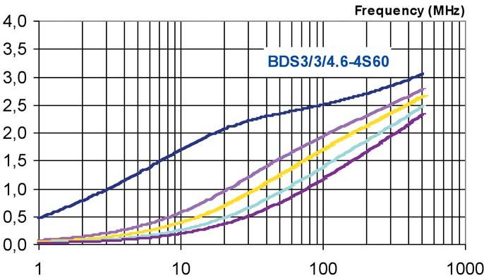
10 SMD Beads and Chokes Impedance Curves TYPICAL IMPEDANCE CURVES BDS3/1.8/5.3 Figure 9. Z graph BDS3/1.8/5.3-3S1 and BDS3/1.8/5.3-4S2 Figure 10. Z graph BDS3/3/4.6 in 3S1, 4S2, 3S5, 4S60 and 4S3 materials Figure 11. Z graph BDS3/3/8.9-3S1 and BDS3/3/8.9-4S2


11 SMD Beads and Chokes Impedance Curves Figure 12. Impedance vs. frequency for BDS3/1.8/5.3-3S1 under DC-premagnetization Figure 13. Impedance vs. frequency for BDS3/1.8/5.3-4S2 under DC-premagnetization Figure 14. Impedance vs. frequency for BDS3/3/4.6-3S1 under DC-premagnetization 11


12 SMD Beads Impedance Curves Figure 15. Impedance vs. frequency for BDS3/3/4.6-4S2 under DC-premagnetization BDS3/3/4.6-4S60 Figure 16. Impedance vs. frequency for BDS3/3/4.6-4S60 under DC-premagnetization BDS3/3/4.6-3S5 Figure 17. Impedance vs. frequency for BDS3/3/4.6-3S5 under DC-premagnetization


13 SMD Beads Impedance Curves BDS3/3/4.6-4S3 Figure 18. Impedance vs. frequency for BDS3/3/4.6-4S3 under DC-premagnetization Figure 19. Impedance vs. frequency for BDS3/3/8.9-3S1 under DC-premagnetization Figure 20. Impedance vs. frequency for BDS3/3/8.9-4S2 under DC-premagnetization 13

14 SMD Beads Impedance Curves Figure 21. Impedance vs. frequency for BDS4.6/3/8.9-4S2 under DC-premagnetization
 Figure 22.")
 Figure 23.")

15 SMD Beads Damping Curves TYPICAL DAMPING CURVES IL (db) Figure 22. Attenuation vs. frequency for BDS3/1.8/5.3-3S1 under DC-premagnetization IL (db) Figure 23. Attenuation vs. frequency for BDS3/1.8/5.3-4S2 under DC-premagnetization IL (db) Figure 24. Attenuation vs. frequency for BDS3/3/4.6-3S1 under DC-premagnetization 15

 Figure")
16 SMD Beads Damping Curves IL (db) Figure 25. Attenuation vs. frequency for BDS3/3/4.6-4S2 under DC-premagnetization IL (db) Figure 26. Attenuation vs. frequency for BDS3/3/4.6-4S60 under DC-premagnetization IL (db) Figure 27. Attenuation vs. frequency for BDS3/3/4.6-3S5 under DC-premagnetization


17 SMD Beads Damping Curves IL (db) Figure 28. Attenuation vs. frequency for BDS3/3/4.6-4S3 under DC-premagnetization IL (db) Figure 29. Attenuation vs. frequency for BDS3/3/8.9-3S1 under DC-premagnetization IL (db) Figure 30. Attenuation vs. frequency for BDS3/3/8.9-4S2 under DC-premagnetization 17

18 SMD Beads Damping Curves IL (db) Fig 31. Attenuation vs. frequency for BDS4.6/3/8.9-4S2 under DC-premagnetization

19 SMD Common Mode Chokes General, Product and Type Specification 5 OPERATING PRINCIPLE OF SMD COMMON MODE CHOKES Interference propagating via supply or signal lines can be suppressed by placing a high impedance in series. This can be provided by a ferrite inductor. However, saturation by the supply current can be a problem. Remedies are a low permeability material or a gapped / open magnetic circuit. The disadvantage is the large number of turns required to achieve the required inductance, leading to high copper losses. With standard suppression methods in a signal path, the wanted signal is often suppressed along with the interference, and in many modern applications (EDP for instance) this leads to unacceptable loss of signal. This can be overcome with current compensation, based on the fact that supply or signal currents in both lines are opposite and have equal magnitude. In Ferroxcube new interference-suppression beads, a pair of conductors within a single soft-ferrite block are connected along their lengths by an air gap. Common-mode signals - interference signals passing in the same direction along the input and output channels of a device (an IC for instance) - serve to reinforce the magnetic flux around both conductor, and are therefore attenuated. In contrast, the wanted signal passing along the input and output channel serves to cancel the flux around the conductors and therefore passes unattenuated. 5.1 PRODUCT APPLICATION These common mode chokes are available in 4 sizes in 4S2 material with 2 different winding configurations. In combination with appropriate tracks on the PCB the products can also serve as: Multi-Turn Choke Transformer The main application areas for the SMD common mode choke can be found in e.g.: Electronic data processing Telecommunication Consumer electronics Domestic appliances Figure 32. SMD Common Mode Choke 5.2 PRODUCT SPECIFICATON GENERAL SPECIFICATION FEATURES: Resistant to mechanical shocks and pressure High resistivity material Low tolerances of mechanical dimensions enable automatic mounting Flat sides to improve handling by automatic placement machines Low leakage inductance Suitable for different functions, depending on PCB connections APPLICATIONS: EMI suppression Supply line filtering Data line filtering TYPE DESCRIPTION: e.g. CMS2-5.6/3/4.8-4S2-Z (1) (2)(3)(4)(5) (6) (7) (1) Product type (CMS=Common Mode Surface mountable choke) (2) Number of strips (3) Width nominal (in mm) (4) Height maximum including wire (in mm) (5) Length nominal including wire (in mm) (6) Material grade (7) -Z lead-free version* *Note: Not lead-free old version available depending on stock.all new codes are leadfree (not -Z included on type description). ORDERING CODE (12 NC): e.g The first 11 digits of the 12 NC are sufficient to order the desired SMD commond mode choke. SMD common mode chokes are delivered taped and reeled, ready for use on automatic mounting machines. 19
20 SMD Common Mode Chokes General, Product and Type Specification SHAPE AND DIMENSIONS a-cms2-5.6/3/8.9 a-cms2-5.6/3/4.8 a-cms4-11/3/8.9 b-cms4-11/3/4.8 Figure 33. SMD common mode chokes dimensions (in millimeters) ELECTRICAL CHARACTERISTICS TYPE Remark IMPEDANCE [Ω] Mass AT FREQUENCY [MHz] (g) CMS2-5.6/3/4.8-4S ~ 0.3 CMS2-5.6/3/8.9-3S ~ 0.3 CMS2-5.6/3/8.9-4S ~ 0.3 CMS4-11/3/4.8-4S2 Inner channel Outer channel ~ 0.6 CMS4-11/3/8.9-4S2 Inner channel ~ 0.6 Outer channel Table 11. SMD common mode chokes electrical characteristics* *Note: Typical impedance values measured at 25ºC with Agilent-4191A impedance analyzer. Z min is -20% typical specified.
21 SMD Common Mode Chokes General, Product and Type Specification TYPE Maximum Vdc DC resistance Imax (A) Volts (mω) 25º 125º CMS2-5.6/3/4.8-4S2 60 < CMS2-5.6/3/8.9-3S4 60 < CMS2-5.6/3/8.9-4S2 60 < CMS4-11/3/4.8-4S2 60 < CMS4-11/3/8.9-4S2 60 < Table 12. SMD Common mode Choke electrical characteristics PACKAGING AND ORDERING CODES The SMD Common mode chokes are delivered taped and reeled, ready for use in automatic mounting machines. The packaging is according to IEC 286-A and EIA 481-A TYPE PACKING QUANTITY ORDERING CODE RoHS [PCS / REEL] [12 NC] CMS2-5.6/3/8.9-4S2-Z _ yes CMS2-5.6/3/8.9-3S4-Z _ yes CMS2-5.6/3/4.8-4S2-Z _ yes CMS4-11/3/4.8-4S2-Z _ yes CMS4-11/3/8.9-4S2-Z yes CMS2-5.6/3/8.9-4S _ no* CMS2-5.6/3/8.9-3S _ no* Table 13. SMD common mode chokes packaging quantities and ordering code * Check disponibility. Upon request BLISTER TAPE AND REEL DIMENSIONS SIZE DIMMENSIONS (mm) CMS2-5.6/3/4.8 CMS2-5.6/3/8.9 CMS4-11/3/4.8 CMS4-11/3/8.9 A B K T W E F D D1 > 1.5 > 1.5 > 1.5 > 1.5 P P P *Note: Figure 5 for reference detailed dimensions. Table 14. Physical dimensions of blister tape (in millimeters)* 21
* *Note: Figure 7 for reference detailed dimensions. 5.2.6 RECOMMENDED SOLDER LANDS Figure 34a. Solder lands for reflow soldering of CMS2-5.6/3/4.")
22 SMD Common Mode Chokes General, Product and Type Specification SIZE DIMENSIONS (mm) A N W1 W ± ± ± Table 15. Physical dimensions of reel (in millimeters)* *Note: Figure 7 for reference detailed dimensions RECOMMENDED SOLDER LANDS Figure 34a. Solder lands for reflow soldering of CMS2-5.6/3/4.8 Figure 34b. Solder lands for wave soldering of CMS2-5.6/3/4.8 Figure 34a. Figure 34b. Figure 35a. Solder lands for reflow soldering of CMS2-5.6/3/8.9 Figure 35b. Solder lands for wave soldering of CMS2-5.6/3/8.9 Figure 35a. Figure 35b. Figure 36a. Solder lands for reflow soldering of CMS4-11/3/4.8 Figure 36b. Solder lands for wave soldering of CMS4-11/3/4.8 Figure 36a. Figure 36b.
23 SMD Common Mode Chokes Impedance Curves TYPICAL IMPEDANCE CURVES CMS2-5.6/3/4.8-4S2 Figure 37. Z graph CMS2-5.6/3/4.8-4S2 (1 and 2 turns) CMS2-5.6/3/8.9-3S4 Figure 38. Z graph CMS2-5.6/3/4.8-3S4 (1 and 2 turns) CMS2-5.6/3/8.9-3S4 Figure 39. Z graph CMS2-5.6/3/8.9-3S4 (1 and 2 turns) 23


24 SMD Common Mode Chokes Impedance Curves Figure 40. Z graph CMS4-11/3/4.8-4S2 CMS4-11/3/8.9-4S2 Figure 41. Z graph CMS4-11/3/8.9-4S2

25 SMD Wide Band Chokes General, Product and Type Specification 6 OPERATING PRINCIPLE OF SMD WIDE BAND CHOKES SMD wide-band chokes are an alternative to a SMD bead when more impedance or damping is required.the design of this product is based on our well-known range of through-hole wide-band chokes. In these products the conductor wire is wound through holes in a multihole ferrite core, thus separating them physically and reducing coil capacitance. The result is a high impedance over a wide frequency range, a welcome feature for many interference problems. The present SMD design preserves the excellent properties and reliability of the original wide-band chokes by keeping the number of electrical interfaces to an absolute minimum. 6.1 PRODUCT APPLICATION SMD wide-band chokes are available in 3S4 and 4B1material with different winding configurations offering Z values according for each needed. As SMD beads and common mode chokes, the SMD wide-bands chokes are used in main electronics appliances: Electronic data processing Telecommunication Consumer electronics Domestic appliances 6.2 PRODUCT SPECIFICATON GENERAL SPECIFICATION FEATURES: Low leakage inductance due to closed magnetic circuit Small mechanical tolerances enable automatic mounting Flat sides to improve handling by automatic placement machines Reliability of simple design Single wire construction without extra electrical interfaces Resistant to mechanical shocks and pressure Resistant to thermal mismatch because of flexible wire connections APPLICATIONS: EMI suppression Damping of parasitic oscillations APPLICABLE MATERIALS: 3S4 covers medium frequencies up to 300 MHz 4B1 covers higher frequencies up to 1000 MHz TYPE DESCRIPTION: e.g.wbs2.5-5/4.8/10-4b1-z (1) (2) (3)(4) (5)(6) (7) (1) Product type (WBS=Wide Band choke for Surface mounting) (2) Number of turns (3) Width nominal (in mm) (4) Height maximum including wire (in mm) (5) Length nominal including wire (in mm) (6) Material grade (7) Lead-free version* *Note: Not lead-free old version available depending on stock.all new codes are leadfree (not -Z included on prime name) ORDERING CODE (12 NC): e.g The first 11 digits of the 12 NC are sufficient to order the desired SMD wide band choke. SMD wide band chokes are delivered taped and reeled, ready for use on automatic mounting machines. Figure 42. SMD wide-band chokes 25
26 SMD Wide Band Chokes General, Product and Type Description SHAPE AND DIMENSIONS Figure 43. SMD wide-band chokes dimensions (in millimeters)
27 SMD Wide Band Chokes General, Product and Type Description ELECTRICAL CHARACTERISTICS Table 16. SMD wide-band chokes electrical characteristics. TYPE IMPEDANCE [Ω] AT FREQUENCY [MHz] Mass (g) WBS1.5-5/4.8/10-3S ~ 0.9 WBS1.5-5/4.8/10-4B ~ 0.9 WBS2.5-5/4.8/10-3S ~ 0.9 WBS2.5-5/4.8/10-4B ~ 0.9 Table 17. SMD wide-band chokes electrical characteristics TYPE Maximum Vdc DC resistance Imax (A) Volts (mω) 25º 125º WBS1.5-5/4.8/10-3S4 60 < WBS1.5-5/4.8/10-4B1 60 < WBS2.5-5/4.8/10-3S4 60 < WBS2.5-5/4.8/10-4B1 60 < PACKAGING AND ORDERING CODES The SMD wide-band chokes are delivered taped and reeled, ready for use in automatic mounting machines. The packaging is according to IEC 286-A and EIA 481-A Table 18. SMD wide-band chokes packaging and ordering codes. TYPE PACKING QUANTITY ORDERING CODE [PCS / REEL] [12 NC] WBS1.5-5/4.8/10-4B _ WBS1.5-5/4.8/10-3S _ WBS1.5-5/10-3S4-Z _ WBS2.5-5/4.8/10-4B _ WBS2.5-5/10-4B1-Z _ WBS2.5-5/4.8/10-3S WBS2.5-5/10-3S4-Z _ WBSM2.5-5/4.8/10-4B _ 27

28 SMD Wide Band Chokes General, Product and Type Description BLISTER TAPE AND REEL DIMENSIONS Table 19. Physical dimensions of blister tape (in millimeters)* SIZE DIMENSIONS (mm) WBS1.5-5/4.8/10 WBS2.5-5/4.8/10 A B K T W E F D D P0 4 4 P1 8 8 P2 2 2 *Note: Figure 5 for reference detailed dimensions. Table 20. Physical dimensions of reel (in millimeters)* SIZE DIMENSIONS (mm) A N W1 W ± *Note: Figure 7 for reference detailed dimensions RECOMMENDED SOLDER LANDS Figure 44. Recommended solder lands for SMD wide-band chokes WBS1.5-5/4.8/10 and WBS2.5-5/4.8/10


29 SMD Wide Band Chokes Impedance Curves TYPICAL IMPEDANCE CURVES Figure 45. Z graph WBS1.5-5/4.8/10-3S4 and WBC1.5-5/4.8/10-4B1 Figure 46 Z graph WBS2.5-5/4.8/10-3S4 and WBC2.5-5/4.8/10-4B1 29


30 SMD Wide Band Chokes Impedance Curves Figure 47. Impedance vs. frequency for WBS1.5-5/4.8/10-3S4 under DC-premagnetization Figure 48. Impedance vs. frequency for WBS1.5-5/4.8/10-4S2 under DC-premagnetization Figure 49. Impedance vs. frequency for WBS2.5-5/4.8/10-3S4 under DC-premagnetization

31 SMD Wide Band Chokes Impedance Curves Figure 50. Impedance vs. frequency for WBS2.5-5/4.8/10-4S2 under DC-premagnetization 31
 Figure 51. Attenuation vs.")
 Figure 52.")
 Figure 53.")
32 SMD Wide Band Chokes Damping Curves TYPICAL DAMPING CURVES IL (db) Figure 51. Attenuation vs. frequency for WBS1.5-5/4.8/10-3S4 under DC-premagnetization IL (db) Figure 52. Attenuation vs. frequency for WBS1.5-5/4.8/10-4S2 under DC_premagnetization IL (db) Figure 53. Attenuation vs. frequency for WBS2.5-5/4.8/10-3S4 under DC_premagnetization

33 SMD Wide Band Chokes Damping Curves IL (db) Figure 54.Attenuation vs. frequency for WBS2.5-5/4.8/10-4S2 under DC _premagnetization 33

34 Gapped SMD Beads General, Product and Type Specification 7 GAPPED SMD BEADS FOR POWER INDUCTORS Traditional power supply architectures for PC s are facing problems with the latest generation of integrated circuits. Lower voltages and higher currents lead to increasing losses in supply lines and sensivity to interference. On top of this, fast microprocessors introduce high frequency transients which are difficult to regulate with a voltage regulator module (VRM) form a distant main supply. 7.1 PRODUCT APPLICATION The fundamental solution utilizes and intermediate voltage and distributed point of load (POL) converters. These are small dc/dc converters, placed close to the load on the PCB. Ferroxcube now introduces gapped SMD beads, perfectly suitable for the POL concept. They are small inductors typically meant to serve as output inductor in buck / boost stage and feature the state of the art power material 3C96. Depending on relative ripple current, switching frequencies up to 1 MHz are possible to realize compact geometries. Saturation rated current goes up to 20 A and the dc resistance is less than 1 m. These gapped beads are available in 2 sizes (1812 and 3512), packed in tape on reel, and they are SMD mountable. Furthermore, they are lead-free and fully comply with the RoHS regulations on hazardous substances. Our lowest loss general power material, 3C96 is an excellent choice to use in high-frequency output inductors. With a small ripple only, it can work at much higher switching frequency then it would as transformer material, preserving its highest higher saturation over real high-frequency transformer materials. 7.2 PRODUCT SPECIFICATON GENERAL SPECIFICATION FEATURES: Very suitable for POL converter concept High switching frequency, up to 1 MHz High current rating, up to 20 A Low dc resistance, less than 1 mω Small size (1812 and 3512 SMD mountable Lead-free / RoHs compliant SHAPE AND DIMENSIONS APPLICATIONS: Output inductor dc/dc converters EMI suppression with high current TYPE DESCRIPTION: e.g. BDS3/3/4.6-3C96-A75 (1)(2) (3) (4) (5) (6) (1) Product type (BDS = Bead for Surface mounting) (2) Width (in mm) (3) Height (in mm) (4) Length (in mm) (5) Material grade (6) AL inductor value ORDERING CODE (12 NC): e.g The first 11 digits of the 12 NC are sufficient to order the desired SMD wide band choke. SMD wide band chokes are delivered taped and reeled, ready for use on automatic mounting machines. Figure 56. Gapped SMD chip beads dimensions (in millimeters) Figure 55. Gapped SMD beads

35 Gapped SMD Beads General, Product and Type Specification ELECTRICAL CHARACTERISTICS TYPE AL Mass nh / t^2 (g) BDS3/3/4.6-3C96-A % ~ 0.15 BDS3/3/4.6-3C96-A % ~ 0.15 BDS4.6/3/8.9-A % ~ 0.15 BDS4.6/3/8.9-A % ~ 0.15 Table 21. Gapped SMD beads electrical characteristics Figure 57. Saturation Curves gapped SMD beads TYPE Maximum Vdc DC resistance Isat* Imax (A) Volts (mω) ma 25º 125º BDS3/3/4.6-3C96-A50 60 < BDS3/3/4.6-3C96-A75 60 < BDS4.6/3/8.9-A < BDS4.6/3/8.9-A < Table 22. Chip bead electrical characteristics* *Note: Isat is defined as the saturation rated current 35
36 Gapped SMD Beads General, Product and Type Specification PACKAGING AND ORDERING CODES The Capped SMD beads are delivered taped and reeled, ready for use in automatic mounting machines. The packaging is according to IEC 286-A and EIA 481-A TYPE PACKING QUANTITY ORDERING CODE [PCS / REEL] [12 NC] BDS3/3/4.6-3C96-A _ BDS3/3/4.6-3C96-A _ BDS4.6/3/8.9-A _ BDS4.6/3/8.9-A _ Table 23. Gapped SMD beads packaging quantities and ordering code BLISTER TAPE AND REEL DIMMENSIONS SIZE DIMENSIONS (mm) BDS3/3/4.6 BDS4.6/3/8.9 A ± ± 0.1 B0 5.1 ± ± 0.1 K0 3.1 ± ± 0.1 T 0.25 ± ± 05 W 12 ± ± 0.3 E 1.75 ± ± 0.1 F 5.5 ± ± 05 D D1 > 1.5 > 1.5 P0 4 ± ± 0.1 P1 8 ± ± 0.1 P2 2 ± 05 2 ± 0.1 Table 24. Physical dimensions of blister tape (in millimeters) *Note: Figure 5 for reference detailed dimensions. SIZE DIMENSIONS (mm) A N W1 W ± ± *Note: Figure 7 for reference detailed dimensions. Table 24. Physical dimensions of reel (in millimeters)
37 Gapped SMD Beads General, Product and Type Specification RECOMMENDED SOLDER LANDS Figure 58a. Solder lands reflow soldering Figure 58b. Solder lands wave soldering SHAPE Reflow soldering Wave soldering A B C D A B C D E BDS3/3/ BDS4.6/3/ Table 26. Dimensions (mm) of solder lands 37
38 SMD Beads and Chokes Soldering 8 SOLDERING CURVES Our surface mountable beads, common mode and wide-band chokes can be placed and soldered onto any normal printed circuit board or hybrid circuits. Suitable methods include those where the device is immersed in solder, wave soldering, reflow methods where the solder and device are heated together, and in vapor phase soldering. The robust construction of these SMD components enables them to be totally immersed in a solder bath at 255º up to 10 seconds for lead parts and up to 30 seconds at 260º for lead-free products without damage. This facilitates the mounting of leaded discrete components on the components side of a board after surface mountable beads or chokes have been attached to the side to be soldered, thus making a 'mixed print' board. Figure 59. Reflow soldering curve Typical temperature / time curves for different soldering methods are shown in next figures 59, 60, 61 for leaded products and 62 for lead-free parts. They show a preheating stage, followed by the soldering process at which the SMD components are fully subjected to the soldering temperature, and then finally cooling. Beads, common mode and wide-band chokes are able to withstand both the rapid rise in temperature, prior to soldering and the high temperature of the soldering process Figure 60.Wave soldering Figure 61.Vapor phase soldering
39 SMD Beads and Chokes Soldering Figure 62. Reflow soldering profile for lead-free types according to JEDEC STD. 39
40 SMD Beads and Chokes Maximun Current 9 MAXIMUM CURRENT LIMITS IN FUNCTION OF TEMPERATURE Next graphs shows maximum current that could be applied to Ferroxcube SMD parts and Rdc correspondat temperature variability: RDC (mohms) Imax (A) Figure 63. Imax. in function of temperature for SMD beads, common mode and wide band chokes. Figure 64. RDC in function of temperature for SMD beads, common mode and wide band chokes
MAGNETIC PRODUCTS. SMD Beads and Chokes
 MAGNETIC PRODUCTS SMD Beads and Chokes Philips Components Magnetic Products SMD beads in tape November 1994 2 Magnetic Products Philips Components Contents page SMD Beads 8 SMD Common Mode Chokes 14 SMD
application note Philips Magnetic Products Cable Shielding Philips Components
 application note Cable Shielding Philips Components Cable Shielding Contents Introduction 3 EMI suppression and cable shielding with ferrites 4 Ferrite selection 6 Material properties 7 Ferrite core and
FLTR100V10 Filter Module 75 Vdc Input Maximum, 10 A Maximum
 GE Critical Power FLTR100V10 Filter Module 75 Vdc Input Maximum, 10 A Maximum RoHS Compliant The FLTR100V10 Filter Module is designed to reduce the conducted common-mode and differential-mode noise on
FLTR100V20 Filter Module 75 Vdc Input Maximum, 20 A Maximum
 GE Critical Power FLTR100V20 Filter Module 75 Vdc Input Maximum, 20 A Maximum RoHS Compliant The FLTR100V20 Filter Module is designed to reduce the conducted common-mode and differential-mode noise on
FERROXCUBE DATA SHEET. SMD common mode chokes EMI-suppression products. Supersedes data of September Sep 01
 FERROXCUBE DATA SHEET Supersedes data of September 2004 2008 Sep 01 SMD COMMON MODE CHOKES FOR EMI-SUPPRESSION General data ITEM Strip material Solderability Taping method SPECIFICATION copper (Cu), tin
EMC Components. RF Chokes High Current B82432-H. Data Book Supplement
 EMC Components RF Chokes High Current B82432-H Data Book Supplement SIMID 03 (Siemens Miniature Inductors) Rated inductance 1,0 bis 330 µh Rated current 0,11 to 1,10 A Construction Size as per EIA standard:
Shielded Power Inductors
 Shielded Power Inductors MN509 Shielded inductor with minimum EMI Minimum power loss Non standard values available Low DC resistance Flat top for SMT operations Specifications Inductance tested at 100KHz
Ferroxcube Soft Ferrites (MnZn - NiZn) Company Introduction
 Company Introduction") Ferroxcube Soft Ferrites (MnZn - NiZn) Company Introduction Founder of Ferrite Cores 1941 E Core 5.3 to 100 Most common Very cheap Toroid 2.5 to 140 Best material properties Specialized winding E I Core
Ferroxcube Soft Ferrites (MnZn - NiZn) Company Introduction Founder of Ferrite Cores 1941 E Core 5.3 to 100 Most common Very cheap Toroid 2.5 to 140 Best material properties Specialized winding E I Core
FLTR75V05 Filter Module 75 Vdc Input Maximum, 5 A Maximum
 GE Critical Power FLTR75V05 Filter Module 75 Vdc Input Maximum, 5 A Maximum RoHS Compliant The FLTR75V05 Filter Module is designed to reduce the conducted common-mode and differentialmode noise on input
Solving Electromagnetic Interference (EMI) with Ferrites
 with Ferrites") Solving Electromagnetic Interference (EMI) with Ferrites What are ferrites? How do ferrites help Suppress EMI? How to chose proper ferrite and component Material Characteristics Material and Core Selection
Solving Electromagnetic Interference (EMI) with Ferrites What are ferrites? How do ferrites help Suppress EMI? How to chose proper ferrite and component Material Characteristics Material and Core Selection
Design Considerations
 Design Considerations Ferrite beads provide a simple, economical method for attenuating high frequency noise or oscillations. By slipping a bead over a wire, a RF choke or suppressor is produced which
INPAQ. Specification. WIP201610S L Series. Product Name. Power Inductor. Global RF/Component Solutions
 WIP201610S L Series Specification Product Name Series Power Inductor WIP201610S L Series Size EIAJ 2016 WIP201610S L Series Engineering Specification 1. Scope Feature High saturation current realized by
Ferrite EMI Noise Filtering
 Ferrite EMI Noise Filtering SOLUTIONS About Laird Technologies Laird Technologies is a global market leader in the design and supply of electromagnetic interference (EMI) shielding, thermal management
Vectron International Filter specification TFS 121 1/5
 Vectron International Filter specification TFS 121 1/ Measurement condition Ambient temperature: 23 Input power level: 0 dbm Terminating impedance: * Input: 130 Ω II 1,7 pf Output: 130 Ω II 1,7 pf Characteristics
SMT Inductors SIMID 1812-T B82432-T. Data Sheet
 SMT Inductors Data Sheet Size 1812 (EIA) or 4532 (IEC) Rated inductance 1,0 to 1000 µh Rated current 70 to 1300 ma Construction Upright ferrite drum core Laser-welded winding Flame-retardant encapsulation
VI TELEFILTER Filter Specification TFS 246 H4 1/5
 Filter Specification TFS 246 H4 1/5 Measurement condition Ambient temperature: 2 C Input power level: 0 dbm Terminating impedances *) Input: 490 Ω -2.62 pf Output: 490 Ω -2.62 pf External coil: 270 nh
Vectron International Filter specification TFS 243E 1/5
 Vectron International Filter specification TFS 243E /5 Measurement condition Ambient temperature T A: 23 C Input power level: 0 dbm Terminating impedance: * Input: 350 Ω -3.8 pf Output: 350 Ω -3.8 pf Characteristics
Vectron International Filter specification TFS 600 1/5
 Vectron International Filter specification TFS 600 /5 Measurement condition Ambient temperature: 23 C Input power level: 0 dbm Terminating impedance: * Input: 270 Ω -0,8 pf Output: 285 Ω -0,8 pf Characteristics
Tfs248e.doc version VI TELEFILTER Filter specification TFS 248 E 1/5. D a t a typ. Value Limit
 Filter specification TFS 248 E 1/5 Measurement condition Ambient temperature: 23 C Input power level: 0 dbm Terminating impedances at f c *) Input: 560 Ω -5.9pF Characteristics Output: 500 Ω -6.3 pf Remark:
(TREC) Wire Wound RF Chip Inductor
 Wire Wound RF Chip Inductor") Version: February 21, 2017 (TREC) Wire Wound RF Chip Inductor Token Electronics Industry Co., Ltd. Web: www.token.com.tw Email: rfq@token.com.tw Taiwan: No.137, Sec. 1, Zhongxing Rd., Wugu District, New
Version: February 21, 2017 (TREC) Wire Wound RF Chip Inductor Token Electronics Industry Co., Ltd. Web: www.token.com.tw Email: rfq@token.com.tw Taiwan: No.137, Sec. 1, Zhongxing Rd., Wugu District, New
CMC 14 Common Mode Chokes Series
 7 Electrical Data ID Code Inductance Value at C (-/+%) Less than % performance variations versus temperature (- C / + C) Minimum impedance attenuation : Ω from khz to MHz Compact SMD package (x pins) Applied
ELECTRICAL FILTERS. (Command Control Communications Computer & Intelligence) E 3 LINE FILTERS EMI LEMP NEMP HEMP TEMPEST
 E 3 LINE FILTERS EMI LEMP NEMP HEMP TEMPEST") ELECTRICAL FILTERS INTEGRATED PROTECTION OF C 4 I EQUIPMENT & FACILITIES (Command Control Communications Computer & Intelligence) E 3 LINE FILTERS EMI LEMP NEMP HEMP TEMPEST Electromagnetic Environmental
ELECTRICAL FILTERS INTEGRATED PROTECTION OF C 4 I EQUIPMENT & FACILITIES (Command Control Communications Computer & Intelligence) E 3 LINE FILTERS EMI LEMP NEMP HEMP TEMPEST Electromagnetic Environmental
Vectron International Filter specification TFS /5
 Vectron International Filter specification TFS 2533 1/5 Measurement condition Ambient temperature: 23 C Input power level: dbm Terminating impedance: * Input: 27,22 Ω -,32 pf Output: 27,22 Ω -,32 pf Source:
Kun Shan MAZO tech Co., Ltd
 Page : 1 / 1 High Current, Power Inductors MPCA-63-XXX-M Power Choke Description Halogen Free 125 C maximum total temperature operation 7.3x6.8x 3.mm maximum surface mount package Powder iron core material
SMD High Frequency Power Inductor. Designed for VRD & VRM 10.x & 11.x Applications
 Designed for VRD & VRM 1.x & 11.x Applications FEATURES Recommended for use with all major Voltage Regulator ICs High Current handling capability in the smallest footprint Up to 2MHz operating frequency
Vectron International Filter specification TFS1220 1/5
 Vectron International Filter specification TFS1220 1/5 Measurement condition Ambient temperature: 23 C Input power level: 0 dbm Terminating impedance: * Input: 146 Ω -0.9 pf Output: 146 Ω -0.9 pf Characteristics
SMD Common Mode Choke CUWI Series. CUWI Series For HDMI, USB 3.0. Product Identification
 CUWI Series For HDMI, USB 3.0 A full series of common mode choke is designed for excellent noise attenuation and compact sizing for use in wide range of applications. Both standard series and custom designs
Employing Reliable Protection Methods for Automotive Electronics
 Employing Reliable Protection Methods for Automotive Electronics WHITE PAPER BACKGROUND Automotive systems continue to become more sophisticated with the introduction of new, modified and improved features
Vectron International Filter specification TFS 1575AA 1/5
 Vectron International Filter specification TFS 1575AA 1/5 Measurement condition Ambient temperature: 23 C Input power level: 0 dbm Terminating impedance: Input: 50 Ω Output: 50 Ω Characteristics Remark:
Vectron International Filter specification TFS1590 1/5
 Vectron International Filter specification TFS1590 1/5 Measurement condition Ambient temperature T A: 23 C Input power level: 0 dbm Terminating impedance: Input: 50 Ω Output: 50 Ω Characteristics Remark:
YAGEO CORPORATION SMD INDUCTOR / BEADS. Notebook computers, step-up and step-down converters. Flash memory programmers, etc...
 YAGEO CORPORATION SMD INDUCTOR / BEADS SMD Power Inductors SDS0402 Series These shielded ultra-miniature inductors can help designers achieving significantly longer battery life in handheld communication
VI TELEFILTER Filter specification TFS 248F 1/5
 VI TELEFILTER Filter specification TFS 248F 1/5 Measurement condition Ambient temperature: 23 C Input power level: 0 dbm Terminating impedance: Input: 50 Ω Output: 200 Ω Characteristics Remark: The reference
Chip Inductor INTRODUCTION FEATURE AND APPLICATION. Feature. Application
 INTRODUCTION Multilayer Chip Inductor is an electronic part that uses in resonance circuit, for noise suppression and for impedance matching in the electrical circuit. SAMSUNG Electro-mechanics has 2 series
 Distributed by: www.jameco.com 1-800-831-4242 The content and copyrights of the attached material are the property of its owner. Data Sheet FLTR100V10 Filter Module RoHS Compliant Features Compatible with
VI TELEFILTER Filter specification TFS 915D 1/5
 Filter specification TFS 915D 1/5 Measurement condition Ambient temperature: 23 C Input power level: 0 dbm Terminating impedance: Input: 50 Ω Output: 50 Ω Characteristics Remark: The maximum attenuation
TRAFTOR WINDINGS CHANGING THE RULES TOROIDAL INDUCTORS & TRANSFORMERS SOLUTIONS PROVIDER AND MANUFACTURER
 TRAFTOR WINDINGS CHANGING THE RULES TOROIDAL INDUCTORS & TRANSFORMERS SOLUTIONS PROVIDER AND MANUFACTURER PRODUCT RANGE POWER INDUCTORS Toroidal technology, driven by 20 years of R&D. POWER TRANSFORMERS
Vectron International Filter specification TFS 868P 1/5
 Vectron International Filter specification TFS 868P 1/5 Measurement condition Ambient temperature: 23 C Input power level: 0 dbm Terminating impedance: * Input: 80 Ω -1.7 pf Output: 80 Ω -1.7 pf Characteristics
(TRMB) Multilayer Bead RF Inductors. Token Electronics Industry Co., Ltd. Version: January 13, Web:
 Multilayer Bead RF Inductors. Token Electronics Industry Co., Ltd. Version: January 13, Web:") Version: January 13, 2017 (TRMB) Multilayer Bead RF Inductors Token Electronics Industry Co., Ltd. Web: www.token.com.tw Email: rfq@token.com.tw Taiwan: No.137, Sec. 1, Zhongxing Rd., Wugu District, New
Version: January 13, 2017 (TRMB) Multilayer Bead RF Inductors Token Electronics Industry Co., Ltd. Web: www.token.com.tw Email: rfq@token.com.tw Taiwan: No.137, Sec. 1, Zhongxing Rd., Wugu District, New
Vectron International Filter specification TFS 737 1/5
 Vectron International Filter specification TFS 737 1/5 Measurement condition Ambient temperature: 23 C Input power level: 0 dbm Terminating impedance: Input: 50 Ω Output: 50 Ω Characteristics Remark: The
Vectron International Filter specification TFS 500 1/5
 Vectron International Filter specification TFS 500 1/5 Measurement condition Ambient temperature: 23 C Input power level: 0 dbm Terminating impedance: * Input: 415 Ω -1 pf Output: 415 Ω -1 pf External
Vectron International Filter specification TFS /5
 Vectron International Filter specification TFS 2653 1/5 Measurement condition Ambient temperature: 23 C Input power level: 0 dbm Terminating impedance: * Input: 27,66 Ω -0,01 pf Output: 27,66 Ω -0,01 pf
Vectron International Filter specification TFS 867A 1/5
 Vectron International Filter specification TFS 867A 1/5 Measurement condition Ambient temperature: 23 C Input power level: 0 dbm Terminating impedance: Input: 50 Ω Output: 50 Ω Characteristics Remark:
Vectron International Filter specification TFS 400P 1/5
 Vectron International Filter specification TFS 400P /5 Measurement condition Ambient temperature: 23 C Input power level: 0 dbm Terminating impedance: * Input: 280 Ω -6, pf Output: 440 Ω -5,2 pf Characteristics
RF Inductor Series. Token Electronics Industry Co., Ltd. Version: February 24, Web:
 Version: February 24, 2017 RF Inductor Series Web: www.token.com.tw Email: rfq@token.com.tw Token Electronics Industry Co., Ltd. Taiwan: No.137, Sec. 1, Zhongxing Rd., Wugu District, New Taipei City, Taiwan,
Kun Shan MAZO tech Co., Ltd
 Page : 1 / 8 High Current, Power Inductors MPCA-412-XXX-M Power Choke Description Halogen Free 125 C maximum total temperature operation 4.75 x 4.45 x 1.2mm maximum surface mount package Powder iron core
EMI/EMC Components - Data Line Filters
 The World s Most Advanced Passive Components EMI/EMC Components - Data Line Filters NZ Series Solid Chip Noise Suppressors (N608Z ~ N70Z) Multi-layered Chip Impedance Array Three-Terminal EMI Chip Filters
Vectron International Filter specification TFS140AV 1/5
 Vectron International Filter specification TFS140AV 1/5 Measurement condition Ambient temperature T A: 23 C Input power level: 0 dbm Terminating impedance: * Input: 50 Ω -78 pf Output: 95 Ω -52 pf Characteristics
DATA SHEET THIN-FILM CHIP RESISTORS TF 13 series, 0.1% TC25
 DATA SHEET THIN-FILM CHIP RESISTORS TF 13 series, 0.1% TC25 10 Ω TO 1 MΩ Product Specification Jul 10, 2003 V.3 FEATURES High precision High long-tem stability Low temperature coefficient. APPLICATIONS
Inductors for Power Circuits
 Inductors for Power Circuits Wound/STD magnetic shielded RLF series Type: RLF7030 (7.3x6.8 mm) RLF12545 (12.5x12.8 mm) RLF12560 (12.5x12.8 mm) Issue date: September 2011 (1/6) Inductors for Power Circuits
Vectron International Filter specification TFS /5
 Vectron International Filter specification TFS 1226 1/5 Measurement condition Ambient temperature: 23 C Input power level: 0 dbm Terminating impedance: * Input: 338 Ω -1.6 pf Output: 338 Ω -1.6 pf Characteristics
VI TELEFILTER Filter Specification TFS 211 C 1/5
 Filename: tfs211c.doc version 3.0 23.01.2002 Filter Specification TFS 211 C 1/5 Measurement condition Ambient temperature: 20... 25 C Input power level: 5 ± 2 dbm terminating impedances * Input: 1,1 kω
Vectron International Filter specification TFS 281 1/5
 Vectron International Filter specification TFS 281 1/5 Measurement condition Ambient temperature: 23 C Input power level: 0 dbm Terminating impedance: * Input: 183 Ω -12.5 pf Output: 172 Ω -12.6 pf Characteristics
Vectron International Filter specification TFS /5
 Vectron International Filter specification TFS 1960 1/5 Measurement condition Ambient temperature: 23 C Input power level: 0 dbm Terminating impedance: Input: 50 Ω Output: 50 Ω Characteristics Remark:
(TREM) High SRFs RF Inductor
 High SRFs RF Inductor") Version: March 1, 2017 Electronics Tech. (TREM) High SRFs RF Inductor Web: www.direct-token.com Email: rfq@direct-token.com Direct Electronics Industry Co., Ltd. China: 12F, Zhong Xing Industry Bld., Chuang
Version: March 1, 2017 Electronics Tech. (TREM) High SRFs RF Inductor Web: www.direct-token.com Email: rfq@direct-token.com Direct Electronics Industry Co., Ltd. China: 12F, Zhong Xing Industry Bld., Chuang
Kun Shan MAZO tech Co., Ltd
 Page : 1/9 High Current, Power Inductors LPCA-14-XXX-M Power Choke Description Halogen Free 125 C maximum total temperature operation 11.5x1.3x 4.mm maximum surface mount package Powder iron core material
Vectron International Filter specification TFS 400L 1/5
 Vectron International Filter specification TFS 400L 1/5 Measurement condition Ambient temperature: 23 C Input power level: 0 dbm Terminating impedance: Input: 200 Ω Output: 200 Ω Characteristics Remark:
Vectron International Filter specification TFS 1227A 1/5
 Vectron International Filter specification TFS 1227A 1/5 Measurement condition Ambient temperature: 23 C Input power level: 0 dbm Terminating impedance: Input: 50 Ω 0 pf Output: 50 Ω 0 pf Characteristics
SELECTION GUIDE. Nominal Input Voltage. Output Voltage
 MTE1 Series SELECTION GUIDE FEATURES Single isolated output 1kVDC Isolation Efficiency up to 88% Power density 1.8W/cm 3 Wide temperature performance at full 1 Watt load, 4 C to 85 C UL 94V- Package material
Vectron International Filter specification TFS 942G 1/5
 Vectron International Filter specification TFS 942G 1/5 Measurement condition Ambient temperature: 23 C Input power level: dbm Terminating impedance: Input: 5 Ω Output: 5 Ω Characteristics Remark: The
VI TELEFILTER Preliminary specification TFS 1575N 1/5
 VI TELEFILTER Preliminary specification TFS 1575N 1/5 Measurement condition Ambient temperature: 23 C Input power level: 0 dbm Terminating impedance: Input: 50 Ω Output: 50 Ω Characteristics Remark: The
Vectron International Filter specification TFS 1632A 1/5
 Vectron International Filter specification TFS 1632A 1/5 Measurement condition Ambient temperature: 23 C Input power level: 0 dbm Terminating impedance: * Input: 183 Ω -0,42 pf Output: 45 Ω -0,47 pf Characteristics
RF OUT / N/C RF IN / V G
 MAAM-111 MHz - 2 GHz Rev. V2 Features Functional Schematic 12 db Gain Ω Input / Output Match over Gain Range 3 db Gain Control with to -2 V Control +18 dbm Output Power + V, -. V DC, 7 ma Lead-Free 1.
Vectron International Filter specification TFS /5
 Vectron International Filter specification TFS 2096 1/5 Measurement condition Ambient temperature: 23 C Input power level: 0 dbm Terminating impedance: * Input: 200 Ω -0.38 pf Output: 75 Ω Characteristics
discontinued October 31, 2017 or until inventory is
 Supersedes June 2017 Applications Computer and portable power devices LCD panels, DVD players Inductor: DC-DC converters Buck, boost, forward, and resonant converters Noise filtering and filter chokes
Vectron International Filter specification TFS 125P 1/5
 Vectron International Filter specification TFS 125P 1/5 Measurement condition Ambient temperature: 23 C Input power level: 0 dbm Terminating impedance: * Input: 115 Ω -21 pf Output: 110 Ω -35 pf Characteristics
Vectron International Filter specification TFS180L 1/5
 Vectron International Filter specification TFS180L 1/5 Measurement condition Ambient temperature: 23 C Input power level: 0 dbm Terminating impedance: * Input: 205.51 Ω -23.24 pf Output: 141.63 Ω - 31.49
VI TELEFILTER Filter specification TFS /5
 VI TELEFILTER Filter specification TFS 2100 1/5 Measurement condition Ambient temperature: 23 C Input power level: 0 dbm Terminating impedance: Input: 50 Ω Output: 50 Ω Characteristics Remark: The maximum
(TRMA) Multilayer Ferrite Beads Chip Inductors. Token Electronics Industry Co., Ltd. Version: January 13, Web:
 Multilayer Ferrite Beads Chip Inductors. Token Electronics Industry Co., Ltd. Version: January 13, Web:") Version: January 13, 2017 (TRMA) Multilayer Ferrite Beads Chip Inductors Token Electronics Industry Co., Ltd. Web: www.token.com.tw Email: rfq@token.com.tw Taiwan: No.137, Sec. 1, Zhongxing Rd., Wugu District,
Version: January 13, 2017 (TRMA) Multilayer Ferrite Beads Chip Inductors Token Electronics Industry Co., Ltd. Web: www.token.com.tw Email: rfq@token.com.tw Taiwan: No.137, Sec. 1, Zhongxing Rd., Wugu District,
Vectron International Filter specification TFS1575AG 1/5
 Vectron International Filter specification TFS1575AG 1/5 Measurement condition Ambient temperature T A: 23 C Input power level: dbm Terminating impedance: Input: 5 Ω Output: 5 Ω Characteristics Remark:
Ferrites for High Frequency Noise Suppression Chapter 9
 TMPST ngineering and Hardware Design Dr. Bruce C. abrielson, NC 1998 Ferrites for High Frequency Noise Suppression Chapter 9 Introduction The drive for higher speed devices and the proliferation of widespread
NXF1 Series Isolated 1W Regulated Single Output DC-DC Converters
 www.murata-ps.com NXF1 Series SELECTION GUIDE FEATURES UL69 recognition pending Output regulation
VI TELEFILTER Filter specification TFS 130C 1/5
 VI TELEFILTER Filter specification TFS 130C 1/5 Measurement condition Ambient temperature: 23 C Input power level: 0 dbm Terminating impedance: * Input: 130 Ω -11.6 pf Output: 86 Ω -11.8 pf Characteristics
Switch Mode Power Supplies and their Magnetics
 Switch Mode Power Supplies and their Magnetics Many factors must be considered by designers when choosing the magnetic components required in today s electronic power supplies In today s day and age the
Vectron International Filter specification TFS1255A 1/5
 Vectron International Filter specification TFS1255A 1/5 Measurement condition Ambient temperature T A: 23 C Input power level: m Terminating impedance: Input: 5 Ω Output: 5 Ω Characteristics Remark: The
Vectron International Resonator Specification TFR 832 1/5
 Vectron International Resonator Specification TFR 832 1/5 Measurement condition Ambient temperature: 25 C Input power level: 0 dbm Terminating impedance: Input: 50 Ω Output: 50 Ω Characteristics Remark:
Electromagnetic Compatibility
 Electromagnetic Compatibility Introduction to EMC International Standards Measurement Setups Emissions Applications for Switch-Mode Power Supplies Filters 1 What is EMC? A system is electromagnetic compatible
Type 167/184 Metallized Polyester Radial Lead Capacitors Radial Box Metallized Polyester Capacitors for Automatic Insertion
 Radial Box Metallized Polyester Capacitors for Automatic Insertion Specifications Capacitance Range: Voltage Range: Capacitance Tolerance: Operating Temperature Range: Dielectric Withstand Voltage: Dissipation
Vectron International Filter specification TFS 522 1/5
 Vectron International Filter specification TFS 522 1/5 Measurement condition Ambient temperature (T 0): 23 C Input power level: 0 dbm Terminating impedance: Input: 50 Ω Output: 50 Ω Characteristics Remark:
VI TELEFILTER Filter specification TFS 70Z 1/5
 VI TELEFILTER Filter specification TFS 70Z /5 Measurement condition Ambient temperature: 23 C Input power level: 0 dbm Terminating impedance: * Input: 850 Ω -4,5 pf Output: 490 Ω -4, pf Characteristics
November Inductors for power circuits. Wound metal. SPM series. SPM10040 type SPM10040
 I N D U C T O R S November 2017 Inductors for power circuits Wound metal SPM series SPM10040 (2/9) REMINDERS FOR USING THESE PRODUCTS Before using these products, be sure to request the delivery specifications.
January Inductors for power circuits. Wound metal. SPM-HZ series (for automotive) SPM6530-HZ type SPM6530-HZ
 SPM6530-HZ type SPM6530-HZ") I N D U C T O R S January 2018 Inductors for power circuits Wound metal SPM-HZ series (for automotive) SPM6530-HZ (2/9) REMINDERS FOR USING THESE PRODUCTS Before using these products, be sure to request
I N D U C T O R S January 2018 Inductors for power circuits Wound metal SPM-HZ series (for automotive) SPM6530-HZ (2/9) REMINDERS FOR USING THESE PRODUCTS Before using these products, be sure to request
Vectron International Filter specification TFS246R 1/5
 Vectron International Filter specification TFS26R 1/5 Measurement condition Ambient temperature: 23 C Input power level: 0 dbm Terminating impedances*): input: 695 Ω -1.9 pf output: 695 Ω -1.9 pf Characteristics
EUA2011A. Low EMI, Ultra-Low Distortion, 2.5-W Mono Filterless Class-D Audio Power Amplifier DESCRIPTION FEATURES APPLICATIONS
 Low EMI, Ultra-Low Distortion, 2.5-W Mono Filterless Class-D Audio Power Amplifier DESCRIPTION The EUA2011A is a high efficiency, 2.5W mono class-d audio power amplifier. A new developed filterless PWM
February Inductors for power circuits. Wound metal. SPM series. SPM5030 type SPM5030
 I N D U C T O R S February 2018 Inductors for power circuits Wound metal SPM series SPM5030 (2/9) REMINDERS FOR USING THESE PRODUCTS Before using these products, be sure to request the delivery specifications.
Vectron International Filter specification TFS /5
 Vectron International Filter specification TFS 1575 1/5 Measurement condition Ambient temperature: 23 C Input power level: dbm Terminating impedance: Input: 5 Ω Output: 5 Ω Characteristics Remark: The
May Inductors for Power Circuits. Wound Metal. SPM Series. SPM6530 Type SPM6530
 I N D U C T O R S May 2017 Inductors for Power Circuits Wound Metal SPM Series SPM6530 (2/9) REMINDERS FOR USING THESE PRODUCTS Before using these products, be sure to request the delivery specifications.
Understanding and Optimizing Electromagnetic Compatibility in Switchmode Power Supplies
 Understanding and Optimizing Electromagnetic Compatibility in Switchmode Power Supplies 1 Definitions EMI = Electro Magnetic Interference EMC = Electro Magnetic Compatibility (No EMI) Three Components
Top View (Near-side) Side View Bottom View (Far-side) .89±.08. 4x.280. Orientation Marker Orientation Marker.
 Side View Bottom View (Far-side) .89±.08. 4x.280. Orientation Marker Orientation Marker.") Model B2F2AHF Ultra Low Profile 168 Balun Ω to 2Ω Balanced Description The B2F2AHF is a low profile sub-miniature balanced to unbalanced transformer designed for differential input locations on data conversion
Model B2F2AHF Ultra Low Profile 168 Balun Ω to 2Ω Balanced Description The B2F2AHF is a low profile sub-miniature balanced to unbalanced transformer designed for differential input locations on data conversion
Vectron International Filter specification TFS /5
 Vectron International Filter specification TFS 1795 1/5 Measurement condition Ambient temperature: 2 C Input power level: dbm Terminating impedance: Input: 5 Ω Output: 5 Ω Characteristics Remark: The maximum
MTE1 Series Isolated 1W Single Output SM DC/DC Converters
 MTE1 Series SELECTION GUIDE FEATURES Single isolated output 1kVDC Isolation Hi Pot Test Typical efficiency 86% Wide temperature performance at full 1 Watt load, 4 C to 85 C UL 69 recognised 3.3V, 5V, 12V,
Multilayer Ferrite Chip Inductor
 FEATURES Skywell multiplayer chip inductor is formed without a wound wire and has a closed magnetic circuit formed by simultaneous forming of alternative layers of ferrite paste and conductor paste. High
VI TELEFILTER Filter specification TFS /5
 VI TELEFILTER Filter specification TFS 1227 1/5 Measurement condition Ambient temperature: 23 C Input power level: dbm Terminating impedance: Input: 5 Ω Output: 5 Ω Characteristics Remark: The maximum
GLOSSARY OF TERMS FLUX DENSITY:
 ADSL: Asymmetrical Digital Subscriber Line. Technology used to transmit/receive data and audio using the pair copper telephone lines with speed up to 8 Mbps. AMBIENT TEMPERATURE: The temperature surrounding
Polypropylene Pulse/High Frequency Capacitors R79 Series Single Metallized Polypropylene Film, Radial, 5 mm Lead Spacing, Multipurpose Applications
 Polypropylene Pulse/High Frequency Capacitors R79 Series Single Metallized Polypropylene Film, Radial, 5 mm Lead Spacing, Multipurpose Applications Overview The R79 Series is constructed of metallized
MICRO INDUCTORS. Features. Applications. Ordering Information. Shape and Dimensions MI - I J J T (1) (2) (3) (4) (5) (6) (7)
 (2) (3) (4) (5) (6) (7)") MICRO INDUCTORS Features 1. Very high Self-Resonant Frequencies 2. Ultra miniature size and light(0.6mm mm mm). No polarity 4. Terminal electrode has excellent solder heat resistance for soldering. 5.
MICRO INDUCTORS Features 1. Very high Self-Resonant Frequencies 2. Ultra miniature size and light(0.6mm mm mm). No polarity 4. Terminal electrode has excellent solder heat resistance for soldering. 5.
August Inductors for power circuits. Wound metal. SPM-LR series. SPM5015-LR type SPM5015-LR
 I N D U C T O R S August 2017 Inductors for power circuits Wound metal SPM-LR series SPM5015-LR (2/9) REMINDERS FOR USING THESE PRODUCTS Before using these products, be sure to request the delivery specifications.
Vectron International Filter specification TFS455D 1/5
 Vectron International Filter specification TFS455D 1/5 Measurement condition Ambient temperature To: 23 C Input power level: dbm Terminating impedance: Input: 5 Ω Output: 5 Ω Characteristics Remark: The
North America Asia-Pacific Europe, Middle East
 Bel Power Solutions offers a complete range of input filters to help control EMI in board-level DC-DC converter applications. The table below lists combinations of input filters and DC-DC converters that
EMI AND BEL MAGNETIC ICM
 EMI AND BEL MAGNETIC ICM ABSTRACT Electromagnetic interference (EMI) in a local area network (LAN) system is a common problem that every LAN system designer faces, and it is a growing problem because the
Cal-Chip Electronics, Inc.
 Cal-Chip Electronics, Inc. Feature: These new SSL Series is designed for the smallest possible size, low cost and high performance. It's high energy storage and very low DC resistance offer higher saturated