LECTURE NOTES ELECTRONIC CIRCUITS II SYLLABUS
|
|
|
- Lauren Short
- 5 years ago
- Views:
Transcription
1 FATIMA MICHAEL COLLEGE OF ENGINEERING & TECHNOLOGY Madurai Sivagangai Main Road Madurai [An ISO 9001:2008 Certified Institution] LECTURE NOTES EC6401 ELECTRONIC CIRCUITS - II SEMESTER: IV / ECE Prepared by: T. SIVA KUMAR AP / ECE. SYLLABUS EC6401 ELECTRONIC CIRCUITS II LTPC OBJECTIVES: To understand the advantages and method of analysis of feedback amplifiers. To understand the analysis and design of LC and RC oscillators, amplifiers, multivibrators, and time base generators. UNIT I FEEDBACK AMPLIFIERS 9 General Feedback Structure Properties of negative feedback Basic Feedback Topologies Feedback amplifiers Series Shunt, Series Series, Shunt Shunt and Shunt Series Feedback Determining the Loop Gain Stability Problem Nyquist Plot Effect of feedback on amplifier poles Frequency Compensation. UNIT II OSCILLATORS 9 Classification, Barkhausen Criterion - Mechanism for start of oscillation and stabilization of amplitude, General form of an Oscillator, Analysis of LC oscillators - Hartley, Colpitts,Clapp, Franklin, Armstrong, Tuned collector oscillators, RC oscillators - phase shift Wienbridge - Twin-T Oscillators, Frequency range of RC and LC Oscillators, Quartz Crystal Construction, Electrical equivalent circuit of Crystal, Miller and Pierce Crystal oscillators, frequency stability of oscillators. UNIT III TUNED AMPLIFIERS 9 Coil losses, unloaded and loaded Q of tank circuits, small signal tuned amplifiers - Analysis of capacitor coupled single tuned amplifier double tuned amplifier - effect of cascading single tuned and double tuned amplifiers on bandwidth Stagger tuned amplifiers large signal tuned amplifiers Class C tuned amplifier Efficiency and applications of Class C tuned amplifier - Stability of tuned amplifiers Neutralization - Hazeltine neutralization method. UNIT IV WAVE SHAPING AND MULTIVIBRATOR CIRCUITS 9 RC & RL Integrator and Differentiator circuits Storage, Delay and Calculation of Transistor Switching Times Speed-up Capaitor - Diode clippers, Diode comparator - Clampers. Collector coupled and Emitter coupled Astable multivibrator Monostable multivibrator - Bistable multivibrators - Triggering methods for Bigtable multivibrators - Schmitt trigger circuit UNIT V BLOCKING OSCILLATORS AND TIMEBASE GENERATORS 9 UJT saw tooth waveform generator, Pulse transformers equivalent circuit response - applications, Blocking Oscillator Free running blocking oscillator - Astable Blocking Oscillators with base timing Push-pull Astable blocking oscillator with emitter timing, Frequency control using core saturation, Triggered blocking oscillator Monostable blocking oscillator with base timing Monostable blocking oscillator with emitter timing, Time base circuits - Voltage-Time base circuit, Current-Time base circuit Linearization through adjustment of driving waveform. TOTAL: 45 PERIODS TEXT BOOK: 1. Sedra and Smith, Micro Electronic Circuits ; Sixth Edition, Oxford University Press, REFERENCES: 1. Robert L. Boylestad and Louis Nasheresky, Electronic Devices and Circuit Theory, 10 th Edition,


2 Pearson Education / PHI, David A. Bell, Electronic Devices and Circuits, Fifth Edition, Oxford University Press, Millman J. and Taub H., Pulse Digital and Switching Waveforms, TMH, Millman and Halkias. C., Integrated Electronics, TMH, 2007.

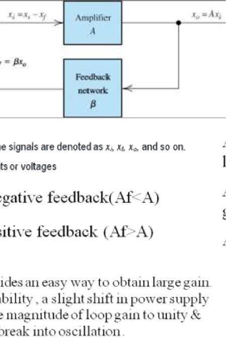
3 Block diagram


4
5


6

7

8

9


10


11

12

13
14

15


16

17

18
19

20

21
22
23
24

25
26


27 UJT A Unijunction transistor is a three terminal semiconductor switching device.this device has a unique characteristics that when it is triggered, the emitter current increases regeneratively until is limited by emitter power supply the unijunction transistor can be employed in a variety of applications switching pulse generator saw tooth generator etc. Construction

28 It consists of an N type silicon bar with an electrical connection on each end the leads to these connection are called base leads. Base 1 B1 Base 2 B2 the bar between the two bases nearer to B2 than B1. A pn junction is formed between a p type emitter and Bar.the lead to the junction is called emitter lead E. Operation The device has normally B2 positive w.r.t B1 If voltage VBB is applied between B2 and B1 with emitter open. Voltage gradient is established along the n type bar since emitter is located nearer to B2 more than half of VBB appears between the emitter and B1. the voltage V1 between emitter and B1 establishes a reverse bias on the pn junction and the emitter current is cut off. A small leakage current flows from B2 to emitter due to minority carriers If a positive voltage is applied at the emitter the pn junction will remain reverse biased so long as the input voltage is less than V1 if the input voltage to the emitter exceeds V1 the pn junction becomes forward biased. under these conditions holes are injected from the p type material into the n type bar these holes are repelled by positive B2 terminal and they are attracted towards B1 terminal of the bar. This accumulation of holes in the emitter to B1 region results in the degrees of resistance in this section of the bar the internal voltage drop from emitter to b1 is decreased hence emitter current Ie increases as more holes are injected a condition of saturation will eventually be reached at this point a emitter current limited by emitter power supply only the devices is in on state. If a negative pulse is applied to the emitter, the pn junction is reverse biased and the emitter current is cut off. The device is said to be off state. Characteristics of UJT


29 The curve between Emitter voltage Ve and emitter current Ie of a UJT at a given voltage Vbb between the bases this is known as emitter characteristic of UJT Initially in the cut off region as Ve increases from zero,slight leakage current flows from terminal B2 to the emitter the current is due to the minority carriers in the reverse biased diode. Above a certain value of Ve forward Ie begins to flow, increasing until the peak voltage Vp and current Ip are reached at point P. After the peak point P an attempt to increase Ve is followed by a sudden increases in emitter current Ie with decrease in Ve is a negative resistance portion of the curve The negative portion of the curve lasts until the valley point V is reached with valley point voltage Vv.and valley point current Iv after the valley point the device is driven to saturation the difference Vp-Vv is a measure of a switching efficiency of UJT fall of Vbb decreases Advantages of UJT It is a Low cost device It has excellent characteristics It is a low-power absorbing device under normal operating conditions

30 TRANSFORMER EQUIVALENT CIRCUIT: The influences of a transformer s parameters can best be understood by considering the equivalent circuit in below. This circuit shows a typical output pulse waveform. Assuming that this output pulse is the result of injecting an ideal rectangular input pulse, one can see that a number of parameters are distorted. Overshoot, droop, back swing, rise time, etc. appear as unwanted signal distortion on the output pulse. Assuming the pulse transformer is properly matched and the source is delivering an ideal rectangular pulse, the transformer should have low values of leakage inductance and distributed capacitance while having a high open circuit inductance. This will limit the deterioration of the pulse shape. Also, the fact that the source will never produce an ideal rectangular pulse adds to the problems of distortion.

31
32
33
Sub Code & Name: EC2251- ELECTRONIC CIRCUITS II Unit : I Branch : ECE Year:II
 Unit : I Branch : ECE Year:II Page 01 of 06 UNIT 1 FEEDBACK AMPLIFIERS 9 Block diagram, Loop gain, Gain with feedback, Effects of negative feedback Sensitivity and desensitivity of gain, Cut-off frequencies,
Course File Leaf (Theory) For the Academic Year (Odd/Even Semester)
 For the Academic Year (Odd/Even Semester)") Nadar Saraswathi College of Engineering and Technology, Vadapudupatti, Theni - 625 531 (Approved by AICTE, New Delhi and Affiliated to Anna University, Chennai) Course File Leaf (Theory) For the Academic
Nadar Saraswathi College of Engineering and Technology, Vadapudupatti, Theni - 625 531 (Approved by AICTE, New Delhi and Affiliated to Anna University, Chennai) Course File Leaf (Theory) For the Academic
BHARATHIDASAN ENGINEERING COLLEGE
 BHARATHIDASAN ENGINEERING COLLEGE DEPARTMENT OF ELECTRONICS AND COMMUNICATION ENGINEERING EC6401 - ELECTRONIC CIRCUITS - II QUESTION BANK II- YEAR IV SEM ACDEMIC YEAR: 2016-2017 EVEN SEMESTER EC6401 ELECTRONIC
ELECTRONIC CIRCUITS - II BY A P GODSE, U A BAKSHI DOWNLOAD EBOOK : ELECTRONIC CIRCUITS - II BY A P GODSE, U A BAKSHI PDF
 Read Online and Download Ebook ELECTRONIC CIRCUITS - II BY A P GODSE, U A BAKSHI DOWNLOAD EBOOK : ELECTRONIC CIRCUITS - II BY A P GODSE, U A BAKSHI Click link bellow and free register to download ebook:
VALLIAMMAI ENGINEERING COLLEGE
 VALLIAMMAI ENGINEERING COLLEGE SRM Nagar, Kattankulathur 603 203. DEPARTMENT OF ELECTRONICS & COMMUNICATION ENGINEERING SUBJECT QUESTION BANK : EC6401 ELECTRONICS CIRCUITS-II SEM / YEAR: IV / II year B.E.
Question Bank EC6401 ELECTRONIC CIRCUITS - II
 FATIMA MICHAEL COLLEGE OF ENGINEERING & TECHNOLOGY Madurai Sivagangai Main Road Madurai - 625 020. [An ISO 9001:2008 Certified Institution] SEMESTER: IV / ECE Question Bank EC6401 ELECTRONIC CIRCUITS -
NOORUL ISLAM COLLEGE OF ENGG, KUMARACOIL. DEPARTMENT OF ELECTRONICS AND COMMUNICATION ENGG. SUBJECT CODE: EC 1251 SUBJECT NAME: ELECTRONIC CIRCUITS-II
 NOORUL ISLAM COLLEGE OF ENGG, KUMARACOIL. DEPARTMENT OF ELECTRONICS AND COMMUNICATION ENGG. SUBJECT CODE: EC 1251 SUBJECT NAME: ELECTRONIC CIRCUITS-II Prepared by, C.P.SREE BALA LEKSHMI (Lect/ECE) ELECTRONICS
Oscillators. Hartley, Colpitts, UJT relaxation. ECE/MEA Engg College S.R.K. 9/13/2007 Authored by: Ramesh.K
 Oscillators Hartley, Colpitts, UJT relaxation. S.R.K 9//007 Authored by: Ramesh.K This documents contains a brief note about the principle of sinusoidal oscillator and some general oscillator circuits
VALLIAMMAI ENGINEERING COLLEGE
 VALLIAMMAI ENGINEERING COLLEGE SRM Nagar, Kattankulathur 603 203 DEPARTMENT OF ELECTRONICS AND COMMUNICATION ENGINEERING QUESTION BANK IV SEMESTER EC6401 ELECTRONICS CIRCUITS-II Regulation 2013 Academic
EC202- ELECTRONIC CIRCUITS II Unit- I -FEEEDBACK AMPLIFIER
 EC202- ELECTRONIC CIRCUITS II Unit- I -FEEEDBACK AMPLIFIER 1. What is feedback? What are the types of feedback? 2. Define positive feedback. What are its merits and demerits? 3. Define negative feedback.
VETRI VINAYAHA COLLEGE OF ENGINEERING & TECHNOLOGY THOTTIAM, TIRUCHIRAPPALLI Department of Electronics and communication Engineering Question
 VETRI VINAYAHA COLLEGE OF ENGINEERING & TECHNOLOGY THOTTIAM, TIRUCHIRAPPALLI-621215 Department of Electronics and communication Engineering Question Bank EC6401: ELECTRONIC CIRCUITS II (Regulation 2013)
SCR- SILICON CONTROLLED RECTIFIER
 SCR- SILICON CONTROLLED RECTIFIER Definition: When a pn junction is added to a junction transistor, the resulting three pn junction device is called a silicon controlled rectifier. SCR can change alternating
Multivibrators. Department of Electrical & Electronics Engineering, Amrita School of Engineering
 Multivibrators Multivibrators Multivibrator is an electronic circuit that generates square, rectangular, pulse waveforms. Also called as nonlinear oscillators or function generators. Multivibrator is basically
Basic Electronics Learning by doing Prof. T.S. Natarajan Department of Physics Indian Institute of Technology, Madras
 Basic Electronics Learning by doing Prof. T.S. Natarajan Department of Physics Indian Institute of Technology, Madras Lecture 38 Unit junction Transistor (UJT) (Characteristics, UJT Relaxation oscillator,
State the application of negative feedback and positive feedback (one in each case)
") (ISO/IEC - 700-005 Certified) Subject Code: 073 Model wer Page No: / N Important Instructions to examiners: ) The answers should be examined by key words and not as word-to-word as given in the model answer
(ISO/IEC - 700-005 Certified) Subject Code: 073 Model wer Page No: / N Important Instructions to examiners: ) The answers should be examined by key words and not as word-to-word as given in the model answer
MARIA COLLEGE OF ENGINEERING AND TECHNOLOGY, ATTOOR UNIT-1. Feedback Amplifiers
 MARIA COLLEGE OF ENGINEERING AND TECHNOLOGY, ATTOOR DEPARTMENT OF ELECTRONICS AND COMMUNICATION ENGINEERING ELECTRONIC CIRCUITS-II 2 MARKS QUESTIONS & ANSWERS UNIT-1 Feedback Amplifiers 1. What is meant
APPLIED ELECTRONIC CIRCUITS
 SRM UNIVERSITY DEPARTMENT OF BIOMEDICAL ENGINEERING ODD Semester-2014-2015 BM1005 APPLIED ELECTRONIC CIRCUITS Course Code: BM1005 Course Title: APPLIED ELECTRONIC CIRCUITS Sem: III SEM B. Tech Second Year
Lab 4 : Transistor Oscillators
 Objective: Lab 4 : Transistor Oscillators In this lab, you will learn how to design and implement a colpitts oscillator. In part II you will implement a RC phase shift oscillator Hardware Required : Pre
DEPT. OF ELECTRICAL & ELECTRONICS ENGG SRM INSTITUTE OF SCIENCE & TECHNOLOGY LESSON PLAN. Subject Name : Electronic Circuits
 DEPT. OF ELECTRICAL & ELECTRONICS ENGG SRM INSTITUTE OF SCIENCE & TECHNOLOGY LESSON PLAN Subject Code : EE0208 Subject Name : Electronic Circuits Branch : ELECTRICAL AND ELECTRONICS Year : II Section C
MAHALAKSHMI ENGINEERING COLLEGE TIRUCHIRAPALLI UNIT V BLOCKING OSCILLATORS AND TIME BASE GENERATORS
 MAHALAKSHMI ENGINEERING COLLEGE TIRUCHIRAPALLI-621213. UNIT V BLOCKING OSCILLATORS AND TIME BASE GENERATORS PART A (2 Marks) 1. What is blocking oscillator? The circuit which uses a regenerative feedback,
Chapter.8: Oscillators
 Chapter.8: Oscillators Objectives: To understand The basic operation of an Oscillator the working of low frequency oscillators RC phase shift oscillator Wien bridge Oscillator the working of tuned oscillator
 11. What is fall time (tf) in transistor? The time required for the collector current to fall from 90% to 10% of its DEPARTMENT OF ECE EC 6401 Electronic Circuits II UNIT-IV WAVE SHAPING AND MULTIVIBRATOR
UNIT 1. 9 What is the Causes of Free Response in Electrical Circuit. 12 Write the Expression for transient current and voltages of RL circuit.
 SUB: Electric Circuits and Electron Devices Course Code: UBEE309 UNIT 1 PART A 1 State Transient and Transient Time? 2 What is Tansient State? 3 What is Steady State? 4 Define Source Free Response 5 Define
Government Polytechnic Muzaffarpur Name of the Lab: Applied Electronics Lab
 Government Polytechnic Muzaffarpur Name of the Lab: Applied Electronics Lab Subject Code: 1620408 Experiment-1 Aim: To obtain the characteristics of field effect transistor (FET). Theory: The Field Effect
UNIT 1 MULTI STAGE AMPLIFIES
 UNIT 1 MULTI STAGE AMPLIFIES 1. a) Derive the equation for the overall voltage gain of a multistage amplifier in terms of the individual voltage gains. b) what are the multi-stage amplifiers? 2. Describe
TUNED AMPLIFIERS. Tank circuits.
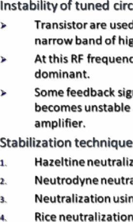
 Tank circuits. TUNED AMPLIFIERS Analysis of single tuned amplifier, Double tuned, stagger tuned amplifiers. Instability of tuned amplifiers, stabilization techniques, Narrow band neutralization using coil,
 VALLIAMMAI ENGINEERING COLLEGE SRM NAGAR, KATTANKULATHUR- 603 203 DEPARTMENT OF ELECTRONICS AND COMMUNICATION ENGINEERING EC6202- ELECTRONIC DEVICES AND CIRCUITS UNIT I PN JUNCTION DEVICES 1. Define Semiconductor.
UNIT I PN JUNCTION DEVICES
 UNIT I PN JUNCTION DEVICES 1. Define Semiconductor. 2. Classify Semiconductors. 3. Define Hole Current. 4. Define Knee voltage of a Diode. 5. What is Peak Inverse Voltage? 6. Define Depletion Region in
EC6202-ELECTRONIC DEVICES AND CIRCUITS YEAR/SEM: II/III UNIT 1 TWO MARKS. 1. Define diffusion current.
 EC6202-ELECTRONIC DEVICES AND CIRCUITS YEAR/SEM: II/III UNIT 1 TWO MARKS 1. Define diffusion current. A movement of charge carriers due to the concentration gradient in a semiconductor is called process
Microelectronic Circuits
 SECOND EDITION ISHBWHBI \ ' -' Microelectronic Circuits Adel S. Sedra University of Toronto Kenneth С Smith University of Toronto HOLT, RINEHART AND WINSTON HOLT, RINEHART AND WINSTON, INC. New York Chicago
DHANALAKSHMI COLLEGE OF ENGINEERING DEPARTMENT OF ELECTRICAL AND ELECTRONICS ENGINEERING EC6202 ELECTRONIC DEVICES AND CIRCUITS
 DHANALAKSHMI COLLEGE OF ENGINEERING DEPARTMENT OF ELECTRICAL AND ELECTRONICS ENGINEERING EC6202 ELECTRONIC DEVICES AND CIRCUITS UNIT-I - PN DIODEAND ITSAPPLICATIONS 1. What is depletion region in PN junction?
AE53/AC53/AT53/AE103 ELECT. DEVICES & CIRCUITS DEC 2015
 Q.2 a. By using Norton s theorem, find the current in the load resistor R L for the circuit shown in Fig.1. (8) Fig.1 IETE 1 b. Explain Z parameters and also draw an equivalent circuit of the Z parameter
PESIT - BANGALORE SOUTH CAMPUS PART A
 PESIT - BANGALORE SOUTH CAMPUS LESSON - PLAN FOR BASIC ELECTRONICS ENGG. Name of Faculty: Percentage of course Periods Reference/ Text books Topics covered Reference chapter covered Cumulative PART A Unit
B.Sc. Syllabus for Electronics under CBCS. Semester-I
 Semester-I Title: Electronic Circuit Analysis Course Code: UELTC101 Credits: 4 Total Marks: 100 Internal Examination: 20 marks End Semester Examination: 80 marks Duration: 3 hours Validity of Syllabus:
TUNED AMPLIFIERS 5.1 Introduction: Coil Losses:
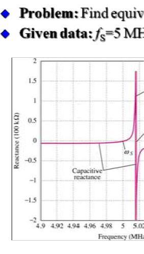
 TUNED AMPLIFIERS 5.1 Introduction: To amplify the selective range of frequencies, the resistive load R C is replaced by a tuned circuit. The tuned circuit is capable of amplifying a signal over a narrow
OBJECTIVE TYPE QUESTIONS
 OBJECTIVE TYPE QUESTIONS Q.1 The breakdown mechanism in a lightly doped p-n junction under reverse biased condition is called (A) avalanche breakdown. (B) zener breakdown. (C) breakdown by tunnelling.
Expect to be successful, expect to be liked,
 Thought of the Day Expect to be successful, expect to be liked, expect to be popular everywhere you go. Oscillators 1 Oscillators D.C. Kulshreshtha Oscillators 2 Need of an Oscillator An oscillator circuit
FREQUENTLY ASKED QUESTIONS
 FREQUENTLY ASKED QUESTIONS UNIT-1 SUBJECT : ELECTRONIC DEVICES AND CIRCUITS SUBJECT CODE : EC6202 BRANCH: EEE PART -A 1. What is meant by diffusion current in a semi conductor? (APR/MAY 2010, 2011, NOV/DEC
SKP Engineering College
 SKP Engineering College Tiruvannamalai 606611 A Course Material on Electronics Circuits-II M.Jerin Jose Associate Professor Electronics and Communication Engineering Department By Electronics and Communication
e base generators Tim 1
 Time base generators 1 LINEAR TIME BASE GENERATORS Circuits thatprovide An Output Waveform Which Exhibits Linear Variation Of Voltage or current With Time. Linear variation of Voltage :Voltage time base
Feedback and Oscillator Circuits
 Chapter 14 Chapter 14 Feedback and Oscillator Circuits Feedback Concepts The effects of negative feedback on an amplifier: Disadvantage Lower gain Advantages Higher input impedance More stable gain Improved
Solapur University, Solapur Syllabus for B.Sc. II Electronics Semester System To be implemented from Academic Year ) Course Structure: -
 Course Structure: -") 1 Solapur University, Solapur Syllabus for B.Sc. II Electronics Semester System To be implemented from Academic Year 2011-12 1) Course Structure: - Sr. Semester Paper Title Total No No. 1. Semester-III
1 Solapur University, Solapur Syllabus for B.Sc. II Electronics Semester System To be implemented from Academic Year 2011-12 1) Course Structure: - Sr. Semester Paper Title Total No No. 1. Semester-III
Sri venkateswara college of engineering. Department of ECE. EC Electronic Circuits II. 2 mark questions unit wise. UNIT I Feedback Amplifiers
 Sri venkateswara college of engineering Department of ECE EC -6401 Electronic Circuits II 2 mark questions unit wise UNIT I Feedback Amplifiers 1. Define feedback? A portion of the output signal is taken
EC8351-ELECTRON DEVICES AND CIRCUITS TWO MARK QUESTIONS AND ANSWERS UNIT-I PN JUNCTION DEVICES
 TWO MARK QUESTIONS AND ANSWERS UNIT-I PN JUNCTION DEVICES 1) Define semiconductor. Semiconductor is a substance, which has resistivity in between Conductors and insulators. Eg. Germanium, Silicon. 2) Define
MAHARASHTRA STATE BOARD OF TECHNICAL EDUCATION (Autonomous) (ISO/IEC Certified) Summer 2016 EXAMINATIONS.
 (ISO/IEC Certified) Summer 2016 EXAMINATIONS.") Summer 2016 EXAMINATIONS Subject Code: 17321 Model Answer Important Instructions to examiners: 1) The answers should be examined by key words and not as word-to-word as given in the answer scheme. 2) The
Summer 2016 EXAMINATIONS Subject Code: 17321 Model Answer Important Instructions to examiners: 1) The answers should be examined by key words and not as word-to-word as given in the answer scheme. 2) The
Lesson Plan. Electronics 1-Total 51 Hours
 Lesson Plan. Electronics 1-Total 5s Unit I: Electrical Engineering materials:(10) Crystal structure & defects; Ceramic materials-structures, composites, processing and uses; Insulating laminates for electronics,
Feedback Amplifier & Oscillators
 256 UNIT 5 Feedback Amplifier & Oscillators 5.1 Learning Objectives Study definations of positive /negative feedback. Study the camparions of positive and negative feedback. Study the block diagram and
Emitter base bias. Collector base bias Active Forward Reverse Saturation forward Forward Cut off Reverse Reverse Inverse Reverse Forward
 SEMICONDUCTOR PHYSICS-2 [Transistor, constructional characteristics, biasing of transistors, transistor configuration, transistor as an amplifier, transistor as a switch, transistor as an oscillator] Transistor
ECE 440 Lecture 29 : Introduction to the BJT-I Class Outline:
 ECE 440 Lecture 29 : Introduction to the BJT-I Class Outline: Narrow-Base Diode BJT Fundamentals BJT Amplification Things you should know when you leave Key Questions How does the narrow-base diode multiply
 SET - 1 1. a) Write the application of attenuator b) State the clamping theorem c) Write the application of Monostable multi vibrator d) Draw the diagram for Diode two input AND gate e) Define the terms
DEFINITION: Classification of oscillators Based on the frequency generated Oscillator type Frequency range
 DEFINITION: An oscillator is just an electronic circuit which converts dc energy into AC energy of required frequency. (Or) An oscillator is an electronic circuit which produces an ac output without any
LINEAR IC APPLICATIONS
 1 B.Tech III Year I Semester (R09) Regular & Supplementary Examinations December/January 2013/14 1 (a) Why is R e in an emitter-coupled differential amplifier replaced by a constant current source? (b)
Exam Booklet. Pulse Circuits
 Exam Booklet Pulse Circuits Pulse Circuits STUDY ASSIGNMENT This booklet contains two examinations for the six lessons entitled Pulse Circuits. The material is intended to provide the last training sought
SIDDHARTH GROUP OF INSTITUTIONS :: PUTTUR (AUTONOMOUS) Siddharth Nagar, Narayanavanam Road QUESTION BANK
 Siddharth Nagar, Narayanavanam Road QUESTION BANK") SIDDHARTH GROUP OF INSTITUTIONS :: PUTTUR (AUTONOMOUS) Siddharth Nagar, Narayanavanam Road 517583 QUESTION BANK Subject with Code : Electronic Circuit Analysis (16EC407) Year & Sem: II-B.Tech & II-Sem
SIDDHARTH GROUP OF INSTITUTIONS :: PUTTUR (AUTONOMOUS) Siddharth Nagar, Narayanavanam Road 517583 QUESTION BANK Subject with Code : Electronic Circuit Analysis (16EC407) Year & Sem: II-B.Tech & II-Sem
Oscillators. An oscillator may be described as a source of alternating voltage. It is different than amplifier.
 Oscillators An oscillator may be described as a source of alternating voltage. It is different than amplifier. An amplifier delivers an output signal whose waveform corresponds to the input signal but
Devices and Op-Amps p. 1 Introduction to Diodes p. 3 Introduction to Diodes p. 4 Inside the Diode p. 6 Three Diode Models p. 10 Computer Circuit
 Contents p. v Preface p. ix Devices and Op-Amps p. 1 Introduction to Diodes p. 3 Introduction to Diodes p. 4 Inside the Diode p. 6 Three Diode Models p. 10 Computer Circuit Analysis p. 16 MultiSIM Lab
Chapter 1 Semiconductors and the p-n Junction Diode 1
 Preface xiv Chapter 1 Semiconductors and the p-n Junction Diode 1 1-1 Semiconductors 2 1-2 Impure Semiconductors 5 1-3 Conduction Processes in Semiconductors 7 1-4 Thep-nJunction 9' 1-5 The Meta1-Semiconductor
Subject Code: Model Answer Page No: / N
 Important Instructions to examiners: 1) The answers should be examined by key words and not as word-to-word as given in the model answer scheme. 2) The model answer and the answer written by candidate
For reference, the readers can browse through our ELECTRONIC CIRCUITS tutorial at https://www.tutorialspoint.com/electronic_circuits/index.htm.
 About the Tutorial In this tutorial, we will discuss all the important circuits that are related to pulse signals. In addition, we will also cover the circuits that generate and work with pulse signals.
R a) Explain the operation of RC high-pass circuit when exponential input is applied.
 Explain the operation of RC high-pass circuit when exponential input is applied.") SET - 1 1. a) Explain the operation of RC high-pass circuit when exponential input is applied. 2x V ( e 1) V b) Verify V2 = = tanhx for a symmetrical square wave applied to a RC low 2x 2 ( e + 2 pass circuit.
SET - 1 1. a) Explain the operation of RC high-pass circuit when exponential input is applied. 2x V ( e 1) V b) Verify V2 = = tanhx for a symmetrical square wave applied to a RC low 2x 2 ( e + 2 pass circuit.
MAHALAKSHMI ENGINEERING COLLEGE TIRUCHIRAPALLI UNIT III TUNED AMPLIFIERS PART A (2 Marks)
") MAHALAKSHMI ENGINEERING COLLEGE TIRUCHIRAPALLI-621213. UNIT III TUNED AMPLIFIERS PART A (2 Marks) 1. What is meant by tuned amplifiers? Tuned amplifiers are amplifiers that are designed to reject a certain
MAHALAKSHMI ENGINEERING COLLEGE TIRUCHIRAPALLI-621213. UNIT III TUNED AMPLIFIERS PART A (2 Marks) 1. What is meant by tuned amplifiers? Tuned amplifiers are amplifiers that are designed to reject a certain
Unijunction Transistor (Volt-Ampere Characteristics)
") Page 1 of 5 Unijunction Transistor (Volt-Ampere Characteristics) Aim :- To draw the volt-ampere characteristics of the unijunction transistor and to find the UJT pameters. Apparatus :- UJT, two variable
Page 1 of 5 Unijunction Transistor (Volt-Ampere Characteristics) Aim :- To draw the volt-ampere characteristics of the unijunction transistor and to find the UJT pameters. Apparatus :- UJT, two variable
Transistor Digital Circuits
 Recapitulation Transistor Digital Circuits The transistor Operating principle and regions Utilization of the transistor Transfer characteristics, symbols Controlled switch model BJT digital circuits MOSFET
A Course Material on. Electronics Circuits II
 A Course Material on Electronics Circuits II By MS. R.P. MEENAAKSHISUNDHARI PROFESSOR DEPARTMENT OF ELECTRONICS & COMMUNICATION ENGINEERING SASURIE COLLEGE OF ENGINEERING VIJAYAMANGALAM 638 056 QUALITY
21/10/58. M2-3 Signal Generators. Bill Hewlett and Dave Packard s 1 st product (1939) US patent No HP 200A s schematic
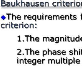
 US patent No HP 200A s schematic") M2-3 Signal Generators Bill Hewlett and Dave Packard s 1 st product (1939) US patent No.2267782 1 HP 200A s schematic 2 1 The basic structure of a sinusoidal oscillator. A positive feedback loop is formed
M2-3 Signal Generators Bill Hewlett and Dave Packard s 1 st product (1939) US patent No.2267782 1 HP 200A s schematic 2 1 The basic structure of a sinusoidal oscillator. A positive feedback loop is formed
The Hartley Oscillator
 The Hartley Oscillator One of the main disadvantages of the basic LC Oscillator circuit we looked at in the previous tutorial is that they have no means of controlling the amplitude of the oscillations
UNIT 4 BIASING AND STABILIZATION
 UNIT 4 BIASING AND STABILIZATION TRANSISTOR BIASING: To operate the transistor in the desired region, we have to apply external dec voltages of correct polarity and magnitude to the two junctions of the
INSTITUTE OF AERONAUTICAL ENGINEERING (Autonomous) Dundigal, Hyderabad
 Dundigal, Hyderabad") INTITUTE OF AERONAUTICAL ENGINEERING (Autonomous) Dundigal, Hyderabad - 500 043 ELECTRICAL AND ELECTRONIC ENGINEERING COURE DECRIPTION FORM Course Title Course Code Regulation Course tructure Course Coordinator
INTITUTE OF AERONAUTICAL ENGINEERING (Autonomous) Dundigal, Hyderabad - 500 043 ELECTRICAL AND ELECTRONIC ENGINEERING COURE DECRIPTION FORM Course Title Course Code Regulation Course tructure Course Coordinator
DE52/DC52 FUNDAMENTALS OF ELECTRICAL & ELECT ENGG DEC 2014
 Q.2 a. Derive an expression for the current flowing at any instant during the discharge of a capacitor C across a resistor R. b. The coil of a moving coil instrument is wound with 50 turns of wire. The
Lecture (10) Power Amplifiers (2)
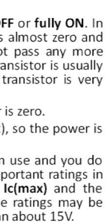
 Power Amplifiers (2)") Lecture (10) Power Amplifiers (2) By: Dr. Ahmed ElShafee ١ Class B/AB Power the ideal maximum peak output current for both dual supply and single supply push pull amplifiers is approximately Ic(sat), and
Lecture (10) Power Amplifiers (2) By: Dr. Ahmed ElShafee ١ Class B/AB Power the ideal maximum peak output current for both dual supply and single supply push pull amplifiers is approximately Ic(sat), and
Chapter 6. FM Circuits
 Chapter 6 FM Circuits Topics Covered 6-1: Frequency Modulators 6-2: Frequency Demodulators Objectives You should be able to: Explain the operation of an FM modulators and demodulators. Compare and contrast;
REV NO EXPERIMENT NO 1 AIM: To study the PN junction diode characteristics under Forward & Reverse bias conditions. APPARATUS REQUIRED:
 KARNAL INSTITUTE OF TECHNOLOGY & MANAGEMENT KUNJPURA, KARNAL LAB MANUAL OF ------- SUBJECT CODE DATE OF ISSUE: SEMESTER: BRANCH: REV NO EXPERIMENT NO 1 AIM: To study the PN junction diode characteristics
Communication Circuit Lab Manual
 German Jordanian University School of Electrical Engineering and IT Department of Electrical and Communication Engineering Communication Circuit Lab Manual Experiment 2 Tuned Amplifier Eng. Anas Alashqar
SUMMER 13 EXAMINATION Subject Code: Model Answer Page No: / N
 Important Instructions to examiners: 1) The answers should be examined by key words and not as word-to-word as given in the model answer scheme. 2) The model answer and the answer written by candidate
Scheme & Syllabus. B.Sc. Electronics. Honours Course. I st & II nd Semester. w.e.f. July Devi Ahilya Vishwavidyalaya, Indore (M.P.
 Scheme & Syllabus of B.Sc. Electronics Honours Course I st & II nd Semester w.e.f. July 2011 Devi Ahilya Vishwavidyalaya, Indore (M.P.), 452001 SEMESTER SYSTEM, 2011-2014 PROPOSED SCHEME FOR B.Sc. ELECTRONICS
GUJARAT TECHNOLOGICAL UNIVERSITY, AHMEDABAD, GUJARAT. Course Curriculum ANALOG ELECTRONICS. (Code: ) Electronics and Communication Engineering
 Electronics and Communication Engineering") GUJARAT TECHNOLOGICAL UNIVERSITY, AHMEDABAD, GUJARAT Course Curriculum ANALOG ELECTRONICS (Code: 333110) Diploma Programme in which this course is offered Semester in which offered Electronics and Communication
GUJARAT TECHNOLOGICAL UNIVERSITY, AHMEDABAD, GUJARAT Course Curriculum ANALOG ELECTRONICS (Code: 333110) Diploma Programme in which this course is offered Semester in which offered Electronics and Communication
Scheme Q.1 Attempt any SIX of following: 12-Total Marks a) Draw symbol NPN and PNP transistor. 2 M Ans: Symbol Of NPN and PNP BJT (1M each)
 Draw symbol NPN and PNP transistor. 2 M Ans: Symbol Of NPN and PNP BJT (1M each)") Q. No. WINTER 16 EXAMINATION (Subject Code: 17319) Model Answer Important Instructions to examiners: 1) The answers should be examined by key words and not as word-to-word as given in the model answer
Q. No. WINTER 16 EXAMINATION (Subject Code: 17319) Model Answer Important Instructions to examiners: 1) The answers should be examined by key words and not as word-to-word as given in the model answer
ELECTRONIC CIRCUITS. Time: Three Hours Maximum Marks: 100
 EC 40 MODEL TEST PAPER - 1 ELECTRONIC CIRCUITS Time: Three Hours Maximum Marks: 100 Answer five questions, taking ANY TWO from Group A, any two from Group B and all from Group C. All parts of a question
Unijunction Transistor. T.Y.B.Sc - Eletronics POWER ELETRONICS
 Unijunction Transistor T.Y.B.Sc - Eletronics POWER ELETRONICS Unijunction Transistor Symbol and Construction The Unijunction Transistor is solid state three terminal device that can be used in gate pulse,
LESSON PLAN. SUBJECT: LINEAR IC S AND APPLICATION NO OF HOURS: 52 FACULTY NAME: Mr. Lokesh.L, Hema. B DEPT: ECE. Portions to be covered
 LESSON PLAN SUBJECT: LINEAR IC S AND APPLICATION SUB CODE: 15EC46 NO OF HOURS: 52 FACULTY NAME: Mr. Lokesh.L, Hema. B DEPT: ECE Class# Chapter title/reference literature Portions to be covered MODULE I
SET - 1 Code No: II B. Tech II Semester Regular Examinations, April/May 2009
 SET - 1 Code No: 3220401 II B. Tech II Semester Regular Examinations, April/May 2009 PULSE AND DIGITAL CIRCUITS ( Common to E.C.E, B.M.E, E.Con.E, I.C.E ) Time: 3 hours Max Marks: 80 Answer Any FIVE Questions
The shape of the waveform will be the same, but its level is shifted either upward or downward. The values of the resistor R and capacitor C affect
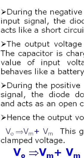
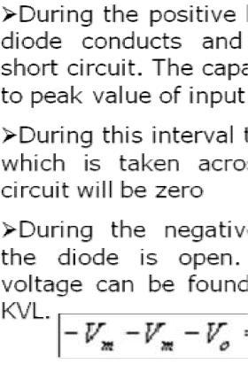
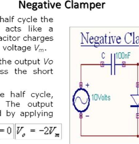
 Diode as Clamper A clamping circuit is used to place either the positive or negative peak of a signal at a desired level. The dc component is simply added or subtracted to/from the input signal. The clamper
Transistors and Applications
 Chapter 17 Transistors and Applications DC Operation of Bipolar Junction Transistors (BJTs) The bipolar junction transistor (BJT) is constructed with three doped semiconductor regions separated by two
ELECTRONIC CIRCUITS LAB
 ELECTRONIC CIRCUITS LAB 1 2 STATE INSTITUTE OF TECHNICAL TEACHERS TRAINING AND RESEARCH GENERAL INSTRUCTIONS Rough record and Fair record are needed to record the experiments conducted in the laboratory.
Syllabus SYLLABUS: INSTRUCTIONAL OBJECTIVES. At the end of the course the students will be able to:
 Syllabus COURSE CODE: COURSE TITLE: EE0208 ELECTRONIC CIRCUITS SYLLABUS: PURPOSE To enable the students to have a fair knowledge about the h-parameters r-parameter in the transistors, amplifiers, basic
Power Amplifiers. Class A Amplifier
 Power Amplifiers The Power amplifiers amplify the power level of the signal. This amplification is done in the last stage in audio applications. The applications related to radio frequencies employ radio
BASIC ELECTRONICS CERTIFICATION COMPETENCIES
 ANALOG BASICS (EM3) of the Associate C.E.T. BASIC ELECTRONICS CERTIFICATION COMPETENCIES (As suggested from segmenting the Associate CET Competencies into 6 BASIC areas: DC; AC; Analog; Digital; Comprehensive;
multivibrator; Introduction to silicon-controlled rectifiers (SCRs).
.") Appendix The experiments of which details are given in this book are based largely on a set of 'modules' specially designed by Dr. K.J. Close. These 'modules' are now made and marketed by Irwin-Desman
Appendix The experiments of which details are given in this book are based largely on a set of 'modules' specially designed by Dr. K.J. Close. These 'modules' are now made and marketed by Irwin-Desman
Code: 9A Answer any FIVE questions All questions carry equal marks *****
 II B. Tech II Semester (R09) Regular & Supplementary Examinations, April/May 2012 ELECTRONIC CIRCUIT ANALYSIS (Common to EIE, E. Con. E & ECE) Time: 3 hours Max Marks: 70 Answer any FIVE questions All
Introductory Electronics for Scientists and Engineers
 Introductory Electronics for Scientists and Engineers Second Edition ROBERT E. SIMPSON University of New Hampshire Allyn and Bacon, Inc. Boston London Sydney Toronto Contents Preface xiü 1 Direct Current
UNIT-I CIRCUIT CONFIGURATION FOR LINEAR
 UNIT-I CIRCUIT CONFIGURATION FOR LINEAR ICs 2 marks questions 1.Mention the advantages of integrated circuits. *Miniaturisation and hence increased equipment density. *Cost reduction due to batch processing.
PHYS225 Lecture 6. Electronic Circuits
 PHYS225 Lecture 6 Electronic Circuits Transistors History Basic physics of operation Ebers-Moll model Small signal equivalent Last lecture Introduction to Transistors A transistor is a device with three
R05. For the circuit shown in fig.1, a sinusoidal voltage of peak 75V is applied. Assume ideal diodes. Obtain the output waveforms.
 Code.No: 33051 R05 SET-1 JAWAHARLAL NEHRU TECHNOLOGICAL UNIVERSITY HYDERABAD II.B.TECH - I SEMESTER SUPPLEMENTARY EXAMINATIONS NOVEMBER, 2009 (Common to EEE, ECE, EIE, ETM) Time: 3hours Max.Marks:80 Answer
MAHALAKSHMI ENGINEERING COLLEGE TIRUCHIRAPALLI
 MAHALAKSHMI ENGINEERING COLLEGE TIRUCHIRAPALLI-621213. QUESTION BANK DEPARTMENT: EEE SUBJECT CODE: EE2203 SEMESTER : III SUBJECT NAME: ELECTRONIC DEVICES &CIRCUITS UNIT 4-AMPLIFIERS AND OSCILLATORS PART
Analogue Electronic Systems
 Unit 47: Unit code Analogue Electronic Systems F/615/1515 Unit level 5 Credit value 15 Introduction Analogue electronic systems are still widely used for a variety of very important applications and this
BEC402-ELECTRONIC CIRCUITS
 BEC402-ELECTRONIC CIRCUITS UNIT- I BASIC DEVICE STABILIZATION AND LOW FREQUENCY DESIGN ANALYSIS Circuits for BJT, DC and AC Load lines, Stability factor analysis, Temperature compensation methods, biasing
Signal Generators and Waveform-Shaping Circuits
 CHAPTER 18 Signal Generators and Waveform-Shaping Circuits Figure 18.1 The basic structure of a sinusoidal oscillator. A positive-feedback loop is formed by an amplifier and a frequency-selective network.
Electronic PRINCIPLES
 MALVINO & BATES Electronic PRINCIPLES SEVENTH EDITION Chapter 22 Nonlinear Op-Amp Circuits Topics Covered in Chapter 22 Comparators with zero reference Comparators with non-zero references Comparators
GATE: Electronics MCQs (Practice Test 1 of 13)
") GATE: Electronics MCQs (Practice Test 1 of 13) 1. Removing bypass capacitor across the emitter leg resistor in a CE amplifier causes a. increase in current gain b. decrease in current gain c. increase
GATE: Electronics MCQs (Practice Test 1 of 13) 1. Removing bypass capacitor across the emitter leg resistor in a CE amplifier causes a. increase in current gain b. decrease in current gain c. increase
EE301 ELECTRONIC CIRCUITS CHAPTER 2 : OSCILLATORS. Lecturer : Engr. Muhammad Muizz Bin Mohd Nawawi
 EE301 ELECTRONIC CIRCUITS CHAPTER 2 : OSCILLATORS Lecturer : Engr. Muhammad Muizz Bin Mohd Nawawi 2.1 INTRODUCTION An electronic circuit which is designed to generate a periodic waveform continuously at