Miniature Contactors & Starters. Series CA8 family of Contactors, Starters, and Overload & Industrial Relays
|
|
|
- Roxanne Mathews
- 5 years ago
- Views:
Transcription


1 Miniature & Starters Series family of, Starters, and Overload & Industrial Relays
2 Miniature, Starters, Overload Relays & Industrial Controls List Prices shown in this selection guide are for use in the US. For Canadian list prices see Price Index PL-_CDN. Series & CAT8 Miniature & Starters Description... A145.1 Catalog Number Coding... A145.4 Miniature... A145.5 CAT8 Miniature Starters... A145.8 Accessories... A Technical Information... A Series CT8 Thermal Overload Relays Description... B32.1 Selection Guide... B32.2 Technical Information... B32.3 Dimensions... B32.5 Series CS8 Industrial Control Relays Description... G12.1 Selection Guide... G12.2 Technical Information... G12.5 Numerical Index -...A P02...A145.10, G12.3 -P04...A145.10, G12.4 -P11...A145.10, G12.5 -P13...A145.10, G12.6 -P20...A145.10, G12.7 -P22...A145.10, G12.8 -P31...A145.10, G12.9 -P40...A145.10, G W453...A W454...A WT...A CAT8-...A145.8 CAU8-...A145.7 CAUT8-...A145.9 CAUT8-PW...A CM8...A CRC G12.4 CRC A CRC A145.11, G12.4 CRC A145.11, G12.4 CRD A145.11, G12.4 CRV A145.11, G12.4 CRV A145.11, G12.4 CRV A145.11, G12.4 CS8-22Z-...G12.2 CS8-31Z-...G12.2 CS8-40E-...G12.2 CS8C-22Z-...G12.2 CS8C-31Z-...G12.2 CS8C-40E-...G12.2 CS8C-L22Z-...G12.2 CS8-L22Z-...G12.2 CS8-P02E...A145.10, G12.3 CS8-P04E...A145.10, G12.3 CS8-P11E...A145.10, G12.3 CS8-P13Z...A145.10, G12.3 CS8-P20E...A145.10, G12.3 CS8-P22Z...A145.10, G12.3 CS8-P31Z...A145.10, G12.3 CS8-P40E...A145.10, G12.3 CT8-A16...A145.12, B32.2 CT8-A25...A145.12, B32.2 CT8-A40...A145.12, B32.2 CT8-A50...A145.12, B32.2 CT8-A63...A145.12, B32.2 CT8-A80...A145.12, B32.2 CT8-B10...A145.12, B32.2 CT8-B13...A145.12, B32.2 CT8-B16...A145.12, B32.2 CT8-B20...A145.12, B32.2 CT8-B25...A145.12, B32.2 CT8-B32...A145.12, B32.2 CT8-B40...A145.12, B32.2 CT8-B48...A145.12, B32.2 CT8-B63...A145.12, B32.2 CT8-B75...A145.12, B32.2 CT8-C10...A145.12, B32.2 CT8-C12...A145.12, B32.2 KT7-25S-PEK12...A145.11
. The is an economical choice for applications where space is limited or where a minimal enclosure is desired.")

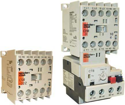
3 A Series and CAT8 Starters An ingenious miniature contactor and starter system Sprecher + Schuh s New Series of miniature contactors and starters provide an extremely compact and reliable method of controlling motors of 7.5 HP or less (@460V). The is an economical choice for applications where space is limited or where a minimal enclosure is desired. Small but rugged Even though their contacts and coils are not replaceable, Sprecher + Schuh has subjected this series of contactors to monitored endurance tests that demonstrate their ruggedness. At full load, under 3-phase power, the contacts in the have an electrical life of 700,000 operations, while the AC magnet system has a mechanical life of 15,000,000 operations. The CAT8 Starter Efficient and reliable This miniature starter features the new CT8 Thermal Overload Relay. A complex current limiting calibration procedure performed after each unit is what ensures the consistent high quality of Sprecher + Schuh s thermal overload relay. Today s, Class 10 T-frame design like the CT Series has been recognized by many motor manufacturers as the ideal type to assure optimum motor protection due to less use of copper and iron. use of enclosures with shallow mounting depths. Once the is installed, all auxiliary contact blocks can be snapped-on or removed without changing any existing power wiring. Other accessories include a snap-on RC Link (surge suppressor), mechanical interlocks and space saving adaptors for connecting auxiliary components. Effortless installation Both the Contactor and the CAT8 Starter are DIN-rail mountable for instant installation and modification. Fittings are also included on the for base mounting. All terminals are clearly marked and shipped in the open position for installation with either manual or power screwdrivers. Accessories require no additional panel space CAT8 starters feature the new CT8 thermal overload. The entire System is logically engineered. Modular accessories like auxiliary contact blocks snap-on without increasing the s original width of 45mm. Also, due to its horizontal switching movement, the basic contactor has the same low profile whether an AC or DC operating magnet is used. This permits the 45mm ( 1 7/16 ) 9A 12A A145.1


")


4 Series Miniature, Starters, Overloads & Industrial Relays A Rated 690V RoHs Compliant Conforming to U.S., Canadian, and IEC Standards Same Dimensions for AC and DC Pluggable Surge Suppressor Modules Suppressor modules are simply plugged on the front of the contactors, next to the auxiliary contact blocks. No wiring required. Fast and easy installation. Auxiliary Contact Reliability Bifurcated, AgNi (silver/nickel) plated contacts for high contact reliability for 15V/2 ma electronic signals. H-shaped self cleaning auxiliary contacts provide a 4-way current path ensure high contact reliability for low energy switching. A145.2


5 A 125% 110% 100% 85% 71%.30 V SAFETY MARGIN FOR OVER VOLTAGE.26,4 V IEC/EN 60947: Mini.24 V 85% - 110% 71% - 125%.20,4 V SAFETY MARGIN FOR UNDER VOLTAGE.17 V High Performance AC & DC Coils VOLTAGE Wide range DC coils can provide reliability in case of over- and under-voltage, a common issue with battery-fed control power supply systems. The low coil consumption allows the contactors to be directly controlled via a PLC. Optional, integral factory-installed surge suppressor modules for AC and DC for limiting coil switching transients. MIRROR AND MECHANICALLY LINKED DESIGN Main Contacts Auxiliary contacts A1 Off A a a 2a 0.5 mm 2a 0.5 mm : mechanically linked performance between main contacts and internal auxiliary contacts. This feature provides status feedback in the event of a contact weld. All Around Safety /Auxiliary contacts: mirror contact between main and auxiliary contacts as per IEC prevent any unclear status indications if a N.O. power pole welds. A145.3
6 Catalog Number Coding Open Catalog Number Coding Sprecher+Schuh employs a catalog number coding system for contactors (and many other devices) that follows a logical pattern, where every digit signifies a specific device attribute. Where indicated, the use of dashes ( ) serves to separate device characteristics and should always be used when ordering. The following example illustrates all of the possible combinations when specifying contactors and reversing contactors (open type only). A CA Z CA CAU Configuration Contactor Reversing Contactor Contactor Series Series 8-9(C) 8-12(C) Auxiliary Contacts -10 N.O. Auxiliary -01 N.C. Auxiliary 4-pole -M40 4 N.O. Power Poles -M31 3 N.O. Power Poles/ 1 N.C. Power Pole -M22 2 N.O. Power Poles/ 2 N.C. Power Poles Coil Code AC DC 24(Z) 12D D(D) D D D 480 This illustration is for reference only. Turn to the appropriate page to determine specific catalog number & pricing. (C) suffix designates with DC coils. On four pole contactors, this number designates main power pole configuration. A145.4
![Miniature - AC & DC Coil Series A Non-Reversing, Three Pole With AC Coil, Series (Open type only) I e [A] 40ºC Ratings for Switching AC Motors (AC2 / AC3 / AC4) 3 Ø kw (50 Hz) UL/CSA HP (60 Hz) 1 Ø](/docs-images/81/84422798/images/7-0.jpg "3Ø Auxiliary Contacts per Contactor 400V AC-1 230V 415V 500V 115V 230V 200V 230V 460V 575V NO NC 20 3 4 4 1/2 1-1/2 2 2 5 5")
7 Miniature - AC & DC Coil Series A Non-Reversing, Three Pole With AC Coil, Series (Open type only) I e [A] 40ºC Ratings for Switching AC Motors (AC2 / AC3 / AC4) 3 Ø kw (50 Hz) UL/CSA HP (60 Hz) 1 Ø 3Ø Auxiliary Contacts per Contactor 400V AC-1 230V 415V 500V 115V 230V 200V 230V 460V 575V NO NC /2 1-1/ / /2 7-1/2 Open Type Catalog Number Price contactor Non-Reversing, Three Pole With DC Coil, Series (Open type only) I e [A] 40ºC Ratings for Switching AC Motors (AC2 / AC3 / AC4) 3 Ø kw (50 Hz) UL/CSA HP (60 Hz) 1 Ø 3Ø Auxiliary Contacts per Contactor 400V AC-1 230V 415V 500V 115V 230V 200V 230V 460V 575V NO NC /2 1-1/ / /2 7-1/2 Open Type Catalog Number Price 1 0-9C C C C A.C. Coil Codes AC Coil Code Voltage Range 50 Hz 60 Hz 12 12V 12V 24Z 24V 24V 48 48V 48V V 120V V-220V 200V-220V V 240V 380 Use Coil Code V 400V V 480V 575 Use Coil Code V 600V Ordering Instructions Specify Catalog Number Replace ( ) with Coil Code D.C. Coil Codes DC Coil Code Voltage 12D 12V 24D 24V 48D 48V 110D 110V 125D 125V 220D 220V See Coil Code table on this page for codes not available without coil. Coils and contacts not replaceable. Select Coil Code from D.C. Coil Code table only. The coil codes shown are the most commonly stocked items. Contact your Sprecher + Schuh representative to determine if special voltages, are required. Integrated diode surge suppressor coils available. Order coil code 24DD and add $25 to list price. Ex: -9C-10-24D becomes -9C-10-24DD. The European Community has agreed that 400V is the nominal voltage in lieu of 380V. Use this code when 380V is required. Use this code for 575V applications. A145.5
8 Miniature - AC & DC Coil Series Non-Reversing, Four Pole With AC Coil, Series (Open type only) I e [A] 40ºC Ratings for Switching AC Motors (AC2 / AC3) 3 Ø kw (50 Hz) UL/CSA HP (60 Hz) 1 Ø 3Ø Contact configuration main poles 400V AC-1 230V 415V 500V 115V 230V 200V 230V 460V 575V NO NC /2 1-1/ / /2 7-1/2 Open Type Catalog Number Price M M M M M M M40 contactor A Non-Reversing, Four Pole With DC Coil, Series (Open type only) I e [A] 40ºC Ratings for Switching AC Motors (AC2 / AC3) 3 Ø kw (50 Hz) UL/CSA HP (60 Hz) 1 Ø 3Ø Contact configuration main poles 400V AC-1 230V 415V 500V 115V 230V 200V 230V 460V 575V NO NC /2 1-1/ / /2 7-1/2 Open Type Catalog Number Price 4 0-9C-M C-M C-M C-M C-M C-M A.C. Coil Codes AC Coil Code Voltage Range 50 Hz 60 Hz 12 12V 12V 24Z 24V 24V 48 48V 48V V 120V V-220V 200V-220V V 240V 380 Use Coil Code V 400V V 480V 575 Use Coil Code V 600V Ordering Instructions Specify Catalog Number Replace ( ) with Coil Code D.C. Coil Codes DC Coil Code Voltage 12D 12V 24D 24V 48D 48V 110D 110V 125D 125V 220D 220V See Coil Code table on this page for codes not available without coil. Coils and contacts not replaceable. Select Coil Code from D.C. Coil Code table only. The coil codes shown are the most commonly stocked items. Contact your Sprecher + Schuh representative to determine if other voltages. No auxiliary contacts provided in the base of a. Add auxiliaries from pg. A Integrated diode surge suppressor coils available. Order coil code 24DD and add $25 to list price. Ex: -9C-10-24D becomes -9C-10-24DD. The European Community has agreed that 400V is the nominal voltage in lieu of 380V. Use this code when 380V is required. Use this code for 575V applications. A145.6
![Miniature Reversing Series CAU8 A Reversing, Three Pole With AC Coil, Series CAU8 (Open type only) I e [A] 40ºC Ratings for Switching AC Motors (AC2 / AC3 / AC4) 3 Ø kw (50 Hz) UL/CSA HP (60 Hz) 1 Ø](/docs-images/81/84422798/images/9-0.jpg "3Ø Auxiliary Contacts per Contactor 400V AC-1 230V 415V 500V 115V 230V 200V 230V 460V 575V NO NC 20 3 4 4 1/2 1-1/2 2 2 5 5")
9 Miniature Reversing Series CAU8 A Reversing, Three Pole With AC Coil, Series CAU8 (Open type only) I e [A] 40ºC Ratings for Switching AC Motors (AC2 / AC3 / AC4) 3 Ø kw (50 Hz) UL/CSA HP (60 Hz) 1 Ø 3Ø Auxiliary Contacts per Contactor 400V AC-1 230V 415V 500V 115V 230V 200V 230V 460V 575V NO NC /2 1-1/ / /2 7-1/2 Open Type Catalog Number Price 0 1 CAU LW CAU PW CAU LW CAU PW 215 CAU8 LW Includes: Reversing, Three Pole With DC Coil, Series CAU8 (Open type only) I e [A] 40ºC Ratings for Switching AC Motors (AC2 / AC3 / AC4) 3 Ø kw (50 Hz) UL/CSA HP (60 Hz) 1 Ø 3Ø Auxiliary Contacts per Contactor 400V AC-1 230V 415V 500V 115V 230V 200V 230V 460V 575V NO NC /2 1-1/ / /2 7-1/2 Open Type Catalog Number Price 0 1 CAU8-9C-02- -LW CAU8-9C-42- -PW CAU8-12C-02- -LW CAU8-12C-42- -PW 275 CAU8 PW Includes: interlock wiring (using Wiring Kit Cat.# CAUT8-PW) block (Cat.# -P20 on the -42- models) A.C. Coil Codes AC Coil Code Voltage Range 50 Hz 60 Hz 12 12V 12V 24Z 24V 24V 48 48V 48V V 120V V-220V 200V-220V V 240V 380 Use Coil Code V 400V V 480V 575 Use Coil Code V 600V Ordering Instructions Specify Catalog Number Replace ( ) with Coil Code D.C. Coil Codes DC Coil Code Voltage 12D 12V 24D 24V 48D 48V 110D 110V 125D 125V 220D 220V See Coil Code table on this page for codes not available without coil. Coils and contacts not replaceable. Internal NC contacts on each contactor are used for electrical interlocking. The coil codes shown are the most commonly stocked items. Contact your Sprecher + Schuh representative to determine if other voltages are required. Integrated diode surge suppressor coils available. Order coil code 24DD and add $50 to list price. Ex: CAU8-9C-02-24D becomes CAU8-9C-02-24DD. The European Community has agreed that 400V is the nominal voltage in lieu of 380V. Use this code when 380V is required. Use this code for 575V applications. A145.7
![Miniature Starters, AC & DC Coil Series CAT8 Non-Reversing, Three Pole Starters With AC Coil, Series CAT8 (Open type only) I e [A] 40ºC Ratings for Switching AC Motors (AC2 / AC3 / AC4) 3 Ø kw (50](/docs-images/81/84422798/images/10-0.jpg "Hz) UL/CSA HP (60 Hz) 1 Ø 3Ø Auxiliary Contacts per Contactor 400V AC-1 230V 415V 500V 115V 230V 200V 230V 460V 575V NO NC 20 3 4 4 1/2 1-1/2 2 2 5 5")
10 Miniature Starters, AC & DC Coil Series CAT8 Non-Reversing, Three Pole Starters With AC Coil, Series CAT8 (Open type only) I e [A] 40ºC Ratings for Switching AC Motors (AC2 / AC3 / AC4) 3 Ø kw (50 Hz) UL/CSA HP (60 Hz) 1 Ø 3Ø Auxiliary Contacts per Contactor 400V AC-1 230V 415V 500V 115V 230V 200V 230V 460V 575V NO NC /2 1-1/ / /2 7-1/2 Open Type Catalog Number Price 1 0 CAT CAT CAT CAT A Non-Reversing, Three Pole Starters With DC Coil, Series CAT8 (Open type only) I e [A] 40ºC Ratings for Switching AC Motors (AC2 / AC3 / AC4) 3 Ø kw (50 Hz) UL/CSA HP (60 Hz) 1 Ø 3Ø Auxiliary Contacts per Contactor 400V AC-1 230V 415V 500V 115V 230V 200V 230V 460V 575V NO NC /2 1-1/ / /2 7-1/2 Open Type Catalog Number Price 1 0 CAT8-9C CAT8-9C CAT8-12C CAT8-12C Representative model of a CAT8-9 starter with the CT8 bimetallic overload relay NOTE: CAT8 starters are priced to include Sprecher + Schuh s economical CT8 bimetallic overload relay. See page A for selection. A.C. Coil Codes AC Coil Code Voltage Range 50 Hz 60 Hz 12 12V 12V 24Z 24V 24V 48 48V 48V V 120V V-220V 200V-220V V 240V 380 Use Coil Code V 400V V 480V 575 Use Coil Code V 600V Ordering Instructions Specify Catalog Number Replace ( ) with Coil Code Replace ( ) with O/L Relay Code D.C. Coil Codes DC Coil Code 12D 24D 48D 110D 125D 220D Voltage 12V 24V 48V 110V 125V 220V Coil Codes on this page O/L Relay Code on A not available without coil. Coils and contacts not replaceable. Select Coil Code from D.C. Coil Code table only. The coil codes shown are the most commonly stocked items. Contact your Sprecher + Schuh representative to determine if other voltages are required. Integrated diode surge suppressor coils available. Order coil code 24DD and add $25 to list price. Ex: CAT8-9C-10-24D becomes CAT8-9C-10-24DD. The European Community has agreed that 400V is the nominal voltage in lieu of 380V. Use this code when 380V is required. Use this code for 575V applications. A145.8
![Miniature Starters, AC and DC Coil Reversing Series CAUT8 A Reversing, Three Pole Starters With AC Coil, Series CAUT8 (Open type only) I e [A] 40ºC Ratings for Switching AC Motors (AC2 / AC3 / AC4) 3](/docs-images/81/84422798/images/11-0.jpg "Ø kw (50 Hz) UL/CSA HP (60 Hz) 1 Ø 3Ø Auxiliary Contacts per Contactor 400V AC-1 230V 415V 500V 115V 230V 200V 230V 460V 575V NO NC 20 3 4 4 1/2 1-1/2 2 2 5 5")
11 Miniature Starters, AC and DC Coil Reversing Series CAUT8 A Reversing, Three Pole Starters With AC Coil, Series CAUT8 (Open type only) I e [A] 40ºC Ratings for Switching AC Motors (AC2 / AC3 / AC4) 3 Ø kw (50 Hz) UL/CSA HP (60 Hz) 1 Ø 3Ø Auxiliary Contacts per Contactor 400V AC-1 230V 415V 500V 115V 230V 200V 230V 460V 575V NO NC /2 1-1/ / /2 7-1/2 Open Type Catalog Number Price 0 1 CAUT LW CAUT PW CAUT LW CAUT PW 261 Reversing, Three Pole Starters With DC Coil, Series CAUT8 (Open type only) I e [A] 40ºC Ratings for Switching AC Motors (AC2 / AC3 / AC4) 3 Ø kw (50 Hz) UL/CSA HP (60 Hz) 1 Ø 3Ø Auxiliary Contacts per Contactor 400V AC-1 230V 415V 500V 115V 230V 200V 230V 460V 575V NO NC /2 1-1/ / /2 7-1/2 Open Type Catalog Number Price 0 1 CAUT8-9C LW CAUT8-9C PW CAUT8-12C LW CAUT8-12C PW 321 CAUT8 LW Includes: overload relay. Select code from page A CAUT8 PW Includes: electrical interlock overload relay. Select code from page A wiring (using Wiring Kit Cat.# CAUT8-PW) block (Cat.# -P20 on the -42- models) A.C. Coil Codes AC Coil Code Voltage Range 50 Hz 60 Hz 12 12V 12V 24Z 24V 24V 48 48V 48V V 120V V-220V 200V-220V V 240V 380 Use Coil Code V 400V V 480V 575 Use Coil Code V 600V Ordering Instructions Specify Catalog Number Replace ( ) with Coil Code Replace ( ) with O/L Relay Code D.C. Coil Codes DC Coil Code Voltage 12D 12V 24D 24V 48D 48V 110D 110V 125D 125V 220D 220V Coil Codes on this page O/L Relay Code on A not available without coil. Coils and contacts not replaceable. NC contacts on each contactor are used for electrical interlocking. The coil codes shown are the most commonly stocked items. Contact your Sprecher + Schuh representative to determine if other voltages are required. Integrated diode surge suppressor coils available. Order coil code 24DD and add $50 to list price. Ex: CAUT8-9C-02-24D becomes CAUT8-9C-02-24DD. The European Community has agreed that 400V is the nominal voltage in lieu of 380V. Use this code when 380V is required. Use this code for 575V applications. A145.9


12 Accessories - Field Installable Miniature & Starters Auxiliary Contact Blocks (2 & 4 Pole) Auxiliary Contact Blocks NO NC Contact Arrangement Catalog No. Price 1 1 -P11 Auxiliary Contact Blocks NO NC Contact Arrangement Catalog No. Price 1 1 CS8-P11E A 0 2 -P CS8-P02E 16 2-Pole 2 0 -P20 2-Pole 2 0 CS8-P20E 2 2 -P CS8-P22Z Typical auxiliary contact block Typical auxiliary contact block 3 1 -P CS8-P31Z 1 3 -P CS8-P13E P CS8-P04E 4-Pole 4 0 -P40 4-Pole 4 0 CS8-P40E Control Modules Module Description For use with... Connection Diagrams Function Catalog Number Price Pluggable electronic timer ON-Delay The contactor is energized at the end of the delay time. all V 50/60Hz sec sec VDC sec sec CRZE /240 CRZE /240 CRZE8-3-24/48VDC CRZE /48VDC 60 Pluggable electronic timer OFF-Delay The timer switches off after the set time has elapsed all V 50/60Hz sec CRZA / VDC sec CRZA /48VDC 60 Auxiliary contacts mirror contact performance per IEC Contacts are bifurcated (H-bridge) with a minimum rating of 15V. A145.10


13 Accessories - Field Installable Miniature & Starters A Miscellaneous Accessories Accessory Description Catalog Number Price Surge Suppressor CR 8 - for limiting voltage spikes when switching off coil. Coil itself provides sufficient limitation at voltages over 240V. RC Link (Type CRC8 ) for AC Control 24-48VAC VAC VAC Diode Link (Type CRD8 ) for DC Control VDC (diode) Varistor Link (Type CRV8 )for AC/DC Control 12-55VAC/12-77VDC VAC/78-180VDC VAC/ VDC CRC8-50 CRC8-280 CRC8-480 CRD8-250 CRV8-55 CRV8-136 CRV Mechanical Interlock Kit - For interlocking of two adjacent contactor without additional space requirement in width attachable from the front (top) of contactor optional auxiliary contact blocks can be mounted on the top (does not interfere with mounting CR 8) CM8 7 Wiring Kit - For connecting line, load and control wiring of a CAU8 reversing contactor. works with CT8 Overloads CAUT8-PW 9 Connection Modules - For KTA7 motor circuit controller with a contactor. KT7-25S-PEK12 24 Feeder Terminal for Compact Bus Bars - Supply of compact bus bars. For use with -9 and12. -WT 25 Three-Phase Compact Bus Bars - For use with -9 and 12 with 45 mm spacing. (3 connections) -W Three-Phase Compact Bus Bars - For use with -9 and 12 with 45 mm spacing. (4 connections) -W contactors with 24 VDC coils can be special ordered with integrated diodes (built-in) rather than applying CRD8 to the coil terminals. A145.11
14 Overload Relay Codes Series Starters CAT8 Starters with CT8 Thermal Overload Relay For use with contactor... Amp Range Overload Relay Code ( ) Catalog Number (of Overload Relay used) Price Adder CT8 Thermal Overload Relay, 1 or 3-Phase, Auto/Manual, Class A16 CT8-A16 Standard A25 CT8-A25 Standard A40 CT8-A40 Standard A50 CT8-A50 Standard A63 CT8-A63 Standard A80 CT8-A80 Standard B10 CT8-B10 Standard B13 CT8-B13 Standard B16 CT8-B16 Standard B20 CT8-B20 Standard B25 CT8-B25 Standard B32 CT8-B32 Standard B40 CT8-B40 Standard B48 CT8-B48 Standard B63 CT8-B63 Standard B75 CT8-B75 Standard -9 or C10 CT8-C10 Standard C12 CT8-C12 Standard A A145.12
15 Technical Information Miniature A Technical Information Rated Insulation Voltage U i to IEC947-1 [V] 690V UL/CSA [V] 600V Rated Impulse Voltage Withstand U imp [kv] 6 Rated Voltage Ue-Main Contacts AC 50/60Hz [V] 230, 240, 400, 415, 500, 690 DC [V] 24, 48, 110, 220, 440 Operating Frequency for AC Loads [Hz] 50/60Hz Switching Motor Loads Standard IEC Ratings AC-2, AC-3, AC-4 230V [A] DOL & Reversing 240V [A] Hz@60 C 400V [A] V [A] V [A] V [A] V [kw] V [kw] V [kw] V [kw] V [kw] V [kw] UL/CSA 115V [A] DOL & Reversing 1 230V [A] Hz 115V [HP] V [HP] V [A] V [A] V [A] V [A] V [HP] V [HP] V [HP] V [HP] Maximum Operating Rate AC2 [ops/hour] At 9A for AC3; 20A for AC2/4 AC3 [ops/hour] Starting time t A = 0.25s AC4 [ops/hour] AC4 (200,000 Op. Cycles) 230V [A] Hz 240V [A] V [A] V [A] V [A] V [kw] V [kw] V [kw] V [kw] V [kw] Max. Operating Rate [ops/hour] Wye-Delta (Star Delta) 230V [A] Hz 240V [A] V [A] V [A] V [A] V [A] V [kw] V [kw] V [kw] V [kw] V [kw] V [kw] Hz 200V [Hp] V [Hp] V [Hp] V [Hp] AC-1 Load, 3 Switching Ambient Temperature 40 C I e [A] V [kw] V [kw] V [kw] V [kw] V [kw] V [kw] Ambient Temperature 60 C I e [A] V [kw] V [kw] V [kw] V [kw] V [kw] V [kw] Continuous Current (UL/CSA) General Purpose Rating (40 C) Open [A] Enclosed [A] Lighting Loads Gas Dischrg.Lamps-AC-5a, VAC (40ºC) Single compensated Max. capacitance at prospective short circuit current available at the contactor Enclosed [A] Open [A] kA F] kA F] kA F] ~ ~ Incandescent Lamps - AC-5b Electrical endurance~100,000 operations 230/240V [A] A145.13
16 Technical Information Miniature Electrical Data Switching power transformers AC-6a (50Hz) Inrush Rated transformer current = = V [A] V [A] V [A] V [A] V [A] VAC [kva] VAC [kva] VAC [kva] VAC [kva] VAC [kva] VAC [kva] 4 5 DC Ratings DC-1 Rating at 60 C 1 Pole 24VDC [A] /60VDC [A] 6/1.5 6/ VDC [A] VDC [A] VDC [A] Pole in Series 24VDC [A] /60VDC [A] VDC [A] VDC [A] VDC [A] Pole in Series 24VDC [A] VDC [A] VDC [A] VDC [A] VDC [A] Shunt-wound Motors Starting, reverse current braking, reversing stepping DC-3, 60 C 24V [A] Poles in series 48/60V [A] V [A] V [A] V [A] Series-wound Motors Starting, reverse current braking, reversing stepping DC-5, 60 C 24V [A] poles in series 48/60V [A] V [A] V [A] V [A] ~ ~ Short Time Withstand-I CW, 60 C 10s [A] Short Circuit Coordination (Max. Fuse or Circuit Breaker Rating) ka Max. DIN fuse gg per IEC (Contactor and Fuse only) Available Fault Current Type 1 Coordination (690V) max. [A] Type 2 Coordination (690V) max. [A] Class K5 and RK5 fuses max. [A] Resistance and Watt Loss l e AC3 Resistance per power pole [m ] Watt Loss - 3 power [W] Coil and warm [W] power poles DC, warm [W] Coil Data Voltage Range AC: 50Hz, 60Hz, 50/60 Hz Pickup [x Us] Dropout [x Us] DC Pickup [x Us] , 12, 24, 110V DC: Dropout [x Us] Coil Consumption AC: 50Hz, 60Hz, 50/60 Hz Pickup [VA/W] 35/32 Hold-in [VA/W] 5/1.8 DC Pickup [W] cold 3.0, warm 2.6 Hold-in [W] cold 3.0, warm 2.6 Operating Times AC: 50Hz, 60Hz, 50/60 Hz Pickup [ms] Dropout [ms] with RC Suppressor Dropout [ms] DC Pickup [ms] Dropout [ms] with Integ. Suppression Dropout [ms] with external diode Suppression Dropout [ms] Minimal changeover time for reversing [ms] >50 A UL listed combination. A145.14
17 Technical Information Miniature A Mechanical Data -9 Service Life Mechanical AC [Mil.Op.] 15 Electrical AC-3(400V) [Mil.Op.] 0.7 Reversing combination, mechanical, electrical [Mil.Op.] 0.7 Shipping Weights AC- [kg] 0.16 [Lbs] 0.35 AC-CAU8 [kg] 0.35 [Lbs] 0.77 DC- [kg] 0.20 [Lbs] 0.44 DC-CAU8 [kg] 0.43 [Lbs] 0.91 Terminations - Screw Type Terminals Main contacts and Auxiliary contacts -12 Terminal Type Combination Screw Head: Cross, Slotted, Pozidrive Fine 1 wire [mm stranded 2 ] w/ ferrule 2 wires [mm 2 ] Solid or coarse stranded 1 wire 2 wires [mm 2 ] [mm 2 ] [AWG] Torque Requirement [Nm] 1.2 [Lb-in] 10.6 Environmental and General Specifications Ambient Temperature Storage C ( F) Operation C ( F) Conditioned 15% current C ( F) reduction after AC-1 at >60 C Altitude at installed site 2000 meters above sea level per IEC Resistance to Corrosion / Humidity Damp-alternating climate: cyclic to IEC 68-2, 56 cycles. Dry Heat: IEC 68-2, +100 C (212 F), relative humidity <50%, 7 days. Damp tropical: IEC 68-2, +40 C (104 F), relative humidity <92%, 56 days. Shock Resistance IEC 68-2/EN Vibration Resistance IEC 68-2/EN Operating Position Refer to Dimension Pages Standards Approvals IEC/EN , -4-1, -5-1, -5-4; UL 508; CSA No. 14 A145.15
18 Technical Information Miniature Auxiliary Contacts Built-in Auxiliary Contacts Add-on Auxiliary Contacts Current Switching AC-12 I th at 40 C [A] at 60 C [A] 6 6 AC-15, switching electromagnetic loads at: [V] [A] DC-13, switching DC electromagnets at: [V] [A] DC-12, L/R< 1 ms resistive loads at: [V] [A] DC-14, L/R< 15 ms inductive loads [V] with economy resistor in series at: [A] Low Level Signal Switching Contact design X-stamped H-bridge, bi-furcated Minimum switching recommendation [V] 17V 15V [ma] 10mA 2mA Short-Circuit Protection - gg Fuse Type 2 Coordination [A] Load carrying capacity per UL/CSA Rated Voltage AC [V] 600 max. 600 max. Continuous Rating 40 C [A] 10 general purpose 10 general purpose Switching Capacity AC Heavy pilot duty (A600) Heavy pilot duty (B600) Rated Voltage DC [V] 600 max. 600 max. Switching Capacity DC Standard pilot duty (Q600) Standard pilot duty (Q600) Mechanically Linked Contacts IEC , Annex L Yes No Mirror Contacts IEC , Annex F Yes Yes A Contact Ratings (Per NEMA/UL A600, B600 & Q600) Standard A600 Circuit Voltage 120AC 240AC 480AC 600AC Make (Amps/VA) 60A/7200VA 30A/7200VA 15A/7200VA 12A/7200VA Break (Amps/VA) 60A/720VA 30A/720VA 15A/720VA 12A/720VA Continuous Amps 10 B AC 240AC 480AC 600AC 30A/3600VA 15A/3600VA 7.5A/3600VA 6A/3600VA 3.0A/360VA 1.5A/360VA 0.75A/360VA 0.60A/360VA 10 Q DC 250DC DC 0.55/69VA 0.27/69VA 0.1A/69VA 0.55/69VA 0.27/69VA 0.1A/69VA 2.5 A145.16
19 Technical Information Miniature A Determining Contact Life To determine the contactor s estimated electrical life, follow these guidelines: 1. Identify the appropriate Utilization Category from Table A. 2. On the following pages, choose the graph for the Utilization Category selected. 3. Locate the Rated Operational Current (l e ) along the bottom of the chart and follow the graph lines up to the intersection of the appropriate contactor s life-load curve. 4. Read the estimated contact life along the vertical axis. Table A IEC Special Utilization Categories, AC Ratings CONTACTORS CONTROL DEVICES SWITCHES Category Typical Applications AC-1 AC-2 AC-3 AC-4 Non-inductive or slightly inductive loads, resistance furnaces Slip-ring motors: Starting, plugging Squirrel-cage motors: Starting, switching off motors during running Squirrel-cage motors: Starting, plugging, inching Rated Current Conditions for testing electrical life Conditions for testing making and breaking capacity Make Break Ops. Make Break I/Ie U/Ue cos Ic/Ie Ur/Ue cos I/Ie U/Ue cos Ic/Ie Ur/Ue cos All values All values Ie 17Amp 17Amp<Ie 100Amp Ie>100Amp Ie 17Amp 17Amp<Ie 100Amp Ie>100Amp AC-5a Switching of electric discharge lamp control AC-5b Switching of incandescent lamps AC-6a Switching of transformers Rating derived from AC-3 rating (x 0.45) AC-6b Switching of capacity banks Depends on circuit conditions of application Control of resistive loads and solid AC-12 state loads with isolation by opto couplers All values AC-13 Control of solid state loads with transformer isolation AC-14 Control of small electromagnetic loads 72 VA AC-15 Control of electromagnetic loads 72 VA AC-20 Connecting and disconnecting under no load conditions No testing required AC-21 Switching of resistive loads, including moderate loads All values Switching of mixed resistive & AC-22 inductive loads, including All values moderate overloads AC-23 Switching of motor loads or other highly inductive loads All values Ops Legend Ue Rated operational voltage U Voltage before make Ur Recovery voltage Ie Rated operational current I Making current Ic Breaking current L Inductance of test circuit R Resistance of test circuit A Utilization categories and test conditions for AC & DC. For contactors according to IEC 158-1, starters according to IEC and control switches according to IEC and IEC 337-1A. With a minimum value of 1000A for I or Ic. With a minimum value of 800A for Ic. With a minimum value of 1200A for I. Plugging is understood as stopping or reversing the motor rapidly by reversing the motor primary connections while the motor is running. Inching [or jogging] is understood as energizing a motor once or repeatedly for short periods to obtain small movements of the driven mechanism.
20 Technical Information - Contact Life Determining Contact Life To determine the contactor s estimated electrical life, follow these guidelines: 1. Identify the appropriate Utilization Category from Table A. 2. On the following pages, choose the graph for the Utilization Category selected. 3. Locate the Rated Operational Current (l e ) along the bottom of the chart and follow the graph lines up to the intersection of the appropriate contactor s life-load curve. 4. Read the estimated contact life along the vertical axis. A Table A IEC Special Utilization Categories, DC Ratings Conditions for testing electrical life Conditions for testing making and breaking capacity Category Typical Applications Rated Current Make Break Ops Make Break Ops I/Ie U/Ue cos Ic/Ie Ur/Ue cos I/Ie U/Ue cos Ic/Ie Ur/Ue cos DC-1 DC-2 DC-3 DC-4 DC-5 Non-inductive or slightly inductive loads, resistance furnaces Shunt-motors: Starting, switching off motors during running Shunt-motors: Starting, plugging, inching Series-motors: Starting switching off motors during running Series-motors: Starting, plugging, inching All values All values All values All values All values DC-15 Electromagnets for contactors, valves, solenoid actuators All values x P x P x P x P Legend Ue Rated operational voltage U Voltage before make Ur Recovery voltage Ie Rated operational current I Making current Ic Breaking current L Inductance of test circuit R Resistance of test circuit Utilization categories and test conditions for AC & DC. For contactors according to IEC 158-1, starters according to IEC and control switches according to IEC and IEC 337-1A. Only according to VDE. P = Ue x Ie rated power [W]. The value 6 x P has been derived from an empiric relationship which covers most magnetic loads for DC up to an upper limit of P = 50W. A145.18
21 Technical Information Miniature Life Load Curves A Life-Load Curves Current (l e ) along the bottom of the chart and follow the graph lines up to the intersection of the appropriate contactor s life-load curve. along the vertical axis. AC-1, AC3 ( V AC) INSTRUCTIONS ON HOW TO READ LIFE CURVES CAN BE FOUND ON PG. A57. AC-4 ( V AC) NOTE: The life-load curves shown here are based on Sprecher+Schuh tests according to the requirements defined in IEC Since contact life in any given application is dependent on environmental conditions and duty cycle, actual application contact life may vary from that indicated by the curves shown here. A145.19
22 Dimensions Miniature Series & Series CAU8 ( & Reversing ) A A145.20
23 Miniature Series A Notes A145.21

24 Series CT8 Thermal Overload Relays Simple and effective motor protection for applications to 7 1 /2HP@ 460V (10HP@575V) Sprecher + Schuh has been a leader in providing superior motor protection. The new CT8 is an economical thermal overload relay yet includes proven features like Differential tripping, Automatic / Manual reset modes, and isolated alarm circuit contacts as standards. Consistent and reliable protection The consistent high quality of Sprecher + Schuh thermal overload relays is ensured by a complex current calibration procedure performed after each unit is at full operating temperature. Calibration is performed at the largest and smallest current the overload can handle. The accurate time/ current characteristic curve obtained in this manner guarantees reliable motor protection every time. Ambient temperature compensation All Sprecher + Schuh thermal overload relays are temperature compensated. An additional bimetallic ambient compensation strip, built into the conductor-bimetal transmission path, ensures that the tripping characteristics of the relay remain constant over an ambient temperature range of 25 C to +50 C. Single phase applications CT8 Series thermal overload relays can be applied for protection of single phase AC motors. The relays have the same characteristics as shown for three phase operation. To maintain these characteristics, each element of the overload relay must carry the motor current as shown in the schematic on page C88. B Motor Protection CT8 Superior Class 10 characteristics Today s T-Frame motors have less copper and iron that the old U-Frame motors that were popular when traditional Class 20 overload relays were designed. For this reason, faster Class 10 overloads like the CT8 Series have been recognized by many motor manufacturers as the ideal type to assure optimum protection of T frame motors. Protection from single phase conditions A unique feature not found in traditional thermal overload relays provides accelerated tripping under single phase conditions. This is accomplished with a special differential tripping mechanism built into CT8 (see illustration at right). Other standard features CT8 thermal overload relays feature a fail-safe trip-free design that prevents the device from being held closed during an overload. In addition, a selectable lever permits the user the option to choose the manual or automatic reset modes. A separate NO signal contact is also provided on CT8 overloads which is isolated from the NC trip contact. This permits the use of a trip signal voltage different than that of the control voltage. Sprecher + Schuh provides outstanding motor protection with our CT8 Thermal Overload Relay CT8 Thermal Overload Relays offer accelerated tripping under single phase conditions B32.1

25 Thermal Overload Relays Series CT8 B Motor Protection CT8 CT8 Thermal Overload Relays - manual or automatic reset Overload Relay CT8 Directly Mounts to Contactor Adjustment Ranges [A] Trip Class 10 Catalog Number CT8-A CT8-A CT8-A CT8-A CT8-A CT8-A CT8-B CT8-B CT8-B CT8-B CT8-B CT8-B CT8-B CT8-B CT8-B CT8-B75 Price -9 or CT8-C CT8-C Thermal Overload Relay Features: F and DC motors CT8 Thermal Overload Relay Accessories Accessories Description For Use with... Catalog Number Price Each Remote Reset - For remote resetting All CT8 CMR8-47 CMR8 Remote Reset Coil Codes AC Voltage Range Coil Code 50 Hz 60 Hz 24Z 24V 24V V 120V V 240V DC Coil Code 24D 48D 115D Voltage 24V 48V 115V noted will physically attach to the overload realys listed. This reference is not intended to be a guide for selecting contactors. Size overload relays using the full load current of the motor. B32.2
26 Technical Information Series CT8 Thermal Overload Relays Electrical Data General Data Main Circuits Rated Insulation Voltage U i [V] 690 AC Rated Impulse Strength U imp [kv] 6 AC Rated Operating Voltage U e IEC/UL [V] 690/600 AC Weight [kg (oz)] (.25) Standards IEC/EN , -4-1, -5-1; UL508; CSA C22.2 NO. 14 Approvals Terminations - Power Terminal Type M3.5 Fine stranded w/ ferrule [mm 2 ] 2 x (1.5 4) Solid or [mm 2 ] 2 x (1.5 4) coarse stranded [AWG] 2 x (16 10) Torque Requirement [Nm] 1.2 [Lb-in] 10.6 Pozidrive screwdriver Size 2 Slotted screwdriver [mm] 1 x 6 Control Circuits Rated Insulation Voltage U i [V] 690 AC Rated Impulse Strength U imp [kv] 4 AC Rated Operating Voltage U e IEC/UL [V] 690/600 AC Rating Designation A600/Q300 I Rated Operating Current e N.O./N.C. 24V [A] 4 AC V [A] 2 400V [A] V [A] V [A] 2 DC V [A] V [A] V [A] 0.08 Thermal Current I the [A] 5 Chort Circuit Withstand, fuse gg [A] 6 Contact Reliability 15V, 2mA Temperature Compensation Continuous (Temperature Range C per IEC , EN60947; PTB: C) Vibration Resistance (PER IEC ) [G] 3 Shock Resistance (PER IEC ) [G] 30 Type of Protection IP2X Environmental Ambient Temperature Storage ºC ( ºF) Operating ºC ( ºF) Humidity Operating Damp Heat 5 95% Non-condensing per IEC and IEC Max. Altitude [m] 2000 Polution Environment Pollution Degree 3 Protection Type of Relay Ambient Compensated, Time Delay, Phase Loss Sensitive Nature of Relay Bimetallic Overload Relay Trip Rating 120% FLA Trip Class IEC: 10A, UL 10 Reset Mode Automatic or Manual Power dissipation up to 0.4 A 7 W A 6 W B Motor Protection CT8 Terminations - Control Terminal Type M3.5 Fine stranded w/ ferrule [mm 2 ] 2 x (1 4) Solid or [mm 2 ] 2 x (1 4) coarse stranded [AWG] 2 x (18 12) Torque Requirement [Nm] 1.2 [Lb-in] 10.6 Pozidrive screwdriver Size 2 Slotted screwdriver [mm] 1 x 6 B32.3

27 Technical Information Series CT8 Thermal Overload Relays Tripping Characteristics B These trip characteristics refer to IEC and are average values from cold start at an ambient temperature of 20 C. Trip time is pictured as a function of operating current. With the device at normal operating temperature, the trip time decreases to approximately 25% of the shown value. Motor Protection CT8 Connection Diagrams B32.4
28 Dimensions Series CT8 Thermal Overload Relays Series CT O R /T1 2/T1 3/T2 5/T3 4/T2 6/T3 Terminal Marking B Motor Protection CT NO NC T1 4T2 6T B32.5
29 Thermal Overload Relays Series CT8 Notes B Motor Protection CT8 B32.6

30 CS8 Industrial Control Relays The miniature relay system with big advantages CS8 front mount auxiliaries are positive guidance Despite increasing complexity, control systems and installations must become increasingly compact. And the CS8 Miniature Relay System packs maximum performance into minimum space. Small but rugged Sprecher + Schuh has subjected this relay series to monitored endurance tests that demonstrate their ruggedness. Under normal duty, CS8 contacts have an electrical life of 700,000 operations, while the AC magnet system has a mechanical life of 15,000,000 operations. The coil is designed for absolute undervoltage reliability. Undervoltages that do not cause the contactor to close can be withstood indefinitely without damage. The body of the device is sturdy as well. The front housing, containing the phase partitions and screwdriver guides, is manufactured in one piece. Front and rear housing are then joint fitted together. Superior Contact Reliability The standard CS8 base relay and auxiliary contacts are bifurcated H-bridge design which divides each movable contact into two sections at the tip of the spanner which provides a higher degree of reliability for low signal applications. Perfect fit for PLC and other electronic circuits operate at signals as low as 2mA. Accessories require no additional panel space all auxiliary contact blocks can be snapped on or removed without changing any existing wiring. Auxiliary components provide flexibility CS8 auxiliary components allow you to convert the basic four pole relay up to an 8 pole relay. Effortless installation CS8 relays are DIN-rail mountable for instant installation and modification. Fittings are also included for base mounting. All terminals are clearly marked and shipped in the open position for installation with either manual or power screwdrivers. Using self-adhesive labels, or plastic clip-on tags. The entire line is culus Listed and CE Certified and offers finger and back of hand protection to the strictest international standards. G Control & Timing Relays CS8 The entire CS8 system is logically engineered. Auxiliary contact blocks are modular and snap-on without increasing the CS8 s original width of 45mm. Also, due to its sideways switching movement, the basic relay has the same low profile whether an AC or DC operating magnet is used. This permits the use of enclosures with shallow mounting depths. Once the CS8 is installed, Discount Schedule B G12.1
 Standard B600")
31 G Control & Timing Relays CS8 CS8 Complete Assemblies - 4 Pole CS8 Relay Contact Arrangement and Numbering Industrial Control Relays Series CS8 Contacts AC Operation DC Operation NO NC Catalog Number Price Catalog Number Price 4 0 CS8-40E- CS8C-40E- 3 1 CS8-31Z- CS8C-31Z CS8-22Z- CS8C-22Z- 1+ 1EM 1+ 1LB CS8-L22Z- CS8C-L22Z- Contact Ratings (Per UL508/NEMA B600 & Q600) Standard B600 Q600 Circuit Voltage 120AC 240AC 480AC 600AC 125DC 250DC DC Make (Amps/VA) 30A/3600VA 15A/3600VA 7.5A/3600VA 6A/3600VA 0.55A/69VA 0.27A/69VA 0.1A/69VA Break (Amps/VA) 3.0A/360VA 1.5A/360VA 0.75A/360VA 0.60A/360VA 0.55A/69VA 0.27A/69VA 0.1A/69VA Continuous Amps A.C. Coil Codes AC Voltage Range Coil Code 50 Hz 60 Hz 12 12V 12V 24Z 24V 24V 48 48V 48V V 120V V-220V 200V-220V V 240V 380 Use Coil Code V 400V V 480V 575 Use Coil Code V 600V Ordering Instructions Specify catalog number Replace ( ) with Coil Code D.C. Coil Codes DC Coil Code Voltage 12D 12V 24D 24V 48D 48V 110D 110V 125D 125V 220D 220V Refer to tables above The coil codes shown are for the most commonly stocked items. Contact your Sprecher + Schuh representative to determine if other voltages are on-hand or can be specially ordered in quantity. Integrated diode surge suppressor coils available. Order coil code 24DD and add $25 to list price. Ex: CS8C-9C-10-24D becomes CS8C-9C-10-24DD. Contacts are bifurcated (H-bridge) with a minimum current rating of 15V. The European Community has agreed that 400V is the nominal voltage in lieu of 380V. Use this code when 380V is required. Use this code for 575V applications. G12.2 Discount Schedule B
32 Auxiliary Contact Blocks (2 & 4 Pole) Auxiliary Contact Blocks NO NC Contact Arrangement Catalog No. Price 1 1 -P11 Auxiliary Contact Blocks NO NC Industrial Control Relays Series CS8 Contact Arrangement Catalog No. Price 1 1 CS8-P11E G Control & Timing Relays 0 2 -P CS8-P02E 16 CS8 2-Pole 2 0 -P20 2-Pole 2 0 CS8-P20E 2 2 -P CS8-P22Z Typical auxiliary contact block Typical auxiliary contact block 3 1 -P CS8-P31Z 1 3 -P CS8-P13E P CS8-P04E 4-Pole 4 0 -P40 4-Pole 4 0 CS8-P40E Auxiliary contact ratings per UL 508/NEMA (B600/Q600). Contacts are bifurcated (H-bridge) with a minimum current rating of 15V@2mA. Discount Schedule B G12.3
33 Industrial Control Relays Series CS8 G Control & Timing Relays CS8 Miscellaneous Accessories Accessory Description Catalog Number Price Surge Suppressor CR 8 - for limiting voltage spikes when switching off coil. Coil itself provides sufficient limitation at voltages over 240V. RC Link (Type CRC8 ) for AC Control 24-48VAC VAC VAC Diode Link (Type CRD8 ) for DC Control VDC (diode) Varistor Link (Type CRV8 )for AC/DC Control 12-55VAC/12-77VDC VAC/78-180VDC VAC/ VDC CRC8-50 CRC8-240 CRC8-480 CRD8-250 CRV8-55 CRV8-136 CRV CS8 relays with 24 VDC coils can be special ordered with integrated diodes (built-in) rather than applying CRD8 to the coil terminals. G12.4 Discount Schedule B
34 Industrial Control Relays Series CS8 Technical Information CS8 Auxiliary Contacts Electrical Contact Ratings NEMA B600, Q600 B600, Q600 Contact Ratings IEC AC-15 (solenoids, contactors) V [A] 3 3 at rated voltage V [A] 2 2 IEC 947, EN V [A] NEMA A V [A] V [A} AC-12 (Rated thermal current) Ambient Temperature 40 C I th V [A] Ambient Temperature 60 C I th V [A] 6 6 G Control & Timing Relays CS8 Low Level Signal Switching Contact design H-bridge bi-furcated H-bridge bi-furcated Minimum switching recommendation 15V 2mA 15V 2mA Short Circuit Protection Coordination Type 2 acc. IEC Fuse gg [A] Switching DC-13 (Q600) 1 pole 24V [A] V [A] V [A] V [A] V [A] V [A] V [A] V [A] V [A] Load Carrying Capacity according to UL/CSA Rated voltage AC [V] max. 600 max. 600 DC [V] max. 600 max. 600 Continuous rating (40ºC) AC [A] Switching Capacity AC [A] B600 B600 DC [A] Q600 Q600 Continuous rating (general purpose) 300V [V] V [V] Resistance and Power Dissipation Main current circuit resistance, 1 pole [m ] Power dissipation I th, 4 poles [W] Total Power dissipation I th AC control, warm [W] DC control, warm [W] Discount Schedule B G12.5
35 G Control & Timing Relays CS8 Technical Information CS8 Relays Mechanical Mechanical Life [Mil. Op] 15 Electrical Life AC-15 (240V, 2A) AC Operations [Mil. Op] 0.7 Weight AC control [kg/lbs] 0.16 (0.35) DC control [kg/lbs] 0.2 (0.44) Terminations - Main contacts and Auxiliary contacts Terminal Type Fine stranded w/ ferrule Solid or coarse stranded 1 wire 2 wires 1 wire 2 wires Combination Screw Head: Cross, Slotted, Pozidrive [mm 2 ] [mm 2 ] [mm 2 ] [mm 2 ] Max. Wire Size [AWG] Tightening Torque [Nm] 1.2 [lb-in] 10.6 Control Circuit Operating Voltage AC 50/60 Hz Pickup [x U s ] Dropout [x U s ] DC Pickup [x U s ] [x U s ] 9,12,24,110V DC: with protection circuit Dropout [x U s ] Coil Consumption AC 50/60 Hz Inrush [VA/W] 35/32 Seal [VA/W] 5/1.8 DC Inrush/Seal [W] cold 3.0, warm 2.6 Operating Times AC- 50/60 Hz Pickup Time [ms] Dropout Time [ms] With RC module Pickup Time [ms] DC Pickup Time [ms] Dropout Time [ms] 6 12 With Integ. diode Pickup Time [ms] 8 12 With External diode Pickup Time [ms] Industrial Control Relays Series CS8 CS8 Relays General Rated Voltage Withstand U IEC 690V UL; CSA 600V Rated Impulse Strength U imp 6 kv Rated Voltage U e AC [V] 24, 48, 120, 230, 400, 500, 600, 690 DC [V] 24, 48, 110, 220, 440V Rated Frequency AC 50/60 Hz, DC Ambient Temperature Storage C ( F) Operation at nominal current C ( F) At 85% rated operation current ºC ( ºF) Resistance to Climatic Change 40º C (104º F), 95% relative humidity, 56 days 23º C (73.4 º F), 83%/40 ºC (104 ºF), 93%, 56 cycles Altitude 2000m M.S.L., per IEC Type of Protection IP2X Standards IEC/EN , -5-1, -5-4; UL 508; CSA No. 14 Approvals Pozidrive No.2 / Blade No.3 screw G12.6 Discount Schedule B
36 Industrial Control Relays Series CS8 Series CS8 Industrial Control Relays G Control & Timing Relays CS8 Discount Schedule B G12.7
37 Industrial Control Relays Series CS8 G Notes Control & Timing Relays CS8 G12.8 Discount Schedule B


38 Sprecher + Schuh USA Headquarters International Plaza Drive Houston, Texas Tel: Fax: Sprecher + Schuh Canada Division 3610 Nashua Drive, Unit 10 MIssissauga, ON L4V 1L2 Tel: Fax: PUB NO: LIT-CAT--107
Small but rugged DRAFT
 Series C8 and CT8 Starters n ingenious miniature contactor and starter system Sprecher + Schuh s New C8 Series of miniature contactors and starters provide an extremely compact and reliable method of controlling
AC-3 AC-1 230V 400/415V 500V 690V 115V 230V 200V 230V 460V 575V N.O. N.C. Qty. Cat. No. Screw Terminals. Spring Clamp Terminals. 40 C Pkg.
 Bulletin -K, -K IEC Miniature Contactors Overview/Product Selection Product Selection -Pole AC- and DC-Operated Contactors Bulletin -K/-K IEC Miniature Contactors Compact size Same dimensions for AC and
Bulletin 100S-C/104S-C Safety Contactors. Bulletin 700S-CF Safety Control Relays. Table of Contents. Selection Guide
 Bulletin S-C/S-C Safety Contactors Bulletin 7S-CF Safety Control Relays Selection Guide Table of Contents Description Page Bulletin S-C/S-C Safety Contactors Product Selection.................................
Type CP-S, CP-C & CP-A Switch mode
 Switch mode power CP-S, CP-C & CP-A Switch mode Characteristics CP-S and CP-C range Output current 5 A, 10 A and 20 A Integrated power reserve of up to 50 % 5 A and 10 A devices with pluggable connecting
PKZ 2 Manual Motor Protectors Technical Data
 08/066 PKZ 2 Manual Motor Protectors General Standards UL 508, CSA C 22.2 No. 14, IEC/EN 60 947, VDE 0660 GL, LR, DNV, PRS, BV, RINA, RS, EZU, MEEI Climatic proofing Damp heat, constant, to IEC 60 068-2-3
Micro Contactors. Micro Contactor Relays 10. Micro Contactors 11. Micro Contactors With Solder Pins 12. Coil voltages 12. Micro Reversing Contactor 13
 Micro Contactor Relays 10 Micro Contactors 11 Micro Contactors With Solder Pins 12 Coil voltages 12 Micro Reversing Contactor 13 Technical Data 14 Dimensions 18 D946E 9 Micro Contactor Relays 4-pole AC
Instructions Contact numbers to EN Coil terminal markings to EN Integrated diode-resistor combination Coil rating 2.
 Delivery program Contactor relay, 2N/O+2N/C, DC current Part no. DILER-22-G(24VDC) Catalog No. 010042 Eaton Catalog No. XTRM10A22TD EL-Nummer 4130354 (Norway) Product range DILER Mini-contactors Application
Description Basic devices with positive operation contacts. Standards IEC/EN 60947, EN , VDE 0660, UL, CSA
 Contactor relay, 2N/O+2N/C, AC Part no. DILA-22(24V60HZ) Catalog No. 276390 Eaton Catalog No. XTRE10B22B6 Delivery program Product range DILA relays Application Contactor relays Description Basic devices
Catalog 200 Contactors up to 115 A Motor Starters up to 55 kw 03/2009
 Catalog 00 Contactors up to 5 A Motor Starters up to 55 kw 03/009 Kraus & Naimer The development of the Blue Line rotary switch, contactor and motor starter product ranges is based on more than hundred
Mini Contactors. Mini Contactor Relays 4-pole 8 Auxiliary Contact Blocks. Interface Contactor Relays. Mini Contactors 10 Auxiliary Contact Blocks
 Mini Contactors Mini Contactor Relays 4-pole 8 Auxiliary Contact Blocks Interface Contactor Relays Mini Contactors 10 Auxiliary Contact Blocks Mini Contactors With Fast On Tab Connectors 12 Mini Contactors
DATASHEET - ETR4-70-A. Delivery program. Timing relay, 2W, 0.05s-100h, multi-function, VAC/DC, potentiometer connection
 DATASHEET - ETR4-70-A Delivery program Timing relay, 2W, 0.05s-100h, multi-function, 24-240VAC/DC, potentiometer connection Part no. ETR4-70-A Catalog No. 031888 Eaton Catalog No. XTTR6A100H70B EL-Nummer
DATASHEET - ETR4-51-A. Delivery program. Technical data General. Timing relay, star-delta, 50 ms, 1W, 3-60s, VAC/DC
 DATASHEET - ETR4-51-A Timing relay, star-delta, 50 ms, 1W, 3-60s, 24-240VAC/DC Part no. ETR4-51-A Catalog No. 031884 Eaton Catalog No. XTTR6A60S51B EL-Nummer 0004133308 (Norway) Delivery program Product
XT IEC Power Control Miniature Controls
 Product Family Overview May 07 Contents Description Page Selection................ Product Selection.......... Non-reversing Mini Contactors......... Reversing Mini Contactors............. Star-Delta (Wye-Delta)
Industrial Controls. Catalog IC SIRIUS. Answers for industry.
 Industrial Controls Catalog IC 10 2012 SIRIUS Answers for industry. Contactor Relays Siemens AG 2012 Overview Standards IEC 60947-1, EN 60947-1, IEC 60947--1, EN 60947--1 The 3TH42 and 3TH43 contactor
Type: DILEM 10 G(24VDC) Article No.:
 Article No.:") Type: DILEM 10 G(24VDC) Article No.: 010213 Ordering information Description Connection technique Rated operational current AC 3 380 V 400 V I e A 9 Max. rating for three phase motors, 50 60 Hz AC 3 220
Type: DILEM 10 G(24VDC) Article No.: 010213 Ordering information Description Connection technique Rated operational current AC 3 380 V 400 V I e A 9 Max. rating for three phase motors, 50 60 Hz AC 3 220
Control module CP-A CM
 2CDC 271 002 F0t05 Features Pluggable onto redundancy unit CP A RU Threshold values adjustable (14 28 V) One relay output per monitored input / channel Approvals H UL 508, CAN/CSA C22.2 No.14 H UL 60950,
Description Basic devices with positive operation contacts. Standards IEC/EN 60947, EN , VDE 0660, UL, CSA
 DATASHEET - DILA-22(230V50HZ,240V60HZ) Delivery program Contactor relay, 2N/O+2N/C, AC Part no. DILA-22(230V50HZ,240V60HZ) Catalog No. 276399 Eaton Catalog No. XTRE10B22F EL-Nummer 0004130208 (Norway)
Description Basic devices with positive operation contacts. Connection to SmartWire-DT yes in conjunction with DIL-SWD SmartWire DT contactor module
 DATASHEET - DILA-22(24VDC) Delivery program Contactor relay, 2N/O+2N/C, DC current Part no. DILA-22(24VDC) Catalog No. 276414 Eaton Catalog No. XTRE10B22TD EL-Nummer 4130211 (Norway) Product range DILA
Type: DILEM 10(220V50HZ,240V60HZ) Article No.:
 Article No.:") Type: DILEM 10(220V50HZ,240V60HZ) Article No.: 051785 Ordering information Actuating voltage Description Connection technique 380 V 400 V I e A 8.8 Max. rating for three phase motors, 50 AC 3 220 V 230
Type: DILEM 10(220V50HZ,240V60HZ) Article No.: 051785 Ordering information Actuating voltage Description Connection technique 380 V 400 V I e A 8.8 Max. rating for three phase motors, 50 AC 3 220 V 230
Electronic timer CT-SDS.22 Star-delta change-over with 2 n/o contacts Data sheet
 CDC 0 F0t07 Features Rated control supply voltage -8 V DC, -0 V AC Single-function timer with star-delta change-over One device includes 7 time ranges (0.0 s - 0 min) n/o contacts LEDs for status indication
Controls Contactors and Contactor Assemblies Special Applications
 Controls Contactors and Contactor Assemblies Special Applications Price groups 1B, 1H /2 Introduction More information can be found on the Internet: see the opening information, page 13 - Contactors for
Type: DILM80(110V50HZ,120V60HZ) Article No.: Sales text Contactor,37kW/400V,AC operated. Ordering information
 Article No.: Sales text Contactor,37kW/400V,AC operated. Ordering information") Type: DILM80(110V50HZ,120V60HZ) Article No.: 239399 Sales text Contactor,37kW/400V,AC operated Ordering information Connection technique Description Description Rated operational current AC 3 380 V 400
Type: DILM80(110V50HZ,120V60HZ) Article No.: 239399 Sales text Contactor,37kW/400V,AC operated Ordering information Connection technique Description Description Rated operational current AC 3 380 V 400
Ratings for Switching AC Motors AC-2, AC-3, AC / /
 Bulletin -C/-C Overview/Product Selection Product Selection -Pole AC- and DC-Operated Contactors Ie [A] Bulletin -C/-C Compact sizes from kw/ Hp ( A) AC and DC coil control Common accessories for all contactor
Type: DILM95(230V50HZ,240V60HZ) Article No.: Sales text Contactor,45kW/400V,AC operated. Ordering information
 Article No.: Sales text Contactor,45kW/400V,AC operated. Ordering information") Type: DILM95(230V50HZ,240V60HZ) Article No.: 239480 Sales text Contactor,45kW/400V,AC operated Ordering information Connection technique Description Description Rated operational current AC 3 380 V 400
Type: DILM95(230V50HZ,240V60HZ) Article No.: 239480 Sales text Contactor,45kW/400V,AC operated Ordering information Connection technique Description Description Rated operational current AC 3 380 V 400
Three-phase monitoring relay CM-PFS
 Data sheet Three-phase monitoring relay CM-PFS The CM-PFS is a three-phase monitoring relay that is used to monitor three phase mains for incorrect phase sequence and phase failure. All devices are available
Accessories Field Installable
 ccessories Field Installable Top (Front) Mount uxiliary Contact Blocks ➊ Contact Block NO NC 0 2 Contact rrangement 51 61 52 62 For use with... Standard Contacts Bifurcated Contacts ➋ C7 all CS7-PV-02
AF AF V50/60HZ-DC Contactor. General Information. Ordering. Popular Downloads. Dimensions. Technical AF
 ABB AF12-30-01-14 250-500V50/60HZ-DC Contactor General Information Extended Product Type Product ID AF12-30-01-14 1SBL157001R1401 EAN 3471523110441 Catalog Description Long Description AF12-30-01-14 250-500V50/60HZ-DC
Voltage monitoring relays CM-ESS.2 For single-phase AC/DC voltages
 Data sheet Voltage monitoring relays CM-ESS.2 For single-phase AC/DC voltages The CM-ESS.2 is an electronic voltage monitoring relay that provides reliable monitoring of voltages as well as detection of
The CWC0 compact contactors are offered as a complete solution for switching and controlling motors.
 Compact Contactors The CWC compact contactors are offered as a complete solution for switching and controlling motors. Main Features Contactors with screw s for C-3 operation up to Contactors with spring
Top wiring permanent magnet latching For non-motor loads, lighting, heating NEMA sizes to 300 A 2-, 3-, and 4-pole configurations
 Bulletin LP NEMA AC Permanent Magnet-Latching Lighting Contactors Product Overview/Product Selection/Wiring Diagram A, -Pole Open Type without Enclosure Bulletin LP Top wiring permanent magnet latching
3 - Protection components Circuit-breakers
 Contents - Protection components Circuit-breakers for the motor protection Selection guide..............................................page /2 Thermal-magnetic motor circuit-breakers Selection guide..............................................page
Three-phase monitoring relays CM-PFE and CM-PFE.2
 Data sheet Three-phase monitoring relays CM-PFE and CM-PFE.2 The CM-PFE is a three-phase monitoring relay that monitors the phase parameter phase sequence and phase failure in three-phase mains. 2CDC 251
Utilization category DC-1 DC-3 DC-5 L/R 1 ms L/R 2 ms L/R 7.5 ms
 controls IEC Technical data D.C. Power circuit switching Utilization category DC- DC- DC- L/R ms L/R ms L/R 7. ms + + + V A 6.0 6.0 6.0 8 V A 6.0 8.0.0 60 V A 6.0.0. V A 7.0. 0. 0 V A 0.8 0. V A 6.0 6.0
Capacitor Switching Contactors
 Capacitor Switching D385E51 Technical catalogues and news under: www.benedict.at Motor-Starter Mini- Overload Relays Capacitor Switching Motor-Starters Modular Circuit Breakers M4-32T... up to 32A M4-32R..
Electronic timer CT-SDS.22
 CDC 0 F0t07 Features Rated control supply voltage 8 V DC, 0 V AC Single function timer with star delta change over One device includes 7 time ranges (0.0 s 0 min) n/o contacts LEDs for status indication
Voltage monitoring relay CM-EFS.2 For single-phase AC/DC voltages
 Data sheet Voltage monitoring relay CM-EFS.2 For single-phase AC/DC voltages The CM-EFS.2 is an electronic voltage monitoring relay that provides reliable monitoring of voltages as well as detection of
Insulation monitoring relay CM-IWS.1 For unearthed AC, DC and mixed AC/DC systems up to U n = 250 V AC and 300 V DC
 Data sheet Insulation monitoring relay CM-IWS.1 For unearthed AC, DC and mixed AC/DC systems up to U n = 250 V AC and 300 V DC The CM-IWS.1 serves to monitor insulation resistance in accordance with IEC
Technical features table for miniature circuit-breakers SH 200 Series
 Technical features table for miniature circuit-breakers SH 00 Series Standards Poles Tripping characteristics I n A frequency f Hz insulation voltage U i acc. to IEC/EN 60664-1 V Overvoltage category Pollution
Electronic timer CT-AHS.22 OFF-delayed with 2 c/o (SPDT) contacts
 contacts") Data sheet Electronic timer CT-AHS.22 OFF-delayed with 2 c/o (SPDT) contacts The CT-AHS.22 is an electronic timer from the CT-S range with OFF-delay and 10 time ranges. All electronic timers from the CT-S
Data sheet Electronic timer CT-AHS.22 OFF-delayed with 2 c/o (SPDT) contacts The CT-AHS.22 is an electronic timer from the CT-S range with OFF-delay and 10 time ranges. All electronic timers from the CT-S
Ratings for Switching AC Motors AC-2, AC-3, AC / /
 Bulletin S-C/S-C IEC Safety Contactors Overview/Product Selection Product Selection -Pole AC- and DC-Operated Contactors Bulletin S-C/S-C IEC Safety Contactors Mechanically linked N.C. auxiliary contacts
Electronic timer CT-MVS.23 Multifunctional with 2 c/o (SPDT) contacts
 contacts") Data sheet Electronic timer CT-MVS.23 Multifunctional with 2 c/o (SPDT) contacts The CT-MVS.23 is a multifunctional electronic timer from the CT-S range. It provides 11 timing functions and 10 time ranges.
Data sheet Electronic timer CT-MVS.23 Multifunctional with 2 c/o (SPDT) contacts The CT-MVS.23 is a multifunctional electronic timer from the CT-S range. It provides 11 timing functions and 10 time ranges.
3RF A A 0 2. Switching function. Control voltage Operating voltage with heat sink 10 = 10.5 A. A = Zero-point switching
 Main Characteristics: Zero-point switching LED display Various connection technologies Plug-in control terminal Degree of protection IP 2 Insulated mounting foot Standards / Approvals: DIN EN 697--3 UL
Type: EASY719 AC RC Article No.: Ordering information Relay outputs Quantity 6 Power supply V DC 115/230 V AC. Description
 Type: EASY719 AC RC Article No.: 274115 Ordering information Relay outputs Quantity 6 Power supply V DC 115/230 V AC Description 12 digital inputs 6 relay outputs LCD display Operating buttons Screw terminals
Characteristics 5 TeSys k contactors and reversing contactors
 90 Characteristics contactors k contactors and reversing contactors Environment characteristics Conforming to standards IEC 60947, NF C 63-110, VDE 0660, BS 424 Product certifications LCp and LPp K06 to
Current monitoring relays CM-SRS.2 For single-phase AC/DC currents
 Data sheet Current monitoring relays CM-SRS.2 For single-phase AC/DC currents The CM-SRS.2 is an electronic current monitoring relay that protects single-phase mains (DC or AC) from over- and undercurrent
Electronic timer CT-SDD.22
 CDC 099 F0t0 a Rotary switch for the preselection of the time range b Potentiometer with direct reading scale for the fine adjustment of the time delay c U: green LED V control supply voltage applied W
Motor-protective circuit-breaker, 3p, Ir=40-50A, screw connection. Product range PKZM4 motor protective circuit-breakers up to 65 A
 DATASHEET - PKZM4-50 Delivery program Motor-protective circuit-breaker, 3p, Ir=40-50A, screw connection Part no. PKZM4-50 Catalog No. 222355 Eaton Catalog No. XTPR050DC1NL EL-Nummer 0004355161 (Norway)
Liquid level monitoring relay CM-ENS.2x
 Data sheet Liquid level monitoring relay CM-ENS.2x The CM-ENS.2x is served to regulate and control liquid levels and ratios of mixtures of conductive fluids. It can be used for overflow protection, dry
Three-phase monitoring relays CM-PVS.81
 Data sheet Three-phase monitoring relays CM-PVS.81 The three-phase monitoring relay CM-PVS.81 monitors the phase parameters phase sequence, phase failure as well as over- and undervoltage. The device is
Voltage monitoring relays CM-ESS.M For single-phase AC/DC voltages
 Data sheet Voltage monitoring relays CM-ESS.M For single-phase AC/DC voltages The CM-ESS.M is an electronic voltage monitoring relay that provides reliable monitoring of voltages as well as detection of
Artisan Technology Group is your source for quality new and certified-used/pre-owned equipment
 Artisan Technology Group is your source for quality new and certified-used/pre-owned equipment FAST SHIPPING AND DELIVERY TENS OF THOUSANDS OF IN-STOCK ITEMS EQUIPMENT DEMOS HUNDREDS OF MANUFACTURERS SUPPORTED
Current monitoring relays CM-SRS.1 For single-phase AC/DC currents
 Data sheet Current monitoring relays CM-SRS.1 For single-phase AC/DC currents The CM-SRS.1 is an electronic current monitoring relay that protects single-phase mains (DC or AC) from over- and undercurrent
J7M-AM/-BM. Motor--protective circuit--breaker system. J7M -BM System IEC 947, EN IEC 947, EN 60947
 Motor--protective circuit--breaker system J7M -AM System Rated operational current 25 A. Switching capacity up to 10 A, 100 ka/415 V. Switching capacity 16 A, 20 A, 25 A, 16 ka/415 V. Fixed short--circuit
Thermistor motor protection relays
 Thermistor motor protection relays Content Benefits and advantages... / 68 Selection table... / 68 Ordering details CM-MSE... / 69 CM-MSS... / 69 CM-MSN... / 7 PTC sensor C0... / 7 Technical data... /
Three-phase monitoring relays CM-PSS CM-PSS.31 and CM-PSS.41
 Data sheet Three-phase monitoring relays CM-PSS CM-PSS.31 and CM-PSS.41 The three-phase monitoring relays CM-PSS.x1 monitor the phase parameters phase sequence, phase failure as well as over- and undervoltage.
10/2 Product overview. 10/3 4AC3 0, 4AC3 1 bell transformers. 10/5 4AC AC3 6 transformers for permanent loads. 10/8 4AC2 4 power supply units
 BETA Switching Transformers, Bells and Socket Outlets /2 Product overview /3 4AC3 0, 4AC3 1 bell transformers /5 4AC3 4... 4AC3 transformers for permanent loads /8 4AC2 4 power supply units / 7LQ2 2 bells
s s s 3-60 s min min 3-60 min h h 3-60 h V AC, 50/60 Hz
 HPL11002EN DILETTiming relays Rated operational current AC-11 230 V 400 V I th I e I e A A A A A Conventional thermal current Time Range Voltage Article No. See price list Std. pack On-delayed Timing functions
Description Basic devices with positive operation contacts
 Contactorrelay,3N/O+1N/C,DCcurrent Partno. DILA-31(24VDC) Articleno. 276379 CatalogNo. XTRE10B31TD Deliveryprogramme Product range DILA relays Application Contactor relays Description Basic devices with
NZMH4, NZM(H)6(B), NZM(H)9, NZM12 Technical Data
6(B), NZM(H)9, NZM12 Technical Data") Circuit Breakers, 09/098 Molded case circuit breakers 3 pole NZMH 4-...-C 1) NZM6B.../ZM6A...- Frame size A 80 125 125 IEC 60 947-2 Electrical Ratings Rated impulse withstand voltage U imp V 8000 8000
Circuit Breakers, 09/098 Molded case circuit breakers 3 pole NZMH 4-...-C 1) NZM6B.../ZM6A...- Frame size A 80 125 125 IEC 60 947-2 Electrical Ratings Rated impulse withstand voltage U imp V 8000 8000
Three-phase monitoring relays CM-PVS CM-PVS.31, CM-PVS.41 and CM-PVS.81
 Data sheet Three-phase monitoring relays CM-PVS CM-PVS.31, CM-PVS.41 and CM-PVS.81 The three-phase monitoring relays CM-PVS.x1 monitor the phase parameters phase sequence, phase failure as well as over-
TeSys contactors. TeSys D contactors. IEC/EN , IEC/EN , UL 508, CSA C22.2 n 14. Protection against direct fi nger contact IP 2X
 Characteristics Contactor type LC1 D09 D18 DT20 and DT25 Environment Rated insulation voltage (Ui) Conforming to IEC 097--1, overvoltage category III, degree of pollution: 3 Conforming to UL, CSA V 00
Switches Unlimited Contact: Phone: Fax:
 Phone: 8--87 Fax: 78-67-67 - C Coil Three Pole - Series C7 C7 Non-Reversing, Three Pole With C Coil, Series C7 (Open type only) [] Ratings for Switching C Motors (C / C / C) kw (5 Hz) UL/CS HP (6 Hz) uxiliary
Output of three-phase motors at 50 Hz and 400 V
 RT0, RH Coupling Relays (Interfaces) Description DC operation IEC 0 947 and EN 0 947 (VDE 00) The RT0 coupling relays for switching motors and RH for auxiliary circuits are laid out to the special requirements
Type: EASY719 DA RC Article No.: Ordering information Relay outputs Quantity 6 Power supply V DC 12 V DC. Description
 Type: EASY719 DA RC Article.: 274117 Ordering information Relay outputs Quantity 6 Power supply V DC 12 V DC Description 12 digital inputs (4 inputs available as analog inputs) 6 relay outputs LCD display
Electronic timer CT-SDE Star-delta change-over with 1 n/c + 1 n/o contact
 Data sheet Electronic timer CT-SDE Star-delta change-over with n/c + n/o contact The CT-SDE is an electronic time relay with star-delta change-over. It is from the CT-E range. The CT-E range is the economic
Current monitoring relays CM-SRS.M1 For single-phase AC/DC currents
 Data sheet Current monitoring relays CM-SRS.M1 For single-phase AC/DC currents The CM-SRS.M1 is an electronic current monitoring relay that monitors single-phase mains (DC or AC) for over- and undercurrent
NS..S contactor relays - with spring terminals AC operated
 NS..S contactor relays - with spring terminals AC operated NSES 1SBC101015F00 Description NS..S contactor relays are used for switching auxiliary and control circuits. These contactor relays are designed
Modular equipment. Presentation, standards. Standard contactors TeSys GC
 Presentation, standards Standard contactors TeSys GC Presentation TeSys GC contactors are designed for use in modular panels and enclosures. These contactors feature: b Easy installation v quick clip-on
Page 13-2 Page Page 13-7
 Page -2 Page -6 MINIATURE CIRCUIT BREAKERS UP TO 63A 1P, 1P+N, 2P, 3P and 4P versions IEC rated current In: 1-63A IEC short-circuit capacity Icn: 10kA (6kA for 1P+N) Trip characteristic curve: Type B,
Type 3RW RW40 7. Control electronics Rated values. Terminal. external DC supply (to DIN 19240) through terminals and IN Relay outputs
 through terminals and IN Relay outputs") Function have all the same advantages as the 3RW30/31 soft starters. At the same they come with additional functions and a two-phase control method (Polarity Balancing) that is unique in the rating range
Function have all the same advantages as the 3RW30/31 soft starters. At the same they come with additional functions and a two-phase control method (Polarity Balancing) that is unique in the rating range
Voltage monitoring relays CM-ESS.1 for single-phase AC/DC voltages
 Data sheet Voltage monitoring relays CM-ESS.1 for single-phase AC/DC voltages For the monitoring of voltages in single-phase AC/DC systems, ABB s CM range comprises a wide selection of powerful and compact
Electronic timer CT-MFS.21
 2CDC 251 053 F0t07 a Rotary switch for the preselection of the time range b Potentiometer with direct reading scale for the fine adjustment of the time delay c Rotary switch for the preselection of the
QUINT-PS/ 3AC/24DC/10
 Primary-switched power supply with SFB technology, 3 AC, output current 10 A INTERFACE Data sheet 103131_en_01 1 Description PHOENIX CONTACT - 09/2009 Features QUINT POWER power supply units Maximum system
Electronic timer CT-MBS.22 Multifunctional with 2 c/o (SPDT) contacts
 contacts") Data sheet Electronic timer CT-MBS.22 Multifunctional with 2 c/o (SPDT) contacts The CT-MBS.22 is a multifunctional electronic timer from the CT-S range. It provides 10 timing functions and 10 time ranges.
Data sheet Electronic timer CT-MBS.22 Multifunctional with 2 c/o (SPDT) contacts The CT-MBS.22 is a multifunctional electronic timer from the CT-S range. It provides 10 timing functions and 10 time ranges.
Electronic timer CT-MXS.22 Multifunctional with 2 c/o (SPDT) contacts
 contacts") Data sheet Electronic timer CT-MXS.22 Multifunctional with 2 c/o (SPDT) contacts The CT-MXS.22 is a multifunctional electronic timer from the CT-S range. It provides 5 timing functions, 2 times 10 time
Data sheet Electronic timer CT-MXS.22 Multifunctional with 2 c/o (SPDT) contacts The CT-MXS.22 is a multifunctional electronic timer from the CT-S range. It provides 5 timing functions, 2 times 10 time
Electronic timer CT-WBS.22 Impulse generating and flashing with 2 c/o (SPDT) contacts
 contacts") Data sheet Electronic timer CT-WBS.22 Impulse generating and flashing with 2 c/o (SPDT) contacts The CT-WBS.22 is a multifunctional electronic timer from the CT-S range. It provides 10 timing functions
Data sheet Electronic timer CT-WBS.22 Impulse generating and flashing with 2 c/o (SPDT) contacts The CT-WBS.22 is a multifunctional electronic timer from the CT-S range. It provides 10 timing functions
48 Series - Relay interface modules A. Features
 Series - Relay interface modules 8-0 - 6 A Features & Pole relay interface modules, 5.8 mm wide. Ideal interface for PLC and electronic systems.3 - Pole 0 A.5 - Pole 8 A.6 - Pole 6 A coils or sensitive
Electronic timer CT-TGD.12 Pulse generator with 1 c/o (SPDT) contact
 contact") Data sheet Electronic timer CT-TGD.12 Pulse generator with 1 c/o (SPDT) contact The CT-TGD.12 is an electronic time relay with the function pulse generator. It is from the CT-D range. With their MDRC profile
Data sheet Electronic timer CT-TGD.12 Pulse generator with 1 c/o (SPDT) contact The CT-TGD.12 is an electronic time relay with the function pulse generator. It is from the CT-D range. With their MDRC profile
Electronic timer CT-AHS.22 OFF-delayed with 2 c/o (SPDT) contacts
 contacts") Data sheet Electronic timer CT-AHS.22 OFF-delayed with 2 c/o (SPDT) contacts The CT-AHS.22 is an electronic timer from the CT-S range with true OFF-delay and 10 time ranges. All electronic timers from
Data sheet Electronic timer CT-AHS.22 OFF-delayed with 2 c/o (SPDT) contacts The CT-AHS.22 is an electronic timer from the CT-S range with true OFF-delay and 10 time ranges. All electronic timers from
ABB 1. Multifunctional three-phase monitoring relays. CM-MPS.11, CM-MPS-21, CM-MPS.31 and CM-MPS.41 Data sheet. Features. Approvals. Marks.
 2CDC 251 048 F0t08 CM-MPS.11 2CDC 251 049 F0t08 CM-MPS.21 2CDC 251 050 F0t08 CM-MPS.31 2CDC 251 051 F0t08 CM-MPS.41 R/T: yellow LED - relay status, timing F1: red LED - fault message F2: red LED - fault
Approved Standards. Ordering Information. Mini Contactor Relays 4-pole J7KNA-AR. Model Number Legend. Main contactor. Accessories
 Mini Contactor Relays 4-pole J7KN-R ) Main contactor C & DC operated 4-, 6- and 8-pole versions in different configurations Mirror contacts Screw fixing and snap fitting (35 mm DIN rail) Rated current
LC1D12BL TeSys D contactor - 3P(3 NO) - AC-3 - <= 440 V 12 A - 24 V DC coil
 - AC-3 - <= 440 V 12 A - 24 V DC coil") Characteristics TeSys D contactor - 3P(3 NO) - AC-3 -
Characteristics TeSys D contactor - 3P(3 NO) - AC-3 -
Electronic timer CT-YDE Star-delta change-over with 1 c/o (SPDT) contact
 contact") Data sheet Electronic timer CT-YDE Star-delta change-over with c/o (SPDT) contact The CT-YDE is an electronic time relay with star-delta change-over. It is from the CT-E range. The CT-E range is the economic
Data sheet Electronic timer CT-YDE Star-delta change-over with c/o (SPDT) contact The CT-YDE is an electronic time relay with star-delta change-over. It is from the CT-E range. The CT-E range is the economic
Power Supplies 3. SDN-C Compact DIN Rail Series
 SDN-C Compact DIN Rail Series The SDN-C DIN rail power supplies are the next generation of the popular SDN series. These models combine high efficiency and compact size with new visual diagnostic LEDs
LC1D32BD TeSys D contactor - 3P(3 NO) - AC-3 - <= 440 V 32 A - 24 V DC coil
 - AC-3 - <= 440 V 32 A - 24 V DC coil") Characteristics TeSys D contactor - 3P(3 NO) - AC-3 -
Characteristics TeSys D contactor - 3P(3 NO) - AC-3 -
Contactors and Contactor Assemblies
 s for Switching Motors Technical data General data Permissible mounting position The contactors are designed for operation on a vertical mounting surface. C and DC operation S3 3RT14 46 For DC operation
38 Series - Relay interface modules A
 38 Series - Relay interface modules 0.1-2 - 3-5 - 6-8 A Common features Instant ejection of relay by plastic retaining clip Integral coil indication and protection circuit EMR Electromechanical Relays
Current monitoring relays CM-SRS.2 for single-phase AC/DC currents
 Data sheet Current monitoring relays CM-SRS.2 for single-phase AC/DC currents For the monitoring of currents in single-phase AC/DC systems, ABB s CM range comprises a wide selection of powerful and compact
38 Series - Relay interface modules A
 38 Series - Relay interface modules 0.1-2 - 3-5 - 6-8 A Common features Instant ejection of relay by plastic retaining clip Integral coil indication and protection circuit 6.2 mm wide EMR - DC, AC or AC/DC
CM-MPS.11, CM-MPS-21, CM-MPS.31 and CM-MPS.41 Data sheet. UL 508, CAN/CSA C22.2 No.14 GL GOST CB scheme CCC
 2CDC 251 048 F0t08 CM-MPS.11 2CDC 251 049 F0t08 CM-MPS.21 Features Monitoring of three-phase mains for phase sequence (can be switched off), phase failure, over- and undervoltage as well as phase unbalance
60 Series - General purpose relays 6-10 A. Features Plug-in mount 10 A General purpose relay
 Series - General purpose relays - 0 A Features Plug-in mount 0 A General purpose relay.. & pole changeover contacts Cadmium Free contacts (preferred version) AC coils & DC coils UL Listed (certain relay/socket
Open Type Without Enclosure
 Bulletin L NEMA AC Electrically Held Lighting Contactors Product Selection Top Wiring for Non-Motor and Lighting Loads Tungsten Lamp Loads (Max. V Line, V Load) Maximum Continuous Ampere Ratings [A] General
LC2D09BL REVERSING CONTACTOR 575VAC 9A IEC
 Product datasheet Characteristics LC2D09BL REVERSING CONTACTOR 575VAC 9A IEC Price* : 107.62 GBP Main Range Product name Product or component type Device short name Contactor application Utilisation category
Three-phase monitoring relays
 2CDC 251 046 F0t08 Features Monitoring of three-phase mains for phase sequence, phase failure, phase unbalance Threshold value for phase unbalance adjustable as absolute value Tripping delay can be adjusted
CP-T range Product group picture
 Product group picture /1 ABB Catalog Electronic Products and Relays 1/1 2CDC 110 00 C09 Table of contents CP-T range Product group picture /1 Table of contents /2 Benefits and advantages / Ordering details
Electronic timer CT-TGD.22
 2CDC 251 097 F0t06 a Rotary switch for the preselection of the time range of the ON time b Potentiometer with direct reading scale for the fine adjustment of the ON time c Rotary switch for the preselection
Contactors. Series C137, C163, C164, C165 Single pole contactors for battery voltages Catalogue B60.en
 Contactors Series C7, C6, C6, C65 Single pole contactors for battery voltages Catalogue B.en Contactors for battery voltages C7, C6, C6, C65 Series With its proven line of C7 through C65 Series contactors
Multifunctional three-phase monitoring relays CM-MPS CM-MPS.23
 Data sheet Multifunctional three-phase monitoring relays CM-MPS CM-MPS.23 The three-phase monitoring relay CM-MPS.23 monitors the phase parameters phase sequence, phase failure, over- and undervoltage
02/11/2015
 Standstill monitoring KSW3-JS Part number 85102331 Function "Stillstand detection without sensors" Independent of rotation direction Security with redundancy and feedback circuit 3 forcibly guided "NO"
Temperature monitoring relays CM-TCS Monitoring relays for monitoring temperatures with a PT100 sensor (2- or 3-wire connection)
") Data sheet Temperature monitoring relays CM-TCS Monitoring relays for monitoring temperatures with a PT100 sensor (2- or 3-wire connection) The temperature monitoring relays CM-TCS monitor overtemperature,
Data sheet Temperature monitoring relays CM-TCS Monitoring relays for monitoring temperatures with a PT100 sensor (2- or 3-wire connection) The temperature monitoring relays CM-TCS monitor overtemperature,