Protected multi-channel servo interface. EN User Manual
|
|
|
- Emily Richard
- 5 years ago
- Views:
Transcription

1 Protected multi-channel servo interface User Manual
2 Introduction Attributes... 3 Description Central Box Central Box Magnetic switch ( Central Box 200 only)... 6 Connection Power Supply Overload protection of servos Connecting Central Box PPM variant Connecting Central Box EX Bus variant Configuration via JETIBOX Actual values Minimum / Maximum values Setting Out Pin Set Alarms Service information Configuration via the DC/DS transmitter General Settings Fail-Safe Servo Output Mapping Telemetry Telemetry Min/Max Reset to factory settings Firmware update Safety precautions for working with magnets Technical specifications of the Central Box Warranty, service and the technical support

 output can be connected to the Central Box.")
3 100 GLISH 1 Introduction The Central Box is a switchboard designed for the complete management of servos in a model with an emphasis on safety. The Central Box has a unique design that provides overload protection at each servo output. The Central Box can manage two batteries and fully supports the JETI EX telemetry system. Up to two receivers with serial (PPM, EX Bus) output can be connected to the Central Box. With JETI DC/DS transmitter, the full potential of the Central Box can be used, such as an easy way to configure the Central Box, EX telemetry, and very fast servo response. 2
4 1.1 Attributes Overload protection on each channel Possibility to connect up to 2 receivers with serial interface (PPM, EX Bus) Built-in Expander function for up to 3 sensors Input for magnetic switch or RC switch (Central Box 200 only) MPX battery input connector(s): 1x Central Box 100, 2x Central Box Hz mode of servo outputs (10ms period) Supports EX telemetry (voltage, current, capacity, and temperature measurement, overload indication,...) Easy settings changes via DC/DS transmitter Firmware updates by user Suitable for use with high voltage (HV) servos Compact size for easy installation Each output is individually configurable (channel assignment, trim, reverse, ATV) 2 Description 2.1 Central Box 200 Central Box 200 has 15 outputs for servos with overload protection. Channels 14 and 15 are configurable as: servo output an input for telemetry sensor Ext1 port can be configured for use as: an output to connect a JETIBOX or Duplex EX receiver to either configure the Central Box or for the output of telemetry data an input for telemetry sensors 3
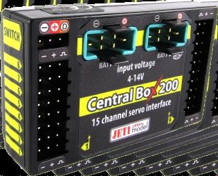
5 The Ext1 slot is also used for the firmware update connection (using the USBa). Rx1 - primary input for connecting receivers with serial output (EX bus or PPM) Rx2 - secondary (backup) input for connecting receivers with serial output (EX bus or PPM) Switch input is reserved for connecting a magnetic switch or RC switch (optional accessories). BATT1 and BATT2 MPX connectors for connecting batteries or a BEC, etc., to power the servos and receivers connected to the Central Box. RC Switch Magnetic Switch input voltage 4-14V Fig. 1: Central Box description 4
6 2.2 Central Box 100 The Central Box 100 has 8 servo outputs with overload protection, labeled 1 through 8. OUT/IN universal input/output for switching additional functions or for supervising the operational status Ext1 this port can be configured for use as: an output to connect a JETIBOX or Duplex EX receiver to either configure the Central Box or for the output of telemetry data an input for telemetry sensors The Ext1 slot is also used for the firmware update connection (using the USBa). Rx1 - primary input for connecting receivers with serial output (EX bus or PPM) Rx2 - secondary (backup) input for connecting receivers with serial output (EX bus or PPM) BATT1 MPX connector for connecting batteries or a BEC, etc., to power the servos and receivers connected to the Central Box. input voltage BATT 4-14V Rx 1 Rx 2 Out/In 8 channel servo interface 8 Fig. 2: Central Box 100 description 5 Input Voltage
7 2.3 Magnetic switch ( Central Box 200 only) The magnetic switch is used to turn the Central Box 200 on or off and is connected to a separate slot labeled Switch. To turn on the Central Box using the magnetic switch it is necessary to hold the supplied magnet carrier (key) to the target so that the carrier (key) and the target on the magnetic switch are properly oriented (align the dots). Mounting Hole Target Led On Key Fig. 3: Description of magnetic switch and the key Green LED - flashing LED signals proper detection of the magnet key - steady LED signals On state When the magnet key is held to the target in the proper orientation, the green LED glow steadily after 1 second indicating that the electronic switch is turned on. Switching off is done in a similar manner, when the magnet key is held to the target in the proper orientation, after 1 second, the green LED goes off and the system switches off. If the switch is not plugged in the Central Box, the Central Box is switched on. The system remembers whether it has been switched on or off. If the system is switched on via the magnetic switch and then the power supply is disconnected, when the batteries are re-connected to the system automatically returns to the on state. For safety reasons, always switch the system off via magnetic switch before disconnecting the power batteries. 6
8 When turning on, connect the batteries first and then turn the system on via magnetic switch. Keep the same rule when switching off. First switch the system off via magnetic switch and then disconnect the batteries. 3 Connection The Central Box is connected to the power supply, receiver, servos, controller/controllers and eventually sensors. Please follow the subsequent general guidelines about proper connection of the Central Box and these other components. 3.1 Power Supply The Central Box can be powered from batteries which are directly connected, from voltage regulators connected to batteries or via BEC. When selecting power sources for the Central Box, be sure to follow the minimum power requirements. Together, both power supplies methods must be able to supply a 15A continuous and 90A peak current. If the power source is not strong enough, the overload protection feature of the Central Box may not function correctly. The power batteries are connected to the Central Box using MPX connectors. The Central Box allows up to two batteries to be connected. During use, the power is actually supplied from the battery with the higher voltage. If the voltage is the same, the power can be used from both batteries at the same time. When the voltage of the batteries is different, the power is not shared and each pack is isolated from each other. This allows you to use batteries of different capacity, number of cells, and chemistry type. If the power for the Central Box is provided only from one battery, it can be connected via BATT1 or BATT2 input. 7
9 RC Switch Magnetic Switch Rsat2 (Rx2) Rsat2 (Rx1) SERVO standard SERVO standard Input Voltage 6V input voltage 4-14V Fig. 4: Example of the Central Box 200 powered for use with standard servos (voltage range up to 6V) SERVO standard Input Voltage 6V input voltage BATT 4-14V channel servo interface Rsat2 (Rx1) Rx 1 Rx 2 Rsat2 (Rx2) Out/In 8 Fig. 5: Example of the Central Box 100 powered for use with standard servos (voltage up to 6V) 8
10 Central Box does not contain circuitry to stabilize or regulate voltage to the servos. The level of the input voltage is equal to the level of (output) supply voltage level to the servos. Be sure to match the proper type of servos with your selected power supply. Eg. when using 2 Li-xx cells without a regulator, it is necessary to use servos labeled High Voltage. RC Switch Magnetic Switch Rsat2 (Rx2) Rsat2 (Rx1) input voltage 4-14V SERVO High Voltage SERVO High Voltage Input voltage 8.4V Fig. 6: Example of the Central Box 200 powered for use with HIGH Voltage servos Caution: It is not recommended to supply power to the Central Box through the outputs for servos, sensors or receivers. 9
11 SERVO High Voltage Rsat2 (Rx1) Input Voltage 8.4V input voltage BATT 4-14V channel servo interface Rx 1 Rx 2 Rsat2 (Rx2) Out/In 8 Fig. 7: Example of the Central Box 100 powered for use with HIGH Voltage servos 3.2 Overload protection of servos The Central Box has an overload protection circuit on every servo output. In case of an overload, the affected servo output is disconnected from the power supply while the remaining servo outputs are still powered. NO NO SERVO SERVO SERVO SERVO YES SERVO Fig. 8: Correct connection of servos to the Central Box 10
12 Caution: It is not recommended: - to connect more Central Box outputs to one servo - to use a Y cable (connecting two servos to one output) 3.3 Connecting Central Box PPM variant The receivers can be connected to the Central Box using the Rx1 and Rx2 inputs. The Ext1 port is for output of telemetry data from the Central Box in the form of EX telemetry. To use the Central Box telemetry and other sensors connected to it, use a Duplex EX receiver. Simply connect the Central Box output labeled Ext1 with the Duplex EX receiver input labeled Channels 14 and 15 can be configured as servo outputs, or as inputs for telemetry sensors ( Central Box 200 only). Configuring the Central Box is in this way done by using a JETIBOX; either directly connected to the Central Box, or wirelessly using a JETI transmitter. Input Voltage input voltage BATT 4-14V SERVO channel servo interface Rx 1 Rx 2 PPM Rsat2 (Rx1) Rsat2 (Rx2) PPM Out/In 8 Fig. 9: Block diagram of Central Box 100 connection - PPM variant 11
13 RC Switch Magnetic Switch Rsat2 (Rx1) PPM Rsat2 (Rx2) PPM SERVO Input Voltage input voltage 4-14V SERVO/Sensor SERVO Fig. 10: Block diagram of Central Box 200 connection - PPM variant 3.4 Connecting Central Box EX Bus variant Receivers can be connected to the Central Box using the Rx1 and Rx2 inputs. Ext1 is an input for telemetry sensor. Telemetry is transmitted to the receivers via EX Bus. Channels 14 and 15 can be configured as servo outputs or as inputs for connecting telemetry sensors ( Central Box 200 only). Configuring the Central Box is in this case done directly in the transmitter via EX Bus. When operating the Central Box with DC/DS transmitter, it is recommended to use two receivers communicating with the transmitter in the wireless mode "Double path". 12
14 Input Voltage 7 SERVO Rsat2 (Rx1) input voltage BATT 4-14V channel servo interface Rsat2 (Rx2) Rx 1 Rx 2 Out/In 8 Jetibox/Sensor Fig. 11: Block diagram of Central Box 100 connection - EX Bus variant RC Switch Magnetic Switch Rsat2 (Rx1) Rsat2 (Rx2) SERVO Input Voltage Jetibox/Sensor SERVO/Sensor input voltage 4-14V SERVO Fig. 12: Block diagram of Central Box 200 connection - EX Bus variant The Central Box can be configured in two ways: by JETIBOX connection (directly to the Central Box or wirelessly via the transmitter) by DC/DS transmitter via Device Explorer (EX Bus) 13
15 4 Configuration via JETIBOX The JETIBOX terminal can be used for parameter setting and retrieving data. After connecting to the Central Box (output Ext1), a startup screen appears that contains identification of the device in the first line of the JETIBOX display. The second line contains the data showing the consumed capacity of batteries 1 and 2. By pushing the R button (to the right) on the JETIBOX, you get to the expander menu. In the expander menu, the second lines display the sensors that are connected to inputs Ext1, Ext2/15 and Ext3/14. Using buttons U and D (down and up arrows) of the JETIBOX it is possible to browse through the expander inputs. The selected input is marked with a curly bracket brace after the input number, eg. 1}. By pushing the R button (right arrow) it is possible to enter a selected sensor, where you can adjust and display its parameters. Return from the sensor menu: by holding the L button (left arrow) for extended time by holding the L button (left arrow) for short time, in case you are in the basic menu of the sensor (in the first line there is identification of the sensor and in the second line there are actual data, such as MUI 30; 14,2V 7,8A ) The input marked 1} means that there is no device connected to this input or the connected device is not compatible, or the input from the Central Box is not properly configured. By pushing the D button (down), you get from the initial screen of the Central Box to its menu. 14
16 4.1 Actual values *CTRAL BOX*: Actual Value by pushing the D button (down arrow) you select the display of actual measured values Accu voltage - shows the actual voltage of both inputs Accu current - displays the actual current flowing from the battery to the output Accu capacity consumed capacity of each battery Over-I Monitor - indication of servo output; (-) output is fine (x) the output is overloaded. Outputs are ordered: Fig. 13: Description of outputs Temperature actual temperature of Central Box Information on the status of receivers - number of detected channels and the period of signal 4.2 Minimum / Maximum values *CTRAL BOX*: MIN / MAX by pushing the D button (down arrow) you select a display of extreme voltage, current, temperature, and status of the receiver, which occurred during the operation. Recorded extremes are deleted manually in the Settings menu - Erase Data. Minimal voltage the lowest voltage detected by the Central Box on the inputs during its operations Maximal voltage the highest voltage detected by the Central Box on the inputs during its operation Maximal current the highest current detected by the Central Box on the inputs during its operation 15
17 Min/Max Temper. - the highest and the lowest temperature of the Central Box during its operation (since the last manual reset) Statistics of the received signal expressed in time R1: how long was the signal from the primary receiver available to the Central Box R2: how long was the signal from the secondary receiver available to the Central Box Statistics of the received signal expressed as a percentage R1: what percentage of the total operating time was the signal from the primary receiver available to the Central Box R2: what percentage of the total operating time was the signal from the secondary receiver available to the Central Box Over-I Monitor - indication of servo output during the operating time of the Central Box; (-) output is fine (x) the output is overloaded 4.3 Setting *CTRAL BOX*: SETTING By pushing the D button (down arrow) you get to the basic setting of the device. Fail Safe switches on/off of the Fail Safe function. If the Fail Safe function is deactivated, there is no signal generated in any Central Box outputs at the signal loss. If you activate the Fail Safe function, you can also select how the Central Box responds at the signal loss for each of the individual outputs (OUT off, hold, fail safe). Signal Fault Delay the length of time from when the Central Box detects a signal loss to when the programmed Fail Safe output is performed. During this time the last servo input is held. After the selected time has elapsed, the Central Box outputs behave according to setting for each specific output. Output Period setting for the period of the output signals (default Auto-synchronous mode with the transmitter ). This parameter significantly affects the behavior of the servos. For analog servos the reaction (response) accelerates and the power 16
18 consumption is higher when the values for the output period are lower. This can lead to vibration in some servos if the values are set too low. Erase data by pushing the arrows R and L (right and left) together, the minimum and maximum are reset, see "MIN / MAX Minimum / Maximum". Shutdown Voltage - input voltage level at which the Central Box automatically turns off. If Central Box evaluates the input voltage is lower than the stop level for more than 60 seconds, it automatically turns off. 4.4 Out Pin Set *CTRAL BOX*: Out Pin Set pushing the D button (down arrow) moves you to basic settings of particular outputs of the Central Box. Set Output pin -selection of the slot that will be used for the following settings. In this menu the output deflection of the selected output is displayed as a percentage. Y1 is the Central Box output labeled 1, Y2 is the Central Box labeled 2, etc. Function setting of alternative functions of the outputs. This function is available for outputs: Central Box 200 Y14 and Y15: Servo Output function or Telemetry Input. EXT1: Telemetry Input function or JETIBOX Central Box 100: EXT1: Telemetry Input function or JETIBOX SetInChannel assigns the input channel (marked as Chx) to a specific output (marked as Yx) Reverse reverses the output direction Signal Fault - setting behavior of the receiver in case of signal loss hold - repeats the last valid deflection command before signal loss out off does not generate any signal for servo in case of signal loss FailSafe transition to preset deflection of individual outputs 17
19 FS position setup of the selected output deflection in case of signal loss FS speed setup for how quickly the output transitions to its programmed deflection in case of signal loss ATV High Limit Yx sets the upper travel (throw) limit of the output ATV Low Limit Yx sets the lower travel (throw) limit of the output Output Trim setting the neutral deflection of the receiver output Output Group setting the output to a selected group of output pulses that will be generated from the receiver at the same time 4.5 Alarms *CTRAL BOX*: Alarms pushing the D button (down arrow) moves you to the menu for setting the alarms. If the alarm is set to OFF, the alarm is deactivated. Capacity Alarm - level of the capacity taken from the battery at which the alarm will sound Current Alarm - level of current drawn from the battery at which the alarm will sound Voltage Alarm if the battery voltage drops below this level, the alarm will sound Short Circuit Alarm - Activating/deactivating the alarm for when the outputs are overloaded Temperature Alarm Activating/deactivating alarms for the Central Box overheating 18
20 4.6 Service information *CTRAL BOX*: SERVICE pushing the D button (down arrow) moves you to the display of the firmware version and the menu for restoring the default settings of the Central Box. PresetToSetup pushing arrows R and L (right and left) together leads to loading the default settings of the Central Box. CBOXxxx v. xx.xx ID xxxxx:xxxxx designation of the product with the firmware version and the serial number (ID) 19
21 5 Configuration via the DC/DS transmitter The Central Box can be configured by a DC/DS transmitter via the Device Explorer menu. It is necessary to follow these rules for configuring the Central Box via transmitter: - Receiver firmware version Duplex 3.12 and newer (with setting Output mode->ex Bus) - The receiver must be connected to the Central Box via EX bus - Transmitter firmware version 2.02 and newer + the device profile (CBOX100.bin or CBOX200.bin) recorded in the devices directory on the SD card of the transmitter When everything is properly connected and configured, the CBOX100 or CBOX200 item appears in the Device Explorer menu. Entering the item moves you to the configuration menu. Fig. 14: Device Explorer 20
22 5.1 General Settings Output Period setting for the period of the output signals (default Auto-synchronous mode with the transmitter). This parameter significantly affects the behavior of the servos. For analog servos the reaction (response) accelerates and the power consumption is higher when the values for the output period are lower. This can lead to vibration in some servos if the values are set too low. For Cental Box 200: Ext1, Ext3/Pin14, Ext2/Pin15 setting of alternative output functions. JETIBOX output for connecting JETIBOX, eventually EX telemetry Telemetry Input input for connecting telemetry sensor Servo output servo output For Cental Box 100: Ext1 setting of alternative output functions. JETIBOX output for connecting JETIBOX, eventually EX telemetry Telemetry Input input for connecting telemetry sensor Shutdown voltage - input voltage level at which the Central Box automatically turns off. If Central Box measures that the input voltage is lower than the stop level for more than 60 seconds, it automatically turns itself off. Fig. 15: Device Explorer-General Settings 21
23 5.2 Fail-Safe Fail Safe switches on/off the Fail Safe function. If the Fail Safe function is deactivated, there is no signal generated in any Central Box outputs at the signal loss. If you activate the Fail Safe function, you can also select how the Central Box responds at signal loss for each of the individual outputs (OUT off, hold, fail safe).. Signal Fault Delay the length of time from when the Central Box detects a signal loss to when the programmed Fail Safe output is performed. During this time the last servo input is held. After the selected time has elapsed, the Central Box outputs behave according to setting for each specific output. Mode - fail-safe mode for specific output of the Central Box Hold: repeats the last valid deflection command before signal loss Out OFF: does not generate any signal for a servo in case of signal loss Fail-Safe: generates pre-set deflection (Value) at the failure with slowdown (Speed) For easier setup the Fail-Safe deflection can be immediately applied to the Central Box output if the cursor is on the menu item Value and you press the function key F4 (Apply). Fig. 16: Device Explorer-Fail Safe 22
24 5.3 Servo Output Mapping Servo No. assigning outputs of the transmitter to the Central Box outputs (Output pin). Group assigns specific output to the group of output impulses that will be generated from the receiver in the same time Fig. 17: Device Explorer-Servo Output Mapping 5.4 Telemetry Temp. actual temperature of the Central Box Shorted outputs No. actual number of overloaded outputs Voltage actual voltage of individual outputs of the Central Box Current actual current drawn from the battery Capacity capacity taken from the batteries Fig. 18: Device Explorer-Telemetry 23
25 5.5 Telemetry Min/Max Clear Min/Max switch here you can assign a control (switch, stick or knob) on the DC/DS transmitter which clears the recorded battery capacity and minimum/maximum values in the Central Box. Clear Now allows you to immediately clear the recorded battery capacity and minimum/maximum values in the Central Box. For description of individual items, see the chapter Minimum/Maximum values Fig. 19: Device Explorer-Telemetry Min/Max 5.6 Reset to factory settings Reset to factory settings reset to factory setting of the Central Box 24
26 6 Firmware update Either Central Box allows firmware update via a PC. The update is performed using the JETI USBa. The procedure is as shown below: On the manufacturer/distributor internet pages ( under Downloads, you will find an update program with the most recent firmware. Download it to your PC. 1. Connect the Central Box output labeled Ext1 with the USB adapter by means of interconnection cable. 2. Start the firmware update program for the Central Box on your PC. 3. For Central Box 100: Connect the Central Box to the power supply. For Central Box 200: Switch on the Central Box using the magnetic switch or the RC switch. The USB-adapter driver installation instructions can be found in the USB-adapter instruction booklet. RC Switch Magnetic Switch PC Power supply USB adapter USBa input voltage 4-14V 25

27 Power supply PC input voltage BATT 4-14V channel servo interface Rx 1 Rx 2 USB adapter Out/In 8 USBa 7 Safety precautions for working with magnets Because the Central Box 200 is put into operation via magnet, it is necessary to follow safety precautions for handling magnets. The magnet is mounted in a hard aluminum carrier. 1. Keep the magnetic key a safe distance from all devices that could be damaged by the magnet, such as TV, credit cards, computers, etc. The magnet may interfere with the function of pacemakers! 2. Keep magnets away from children because of the danger of swallowing or pinching! 26
28 8 Technical specifications of the Central Box Technical specifications of the Central Box 100 Recommended input voltage Number of connectable accu cells Continuous current Output pulse current Number of servo outputs Operating temperature Weight Dimensions 4 14 V 2-3 LiXX or 4-10 NiXX 10 A 90 A up to 8-20 C up to +75 C 20 g 52x25x11 mm Technical specifications of the Central Box 200 Recommended input voltage Number of connectable accu cells Continuous current Output pulse current Number of servo outputs Consumption in the off state with magnetic switch Consumption on the off state with the RC switch Operating temperature Weight Dimensions Dimensions of magnetic switch 4 14 V 2-3 LiXX or 4-10 NiXX 15 A 90 A up to uA 140 ua - 20 C up to +75 C 30 g 63x38x17mm 30x21x5 mm 27
29 9 Warranty, service and the technical support Warranty and service This product is covered by warranty for 24 months after the day of purchase provided that it has been operated in accordance with these instructions at the specified voltage and is not mechanically damaged. When claiming warranty repairs for the product, always attach a proof of purchase. Warranty and post-warranty service is provided by your dealer or the manufacturer. Technical support In case you are not sure about the setup or some functions of the product, do not hesitate to contact our technical support. You can contact either your dealer, or directly the manufacturer JETI model s.r.o.. For further information see our webpages We wish you sucessful flying with the products of: JETI model s.r.o. Příbor, 28

30 Declaration of Conformity Issues name & addres: JETI model s.r.o. Lomena 1530, Pribor Object of the declaration: Products: Servo interface Trade name: Central Box Model: Central Box 100, 200 Country of origin: Czech republic The object of declaration described above is in conformity with the requirements of the folowing EU legislations and harmonized standards: ČSN :2007, ČSN :2007+A1:20011 Electromagnetic compatibility: / /2008 Signed for and on behalf of: Tomáš Klesnil production Manager 29

31 30
32 JETI model s.r.o. Lomená 1530, Příbor Czech Republic
MVario2. MVario2. System that measures atmospheric pressure. EN User Manual
 MVario2 System that measures atmospheric pressure User Manual English 1. Description and function... 03 1.1 The main function... 03 1.2 Technical data... 04 2. Placement and connection... 05 2.1 Placement
INSTRUCTION MANUAL DUAL SWITCH MIXER DSM ESC
 INSTRUCTION MANUAL DUAL SWITCH MIXER DSM ESC By JETI model s.r.o. 19. 2. 2015 Contents 1. Introduction... 3 2. DSM ESC Circuitry... 3 3. Magnetic Switch Control... 4 4. Installation... 5 5. Magnet Handling
Xtreme Power Systems
 Xtreme Power Systems XtremeLink NANO RECEIVER Installation And Usage Manual XtremeLink is a registered trademark of Xtreme Power Systems, LLC. Firmware v 1.9 Manual v 1.9 Revision Date: November 11 th,
Manual Electric Air-Module 2-14 S with Vario Graupner HoTT 2.4
 Manual 33620 Electric Air-Module 2-14 S with Vario Graupner HoTT 2.4 CONTENTS: 1. Description... 01 2. Mounting the module in the plane... 01 3. Quick Guide... 02 3.1. Connection of sensors... 03 4. Starting
DragonLink Advanced Transmitter
 DragonLink Advanced Transmitter A quick introduction - to a new a world of possibilities October 29, 2015 Written by Dennis Frie Contents 1 Disclaimer and notes for early release 3 2 Introduction 4 3 The
DXXX Series Servo Programming...9 Introduction...9 Connections HSB-9XXX Series Servo Programming...19 Introduction...19 Connections...
 DPC-11 Operation Manual Table of Contents Section 1 Introduction...2 Section 2 Installation...4 Software Installation...4 Driver Installastion...7 Section 3 Operation...9 D Series Servo Programming...9
Manual for Hyperion Receivers 1. Binding Step 1. Power up the receiver in bind mode
 - This is not a Horizon Hobbies DSM2, DSMX product, and is not manufactured or endorsed by Horizon Hobbies LLC. DSM2, and DSMX are registered trademarks of Horizon Hobbies LLC. Manual for Hyperion Receivers
electronics for models CATALOGUE 2008/2009
 electronics for models CATALOGUE 2008/2009 The DUPLEX system is primarily designed for the full range operation of radio control models. DUPLEX operates in the 2,4 GHz band. DUPLEX is not a traditional
RC Camera Control. User Guide v1.3 (RCCC v1.1) 11/7/2012
 11/7/2012") RC Camera Control User Guide v1.3 (RCCC v1.1) 11/7/2012 kristaps_r@rcgroups INTRODUCTION RC Camera Control board (RCCC) is multifunctional control board designed to for aerial photography or First Person
RC Camera Control User Guide v1.3 (RCCC v1.1) 11/7/2012 kristaps_r@rcgroups INTRODUCTION RC Camera Control board (RCCC) is multifunctional control board designed to for aerial photography or First Person
Copyright Graupner/SJ GmbH. Manual. mz-4 2 channel HoTT 2,4 GHz transmitter No. S1031
 Copyright Graupner/SJ GmbH EN Manual mz-4 2 channel HoTT 2,4 GHz transmitter No. S1031 Index Introduction... 4 Service Centre... 4 Intended use... 5 Package content... 5 Technical Data... 5 Symbols Explication...
Introduction. Overview. Outputs Normal model 4 Delta wing (Elevon) & Flying wing & V-tail 4. Rx states
 & Flying wing & V-tail 4. Rx states") Introduction Thank you for purchasing FrSky S6R/S8R (SxR instead in this manual) multi-function telemetry receiver. Equipped with build-in 3-axis gyroscope and accelerometer, SxR supports various functions.
Introduction Thank you for purchasing FrSky S6R/S8R (SxR instead in this manual) multi-function telemetry receiver. Equipped with build-in 3-axis gyroscope and accelerometer, SxR supports various functions.
computer radio control system COMPLEX RADIO CONTROL SYSTEM Receivers REX
 COMPLEX RADIO CONTROL SYSTEM User Manual Receivers REX FW 1.05 1. Introduction... 04 2. Technical data... 05 2.1 Properties... 06 2.2 Important Notices... 06 3. Installation... 08 3.1 Installation in the
AA-35 ZOOM. RigExpert. User s manual. Antenna and cable analyzer
 AA-35 ZOOM Antenna and cable analyzer RigExpert User s manual . Table of contents Introduction Operating the AA-35 ZOOM First time use Main menu Multifunctional keys Connecting to your antenna SWR chart
Industriefunkuhren. Additional Technical Manual. for Board 7271 with Option FG7271/PPM (Output of Minute Pulses) ENGLISH. Version:
 ENGLISH. Version:") Industriefunkuhren Additional Technical Manual for Board 7271 with Option FG7271/PPM (Output of Minute Pulses) ENGLISH Version: 01.00-13.01.2009 Base Description NTP/SINEC H1 LAN Board Model 7271 Version:
Industriefunkuhren Additional Technical Manual for Board 7271 with Option FG7271/PPM (Output of Minute Pulses) ENGLISH Version: 01.00-13.01.2009 Base Description NTP/SINEC H1 LAN Board Model 7271 Version:
Power Meter. Measurement Guide. for Anritsu RF and Microwave Handheld Instruments BTS Master Site Master Spectrum Master Cell Master
 Measurement Guide Power Meter for Anritsu RF and Microwave Handheld Instruments BTS Master Site Master Spectrum Master Cell Master Power Meter Option 29 High Accuracy Power Meter Option 19 Inline Peak
SV613 USB Interface Wireless Module SV613
 USB Interface Wireless Module SV613 1. Description SV613 is highly-integrated RF module, which adopts high performance Si4432 from Silicon Labs. It comes with USB Interface. SV613 has high sensitivity
RigExpert AA-170 Antenna Analyzer (0.1 to 170 MHz) User s manual
 User s manual") RigExpert AA-170 Antenna Analyzer (0.1 to 170 MHz) User s manual Table of contents 1. Description... 3 2. Specifications... 4 3. Precautions... 5 4. Operation... 6 4.1. Preparation for use... 6 4.2. Turning
RigExpert AA-170 Antenna Analyzer (0.1 to 170 MHz) User s manual Table of contents 1. Description... 3 2. Specifications... 4 3. Precautions... 5 4. Operation... 6 4.1. Preparation for use... 6 4.2. Turning
Copyright Graupner/SJ GmbH. Manual. mz-4 2 channel HoTT 2,4 GHz transmitter No. S1031
 Copyright Graupner/SJ GmbH EN Manual mz-4 2 channel HoTT 2,4 GHz transmitter No. S1031 Index Introduction... 4 Service Centre... 4 Intended use... 5 Package content... 5 Technical Data... 5 Symbols explication...
Astra-R Kit Wireless Alarm System Operation Manual
 Astra-R Kit Wireless Alarm System Operation Manual This operation manual describes principles of functioning, proper use, maintenance and service for the wireless alarm system Astra- R Kit (Figure 1).
EE-110 Introduction to Engineering & Laboratory Experience Saeid Rahimi, Ph.D. Labs Introduction to Arduino
 EE-110 Introduction to Engineering & Laboratory Experience Saeid Rahimi, Ph.D. Labs 10-11 Introduction to Arduino In this lab we will introduce the idea of using a microcontroller as a tool for controlling
3. WHEN TO TURN ON. Always turn the Tx on first, unless binding. Always turn Rx off first.
 - 2 - IF PICS ARE NOT CLEAR ENOUGH, PLEASE DOWNLOAD AND PRINT OUT https://www.rcs-rc.com/store/pdf/instructions/receivers/rx102-1(ab)lr.pdf 2. FEATURES. Purpose: Rx102-1(AB)LR Live Steam & Low OFF Batt
instruction manual for Open LRS New Generation
 instruction manual for Open LRS New Generation Table of contents 1. Important warnings 2. Hardware Overview 3 2.1 DTF UHF 4 Channel 4 2.2 HobbyKing RX 5 3. Instructions 3.1 Basic functions 6 3.2 Flashing
LED Driver Compact dimming
 Driver LCAI 35W 3mA 900mA ECO C flat ECO series Product description Dimmable built-in LED Driver for LED Constant current LED Driver Output current adjustable between 3 900 ma Max. output power 35 W Nominal
Manual. GR-16 HoTT 2.4 GHz 8 channel receiver. No Copyright Graupner/SJ GmbH
 EN Manual GR-16 HoTT 2.4 GHz 8 channel receiver No. 33508 Copyright Graupner/SJ GmbH 2 / 16 Index Introduction... 4 Service centre... 4 Intended use... 5 Target group...5 Package content... 5 Technical
Smart Bus RRS. Quick Start Guide
 Smart Bus RRS Quick Start Guide Thank you for your purchase of the Advance Radio Smart Bus. In this quick start guide we will show you how to connect your new Smart Bus, General use and Set Up. Please
PHASED OUT. LED Driver Linear / area dimming. Driver LCAI 20W 150mA 400mA ECO lp ECO series
 EL Product description Dimmable built-in LED Driver for LED Constant current LED Driver Output current adjustable between 150 400 ma Max. output power 20 W Nominal life-time up to 100,000 h 5-year guarantee
YGE ProgCard II - Programming Card
 YGE ProgCard II - Programming Card With the programming card, we offer an easy to use programming unit, with which all our ProgCard II capable speed controllers can have their individual functions changed.
Brunata Optuna H Ultrasonic energy meter Type 775 Installation Guide Edition 1.2
 Ultrasonic energy meter Type 775 Installation Guide Edition 1.2 UK-QB101575 / 29.05.2012 Brunata a/s is a Danish owned company. We have more than 90 years of experience within developing and producing
Scorpion HX User Manual R/C Version
 Table of Contents Features...3 Connections...5 Setup...5 Setup Complete...10 Status Codes...11 Mounting your Scorpion...12 Notes on PCM radios...12 Service and Support...13 Limitations and Warrantees...13
SGD-EEM «MEDUSA» GEOELECTRICAL MULTIFUNCTION RECEIVER
 Research and Production Company Sib Geofiz Pribor SGD-EEM «MEDUSA» GEOELECTRICAL MULTIFUNCTION RECEIVER Version V2.2 OPERATIONS MANUAL 2012 2 Operation Manual Sib Geofiz Pribor SGD-EEM «MEDUSA» 3 CONTENTS
GR-12, GR-16, GR-24 and GR-32 HoTT 6, 8, 12 and 16 channel 2.4 GHz HoTT receiver No , 33508, and 33516
 EN Manual GR-12, GR-16, GR-24 and GR-32 HoTT 6, 8, 12 and 16 channel 2.4 GHz HoTT receiver No. 33506, 33508, 33512 and 33516 Copyright Graupner/SJ GmbH 2 / 24 Table of content Introduction...4 Service
Manual. GR-12 HoTT 2.4 GHz 6 channel receiver. No Copyright Graupner/SJ GmbH
 EN Manual GR-12 HoTT 2.4 GHz 6 channel receiver No. 33506 Copyright Graupner/SJ GmbH 2 / 16 Index Introduction... 4 Service centre... 4 Intended use... 5 Target group...5 Package content... 5 Technical
HZJF-9007 Fully Functional Partial Discharge Inspector USER MANUAL. Huazheng Electric Manufacturing(Baoding) Co.,Ltd
 Co.,Ltd") HZJF-9007 Fully Functional Partial Discharge Inspector USER MANUAL Huazheng Electric Manufacturing(Baoding) Co.,Ltd Safety Terms and Symbols This manual may contain the terms: Warning! Indicate the conditions
HZJF-9007 Fully Functional Partial Discharge Inspector USER MANUAL Huazheng Electric Manufacturing(Baoding) Co.,Ltd Safety Terms and Symbols This manual may contain the terms: Warning! Indicate the conditions
GFL-1000 User Manual Ground Fault Locator
 GFL-Series User Manual V1.1 GFL-1000 User Manual Ground Fault Locator Contents Contents... 1 1 Declaration of Conformity... 3 2 Introduction... 3 3 Equipment Information... 3 3.1 Safety Precautions...
PHASED OUT. LED Driver Linear / area dimming. Driver LCAI 20W 350mA 550mA ECO lp ECO series
 Product description Dimmable built-in LED Driver for LED Constant current LED Driver Output current adjustable between 350 550 ma Max. output power 20 W Nominal life-time up to 100,000 h 5-year guarantee
CX-1X Mini Heading-Hold Gyro System. Copyright 2014 KY MODEL Company Limited.
 CX-1X2000 Mini Heading-Hold Gyro System INSTRUCTION MANUAL www.copterx.com Copyright 2014 KY MODEL Company Limited. MENU 1. 2. 3. 4. 5. 6. 7. 8. 9. 10. Table of content Introduction Features Specifications
LED Driver Linear / area dimming. Udriver LCAI 20W 350mA 550mA ECO lp ECO series
 Udriver LCAI 20W 350mA 550mA ECO lp ECO series Product description Dimmable built-in LED Driver for LED Constant current LED Driver Output current adjustable between 350 550 ma Max. output power 20 W Nominal
Castle Multi-Rotor ESC Series User Guide
 Castle Multi-Rotor ESC Series User Guide This user guide is applicable to all models of Castle Multi-Rotor ESC. Important Warnings Castle Creations is not responsible for your use of this product or for
EzOSD Manual. Overview & Operating Instructions Preliminary. April ImmersionRC EzOSD Manual 1
 EzOSD Manual Overview & Operating Instructions Preliminary. April 2009 ImmersionRC EzOSD Manual 1 Contents Overview... 3 Features... 3 Installation... 3 1. Installation using an ImmersionRC camera and
CX-PB Program Box for CopterX Gyro. Copyright 2011 KY MODEL Company Limited.
 CX-PB001 Program Box for CopterX Gyro INSTRUCTION MANUAL www.copterx.com Copyright 2011 KY MODEL Company Limited. MENU 1. 2. 3. 4. 5. 6. Table of content Introduction Specifications Buttons and Connections
LED Driver Compact dimming
 Driver LCAI 35W 350mA 900mA ECO C ECO series Product description Dimmable built-in LED Driver for LED Constant current LED Driver Output current adjustable between 350 900 ma Max. output power 35 W Nominal
VFSC9 ELECTRONIC SPEED CONTROLLER. Mounting and operating instructions
 ELECTRONIC SPEED CONTROLLER Mounting and operating instructions Table of contents SAFETY AND PRECAUTIONS 3 PRODUCT DESCRIPTION 4 ARTICLE CODES 4 INTENDED AREA OF USE 4 TECHNICAL DATA 4 STANDARDS 5 WIRING
Xtreme Power Systems X24. Integrated Flight Control System. Installation And Usage Manual
 Xtreme Power Systems X24 Integrated Flight Control System Installation And Usage Manual Supports: XtremeLink RFU and Nano receivers Futaba SBUS and SBUS2 receivers Spektrum DSM2/DSMX satellite receivers
OVEN INDUSTRIES, INC. Model 5C7-362
 OVEN INDUSTRIES, INC. OPERATING MANUAL Model 5C7-362 THERMOELECTRIC MODULE TEMPERATURE CONTROLLER TABLE OF CONTENTS Features... 1 Description... 2 Block Diagram... 3 RS232 Communications Connections...
Relay Driver Overview and Applications
 Relay Driver Overview and Applications Describes Basic and Advanced Settings for common and alternative/novel uses for the Relay driver (RD-1). Morningstar s Relay Driver (RD-1) is a fully programmable
A3 Pro INSTRUCTION MANUAL. Oct 25, 2017 Revision IMPORTANT NOTES
 A3 Pro INSTRUCTION MANUAL Oct 25, 2017 Revision IMPORTANT NOTES 1. Radio controlled (R/C) models are not toys! The propellers rotate at high speed and pose potential risk. They may cause severe injury
LED Driver Linear / area dimming
 EL Udriver LCAI 35W 900mA 1750mA ECO lp ECO series Product description Dimmable built-in LED Driver for LED Constant current LED Driver Output current adjustable between 900 1,750 ma Max. output power
SECTION WIRELESS CLOCK/TONE GENERATOR SYSTEM
 SECTION 13805 WIRELESS CLOCK/TONE GENERATOR SYSTEM PART 1 GENERAL 1.01 SUMMARY A. Section Includes: Satellite based, synchronized wireless clock/tone generator system, including clocks, tone generator,
Mounting Instruction. Compact Mini EGC Amplifier and Application
 Mounting Instruction Compact Mini EGC Amplifier 93230 and 93240 Application The Compact Mini EGC Amplifier type 93230 and type 93240 has one active output and is mainly used as distribution amplifier.
Ultimate Actuator Drivebox 30A Quick start guide
 2016 Ultimate Actuator Drivebox 30A Quick start guide info@e-tronix.cz e-tronix s.r.o. 1.1.2016 OBSAH Identification... 3 Serial Number... 3 Manufacturer and reseller contact... 4 Before Start... 4 UAD30A
FOD Transmitter User s Guide
 FOD Transmitter User s Guide Rev 4, 07/18/2013 AVID Technologies, Inc. FOD Transmitter User s Guide Page 2 General Description The AVID FOD (Foreign Object Detection) Transmitter is a standard WPC Qi V1.1
DPC-10. DPC-10 Software Operating Manual. Table of Contents. Section 1. Section 2. Section 3. Section 4. Section 5
 Table of Contents Section 1 Section 2 Section 3 Section 4 Section 5 About the Software Test Function Programming Functions Connections Basic Mode Connection RC Mode Connection Using the DPC-10 Test Functions
EdvoCycler & MegaCycler
 Operation Manual: EdvoCycler & MegaCycler Cat. #541 and #542 Features: 25 x 0.2 ml Tube Block (EdvoCycler) 49 x 0.2 ml Tube Block (MegaCycler) Heated Oil-Free Lid with Magnetic Latch Vivid 7 Line LCD Display
ECI 6D. Balanced Integrated Amplifier. Owner's Manual. (with a built-in DAC) ENGLISH
 ENGLISH") ECI 6D Balanced Integrated Amplifier (with a built-in DAC) Owner's Manual EN ENGLISH Unpacking the ECI 6D Immediately upon receipt of the ECI 6D, inspect the carton for possible damage during shipment.
ECI 6D Balanced Integrated Amplifier (with a built-in DAC) Owner's Manual EN ENGLISH Unpacking the ECI 6D Immediately upon receipt of the ECI 6D, inspect the carton for possible damage during shipment.
FOD Transmitter User s Guide
 FOD Transmitter User s Guide Rev 5, 05/21/2014 AVID Technologies, Inc. FOD Transmitter User s Guide Page 2 General Description The AVID FOD (Foreign Object Detection) Transmitter is a standard WPC Qi V1.1
Jet Central Sequencer Plus
 Jet Central Sequencer Plus Features The Jet Central Sequencer Plus is a multipurpose electronic device, the capabilities of the unit include: Three part sequencer, operating landing gear and two independent
PHASED OUT. LED Driver Compact fixed output. Driver LCI 20W 350mA 900mA TOP C TOP series
 EL Product description Fixed output built-in LED Driver Constant current LED Driver Output current settable 30 900 ma Max. output power 20 W Nominal life-time up to 100,000 h For luminaires of protection
Table of Contents 1 Introduction Overview Package Contents Specifications Software Updates Changelog
 DRAFT ONLY Table of Contents 1 Introduction 4 1.1 Overview 4 1.2 Package Contents 5 1.3 Specifications 5 1.4 Software Updates 6 1.4.1 Changelog 6 1.4.2 Known Issues and Limitations 6 1.5 Product Support
433MHz LRS Adjustable TX/RX Set 100mW-2000mW
 433MHz LRS Adjustable TX/RX Set 100mW-2000mW 433 Transmitter ports: GND TX (For software update: connect to USB RX) RX (For software update: connect to USB TX) PWM input (connect to 2.4GHz radio controller,
LED Driver Constant voltage
 Driver LCA 15W 24V one4all SC PRE PREMIUM series Product description Dimmable 24 V constant voltage LED Driver for flexible constant voltage stripes One4all interface and ready2mains enable different dimming
PHASED OUT. LED Driver Compact fixed output. Driver LCI 10W 150mA 400mA TOP C TOP series. Product description
 Product description EL Fixed output built-in LED Driver Constant current LED Driver Output current settable 15 4 ma Max. output power W Nominal life-time up to, h For luminaires of protection class I and
"Terminal RG-1000" Customer Programming Software. User Guide. August 2016 R4.3
 "Terminal RG-1000" Customer Programming Software User Guide August 2016 R4.3 Table of Contents Table of Contents Introduction 2 3 1.1 Software installation 3 1.2 Connecting the RG-1000 GATEWAYs to the
Instruction also available on
 TERA Radon Program EN TCR3 Central Unit Technical Specifications & Operation Manual v.2 2016 Table of Contents 1 Introduction...2 2 Description and Utilization...2 3 Scope of Delivery...4 4 Product Specification...5
Changing settings in the BlueSolar MPPT Charge Controllers
 2016-11-21 07:40 1/14 Changing settings in the BlueSolar MPPT Charge Controllers Changing settings in the BlueSolar MPPT Charge Controllers DEPRECATED: Use VictronConnect instead of mpptprefs We recommend
Using the 9XR Pro for More than Eight Channels
 Appendix B Using the 9XR Pro for More than Eight Channels Introduction In stock form, with a module such as the FrSky DJT or OrangeRx DSMX/DSM2 installed, the Turnigy 9XR Pro transmitter can control a
MMS TESTER FG320 OPERATING INSTRUCTIONS. valid from 11/2017. Machine Monitoring Systems
 Machine Monitoring Systems MMS TESTER FG320 OPERATING INSTRUCTIONS valid from 11/2017 PROFESS, spol. s r.o., Květná 5, 326 00 Plzeň Tel: 377 454 411, 377 240 470 Fax: 377 240 472 E-mail: profess@profess.cz
Smart Bus RRS. Quick Start Guide
 Smart Bus RRS Quick Start Guide Thank you for your purchase of the Advance Radio Smart Bus RRS. In this quick start guide we will show you how to connect your new Smart Bus, General use and Set Up. Please
NEULOG PHOTO GATE LOGGER SENSOR GUIDE
 NeuLog photo gate logger sensor NUL-209 Part# NL-2090 The NeuLog photo gate sensor can be used for any science experiment which involves taking accurate velocity and/or acceleration measurements especially
PHASED OUT. LED Driver Compact dimming. Driver LCAI 20W 350mA 900mA ECO SR ECO series
 Product description Independent dimmable LED Driver Constant current LED Driver Output current adjustable between 350 900 ma Max. output power 20 W Nominal life-time up to 100,000 h 5-year guarantee Dimming
NEULOG PHOTO GATE LOGGER SENSOR GUIDE
 NeuLog photo gate logger sensor NUL-209 The NeuLog photo gate sensor can be used for any science experiment which involves taking accurate velocity and/or acceleration measurements especially in the field
PHASED OUT. LED Driver Compact dimming. Driver LCAI 55W 900mA 1750mA ECO C ECO series
 Product description Dimmable built-in LED Driver for LED Constant current LED Driver Output current adjustable between 900 1,750 ma Max. output power 55 W Nominal life-time up to 100,000 h 5-year guarantee
3050 Stereo Power Amplifier
 3050 Stereo Power Amplifier Owners Manual 10/26/2016 Boulder Amplifiers, Inc. 255 Taylor Ave. Louisville, CO 80027 (303) 449-8220 www.boulderamp.com Fault Conditions Boulderlink Appendix Remote Control
Instructions for Crack Series / Superior RX
 Instructions for Crack Series / Superior RX DSMX and DSM2 Compatibility Superior Rx receivers work with both DSM2 and DSMX versions. DSMX is a development of the earlier DSM2 specification that includes
TEAM DIGITAL. SC82 Servo Controller
 TEAM DIGITAL SC Servo Controller Improving the world of DCC > DCC compatible accessory decoder > Control servos motors > Output status LEDs > inputs for turnout control > 6 inputs for semaphore signaling
PHASED OUT. LED Driver Compact fixed output. Driver LCI 10W 350mA 900mA TOP C TOP series
 EL Product description Fixed output built-in LED Driver Constant current LED Driver Output current settable 35 9 ma Max. output power W Nominal life-time up to, h For luminaires of protection class I and
Installation & User Manual Radio Remote RCS-10E
 Installation & User Manual Radio Remote RCS-10E SLEIPNER MOTOR AS P.O. Box 519 N-1612 Fredrikstad Norway Tel: +47 69 30 00 60 Fax: +47 69 30 00 70 www.side-power.com sidepower@sleipner.no Made in Norway
WIRELESS Energy Monitor - Smart Meter
 Energy saving made simple MONITOR CONTROL SAVE WIRELESS Energy Monitor - Smart Meter Monitors your electricity use and cost in real time Instruction Manual EW4500 IMPORTANT Please retain your Instruction
PLA 33. Power line analyzer. User and service manual. version 2.4
 PLA 33 Power line analyzer User and service manual version 2.4 Content. Front control panel and terminal plate...3 7.2.2. System frequency setting...0 2. Device description...4 7.2.3. Password protection...0
Multi-protocol decoder with Load Regulation for Locomotives with 21-way connector
 Multi-protocol decoder with Load Regulation for Locomotives with 2-way connector Features Locomotive Decoder Multi-protocol decoder with load regulation for DCC and Motorola Suitable for DC and Bell armature
basicdim Wireless basicdim Wireless LED Drivers
 LED Drivers Driver LC 35W 24V bdw SC PRE2 premium series constant voltage Product description Dimmable 24 V constant voltage LED Driver for flexible constant voltage strips enables different dimming options
Dual-band radio transmitter T10, Т10С T10U, T10UC
 Dual-band radio transmitter T10, Т10С T10U, T10UC (v.yymmdd) Installation manual www.trikdis.com 1 Contents Safety requirements... 3 Transmitter function... 3 Operation... 3 Outside view... 4 Installation...
computer radio control system CZECH REPUBLIC DC/DS GHz/900MHz Dual Band System FW 4.10
 CZECH REPUBLIC DC/DS-24 2.4GHz/900MHz Dual Band System FW 4.10 1. Introduction... 07 3.3.5 Throttle stick travel adjustment... 16 1.1 DC/DS...07 3.3.6 Changing the transmitter mode... 16 1.2 Features...
Instruction. INFOCAL 8 Energy calculator. 1.0 Table of contents. 2.0 Safety notes and product information
 Instruction INFOCAL 8 Energy calculator 1.0 Table of contents 1.0 Table of contents...1 2.0 Safety notes and product information...1 3.0 Installation of energy calculator...2 4.0 Installation of temperature
BMS BMU Vehicle Communications Protocol
 BMS Communications Protocol 2013 Tritium Pty Ltd Brisbane, Australia http://www.tritium.com.au 1 of 11 TABLE OF CONTENTS 1 Introduction...3 2 Overview...3 3 allocations...4 4 Data Format...4 5 CAN packet
Synchroniser Relay SYN-7
 Synchroniser Relay SYN-7 1/19 Index 1 General Remarks...3 2 Operating Principle...3 2.1 Isolated Operation (Firmware Version V1.14 or higher)...4 2.2 Usage as a locking Relay...4 2.3 Switching onto Dead
BandMaster V Manual. Installation
 BandMaster V Manual Installation Installing and configuring the BM-5 BandMaster V is a simple process. All the configuration process is done from the front panel. Installation and configuration steps are
Revision 1. March 21, ADC Operation Manual N 11 th St San Jose CA
 Revision 1 March 21, 2017 ADC Operation Manual www.mountztorque.com - 1080 N 11 th St San Jose CA 95112 408.292.2214 1 Index 1. Installation 3 1.1 Required PC specification 3 1.2 Software 3 2. Operation
REFERENCE AIRBASS Wireless Subwoofer Volume Control System
 REFERENCE AIRBASS Wireless Subwoofer Volume Control System This device complies with F.C.C. Rules part 15. Operation is subject to the following two conditions: (1) This device may not cause harmful interference
M O D U L E - 7 D Model CS-CAL/DLIU V6.0 Operator s Manual
 O P E R A T I O N S A N D P R O C E D U R E S F O R C S - C A L / D L I U V 6. 0 A N D A C C E S S O R I E S Model CS-CAL/DLIU V6.0 Visual screen display allows easy step-by-step operation Rechargeable
LED Driver Compact fixed output
 w LED Driver Driver LCI 100W 900mA 1750mA TOP C TOP series Product description Fixed output built-in LED Driver Constant current LED Driver Output current settable 900 1,750 ma Max. output power 100 W
Hub and Cluster. ogramming Manual. Pro MAN3090
 Hub and Cluster Pro ogramming Manual MAN3090 Contents Introduction 3 Radio Channels 28 System Overview 3 Currently Used 30 RCC RCC Ch 30 System Design 4 Device RCC Ch 30 Manual Select 30 Compatibility
Caution Notes. Features. Specifications. Installation. A3-L 3-axis Gyro User Manual V1.0
 Caution Notes Thank you for choosing our products. If any difficulties are encountered while setting up or operating it, please consult this manual first. For further help, please don t hesitate to contact
EXMITTER -- Professional Remote Control Products Expert
 EXMITTER -- Professional Remote Control Products Expert WARNING The following terms are used throughout the product literature to indicate various levels of potential harm when operating this product.
LED Driver Constant voltage. Udriver LCA 100W 24V one4all SC PRE PREMIUM series
 Udriver LCA 1W 24V one4all SC PRE PREMIUM series Product description Dimmable 24 V constant voltage for flexible constant voltage stripes One4all interface and ready2mains enable different dimming options
SLINKE. User s Guide. S.Bus Link for EX Bus. Installation, Operation and Technical Notes
 SLINKE S.Bus Link for EX Bus User s Guide Installation, Operation and Technical Notes V1.2, last revised: 21 Oct 2016 1 General This document provides details on the installation and operation of the "SlinkE"
A1000 ALPHA and A1200 ALPHA Meter Installation Instructions. General. Installation. For A1000 ALPHA Type R, A1000 ALPHA Type C, and A1200 ALPHA Meters
 January 003 IL4-401B A1000 ALPHA and A100 ALPHA Meter Installation Instructions For A1000 ALPHA Type R, A1000 ALPHA Type C, and A100 ALPHA Meters General This leaflet contains general installation instructions
GE Infrastructure Sensing. Druck DPI 841/842. Frequency calibrator and Frequency loop calibrator User manual - K395
 GE Infrastructure Sensing Druck DPI 841/842 Frequency calibrator and Frequency loop calibrator User manual - K395 A1 B1 10 1 A 2 9 A 3 8 2 3 7 6 11 4 5 B1 12 A2 DPI 842 13 15 14 A3 19 18 17 16 27 20 21
Instruction Manual. B Series Program Mode (BLDC Servos)
") Introduction Instruction Manual Congratulations on the purchase of the HFP-30. The HFP-30 is designed to program all Hitec Digital Programmable Servos (D Series, 5xxx/7xxx, and Brushless) as well as test
Introduction Instruction Manual Congratulations on the purchase of the HFP-30. The HFP-30 is designed to program all Hitec Digital Programmable Servos (D Series, 5xxx/7xxx, and Brushless) as well as test
Please observe all local laws regarding the flying of remote control aircraft or other control of remote control vehicles
 Safety First! For use by adults only. An electric motor that is connected to a battery and speed control may start unexpectedly and could cause serious injuries. Always treat a powered system with respect.
( F L O W I Z F A M I L Y )
") THE MOST ACCURATE BATTERY POWERED SYSTEM ( F L O W I Z F A M I L Y ) E l e c t r o m a g n e t i c c o n v e r t e r p o w e r e d b y b a t t e r i e s, s o l a r p a n e l o r D C p o w e r w i t h 4
THE MOST ACCURATE BATTERY POWERED SYSTEM ( F L O W I Z F A M I L Y ) E l e c t r o m a g n e t i c c o n v e r t e r p o w e r e d b y b a t t e r i e s, s o l a r p a n e l o r D C p o w e r w i t h 4