Siemens AG CD-L, BD01, BD2 Busbar Trunking Systems up to 1250 A. Catalog LV SIVACON 8PS
|
|
|
- Theodora Hoover
- 5 years ago
- Views:
Transcription


1 CD-L, BD01, BD2 Busbar Trunking Systems up to 120 A Catalog LV SIVACON 8PS
2 Related catalogs Contents Low-Voltage Controls and Distribution SIRIUS SENTRON SIVACON Order No. German/English: Catalog E86060-K1002-A101-A8 E86060-K1002-A101-A Incl. PDF CD-ROM Technical Information E86060-T1002-A101-A8 E86060-T1002-A101-A LV 1 LV 1 T Systems Controlgear: Contactors and contactor assemblies, solid-state switching devices Protection equipment Motor starters, soft starters and load feeders Monitoring and control devices Detecting devices Commanding and signaling devices Transformers Power supplies Planning and configuration with SIRIUS Power Management System SIVACON Power, distribution boards, busway and cubicle systems SENTRON switching and protection devices for power distribution Air circuit breakers, molded case circuit breakers, switch disconnectors, busbar systems Software for power distribution BETA low-voltage circuit protection Low-Voltage Controls and Distribution Controls and Components for Applications according to UL Order No. German/English: E86060-K1816-A101-A2 E86060-K1816-A101-A LV 16 SIRIUS 3RV17 and 3RV18 circuit breakers according to UL 489/ CSA C22.2 No. -02 SIVACON Components for Feeder Circuit SENTRON 3WL air circuit breakers/non-automatic air circuit breakers according to UL 489/IEC SENTRON 3VL Molded Case Circuit Breakers according to UL 489/IEC ALPHA Devices according to UL Standard BETA Devices according to UL standard SIMATIC NET Industrial Communication Order No.: E86060-K6710-A101-B IK PI PROFINET/Industrial Ethernet Industrial Wireless Communication PROFIBUS SIMATIC ET 200 distributed I/Os AS-Interface Telecontrol Routers ECOFAST system SIVACON System Cubicles and Cubicle Air-Conditioning Order No.: E86060-K1920-A101-A LV 0 System cubicles Cubicle modifications Cubicle expansion components Accessories Special cubicles Cubicle solutions in applications Cubicle air-conditioning Special colors SIDAC Reactors and Filters Order No.: E86060-K2803-A101-A SIVACON 8PS CD-L, BD01, BD2 Busbar Trunking Systems up to 120 A Order No.: E86060-K1870-A101-A LV 60 LV 70 Commutating reactors for converters Mains reactors for frequency converters Iron-core output reactors Ferrite output reactors Iron-core smoothing reactors Smoothing air-core reactors Filter reactors Application-specific reactors Radio interference suppression filters dv/dt filters Sinewave filters Busbar trunking systems, overview CD-L system (2 A to 40 A) BD01 system (40 A to 160 A) BD2 system (160 A to 120 A) The Offline Mall DVD: E86060-D4001-A10-C CA 01 All products of automation, drives and installation technology, including those in the catalogs listed above. The Online Mall Internet: automation/mall All products of automation, drives and installation technology, including those in the catalogs listed above. Catalog-PDF Internet: siemens.com/cd All catalogs for low-voltage controls and distribution can be downloaded as PDF files. Registered trademarks Technical Assistance All product designations may be registered trademarks or product names of Siemens AG or other supplying companies. Third parties using these trademarks or product names for their own purposes may infringe upon the rights of the trademark owners. Further information about low-voltage controls is available on the Internet at: Expert technical assistance for Low-voltage controls and electrical installation. Tel.: +49 (9 11) Fax: +49 (9 11) technicalassistance@siemens.com

3 SIVACON 8PS CD-L, BD01, BD2 Busbar Trunking Systems up to 120 A Introduction 1 Catalog LV Busbar Trunking Systems, Overview 2 Replaces: Catalog LV The products in this catalog can also be found in the electronic catalog CA 01. Order No.: E86060-D4001-A10-C (DVD) Contact your local Siemens representative The products and systems listed in this catalog are manufactured/sold using a certified quality management system which complies with EN ISO 9001 (Certificate Register No TMS). The certificate is recognized in all IQNet countries. CD-L System 2 A A 3 BD01 System A 4 BD2 System A Appendix 6
4 Explanations General data Delivery time class (DT) } Preferred type A 2 working days B 1 week C 3 weeks D 6 weeks X on request Type Order No. Preferred types are available immediately from stock, i.e. are dispatched within 24 hours. Normal quantities of the products are usually delivred within the specified time following receipt of your order at our branch. In exceptional cases, the actual delivery time may differ from that specified. If a type designation contains * characters, it is not complete (e.g. in case of variable lengths) and must be supplemented according to specifications in the table. In this case, the order number is not unique. The delivery times apply up to the ramp at Siemens AG (products ready for dispatch). The transport times depend on the destination and type of shipping. The standard transport time for Germany is 1 day. The delivery times specified here represent the state of 10/2008. They are permanently optimized. Up-to-date information can be found at When ordering the busbar trunking systems BD01 and BD2, the prefix BVP: must be placed before the article number listed in the catalog, for example: BVP: Packaging sizes (PS) Weight Dimensions The packaging size defines the number, e.g. of units, sets or meters, for outer packaging. Only the quantity defined by the packaging size or a multiple thereof can be ordered! The defined weight in kg refers to the price unit (PU). For the product range covered by LV 70 it is 1. All dimensions in mm. 2 Siemens LV

5 Introduction 1/2 Answers for Industry.1 1/4 Low-Voltage Controls and Distribution. The basis for progressive solutions. 1/6 Busbar trunking systems in action. SIVACON 8PS. 1/8 Made-to-measure, economical solutions. SIVACON 8PS Engineering Tools. Siemens LV


6 1/2 Siemens LV
 and Totally Integrated Power (TIP) are employed in all kinds of industry. In the manufacturing and the process industry.")
7 Answers for Industry. Siemens Industry answers the challenges in the manufacturing and the process industry as well as in the building automation business. Our drive and automation solutions based on Totally Integrated Automation (TIA) and Totally Integrated Power (TIP) are employed in all kinds of industry. In the manufacturing and the process industry. In industrial as well as in functional buildings. Siemens offers automation, drive, and low-voltage switching technology as well as industrial software from standard products up to entire industry solutions. The industry software enables our industry customers to optimize the entire value chain from product design and development through manufacture and sales up to after-sales service. Our electrical and mechanical components offer integrated technologies for the entire drive train from couplings to gear units, from motors to control and drive solutions for all engineering industries. Our technology platform TIP offers robust solutions for power distribution. The high quality of our products sets industry-wide benchmarks. High environmental aims are part of our eco-management, and we implement these aims consistently. Right from product design, possible effects on the environment are examined. Hence many of our products and systems are RoHS compliant (Restriction of Hazardous Substances). As a matter of course, our production sites are certified according to DIN EN ISO 14001, but to us, environmental protection also means most efficient utilization of valuable resources. The best example are our energy-efficient drives with energy savings up to 60 %. Check out the opportunities our automation and drive solutions provide. And discover how you can sustainably enhance your competitive edge with us. Siemens LV /3

8 Low-Voltage Controls and Distribution. The basis for progressive solutions. Extremely high demands are made on modern low-voltage controls and distribution: users want cost-effective solutions that are easy to integrate in control cabinets, distribution boards and distributed systems and can communicate perfectly with each other. Siemens has the answer: SIRIUS industrial controls and the low-voltage power distribution with Power Management, SIVACON and SENTRON. SIRIUS industrial controls The SIRIUS range has everything you need for switching, protecting and starting loads. Products for monitoring, control, detection, commanding, signaling and power supply round off the spectrum of industrial controls. Combined with Totally Integrated Automation, Safety Integrated and ECOFAST, our product portfolio can be bundled to create optimized systems. All in all, Siemens provides innovative controls with modern features, such as integrated communication and safety technology that work to your advantage: The basis for ground-breaking integrated solutions. Low-voltage power distribution with Power Management, SIVACON and SENTRON Non-residental buildings and industrial plants have one thing in common: without electricity, everything comes to a halt. The availability, safety and cost effectiveness of the power distribution system is of utmost importance from the medium voltage supply point through to the socket outlet. And only integrated solutions can ensure maximum efficiency for planning, configuration and operation. The concept is called Totally Integrated Power from Siemens. Total integration in planning and configuration creates synergies and saves costs. Perfectly matched products and systems provide efficient engineering and reliable operation. 1/4 Siemens LV


9 Siemens LV /


10 Busbar trunking systems in action. SIVACON 8PS. Busbar trunking systems in the low-voltage range guarantee the reliable transmission and distribution of power from the transformer through the main distribution board to the load. Siemens offers a complete range of high-performance systems: CD-L for 2 A and 40 A BD01 for 40 A to 160 A BD2 for 160 A to 120 A LR for 630 A to 6300 A LD for 1100 A to 000 A LX for 800 A to 6300 A The BD01 system is quickly mounted and ideal for power distribution in craft businesses and the skilled trades, e.g. in photographic studios. All busbar trunking systems are "Type-tested low-voltage controlgear assemblies" (TTA) according to IEC/EN and -2. They thus provide a safety standard which meets the high demands of automated production facilities and building management systems. Other advantages: Well arranged network topology Easy retrofitting when loads change Low operating costs thanks to high availability Easy planning and mounting The ideal system for production lines needing a great deal of power is the LD system up to 000 A. Area-wide solutions for lighting systems and small loads Be it in furniture stores, supermarkets or greenhouses with the CD-L system (up to 40 A) you can easily mount and supply power to lighting systems over large areas. The attractive design of the busbar trunking systems is very suitable for sales rooms open to the public. Its high degree of protection allows the CD-L system to be used even in harsh environments. Power for loads with no fixed location The BD01 system is ideal for power distribution (up to 160 A) in craft businesses and the skilled trades. The trunking units can be easily and quickly connected. An anti-rotation element in the tap-off units prevents incorrect mounting and guarantees easy conversion. Other advantages: Minimum stock keeping and straightforward planning thanks to one standard size for five different current levels. Universal power distribution The BD2 system (up to 120 A) supplies power to medium-size loads in buildings and all sectors of industry. Pre-assembled tap-off units with the most diverse equipment enable universal use. With only two standard sizes for all levels of current, stock keeping and planning are greatly facilitated. 1/6 Siemens LV

 conveys electricity to production facilities with a high demand for power, e.g. in the automobile industry.")

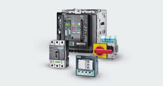
11 Siemens offers modular ancillary equipment units for indication, control and monitoring of the flow of power through busbar trunking systems. These units are equipped with bus interfaces, command devices and power meters. In the petrochemical industry, it is the LR system that provides reliable and fault-free power supply. The LX busbar trunking system is the perfect equipment for multi-storey buildings where large quantities of power need to be transported, uninfluenced by the mounting position of the system. High availability in production The ventilated LD system (up to 000 A) conveys electricity to production facilities with a high demand for power, e.g. in the automobile industry. A separate PE bar enables the assured response of the protective device over long conducting paths. The high short-circuit resistance permits protection by medium-voltage circuit breakers for the conveyance of power between the transformer and the main infeed. Tap-off units up to 120 A can be plugged in without causing any problems. Flexible power distribution for multi-storey buildings The LX sandwich-style system (up to 6300 A) is used wherever large quantities of power have to be conveyed independently of the mounting position. Be it for radio broadcasting stations, computer centers or Internet providers conductor configurations with an insulated PE/ ground conductor and double neutral conductor cross-section guarantee an interference-free power supply. Tap-off units up to 120 A are available as standard. Safe power transmission for petrochemicals The encapsulated LR system (up to 6300 A) is extremely resistant to external interference thanks to its high degree of protection. It guarantees the safe conveyance of power in severe weather as well as under harsh industrial conditions with dust, dirt and aggressive media. Typical applications are the petrochemical industry, waste incineration plants and power stations. Siemens LV /7

12 Made-to-measure, economical solutions. SIVACON 8PS Engineering Tools. SIVACON Engineering Tools from Siemens help generate precisely dimensioned and efficient solutions in planning and design. You are in full control of even complex tasks at all times. In MobileSpice, you select the trunking units for your system from a menu, and then transfer them into an order list. Selection aid for busbar trunking systems (MobileSpice) The selection aid enables you to order busbar trunking systems up to 120 A and is available in the Mall. The same selection aid can also be found in Catalog CA 01 on DVD. The following configurators are available: SIVACON 8PS system CD-L, 2 A and 40 A SIVACON 8PS system BD01, 40 A to 160 A SIVACON 8PS system BD2, 160 A to 120 A Should you have any queries concerning installation, functionality or application options please mail us at sbts.tool_support.aud@siemens.com We will be pleased to assist you. 1/8 Siemens LV

13 Busbar Trunking Systems, Overview 2 Contents 2/2 Overview System overview 2/4 Overview 2/ Benefits 2/ More information Features overview 2/6 Overview Principles of busbar trunking planning 2/8 Overview Communication-capable busbar trunking systems for industry and buildings 2/9 Overview 2/10 Application Busbars instead of cables 2/11 Overview Siemens LV

14 Busbar Trunking Systems, Overview Contents Overview Busbar trunking systems This catalog contains: 7 CD-L system up to 40 A 7 BD01 system up to 160 A 7 BD2 system up to 120 A Systems up to 6300 A on request. 2 Trunking unit with tap-off unit Feeder unit (end feeder unit) 2/2 Siemens LV
15 Busbar Trunking Systems, Overview Contents CD-L system 2 A and 40 A BD2 system 160 A to 120 A G_NSV0_0162 NSV0_00421 Page System overview of busbar trunking systems 2/4 Technical overview of busbar trunking systems 2/6 Contents: CD-L system 3/1 Overview 3/2 Design 3/3 Technical specifications 3/10 Selection and ordering data 3/12 Configuration 3/32 Dimensional drawings 3/39 Page System overview of busbar trunking systems 2/4 Technical overview of busbar trunking systems 2/6 Contents: BD2 system /1 Overview /2 Design /4 Technical specifications /14 Selection and ordering data /22 Configuration /73 Fire protection /94 Dimensional drawings /102 2 BD01 system 40 A to 160 A NSV0_00241 Page System overview of busbar trunking systems 2/4 Technical overview of busbar trunking systems 2/6 Contents: BD01 system 4/1 Overview 4/2 Design 4/3 Technical specifications 4/9 Selection and ordering data 4/11 Configuration 4/29 Dimensional drawings 4/34 Siemens LV /3
16 D 0 1 -K D B D -K Busbar Trunking Systems, Overview System overview Overview 2 B B B B 2/4 Siemens LV
17 Busbar Trunking Systems, Overview System overview Benefits $ CD-L system up to 40 A The versatile busbar trunking system for area-wide power supply to lighting systems: Versatile thanks to high degree of protection IP Lower planning costs through simple configuration Quick-release plug-in connection for fast assembly Variable changes of direction Tap-off points on both sides for optimized utilization of the busbar line Uniform current loading of the conductors through splitting of the tap-off plugs among the individual phases Tap-off plugs allow fast and flexible load relocation % BD01 system up to 160 A The busbar trunking system for power conveyance in craft business and the skilled trades: High degree of protection up to IP Flexible power supply Easy and quick planning Time-saving mounting Reliable mechanical and electrical connection High stability, low weight Few basic modules required Storage-friendly system Variable changes of direction Versatile tap-off units Positive opening and closing of tap-off points & BD2 system up to 120 A The busbar trunking system for operation in the harsh industrial world: High degree of protection up to IP Easy and quick planning Time-saving and economical mounting Reliable and safe operation Flexible modular system with simple solutions for every application Early planning of the power distribution system without exact knowledge of load locations Early readiness for operation thanks to fast and simple mounting Innovative design: No more compensation boxes to compensate elongation. Codable tap-off units and tap-off points Sealable throughout ( LD system up to 000 A The busbar trunking system for optimized power distribution in industry: High degree of protection IP4 Quick and easy mounting Reliable and safe operation Space-saving, compact design up to 000 A in one enclosure Load outgoing feeders up to 120 A Type-tested connection to distribution boards and transformers ) LX system up to 6300 A The busbar trunking system for power transmission and distribution in buildings: High degree of protection up to IP Quick and easy mounting Reliable and safe operation Load outgoing feeders up to 120 A Type-tested connection to distribution boards and transformers LR system The busbar trunking system for power transmission under extreme ambient conditions (IP68). Detailed information about this system is available from the Siemens branch located close to you. * Communication-capable busbar trunking systems Communication-capable function expansions for combination with known tap-off units: Can be used with the systems BD01, BD2, LD and LX Applications: - Lighting control for large areas - Remote switching and signaling in the industrial sector - Consumption recording of decentral power outgoing feeders Connection to the bus systems EIB, AS-Interface and PROFIBUS Easy contacting of the bus cable by insulation displacement method Easy and quick planning Flexible expansions and modifications Module system Retrofitting of existing installations More information Selection aid for busbar trunking systems (MobileSpice) The selection aid enables you to order busbar trunking systems up to 120 A. The following configurators are available: SIVACON 8PS system CD-L, A SIVACON 8PS system BD01, A SIVACON 8PS system BD2, A This selection aid can be accessed through the A&D Mall and is also included in the catalog CA 01 on DVD. This DVD is available free of charge from your Siemens sales office. Manual Planning with SIVACON 8PS Busbar Trunking Systems up to 6300 A English: Order No. AE German: Order No. AE Leaflet Busway Systems for Safe and Flexible Power Distribution up to 6300 A English: Order No. E20001-A220-P309-V German: Order No. E20001-A220-P309-V2 2 Siemens LV /
18 Busbar Trunking Systems, Overview Features overview Overview 2 Busbar trunking systems Rated current Rated operational voltage CD-L G_NSV0_0162 Frequency Number of active conductors Degree of protection Ambient temperature, min./max. A V AC Hz C On one side: IP /+40 2, 4, 6 On both sides: 2 2, , 2 4, 2 6 (PE = enclosure) BD NSV0_ Up to IP (PE = enclosure) /+40 BD2A BD2C , Up to IP /+40 NSV0_00421 LDA1... LDA8 LDC2... LDC , or Up to IP4 /+40 NSV0_00681 LXA01... LXA10 LXC01... LXC , , 4,, 6 Up to IP (PE = enclosure) /+40 NSV0_00321 LRC01... LRC , IP68 /+40 NSV0_0141 2/6 Siemens LV
19 Busbar Trunking Systems, Overview Features overview Mounting position Edgewise Length Tap-off points Tap-off units Material Fire load Can be combined with communication-capable tap-off units for m kwh/m On one side: every 0.; 1 or 1. m On two sides: every 0.; 1 or 1. m Up to 16 A Insulated Cu conductors, painted sheetsteel enclosure On one side: 0.7 On both sides: Edgewise, flat (tap-off points downwards) 2 3 On one side every 0. or 1 m Up to 63 A Insulated aluminum or copper conductors, painted sheet-steel enclosure 0.76 Lighting control Edgewise, flat and vertical None On two sides offset every 0.2 or 0. m Up to 630 A Al or Cu busbars, painted sheetsteel enclosure (without tap-off points) Lighting control, remote switching, signaling and consumption measurement Horizontal, edgewise and vertical None On one side every 1 m On two sides every 1 m Up to 120 A Insulated aluminum or copper busbars, painted sheetsteel enclosure (without tap-off points) Remote switching, signaling and consumption measurement Horizontal, edgewise and vertical None On one side every 0. m On two sides every 0. m Up to 120 A Insulated Al or Cu busbars, painted aluminum enclosure (without tap-off points) Remote switching, signaling and consumption measurement Horizontal, edgewise and vertical None On one side selectable Up to 630 A Epoxy resin system, Cu busbars Siemens LV /7

20 Busbar Trunking Systems, Overview Principles of busbar trunking planning 2 Overview Trunking units for currents from 40 to 6300 A When it comes to developing a power distribution concept, including the configuring of systems and components, it is necessary to coordinate the requirements and possibilities of the end-user with those of the manufacturer. With this in mind, the individual systems are described along with their technical features and applications. Another element is the graphic representation of the various busbar trunking elements. All details of importance for the planning work are specially emphasized and explained. You will find ideas for a ready-to-use planning solution in chapters 3 to under "Configuration information". For example, dimensioning principles are presented and in-depth information given on subjects such as system design, short-circuit protection, fire protection through compartmentalization or functional endurance. Services and engineering tools are available from Siemens to simplify the drawing up of customer specifications. General information When developing the planning concept of a power supply system it is necessary not only to consider the standards and specifications in force but also to clarify the correlations between economy and technology. Electrical equipment such as distribution boards and transformers must be dimensioned and selected so that they represent an optimum in their entirety and not just individually. All components must be sufficiently dimensioned for the loads which arise in the event of a fault as well as during operation at rated values. Other decisive points to be considered when drawing up the power concept are: The type, utilization and shape of building (e.g. high-rise, flat-roof and number of storeys) Determination of load centers and fixing of possible supply routes and locations for transformers and main distribution boards Fixing of building-related rating values according to specific area loads depending on the building's use Specifications and requirements imposed by the building authorities Requirements imposed by the power supply companies The result will never be a single solution but several versions which must be assessed with regard to their technical and economic implications. The following requirements are paramount in this connection: Easy and clear-cut planning Long endurance High availability Low fire load Flexible adaptation to alterations inside the building In most applications these requirements are easily met by the use of suitable busbar trunking systems. For this reason, busbar trunking systems rather than the cable installation method is being used more and more often by engineering offices for the conveyance and distribution of power. Siemens offers busbar trunking systems from 2 to 6300 A: The CD-L busbar system from 2 to 40 A for supplying power to lights and miniature loads The BD01 busbar system from 40 to 160 A for supplying power to workshops with tap-off units up to 63 A The BD2 system from 160 to 120 A for supplying power to medium-size loads in buildings and in industry The LD system for supplying power to loads with medium power consumption and in industry The LX sandwich system for the distribution of large amounts of power in buildings The LR encapsulated system for the conveyance of power in extreme ambient conditions (IP68) 2/8 Siemens LV

21 Busbar Trunking Systems, Overview Communication-capable busbar trunking systems for industry and buildings Overview Busbar trunking systems The strengths of busbar trunking systems lie in the conveyance and distribution and the switching and protecting of electrical power. The integration of automation and building management systems in the Siemens busbar trunking systems results in additional benefits and at the same time increases the flexibility of the busbar trunking. The combination of standard tap-off units with standard ancillary equipment units ensures efficiency particularly in planning, installation and operation. Advantages of the system solution during planning: Modular system Tested standard components Free choice of bus system Use of common bus systems Advantages of the system solution during start-up: Easy and quick installation Start-up in steps possible Flexible in case of expansions and modifications Advantages of the system solution during operation: Transparency of switching states Central recording of power costs Increase in plant availability as a result of immediate detection of the type of fault and its location Preventive maintenance through recording of operating hours and operating cycles System concept of communication-capable busbar trunking systems Switching and reporting with the BD2 system The standardized tap-off units of the busbar trunking systems can be combined with standard types of ancillary equipment units to form a system solution of communication-capable busbar trunking. The standard applications are assembled at the factory from a combination of tap-off unit and ancillary equipment unit. The bus cable for transmitting the data signals is laid in a cable duct which must be mounted on the trunking unit. 2 Siemens LV /9
22 Busbar Trunking Systems, Overview Communication-capable busbar trunking systems for industry and buildings 2 Application Standard application: lighting control The lighting control application enables the efficient and lowcost implementation of lighting control systems for large areas such as are used, for example, in supermarkets, furniture stores or DIY centers. The power bus is formed by BD01 or BD2 busbar trunking systems from Siemens, depending on the current requirement. The standard tap-off units are equipped with miniature circuit breakers or fuses and feed CD-L busbar systems which act simultaneously as the support system for the lighting elements. The economical and efficient control of extensive lighting systems is thus possible. The EIB (European Installation Bus) or AS-Interface bus systems are suitable for standard applications. On live busbar systems the tap-off point for power and bus can be adapted to the operational requirements. Possible functions of the lighting control Three times single-pole switching (L1, L2, L3) or 1/3, 2/3, 3/3 control Feedback of switching states Lamp test Recording of operating hours and operating cycles Standard application for consumption recording The consumption recording function enables the central recording of distributed power meters. The time-consuming reading of local meters is no longer necessary. Integration of the consumption recording in a visualization or I&C system by means of the data bus creates maximum transparency in the power distribution board. If recorded continuously, the measured values collected can be assigned to cost centers at a central point. The evaluation of trends and histories enables the data acquired to be analyzed. The combinations of tap-off unit and ancillary equipment unit can be equipped with either calibrated or non-calibrated power meters and enable the quick and transparent presentation of power consumption levels at the power tap-off points. The power bus is formed by BD2, LD or LX busbar trunking systems from Siemens, depending on the current requirement. Transformer sets (non-calibrated and calibrated) are available for the various tap-off units and levels of current. Possible functions for consumption recording Recording of consumption data Resetting of meter total Indication of a group fault Indication in the event of meter overflow, calling up of historical data Standard application for switching and reporting The application for switching and reporting enables the remote switching and remote monitoring of power or motor outgoing feeders. The power supply becomes highly transparent through the central recording of switching and operating states. In the event of a fault, the type of fault, e.g. short-circuit or overload tripping, and its location are detected quickly and efficiently so that the availability of the power supply system is effectively increased. The power bus is formed by BD2, LD or LX busbar trunking systems from Siemens, depending on the current requirement. The combinations of standard tap-off unit and standard ancillary equipment unit are equipped with corresponding switching devices and enable the centrally controlled switching and monitoring of the circuit breakers. The AS-Interface or PROFIBUS bus systems are suitable for standard applications. Possible functions for switching and reporting Central recording of switching and operating states Local and central switching Switching on is monitored by means of an integrated run-time monitor Fault signal inputs Group fault signal Short-circuit signal Overload signal Recording of operating hours and operating cycles Limit value signals 2/10 Siemens LV


.")

23 Busbar Trunking Systems, Overview Busbars instead of cables Overview Easier when it comes to planning Easy to plan, quick to install and flexible to use: Siemens busbar trunking systems are the economical answer for conveying power into any building. The power distribution system can be precisely planned from the total load rating and the type and number of loads. Clarity is assured by the line-shaped network topology with regularly arranged load feeders. All applications can be implemented in less time and space with standardized sizes. Quicker when it comes to installing Benefits during installation: Busbar trunking systems can be installed by two persons, saving time and money compared to the costly cable installation method. Installation errors are practically ruled out by the safe and user-guided connection technology. No special tools are required. Another benefit for quick installation: Siemens busbar trunking systems are easy to fasten and have large intervals between supports (busbars up to 4 m, cables every 1. m). Siemens busbar trunking systems are an economical alternative to the cable installation method. High short-circuit strength and minimum fire load result in greater safety A step-ahead in terms of safety be it short-circuit strength or fire load. For example, the BD2A-20 busbar trunking systems have a fire load of only 1.32 kwh/m; comparable cables (NYY 4 9/0 mm 2 ) have.19 kwh/m by contrast. And the busbars are halogen-free. Siemens busbar trunking systems have a high short-circuit strength. Also, the near-load protection against short-circuiting simplifies troubleshooting. 2 High fire load with cables With cable installation, new loads are connected by way of an additional sub-distribution board, which is costly and time-consuming Tap-off units near the loads make local arrangements more transparent Low fire load with busbar trunking system More flexible in case of expansions and modifications If the power distribution system has to be adapted to new requirements, the busbar will take you quicker to your goal. For example, new tap-off units can simply be mounted on the tap-off points. The system can be expanded and modified without difficulty. Tap-off units and system parts increase the flexibility. Cost-intensive downtimes are eliminated or minimized. The power distribution system enables faultless operation with high user-friendliness and safety. Siemens LV /11
24 Busbar Trunking Systems, Overview Notes 2 2/12 Siemens LV
25 CD-L System A 3 Introduction 3/2 Overview 3/3 Benefits 3/4 Design 3/8 Accessories General data 3/10 Technical specifications Trunking units 3/12 Selection and ordering data Feeder units 3/18 Overview 3/18 Selection and ordering data End flanges 3/22 Overview 3/22 Selection and ordering data Junction units 3/24 Overview 3/24 Selection and ordering data Tap-off plugs 3/26 Selection and ordering data Accessories 3/30 Selection and ordering data Configuration information 3/32 Overview 3/33 Design 3/37 Function Project planning aids 3/39 Dimensional drawings Siemens LV
26 CD-L System A Introduction Overview 3 Entry feeder unit Universal suspension bracket CD-L busbar trunking unit Cable duct Standard fixing bracket Fixing bracket for cable duct Flexible junction unit Tap-off plug Fixing bracket with hook End flange 3/2 Siemens LV
27 CD-L System A Introduction Version Type-tested low-voltage switchgear and controlgear assembly (TTA) according to IEC/EN IEC/EN Degree of protection High degree of protection to IP of the standard version Components Trunking units Insulated round conductors, one-side arrangement: 3-, -, 7-conductor system Insulated round conductors, two-side arrangement: 2 x 3-, 1x - / 1 x 3-, 2 x - and 2 x 7-conductor system Number and arrangement of the tap-off points: Benefits 7 Lower planning costs through simple configuration 7 Quick-release plug-in connection for fast assembly 7 Tap-off points on two sides for optimized utilization of the busbar line 7 Variable change of the direction of the busbar line 7 Uniform current loading of the conductors through splitting of the tap-off plugs among the individual phases 7 Tap-off plugs allow fast and flexible load relocation 7 Degree of protection to IP for extreme ambient conditions Length of trunking unit Plug-in connection Standard tap-off points Coded tap-off points Feeder units Entry feeder units End feeder units End flanges Number of tap-off points Equipment on one side Equipment on two sides Spacing of tap-off points m m 3 6, 3 or 2 2 (6, 3 or 2) 0., 1 or Junction units Flexible junction units Tap-off plugs 3-pole, 10 A and 16 A, Lx (phase can be plugged over optionally to L1, L2, L3), N and PE -pole, 10 A, L1, L2, L3, N, PE 3-pole + L4/L, 10 A (N/L1, N/L2 or N/L3) + L4/L + PE Standard and coded versions Mobile N and L contacts Accessories Fixing bracket Suspension hook Suspension bracket Cable duct Cable duct mounting Cover for tap-off point Siemens LV /3
28 CD-L System A Introduction Design Trunking units Connections A B 3 G_NSV0_0101 Trunking units The trunking units are available in 1., 2 and 3 meter lengths. They consist of a square, galvanized metal enclosure with white (RAL 9016) painted or unpainted finish. They are equipped on one side or two sides with insulated round conductors: 2 conductors for L3 + N (PE = enclosure), one-side or two-side 4 conductors for L1 + L2 + L3 + N (PE = enclosure), one-side or two-side 6 conductors for L4 + L1 + L2 + L3 + N + L (PE = enclosure). PE L4 L3 L2 L1 N L G_NSV0_0102 L3 N2 PE L4 L3 L3 N2 L2 L1 N L G_NSV0_0103 Conductor arrangement, one-side and two-side The tap-off points are spaced at regular intervals of 0. m, 1 m or 1. m on the trunking unit. The trunking unit enclosure acts as the PE conductor. 2 current strengths are available: 2 A, 2 2 A, 40 A and 2 40 A. All trunking units are equipped with finger-safe tap-off points. L N L1 L2 L3 L4 PE N2 L3 G_NSV0_0104 Plug-in connection The trunking units, including those with feeder units and end flanges, are assembled by a straightforward plug-in connection and fixing by a screw. The PE path is established automatically when the enclosures are connected. An interlock mechanism with two fixings prevents a loosening of the connections between the trunking units, feeder unit and flange. The fixing prevents the connection from becoming undone. No expansion compensation is required. Feeder units G_NSV0_0110 G_NSV0_0111 Feeder units, one-side and two-side The feeder units are used to feed the cable and are available as entry and end feeder units and are connected with the corresponding end of the straight element (the entry feeder unit with fixing screw and without connecting flange, the end feeder unit with connecting flange). Two versions are available in various conductor arrangements: As an entry feeder unit (EA) for 2 A, 2 2 A, 40 A and 2 40 A, As an end feeder unit (EE) for 2 A, 2 2 A, 40 A and 2 40 A. Cable entry from 1 side; use cable gland made of plastic, metric M2 or M32 with strain relief (not included in scope of supply). 3/4 Siemens LV
29 CD-L System A Introduction End flanges Tap-off plugs Insulated tap-off plugs are used for taking current from the tapoff points on the trunking units. They can be mounted and removed by hand. This is even possible with live busbars. Standard tap-off plugs G_NSV0_0108 End flanges, one-side and two-side The end flanges serve as touch protection at the end of the busbar trunking line opposite to the feeder unit. They are available in two versions for connecting with the corresponding straight element. End flange (EA-EF); can be used if the cable line begins with an entry feeder unit, End flange (EE-EF); can be used if the cable line begins with an end feeder unit. Junction units G_NSV0_0106 G_NSV0_0109 G_NSV0_0107 Junction units, one-side and two-side The flexible junction units enable a change of the busbar line progression in each direction and also used for bridging obstacles along the busbar. G_NSV0_0112 Standard tap-off plug Single-phase tap-off plugs with transparent top part to allow pole selection are available. They can be used on standard tap-off points or coded tap-off points. Standard tap-off plugs are identified by a gray base. The tap-off plugs are available in the following versions: 3-pole, without fuse, 16 A, Lx (phase can be changed optionally to L1, L2, L3 ), N and PE 3-pole, with fuse, 16 A and 6.3 A, Lx (phase can be changed optionally to L1, L2, L3 ), N and PE The tap-off plugs can be equipped with L4/L contacts to be used on the 7-conductor and 7+7-conductor trunking units. Phase selection allows wiring of either single-phase circuits with separate neutral conductor (N/L1, N/L2, N/L3) or three-phase circuits with common neutral conductor (N/L1/L2/L3). Standard tap-off plugs are fitted with a neutral conductor and a phase contact; with the withdrawable version of an additional mobile contact they can be used as tap-off plugs for three-phase circuits. 7 Mobile contacts 3 G_NSV0_0113 G_NSV0_0114 G_NSV0_011 G_NSV0_0116 Mobile contacts, with and without fuse They are intended for use in the tap-off plugs with phase selection to feed three-phase circuits. 1-pole, 16 A, without fuse (blue color for the neutral conductor) 1-pole, 16 A, without fuse (black color for the phase) 1-pole, 10 A, with phase melting fuse 6.3 A ( mm x 20 mm) 1-pole, 16 A with phase melting fuse 10 A (8. mm x 31. mm) Siemens LV /
30 CD-L System A Introduction Factory-wired standard tap-off plugs 7 Factory-wired tap-off plugs (2 conductors + PE) The standard version is designed for 10 A and fitted with 1 m long 3 x 1 mm² FROR cable, with four circuit configurations: N/L1, N/L2, N/L3, N2/L3. The top part of the tap-off plug is orange and the base can have different colors, depending on the wired circuit. Circuit configuration Top part Base N/L1 Orange Gray N/L2 Orange Green N/L3 Orange Black N2/L3 Orange Brown 7 Factory-wired tap-off plugs (2 conductors + L4/L + PE) The standard version is designed for 10 A and fitted with 2 m long x 1 mm² FROR cable, with three circuit configurations: N/L1 + L4/L, N/L2 + L4/L, N/L3 + L4/L. The top part of the tap-off plug is black and the base can have different colors, depending on the wired circuit. Circuit configuration Top part Base N/L1 + L4/L Black Gray N/L2 + L4/L Black Green N/L3 + L4/L Black Black G_NSV0_0122 G_NSV0_0123 G_NSV0_0117 G_NSV0_ G_NSV0_0124 G_NSV0_0119 G_NSV0_0120 Standard tap-off plugs They can be used on standard tap-off points or coded tap-off points. 7 Factory-wired tap-off plugs (4 conductors + PE) The standard version is designed for 10 A and fitted with 2 m long x 1 mm² FROR cable, with the circuit configuration: N/L1/L2/L3, the top part and the base of the tap-off plug is orange. Standard tap-off plugs These tap-off plugs are used in 7-conductor and 7+7-conductor trunking units. They can be used on standard tap-off points or coded tap-off points. 7 Factory-wired tap-off plugs (L4/L + PE) The standard version is designed for 10 A and fitted with 1 m long 3 x 1 mm² FROR cable, with the circuit configuration: L4/L. The top part and the base of the tap-off plug are orange. Circuit configuration Top part Base L4 / L Orange Orange Circuit configuration Top part Base N/L1, L2, L3 Orange Orange G_NSV0_012 G_NSV0_0121 Standard tap-off plug They can be used on standard tap-off points or coded tap-off points. Standard tap-off plug These tap-off plugs are used in 7-conductor and 7+7-conductor trunking units. They can be used on standard tap-off points or coded tap-off points. 3/6 Siemens LV
31 CD-L System A Introduction Coded tap-off plugs Single-phase tap-off plugs with transparent top part to allow pole selection are available. The base can be red (KR) or white (KW). These tap-off plugs are mechanically coded and can only be used on coded tap-off points. The (KR) tap-off plugs (red base) can only be used on busbar systems with red tap-off point (KR version). The (KW) tap-off plugs (white base) can only be used on busbar systems with white tap-off point (KW or KRW version). Circuit configuration Top part Base N/L1 Red Gray N/L2 Red Green N/L3 Red Black N2/L3 Red Brown G_NSV0_0128 G_NSV0_0129 G_NSV0_0126 G_NSV0_0127 Coded tap-off plugs The tap-off plugs are available in the following versions: 3-pole, without fuse, 16 A, Lx (phase can be changed optionally to L1, L2, L3), N and PE 3-pole, with fuse, 16 A and 6.3 A, Lx (phase can be changed optionally to L1, L2, L3), N and PE Tap-off plugs can be equipped with L4/L contacts to be used with the 7-conductor and 7+7-conductor trunking units. Phase selection allows wiring of either single-phase circuits with separate neutral conductor (N/L1, N/L2, N/L3) or three-phase circuits with common neutral conductor (N/L1/N2/L3). Standard tap-off plugs are fitted with a neutral conductor and a phase contact, but with the withdrawable version of an additional mobile contact (see page 3/), can be used as tap-off plugs for three-phase circuits. Coded, wired tap-off plugs 7 Factory-wired coded tap-off plugs (2 conductors + PE) KR The standard version is designed for 10 A and fitted with 1 m long 3 x 1 mm² FROR cable, with four circuit configurations: N/L1, N/L2, N/L3, N2/L3. The top part of the tap-off plug is orange and the base can have different colors, depending on the wired circuit. G_NSV0_0130 G_NSV0_0131 Coded tap-off plugs These mechanically coded tap-off plugs can only be used on coded tap-off points (colored red, KR version). 7 Factory-wired coded tap-off plugs (2 conductors + PE) KW The standard version is designed for 10 A and fitted with 1 m long 3 x 1 mm² FROR cable, with four circuit configurations: N/L1, N/L2, N/L3, N2/L3. The top part of the tap-off plug is white and the base can have different colors, depending on the wired circuit. Circuit configuration Top part Base N/L1 White Gray N/L2 White Green N/L3 White Black N2/L3 White Brown 3 G_NSV0_0132 G_NSV0_0133 G_NSV0_0134 G_NSV0_013 Coded tap-off plugs These mechanically coded tap-off plugs can only be used on coded tap-off points (colored white, KW version). Siemens LV /7
32 CD-L System A Introduction Accessories Suspension The trunking unit profile allows attachment of the suspension and fixing brackets at any point of the trunking unit. Standard fixing brackets Fixing brackets with hook G_NSV0_0141 G_NSV0_ G_NSV0_0137 G_NSV0_0138 Fixing brackets, one-side and two-side These brackets can be used: for mounting the trunking units on the floor or on the ceiling for suspending luminaires on the trunking unit. The fixing brackets are secured to the ceiling by chains or steel wire using suitable suspension brackets. Recommended spacing between fixing brackets 3 m. Available for loads up to 12 kg. Universal suspension brackets Fixing brackets with hook, one-side and two-side These brackets can be used: for mounting the trunking units on chains or steel wires, for suspending luminaires on the trunking unit. Open/closed hooks G_NSV0_0143 G_NSV0_0144 G_NSV0_0139 G_NSV0_0140 Hooks, open and closed These hooks can be used with the fixing/suspension brackets and fixing brackets for cable ducts: for mounting the trunking unit on the ceiling with chains or steel wires for suspending luminaires on the trunking unit. Suspension brackets, one-side and two-side These brackets can be used: for suspending the trunking units on the wall, on the floor or on the ceiling for suspending the luminaires. The suspension brackets are secured to the ceiling by chains or steel wire using suitable suspension brackets (open/closed). Recommended spacing between fixing brackets 3 m. Available for loads up to 2 kg. 3/8 Siemens LV
33 CD-L System A Introduction Cable duct Cover G_NSV0_0136 G_NSV0_014 Cable duct (2 elements plugged together) The cable duct is made of plastic (white), standard length 3 m. It is used for cables in auxiliary circuits. It is mounted on the trunking unit with the fixing brackets for cable ducts. Fixing brackets for cable duct Cover The cover is used to restore degree of protection IP to the previously used tap-off point after an tap-off plug has been removed from an tap-off point. 3 G_NSV0_0146 Fixing bracket They are used with the standard fixing brackets or universal suspension brackets for mounting the trunking units of the cable ducts on the ceiling, on the floor or on the wall. Combined with the open/closed hooks, they can be secured on the ceiling with chains or steel wires. Siemens LV /9
34 CD-L System A General data Technical specifications General technical specifications Type Trunking units CD-L-... Standards and specifications IEC/EN and -2 Rated insulation voltage U i V AC/DC 690 Overvoltage category/degree of pollution III/3 Rated operational voltage U e V AC 400 Frequency Hz Climatic proofing Damp heat, constant, to IEC ; Damp heat, cyclical, according to IEC Ambient temperature C Degree of protection acc. to IEC/EN 6029 IP Material Trunking unit enclosures Galvanized, painted/unpainted sheet steel Busbars Insulated round-section copper wires Mounting position Edgewise; tap-off points at the side Weights See "Selection and Ordering Data" 3 Type CD-L-122 CD-L-124 CD-L-126 CD-L-222 CD-L-224 CD-L-224 CD-L-226 (/2) Conducting paths Rated insulation voltage U i V AC/DC Overvoltage category/degree of pollution III/3 III/3 III/3 III/3 III/3 III/3 III/3 Rated operational voltage U e V AC Frequency Hz Rated current I e conventional thermal current A ) ) at max. 40 C and 3 C on a 24 h average Impedance of conducting paths at 0 Hz and 20 C busbar temperature Resistance R 20 mω/m Reactance X 20 mω/m Impedance Z 20 mω/m Impedance of conducting paths under event of a fault AC resistance R F mω/m Reactance per unit length X F mω/m Impedance per unit length Z F mω/m Zero sequence impedance acc. to IEC/EN Resistance R 0 Phase to N mω/m Reactance X 0 Phase to N mω/m Impedance Z 0 Phase to N mω/m Resistance R 0 Phase to PE mω/m Reactance X 0 Phase to PE mω/m Impedance Z 0 Phase to PE mω/m Short-circuit strength Rated impulse withstand current I pk ka Rated short-time withstand current I cw (t = 1 s) ka Conductors Number of active conductors Conductor cross-section N, L1, L2, L3 mm L4, L mm PE (enclosure) Cu mm Conductor material Cu Cu Cu Cu Cu Cu Cu Fire load kwh/m Max. thermal load, I 2 t value A 2 s Fixing intervals at normal mechanical load m Position of tap-off points Depending on the type, on one side/two sides every 0. m, 1 m or 1. m 1) L4/L circuit: max. rated current 2 A. 3/10 Siemens LV
35 CD-L System A General data Type CD-L-1402 CD-L-1404 CD-L-1406 CD-L-2402 CD-L-2404 CD-L-2404 CD-L-2406 (/2) Conducting paths Rated insulation voltage U i V AC/DC Overvoltage category/degree of pollution III/3 III/3 III/3 III/3 III/3 III/3 III/3 Rated operational voltage U e V AC Frequency Hz Rated current I e conventional thermal current A ) ) at max. 40 C and 3 C on a 24 h average Impedance of conducting paths at 0 Hz and 20 C busbar temperature Resistance R 20 mω/m Reactance X 20 mω/m Impedance Z 20 mω/m Impedance of conducting paths under event of a fault AC resistance R F mω/m Reactance per unit length X F mω/m Impedance per unit length Z F mω/m Zero sequence impedance acc. to IEC/EN Resistance R 0 Phase to N mω/m Reactance X 0 Phase to N mω/m Impedance Z 0 Phase to N mω/m Resistance R 0 Phase to PE mω/m Reactance X 0 Phase to PE mω/m Impedance Z 0 Phase to PE mω/m Short-circuit strength Rated impulse withstand current I pk ka Rated short-time withstand current I cw (t = 1 s) ka Conductors Number of active conductors Conductor cross-section N, L1, L2, L3 mm L4, L mm PE (enclosure) Cu mm Conductor material Cu Cu Cu Cu Cu Cu Cu Fire load kwh/m Max. thermal load, I 2 t value A 2 s Fixing intervals at normal mechanical load m Position of tap-off points Depending on the type, on one side/two sides every 0. m, 1 m or 1. m 1) L4/L circuit: max. rated current 2 A. Feeder units, conductor cross-sections 3 Version Type N, L1, L2, L3 L4, L PE Tap-off plugs min. mm 2 max. mm 2 Entry feeder unit CD-L-...-EA 2. 6 (f) 10 (so, st) End feeder unit CD-L-...-EE 2. 6 (f) 10 (so, st) min. mm 2 max. mm 2 1. (f) 2. (so, st) 1. (f) 2. (so, st) f = finely stranded with end sleeve, so = solid, st = stranded Type CD-L-A... Version 3-, -pole or +2-pole Rated current I e A 6.3; 10 or 16 Switching capacity acc. to IEC/EN Utilization category AC-20B Connection With or without permanently attached cable; the PE is connected first when mounting the tap-off plug and is deconnected last when removing the tap-off plug Fuses With or without fuse holder for cylindrical fuses Size 8. mm 31. mm or mm 20 mm, type gg (IEC) or type gl (VDE) (quick) min. mm 2 max. mm (f) 6 (so, st) 2. 4 (f) 6 (so, st) Siemens LV /11
36 CD-L System A Trunking units Selection and ordering data Unpainted trunking units with uncoded tap-off points (supplied from stock) 3 Version Length Conductor configuration Tap-off points DT Type Order No. PS* Weight Number Spacing per unit approx. m m kg Rated current I e = 2 A, tap-off points on one side Trunking units 3 3 conductors 2 1. X CD-L , 8PS0300-3BF2 6 units Sheet-steel enclosure, 3 PE 3 1 X CD-L PS0301-3BF2 6 units unpainted, L3 uncoded tap-off points X CD-L , 8PS0302-3BF2 6 units N 2 1 X CD-L PS0300-2BF2 6 units X CD-L-122-1,-1 8PS0300-1BF2 6 units conductors 2 1. X CD-L , 8PS0300-3CF2 6 units PE 3 1 X CD-L PS0301-3CF2 6 units L3 L3 3 L2 N X CD-L , 8PS0302-3CF2 6 units L1 2 N 2 1 X CD-L PS0300-2CF2 6 units X CD-L-124-1,-1 8PS0300-1CF2 6 units G_NSV0_ conductors 1) 2 1. X CD-L , 8PS0300-3DF2 6 units PE 3 1 X CD-L PS0301-3DF2 6 units L4 L3 L3 3 L2 N X CD-L , 8PS0302-3DF2 6 units L1 2 N 2 1 X CD-L PS0300-2DF2 6 units L X CD-L-126-1,-1 8PS0300-1DF2 6 units 1.60 Rated current I e = 2 2 A, tap-off points on two sides Trunking units conductors 2 x 2 1. X CD-L , 8PS0300-3FF2 6 units.30 Sheet-steel enclosure, 3 PE 2 x 3 1 X CD-L PS0301-3FF2 6 units.30 unpainted, L3 N uncoded tap-off points 3 2 x 6 0. X CD-L , 8PS0302-3FF2 6 units.30 2 N L3 2 x 2 1 X CD-L PS0300-2FF2 6 units PE 1. 2 x 2 1 X CD-L-222-1,-1 8PS0300-1FF2 6 units conductors 2 x 2 1. X CD-L-224/2-KR-3-1, 8PS0303-3GF2 6 units conductors 2 x 3 1 X CD-L-224/2-KR-3-1 8PS0304-3GF2 6 units x 6 0. X CD-L-224/2-KR-3-0, 8PS030-3GF2 6 units x 2 1 X CD-L-224/2-KR-2-1 8PS0303-2GF2 6 units x 2 1 X CD-L-224/2-KR-1,-1 8PS0303-1GF2 6 units PE L3 L3 N N2 L2 L1 N L3 G_NSV0_0148 G_NSV0_0149 G_NSV0_010 G_NSV0_011 G_NSV0_012 G_NSV0_013 PE 3 2 conductors 2 x 2 1. X CD-L , 8PS0300-3HF2 6 units PE 2 x 3 1 X CD-L PS0301-3HF2 6 units L3 N2 L3 L2 N L1 2 x 6 0. X CD-L , 8PS0302-3HF2 6 units L1 L2 N2 N L3 L3 2 x 2 1 X CD-L PS0300-2HF2 6 units PE 2 x 2 1 X CD-L-224-1,-1 8PS0300-1HF2 6 units x 2 1. X CD-L , 8PS0300-3JF2 6 units conductors 1) 2 x 3 1 X CD-L PS0301-3JF2 6 units PE L3 L4 L3 L N 2 x 6 0. X CD-L , 8PS0302-3JF2 6 units N2 L2 L1 L1 L2 N2 2 x 2 1 X CD-L PS0300-2JF2 6 units N L3 L3 2 x 2 1 X CD-L-226-1,-1 8PS0300-1JF2 6 units G_NSV0_014 G_NSV0_01 L L4 PE 1) L4/L circuit: max. rated current 2 A. 3/12 Siemens LV * You can order this quantity or a multiple thereof.
37 CD-L System A Trunking units Version Length Conductor configuration Tap-off points DT Type Order No. PS* Weight Number Spacing per unit approx. m m kg Rated current I e = 40 A, tap-off points on one side Trunking units 3 3 conductors 2 1. X CD-L , 8PS0300-3BF40 6 units Sheet-steel enclosure, 3 PE 3 1 X CD-L PS0301-3BF40 6 units unpainted, L3 uncoded tap-off points X CD-L , 8PS0302-3BF40 6 units N 2 1 X CD-L PS0300-2BF40 6 units X CD-L ,-1 8PS0300-1BF40 6 units conductors 2 1. X CD-L , 8PS0300-3CF40 6 units PE 3 1 X CD-L PS0301-3CF40 6 units L3 L3 3 L2 N X CD-L , 8PS0302-3CF40 6 units L1 2 N 2 1 X CD-L PS0300-2CF40 6 units X CD-L ,-1 8PS0300-1CF40 6 units G_NSV0_ conductors 1) 2 1. X CD-L , 8PS0300-3DF40 6 units PE 3 1 X CD-L PS0301-3DF40 6 units L4 L3 L3 3 L2 N X CD-L , 8PS0302-3DF40 6 units L1 2 N 2 1 X CD-L PS0300-2DF40 6 units L X CD-L ,-1 8PS0300-1DF40 6 units Rated current I e = 2 40 A, tap-off points on two sides Trunking units conductors 2 x 2 1. X CD-L , 8PS0300-3FF40 6 units.920 Sheet-steel enclosure, 3 PE 2 x 3 1 X CD-L PS0301-3FF40 6 units.920 unpainted, L3 N uncoded tap-off points 3 2 x 6 0. X CD-L , 8PS0302-3FF40 6 units N L3 2 x 2 1 X CD-L PS0300-2FF40 6 units PE 1. 2 x 2 1 X CD-L ,-1 8PS0300-1FF40 6 units conductors 2 x 2 1. X CD-L-2404/2-KR-3-1, 8PS0303-3GF40 6 units conductors 2 x 3 1 X CD-L-2404/2-KR-3-1 8PS0304-3GF40 6 units x 6 0. X CD-L-2404/2-KR-3-0, 8PS030-3GF40 6 units x 2 1 X CD-L-2404/2-KR-2-1 8PS0303-2GF40 6 units x 2 1 X CD-L-2404/2-KR-1,-1 8PS0303-1GF40 6 units PE L3 L3 N N2 L2 L1 N L3 G_NSV0_0148 G_NSV0_0149 G_NSV0_010 G_NSV0_011 G_NSV0_012 G_NSV0_013 PE 3 2 conductors 2 x 2 1. X CD-L , 8PS0300-3HF40 6 units PE 2 x 3 1 X CD-L PS0301-3HF40 6 units L3 N2 L3 L2 N L1 2 x 6 0. X CD-L , 8PS0302-3HF40 6 units L1 L2 N2 N L3 L3 2 x 2 1 X CD-L PS0300-2HF40 6 units PE 2 x 2 1 X CD-L ,-1 8PS0300-1HF40 6 units x 2 1. X CD-L , 8PS0300-3JF40 6 units conductors 1) 2 x 3 1 X CD-L PS0301-3JF40 6 units PE L3 L4 L3 L N 2 x 6 0. X CD-L , 8PS0302-3JF40 6 units N2 L2 L1 L1 L2 N2 2 x 2 1 X CD-L PS0300-2JF40 6 units N L3 L3 2 x 2 1 X CD-L ,-1 8PS0300-1JF40 6 units G_NSV0_014 G_NSV0_01 L L4 PE 3 1) L4/L circuit: max. rated current 2 A. * You can order this quantity or a multiple thereof. Siemens LV /13
38 CD-L System A Trunking units Unpainted trunking units with codable tap-off points (supplied from stock) 3 Version Length Conductor configuration Tap-off points DT Type Order No. PS* Weight Number Spacing per unit approx. m m kg Rated current I e = 2 A, tap-off points on one side Trunking units 3 KR, 2 1. X CD-L-124-KR-3-1, 8PS0310-3CF2 6 units Sheet-steel enclosure, 3 conductors 3 1 X CD-L-124-KR-3-1 8PS0311-3CF2 6 units unpainted, coded tap-off points 3 PE 6 0. X CD-L-124-KR-3-0, 8PS0312-3CF2 6 units L3 L3 2 L2 L1 N2 2 1 X CD-L-124-KR-2-1 8PS0310-2CF2 6 units N 2 1 X CD-L-124-KR-1,-1 8PS0310-1CF2 6 units G_NSV0_018 G_NSV0_0164 G_NSV0_ KW, 2 1. X CD-L-124-KW-3-1, 8PS0313-3CF2 6 units conductors 3 1 X CD-L-124-KW-3-1 8PS0314-3CF2 6 units PE 6 0. X CD-L-124-KW-3-0, 8PS031-3CF2 6 units L3 L3 2 L2 L1 N2 2 1 X CD-L-124-KW-2-1 8PS0313-2CF2 6 units N 2 1 X CD-L-124-KW-1,-1 8PS0313-1CF2 6 units G_NSV0_ KR, 2 1. X CD-L-126-KR-3-1, 8PS0310-3DF2 6 units conductors 1) 3 1 X CD-L-126-KR-3-1 8PS0311-3DF2 6 units PE L X CD-L-126-KR-3-0, 8PS0312-3DF2 6 units L3 L3 2 L2 L1 N2 2 1 X CD-L-126-KR-2-1 8PS0310-2DF2 6 units N L 2 1 X CD-L-126-KR-1,-1 8PS0310-1DF2 6 units 1.60 G_NSV0_ KW, 2 1. X CD-L-126-KW-3-1, 8PS0313-3DF2 6 units conductors 1) 3 1 X CD-L-126-KW-3-1 8PS0314-3DF2 6 units PE L 6 0. X CD-L-126-KW-3-0, 8PS031-3DF2 6 units L3 L3 2 L2 L1 N2 2 1 X CD-L-126-KW-2-1 8PS0313-2DF2 6 units N L4 2 1 X CD-L-126-KW-1,-1 8PS0313-1DF2 6 units 1.60 G_NSV0_0163 Rated current I e = 2 2 A, tap-off points on two sides Trunking units 3 KR, 2 x 2 1. X CD-L-224/2-KR-3-1, 8PS0303-3GF2 6 units.740 Sheet-steel enclosure, 3 1 conductors 2 x 3 1 X CD-L-224/2-KR-3-1 8PS0304-3GF2 6 units.740 unpainted, 1 3 conductors coded tap-off points 3 2 x 6 0. X CD-L-224/2-KR-3-0, 8PS030-3GF2 6 units.740 PE 2 L3 L3 N 2 x 2 1 X CD-L-224/2-KR-2-1 8PS0303-2GF2 6 units N2 L2 1. L1 2 x 2 1 X CD-L-224/2-KR-1,-1 8PS0303-1GF2 6 units G_NSV0_019 G_NSV0_013 N L3 PE 3 KR/KW, 2 x 2 1. X CD-L-224-KRW-3-1, 8PS0316-3HF2 6 units conductors 2 x 3 1 X CD-L-224-KRW-3-1 8PS0317-3HF2 6 units PE L3 L3 N 2 x 6 0. X CD-L-224-KRW-3-0, 8PS0318-3HF2 6 units N2 L2 L1 L1 L2 N2 2 x 2 1 X CD-L-224-KRW-2-1 8PS0316-2HF2 6 units N L3 L3 2 x 2 1 X CD-L-224-KRW-1,-1 8PS0316-1HF2 6 units G_NSV0_016 PE 3 KR/KW, 2 x 2 1. X CD-L-226-KRW-3-1, 8PS0316-3JF2 6 units conductors 1) 2 x 3 1 X CD-L-226-KRW-3-1 8PS0317-3JF2 6 units x 6 0. X CD-L-226-KRW-3-0, 8PS0318-3JF2 6 units PE L3 L4 L3 L N 2 x 2 1 X CD-L-226-KRW-2-1 8PS0316-2JF2 6 units N2 L2 L1 L1 L2 N2 2 x 2 1 X CD-L-226-KRW-1,-1 8PS0316-1JF2 6 units G_NSV0_0166 N L L3 L3 L4 PE 1) L4/L circuit: max. rated current 2 A. 3/14 Siemens LV * You can order this quantity or a multiple thereof.
39 CD-L System A Trunking units Version Length Conductor configuration Tap-off points DT Type Order No. PS* Weight Number Spacing per unit approx. m m kg Rated current I e = 40 A, tap-off points on one side Trunking units 3 KR, 2 1. X CD-L-1404-KR-3-1, 8PS0310-3CF40 6 units Sheet-steel enclosure, 3 conductors 3 1 X CD-L-1404-KR-3-1 8PS0311-3CF40 6 units unpainted, coded tap-off points 3 PE 6 0. X CD-L-1404-KR-3-0, 8PS0312-3CF40 6 units L3 L3 2 L2 L1 N2 2 1 X CD-L-1404-KR-2-1 8PS0310-2CF40 6 units N 2 1 X CD-L-1404-KR-1,-1 8PS0310-1CF40 6 units G_NSV0_018 G_NSV0_0164 G_NSV0_ KW, 2 1. X CD-L-1404-KW-3-1, 8PS0313-3CF40 6 units conductors 3 1 X CD-L-1404-KW-3-1 8PS0314-3CF40 6 units PE 6 0. X CD-L-1404-KW-3-0, 8PS031-3CF40 6 units L3 L3 2 L2 L1 N2 2 1 X CD-L-1404-KW-2-1 8PS0313-2CF40 6 units N 2 1 X CD-L-1404-KW-1,-1 8PS0313-1CF40 6 units G_NSV0_ KR, 2 1. X CD-L-1406-KR-3-1, 8PS0310-3DF40 6 units conductors 1) 3 1 X CD-L-1406-KR-3-1 8PS0311-3DF40 6 units PE L X CD-L-1406-KR-3-0, 8PS0312-3DF40 6 units L3 L3 2 L2 L1 N2 2 1 X CD-L-1406-KR-2-1 8PS0310-2DF40 6 units N L 2 1 X CD-L-1406-KR-1,-1 8PS0310-1DF40 6 units G_NSV0_ KW, 2 1. X CD-L-1406-KW-3-1, 8PS0313-3DF40 6 units conductors 1) 3 1 X CD-L-1406-KW-3-1 8PS0314-3DF40 6 units PE L 6 0. X CD-L-1406-KW-3-0, 8PS031-3DF40 6 units L3 L3 2 L2 L1 N2 2 1 X CD-L-1406-KW-2-1 8PS0313-2DF40 6 units N L4 2 1 X CD-L-1406-KW-1,-1 8PS0313-1DF40 6 units G_NSV0_0163 Rated current I e = 2 40 A, tap-off points on two sides Trunking units 3 KR, 2 x 2 1. X CD-L-2404/2-KR-3-1, 8PS0303-3GF40 6 units Sheet-steel enclosure, 3 1 conductors 2 x 3 1 X CD-L-2404/2-KR-3-1 8PS0304-3GF40 6 units unpainted, 1 3 conductors coded tap-off points 3 2 x 6 0. X CD-L-2404/2-KR-3-0, 8PS030-3GF40 6 units PE 2 L3 L3 N 2 x 2 1 X CD-L-2404/2-KR-2-1 8PS0303-2GF40 6 units N2 L2 1. L1 2 x 2 1 X CD-L-2404/2-KR-1,-1 8PS0303-1GF40 6 units G_NSV0_019 G_NSV0_013 N L3 PE 3 KR/KW, 2 x 2 1. X CD-L-2404-KRW-3-1, 8PS0316-3HF40 6 units conductors 2 x 3 1 X CD-L-2404-KRW-3-1 8PS0317-3HF40 6 units PE L3 L3 N 2 x 6 0. X CD-L-2404-KRW-3-0, 8PS0318-3HF40 6 units N2 L2 L1 L1 L2 N2 2 x 2 1 X CD-L-2404-KRW-2-1 8PS0316-2HF40 6 units N L3 L3 2 x 2 1 X CD-L-2404-KRW-1,-1 8PS0316-1HF40 6 units G_NSV0_016 PE 3 3 KR/KW, 2 x 2 1. X CD-L-2406-KRW-3-1, 8PS0316-3JF40 6 units conductors 1) 2 x 3 1 X CD-L-2406-KRW-3-1 8PS0317-3JF40 6 units x 6 0. X CD-L-2406-KRW-3-0, 8PS0318-3JF40 6 units PE L3 L4 L3 L N 2 x 2 1 X CD-L-2406-KRW-2-1 8PS0316-2JF40 6 units N2 L2 L1 L1 L2 N2 2 x 2 1 X CD-L-2406-KRW-1,-1 8PS0316-1JF40 6 units G_NSV0_0166 N L L3 L3 L4 PE 1) L4/L circuit: max. rated current 2 A. * You can order this quantity or a multiple thereof. Siemens LV /1
40 CD-L System A Trunking units Painted trunking units with uncoded tap-off points (delivery on request) 3 Version Length Conductor configuration Tap-off points DT Type Order No. PS* Weight Number Spacing per unit approx. m m kg Rated current I e = 2 A, tap-off points on one side Trunking units 3 3 conductors 2 1. X CD-L ,-L 8PS1300-3BF2 6 units Sheet-steel enclosure, 3 PE 3 1 X CD-L L 8PS1301-3BF2 6 units painted, white (RAL 9016), L3 uncoded tap-off points X CD-L ,-L 8PS1302-3BF2 6 units N 2 1 X CD-L L 8PS1300-2BF2 6 units X CD-L-122-1,-1-L 8PS1300-1BF2 6 units conductors 2 1. X CD-L ,-L 8PS1300-3CF2 6 units PE 3 1 X CD-L L 8PS1301-3CF2 6 units L3 L3 3 L2 N X CD-L ,-L 8PS1302-3CF2 6 units L1 2 N 2 1 X CD-L L 8PS1300-2CF2 6 units X CD-L-124-1,-1-L 8PS1300-1CF2 6 units G_NSV0_ conductors 1) 2 1. X CD-L ,-L 8PS1300-3DF2 6 units PE 3 1 X CD-L L 8PS1301-3DF2 6 units L4 L3 L3 3 L2 N X CD-L ,-L 8PS1302-3DF2 6 units L1 2 N 2 1 X CD-L L 8PS1300-2DF2 6 units L X CD-L-126-1,-1-L 8PS1300-1DF2 6 units Rated current I e = 2 2 A, tap-off points on two sides Trunking units conductors 2 x 2 1. X CD-L ,-L 8PS1300-3FF2 6 units.30 Sheet-steel enclosure, 3 PE 2 x 3 1 X CD-L L 8PS1301-3FF2 6 units.30 painted, white (RAL 9016), L3 N uncoded tap-off points 3 2 x 6 0. X CD-L ,-L 8PS1302-3FF2 6 units.30 2 N L3 2 x 2 1 X CD-L L 8PS1300-2FF2 6 units PE 1. 2 x 2 1 X CD-L-222-1,-1-L 8PS1300-1FF2 6 units conductors 2 x 2 1. X CD-L-224/2-KR-3-1,-L 8PS1303-3GF2 6 units conductors 2 x 3 1 X CD-L-224/2-KR-3-1-L 8PS1304-3GF2 6 units.740 PE 3 2 x 6 0. X CD-L-224/2-KR-3-0,-L 8PS130-3GF2 6 units.740 L3 L3 N N2 2 L2 2 x 2 1 X CD-L-224/2-KR-2-1-L 8PS1303-2GF2 6 units L1 N L x 2 1 X CD-L-224/2-KR-1,-1-L 8PS1303-1GF2 6 units G_NSV0_017 G_NSV0_0149 G_NSV0_010 G_NSV0_011 G_NSV0_012 G_NSV0_013 PE 3 2 conductors 2 x 2 1. X CD-L ,-L 8PS1300-3HF2 6 units PE 2 x 3 1 X CD-L L 8PS1301-3HF2 6 units L3 N2 L3 L2 N L1 2 x 6 0. X CD-L ,-L 8PS1302-3HF2 6 units L1 L2 N2 N L3 L3 2 x 2 1 X CD-L L 8PS1300-2HF2 6 units PE 2 x 2 1 X CD-L-224-1,-1-L 8PS1300-1HF2 6 units x 2 1. X CD-L ,-L 8PS1300-3JF2 6 units conductors 1) 2 x 3 1 X CD-L L 8PS1301-3JF2 6 units PE L3 L4 L3 L N 2 x 6 0. X CD-L ,-L 8PS1302-3JF2 6 units N2 L2 L1 L1 L2 N2 2 x 2 1 X CD-L L 8PS1300-2JF2 6 units N L3 L3 2 x 2 1 X CD-L-226-1,-1-L 8PS1300-1JF2 6 units G_NSV0_014 G_NSV0_01 L L4 PE 1) L4/L circuit: max. rated current 2 A. 3/16 Siemens LV * You can order this quantity or a multiple thereof.
41 CD-L System A Trunking units Version Length Conductor configuration Tap-off points DT Type Order No. PS* Weight Number Spacing per unit approx. m m kg Rated current I e = 40 A, tap-off points on one side Trunking units 3 3 conductors 2 1. X CD-L ,-L 8PS1300-3BF40 6 units Sheet-steel enclosure, 3 PE 3 1 X CD-L L 8PS1301-3BF40 6 units painted, white (RAL 9016), L3 uncoded tap-off points X CD-L ,-L 8PS1302-3BF40 6 units N 2 1 X CD-L L 8PS1300-2BF40 6 units X CD-L ,-1-L 8PS1300-1BF40 6 units conductors 2 1. X CD-L ,-L 8PS1300-3CF40 6 units PE 3 1 X CD-L L 8PS1301-3CF40 6 units L3 L3 3 L2 N X CD-L ,-L 8PS1302-3CF40 6 units L1 2 N 2 1 X CD-L L 8PS1300-2CF40 6 units X CD-L ,-1-L 8PS1300-1CF40 6 units G_NSV0_ conductors 1) 2 1. X CD-L ,-L 8PS1300-3DF40 6 units PE 3 1 X CD-L L 8PS1301-3DF40 6 units L4 L3 L3 3 L2 N X CD-L ,-L 8PS1302-3DF40 6 units L1 2 N 2 1 X CD-L L 8PS1300-2DF40 6 units L X CD-L ,-1-L 8PS1300-1DF40 6 units Rated current I e = 2 40 A, tap-off points on two sides Trunking units conductors 2 x 2 1. X CD-L ,-L 8PS1300-3FF40 6 units.920 Sheet-steel enclosure, 3 PE 2 x 3 1 X CD-L L 8PS1301-3FF40 6 units.920 painted, white (RAL 9016), L3 N uncoded tap-off points 3 2 x 6 0. X CD-L ,-L 8PS1302-3FF40 6 units N L3 2 x 2 1 X CD-L L 8PS1300-2FF40 6 units PE 1. 2 x 2 1 X CD-L ,-1-L 8PS1300-1FF40 6 units conductors 2 x 2 1. X CD-L-2404/2-KR-3-1,-L 8PS1303-3GF40 6 units conductors 2 x 3 1 X CD-L-2404/2-KR-3-1-L 8PS1304-3GF40 6 units PE 3 2 x 6 0. X CD-L-2404/2-KR-3-0,-L 8PS130-3GF40 6 units L3 L3 N N2 2 L2 2 x 2 1 X CD-L-2404/2-KR-2-1-L 8PS1303-2GF40 6 units L1 N L x 2 1 X CD-L-2404/2-KR-1,-1-L 8PS1303-1GF40 6 units G_NSV0_017 G_NSV0_0149 G_NSV0_010 G_NSV0_011 G_NSV0_012 G_NSV0_013 PE 3 2 conductors 2 x 2 1. X CD-L ,-L 8PS1300-3HF40 6 units PE 2 x 3 1 X CD-L L 8PS1301-3HF40 6 units L3 N2 L3 L2 N L1 2 x 6 0. X CD-L ,-L 8PS1302-3HF40 6 units L1 L2 N2 N L3 L3 2 x 2 1 X CD-L L 8PS1300-2HF40 6 units PE 2 x 2 1 X CD-L ,-1-L 8PS1300-1HF40 6 units x 2 1. X CD-L ,-L 8PS1300-3JF40 6 units conductors 1) 2 x 3 1 X CD-L L 8PS1301-3JF40 6 units PE L3 L4 L3 L N 2 x 6 0. X CD-L ,-L 8PS1302-3JF40 6 units N2 L2 L1 L1 L2 N2 2 x 2 1 X CD-L L 8PS1300-2JF40 6 units N L3 L3 2 x 2 1 X CD-L ,-1-L 8PS1300-1JF40 6 units G_NSV0_014 G_NSV0_01 L L4 PE 3 1) L4/L circuit: max. rated current 2 A. * You can order this quantity or a multiple thereof. Siemens LV /17
42 CD-L System A Feeder units Overview The feeder units are installed at the beginning of a busbar line. They are available as entry and end feeder units and are connected with the corresponding end of the straight element (the entry feeder unit without connecting flange, the end feeder unit with connecting flange). The two circuits are mechanically separated on two-sided busbar elements. Enclosure material Connection boxes: thermoplast Connection point: galvanized metal enclosure Connection cross-sections of terminals N/L1/L2/L3: max. cable cross-section 10 mm 2 L4/L: max. cable cross-section 2. mm 2 PU: max. cable cross-section 6 mm 2 Selection and ordering data Unpainted feeder units (supplied from stock) 3 Version Length Conductor configuration DT Type Order No. PS* Weight per unit approx. m kg Rated current I e = 2 A, one-sided Entry feeder units, unpainted conductors X CD-L-124-EA 8PS0330-0CF2 1 unit 0.32 (coded KR, KW) L3, N conductors L3, L2, L1, N conductors 1) X CD-L-126-EA 8PS0330-0DF2 1 unit 0.37 G_NSV0_0167 L4, L3, L2, L1, N, L End feeder units, unpainted (coded KR, KW) G_NSV0_ conductors X CD-L-124-EE 8PS0332-0CF2 1 unit 0.20 L3, N conductors L3, L2, L1, N conductors 1) X CD-L-126-EE 8PS0332-0DF2 1 unit L4, L3, L2, L1, N, L Rated current I e = 2 2 A, two-sided Entry feeder units, unpainted (coded KR, KW) G_NSV0_0168 End feeder units, unpainted (coded KR, KW) G_NSV0_ conductors X CD-L-224-EA 8PS0331-0HF2 1 unit L3, N 1 conductors / 1 3 conductors 1 L3, L2, L1, N / 1 L3, N 2 conductors 2 L3, L2, L1, N conductors 1) X CD-L-226-EA 8PS0331-0JF2 1 unit L4, L3, L2, L1, N, L conductors X CD-L-224-EE 8PS0333-0HF2 1 unit L3, N 1 conductors / 1 3 conductors 1 L3, L2, L1, N / 1 L3, N 2 conductors 2 L3, L2, L1, N conductors 1) X CD-L-226-EE 8PS0333-0JF2 1 unit L4, L3, L2, L1, N, L 1) L4/L circuit: max. rated current 2 A. 3/18 Siemens LV * You can order this quantity or a multiple thereof.
43 CD-L System A Feeder units Version Length Conductor configuration DT Type Order No. PS* Weight per unit approx. m kg Rated current I e = 40 A, one-sided Entry feeder units, unpainted conductors X CD-L-1404-EA 8PS0330-0CF40 1 unit (coded KR, KW) L3, N conductors L3, L2, L1, N conductors 1) X CD-L-1406-EA 8PS0330-0DF40 1 unit G_NSV0_0167 L4, L3, L2, L1, N, L End feeder units, unpainted (coded KR, KW) G_NSV0_ conductors X CD-L-1404-EE 8PS0332-0CF40 1 unit 0.0 L3, N conductors L3, L2, L1, N conductors 1) X CD-L-1406-EE 8PS0332-0DF40 1 unit 0.60 L4, L3, L2, L1, N, L Rated current I e = 2 40 A, two-sided Entry feeder units, unpainted (coded KR, KW) G_NSV0_0168 End feeder units, unpainted (coded KR, KW) G_NSV0_ conductors X CD-L-2404-EA 8PS0331-0HF40 1 unit L3, N 1 conductors / 1 3 conductors 1 L3, L2, L1, N / 1 L3, N 2 conductors 2 L3, L2, L1, N conductors 1) X CD-L-2406-EA 8PS0331-0JF40 1 unit L4, L3, L2, L1, N, L conductors X CD-L-2404-EE 8PS0333-0HF40 1 unit L3, N 1 conductors / 1 3 conductors 1 L3, L2, L1, N / 1 L3, N 2 conductors 2 L3, L2, L1, N conductors 1) X CD-L-2406-EE 8PS0333-0JF40 1 unit L4, L3, L2, L1, N, L 3 1) L4/L circuit: max. rated current 2 A. * You can order this quantity or a multiple thereof. Siemens LV /19
44 CD-L System A Feeder units Painted feeder units (delivery on request) Version Length Conductor configuration DT Type Order No. PS* Weight per unit approx. m kg Rated current I e = 2 A, one-sided Entry feeder unit, painted, white (RAL 9016) conductors X CD-L-124-EA-L 8PS1330-0CF2 1 unit 0.32 L3, N conductors L3, L2, L1, N G_NSV0_ conductors 1) X CD-L-126-EA-L 8PS1330-0DF2 1 unit 0.37 L4, L3, L2, L1, N, L End feeder unit, painted, white (RAL 9016) conductors X CD-L-124-EE-L 8PS1332-0CF2 1 unit 0.20 L3, N conductors L3, L2, L1, N conductors 1) X CD-L-126-EE-L 8PS1332-0DF2 1 unit G_NSV0_0172 L4, L3, L2, L1, N, L 3 Rated current I e = 2 2 A, two-sided Entry feeder unit, painted, white (RAL 9016) conductors X CD-L-224-EA-L 8PS1331-0HF2 1 unit 0.60 G_NSV0_ L3, N 1 conductors / 1 3 conductors 1 L3, L2, L1, N / 1 L3, N 2 conductors 2 L3, L2, L1, N conductors 1) X CD-L-226-EA-L 8PS1331-0JF2 1 unit L4, L3, L2, L1, N, L End feeder unit, painted, white (RAL 9016) conductors X CD-L-224-EE-L 8PS1333-0HF2 1 unit G_NSV0_ L3, N 1 conductors / 1 3 conductors 1 L3, L2, L1, N / 1 L3, N 2 conductors 2 L3, L2, L1, N conductors 1) X CD-L-226-EE-L 8PS1333-0JF2 1 unit L4, L3, L2, L1, N, L 1) L4/L circuit: max. rated current 2 A. 3/20 Siemens LV * You can order this quantity or a multiple thereof.
45 CD-L System A Feeder units Version Length Conductor configuration DT Type Order No. PS* Weight per unit approx. m kg Rated current I e = 40 A, one-sided Entry feeder unit, painted, white (RAL 9016) conductors X CD-L-1404-EA-L 8PS1330-0CF40 1 unit L3, N conductors L3, L2, L1, N G_NSV0_ conductors 1) X CD-L-1406-EA-L 8PS1330-0DF40 1 unit L4, L3, L2, L1, N, L End feeder unit, painted, white (RAL 9016) conductors X CD-L-1404-EE-L 8PS1332-0CF40 1 unit 0.0 L3, N conductors L3, L2, L1, N conductors 1) X CD-L-1406-EE-L 8PS1332-0DF40 1 unit 0.60 G_NSV0_0172 L4, L3, L2, L1, N, L Rated current I e = 2 40 A, two-sided Entry feeder unit, painted, white (RAL 9016) conductors X CD-L-2404-EA-L 8PS1331-0HF40 1 unit G_NSV0_ L3, N 1 conductors / 1 3 conductors 1 L3, L2, L1, N / 1 L3, N 2 conductors 2 L3, L2, L1, N conductors 1) X CD-L-2406-EA-L 8PS1331-0JF40 1 unit L4, L3, L2, L1, N, L End feeder unit, painted, white (RAL 9016) conductors X CD-L-2404-EE-L 8PS1333-0HF40 1 unit G_NSV0_ L3, N 1 conductors / 1 3 conductors 1 L3, L2, L1, N / 1 L3, N 2 conductors 2 L3, L2, L1, N conductors 1) X CD-L-2406-EE-L 8PS1333-0JF40 1 unit L4, L3, L2, L1, N, L 3 1) L4/L circuit: max. rated current 2 A. * You can order this quantity or a multiple thereof. Siemens LV /21
46 CD-L System A End flanges Overview The end flanges serve as touch protection at the end of the busbar trunking line. They are available in two versions (end caps as mating piece for entry feeder unit and end caps with connecting piece as mating piece for end feeder unit). They are connected with the corresponding end of the straight element. Enclosure material End cover: thermoplast Connecting piece (EE-EF only): galvanized metal enclosure Selection and ordering data Unpainted end flanges (supplied from stock) 3 Version Length Conductor configuration DT Type Order No. PS* Weight per unit approx. m kg Rated current I e = 2 and 40 A, one-sided End flanges conductors X CD-L-1406-EA-EF 8PS1337-0DF40 1 unit (coded KR, KW), L3, N can be used with entry feeder unit conductors L3, L2, L1, N 7 conductors G_NSV0_0176 L4, L3, L2, L1, N, L End flanges, unpainted (coded KR, KW), can be used with end feeder unit G_NSV0_ conductors X CD-L-1406-EE-EF 8PS033-0DF40 1 unit L3, N conductors L3, L2, L1, N 7 conductors L4, L3, L2, L1, N, L Rated current I e = 2 2 and 2 40 A, two-sided End flanges conductors X CD-L-2406-EA-EF 8PS1338-0JF40 1 unit (coded KR, KW), 2 L3, N can be used with entry feeder unit 1 conductors / 1 3 conductors 1 L3, L2, L1, N / 1 L3, N G_NSV0_ conductors 2 L3, L2, L1, N 2 7 conductors 2 L4, L3, L2, L1, N, L End flanges, unpainted conductors X CD-L-2406-EE-EF 8PS0336-0JF40 1 unit (coded KR, KW), 2 L3, N can be used with end feeder unit 1 conductors / 1 3 conductors 1 L3, L2, L1, N / 1 L3, N 2 conductors G_NSV0_ L3, L2, L1, N 2 7 conductors 2 L4, L3, L2, L1, N, L 3/22 Siemens LV * You can order this quantity or a multiple thereof.
47 CD-L System A End flanges Painted end flanges (delivery on request) Version Length Conductor configuration DT Type Order No. PS* Weight per unit approx. m kg Rated current I e = 2 and 40 A, one-sided End flanges, conductors X CD-L-1406-EA-EF 8PS1337-0DF40 1 unit can be used with entry feeder unit G_NSV0_0176 L3, N conductors L3, L2, L1, N 7 conductors L4, L3, L2, L1, N, L End flanges, painted, white (RAL 9016) conductors X CD-L-1406-EE-EF-L 8PS133-0DF40 1 unit can be used with end feeder unit G_NSV0_0179 L3, N conductors L3, L2, L1, N 7 conductors L4, L3, L2, L1, N, L Rated current I e = 2 2 and 2 40 A, two-sided End flanges, conductors X CD-L-2406-EA-EF 8PS1338-0JF40 1 unit can be used with entry feeder unit G_NSV0_ L3, N 1 conductors / 1 3 conductors 1 L3, L2, L1, N / 1 L3, N 2 conductors 2 L3, L2, L1, N 2 7 conductors 2 L4, L3, L2, L1, N, L End flanges, painted, white (RAL 9016) conductors X CD-L-2406-EE-EF-L 8PS1336-0JF40 1 unit can be used with end feeder unit G_NSV0_ L3, N 1 conductors / 1 3 conductors 1 L3, L2, L1, N / 1 L3, N 2 conductors 2 L3, L2, L1, N 2 7 conductors 2 L4, L3, L2, L1, N, L 3 * You can order this quantity or a multiple thereof. Siemens LV /23
48 CD-L System A Junction units Overview The enclosure is made of thermoplast and the connection point comprises a galvanized metal enclosure. For flexible junction units, double-sided, the two circuits are mechanically separated. Selection and ordering data Unpainted junction units (supplied from stock) Version Length Conductor configuration DT Type Order No. PS* Weight per unit approx. m kg Rated current I e = 2 A, one-sided Flexible junction units, unpainted conductors X CD-L-124-R 8PS0320-0CF2 1 unit (coded KR, KW) L3, N conductors L3, L2, L1, N conductors 1) X CD-L-126-R 8PS0320-0DF2 1 unit L4, L3, L2, L1, N, L 3 G_NSV0_0198 Rated current I e = 2 2 A, two-sided Flexible junction units, unpainted (coded KR, KW) G_NSV0_0199 Rated current I e = 40 A, one-sided Flexible junction units, unpainted (coded KR, KW) conductors X CD-L-224-R 8PS0321-0HF2 1 unit L3, N 1 conductors / 1 3 conductors 1 L3, L2, L1, N / 1 L3, N 2 conductors 2 L3, L2, L1, N conductors 1) X CD-L-226-R 8PS0321-0JF2 1 unit L4, L3, L2, L1, N, L conductors X CD-L-1404-R 8PS0320-0CF40 1 unit L3, N conductors L3, L2, L1, N conductors 1) X CD-L-1406-R 8PS0320-0DF40 1 unit L4, L3, L2, L1, N, L G_NSV0_0198 Rated current I e = 2 40 A, two-sided Flexible junction units, unpainted (coded KR, KW) G_NSV0_ conductors X CD-L-2404-R 8PS0321-0HF40 1 unit L3, N 1 conductors / 1 3 conductors 1 L3, L2, L1, N / 1 L3, N 2 conductors 2 L3, L2, L1, N conductors 1) X CD-L-2406-R 8PS0321-0JF40 1 unit L4, L3, L2, L1, N, L 1) L4/L circuit: max. rated current 2 A. 3/24 Siemens LV * You can order this quantity or a multiple thereof.
49 CD-L System A Junction units Painted junction units (delivery on request) Version Length Conductor configuration DT Type Order No. PS* Weight per unit approx. m kg Rated current I e = 2 A, one-sided Flexible junction units, conductors X CD-L-124-R-L 8PS1320-0CF2 1 unit painted, white (RAL 9016) L3, N conductors L3, L2, L1, N conductors 1) X CD-L-126-R-L 8PS1320-0DF2 1 unit L4, L3, L2, L1, N, L G_NSV0_0181 Rated current I e = 2 2 A, two-sided Flexible junction units, painted, white (RAL 9016) G_NSV0_0182 Rated current I e = 40 A, two-sided Flexible junction units, painted, white (RAL 9016) conductors X CD-L-224-R-L 8PS1321-0HF2 1 unit L3, N 1 conductors / 1 3 conductors 1 L3, L2, L1, N / 1 L3, N 2 conductors 2 L3, L2, L1, N conductors 1) X CD-L-226-R-L 8PS1321-0JF2 1 unit L4, L3, L2, L1, N, L conductors X CD-L-1404-R-L 8PS1320-0CF40 1 unit L3, N conductors L3, L2, L1, N conductors 1) X CD-L-1406-R-L 8PS1320-0DF40 1 unit L4, L3, L2, L1, N, L 3 G_NSV0_0181 Rated current I e = 2 40 A, two-sided Flexible junction units, painted, white (RAL 9016) G_NSV0_ conductors X CD-L-2404-R-L 8PS1321-0HF40 1 unit L3, N 1 conductors / 1 3 conductors 1 L3, L2, L1, N / 1 L3, N 2 conductors 2 L3, L2, L1, N conductors 1) X CD-L-2406-R-L 8PS1321-0JF40 1 unit L4, L3, L2, L1, N, L 1) L4/L circuit: max. rated current 2 A. * You can order this quantity or a multiple thereof. Siemens LV /2
50 CD-L System A Tap-off plugs Selection and ordering data Uncoded tap-off plugs (supplied from stock) Version Color 1) Tap-off plugs with cable FROR cable according to IEC and flame-retardant according to IEC pole, phase L1, L2 or L3, with N and PE; without fuse G_NSV0_0183 -pole, L1 or L2, L3, N and PE; without fuses Top part/ Base OR/GR (N/L1) OR/GN (N/L2) OR/BK (N/L3) OR/BN (N2/L3) Outgoing cable Rated DT Type Order No. PS* Weight Length Crosssection current I e per unit approx. m mm 2 A kg X CD-L-A3O10- N/L X CD-L-A3O10- N/L X CD-L-A3O10- N/L X CD-L-A3O10- N2/L3-1 OR/OR X CD-L-AO10- N/L1/L2/L3-2 8PS0044-1KF10 units PS0044-1LF10 units PS0044-1MF10 units PS0044-1NF10 units PS0044-2QF10 units G_NSV0_ pole + L4/L, phase L1, L2 or L3, with N and PE; without fuses G_NSV0_018 L4/L for 7-conductor busbar system (standard and codable tap-off points), without fuses BK/GR N/L1 + L4/L BK/GN N/L2 + L4/L BK/BK N/L3 + L4/L X CD-L-AO10- N/L1/L4/L X CD-L-AO10- N/L2/L4/L X CD-L-AO10- N/L3/L4/L-2 OR/OR X CD-L-A3O10- L4/L-1 8PS0044-2RF10 units PS0044-2SF10 units PS0044-2TF10 units PS0044-1UF10 units 0.10 G_NSV0_0186 1) OR = orange GR = gray GN = green BK = black BN = brown 3/26 Siemens LV * You can order this quantity or a multiple thereof.
51 CD-L System A Tap-off plugs Version Tap-off plugs with terminals L/N/PE connection: max. cable diameter 14 mm, max. conductor cross-section 2. mm 2 Color Top part/base Rated current I e DT Type Order No. PS* Weight per unit approx. A kg G_NSV0_ pole, phase can be changed to L1, L2 or L3, with N and PE; without fuse TR/GR 16 X CD-L-A3O16- N/L-0 8PS0040-0AF16 units pole + L4/L, phase can be changed to L1, L2 or L3, with N and PE; without fuse TR/GR 16 X CD-L-AO16- N/L/L4/L-0 8PS0041-0AF16 units pole, phase can be changed to L1, L2 or L3, with N and PE; with micro-fuse 6.3 A, size mm 20 mm, type gg (IEC), gl (VDE) quick TR/GR 6.3 X CD-L-A3M6,3- N/L-0 8PS0042-0AF10 units pole, phase can be changed to L1, L2 or L3, with N and PE; with cylindrical fuse 16 A, size 8. mm 31. mm, type gg (IEC), gl (VDE) quick TR/GR 16 X CD-L-A3M16- N/L-0 8PS0042-0AF16 units pole + L4/L, phase can be changed to L1, L2 or L3, with N and PE; with micro-fuse 6.3 A, size mm 20 mm, type gg (IEC), gl (VDE) quick TR/GR 6.3 X CD-L-AM6,3- N/L/L4/L-0 8PS0043-0AF10 units pole + L4/L, phase can be changed to L1, L2 or L3, with N and PE; with cylindrical fuse 16 A, size 8. mm 31. mm, type gg (IEC), gl (VDE) quick TR/GR 16 X CD-L-AM16- N/L/L4/L-0 8PS0043-0AF16 units Mobile contacts Mobile contacts G_NSV0_01623 N 16 A without fuse BU 16 X CD-L-AMCO16-N 8PS0081-0AA16 units P 16 A without fuse BK 16 X CD-L-AMCO16-P 8PS0082-0AA16 units P 10-A holder with micro-fuse 6.3 A, BK 6.3 X CD-L-AMCM6,3-P 8PS0083-0AA10 units size mm 20 mm, type gg (IEC), gl (VDE) quick P 16-A holder with cylindrical fuse 16 A, size 8. mm 31. mm, type gg (IEC), gl (VDE) quick BK 16 X CD-L-AMCM16-P 8PS0084-0AA16 units ) TR = transparent GR = gray BU = blue BK = black * You can order this quantity or a multiple thereof. Siemens LV /27
52 CD-L System A 3 Tap-off plugs Coded tap-off plugs (delivery on request) Version Color 1) Tap-off plugs with cable FROR cable according to IEC and flame-retardant according to IEC For red coded tap-off points 3-pole, phase L1, L2 or L3, with N and PE; without fuse G_NSV0_0188 For white coded tap-off points 3-pole, phase L1, L2 or L3, with N and PE; without fuse G_NSV0_0189 Top part/ Base RD/GR (N/L1) RD/GN (N/L2) RD/BK (N/L3) RD/BN (N2/L3) WH/GR (N/L1) WH/GN (N/L2) WH/BK (N/L3) WH/BN (N2/L3) Outgoing cable Rated DT Type Order No. PS* Weight Length Crosssection current I e per unit approx. m mm 2 A kg X CD-L-A3O10- N/L1-1-KR X CD-L-A3O10- N/L2-1-KR X CD-L-A3O10- N/L3-1-KR X CD-L-A3O10- N2/L3-1-KR X CD-L-A3O10- N/L1-1-KW X CD-L-A3O10- N/L2-1-KW X CD-L-A3O10- N/L3-1-KW X CD-L-A3O10- N2/L3-1-KW 8PS004-1KF10 units PS004-1LF10 units PS004-1MF10 units PS004-1NF10 units PS0064-1KF10 units PS0064-1LF10 units PS0064-1MF10 units PS0064-1NF10 units ) RD = red GR = gray GN = green BK = black BN = brown WH = white 3/28 Siemens LV * You can order this quantity or a multiple thereof.
53 CD-L System A Tap-off plugs Version Tap-off plugs with terminals L/N/PE connection: max. cable diameter 14 mm, max. conductor cross-section 2. mm 2 For red coded tap-off points Color Top part/ Base Rated current I e DT Type Order No. PS* Weight per unit approx. A kg G_NSV0_ pole, phase can be changed to L1, L2 or L3, with N and PE; without fuse TR/RD 16 X CD-L-A3O16- N/L-KR-0 8PS000-0AF16 units pole + L4/L, phase can be changed to L1, L2 or L3, with N and PE; without fuse TR/RD 16 X CD-L-AO16- N/L/L4/L-KR-0 8PS001-0AF16 units pole, phase can be changed to L1, L2 or L3, with N and PE; with cylindrical fuse 16 A, size 8. mm 31. mm, type gg (IEC), gl (VDE) quick TR/RD 16 X CD-L-A3M16- N/L-KR-0 8PS002-0AF16 units pole + L4/L, phase can be changed to L1, L2 or L3, with N and PE; with cylindrical fuse 16 A, size 8. mm 31. mm, type gg (IEC), gl (VDE) quick TR/RD 16 X CD-L-AM16- N/L/L4/L-KR-0 8PS003-0AF16 units For white coded tap-off points G_NSV0_ pole, phase can be changed to L1, L2 or L3, with N and PE; without fuse TR/WH 16 X CD-L-A3O16- N/L-KW-0 8PS006-0AF16 units pole + L4/L, phase can be changed to L1, L2 or L3, with N and PE; without fuse TR/WH 16 X CD-L-AO16- N/L/L4/L-KW-0 8PS0067-0AF16 units pole, phase can be changed to L1, L2 or L3, with N and PE; with cylindrical fuse 16 A, size 8. mm 31. mm, type gg (IEC), gl (VDE) quick TR/WH 16 X CD-L-A3M16- N/L-KW-0 8PS0066-0AF16 units pole + L4/L, phase can be changed to L1, L2 or L3, with N and PE; with cylindrical fuse 16 A, size 8. mm 31. mm, type gg (IEC), gl (VDE) quick TR/WH 16 X CD-L-AM16- N/L/L4/L-KW-0 8PS0068-0AF16 units ) TR = transparent RD = red WH = white * You can order this quantity or a multiple thereof. Siemens LV /29
54 CD-L System A Accessories Selection and ordering data Version Fixing Standard fixing brackets for trunking unit or luminaire fixing For mounting trunking units on the ceiling or floor and for suspending luminaires on the trunking unit Number of sides Load capacity DT Type Order No. PS* Weight per unit approx. kg kg 1 12 X CD-L-B1-G-12 8PS0070-0AA00 12 units X CD-L-B2-G-12 8PS0073-0AA00 12 units G_NSV0_0191 Universal suspension brackets for mounting trunking units and luminaires For suspending trunking units on the wall, on the ceiling or on the floor and for suspending luminaires on the trunking unit 1 2 X CD-L-B1-O-2 8PS0072-0AA00 12 units X CD-L-B2-O-2 8PS007-0AA00 12 units G_NSV0_0192 Fixing brackets with hook for mounting trunking units or luminaires For suspension by cable or pendant or chain and for suspending the luminaires on the trunking unit 1 2 X CD-L-BH1-2 8PS008-0AA00 12 units X CD-L-BH2-2 8PS0086-0AA00 12 units G_NSV0_0193 Hooks, open/closed, for mounting trunking units or luminaires For suspension by cable or pendant or chain in conjunction with CD-B suspension/fixing bracket G_NSV0_0194 Hook open 1 2 X CD-L-HO 8PS0076-0AA00 12 units Hook closed 2 2 X CD-L-HG 8PS0077-0AA00 12 units /30 Siemens LV * You can order this quantity or a multiple thereof.
55 CD-L System A Accessories Version DT Type Order No. PS* Weight per unit approx. kg Cable ducts Cable ducts made of plastic (white), standard length 3 m. X CD-L-CC 8PS0087-0AA00 6 units 0.02 G_NSV0_019 Cable duct used for cables in auxiliary circuits. It is mounted on the trunking unit with the fixing brackets for cable ducts (two brackets every 3 m). Fixing brackets for cable duct for mounting the cable ducts on the ceiling, on the floor or on the wall, alone or in combination with trunking units X CD-L-BCCO 8PS0088-0AA00 12 units G_NSV0_0196 It can be mounted on the standard fixing brackets or universal suspension brackets. Optional equipment for degree of protection IP IP covers for tap-off point X CD-L-FAS 8PS0080-0AA00 12 units G_NSV0_0197 * You can order this quantity or a multiple thereof. Siemens LV /31
56 CD-L System A Configuration information Overview Specimen text for tenders Item Quantity Description Unit price Amount 3... m Busbar trunking system for small loads and lighting installations As type-tested low-voltage switchgear and controlgear combination (TTA) according to IEC/EN and -2 Rated current... A, corresponds to thermal rated current... A at max. +40 C and +3 C on a 24 h average for indoor installation Rated insulation voltage U i = 690 V AC; overvoltage category/degree of pollution III/3 Operational voltage... V,... Hz Rated peak withstand current of busbar trunking system,... ka tested according to IEC/EN Degree of protection IP 3-, -, 7-, 2 3, , 2, 2 7-conductor system Copper conductor, insulated along its whole length Trunking units, sheet-steel enclosed, unpainted/painted finish Halogen-free Tap-off points at 0. m, 1 m or 1. m intervals per side Supplied ready for connection with all assembly parts Made by Siemens Type CD-L-... Comprising: 3/32 Siemens LV
57 f CD-L System A Configuration information Design Determining the fixing intervals The closed section of the CD-L system has a high degree of mechanical strength. The load diagrams show the maximum permissible loading in relation to the fixing interval (distance between suspension points). Deflection f of the busbar trunking unit should not be greater than 1/30 of the distance (L) between fixing points. F = balanced load. Load and deflection as a function of spacing L F L Balanced load L NSV0_00018 Concentrated load Max. load P (kg) 0 2,0 f/l = 1/30 2, (m) 3,0 Fixing interval L NSV0_01637 Max. deflection f f = 1 L (mm) 0 2,0 2, (m) 3,0 Fixing interval L NSV0_ Load characteristic (trunking unit with concentrated load) Mounting examples Deflection characteristic (trunking unit with concentrated load) 3 m 3 m G_NSV0_01634 G_NSV0_01633 Suspension with standard fixing brackets Suspension with standard fixing brackets Mounting with cable duct and standard fixing brackets Mounting with fixing bracket with hook Siemens LV /33
58 CD-L System A Configuration information Arrangement of luminaires The numbers, e.g. $, indicate the corresponding position of the luminaires in the table below. Single lamp Three lamps L1 L2 L3 N L1 L2 L3 N X X X X X NSV0_0002 X X X X NSV0_00030 $ = Single lamp, non-compensated, p.f. = 0. * = Three lamps, alternately series-compensated L1 L3 L2 N L1 L2 L3 N 3 X X X NSV0_00026 X X X NSV0_00031 % = Single lamp, parallel-compensated, p.f. = = Three lamps, non-compensated L1 L2 L3 N X X X X X X NSV0_00027 & = Single lamp, alternately series-compensated, p.f. = 0.1 Two lamps L1 L2 L3 N X X X X X X NSV0_00028 ( = Two lamps, non-compensated L1 L3 L2 N X X X X X X NSV0_00029 ) = Two lamps, duo circuit, p.f. = 1 3/34 Siemens LV
59 CD-L System A Configuration information Connectable luminaires without consideration of voltage drop Lamp voltage per luminaire (linear fluorescent lamp) Arrangement of luminaires Rated current with reactor Length of light fixture Connectable luminaires with protection by miniature circuit breaker At 16 A At 20 A At 2 A At 32 A Units/ phase Total length for connection to 3 phases Units/ phase Total length for connection to 3 phases Units/ phase Total length for connection to 3 phases Units/ phase Total length for connection to 3 phases A m, approx. m, approx. m, approx. m, approx. m, approx W 1 8 W Non-compensated, single-phase $ W 1 8 W Parallel-compensated, single-phase % W 1 8 W Alternately compensated, single-phase & W 2 8 W Non-compensated, single-phase ( W 2 8 W Duo circuit, single-phase ) W 3 8 W Alternately compensated, three-phase * W 3 8 W Non-compensated, three-phase Siemens LV /3
60 CD-L System A Configuration information Lamp voltage per luminaire (linear fluorescent lamp) Arrangement of luminaires Rated current with reactor Length of light fixture Connectable luminaires with protection by gl melting fuses At 16 A At 20 A At 2 A At 3 A Units/ phase Total length for connection to 3 phases Units/ phase Total length for connection to 3 phases Units/ phase Total length for connection to 3 phases Units/ phase Total length for connection to 3 phases A m, approx. m, approx. m, approx. m, approx. m, approx W 1 8 W Non-compensated, single-phase $ W 1 8 W Parallel-compensated, single-phase % W 1 8 W Alternately compensated, single-phase & W 2 8 W Non-compensated, single-phase ( W 2 8 W Duo circuit, single-phase ) W 3 8 W Alternately compensated, three-phase * W 3 8 W Non-compensated, three-phase /36 Siemens LV
61 CD-L System A Configuration information Function Short-circuit protection The lengths of the busbar lines given in the guide value tables (see pages 3/3 and 3/36) take into account only the rated current of the connectable luminaires. To determine the precise length of the busbar line, voltage drops and short-circuit protection must be taken into account. z inc. inc. CD CD z Protective device Incoming cable CD system NSV0_00032 Voltage drop ΔU According to the technical literature, the voltage drop should lie between 3% and % when the load is evenly split in light networks. ΔU(%) = ΔU (V) U e (V) 100 % With ΔU (V) according to page 3/38 Fault protection according to DIN VDE 0100 Part 410 Calculation of the current resulting in automatic interruption, taking into account the incoming supply cable and the outgoing feeder. Luminaire x Tap-off with cable 2 2 1mm or 1,mm Note: DIN VDE 0100 ist equivalent to IEC I a = U o Z s = U o Z Source + Z Inc + Z CD + Z Out (A) = U o Z Source + Z Inc l Inc + Z CD l CD + Z Out (A) with I a = Current resulting in automatic interruption (A) U o = Voltages to earth (V) Z s = Fault loop impedance. Can be measured, calculated or determined using the network model. Z Source = Source impedance (Ω) l Inc = Single length of supply line (m) l CD = Single length of CD system (m) l Out = Length of outgoing feeder (m) Z Inc = Loop impedance of supply line (Ω/m) Z CD = Loop impedance of CD system (Ω/m) Z Out = Loop impedance of outgoing feeder (Ω/m) For example: Z Inc = Ω/m at 2. mm 2 Z CD = Ω/m at CD-L 2 A Ω/m at CD-L 40 A Z Out = Ω/m at 1 mm Ω/m at 1. mm 2 Provided that the protective device is positioned immediately upstream of the busbar line, Z Inc can be ignored. (Ω) The admissible opening delay is as specified in DIN VDE 0100 Part 430: t = with S (11 (s) I a ) 2 t = Admissible opening delay (s) S = Smallest conductor cross-section to be protected (outgoing feeder) 1 mm 2 or 1. mm 2 (mm 2 ) I a = Current according to above calculation (A) The total break time of the selected protective device must not exceed the determined admissible opening delay and must not be greater than s. Siemens LV /37
62 CD-L System A Configuration information 3 Short-circuit protection alone A system can be protected against start circuit-alone, by fitting low-voltage LV HRC fuses (gl) into the incoming supply; the fuse size to be appropriate for the prospective short-circuit current at the place of installation. System CD-L-12. CD-L-140. CD-L-22. CD-L-24 Protective device per circuit I cf = 2 ka 1) LV HRC00 2 gl LV HRC00 40 gl LV HRC00 2 gl LV HRC00 40 gl 1) I cf = rated conditional short-circuit current of the busbar trunking system and its outgoing feeders when protected by fuses Overcurrent protective devices for overload and short-circuit protection Due to their high response threshold (1.3 to 1.6 times rated current) and their long rupturing times at small overcurrents, fuses are not suitable for overload protection. For protecting the CD-L busbar trunking system and its outgoing feeders, we recommend miniature circuit breakers or motorprotective circuit breakers. System Protective device per circuit I cc = 1 ka 1) I cc = 20 ka CD-L-12. SY SY CD-L-140. SY SY CD-L-22. SY SY CD-L-24 SY SY ) I cf = rated conditional short-circuit current of the busbar trunking system and its outgoing feeders when protected by circuit breakers Temperature characteristic of CD-L systems Rated current (%) Ambient temperature C (average over 24 h) NSV0_00034 Voltage drop Voltage drop at rated current (Load distribution factor a = 0. for lighting systems) Three-phase current (3 ~), single-phase alternating current (~) U (V/100 m) Calculation of the voltage drop For long busbar lines, it may be necessary to calculate the voltage drop. Alternating current: Three-phase current: with ΔU = Voltage drop (V) I = Load current (A) l = Length (m) a = Load distribution factor see Table R = Ohmic resistance R 20 (mω/m) X = Inductive resistance X 20 (mω/m) cos ϕ = Power factor (p. f.) 2 A (~) 2 A (3~) 40 A (~) 40 A (3~) 0,4 0, 0,6 0,7 0,8 0,9 1,0 cos ΔU = a I 2l (R cos ϕ + X sin ϕ) 10 3 ΔU = a 3 I l (R cos ϕ + X sin ϕ) 10 3 Factor a used in the equation for calculating the voltage drop is dependent on the load distribution. NSV0_01639 (V) (V) Load distribution A B Factor a Infeed at A, one outgoing feeder at B 1 A B C D E Infeed at A, outgoing feeders at B, C, D, E 0. A C D E F B Infeed at A, B, outgoing feeders at C, D, E, F 0.2 3/38 Siemens LV
63 CD-L System A Project planning aids Dimensional drawings Trunking units One-side conductor arrangement Cross-section 20 Two side conductor arrangement Cross-section 40 8 G_NSV0_ G_NSV0_01604 CD-L , CD-L , CD-L , CD-L CD-L CD-L CD-L , CD-L , CD-L , CD-L , CD-L , CD-L , CD-L-224/2-3-1, CD-L CD-L CD-L CD-L-224/2-3-1 CD-L , CD-L , CD-L , CD-L-224/2-3-0, G_NSV0_01600 CD-L CD-L CD-L CD-L CD-L CD-L CD-L-224/ G_NSV0_ CD-L-122-1,-1 CD-L-124-1,-1 CD-L-126-1,-1 CD-L-222-1,-1 CD-L-224-1,-1 CD-L-226-1,-1 CD-L-224/2-1, G_NSV0_ Siemens LV /39
64 CD-L System A Project planning aids Feeder units and end flanges Entry feeder units One-side conductor arrangement CD-L-124-EA CD-L-126-EA CD-L-1404-EA CD-L-1406-EA Two-side conductor arrangement CD-L-224-EA CD-L-226-EA CD-L-2404-EA CD-L-2406-EA * G_NSV0_ * G_NSV0_ End feeder units One-side conductor arrangement CD-L-124-EE CD-L-126-EE 8 CD-L-1404-EE CD-L-1406-EE Two-side conductor arrangement CD-L-224-EE CD-L-226-EE CD-L-2404-EE CD-L-2406-EE * G_NSV0_ * G_NSV0_01630 End flanges One-side conductor arrangement CD-L-1406-EA-EF Two-side conductor arrangement CD-L-2406-EA-EF G_NSV0_ G_NSV0_ End flanges One-side conductor arrangement CD-L-1406-EE-EF Two-side conductor arrangement CD-L-2406-EE-EF 28 1* 48 1* 66 G_NSV0_01631 G_NSV0_ /40 Siemens LV
65 CD-L System A Project planning aids Junction units Flexible junction units One-side conductor arrangement CD-L-124-R CD-L-126-R CD-L-1404-R CD-L-1406-R Two-side conductor arrangement CD-L-224-R CD-L-226-R CD-L-2404-R CD-L-2406-R G_NSV0_01607 G_NSV0_01608 Tap-off plugs 3- or -pole, with cable 2-pole, with cable CD-L-A3O10-N/L-1 CD-L-A3O10-L4/L-1 CD-L-AO10-N/L...-2 N L G_NSV0_ G_NSV0_ With terminals CD-L-A3O16-N/L-0 CD-L-AO16-N/L...-0 CD-L-A3M6,3-N/L-0 CD-L-AM6,3-N/L...-0 CD-L-A3M16-N/L-0 CD-L-AM16-N/L...-0 Cable max. Ø G_NSV0_01610 Optional equipment IP cover for tap-off point CD-L-FAS G_NSV0_01609 Siemens LV /41
66 CD-L System A Project planning aids Accessories Standard fixing brackets CD-L-B1-G-12 CD-L-B2-G Ø6, G_NSV0_01617 Ø6, G_NSV0_01618 Universal suspension brackets CD-L-B1-O-2 CD-L-B2-O-2 6,x , 11,2 36 2, 0 2, 7 6,x , , 48 Ø6, 14, 2, 26 18,2 14, 70 G_NSV0_ , Ø6, 8, G_NSV0_ Fixing brackets with hook CD-L-BH1-2 CD-L-BH2-2 Ø10,8 2, Ø14 2, , 6 G_NSV0_01613 G_NSV0_ /42 Siemens LV
67 CD-L System A Project planning aids Accessories Hook, open CD-L-HO Hook, closed CD-L-HG M M 63,7 G_NSV0_01619 G_NSV0_ ,2 3 3 Fixing bracket for cable duct CD-L-BCCO Cable duct CD-L-CC 8, 6 Ø6, 47 26, G_NSV0_ , 37, hole 6,x12 Ø6, 26,4 9, G_NSV0_01621 Siemens LV /43
68 CD-L System A Notes 3 3/44 Siemens LV
69 BD01 System A 4 Introduction 4/2 Overview 4/3 Benefits 4/3 Design 4/6 Accessories General data 4/9 Technical specifications Trunking units 4/11 Selection and ordering data Junction units 4/12 Selection and ordering data Feeder units 4/12 Selection and ordering data Tap-off units for international use 4/13 Selection and ordering data Ancillary equipment units for international use 4/19 Selection and ordering data Tap-off units and ancillary equipment units for Belgium 4/21 Selection and ordering data Tap-off units and ancillary equipment units for Denmark 4/22 Selection and ordering data Tap-off units for France 4/23 Selection and ordering data Tap-off units for the United Kingdom 4/24 Selection and ordering data Tap-off units for Switzerland 4/2 Selection and ordering data Accessories 4/27 Selection and ordering data Configuration information 4/29 Overview 4/30 Design 4/32 Function Project planning aids 4/34 Dimensional drawings Siemens LV
70 BD01 System A Introduction Overview NSV0_ Trunking unit 2 Junction unit 3 Feeder unit 4 Tap-off unit Ancillary equipment unit 6 Accessories Version Type-tested low-voltage switchgear and controlgear assembly (TTA) according to IEC/EN IEC/EN Degree of protection High degree of protection IP4 with tap-off points at sides and bottom Degree of protection IP0 with tap-off points at the top Degree of protection increase to IP with optional equipment Components Trunking units -wire system 2 or 3 tap-off points spaced 1 m apart 4 or 6 tap-off points spaced 0. m apart Lengths of 2 m and 3 m Junction units Flexible change of direction Feeder units Universal infeed Tap-off units Up to 63 A With built-in parts or for customized device installation For 3, 4 or 8 modular widths (MW) With or without device installation unit Ancillary equipment units For 4 or 8 modular widths (MW) With or without device installation unit With or without socket assembly Accessories Mounting sets for degree of protection IP Fixing and suspending Coding sets Fire protection kit S90 4/2 Siemens LV
71 BD01 System A Introduction Benefits 7 Flexible power supply 7 Easy and quick planning 7 Time-saving mounting 7 Reliable mechanical and electrical connection 7 High stability, low weight 7 Few basic modules required 7 Storage-friendly system 7 Variable change of the direction of the busbar line 7 Versatile tap-off units 7 Positive opening and closing of tap-off points 7 Optional equipment for increasing the degree of protection to IP for extreme environmental conditions Design Trunking units Connections NSV0_0004 Assembly of the trunking units, also with end flanges and feeder units, is fast and inherently secure. The trunking unit or end flange is simply inserted in the lower housing of the joint block. Once the upper part of the joint block or feeder unit is fitted, a secure connection is established by tightening four screws. The PE path is established automatically when the enclosures are connected. An expansion compensation mechanism is built into the joint block. End flanges NSV0_00042 Trunking units are available in 2 m and 3 m lengths. They consist of a galvanized metal enclosure with a light gray (RAL 703) painted finish. They are equipped with 4 busbars for L1, L2, L3 and N (aluminum conductors; copper for 160 A; silver-plated copper pick-up and connection contacts). The enclosure of the trunking unit also serves as PE conductor. Five levels of current are available in only one frame size: 40 A, 63 A, 100 A, 12 A and 160 A. The tap-off points are spaced at regular intervals of 0. m or 1 m on one side. The 2 m lengths have two or four tap-off points, the 3 m lengths have three or six. The end flanges provide touch protection against direct contact at the ends of the busbar line. They are suitable for use with all systems. Two end flanges are supplied as standard with each feeder unit. Junction units 4 L1 L2 L3 N PE NSV0_00043 The junction units, which consist of flexible conducting paths, are available in versions for 100 A and 160 A, each in 0. m and 1 m lengths. NSV0_00047 The tap-off points are finger-safe. They are opened automatically by the tap-off units and close by themselves when the tap-off units are removed. Flexible junction units mean that the busbar line can be routed in any direction. The 0. m version is recommended for right angles, the 1 m version for fitting around obstacles or for adapting to variations in height. NSV0_00044 NSV0_00046 Siemens LV /3
72 BD01 System A Introduction Feeder units There is one version each for 100 A and 160 A. The feeder unit can be used as: Entry feeder unit NSV0_00048 NSV0_00049 Insulated tap-off units Common features Molded-plastic enclosure Partially transparent cover for protective devices Power pick-up through silver-plated lyre-shaped contacts Reliable prevention of incorrect mounting Cable entry is from one side only (use plastic cable glands with strain relief, not included in scope of supply). The tap-off unit must first be removed from the trunking before it can be opened and the cable can be connected. The connecting cable should be supported separately if necessary. Tap-off units with components fitted One size for 1 cylindrical fuse (10 38 mm), phase assignment L1, L2 or L3 freely selectable One size for 3 cylindrical fuses (10 38 mm) One size with 3 MW (1 MW = 18 mm; MW = modular width) There are various versions with fuse bases, miniature circuit breakers, Schuko and CEE socket outlets up to 32 A End feeder unit NSV0_ NSV0_0000 BD01-AK01X/ZS Center feeder unit NSV0_0003 NSV0_0001 BD01-AK02X/ZS3 Two end flanges are included in the scope of supply with each unit. M32, M40 and M0 cable entries are possible from four sides. For 160 A, an M63 cable entry can be fitted in a side. Plastic cable glands with strain relief must be used (not included in scope of supply). BD01-AK02M0/CEE16A163 NSV0_0004 4/4 Siemens LV
73 BD01 System A Introduction Tap-off units for free arrangement of components One size with 3 MW; can be operated from outside through hinge switch incorporated in cover (1 MW = 18 mm; MW = modular width). Installation of devices (e.g. miniature circuit breakers) according to DIN possible up to 32 A. Tap-off units for free arrangement of components Two sizes with 4 MW and 8 MW (1 MW = 18 mm; MW = modular width) With or without device installation unit for external operation (two sizes with 4 MW and 8 MW respectively) Installation of devices (e.g. miniature circuit breakers) according to DIN possible up to 63 A. BD01-AK02M0/F Aluminum tap-off units Common features Common features: The enclosure is made from aluminum and molded plastic at both ends. A standard mounting rail is built-in for component mounting. Power pick-up through silver-plated lyre-shaped contacts The isolator built into the tap-off unit ensures that the tap-off unit is voltage-free when the cover is open. The tap-off unit can only be fitted to or removed from the tapoff point with its cover open (contacts retracted). Reliable prevention of incorrect mounting Cable entry is possible from three directions (use plastic cable glands with strain relief; not included in scope of supply). Can be combined with ancillary equipment units for additional functions. The connecting cables should be supported separately if necessary. Tap-off units with components fitted Two sizes with 4 MW or 8 MW (1 MW = 18 mm; MW = modular width) Various versions with fuse bases, miniature circuit breakers up to 63 A, with Schuko and CEE socket outlets up to 32 A. Versions with fitted miniature circuit breaker have a device installation unit. BD01-AK1M1/A161 Ancillary equipment units Common features The enclosure is made from aluminum and molded plastic at both ends. Cable entry is possible from four directions (use plastic cable glands with strain relief; not included in scope of supply). The connecting cable should be supported separately if necessary. Can be combined with tap-off or feeder units A standard mounting rail is built-in for component mounting. Two sizes with 4 MW and 8 MW (1 MW = 18 mm; MW = modular width) Without or with Schuko or CEE socket outlets With or without device installation unit for external operation (two sizes with 4 MW and 8 MW respectively) Installation of devices (e.g. fuse bases) according to DIN possible up to up to 3 A. NSV0_ BD01-GK2X/F NSV0_0006 NSV0_000 NSV0_0007 BD01-AK2M1/CEE16A163 NSV0_0009 BD01-GK2X/2SD163CEE16 Siemens LV /
74 BD01 System A Introduction Accessories Optional equipment for IP Trunking units The higher degree of protection is achieved by means of additional seals and a flange at the tap-off point or connection point. With mounting position at the side, the higher degree of protection is achieved by means of additional seals and an edge protector at the sides of the feeder unit. When the feeder unit is installed at the end of a busbar line, just one seal and one edge protector are needed. NSV0_00974 Mounting position at the side: 2 BD01-KS NSV0_00971 Tap-off point: BD01-FAS NSV0_ Connection point: BD01-FS Feeder units NSV0_00972 With mounting position at the bottom, the higher degree of protection is achieved by means of additional seals and a flange at the connection point. Mounting position at the side and end of a busbar line: BD01-KS Tap-off units The higher degree of protection is achieved by means of additional seals and an edge protector at the sides of the tap-off unit. NSV0_00976 BD01-AK01X-IP, BD01-AK02X-IP NSV0_00977 NSV0_00973 BD01-AK1X-IP, BD01-AK2X-IP Mounting position at the bottom: BD01-FES 4/6 Siemens LV
75 BD01 System A Introduction Fixing Universal fixing brackets The universal fixing brackets can be used for wall and ceiling mounting. The maximum fixing interval at normal mechanical loads is 3 m for edgewise and 1. m for flat mounting. At higher mechanical loads (e.g. pulling of plugs), an intermediate support with an additional fixing bracket at the trunking unit is recommended. Once the fixing point is decided, the tabs on the fixing bracket are pushed in to fix the busbar line. Suspension brackets The suspension brackets can be used for wall, ceiling and suspension mounting of the system. They can be fitted at any point of the trunking unit. The maximum fixing interval at normal mechanical loads is 3 m for edgewise and 1. m for flat mounting. At higher mechanical loads (e.g. pulling of plugs), an intermediate support with an additional fixing bracket at the trunking unit is recommended. NSV0_00060 NSV0_00062 BD01-BA BD01-B Hanger brackets These fixing brackets can be used for suspension of flatmounted trunking units. Also they can be fastened at the connection points in order to increase the mechanical rigidity of the trunking units. NSV0_ BD01-BAP Siemens LV /7
76 BD01 System A Introduction Coding The systems can be coded for different frequencies or voltages. For this purpose, the BD01-K coding set can be fitted by the user to the installed system at each tap-off point. Four coding positions are possible. Fire protection If the busbar system is routed through a fire wall or ceiling, fire protection must be fitted. Depending on the customer's requirements, Siemens offers fire protection with a fire resistance rating of S90 (see page 4/28). Factory-fitted equipment: External fire protection as kit for mounting by the customer Mineral mortar or fire protection material to seal any gaps between the busbar trunking element and the component must be provided by the customer. NSV0_00063 Coding on the tap-off point Tap-off units can be coded on site by adapting the front face. NSV0_00064 BD01-S90 fire protection The approval papers for Germany must be ordered separately: BD01-S90-ZUL-D approval kit (certificate of approval, wall-mounted signs and declaration of conformity) NSV0_ Coding on the tap-off unit Sealing Every tap-off point on the trunking unit can be sealed. Feeder, junction, tap-off and ancillary equipment units can be made sealable with additional components (please inquire). Cable glands For the feeder, tap-off and ancillary equipment units, use plastic cable glands with strain relief (not included in scope of supply). Terminals We recommend the use of Weidmüller or Phoenix screw terminals for the N and PE conductor connections in tap-off and ancillary equipment units. 4/8 Siemens LV
77 BD01 System A General data Technical specifications General technical specifications Type BD Standards and specifications IEC/EN and -2 Climatic proofing Damp heat, constant, according to IEC Damp heat, cyclic, according to IEC Ambient temperature, min./max. C -/+40 Degree of protection acc. to IEC/EN 6029 Edgewise; tap-off points at the side IP4, increase to IP with optional equipment Flat; tap-off points at the bottom IP4, increase to IP with optional equipment Flat; tap-off points at the top IP0, increase to IP with optional equipment Material Trunking unit enclosures Galvanized, painted sheet steel Busbars Al or Cu Pick-up and connection contacts Cu, silver-plated Mounting position Edgewise or flat Weights See "Selection and Ordering Data" Overload and short-circuit protection Busbar trunking systems must be protected against overload and short-circuits. Fuses and miniature circuit breakers must be selected so that the admissible current carrying capacity Tap-off units corresponding with the ambient conditions is not exceeded. For overload and short-circuit protection, we recommend the use of motor protectors or circuit breakers. Type BD01-AK... Version 3- or -pole Rated current I e A 63 Switching capacity of the built-in switch-disconnector acc. to IEC/EN at 400 V Utilization category AC-20B Feeder and tap-off units, conductor cross-sections Version Type L1, L2, L3 N PE min. mm 2 max. mm 2 min. mm 2 max. mm 2 min. mm 2 max. mm 2 Feeder units BD01-E 6 (so, st) 0 (st) 6 (so, st) 0 (st) 6 (so, st) 0 (st) BD E 2 (st) 9 (st) 2 (st) 9 (st) 16 (st) 0 (st) Tap-off units BD01-AK01X/ZS 0.7 (f, st) 10 (so, f, st) 0.7 (f, st) 10 (so, f, st) 0.7 (f, st) 10 (so, f, st) BD01-AK02X/ZS3 0.7 (f, st) 10 (so, f, st) 0.7 (f, st) 10 (so, f, st) 0.7 (f, st) 10 (so, f, st) BD01-AK02M0/A (so, st) 16 (so) 0.7 (f, st) 10 (so, f, st) 0.7 (f, st) 10 (so, f, st) BD01-AK02M0/A (so, st) 16 (so) 0.7 (f, st) 10 (so, f, st) 0.7 (f, st) 10 (so, f, st) BD01-AK1M1/A (so, st) 16 (so) 0.7 (so, f) 2. (so, f) 0.7 (so, f) 2. (so, f) BD01-AK1M1/A (so, st) 16 (so) 0.7 (so, f) 2. (so, f) 0.7 (so, f) 2. (so, f) BD01-AK1M1/A (so, st) 16 (so) 0.7 (so, f) 2. (so, f) 0.7 (so, f) 2. (so, f) BD01-AK1M1/A (so, st) 16 (so) 0.7 (f, st) 10 (so, f, st) 0.7 (so, st) 16 (so) BD01-AK1M1/A...N 0.7 (so, st) 16 (so) 0.7 (so, st) 16 (so) 0.7 (so, st) 16 (so) BD01-AK1X/S14 0. (f, st) 4 (so) 0.7 (f, st) 10 (so, f, st) 0.7 (so, st) 16 (so) BD01-AK1X/S18 0. (f, st) 16 (so, f, st) 0.7 (f, st) 10 (so, f, st) 0.7 (so, st) 16 (so) BD01-AK1X/GB (so, st) 16 (so) 0.7 (f, st) 10 (so, f, st) 0.7 (so, st) 16 (so) BD01-AK2X/F (so, st) 16 (so) 0.7 (f, st) 10 (so, f, st) 0.7 (so, st) 16 (so) BD01-AK2X/S (f, st) 10 (so, f, st) 0.7 (f, st) 10 (so, f, st) 0.7 (so, st) 16 (so) BD01-AK2HX/S33 1. (f, st) 2 (f, st) 0.7 (f, st) 10 (so, f, st) 0.7 (so, st) 16 (so, st) f = finely stranded with end sleeve, so = solid, st = stranded 4 Siemens LV /9
78 BD01 System A General data Trunking units 4 Type BD01-40 BD01-63 BD BD01-12 BD Conducting paths Rated insulation voltage U i V AC/DC 400/ / / / /400 Overvoltage category/degree of pollution III/3 III/3 III/3 III/3 III/3 Rated operational voltage U e V AC Frequency Hz Rated current I e conventional thermal current at max. 40 C and 3 C on a 24 h average A Impedance of conducting paths at 0 Hz and 20 C busbar temperature Resistance R 20 mω/m Reactance X 20 mω/m Impedance Z 20 mω/m Impedance of conducting paths under event of a fault AC resistance R F mω/m Reactance X F mω/m Impedance Z F mω/m Zero sequence impedance acc. to IEC/EN (VDE 0102) Resistance R 0 Phase to N mω/m Reactance X 0 Phase to N mω/m Impedance Z 0 Phase to N mω/m Resistance R 0 Phase to PE mω/m Reactance X 0 Phase to PE mω/m Impedance Z 0 Phase to PE mω/m Short-circuit strength Rated impulse withstand current I pk ka Rated short-time withstand current I cw (t = 1 s) ka Rated short-time withstand current I cw (t = 0.1 s) ka Conductors Number of active conductors Conductor cross-section L1, L2, L3 mm N mm PE (enclosure) Cu mm Conductor material Al Al Al Al Cu Fire load kwh/m Max. thermal load, I 2 t value A 2 s Max. fixing intervals at normal mechanical load m Edgewise m Flat m Flat with BD01-BAP m /10 Siemens LV
79 BD01 System A Trunking units Selection and ordering data Version Trunking units Sheet-steel enclosure, color similar to RAL 703 (light gray), codable tap-off points NSV0_00241 Rated current Length Tap-off points DT Type Order No. PS* Weight per unit Number Distance approx. A m m kg A BD , BVP: unit A BD BVP: unit A BD , BVP: unit A BD BVP: unit A BD , BVP: unit A BD BVP: unit A BD , BVP: unit A BD BVP:233 1 unit A BD , BVP: unit A BD BVP: unit A BD , BVP: unit A BD BVP: unit A BD , BVP: unit A BD BVP: unit A BD , BVP: unit A BD BVP: unit A BD , BVP: unit A BD BVP: unit A BD , BVP: unit A BD BVP: unit * You can order this quantity or a multiple thereof. Siemens LV /11
80 BD01 System A Junction units Feeder units Selection and ordering data Version Rated current Length DT Type Order No. PS* Weight per unit approx. A m kg Junction units Flexible change of direction A BD01-R1 BVP: unit A BD01-R2 BVP: unit A BD R1 BVP: unit A BD R2 BVP: unit 3.00 NSV0_00274 Version Rated current Conductor cross-section DT Type Order No. PS* Weight per unit approx. A mm 2 kg Feeder units Molded-plastic enclosure, with 2 end flanges Can be fitted at all connection terminals and the end of the busbar run, can be combined with BD01-GK... ancillary equipment units 6 cable entries from 4 sides ) A BD01-E BVP: unit Cable entry from 2 sides ) A BD E BVP: unit NSV0_00243 NSV0_ Use plastic cable glands with strain relief (not included in scope of supply). 1) Use M32, M40 or M0 cable glands. 2) Use M63 cable glands. 4/12 Siemens LV * You can order this quantity or a multiple thereof.
81 BD01 System A Tap-off units for international use Selection and ordering data Version Rated current Rated operational voltage Tap-off units, molded plastic, size 01 With fuse base for 1 cylindrical fuse 10 mm 38 mm DT Type Order No. PS* Weight per unit approx. A V kg A BD01-AK01X/ZS BVP: unit Tap-off units, molded plastic, size 02 With fuse base for 3 cylindrical fuses 10 mm 38 mm A BD01-AK02X/ZS3 BVP: unit Tap-off units, molded plastic, size 02, with device installation unit With 3-pole miniature circuit breaker 16 A, characteristic B Without socket outlet A BD01-AK02M0/A163 BVP: unit With 1 CEE socket outlet 16 A, -pole A BD01-AK02M0/ CEE16A163 BVP: unit NSV0_00247 NSV0_00246 NSV0_0024 NSV0_00244 With 3-pole miniature circuit breaker 32 A, characteristic C A BD01-AK02M0/A323 BVP: unit NSV0_ Fuse links are not included in scope of supply. Use plastic cable glands with strain relief (not included in scope of supply). * You can order this quantity or a multiple thereof. Siemens LV /13
82 BD01 System A Tap-off units for international use Version Rated current Rated operational voltage DT Type Order No. PS* Weight per unit approx. A V kg Tap-off units, molded plastic, size 02, with device installation unit With 1-pole miniature circuit breaker 16 A, characteristic B With 2 Schuko socket outlets 16 A A BD01-AK02M0/ 2SD163A161 BVP: unit NSV0_00248 With 1 CEE socket outlet 16 A, 3-pole A BD01-AK02M0/ CEE163A161 BVP: unit With 2-pole RCCB 16 A/30 ma and with 2 Schuko socket outlets 16 A A BD01-AK02M0/ 2SD163FIA161 BVP: unit 0.90 With 1-pole fuse base D01 With 2 Schuko socket outlets 16 A A BD01-AK02M0/ 2SD163S14 NSV0_00248 BVP: unit With 1 CEE socket outlet 16 A, 3-pole A BD01-AK02M0/ CEE163S14 BVP: unit Freely assignable (P v max. 13 W), 3 MW (MW = modular width), with integrated standard mounting rail A BD01-AK02M0/F BVP: unit 0.00 NSV0_00246 NSV0_00247 NSV0_00248 NSV0_00247 Adapter ring/screw adapter, fuse links and screw cap are not included in scope of supply. Use plastic cable glands with strain relief (not included in scope of supply). 4/14 Siemens LV * You can order this quantity or a multiple thereof.
83 BD01 System A Tap-off units for international use Version Rated current Rated operational voltage DT Type Order No. PS* Weight per unit approx. A V kg Tap-off units, aluminum, size 1 With 1-pole fuse base D01 With 2 Schuko socket outlets 16 A A BD01-AK1X/ 2SD163S14 BVP: unit With 1 CEE socket outlet 16 A, 3-pole A BD01-AK1X/ CEE163S14 BVP: unit With 3-pole fuse base 3 D A BD01-AK1X/S14 BVP: unit With 3-pole fuse base 3 D A BD01-AK1X/S18 BVP: unit With 1-pole miniature circuit breaker 16 A, characteristic B With 2 Schuko socket outlets 16 A A BD01-AK1X/ 2SD163A161 BVP: unit With 1 CEE socket outlet 16 A, 3-pole A BD01-AK1X/ CEE163A161 BVP: unit 1.43 Freely assignable (P v max. 13 W), 4 MW (MW = modular width), with integrated standard mounting rail A BD01-AK1X/F BVP: unit NSV0_00249 NSV0_0021 NSV0_0020 NSV0_00249 NSV0_00249 NSV0_0021 NSV0_0020 Adapter ring/screw adapter, fuse links and screw cap are not included in scope of supply. Use plastic cable glands with strain relief (not included in scope of supply). * You can order this quantity or a multiple thereof. Siemens LV /1
84 BD01 System A Tap-off units for international use Version Rated current Rated operational voltage DT Type Order No. PS* Weight per unit approx. A V kg Tap-off units, aluminum, size 1, with device installation unit With 3 1-pole miniature circuit breaker 10 A, characteristic B A BD01-AK1M1/A101 BVP: unit With 3 1-pole miniature circuit breaker 16 A, characteristic B A BD01-AK1M1/A161 BVP: unit With 3-pole miniature circuit breaker 32 A, characteristic C A BD01-AK1M1/A323 BVP: unit Freely assignable (P v max. 13 W), 4 MW (MW = modular width), with integrated standard mounting rail A BD01-AK1M1/F BVP: unit NSV0_0023 NSV0_0022 NSV0_0022 NSV0_ Use plastic cable glands with strain relief (not included in scope of supply). 4/16 Siemens LV * You can order this quantity or a multiple thereof.
85 BD01 System A Tap-off units for international use Version Rated current Rated operational voltage Tap-off units, aluminum, size 2 With 3-pole fuse base S27/S33 DT Type Order No. PS* Weight per unit approx. A V kg With 3-pole fuse base S27, gauge screw system A BD01-AK2X/S27 BVP: unit With 3-pole fuse base S33, gauge screw system A BD01-AK2HX/S33 BVP: unit With 2 1-pole fuse base D01 and with 4 Schuko socket outlets 16 A A BD01-AK2X/ 4SD163S14 BVP: unit With 3 1-pole fuse base D01 and with 1 CEE socket outlet 16 A, -pole A BD01-AK2X/ CEE16S14 BVP: unit 1.80 With 3 1-pole fuse base D02 and with 1 CEE socket outlet 32 A, -pole A BD01-AK2X/ CEE32S18 BVP: unit NSV0_ With 2 1-pole miniature circuit breaker 16 A, characteristic B, and with 4 Schuko socket outlets 16 A A BD01-AK2X/ 4SD163A161 BVP: unit Freely assignable, 8 MW (MW = modular width), with integrated standard mounting rail NSV0_0024 NSV0_002 NSV0_0026 NSV0_002 NSV0_0024 Freely assignable (P v max. 16 W) A BD01-AK2X/F BVP: unit Freely assignable (P v max. 22. W) A BD01-AK2HX/F BVP: unit Adapter ring/screw adapter, fuse links and screw cap are not included in scope of supply. Use plastic cable glands with strain relief (not included in scope of supply). * You can order this quantity or a multiple thereof. Siemens LV /17
86 BD01 System A Tap-off units for international use Version Rated current Rated operational voltage DT Type Order No. PS* Weight per unit approx. A V kg Tap-off units, aluminum, size 2, with device installation unit With 1-pole miniature circuit breaker 16 A, characteristic B, with 2-pole RCCB 16 A/30 ma and with 2 Schuko socket outlets 16 A A BD01-AK2M1/ 2SD163FIA161 BVP: unit With 1-pole miniature circuit breaker 16 A, characteristic C, with 2-pole RCCB 2 A/30 ma and with 1 CEE socket outlet 16 A, 3-pole A BD01-AK2M1/ CEE163FIA161 BVP: unit With 3-pole miniature circuit breaker 16 A, characteristic C, with 4-pole RCCB 2 A/30 ma and with 1 CEE socket outlet 16 A, -pole A BD01-AK2M2/ CEE16FIA163 BVP: unit 3.00 With 3-pole miniature circuit breaker 16 A, characteristic C, and with 1 CEE socket outlet 16 A, -pole A BD01-AK2M1/ CEE16A163 BVP: unit With 3-pole miniature circuit breaker 32 A, characteristic C, and with 1 CEE socket outlet 32 A, -pole A BD01-AK2M1/ CEE32A323 BVP: unit Freely assignable, 8 MW (MW = modular width), with integrated standard mounting rail NSV0_0029 NSV0_0028 NSV0_01473 NSV0_0028 NSV0_0028 NSV0_0027 Freely assignable (P v max. 16 W) A BD01-AK2M2/F BVP: unit Freely assignable (P v max. 22. W) A BD01-AK2HM2/F BVP: unit Use plastic cable glands with strain relief (not included in scope of supply). 4/18 Siemens LV * You can order this quantity or a multiple thereof.
87 BD01 System A Ancillary equipment units for international use Selection and ordering data Version Ancillary equipment units, aluminum, size 1 Freely assignable (P v max. 13 W), 4 MW (MW = modular width), with integrated standard mounting rail Can be used for Overvoltage protection Remote control/remote switching Intelligence Electronic control equipment Rated operational voltage V DT Type Order No. PS* Weight per unit approx. kg 400 A BD01-GK1X/F BVP: unit With 4 Schuko socket outlets 16 A 400 A BD01-GK1X/4SD163 BVP: unit With 1 CEE socket outlet 16 A, 3-pole 400 A BD01-GK1X/CEE163 BVP: unit 0.90 With 1 CEE socket outlet 16 A, -pole 400 A BD01-GK1X/CEE16 BVP: unit NSV0_ With 1 CEE socket outlet 32 A, -pole 400 A BD01-GK1X/CEE32 BVP: unit Ancillary equipment units, aluminum, size 1, with device installation unit Freely assignable (P v max. 13 W), 4 MW (MW = modular width), with integrated standard mounting rail Can be used for Remote control/remote switching Intelligence Electronic control equipment Device installation unit for mounting devices, e.g. miniature circuit breakers 400 A BD01-GK1M1/F BVP: unit NSV0_00262 NSV0_01474 NSV0_01474 NSV0_00261 NSV0_00260 M0 cable grommets and screws for connecting the enclosure are included in scope of supply with ancillary equipment units. Use plastic cable glands with strain relief (not included in scope of supply). * You can order this quantity or a multiple thereof. Siemens LV /19
88 BD01 System A Ancillary equipment units for international use Version Ancillary equipment units, aluminum, size 2 Freely assignable (P v max. 16 W), 8 MW (MW = modular width), with integrated standard mounting rail Can be used for Overvoltage protection Remote control/remote switching Intelligence Electronic control equipment Rated operational voltage V DT Type Order No. PS* Weight per unit approx. kg 400 A BD01-GK2X/F BVP: unit With 2 Schuko socket outlets 16 A and 1 CEE socket outlet 16 A, -pole 400 A BD01-GK2X/ 2SD163CEE16 BVP: unit With 2 Schuko socket outlets 16 A and 1 CEE socket outlet 32 A, -pole 400 A BD01- GK2X/2SD163CEE32 BVP: unit With 1 CEE socket outlet 16 A, 3-pole, and 1 CEE socket outlet 16 A, -pole 400 A BD01-GK2X/ CEE163CEE16 BVP: unit 1.00 Ancillary equipment units, aluminum, size 2, with device installation unit Freely assignable (P v max. 16 W), 8 MW (MW = modular width), with integrated standard mounting rail Can be used for Remote control/remote switching Intelligence Electronic control equipment Device installation unit for mounting devices, e.g. miniature circuit breakers 400 A BD01-GK2M2/F BVP: unit NSV0_00266 NSV0_0026 NSV0_00264 NSV0_00264 NSV0_00263 M0 cable grommets and screws for connecting the enclosure are included in scope of supply with ancillary equipment units. Use plastic cable glands with strain relief (not included in scope of supply). 4/20 Siemens LV * You can order this quantity or a multiple thereof.
89 BD01 System A Tap-off units and ancillary equipment units for Belgium Selection and ordering data Version Rated current Rated operational voltage DT Type Order No. PS* Weight per unit approx. A V kg Tap-off units, aluminum, size 1 With 2-pole miniature circuit breaker 16 A, characteristic C With 2 socket outlets 16 A X BD01-AK1X/ 2PC163A162 BVP: unit With 1 CEE socket outlet, 16 A, 3-pole X BD01-AK1X/ CEE163A162 BVP: unit Tap-off units, aluminum, size 1, with device installation unit With 1-pole miniature circuit breaker 16 A, characteristic C With 2-pole miniature circuit breaker 16 A, characteristic C With 3-pole miniature circuit breaker 16 A, characteristic C With 3-pole and N pole miniature circuit breaker 16 A, characteristic C With 1-pole miniature circuit breaker 20 A, characteristic C With 2-pole miniature circuit breaker 20 A, characteristic C With 3-pole miniature circuit breaker 20 A, characteristic C With 3-pole and N pole miniature circuit breaker 20 A, characteristic C Tap-off units, aluminum, size 2 With 2 2-pole miniature circuit breaker 16 A, characteristic C, with 4 socket outlets 16 A X BD01-AK1M1/A161/1 BVP: unit X BD01-AK1M1/A162 BVP: unit X BD01-AK1M1/A163 BVP: unit X BD01-AK1M1/A163N BVP: unit X BD01-AK1M1/A201 BVP: unit X BD01-AK1M1/A202 BVP: unit X BD01-AK1M1/A203 BVP: unit X BD01-AK1M1/A203N BVP: unit X BD01-AK2X/ 4PC163A162 BVP: unit Ancillary equipment units, aluminum, size 1 P v max. 13 W, with 4 socket outlets 16 A 400 X BD01-GK1X/4PC163 BVP: unit NSV0_00261 NSV0_002 NSV0_0022 NSV0_0021 NSV0_0020 M0 cable grommets and screws for connecting the enclosure are included in scope of supply with ancillary equipment units. Use plastic cable glands with strain relief (not included in scope of supply). * You can order this quantity or a multiple thereof. Siemens LV /21
90 BD01 System A Tap-off units and ancillary equipment units for Denmark Selection and ordering data Version Rated current Rated operational voltage Tap-off units, aluminum, size 1 With 1-pole fuse base D01 and with 2 socket outlets 10 A DT Type Order No. PS* Weight per unit approx. A V kg X BD01-AK1X/ 2DKS103S14 BVP: unit With 1-pole miniature circuit breaker 13 A, characteristic C, and with 2 socket outlets 10 A X BD01-AK1X/ 2DKS103A131 BVP: unit 1.00 Tap-off units, aluminum, size 2 With 2 1-pole fuse base D01, with 4 socket outlets 10 A X BD01-AK2X/ 4DKS103S14 BVP: unit With 2 1-pole miniature circuit breaker 13 A, characteristic C, and with 4 socket outlets 10 A X BD01-AK2X/ 4DKS103A131 BVP: unit NSV0_002 Tap-off units, aluminum, size 2, with device installation unit With 1-pole miniature circuit breaker 13 A, characteristic C, with 2-pole RCCB 16 A/30 ma and with 2 socket outlets 10 A X BD01-AK2M1/ 2DKS103FIA131 BVP: unit Ancillary equipment units, aluminum, size 1 P v max. 13 W, with 4 socket outlets 10 A 400 X BD01-GK1X/4DKS103 BVP: unit Ancillary equipment units, aluminum, size 2 P v max. 16 W, with 2 socket outlets 10 A and 1 CEE socket outlet, 16 A, -pole 400 X BD01-GK2X/ 2DKS103CEE16 BVP: unit NSV0_00264 NSV0_00261 NSV0_0027 NSV0_002 NSV0_0020 NSV0_0020 Adapter rings/screw adapters, fuse links and screw cap not included in scope of supply with tap-off units. M0 cable grommets and screws for connecting the enclosure are included in scope of supply with ancillary equipment units. Use plastic cable glands with strain relief (not included in scope of supply). 4/22 Siemens LV * You can order this quantity or a multiple thereof.
91 BD01 System A Tap-off units for France Selection and ordering data Version Rated current Rated operational voltage Tap-off units, aluminum, size 2 With 3-pole fuse base SP1, for 3 cylindrical fuses 14 mm 1 mm DT Type Order No. PS* Weight per unit approx. A V kg X BD01-AK2X/F141 BVP: unit Tap-off units, aluminum, size 2, with device installation unit With 2-pole miniature circuit breaker 16 A, characteristic B, with 2-pole RCCB 40 A/30 ma and with 2 socket outlets 16 A X BD01-AK2M1/ 2PCUTE16AFI40 BVP: unit NSV0_0027 NSV0_0024 Fuse links are not included in scope of supply. Use plastic cable glands with strain relief (not included in scope of supply). 4 * You can order this quantity or a multiple thereof. Siemens LV /23
92 BD01 System A Tap-off units for the United Kingdom Selection and ordering data Version Rated current Rated operational voltage DT Type Order No. PS* Weight per unit approx. A V kg Tap-off units, aluminum, size 1 With 1-pole fuse base NNS-32 Without socket outlet X BD01-AK1X/GB321 BVP: unit With 2 socket outlets BS A X BD01-AK1X/ 2BS133GB131 BVP: unit With 3-pole fuse base 3 NNS X BD01-AK1X/GB323 BVP: unit With 1-pole miniature circuit breaker 13 A, characteristic B, and with 2 socket outlets BS1363, 13 A X BD01-AK1X/ 2BS133A131 BVP: unit NSV0_00267 Tap-off units, aluminum, size 1, with device installation unit With 3 1-pole miniature circuit breaker 32 A, characteristic C X BD01-AK1M1/A321 BVP: unit Tap-off units, aluminum, size 2 With 3 1-pole fuse base NNS-32 With 1 CEE socket outlet 16 A, -pole X BD01-AK2X/ CEE16GB163 With 1 CEE socket outlet 32 A, -pole X BD01-AK2X/ CEE32GB323 Tap-off units, aluminum, size 2, with device installation unit With 1-pole miniature circuit breaker 13 A, characteristic B, with 2-pole RCCB 16 A/30 ma and with 1 socket outlet BS1363, 13 A X BD01-AK2M1/ BS133FIA131 BVP: unit BVP: unit BVP: unit 2.00 NSV0_00268 NSV0_0026 NSV0_0022 NSV0_00249 NSV0_00267 NSV0_00249 Fuse links are not included in scope of supply. Use plastic cable glands with strain relief (not included in scope of supply). 4/24 Siemens LV * You can order this quantity or a multiple thereof.
93 BD01 System A Tap-off units for Switzerland Selection and ordering data Version Rated current Rated operational voltage DT Type Order No. PS* Weight per unit approx. A V kg Tap-off units, aluminum, size 1, with device installation unit With miniature circuit breaker, characteristic C 3-pole, 13 A X BD01-AK1M1/A133 BVP: unit pole, 16 A X BD01-AK1M1/A163 BVP: unit pole, 2 A X BD01-AK1M1/A23 BVP: unit Tap-off units, aluminum, size 2, with device installation unit With miniature circuit breaker, characteristic C 3-pole, 40 A X BD01-AK2HM2/A403 BVP: unit pole, 63 A X BD01-AK2HM2/A633 BVP: unit With miniature circuit breaker, characteristic C and 2 socket outlets type 23, 16 A, 3-pole 2 1-pole, 16A X BD01-AK2M1/ 2T23-2A pole, 16A, and 2-pole RCCB, 16 A/30 ma With 3-pole miniature circuit breaker, 16 A, characteristic C and 1 socket outlet type 2, 16 A, -pole BVP: unit X BD01-AK2M1/ BVP: unit T23-FI162-A X BD01-AK2M1/T2-A163 BVP: unit NSV0_00316 NSV0_00272 NSV0_0031 NSV0_0022 Use plastic cable glands with strain relief (not included in scope of supply). * You can order this quantity or a multiple thereof. Siemens LV /2
94 BD01 System A Tap-off units for Switzerland Version Rated current Rated operational voltage DT Type Order No. PS* Weight per unit approx. A V kg Tap-off units, aluminum, size 1, with device installation unit with ancillary equipment unit, aluminum, size 1 With 3 1-pole miniature circuit breaker 16 A, characteristic C, and 3 socket outlets type 23, 16 A, 3-pole X BD01-AK1M1/GK1X/ 3T23-3A161 BVP: unit Tap-off units, aluminum, size 2, with device installation unit with ancillary equipment unit, aluminum size 1 With 3 1-pole miniature circuit breaker 16 A, characteristic C, and 4-pole RCCB 2 A/30 ma with 3 socket outlets type 23, 16 A, 3-pole X BD01-AK2M2/GK1X/ 3T23-FI24-3A161 BVP: unit 3.00 With 3-pole miniature circuit breaker 16 A, characteristic C, and 4-pole RCCB 2 A/30 ma with 1 socket outlet type 2, 16 A, -pole X BD01-AK2M2/GK1X/ T2-FI24-A163 BVP: unit With 3-pole miniature circuit breaker 63 A, characteristic C, and 1 CEE socket outlet 63 A, -pole X BD01-AK2HM2/GK1X/ CEE63-A633 BVP: unit 2.00 NSV0_00320 NSV0_00319 NSV0_00318 NSV0_00317 Use plastic cable glands with strain relief (not included in scope of supply). 4/26 Siemens LV * You can order this quantity or a multiple thereof.
95 BD01 System A Accessories Selection and ordering data Version DT Type Order No. PS* Weight per unit approx. kg Optional equipment for degree of protection IP For tap-off points A BD01-FAS BVP: units NSV0_00978 For connection points A BD01-FS BVP: units 0.10 NSV0_00979 For feeder units Mounting position at the bottom A BD01-FES BVP: unit 0.10 NSV0_00980 Mounting position at the side or top A BD01-KS BVP: unit NSV0_00981 For tap-off units Size 01X, 02X Size 01 A BD01-AK01X-IP BVP: unit 0.00 Size 02 A BD01-AK02X-IP BVP: unit NSV0_00982 Size 1X, 2X Size 1 A BD01-AK1X-IP BVP: unit 0.00 Size 2 A BD01-AK2X-IP BVP: unit 0.00 NSV0_00983 * You can order this quantity or a multiple thereof. Siemens LV /27
96 NSV0_00984 NSV0_0098 BD01 System A Accessories Version Rated current I e DT Type Order No. PS* Weight per unit approx. A kg Fixing Universal fixing brackets -- A BD01-B BVP: unit Suspension brackets -- A BD01-BA BVP: unit Hanger brackets For suspension by cable or pendant chain At the connection point -- A BD01-BAP BVP: unit 0.76 Mounting parts End flanges -- A BD01-EF BVP: unit Joint blocks 100 D BD KB BVP: unit D BD KB BVP: unit 0.30 Coding Coding sets 4 coding positions -- A BD01-K BVP: units Fire protection Fire protection kits for mounting by the customer with fire protection plates and fixing screws -- A BD01-S90 BVP: unit 1.00 NSV0_01460 NSV0_00278 NSV0_00277 NSV0_00276 NSV0_0027 Fire protection approval kits (required only for Germany) -- A BD01-S90-ZUL-D BVP: unit /28 Siemens LV * You can order this quantity or a multiple thereof.
97 BD01 System A Configuration information Overview Specimen text for tenders Item Quantity Description Unit price Amount... m Busbar trunking system (see Appendix for diagram) As type-tested low-voltage switchgear and controlgear combination (TTA) according to IEC/EN and -2 Rated current, corresponds to thermal rated current at max. +40 C and +3 C on a 24 h average for indoor installation Rated insulation voltage U i = 400 V AC, 400 V DC; overvoltage category/degree of pollution III/3 Operational voltage... V,... Hz Rated peak withstand current of busbar trunking system,... ka tested according to IEC/EN Degree of protection IP4 with tap-off points at sides and bottom, otherwise IP0; increase to IP with optional equipment -conductor system: L1, L2, L3, N, PE Busbars: silver-plated Cu connection and pick-up contacts; Al or Cu conductors; supported by insulated busbar supports Trunking units steel enclosed, galvanized and with paint finish; color: light gray, RAL 703 Halogen-free Busbar connection via joint block with built-in expansion compensation Tap-off points on one side, every 0. m or 1 m Supplied ready for connection with all assembly parts Made by Siemens Type BD Comprising: 4 Siemens LV /29
98 0,10 m BD01 System A Configuration information Design Fixing Wall or ceiling mounting with BD01-B 0,1 m 3 m NSV0_0006 0,1 m 4 NSV0_ /30 Siemens LV
99 BD01 System A Pendent suspension using BD01-BAP (at connection point) Configuration information < = 3 m NSV0_00067 Mounting examples with BD01-B and BD01-BA NSV0_ , m 3 m NSV0_00069 Siemens LV /31
100 BD01 System A Configuration information Function 4 Required details The following data must be considered when configuring the busbar lines: Installation flat or upright, horizontal or vertical, quantity, type and approximate ratings of prospective loads, p.f. Rated diversity factor α. If data are not available, use only the rated diversity factor Feeding transformers (short-circuit current) Nature of the installation site (dimensions, construction of the building, transport paths, cellar) Routing of supply lines from other power sources Crane operation Special requirements Operational current The operational current is calculated using the following formula: I B = P inst α b 3 U p.f. with: I B = Operational current (A) P inst = Installed power (kw) α = Rated diversity factor b = Supply factor b = 1 = Single feeder unit b = ½ = Double end feeder unit U e = Rated operational voltage (V) p.f. = Power factor If no data are available about the actual currents occurring simultaneously, the following values according to IEC/EN apply: Number of main circuits 2 and 3 4 and 6 to 9 inclusive 10 and more Rated diversity factor α Short-circuit protection A system can be protected against short-circuit alone by fitting low-voltage LV HRC fuses (gl) into the incoming supply; the fuse size to be appropriate for the prospective short-circuit current at the place of installation. Overcurrent protection devices for overload and short-circuit protection Busbar trunking systems must be protected against overload and short-circuits. Fuses and miniature circuit breakers must be selected so that the admissible current carrying capacity corresponding with the ambient conditions is not exceeded. Due to their high response threshold (1.3 to 1.6 times rated current) and their long rupturing times at small overcurrents, fuses are not suitable for overload protection. Therefore we recommend the use of motor protectors or circuit breakers. The following can be used: System Overcurrent protective devices 10 3 I cc = 1 ka 1) I cc = 2 ka BD01-40 SY VL27 0 BD01-63 SY VL27 06 BD VL27 10 BD VL27 12 BD VL ) I cf = rated conditional short-circuit current of the busbar trunking system and its outgoing feeders when protected by circuit breakers The prospective network short-circuit current and the let-through characteristic of the switches must be taken into account in each case. Temperature characteristic of BD01 systems Rated current (%) NSV0_ Ambient temperature C (average over 24 hours) 4/32 Siemens LV
101 BD01 System A Configuration information Voltage drop Voltage drop at rated current (Load distribution factor a = 1) U (V/100 m) ,4 0, 0,6 0,7 0,8 0,9 40 A 63 A 12 A 160 A 100 A Calculation of the voltage drop For long busbar lines, it may be necessary to calculate the voltage drop. cos 1 NSV0_00070 Fire protection General requirements The German state building authorities demand that buildings are designed so that "spreading of fire and smoke is prevented, and that effective fire fighting and rescue of persons and domestic animals is facilitated". Fire or flue gas may not spread from one storey or fire area to another. All BD01 busbar trunking systems can be equipped with fire protection and generally comply with the standards for buildings including high-rise buildings. The fire resistance class corresponds with S 90 according to DIN 4102 Part 9. The demands for verification of fire resistance duration at 90 min as specified by ISO 834 according to IEC/EN are fulfilled. Configuration To ensure fire protection according to S90, the following points must be observed when configuring and installing trunking units with fire protection: The center of the fire protection in the trunking unit must be positioned in the center of the fire wall. There are no tap-off points in the area covered by the fire protection. The trunking units must be installed by an approved fire protection installation specialist. Fire protection for installation in lightweight walls are available on request. NSV0_ ΔU = a 3 I B l (R cos ϕ + X sinϕ) 10 3 (V) with ΔU = Voltage drop (V) I B = Operational current (A) l = Length (m) a = Load distribution factor see Table R = Ohmic resistance R 20 (mω/m) X = Inductive resistance X 20 (mω/m) cos ϕ = Power factor (p. f.) Factor a used in the equation for calculating the voltage drop is dependent on the load distribution. Load distribution A A A B B B D C C A A D D E E B E C C F B Factor a Infeed at A, one outgoing feeder at B 1 Infeed at A, outgoing feeders at B, C, D, E 0. Infeed at A, outgoing feeders at B, C 0.2 Infeed at A, outgoing feeders at B, C, D, E 0.12 Infeed at A, B, outgoing feeders at C, D, E, F Packing Positioning in the fire wall Observe the following when installing the trunking units: The space $ surrounding the busbar trunking unit within the component it passes through must be packed with mineral-based mortar or fire protection sealant. The mortar or fire protection sealant must conform to the applicable regulations for establishing fire resistance rating or the construction of the wall or ceiling. The installation must be carried out according to pertinent building regulations. The approval papers can be ordered separately Siemens LV /33
102 BD01 System A Project planning aids Dimensional drawings Trunking units BD , L, 7, NSV0_ , n L a Number of tap-off points a n a Junction units BD01(-160)-R1, BD01(-160)-R2 4 NSV0_ L1 0 7, L L2 316 NSV0_00281 R 100 Type BD R1 BD R2 L L L /34 Siemens LV
103 BD01 System A Project planning aids Feeder units BD01-E 170 M32, M40, M Ø, , NSV0_00282 BD E M NSV0_ BD01-EF end flange 2 BD KB joint block Siemens LV /3
104 BD01 System A Project planning aids Tap-off units Tap-off units size 01 Tap-off units size 02 BD01-AK01X/ZS BD01-AK02X/ZS3 M2 M2 77, NSV0_ , 200 NSV0_ Tap-off units size 02, with device installation unit BD01-AK02M0/A163 BD01-AK02M0/A323 BD01-AK02M0/F BD01-AK02M0/2SD163S14 BD01-AK02M0/2SD163A161 BD01-AK02M0/2SD163FIA , M2 118, , M NSV0_00286 NSV0_ ,7 26, BD01-AK02M0/CEE163S14 BD01-AK02M0/CEE163A161 BD01-AK02M0/CEE16A , NSV0_ , NSV0_00289 Dashed lines: free space for opening the flap 4/36 Siemens LV
105 BD01 System A Project planning aids Tap-off units size 1 BD01-AK1X/S... BD01-AK1X/GB... BD01-AK1X/F BD01-AK1X/2SD... BD01-AK1X/2BS... BD01-AK1X/2DKS... BD01-AK1X/2PC NSV0_ , M2, 32, 40, 0 M2, 32, 40, 0 NSV0_ BD01-AK1X/CEE Tap-off units size 1, with device installation unit BD01-AK1M1/A... BD01-AK1M1/F M2, 32, 40, 0 M2, 32, 40, 0 NSV0_ , NSV0_00291 Dotted lines: usable component fitting space Dashed lines: free space for opening the flap Siemens LV /37
106 BD01 System A Project planning aids Tap-off units size 2 BD01-AK2X/F..., BD01-AK2HX/F... BD01-AK2X/S..., BD01-AK2HX/S , M2, 32, 40, 0 NSV0_ BD01-AK2X/4SD... BD01-AK2X/4DKS.. BD01-AK2X/4PC... BD01-AK2X/CEE16... BD01-AK2X/CEE NSV0_00296 NSV0_ , NSV0_ , Dotted lines: usable component fitting space Dashed lines: free space for opening the flap 4/38 Siemens LV
107 BD01 System A Project planning aids Tap-off units size 2, with device installation unit BD01-AK2M2/F, BD01-AK2HM2/F BD01-AK2M1/BS... BD01-AK2HM2/A... BD01-AK2M1/2SD... BD01-AK2M1/2DKS... BD01-AK2M1/2PC... BD01-AK2M1/2T23... BD01-AK2M1/T2... BD01-AK2M1/CEE163..., BD01-AK2M1/CEE NSV0_ NSV0_ NSV0_ , BD01-AK2M1/CEE32... BD01-AK2M2/CEE , 62 NSV0_ , NSV0_ Dotted lines: usable component fitting space Dashed lines: free space for opening the flap Siemens LV /39
108 BD01 System A Project planning aids Tap-off units size 1, with device installation unit with ancillary equipment unit size 1 BD01-AK1M1/GK1X/3T M2, 32, 40, 0 60, 124, NSV0_00312 Tap-off units size 2, with device installation unit with ancillary equipment unit size 1 BD01-AK2M2/GK1X/T2... BD01-AK2M2/GK1X/3T23... BD01-AK2HM2/GK1X/CEE M2, 32, 40, 0 87, , 124, NSV0_00313 NSV0_00314 Dotted lines: usable component fitting space Dashed lines: free space for opening the flap 4/40 Siemens LV
109 BD01 System A Project planning aids Ancillary equipment units Ancillary equipment units size 1 BD01-GK1X/F BD01-GK1X/4DKS103 BD01-GK1X/4PC163 BD01-GK1X/4SD163 BD01-GK1X/CEE163 BD01-GK1X/CEE NSV0_ M2, 32, 40, 0 NSV0_ , 124, 87, NSV0_01477 BD01-GK1X/CEE32 Ancillary equipment units size 1, with device installation unit BD01-GK1M1/F , NSV0_01478 NSV0_00303 Dotted lines: usable component fitting space Dashed lines: free space for opening the flap Siemens LV /41
110 BD01 System A Project planning aids Ancillary equipment units size 2 BD01-GK2X/F BD01-GK2X/CEE163CEE M2, 32, 40, NSV0_ NSV0_00308 BD01-GK2X/2SD163CEE16 BD01-GK2X/2DKS103CEE16 BD01-GK2X/2SD163CEE32 Ancillary equipment units size 2, with device installation unit BD01-GK2M2/F NSV0_ NSV0_ NSV0_ Dotted lines: usable component fitting space Dashed lines: free space for opening the flap 4/42 Siemens LV
111 BD01 System A Project planning aids Protective covers according to IP For tap-off point BD01-FAS For connection point BD01-FS , 26 NSV0_ NSV0_ , For feeder unit at bottom BD01-FES A A - A , A 13 NSV0_ For feeder unit at side, top BD01-KS NSV0_00999 Siemens LV /43
112 BD01 System A Project planning aids For tap-off unit BD01-AK01X-IP For tap-off unit BD01-AK02X-IP , NSV0_01000 NSV0_ , 11, , For tap-off unit BD01-AK1X-IP For tap-off unit BD01-AK2X-IP 4 11, 92 11, , 12 NSV0_ , NSV0_ /44 Siemens LV
113 BD01 System A Project planning aids Fixing Universal fixing brackets BD01-B 7 27, 2 Suspension brackets BD01-BA Ø , 4, 10 NSV0_ , , 2 9 NSV0_00310a Ø6,6 Ø Hanger brackets BD01-BAP NSV0_ Siemens LV /4
114 BD01 System A Project planning aids Fire protection Fire protection BD01-S90 Section A-A NSV0_01461 A A /46 Siemens LV
115 BD2 System A Introduction /2 Overview /3 Benefits /4 Design /11 Accessories General data /14 Technical specifications Trunking units /22 Selection and ordering data Junction units /30 Selection and ordering data Feeder units /46 Selection and ordering data Tap-off units for international use /0 Selection and ordering data Ancillary equipment units for international use /60 Selection and ordering data Tap-off units for Belgium /61 Selection and ordering data Tap-off units for Denmark /62 Selection and ordering data Tap-off units for France /63 Selection and ordering data Tap-off units for the United Kingdom /64 Selection and ordering data Tap-off units for Switzerland /66 Selection and ordering data Accessories /68 Selection and ordering data Configuration information /73 Overview /7 Design /82 Function /84 Configuration /88 More information Fire protection /94 Overview /9 Design Project planning aids /102 Dimensional drawings Siemens LV
116 BD2 System A Introduction Overview NSV0_ Trunking unit Junction unit Feeder unit Tap-off unit Accessories /2 Siemens LV
117 BD2 System A Introduction Tap-off units Up to 2 A - Molded-plastic enclosure - Double anti-rotation feature Up to 63 A - Sheet-steel enclosure, hot-galvanized, cover with powder-spray paint finish - Double anti-rotation feature Up to 12 A - Sheet-steel enclosure, hot-galvanized, cover with powder-spray paint finish - Compulsory order of operation - Double anti-rotation feature Up to 630 A - Sheet-steel enclosure, hot-galvanized, cover with powder-spray paint finish - Tap-off unit partitioned according to function - Enclosure for protective devices - Enclosure for power pick-up - Double anti-rotation feature Version Type-tested low-voltage switchgear and controlgear assembly (TTA) according to IEC/EN IEC/EN Degree of protection Trunking units IP2 (standard), feeder units and tap-off units IP4 Increased degree of protection to IP4 or IP with optional equipment for operation in harsh industrial environments Components Straight trunking units Without or with fire protection -wire system Busbars made of copper or aluminum Standard lengths of 3.2 m, 2.2 m and 1.2 m Selectable lengths from 0. m to 3.24 m Tap-off points - None - On two sides offset every 0.2 m or 0. m Fire protection: fire resistance class S90 and S120 according to DIN 4102, Sheet 2 to 4 Junction units Edgewise or flat With or without fire protection L-enclosure without or with configurable angle Z-enclosure T-enclosure K-enclosure Flexible junction units Feeder units Entry/end feeder unit Feeder unit with switch disconnector Benefits Center feeder unit 7 Easy and quick planning Bolt terminal Cable entry from 1, 2 or 3 sides Distribution board feeder unit Ancillary equipment units For 8 modular widths (MW) With or without device installation unit, cover powder-coated Accessories End flanges For degree of protection IP4 or IP - Flange for edgewise mounting position - Flange for flat mounting position - Flange for vertical mounting position - Additional components for tap-off units For fixing - Universal fixing bracket for edgewise or flat mounting position - Fastening elements for vertical bars, for wall or ceiling mounting Joint blocks 7 Time-saving and economical mounting 7 Reliable and safe operation 7 Flexible modular system with simple solutions for every application 7 Early planning of the power distribution system without exact knowledge of load locations 7 Early readiness for operation thanks to fast and simple mounting 7 Innovative design: No more compensation boxes to compensate elongation. 7 Codable tap-off units and tap-off points 7 Sealable throughout 7 Optional equipment for increasing the degree of protection to IP for extreme ambient conditions. Siemens LV /3
118 BD2 System A Introduction Design Trunking units Power is transferred through nickel-plated and tinned aluminum busbars as well as tinned copper busbars. The low inherent impedance and large surface area of the busbars limit the heat build-up. The result is a low transmission loss and a low voltage drop. Enclosures The enclosure is made of hot galvanized steel with a paint finish. Color: RAL 703 (light gray). Protected to IP2 degree of protection as standard. This can be increased to IP4 or IP with additional parts. N L1 L2 L3 ½PE A 68 BD2A-2, BD2C-2 trunking units NSV0_00084a N L1 L2 L3 ½PE A N L1 L2 L3 PE 126 Connections Trunking units are connected quickly and securely via the joint block. NSV0_00090 Left: flange cover Right: joint blocks Joint blocks Features: Even holding pressure ensures completely secure connection of all five busbars. Quick mounting up to 400 A with plug-in terminal, from 630 A to 120 A with bolt terminal. The built-in expansion compensation absorbs the heat expansion of the busbars. The terminal can be tightened using conventional tools. Two sizes are available for the whole system. The joint block is supplied as an integral part of the trunking units and junction units. N L1 L2 L3 PE A 68 NSV0_00086a A 126 NSV0_00092 BD2A-3, BD2C-3 trunking units, junction units, BD2A-..., BD2C-... feeder units Tap-off points The busbar support and tap-off point form a unit. The leading/delayed PE contact at the tap-off unit provides positive opening or closing of the tap-off point. The tap-off point can be coded at the factory on request, together with the tap-off unit. The tap-off point is sealable. BD2-AK1, BD2-AK2(3), BD2-AK02(03) and BD2-AK04 tap-off units are plug-in types for all systems, BD2-AK0(06) tap-off units are only for systems from 630 A. Left: BD2-400-SK for 160 to 400 A Right: BD2-120-EK for 630 to 120 A Four screws provide the mechanical connection to the enclosure. NSV0_00094 NSV0_00088 Left: Tap-off point for BD to BD Right: Tap-off point for BD to BD /4 Siemens LV
119 BD2 System A Introduction Straight trunking units Flexible junction units NSV0_00097 NSV0_0009 Equipment The trunking units are available in the following versions: Without tap-off points With tap-off points on both sides at intervals of 0. m, offset by 0.2 m (BD2.-2, BD2.-3). One joint block is included in scope of supply. Fire barriers can be fitted (see "Fire barriers", page /6). The following lengths are available: 3.2 m 2.2 m 1.2 m Optional lengths Number of tap-off points Length Tap-off units on both sides m , On optional lengths, it may not be possible to fit tap-off units to all tap-off points. Junction units NSV0_00096 BD2-...-R L-units Left: Knee, rear; BD LH, BD LH-X*, BD LH-Y*, BD LH-X*/Y* Right: Knee, front; BD LV, BD LV-X*, BD LV-Y*, BD LV-X*/Y* X X Y Y Left: Elbow, right; BD LR, BD LR-X*, BD LR-Y*, BD LR-X*/Y* Right: Elbow, left; BD LL, BD LL-X*, BD LL-Y*, BD LL-X*/Y* Z-units Y X Y NSV0_00098 NSV0_00100 X Equipment X Z Z Y Flexible copper conductors for the flexible junction units. The L-units with configurable angle are available with a fixed angle of 90 or any angle in increments from 8 to 17. Y X NSV0_00102 All L- and Z-units are available with standard limb lengths of 0.36 m one or two limb lengths selectable from 0.36 m to 1.2 m. Left: BD ZH-Z*, BD ZH-X*/Y*/Z* (rear) Right: BD ZV-Z*, BD ZV-X*/Y*/Z* (front) The junction units are supplied with one joint block. Y NSV0_00104 X Z Y Z X Left: BD ZR-Z*, BD ZR-X*/Y*/Z* (right) Right: BD ZL-Z*, BD ZL-X*/Y*/Z* (left) Siemens LV /
120 BD2 System A Introduction T-units Left: BD TH (rear) Right: BD TV (front) NSV0_00106 NSV0_00108 Fire barriers If the busbar trunking system is routed through a fire wall or ceiling, a fire barrier must be fitted. Depending on the customers requirements, Siemens offers fire barriers with a fire resistance rating of S90 and S120. Standard lengths, optional lengths and junction units are supplied with fire protective equipment as specified in the ordering data (see "Fire barriers", page /94). Factory-fitted equipment: Internal fire barriers External fire barriers, if required Documentation (certificate of approval, wall-mounted signs and declaration of conformity), for Germany as separate kit BD2-S90-ZUL-D or BD2-S120-ZUL-D Mineral based mortar or ZZ fire protection sealant TS90 (see "Fire barriers", page /101) for sealing joints between the busbar trunking element and component must be supplied by the customer. Left: BD TR (right) Right: BD TL (left) K-units M* NSV0_00116 NSV0_00110 BX* Left: BD KVH (front + rear) Right: BD KRL (right + left) L-units with engineered angle from 8 to 17 G*= 8 17 NSV0_00112 Fire barrier for trunking units and junction units For S90: For S120: BD2A-... BD2A-... or BD2C-... +BD2-S90-BX*-M* +BD2-S120-BX*-M* +BD2-S90-BY*-M* +BD2-S120-BY*-M* +BD2-S90-BZ*-M* +BD2-S120-BZ*-M* G*= 8 17 Left: Knee, rear; BD LH-G*, BD LH-X*-G*, BD LH-Y*-G*, BD LH-X*/Y*-G* Right: Knee, front; BD LV-G*, BD LV-X*-G*, BD LV-Y*-G*, BD LV-X*/Y*-G* NSV0_00114 G*= 8 17 G*= 8 17 Left: Elbow, right; BD LR-G*, BD LR-X*-G*, BD LR-Y*-G*, BD LR-X*/Y*-G* Right: Elbow, left; BD LL-G*, BD LL-X*-G*, BD LL-Y*-G*, BD LL-X*/Y*-G* /6 Siemens LV
121 NSV0_00118 NSV0_00119 BD2 System A Introduction Feeder units For the incoming supply to BD2 runs, various feeder unit versions are available to meet different requirements. If end feeder units are used in addition to center feeder units, an additional joint block is required for each end feeder unit. NSV0_00117 Example: end feeder unit with connected cabling box Features: Cables are introduced from the front face. Cable entry plate (aluminum) for single-core cable entry. Cable connection is via bolts. The bolts are included in scope of supply. The factory-fitted jumper between PE and N can be removed for connection of five-core cables. Feeder units are supplied without joint block. For double-ended infeed, an additional joint block is required. BD EE end feeder unit and BD ME center feeder unit End feeder units Cable entry is from the front; cable entry from the side is possible for the version with a BD EE-KR cabling box. NSV0_00120 BD EE and BD EE-KR end feeder units The phase sequence can be changed on site by rotating the busbar pack. NSV0_00122 BD EE double-end feeder unit To distribute large amounts of power with small busbar crosssections, it is sensible to use a center feeder unit in some cases. It is mounted in the middle of a busbar line between two trunking units. The left run and the right run are supplied simultaneously with one supply cable. It is thus possible to feed in 2000 A with one 1000 A center feeder unit. In this case, special consideration must be given to the overload and short-circuit protection of the busbar system. If the short-circuit protection is not assured by the upstream protective device and/or the overload is not due to the type and number of loads, additional protective measures are required. Two options are possible: Use of a center feeder unit with one coupling unit on the right and left respectively next to the feeder unit. The coupling unit must be equipped with a protective device (fuse or circuit breaker) that ensures the short-circuit and overload function. Use of two end feeder units that are arranged centrally in the busbar line. The two supply cables are separately fused in the distribution system. End feeder units with switch disconnector End feeder units with switch disconnector NSV0_0147 Siemens LV /7
122 NSV0_00124 BD2 System A Introduction Distribution board feeder units For BD2 connection to a distribution board. N L1 L2 L3 PE NSV0_00129 BD VE distribution board feeder unit Center feeder units Cable entry is possible from 3 sides. The phase sequence can be changed on site by rotating the busbar pack. BD ME center feeder units (PE left and PE right) NSV0_0012 NSV0_00127 BD2-AK1/CEE16A163 Sheet-steel enclosed tap-off units BD2-AK2 up to 63 A and BD2-AK3 up to 12 A with cover-integrated switch-disconnector Features: Hot-galvanized sheet-steel enclosure and cover with powdercoated finish, color light gray, RAL 703. The tap-off units can be mounted and removed only with their cover open. Switch-disconnector integrated into the cover, switching capacity at 63 A AC-22B up to 400 V or at 12 A AC-21B, which ensures that the unit is not live when the cover is open. An anti-rotation feature prevents incorrect mounting. Cables can be introduced from three sides; use plastic cable glands with strain relief (not in scope of supply). Power pick-up via silver-plated lyre-shaped contacts. If the PE conductor is used as a PEN conductor, note that the PE contact of the BD2-AK3... tap-off units have only half the cross-section and therefore cannot carry the full rated current. The connecting cable should be supported separately if necessary. Device installation unit: For installing devices (e.g. miniature circuit breakers) in conformance with DIN 43871, with 8 MW. 1 MW equals a space requirement of 18 mm. Hinged covers on all tap-off units allow device operation from outside. NSV0_00200 BD ME center feeder units (PE rear and PE front) Tap-off units Tap-off units are available in a number of versions for different applications. BD2-AK1 molded plastic-enclosed tap-off units up to 2 A, freely assignable, with fuses, miniature circuit breakers and socket outlets Features: Molded-plastic enclosure, color light gray, similar to RAL 703 Transparent cover for the protective devices During mounting and disassembly of the tap-off units, a load switching capacity of AC-22B up to 400 V is reached An anti-rotation feature prevents incorrect mounting Power pick-up through silver-plated lyre-shaped contacts Cables can be introduced from three sides The tap-off unit must be removed from the trunking before the unit can be opened and the cables connected Built-in strain relief The connecting cables should be supported separately if required BD2-AK2M2/A323 BD2-AK2 tap-off units up to 63 A, freely assignable, with fuses, miniature circuit breakers and socket outlets Features: Miniature circuit breakers can optionally be operated from the outside (device installation unit with 8 MW; 1 MW = 18 mm) BD2-AK2X/CEE32S33 NSV0_0013 /8 Siemens LV
123 BD2 System A Introduction BD2-AK3 tap-off units up to 12 A with fuse switch-disconnectors and fuse bases Features: On versions with fuse switch-disconnectors or circuit breakers, the cover is interlocked with these switches and can therefore be opened only when they are switched off. On versions with fuse bases, the isolator built into the cover does not disconnect the load. It only removes the voltage from the installed fuse bases when the cover is opened. Terminal bolts for cables. NSV0_00136 BD2-AK3X/GSTZ00 Tap-off units BD2-AK2 up to 63 A and BD2-AK3 up to 12 A equipped to customer specifications Features: Device installation to customer specification in compliance with the requirements for type-tested low-voltage switchgear and controlgear assemblies (TTA). Configuration, quotations and delivery through your Siemens contacts in our branches. Devices mounted on pre-drilled mounting plates, module mounting rails or top-hat rails according to EN BD2-AK02 (AK03) sheet-steel enclosed tap-off units without cover-integrated switch-disconnector Features: Hot-galvanized, sheet-steel enclosure and cover with powdercoated finish, color light gray, RAL 703. The tap-off units can be mounted and removed with their cover open and closed. With the cover open the voltage is still applied to the installed devices (test facility). Degree of protection IP20 (finger-safe) is assured. Do not mount or remove tap-off units under load. An anti-rotation feature prevents incorrect mounting. Cables can be introduced from three sides; use plastic cable glands with strain relief (not in scope of supply). Power pick-up via silver-plated lyre-shaped contacts. If the PE conductor is used as a PEN conductor, note that the PE contact of the BD2-AK03 tap-off units have only half the cross-section and therefore cannot carry the full rated current. The connecting cable should be supported separately if necessary. Device installation unit: For installing devices (e.g. miniature circuit breakers) in conformance with DIN 43871, with 8 MW. 1 MW equals a space requirement of 18 mm. Hinged covers on all tap-off units allow device operation from outside. BD2-AK02 tap-off units up to 63 A, freely assignable, with fuses, miniature circuit breaker Features: Miniature circuit breakers can optionally be operated from the outside (device installation unit with 8 MW; 1 MW = 18 mm) NSV0_00138 NSV0_00131 BD2-AK2... BD2-AK02M2/A323 Siemens LV /9
124 BD2 System A Introduction BD2-AK03 tap-off units up to 12 A with circuit breakers, fuse switch-disconnectors, fuse bases, miniature circuit breakers and fuse-switches Features: On versions with fuse switch-disconnectors or circuit breakers, the cover is interlocked with these switches and can therefore be opened only when they are switched off. Terminal bolts for cables Miniature circuit breakers can optionally be operated from the outside (device installation unit with 8 MW; 1 MW = 18 mm) The connecting cable should be supported separately if necessary. On versions with fuse switch-disconnectors or circuit breakers, the cover is interlocked with these switches and can therefore be opened only when they are switched off. On versions with fuse bases, the load must be disconnected before the enclosure cover is removed. Connections for multi-core or single-core cables are possible. NSV0_0146 BD2-AK03X/L... Tap-off units BD2-AK02 up to 63 A and BD2-AK03 up to 12 A equipped to customer specifications Features: Device installation to customer specification in compliance with the requirements for type-tested low-voltage switchgear and controlgear assemblies (TTA). Engineering, quotations and delivery through your Siemens contacts in our branches. Devices mounted on pre-drilled mounting plates, module mounting rails or top-hat rails according to EN 6071 NSV0_00133 BD2-AK03... Steel enclosed tap-off units BD2-AK04 up to 20 A and BD2-AK0 up to 400 A and BD2-AK06 up to 630 A without cover-integrated switch-disconnector Tap-off units BD2-AK04 up to 20 A, BD2-AK0 up to 400 A and AK06 up to 630 A with circuit breakers, fuse switch-disconnectors and fuse bases Features: Type BD2-AK0 and BD2-AK06 tap-off units > 20 A can be mounted only on 630 A to 120 A trunking units. Hot-galvanized and powder-coated sheet-steel enclosure, color light gray, RAL 703. The tap-off units can be mounted and removed only with their cover open. An anti-rotation feature prevents incorrect mounting. Cables can be introduced from three sides; use plastic cable glands with strain relief (not in scope of supply). Power pick-up through silver-plated lyre-shaped contacts If the PE conductor is used as a PEN conductor, note that the PE contact of the BD2-AK04, BD2-AK0 and BD2-AK06 tap-off units have only half the cross-section and therefore cannot carry the full rated current. BD2-AK0/LS... Ancillary equipment units Features: The enclosure is made from hot-galvanized sheet steel. Cables can be introduced from 4 sides (use plastic cable glands with strain relief; not in scope of supply). Can be combined with tap-off units (BD2-AK02, AK2, AK03, AK3) A standard mounting rail is built-in for component mounting. 1 size with 8 MW (1 MW = 18 mm; MW = modular width). Without or with device installation unit for external operation (1 size with 8 MW). Installation of devices (e.g. miniature circuit breakers) in accordance with DIN possible up to and including 63 A. BD2-GKM2/F NSV0_01014 NSV0_00139 /10 Siemens LV
125 NSV0_00148 BD2 System A Introduction Accessories Protective sleeve Provides purely mechanical protection for the busbar system when it is routed through walls and ceilings. The protective sleeve can be retrofitted. Flat mounting position The higher degree of protection is achieved by fitting an additional flange at the connection points, at the end flange and at the tapoff points. 0,18 NSV0_00140 NSV0_0014 BD2-400-D and BD2-120-D protective sleeve for currents up to 400 A or from 630 to 120 A End flanges An end flange is required for terminating the busbar line. Two sizes are available. Left: Connection point between trunking units with BD2-FF Right: Connection point between trunking unit and end flange with BD2-FFE NSV0_00147 NSV0_00141 Left: BD2-400-FE end flange for currents up to 400 A Right: BD2-120-FE end flange for currents from 630 to 120 A Optional equipment for degree of protection IP4 Edgewise mounting position The higher degree of protection is achieved by fitting an additional flange at the connection points and at the end flange. Tap-off openings with BD2-FAS Vertical mounting position The higher degree of protection is achieved by fitting additional flanges at all the connection points and at all tap-off points (front and rear). NSV0_00143 Left: Connection point between trunking units with BD2-...-HF Right: Connection point between trunking unit and end flange with BD2-...-HFE Left: Connection point between trunking units with BD2-...-VF Right: Tap-off openings with BD2-FAS Siemens LV /11
126 BD2 System A Introduction Optional equipment for degree of protection IP Trunking units The higher degree of protection IP is achieved by fitting additional seals and a flange at the connection points and at the tap-off points. Tap-off units The higher degree of protection IP is achieved by fitting additional seals at the tap-off unit. NSV0_01004 BD2-AK1-IP Connection point between trunking units with BD2-...-FS NSV0_01007 NSV0_0100 Connection point between trunking unit and end flange with BD2-...-FSE BD2-AK2X(3X)-IP NSV0_00147 Tap-off openings with BD2-...-FAS BD2-AK02X(03X)-IP NSV0_01009 NSV0_01008 NSV0_01006 BD2-AK04(0, 06)-IP /12 Siemens LV
127 BD2 System A Introduction Accessories for fixing Fixing brackets The universal fixing bracket can be used for edgewise and flat mounting of all trunking versions. NSV0_0010 Retaining elements for vertical busbar lines These consist of a wall mounting element and accessories for fixing to to the ceiling. The retaining elements are adjustable to compensate for uneven walls. Maximum load carrying capacity of retaining element, see "Configuration Information", page /82. BD2-400-BB and BD2-120-BB fixing bracket for currents up to 400 A or from 630 to 120 A Spacer brackets Spacer brackets for compensating building tolerances between trunking unit and wall or ceiling. The spacer bracket slides onto the BD2-...-BB fixing bracket and is secured with screws. For vertically mounted BD2 runs, it can also be used as an intermediate mounting. NSV0_0014 BD2-BWV wall mounting element for busbar line and end feeder unit At the transition from the horizontal to the vertical busbar line, the ceiling mounting must be used as a support element. NSV0_0012 BD2-BD spacer brackets Spacers Spacers for compensating wall and ceiling discrepancies between feeder units and trunking units. The spacers clip onto the fixing bracket. NSV0_001 NSV0_0013 BD2-DSB spacers BD2-BDV ceiling mounting element for busbar line NSV0_0016 BD2-BVF wall mounting element for busbar line at each joint block Siemens LV /13
128 BD2 System A General data Technical specifications General system data Type BD2-... Standards and specifications IEC/EN and -2 Rated insulation voltage U i V AC/DC 690/800 Overvoltage category/degree of pollution III/3 Rated operational voltage U e V AC 690 Frequency Hz Rated operational current I e Aluminum busbars A Copper busbars A Climatic proofing Damp heat, constant, according to IEC Damp heat, cyclic, according to IEC Ambient temperature C Degree of protection according to IEC/EN 6029 (installation type 2) Trunking units IP2 Trunking units with optional equipment on the busbar IP4, IP line Feeder units, tap-off units IP4 Feeder units and tap-off units with accessories IP Material Trunking units, feeder units, tap-off units Hot-galvanized, painted sheet steel, light gray (RAL 703) Exception: BD2-AK1/... tap-off units Molded-plastic enclosure, light gray (RAL 703) Busbars -Aluminum Nickel-plated and tinned aluminum busbars - Copper Tinned copper busbars Mounting position Edgewise, flat, tap-off points on side Weights See "Selection and Ordering Data" Tap-off units Type BD2-AK... Rated current I e 2 A 63 A 12 A 20 A 400 A 630 A Switching capacity of contact system AC-22B Switching capacity of the built-in switch-disconnector according to IEC/EN at 400 V -- AC-22B AC-21B Max. admissible rated prospective short-circuit withstand current when tap-off units with miniature circuit breakers are used: Important configuring notes Not all tap-off units have a rated voltage of 690 V and a shortcircuit strength that corresponds to the system as a whole. The short-circuit strength and rated voltage of the tap-off units used in a system must be appropriate for it. If the rated voltage of a tap-off unit does not match, choose one equipped with the appropriate components. Larger prospective short-circuit currents must be limited by fitting protection equipment (such as circuit breakers) upstream. 10 kaeff: For higher rated prospective short-circuit currents, refer to "Back-up protection" for miniature circuit breakers. 2 kaeff: For higher rated prospective short-circuit currents, the upstream protective device must limit to: Max. let-through energy I 2 t = A 2 s; Max. let-through current I D =9.kA /14 Siemens LV
129 BD2 System A General data Trunking units with aluminum conductor Type BD2A BD2A-.-20 BD2A Conducting paths Rated insulation voltage U i V AC/DC 690/ / /800 Overvoltage category/degree of pollution III/3 III/3 III/3 Rated operational voltage U e V AC Frequency Hz Rated current I e = thermal rated current at A max. 40 C and 3 C on 24 h average Impedance per unit length of conducting paths with 0 Hz and 20 C ambient temperature (cold bars) Equivalent resistance R 20 mω/m Positive reactance X 20 mω/m Impedance Z 20 mω/m Impedance per unit length of conducting paths with 0 Hz and 20 C ambient temperature (bar under warm operating conditions) Equivalent resistance R 1 mω/m Positive reactance X 1 mω/m Impedance Z 1 mω/m Impedance of conducting paths in the event of a fault AC resistance per unit length R F mω/m Positive reactance per unit length X F mω/m Impedance per unit length Z F mω/m Zero sequence impedance according to Phase to N R 0 mω/m IEC/EN (VDE 0102) X 0 mω/m Z 0 mω/m Phase to PE R 0 mω/m X 0 mω/m Z 0 mω/m Short-circuit strength Rated impulse withstand current I pk ka Rated short-time withstand current I cw t = 1 s ka t = 0.1 s ka Number of conductors Conductor cross-section L1, L2, L3 mm N mm PE mm / 2 PE mm Conductor material Al Al Al Max. interval between trunking unit supports at normal mechanical loading Edgewise m Edgewise with BD2-BD 1) m Flat m Fire load 2) kwh/m ) When using BD2-BD spacer bracket. 2) Values for trunking units with tap-off points. For more values, see page /21. Siemens LV /1
130 BD2 System A General data Trunking units with aluminum conductor Type BD2A BD2A BD2A Conducting paths Rated insulation voltage U i V AC/DC 690/ / /800 Overvoltage category/degree of pollution III/3 III/3 III/3 Rated operational voltage U e V AC Frequency Hz Rated current I e = thermal rated current at A max. 40 C and 3 C on 24 h average Impedance per unit length of conducting paths with 0 Hz and 20 C ambient temperature (cold bars) Equivalent resistance R 20 mω/m Positive reactance X 20 mω/m Impedance Z 20 mω/m Impedance per unit length of conducting paths with 0 Hz and 20 C ambient temperature (bar under warm operating conditions) Equivalent resistance R 1 mω/m Positive reactance X 1 mω/m Impedance Z 1 mω/m Impedance of conducting paths in the event of a fault AC resistance per unit length R F mω/m Positive reactance per unit length X F mω/m Impedance per unit length Z F mω/m Zero sequence impedance according to Phase to N R 0 mω/m IEC/EN (VDE 0102) X 0 mω/m Z 0 mω/m Phase to PE R 0 mω/m X 0 mω/m Z 0 mω/m Short-circuit strength Rated impulse withstand current I pk ka Rated short-time withstand current I cw t = 1 s ka t = 0.1 s ka Number of conductors Conductor cross-section L1, L2, L3 mm N mm PE mm / 2 PE mm Conductor material Al Al Al Max. interval between trunking unit supports at normal mechanical loading Edgewise m Edgewise with BD2-BD 1) m Flat m Fire load 2) kwh/m ) When using BD2-BD spacer bracket. 2) Values for trunking units with tap-off points. For more values, see page /21. /16 Siemens LV
131 BD2 System A General data Trunking units with copper conductor Type BD2C BD2C-.-20 BD2C Conducting paths Rated insulation voltage U i V AC/DC 690/ / /800 Overvoltage category/degree of pollution III/3 III/3 III/3 Rated operational voltage U e V AC Frequency Hz Rated current I e = thermal rated current at A max. 40 C and 3 C on 24 h average Impedance per unit length of conducting paths with 0 Hz and 20 C ambient temperature (cold bars) Equivalent resistance R 20 mω/m Positive reactance X 20 mω/m Impedance Z 20 mω/m Impedance per unit length of conducting paths with 0 Hz and 20 C ambient temperature (bar under warm operating conditions) Equivalent resistance R 1 mω/m Positive reactance X 1 mω/m Impedance Z 1 mω/m Impedance of conducting paths in the event of a fault AC resistance per unit length R F mω/m Positive reactance per unit length X F mω/m Impedance per unit length Z F mω/m Zero sequence impedance according to Phase to N R 0 mω/m IEC/EN (VDE 0102) X 0 mω/m Z 0 mω/m Phase to PE R 0 mω/m X 0 mω/m Z 0 mω/m Short-circuit strength Rated impulse withstand current I pk ka Rated short-time withstand current I cw t = 1 s ka t = 0.1 s ka Number of conductors Conductor cross-section L1, L2, L3 mm N mm PE mm / 2 PE mm Conductor material Cu Cu Cu Max. interval between trunking unit supports at normal mechanical loading Edgewise m Edgewise with BD2-BD 1) m Flat m Fire load 2) kwh/m ) When using BD2-BD spacer bracket. 2) Values for trunking units with tap-off points. For more values, see page /21. Siemens LV /17
132 BD2 System A General data Trunking units with copper conductor Type BD2C BD2C BD2C BD2C Conducting paths Rated insulation voltage U i V AC/DC 690/ / / /800 Overvoltage category/degree of pollution III/3 III/3 III/3 III/3 Rated operational voltage U e V AC Frequency Hz Rated current I e = thermal rated current at A max. 40 C and 3 C on 24 h average Impedance per unit length of conducting paths with 0 Hz and 20 C ambient temperature (cold bars) Equivalent resistance R 20 mω/m Positive reactance X 20 mω/m Impedance Z 20 mω/m Impedance per unit length of conducting paths with 0 Hz and 20 C ambient temperature (bar under warm operating conditions) Equivalent resistance R 1 mω/m Positive reactance X 1 mω/m Impedance Z 1 mω/m Impedance of conducting paths in the event of a fault AC resistance per unit length R F mω/m Positive reactance per unit length X F mω/m Impedance per unit length Z F mω/m Zero sequence impedance according to Phase to N R 0 mω/m IEC/EN (VDE 0102) X 0 mω/m Z 0 mω/m Phase to PE R 0 mω/m X 0 mω/m Z 0 mω/m Short-circuit strength Rated impulse withstand current I pk ka Rated short-time withstand current I cw t = 1 s ka t = 0.1 s ka Number of conductors Conductor cross-section L1, L2, L3 mm N mm PE mm / 2 PE mm Conductor material Cu Cu Cu Cu Max. interval between trunking unit supports at normal mechanical loading Edgewise m Edgewise with BD2-BD 1) m Flat m Fire load 2) kwh/m ) When using BD2-BD spacer bracket. 2) Values for trunking units with tap-off points. For more values, see page /21. /18 Siemens LV
133 BD2 System A General data Feeder units Conductor cross-sections Version Type L1, L2, L3 N PE Size of terminal screws, bolts L1, L2, L3, N, PE Feeder units with bolt terminal Feeder units with switch disconnector Center feeder units with bolt terminal min. mm 2 1) Minimum possible cable cross-section for cable lugs. max. mm 2 BD2.-20-EE (1 3) , 2 70 BD EE (1 3) 10 1) 1 240, BD EE (1 3) 10 1) 2 240, 3 18 BD EE (1 4) 10 1) 3 300, BD2C-20 (31, 400)-EESC BD2C-630 (800 -EESC BD ME (1 3) 10 1) 2 240, 3 18 min. mm 2 max. mm 2 (1 3) , 2 70 (1 3) 10 1) 1 240, (1 3) 10 1) 2 240, 3 18 (1 4) 10 1) 3 300, min. mm 2 max. mm 2 (1 3) , 2 70 (1 3) 10 1) 1 240, (1 3) 10 1) 2 240, 3 18 (1 4) 10 1) 3 300, ) ) Armoring M ) ) Armoring M12 (1 3) 10 1) 2 240, 3 18 (1 3) 10 1) 2 240, 3 18 BD ME (1 ) 10 1) (1 ) 300 (1 ) 10 1) (1 ) 300 (1 ) 10 1) (1 ) 300 M12 M10 M12 M12 M12 M12 Cable and wiring entries Type BD2.-20-EE BD EE BD EE, BD ME BD EE BD ME Cable grommets 1 KT3 1) 2 KT4 1) 3 KT4 1) 6 KT4 1) 4 KT4 1) For cable diameter mm ) With strain relief. Cable entry plate for single core cable (undrilled cable entry plates) Type BD2.-20-EE BD EE BD EE BD EE Cable entry plate BD2-20-EBAL BD2-400-EBAL BD EBAL BD2-120-EBAL Number of cable entries (maximum) 10 M32, 10 M40 1 M40, 36 M0 M40 6 M0 and 4 M40 Use plastic cable glands with strain relief (not included in scope of supply). Cable entry plate for single core cable with center feeder units (undrilled cable entry plates) Type BD ME... BD ME Cable entry plate BD2-400-MBAL BD MBAL Number of cable entries (maximum) 12 M40 and 3 M32, 31 M40, 6 M0 and 4 M40 16 M0 and 4 M40 Use plastic cable glands with strain relief (not included in scope of supply). Siemens LV /19
134 BD2 System A General data Tap-off units Conductor cross-sections Designation Type L1, L2, L3 N PE Size of terminal screws, min. max. min. max. min. max. mm 2 mm 2 mm 2 mm 2 mm 2 mm 2 Up to 2 A BD2-AK1/S14 0. (f, st) 4 (so) 1 (so, f, st) 6 (so, st) 1 (so, f, st) 6 (so, st) BD2-AK1/S18 0. (f, st) 16 (so, f, st) 1 (so, f, st) 6 (so, st) 1 (so, f, st) 6 (so, st) BD2-AK1/A (so, st) 16 (so) 1 (so, f, st) 6 (so, st) 1 (so, f, st) 6 (so, st) BD2-AK1/A...N 0.7 (so, st) 16 (so) 0.7 (so, st) 16 (so) 1 (so, f, st) 6 (so, st) BD2-AK1/F (so, st) 16 (so) 1 (so, st) 6 (so) 1 (so, f, st) 6 (so, st) BD2-AK1/F...N 0.7 (so, st) 16 (so) 0.7 (so, st) 16 (so) 1 (so, f, st) 6 (so, st) Up to 63 A BD2-AK.2X/S18 0. (f, st) 2 (f, st) 1 (so, f, st) 6 (so, st) 1 (so, f, st) 6 (so, st) BD2-AK.2X/S (f, st) 10 (so, f, st) 1 (so, f, st) 6 (so, st) 1 (so, f, st) 6 (so, st) BD2-AK.2X/S33 1. (f, st) 2 (f, st) 2. (so, f, st) 16 (so, st) 2. (so, f, st) 16 (so, st) BD2-AK.2M2/A (so, st) 2 (st) 2. (so, f, st) 2 (st) 2. (so, f, st) 2 (st) BD2-AK.2M2/A...N 0.7 (so, st) 2 (st) 0.7 (so, f, st) 2 (st) 2. (so, f, st) 2 (st) BD2-AK.2X/F (so, st) 2 (st) 2. (so, f, st) 2 (st) 2. (so, f, st) 2 (st) BD2-AK.2X/GB (so, st) 16 (so, st) 0.7 (so, st) 16 (so, st) Armoring BD2-AK.2X/GB (so, st) 0 (st) 0.7 (so, st) 0 (st) Armoring Up to 12 A BD2-AK03X/LSD40-LSD12 2. (so, st) 0 (st) 2. (so, st) 0 (st) 2. (so, st) 0 (st) BD2-AK3X/GS M8 BD2-AK.3X/GSTZ(A) M8 BD2-AK.3X/GB (so, st) 70 (st) 6 (so, st) 70 (st) Armoring BD2-AK03X/T(S)PNR (so, st) 0 (st) 6 (so, st) 0 (st) Armoring Up to 20 A BD2-AK04/SNH M10 BD2-AK04/FS M10 BD2-AK04/LS (st) 6 (so, st) M8 Up to 400 A BD2-AK0/SNH M10 BD2-AK0/FS M10 BD2-AK0/LS M8 Up to 630 A BD2-AK06/SNH M12 BD2-AK06/LS M10 so = solid, st = stranded, f = finely stranded with end sleeve bolts L1, L2, L3 Cable and wiring entries Type BD2-AK1/... BD2-AK.2... BD2-AK.3... BD2-AK04 BD2-AK0 BD2-AK06 Cable grommets M2 2) KT 3 3) 2 KT 4 3) 2 KT 4 3) Cable glands 1) M2, M32, M40 M2, M40, M63 For cable diameter mm Min./max. cable entry capacity for multi-core cables NYY... mm 2 1. to 4 NYCWY... 4) mm to 4 2. Cable entry plate for singe-core cable (plates fitted, undrilled) 1) For cable glands: Use plastic cable glands with strain relief (not included in scope of supply). 2) Strain relief in BD2-AK1/... 3) With strain relief. 4) Fifth conductor: concentric conductor. 1. to to to to to to Max. number of cable entries 10 M40 10 M32, M to M40 /20 Siemens LV
135 BD2 System A General data Fire loads Type Fire load Type Fire load Type Fire load (without single-bolt terminal block) kwh/m kwh kwh Trunking units Tap-off units BD2-AK.3X/LSD BD SB BD2-AK1/S BD2-AK.3X/LSD BD WB BD2-AK1/S BD2-AK.3X/LSD BD SB BD2-AK1/A BD2-AK.3X/LSD BD WB BD2-AK1/CEE16S14 8. BD2-AK.3X/LSD BD SB BD2-AK1/CEE16A BD2-AK.3X/GS BD WB BD2-AK1/2CEE163S14 9. BD2-AK.3X/GST BD SO BD2-AK1/2CEE163A BD2-AK.3X/GB BD WO BD2-AK1/3SD163S14 8 BD2-AK03X/FS BD SB BD2-AK1/3SD163A BD2-AK03X/FS BD WB BD2-AK1/A161/1. BD2-AK03X/F (N) 6.1 BD SO BD2-AK1/A162. BD2-AK03M2/A123(N).7 BD WO BD2-AK1/A163N 6.1 BD2-AK04/SNH BD SB BD2-AK1/2CEE163A BD2-AK04/FS BD WB BD2-AK1/A201.2 BD2-AK04/FS BD SO BD2-AK1/A202. BD2-AK0/SNH BD WO BD2-AK1/A203.8 BD2-AK0/FS BD SB BD2-AK1/A203N 6.1 BD2-AK0/FS BD WB BD2-AK1/2PC163A162.8 BD2-AK06/SNH BD SO BD2-AK1/3DKS103S BD2-AK04/LS.-DC 17.0 BD WO BD2-AK1/3DKS103A131.9 BD2-AK04/LS.-EC 20.0 BD SB BD2-AK1/F BD2-AK0/LS.-DC 19.0 BD WB BD2-AK1/F N 6.1 BD2-AK0/LS.-EC 23.0 BD SO BD2-AK1/FI BD2-AK06/LS.-DC 22.0 BD WO BD2-AK1/A133.2 BD2-AK06/LS.-EC 26.0 Junction units BD2-AK1/T2-A Accessories BD L BD2-AK1/3T23-3A161.7 BD2-400-SK 1.64 BD Z BD2-AK.2X/S BD2-400-FE BD L BD2-AK.2X/S27(/FORMP) 2.94 BD2-400-BB BD Z BD2-AK.2X/S33(/FORMP) 2.94 BD2-400-HF BD L BD2-AK2X/CEE32S33(/FORMP) 4.7 BD2-400-HFE BD Z BD2-AK.2M2/A323.1 BD2-400-VF BD T BD2-AK2M2/CEE32A BD2-120-EK 2.46 BD K BD2-AK2X/CEE63S33(/FORMP).8 BD2-120-FE BD T BD2-AK2X/2CEE16S BD2-120-BB BD K BD2-AK2X/2CEE16S27(/FORMP) 6.1 BD2-120-HF BD T BD2-AK2M2/2SD163CEE16A BD2-120-HFE BD K BD2-AK2M2/2CEE16A BD2-120-VF Feeder units kwh BD2-AK.2M2/A323N.1 BD2-FFE BD2.-20-EE 3.20 BD2-AK.2M2/A633 BD2-FF BD2.-20-VE 3.00 BD2-AK.2M2/A633N.3 BD2-FAS BD EE 3.0 BD2-AK2X/3BS133GB BD2-AK...-IP BD ME 3.90 BD2-AK2X/3BS133A131.9 BD2-400-FS. BD VE 3.20 BD2-AK.2X/GB BD2-120-FS. BD EE 3.80 BD2-AK.2X/GB BD2-SD BD EE 4.10 BD2-AK.2X/F141-3(N).9 BD2-CEE BD VE 3.60 BD2-AK.2X/F228-3(N) 6.1 BD2-CEE BD VE 4.00 BD2-AK.3X/LSD BD2-CEE BD ME 8.10 BD2-AK.3X/LSD BD2-AG Ancillary equipment units BD2-AK.3X/LSD BD2-APO BD2-GKX/F 0.4 BD2-AK.3X/LSD BD2-APM BD2-GKM2/F 1. BD2-AK.3X/LSD Siemens LV /21
136 BD2 System A Trunking units Selection and ordering data With aluminum busbars Version Rated current I e Length Tap-off points DT Tap-off point distance 0. m L1, L2, L3, N, 1 / 2 PE Number Distance PS* Weight per unit approx. A m m Type Order No. kg Standard lengths, with tap-off points on both sides With joint block X BD2A SB-3 BVP: unit X BD2A SB-2 BVP: unit X BD2A SB-1 BVP: unit NSV0_ X BD2A-2-20-SB-3 BVP: unit X BD2A-2-20-SB-2 BVP: unit X BD2A-2-20-SB-1 BVP: unit X BD2A SB-3 BVP: unit X BD2A SB-2 BVP: unit X BD2A SB-1 BVP: unit X BD2A SB-3 BVP: unit X BD2A SB-2 BVP: unit X BD2A SB-1 BVP: unit X BD2A SB-3 BVP: unit X BD2A SB-2 BVP: unit X BD2A SB-1 BVP: unit X BD2A SB-3 BVP: unit X BD2A SB-2 BVP: unit X BD2A SB-1 BVP: unit Standard lengths, without tap-off points With joint block X BD2A SO-3 BVP: unit X BD2A SO-2 BVP: unit X BD2A SO-1 BVP: unit NSV0_ X BD2A SO-3 BVP: unit X BD2A SO-2 BVP: unit X BD2A SO-1 BVP: unit X BD2A SO-3 BVP: unit X BD2A SO-2 BVP: unit X BD2A SO-1 BVP: unit X BD2A SO-3 BVP: unit X BD2A SO-2 BVP: unit X BD2A SO-1 BVP: unit Special colors available on request. Version Type suffix Order No. PS* Weight per unit approx. kg Fire barriers (optional) Fire barrier S90 X +BD2-S90-BX*-M* BVP: unit Fire barrier S120 X +BD2-S120-BX*-M* BVP: unit 1.00 For BX* specify the required dimension in meters from the center of the joint block (end without joint block) to the center of the fire wall or fire ceiling, for -M* specify the wall or ceiling thickness. For the configuration of the fire barriers, see page /94. For approval in Germany: BD2-S90(S120)-ZUL-D fire protection kit see page /69. /22 Siemens LV * You can order this quantity or a multiple thereof.
137 BD2 System A Trunking units Version Rated current I e Length Tap-off points DT Tap-off point distance 0. m L1, L2, L3, N, PE Number Distance PS* Weight per unit approx. A m m Type Order No. kg Standard lengths, with tap-off points on both sides With joint block X BD2A SB-3 BVP: unit X BD2A SB-2 BVP: unit X BD2A SB-1 BVP: unit NSV0_ X BD2A-3-20-SB-3 BVP: unit X BD2A-3-20-SB-2 BVP: unit X BD2A-3-20-SB-1 BVP: unit X BD2A SB-3 BVP: unit X BD2A SB-2 BVP: unit X BD2A SB-1 BVP: unit X BD2A SB-3 BVP: unit X BD2A SB-2 BVP: unit X BD2A SB-1 BVP: unit X BD2A SB-3 BVP: unit X BD2A SB-2 BVP: unit X BD2A SB-1 BVP: unit X BD2A SB-3 BVP: unit X BD2A SB-2 BVP: unit X BD2A SB-1 BVP: unit Standard lengths, without tap-off points With joint block X BD2A SO-3 BVP: unit X BD2A SO-2 BVP: unit X BD2A SO-1 BVP: unit NSV0_ X BD2A SO-3 BVP: unit X BD2A SO-2 BVP: unit X BD2A SO-1 BVP: unit X BD2A SO-3 BVP: unit X BD2A SO-2 BVP: unit X BD2A SO-1 BVP: unit X BD2A SO-3 BVP: unit X BD2A SO-2 BVP: unit X BD2A SO-1 BVP: unit * You can order this quantity or a multiple thereof. Siemens LV /23
138 BD2 System A Trunking units With aluminum busbars Version Rated current PS* Weight I e Length Tap-off points DT Tap-off point distance 0. m L1, L2, L3, N, 1 / 2 PE per unit Number Distance approx. A m m Type Order No. kg Optional lengths, with tap-off points on both sides With joint block X BD2A WB-3W* BVP: unit X BD2A WB-2W* BVP: unit X BD2A-2-20-WB-3W* BVP: unit NSV0_ X BD2A-2-20-WB-2W* BVP: unit X BD2A WB-3W* BVP: unit X BD2A WB-2W* BVP: unit X BD2A WB-3W* BVP: unit X BD2A WB-2W* BVP: unit X BD2A WB-3W* BVP: unit X BD2A WB-2W* BVP: unit X BD2A WB-3W* BVP: unit X BD2A WB-2W* BVP: unit Optional lengths, without tap-off points With joint block X BD2A WO-3W* BVP: unit X BD2A WO-2W* BVP: unit X BD2A WO-1W* BVP: unit NSV0_ X BD2A WO-3W* BVP: unit X BD2A WO-2W* BVP: unit X BD2A WO-1W* BVP: unit X BD2A WO-3W* BVP: unit X BD2A WO-2W* BVP: unit X BD2A WO-1W* BVP: unit X BD2A WO-3W* BVP: unit X BD2A WO-2W* BVP: unit X BD2A WO-1W* BVP: unit For W*, you must specify the required dimension in meters between the center of one joint block to the center of the next, e.g. -3W2.0. For optional lengths, see page /81. Special colors available on request. Version Type suffix Order No. PS* Weight per unit approx. kg Fire barriers (optional) Fire barrier S90 X +BD2-S90-BX*-M* BVP: unit Fire barrier S120 X +BD2-S120-BX*-M* BVP: unit 1.00 For BX* specify the required dimension in meters from the center of the joint block (end without joint block) to the center of the fire wall or fire ceiling, for -M* specify the wall or ceiling thickness. For the configuration of the fire barriers, see page /94. For approval in Germany: BD2-S90(S120)-ZUL-D fire protection kit see page /69. /24 Siemens LV * You can order this quantity or a multiple thereof.
139 BD2 System A Trunking units Version Rated current I e Length Tap-off points DT Tap-off point distance 0. m L1, L2, L3, N, PE Number Distance PS* Weight per unit approx. A m m Type Order No. kg Optional lengths, with tap-off points on both sides With joint block X BD2A WB-3W* BVP: unit X BD2A WB-2W* BVP: unit X BD2A-3-20-WB-3W* BVP: unit NSV0_ X BD2A-3-20-WB-2W* BVP: unit X BD2A WB-3W* BVP: unit X BD2A WB-2W* BVP: unit X BD2A WB-3W* BVP: unit X BD2A WB-2W* BVP: unit X BD2A WB-3W* BVP: unit X BD2A WB-2W* BVP: unit X BD2A WB-3W* BVP: unit X BD2A WB-2W* BVP: unit Optional lengths, without tap-off points With joint block X BD2A WO-3W* BVP: unit X BD2A WO-2W* BVP: unit X BD2A WO-1W* BVP: unit NSV0_ X BD2A WO-3W* BVP: unit X BD2A WO-2W* BVP: unit X BD2A WO-1W* BVP: unit X BD2A WO-3W* BVP: unit X BD2A WO-2W* BVP: unit X BD2A WO-1W* BVP: unit X BD2A WO-3W* BVP: unit X BD2A WO-2W* BVP: unit X BD2A WO-1W* BVP: unit * You can order this quantity or a multiple thereof. Siemens LV /2
140 BD2 System A Trunking units With copper busbars Version Special colors available on request. For BX* specify the required dimension in meters from the center of the joint block (end without joint block) to the center of the fire wall or fire ceiling, for -M* specify the wall or ceiling thickness. For the configuration of the fire barriers, see page /94. For approval in Germany: BD2-S90(S120)-ZUL-D fire protection kit see page /69. Rated current I e Length Tap-off points DT Tap-off point distance 0. m L1, L2, L3, N, 1 / 2 PE Number Distance PS* Weight per unit approx. A m m Type Order No. kg Standard lengths, with tap-off points on both sides With joint block X BD2C SB-3 BVP: unit X BD2C SB-2 BVP: unit X BD2C SB-1 BVP: unit NSV0_ X BD2C-2-20-SB-3 BVP: unit X BD2C-2-20-SB-2 BVP: unit X BD2C-2-20-SB-1 BVP: unit X BD2C SB-3 BVP: unit X BD2C SB-2 BVP: unit X BD2C SB-1 BVP: unit X BD2C SB-3 BVP: unit X BD2C SB-2 BVP: unit X BD2C SB-1 BVP: unit X BD2C SB-3 BVP: unit X BD2C SB-2 BVP: unit X BD2C SB-1 BVP: unit X BD2C SB-3 BVP: unit X BD2C SB-2 BVP: unit X BD2C SB-1 BVP: unit X BD2C SB-3 BVP: unit X BD2C SB-2 BVP: unit X BD2C SB-1 BVP: unit Standard lengths, without tap-off points With joint block X BD2C SO-3 BVP: unit X BD2C SO-2 BVP: unit X BD2C SO-1 BVP: unit NSV0_ X BD2C SO-3 BVP: unit X BD2C SO-2 BVP: unit X BD2C SO-1 BVP: unit X BD2C SO-3 BVP: unit X BD2C SO-2 BVP: unit X BD2C SO-1 BVP: unit X BD2C SO-3 BVP: unit X BD2C SO-2 BVP: unit X BD2C SO-1 BVP: unit X BD2C SO-3 BVP: unit X BD2C SO-2 BVP: unit X BD2C SO-1 BVP: unit Version Type suffix Order No. PS* Weight per unit approx. kg Fire barriers (optional) Fire barrier S120 X +BD2-S120-BX*-M* BVP: unit 1.00 /26 Siemens LV * You can order this quantity or a multiple thereof.
141 BD2 System A Trunking units With copper busbars Version Rated current I e Length Tap-off points DT Tap-off point distance 0. m L1, L2, L3, N, PE Number Distance PS* Weight per unit approx. A m m Type Order No. kg Standard lengths, with tap-off points on both sides With joint block X BD2C SB-3 BVP: unit X BD2C SB-2 BVP: unit X BD2C SB-1 BVP: unit NSV0_ X BD2C-3-20-SB-3 BVP: unit X BD2C-3-20-SB-2 BVP: unit X BD2C-3-20-SB-1 BVP: unit X BD2C SB-3 BVP: unit X BD2C SB-2 BVP: unit X BD2C SB-1 BVP: unit X BD2C SB-3 BVP: unit X BD2C SB-2 BVP: unit X BD2C SB-1 BVP: unit X BD2C SB-3 BVP: unit X BD2C SB-2 BVP: unit X BD2C SB-1 BVP: unit X BD2C SB-3 BVP: unit X BD2C SB-2 BVP: unit X BD2C SB-1 BVP: unit X BD2C SB-3 BVP: unit X BD2C SB-2 BVP: unit X BD2C SB-1 BVP: unit Standard lengths, without tap-off points With joint block X BD2C SO-3 BVP: unit X BD2C SO-2 BVP: unit X BD2C SO-1 BVP: unit NSV0_ X BD2C SO-3 BVP: unit X BD2C SO-2 BVP: unit X BD2C SO-1 BVP: unit X BD2C SO-3 BVP: unit X BD2C SO-2 BVP: unit X BD2C SO-1 BVP: unit X BD2C SO-3 BVP: unit X BD2C SO-2 BVP: unit X BD2C SO-1 BVP: unit X BD2C SO-3 BVP: unit X BD2C SO-2 BVP: unit X BD2C SO-1 BVP: unit * You can order this quantity or a multiple thereof. Siemens LV /27
142 BD2 System A Trunking units With copper busbars Version Rated current PS* Weight I e Length Tap-off points DT Tap-off point distance 0. m L1, L2, L3, N, 1 / 2 PE per unit Number Distance approx. A m m Type Order No. kg Optional lengths, with tap-off points on both sides With joint block X BD2C WB-3W* BVP: unit X BD2C WB-2W* BVP: unit X BD2C-2-20-WB-3W* BVP: unit NSV0_ X BD2C-2-20-WB-2W* BVP: unit X BD2C WB-3W* BVP: unit X BD2C WB-2W* BVP: unit X BD2C WB-3W* BVP: unit X BD2C WB-2W* BVP: unit X BD2C WB-3W* BVP: unit X BD2C WB-2W* BVP: unit X BD2C WB-3W* BVP: unit X BD2C WB-2W* BVP: unit X BD2C WB-3W* BVP: unit X BD2C WB-2W* BVP: unit Optional lengths, without tap-off points With joint block X BD2C WO-3W* BVP: unit X BD2C WO-2W* BVP: unit X BD2C WO-1W* BVP: unit NSV0_ X BD2C WO-3W* BVP: unit X BD2C WO-2W* BVP: unit X BD2C WO-1W* BVP: unit X BD2C WO-3W* BVP: unit X BD2C WO-2W* BVP: unit X BD2C WO-1W* BVP: unit X BD2C WO-3W* BVP: unit X BD2C WO-2W* BVP: unit X BD2C WO-1W* BVP: unit X BD2C WO-3W* BVP: unit X BD2C WO-2W* BVP: unit X BD2C WO-1W* BVP: unit For W*, you must specify the required dimension in meters between the center of one joint block to the center of the next, e.g. -3W2.0. For optional lengths, see page /81. Special colors available on request. Version Type suffix Order No. PS* Weight per unit approx. kg Fire barriers (optional) Fire barrier S120 X +BD2-S120-BX*-M* BVP: unit 1.00 For BX* specify the required dimension in meters from the center of the joint block (end without joint block) to the center of the fire wall or fire ceiling, for -M* specify the wall or ceiling thickness. For the configuration of the fire barriers, see page /94. For approval in Germany: BD2-S90(S120)-ZUL-D fire protection kit see page /69. /28 Siemens LV * You can order this quantity or a multiple thereof.
143 BD2 System A Trunking units With copper busbars Version Rated current I e Length Tap-off points DT Tap-off point distance 0. m L1, L2, L3, N, PE Number Distance PS* Weight per unit approx. A m m Type Order No. kg Optional lengths, with tap-off points on both sides With joint block X BD2C WB-3W* BVP: unit X BD2C WB-2W* BVP: unit X BD2C-3-20-WB-3W* BVP: unit NSV0_ X BD2C-3-20-WB-2W* BVP: unit X BD2C WB-3W* BVP: unit X BD2C WB-2W* BVP: unit X BD2C WB-3W* BVP: unit X BD2C WB-2W* BVP: unit X BD2C WB-3W* BVP: unit X BD2C WB-2W* BVP: unit X BD2C WB-3W* BVP: unit X BD2C WB-2W* BVP: unit X BD2C WB-3W* BVP: unit X BD2C WB-2W* BVP: unit Optional lengths, without tap-off points With joint block X BD2C WO-3W* BVP: unit X BD2C WO-2W* BVP: unit X BD2C WO-1W* BVP: unit NSV0_ X BD2C WO-3W* BVP: unit X BD2C WO-2W* BVP: unit X BD2C WO-1W* BVP: unit X BD2C WO-3W* BVP: unit X BD2C WO-2W* BVP: unit X BD2C WO-1W* BVP: unit X BD2C WO-3W* BVP: unit X BD2C WO-2W* BVP: unit X BD2C WO-1W* BVP: unit X BD2C WO-3W* BVP: unit X BD2C WO-2W* BVP: unit X BD2C WO-1W* BVP: unit * You can order this quantity or a multiple thereof. Siemens LV /29
144 BD2 System A Junction units Selection and ordering data With aluminum busbars Version L-units (with joint block) (fitted to Y as standard) Knee, rear Y X NSV0_00428 Length/ Optional length X0.36/ Y0.36 X / Y0.36 X0.36/ Y X / Y DT Rated current I e 160 A, 20 A, 400 A PS* Type Order No. kg Weight per unit approx. X BD2A-400-LH BVP: unit 8.00 X BD2A-400-LH-X* BVP: unit X BD2A-400-LH-Y* BVP: unit X BD2A-400-LH-X*/Y* BVP: unit Knee, front Y X NSV0_00429 X0.36/ Y0.36 X / Y0.36 X0.36/ Y X / Y X BD2A-400-LV BVP: unit 8.00 X BD2A-400-LV-X* BVP: unit X BD2A-400-LV-Y* BVP: unit X BD2A-400-LV-X*/Y* BVP: unit Elbow, right X0.36/ X BD2A-400-LR BVP: unit Y0.36 X / X BD2A-400-LR-X* BVP: unit Y0.36 X0.36/ X BD2A-400-LR-Y* BVP: unit Y X / X BD2A-400-LR-X*/Y* BVP: unit Y Elbow, left X0.36/ X BD2A-400-LL BVP: unit Y0.36 X / X BD2A-400-LL-X* BVP: unit Y0.36 X0.36/ X BD2A-400-LL-Y* BVP: unit Y X / X BD2A-400-LL-X*/Y* BVP: unit Y Optional lengths: For X* and Y* you must specify the required dimension in meters from the center of the joint block to the outside edge of the trunking unit (see also page /81). Special colors available on request. Y Y X NSV0_00430 X NSV0_00431 Version Type suffix Order No. PS* Weight per unit approx. kg Fire barriers for L-units (optional) Fire barrier S90 in limb X X +BD2-S90-BX*-M* BVP: unit Fire barrier S90 in limb Y X +BD2-S90-BY*-M* BVP: unit Fire barrier S120 in limb X X +BD2-S120-BX*-M* BVP: unit 1.00 Fire barrier S120 in limb Y X +BD2-S120-BY*-M* BVP: unit 1.00 For BX* or BY you must specify the required dimension in meters For the configuration of the fire barriers, see page /94. from the center of the joint block (for BX*: end without joint block) to the center of the fire wall or fire ceiling, for -M* specify the wall For approval in Germany: or ceiling thickness. BD2-S90(S120)-ZUL-D fire protection kit see page /69. /30 Siemens LV * You can order this quantity or a multiple thereof.
145 BD2 System A Junction units With aluminum busbars Version L-units (with joint block) (Fitted to Y as standard) Knee, rear Y X NSV0_00428 Length/ Optional length X0.36/ Y0.36 X / Y0.36 X0.36/ Y X / Y DT Rated current I e 630 A, 800 A, 1000 A PS* Type Order kg Weight per unit approx. X BD2A-1000-LH BVP: unit X BD2A-1000-LH-X* BVP: unit X BD2A-1000-LH-Y* BVP: unit X BD2A-1000-LH-X*/Y* BVP: unit Knee, front Y X NSV0_00429 X0.36/ Y0.36 X / Y0.36 X0.36/ Y X / Y X BD2A-1000-LV BVP: unit X BD2A-1000-LV-X* BVP: unit X BD2A-1000-LV-Y* BVP: unit X BD2A-1000-LV-X*/Y* BVP: unit Elbow, right Elbow, left Y Y X NSV0_00430 X NSV0_00431 X0.36/ Y0.36 X / Y0.36 X0.36/ Y X / Y X0.36/ Y0.36 X / Y0.36 X0.36/ Y X / Y Optional lengths: For X* and Y* you must specify the required dimension in meters from the center of the joint block to the outside edge of the trunking unit (see also page /81). Special colors available on request. X BD2A-1000-LR BVP: unit X BD2A-1000-LR-X* BVP: unit X BD2A-1000-LR-Y* BVP: unit X BD2A-1000-LR-X*/Y* BVP: unit X BD2A-1000-LL BVP: unit X BD2A-1000-LL-X* BVP: unit X BD2A-1000-LL-Y* BVP: unit X BD2A-1000-LL-X*/Y* BVP: unit * You can order this quantity or a multiple thereof. Siemens LV /31
146 BD2 System A Junction units With aluminum busbars Version Z-units (with joint block) (Fitted to Y as standard) Rear Z NSV0_00432 X Length/ Optional length X0.36/ Y0.36/ Z X / Y / Z DT Rated current I e 160 A, 20 A, 400 A PS* Type Order No. kg Weight per unit approx. X BD2A-400-ZH-Z* BVP: unit X BD2A-400-ZH-X*/Y*/Z* BVP: unit Y Front Y Z X0.36/ Y0.36/ Z X / Y / Z X BD2A-400-ZV-Z* BVP: unit X BD2A-400-ZV-X*/Y*/Z* BVP: unit NSV0_00433 X Right Y Z X NSV0_00434 X0.36/ Y0.36/ Z X / Y / Z X BD2A-400-ZR-Z* BVP: unit X BD2A-400-ZR-X*/Y*/Z* BVP: unit Left Y Z NSV0_0043 X X0.36/ Y0.36/ Z X / Y / Z X BD2A-400-ZL-Z* BVP: unit X BD2A-400-ZL-X*/Y*/Z* BVP: unit Optional lengths: For X* and Y* you must specify the required dimension in meters from the center of the joint block to the outside edge of the trunking unit, for Z* from the outer edge to the outer edge of the trunking unit (see also page /81). Special colors available on request. /32 Siemens LV * You can order this quantity or a multiple thereof.
147 BD2 System A Junction units With aluminum busbars Version Z-units (with joint block) (Fitted to Y as standard) Rear Z NSV0_00432 X Length/ Optional length X0.36/ Y0.36/ Z X / Y / Z DT Rated current I e 630 A, 800 A, 1000 A PS* Type Order No. kg Weight per unit approx. X BD2A-1000-ZH-Z* BVP: unit X BD2A-1000-ZH-X*/Y*/Z* BVP: unit Y Front Y Z X0.36/ Y0.36/ Z X / Y / Z X BD2A-1000-ZV-Z* BVP: unit X BD2A-1000-ZV-X*/Y*/Z* BVP: unit NSV0_00433 X Right Y Z X NSV0_00434 X0.36/ Y0.36/ Z X / Y / Z X BD2A-1000-ZR-Z* BVP: unit X BD2A-1000-ZR-X*/Y*/Z* BVP: unit Left Y Z NSV0_0043 X X0.36/ Y0.36/ Z X / Y / Z X BD2A-1000-ZL-Z* BVP: unit X BD2A-1000-ZL-X*/Y*/Z* BVP: unit Optional lengths: For X* and Y* you must specify the required dimension in meters from the center of the joint block to the outside edge of the trunking unit, for Z* from the outer edge to the outer edge of the trunking unit (see also page /81). Special colors available on request. * You can order this quantity or a multiple thereof. Siemens LV /33
148 BD2 System A Junction units With aluminum busbars Version Length/ Optional length L-units (with joint block), with engineered angle (Fitted to Y as standard) Knee, rear X0.36/ Y0.36 X / Y0.36 X0.36/ Y Y X / Y X NSV0_00436 DT Rated current I e 160 A, 20 A, 400 A PS* Type Order No. kg Weight per unit approx. X BD2A-400-LH-G* BVP: unit X BD2A-400-LH-X*-G* BVP: unit X BD2A-400-LH-Y*-G* BVP: unit X BD2A-400-LH-X*/Y*-G* BVP: unit Knee, front 8 17 Y X NSV0_00437 X0.36/ Y0.36 X / Y0.36 X0.36/ Y X / Y X BD2A-400-LV-G* BVP: unit X BD2A-400-LV-X*-G* BVP: unit X BD2A-400-LV-Y*-G* BVP: unit X BD2A-400-LV-X*/Y*-G* BVP: unit Elbow, right Y Elbow, left Y X 8 17 NSV0_00438 X 8-17 NSV0_00439 X0.36/ Y0.36 X / Y0.36 X0.36/ Y X / Y X0.36/ Y0.36 X / Y0.36 X0.36/ Y X / Y Elbow: For G* you must specify the required number of degrees in increments. Optional lengths: For X* and Y* you must specify the required dimension in meters from the center of the joint block to the outside edge of the trunking unit (see also page /81). Special colors available on request. X BD2A-400-LR-G* BVP: unit X BD2A-400-LR-X*-G* BVP: unit X BD2A-400-LR-Y*-G* BVP: unit X BD2A-400-LR-X*/Y*-G* BVP: unit X BD2A-400-LL-G* BVP: unit X BD2A-400-LL-X*-G* BVP: unit X BD2A-400-LL-Y*-G* BVP: unit X BD2A-400-LL-X*/Y*-G* BVP: unit Version Type suffix Order No. PS* Weight per unit approx. kg Fire barriers for L-units (optional) Fire barrier S90 in limb X X +BD2-S90-BX*-M* BVP: unit Fire barrier S90 in limb Y X +BD2-S90-BY*-M* BVP: unit Fire barrier S120 in limb X X +BD2-S120-BX*-M* BVP: unit 1.00 Fire barrier S120 in limb Y X +BD2-S120-BY*-M* BVP: unit 1.00 For BX* or BY you must specify the required dimension in meters For the configuration of the fire barriers, see page /94. from the center of the joint block (for BX*: end without joint block) to the center of the fire wall or fire ceiling, for -M* specify the wall For approval in Germany: or ceiling thickness. BD2-S90(S120)-ZUL-D fire protection kit see page /69. /34 Siemens LV * You can order this quantity or a multiple thereof.
149 BD2 System A Junction units With aluminum busbars Version Length/ Optional length L-units (with joint block), with engineered angle (Fitted to Y as standard) Knee, rear X0.36/ Y0.36 X / Y0.36 X0.36/ Y Y X / Y X NSV0_00436 DT Rated current I e 630 A, 800 A, 1000 A PS* Type Order No. kg Weight per unit approx. X BD2A-1000-LH-G* BVP: unit X BD2A-1000-LH-X*-G* BVP: unit X BD2A-1000-LH-Y*-G* BVP: unit X BD2A-1000-LH-X*/Y*-G* BVP: unit Knee, front 8 17 Y X NSV0_00437 X0.36/ Y0.36 X / Y0.36 X0.36/ Y X / Y X BD2A-1000-LV-G* BVP: unit X BD2A-1000-LV-X*-G* BVP: unit X BD2A-1000-LV-Y*-G* BVP: unit X BD2A-1000-LV-X*/Y*-G* BVP: unit Elbow, right Y Elbow, left Y X 8 17 NSV0_00438 X 8-17 NSV0_00439 X0.36/ Y0.36 X / Y0.36 X0.36/ Y X / Y X0.36/ Y0.36 X / Y0.36 X0.36/ Y X / Y Elbow: For G* you must specify the required number of degrees in increments. Optional lengths: For X* and Y* you must specify the required dimension in meters from the center of the joint block to the outside edge of the trunking unit (see also page /81). Special colors available on request. X BD2A-1000-LR-G* BVP: unit X BD2A-1000-LR-X*-G* BVP: unit X BD2A-1000-LR-Y*-G* BVP: unit X BD2A-1000-LR-X*/Y*-G* BVP: unit X BD2A-1000-LL-G* BVP: unit X BD2A-1000-LL-X*-G* BVP: unit X BD2A-1000-LL-Y*-G* BVP: unit X BD2A-1000-LL-X*/Y*-G* BVP: unit * You can order this quantity or a multiple thereof. Siemens LV /3
150 BD2 System A Junction units With aluminum busbars Version Length DT Rated current I e 160 A, 20 A, 400 A PS* Weight per unit approx. Type Order No. kg Flexible junction units (with joint block) (Fitted to Y as standard) 1.2 X BD2-400-R BVP: unit NSV0_00440 T-units (with joint block) Rear 0.36 X BD2A-400-TH BVP: unit Front 0.36 X BD2A-400-TV BVP: unit NSV0_00442 NSV0_00441 Right 0.36 X BD2A-400-TR BVP: unit NSV0_00443 Left 0.36 X BD2A-400-TL BVP: unit NSV0_00444 K-units (with joint block) Front/rear 0.36 X BD2A-400-KVH BVP: unit NSV0_0044 Right/left 0.36 X BD2A-400-KRL BVP: unit NSV0_00446 Special colors available on request. /36 Siemens LV * You can order this quantity or a multiple thereof.
151 BD2 System A Junction units With aluminum busbars Version Length DT Rated current I e 630 A, 800 A, 1000 A 1) PS* Weight per unit approx. Type Order No. kg Flexible junction units (with joint block) (Fitted to Y as standard) 1.7 1) X BD2-800-R BVP: unit NSV0_00440 T-units (with joint block) Rear 0.36 X BD2A-1000-TH BVP: unit Front 0.36 X BD2A-1000-TV BVP: unit NSV0_00442 NSV0_00441 Right 0.36 X BD2A-1000-TR BVP: unit NSV0_00443 Left 0.36 X BD2A-1000-TL BVP: unit NSV0_00444 K-units (with joint block) Front/rear 0.36 X BD2A-1000-KVH BVP: unit NSV0_0044 Right/left 0.36 X BD2A-1000-KRL BVP: unit NSV0_00446 Special colors available on request. 1) BD2-800-R for use up to 800 A. * You can order this quantity or a multiple thereof. Siemens LV /37
152 BD2 System A Junction units With copper busbars Version L-units (with joint block) (Fitted to Y as standard) Knee, rear Y X NSV0_00428 Length/ Optional length X0.36/ Y0.36 X / Y0.36 X0.36/ Y X / Y DT Rated current I e 160 A, 20 A, 400 A PS* Type Order No. kg Weight per unit approx. X BD2C-400-LH BVP: unit X BD2C-400-LH-X* BVP: unit X BD2C-400-LH-Y* BVP: unit X BD2C-400-LH-X*/Y* BVP: unit Knee, front Y X NSV0_00429 X0.36/ Y0.36 X / Y0.36 X0.36/ Y X / Y X BD2C-400-LV BVP: unit X BD2C-400-LV-X* BVP: unit X BD2C-400-LV-Y* BVP: unit X BD2C-400-LV-X*/Y* BVP: unit Elbow, right Elbow, left Y Y X NSV0_00430 X NSV0_00431 X0.36/ Y0.36 X / Y0.36 X0.36/ Y X / Y X0.36/ Y0.36 X / Y0.36 X0.36/ Y X / Y Optional lengths: For X* and Y* you must specify the required dimension in meters from the center of the joint block to the outside edge of the trunking unit (see also page /81). Special colors available on request. X BD2C-400-LR BVP: unit X BD2C-400-LR-X* BVP: unit X BD2C-400-LR-Y* BVP: unit X BD2C-400-LR-X*/Y* BVP: unit X BD2C-400-LL BVP: unit X BD2C-400-LL-X* BVP: unit X BD2C-400-LL-Y* BVP: unit X BD2C-400-LL-X*/Y* BVP: unit Version Type suffix Order No. PS* Weight per unit approx. kg Fire barriers for L-units (optional) Fire barrier S120 in limb X X +BD2-S120-BX*-M* BVP: unit 1.00 Fire barrier S120 in limb Y X +BD2-S120-BY*-M* BVP: unit 1.00 For BX* or BY you must specify the required dimension in meters For the configuration of the fire barriers, see page /94. from the center of the joint block (for BX*: end without joint block) to the center of the fire wall or fire ceiling, for -M* specify the wall For approval in Germany: or ceiling thickness. BD2-S90(S120)-ZUL-D fire protection kit see page /69. /38 Siemens LV * You can order this quantity or a multiple thereof.
153 BD2 System A Junction units With copper busbars Version L-units (with joint block) (Fitted to Y as standard) Knee, rear Y X NSV0_00428 Length/ Optional length X0.36/ Y0.36 X / Y0.36 X0.36/ Y X / Y DT Rated current I e 630 A, 800 A, 1000 A, 120 A PS* Type Order No. kg Weight per unit approx. X BD2C-120-LH BVP: unit X BD2C-120-LH-X* BVP: unit X BD2C-120-LH-Y* BVP: unit X BD2C-120-LH-X*/Y* BVP: unit Knee, front Y X NSV0_00429 X0.36/ Y0.36 X / Y0.36 X0.36/ Y X / Y X BD2C-120-LV BVP: unit X BD2C-120-LV-X* BVP: unit X BD2C-120-LV-Y* BVP: unit X BD2C-120-LV-X*/Y* BVP: unit Elbow, right Elbow, left Y Y X NSV0_00430 X NSV0_00431 X0.36/ Y0.36 X / Y0.36 X0.36/ Y X / Y X0.36/ Y0.36 X / Y0.36 X0.36/ Y X / Y Optional lengths: For X* and Y* you must specify the required dimension in meters from the center of the joint block to the outside edge of the trunking unit (see also page /81). Special colors available on request. X BD2C-120-LR BVP: unit X BD2C-120-LR-X* BVP: unit X BD2C-120-LR-Y* BVP: unit X BD2C-120-LR-X*/Y* BVP: unit X BD2C-120-LL BVP: unit X BD2C-120-LL-X* BVP: unit X BD2C-120-LL-Y* BVP: unit X BD2C-120-LL-X*/Y* BVP: unit * You can order this quantity or a multiple thereof. Siemens LV /39
154 BD2 System A Junction units With copper busbars Version Z-units (with joint block) (Fitted to Y as standard) Rear Z NSV0_00432 X Length/ Optional length X0.36/ Y0.36/ Z X / Y / Z DT Rated current I e 160 A, 20 A, 400 A PS* Type Order No. kg Weight per unit approx. X BD2C-400-ZH-Z* BVP: unit X BD2C-400-ZH-X*/Y*/Z* BVP: unit Y Front Y Z X0.36/ Y0.36/ Z X / Y / Z X BD2C-400-ZV-Z* BVP: unit X BD2C-400-ZV-X*/Y*/Z* BVP: unit NSV0_00433 X Right Y Z X NSV0_00434 X0.36/ Y0.36/ Z X / Y / Z X BD2C-400-ZR-Z* BVP: unit X BD2C-400-ZR-X*/Y*/Z* BVP: unit Left Y Z NSV0_0043 X X0.36/ Y0.36/ Z X / Y / Z Optional lengths: For X* and Y* you must specify the required dimension in meters from the center of the joint block to the outside edge of the trunking unit, for Z* from the outer edge to the outer edge of the trunking unit (see also page /81). Special colors available on request. X BD2C-400-ZL-Z* BVP: unit X BD2C-400-ZL-X*/Y*/Z* BVP: unit /40 Siemens LV * You can order this quantity or a multiple thereof.
155 BD2 System A Junction units With copper busbars Version Z-units (with joint block) (Fitted to Y as standard) Rear Z NSV0_00432 X Length/ Optional length X0.36/ Y0.36/ Z X / Y / Z DT Rated current I e 630 A, 800 A, 1000 A, 120 A PS* Type Order No. kg Weight per unit approx. X BD2C-120-ZH-Z* BVP: unit X BD2C-120-ZH-X*/Y*/Z* BVP: unit Y Front Y Z X0.36/ Y0.36/ Z X / Y / Z X BD2C-120-ZV-Z* BVP: unit X BD2C-120-ZV-X*/Y*/Z* BVP: unit NSV0_00433 X Right Y Z X NSV0_00434 X0.36/ Y0.36/ Z X / Y / Z X BD2C-120-ZR-Z* BVP: unit X BD2C-120-ZR-X*/Y*/Z* BVP: unit Left Y Z NSV0_0043 X X0.36/ Y0.36/ Z X / Y / Z Optional lengths: For X* and Y* you must specify the required dimension in meters from the center of the joint block to the outside edge of the trunking unit, for Z* from the outer edge to the outer edge of the trunking unit (see also page /81). Special colors available on request. X BD2C-120-ZL-Z* BVP: unit X BD2C-120-ZL-X*/Y*/Z* BVP: unit * You can order this quantity or a multiple thereof. Siemens LV /41
156 BD2 System A Junction units With copper busbars Version Length/ Optional length L-units (with joint block), with engineered angle (Fitted to Y as standard) Knee, rear X0.36/ Y0.36 X / Y0.36 X0.36/ Y Y X / Y X NSV0_00436 DT Rated current I e 160 A, 20 A, 400 A PS* Type Order No. kg Weight per unit approx. X BD2C-400-LH-G* BVP: unit X BD2C-400-LH-X*-G* BVP: unit X BD2C-400-LH-Y*-G* BVP: unit X BD2C-400-LH-X*/Y*-G* BVP: unit Knee, front 8 17 Y X NSV0_00437 X0.36/ Y0.36 X / Y0.36 X0.36/ Y X / Y X BD2C-400-LV-G* BVP: unit X BD2C-400-LV-X*-G* BVP: unit X BD2C-400-LV-Y*-G* BVP: unit X BD2C-400-LV-X*/Y*-G* BVP: unit Elbow, right Y Elbow, left Y X 8 17 NSV0_00438 X 8-17 NSV0_00439 X0.36/ Y0.36 X / Y0.36 X0.36/ Y X / Y X0.36/ Y0.36 X / Y0.36 X0.36/ Y X / Y Elbow: For G* you must specify the required number of degrees in increments. Optional lengths: For X* and Y* you must specify the required dimension in meters from the center of the joint block to the outside edge of the trunking unit (see also page /81). Special colors available on request. X BD2C-400-LR-G* BVP: unit X BD2C-400-LR-X*-G* BVP: unit X BD2C-400-LR-Y*-G* BVP: unit X BD2C-400-LR-X*/Y*-G* BVP: unit X BD2C-400-LL-G* BVP: unit X BD2C-400-LL-X*-G* BVP: unit X BD2C-400-LL-Y*-G* BVP: unit X BD2C-400-LL-X*/Y*-G* BVP: unit Version Type suffix Order No. PS* Weight per unit approx. kg Fire barriers for L-units (optional) Fire barrier S120 in limb X X +BD2-S120-BX*-M* BVP: unit 1.00 Fire barrier S120 in limb Y X +BD2-S120-BY*-M* BVP: unit 1.00 For BX* or BY you must specify the required dimension in meters For the configuration of the fire barriers, see page /94. from the center of the joint block (for BX*: end without joint block) to the center of the fire wall or fire ceiling, for -M* specify the wall For approval in Germany: or ceiling thickness. BD2-S90(S120)-ZUL-D fire protection kit see page /69. /42 Siemens LV * You can order this quantity or a multiple thereof.
157 BD2 System A Junction units With copper busbars Version Length/ Optional length L-units (with joint block), with engineered angle (Fitted to Y as standard) Knee, rear X0.36/ Y0.36 X / Y0.36 X0.36/ Y Y X / Y X NSV0_00436 DT Rated current I e 630 A, 800 A, 1000 A, 120 A PS* Type Order No. kg Weight per unit approx. X BD2C-120-LH-G* BVP: unit X BD2C-120-LH-X*-G* BVP: unit X BD2C-120-LH-Y*-G* BVP: unit X BD2C-120-LH-X*/Y*-G* BVP: unit Knee, front 8 17 Y X NSV0_00437 X0.36/ Y0.36 X / Y0.36 X0.36/ Y X / Y X BD2C-120-LV-G* BVP: unit X BD2C-120-LV-X*-G* BVP: unit X BD2C-120-LV-Y*-G* BVP: unit X BD2C-120-LV-X*/Y*-G* BVP: unit Elbow, right Y Elbow, left Y X 8 17 NSV0_00438 X 8-17 NSV0_00439 X0.36/ Y0.36 X / Y0.36 X0.36/ Y X / Y X0.36/ Y0.36 X / Y0.36 X0.36/ Y X / Y Elbow: For G* you must specify the required number of degrees in increments. Optional lengths: For X* and Y* you must specify the required dimension in meters from the center of the joint block to the outside edge of the trunking unit (see also page /81). Special colors available on request. X BD2C-120-LR-G* BVP: unit X BD2C-120-LR-X*-G* BVP: unit X BD2C-120-LR-Y*-G* BVP: unit X BD2C-120-LR-X*/Y*-G* BVP: unit X BD2C-120-LL-G* BVP: unit X BD2C-120-LL-X*-G* BVP: unit X BD2C-120-LL-Y*-G* BVP: unit X BD2C-120-LL-X*/Y*-G* BVP: unit * You can order this quantity or a multiple thereof. Siemens LV /43
158 BD2 System A Junction units With copper busbars Version Length DT Rated current I e 160 A, 20 A, 400 A PS* Weight per unit approx. Type Order No. kg Flexible junction units (with joint block) (Fitted to Y as standard) 1.2 X BD2-400-R BVP: unit NSV0_00440 T-units (with joint block) Rear 0.36 X BD2C-400-TH BVP: unit Front 0.36 X BD2C-400-TV BVP: unit NSV0_00442 NSV0_00441 Right 0.36 X BD2C-400-TR BVP: unit NSV0_00443 Left 0.36 X BD2C-400-TL BVP: unit NSV0_00444 K-units (with joint block) Front/rear 0.36 X BD2C-400-KVH BVP: unit NSV0_0044 Right/left 0.36 X BD2C-400-KRL BVP: unit NSV0_00446 Special colors available on request. /44 Siemens LV * You can order this quantity or a multiple thereof.
159 BD2 System A Junction units With copper busbars Version Length DT Rated current I e 630 A, 800 A, 1000 A, 120 A 1) PS* Weight per unit approx. Type Order No. kg Flexible junction units (with joint block) (Fitted to Y as standard) 1.7 1) X BD2-800-R BVP: unit NSV0_00440 T-units (with joint block) Rear 0.36 X BD2C-120-TH BVP: unit Front 0.36 X BD2C-120-TV BVP: unit NSV0_00442 NSV0_00441 Right 0.36 X BD2C-120-TR BVP: unit NSV0_00443 Left 0.36 X BD2C-120-TL BVP: unit NSV0_00444 K-units (with joint block) Front/rear 0.36 X BD2C-120-KVH BVP: unit NSV0_0044 Right/left 0.36 X BD2C-120-KRL BVP: unit NSV0_00446 Special colors available on request. 1) BD2-800-R for use up to 800 A. * You can order this quantity or a multiple thereof. Siemens LV /4
160 BD2 System A Feeder units Selection and ordering data Version DT Rated current I e 160 A, 20 A Feeder units End feeder units without joint block Bolt terminal (bolt included in scope of supply); PE position can be changed Cable entry for multi-core cables from the front PS* Weight per unit approx. DT Rated current I e 160 A, 20 A, 400 A Type Order No. kg Type Order No. kg PS* Weight per unit approx. NSV0_00422 Aluminum X BD2A-20-EE BVP: unit X BD2A-400-EE BVP: unit Copper X BD2C-20-EE BVP: unit X BD2C-400-EE BVP: unit With cable entry plate 1) Cable entry for single-core cables from the front NSV0_0142 Aluminum X BD2A-20-EE- EBAL Copper X BD2C-20-EE- EBAL With cabling box Cable entry for multi-core cables from 2 sides BVP: unit X BD2A-400-EE- EBAL BVP: unit X BD2C-400-EE- EBAL BVP: unit BVP: unit NSV0_0143 Aluminum -- X BD2A-400-EE- KR Copper -- X BD2C-400-EE- KR With cabling box and cable entry plate 1) Cable entry for single -core cables from 2sides BVP: unit BVP: unit NSV0_01463 Aluminum -- X BD2A-400-EE- KR-EBAL Copper -- X BD2C-400-EE- KR-EBAL Accessories for cable entry, see page /69. 1) Single-core cable entry plate, undrilled. BVP: unit BVP: unit /46 Siemens LV * You can order this quantity or a multiple thereof.
161 BD2 System A Feeder units Version DT Rated current I e 630 A, 800 A, 1000 A Feeder units End feeder units without joint block Bolt terminal (bolt included in scope of supply); PE position can be changed Cable entry for multi-core cables from the front PS* Weight per unit approx. DT Rated current I e 120 A Type Order No. kg Type Order No. kg PS* Weight per unit approx. NSV0_00422 Aluminum X BD2A-1000-EE BVP: unit Copper X BD2C-1000-EE BVP: unit X BD2C-120-EE BVP: unit With cable entry plate 1) Cable entry for single-core cables from the front NSV0_0142 Aluminum X BD2A-1000-EE- EBAL Copper X BD2C-1000-EE- EBAL With cabling box Cable entry for multi-core cables from 2 sides BVP: unit BVP: unit X BD2C-120-EE- EBAL BVP: unit NSV0_0143 Aluminum X BD2A-1000-EE- KR Copper X BD2C-1000-EE- KR With cabling box and cable entry plate 1) Cable entry for single -core cables from 2sides BVP: unit BVP: unit X BD2C-120-EE- KR BVP: unit NSV0_01463 Aluminum X BD2A-1000-EE- KR-EBAL Copper X BD2C-1000-EE- KR-EBAL BVP: unit BVP: unit X BD2C-120-EE- KR-EBAL BVP: unit Accessories for cable entry, see page /69. 1) Single-core cable entry plate, undrilled. * You can order this quantity or a multiple thereof. Siemens LV /47
162 BD2 System A Feeder units Version DT Rated current I e 160 A, 20 A Feeder units End feeder units with 3-pole switch disconnector and with cable entry plate 1) Cable entry for single-core cables from 3 sides PS* Weight per unit approx. DT Rated current I e 160 A, 20 A, 400 A Type Order No. kg Type Order No. kg PS* Weight per unit approx. Copper X BD2C-20- EESC BVP: unit X BD2C-31- EESC Copper X BD2C-400- EESC Distribution board feeder units without joint block Bolt terminal (bolt included in scope of supply); PE position can be changed BVP: unit BVP: unit Aluminum X BD2A-20-VE BVP: unit X BD2A-400-VE BVP: unit 3.00 Copper X BD2C-20-VE BVP: unit X BD2C-400-VE BVP: unit 6.00 Center feeder units without joint block Bolt terminal (bolt included in scope of supply); edgewise, flat and PE positions can be changed (by rotating the whole busbar section) Cable entry for multi-core cables from 3 sides Aluminum X BD2A-400-ME BVP: unit Copper X BD2C-400-ME BVP: unit With cable entry plate 1) Cable entry for single-core cables from 3 sides NSV0_01464 NSV0_00424 NSV0_00423 NSV0_0147 Aluminum X BD2A-400-ME- MBAL Copper X BD2C-400-ME- MBAL Accessories for cable entry, see page /69. 1) Single-core cable entry plate, undrilled. BVP: unit BVP: unit /48 Siemens LV * You can order this quantity or a multiple thereof.
163 BD2 System A Feeder units Version DT Rated current I e 630 A, 800 A, 1000 A Feeder units End feeder units with 3-pole switch disconnector and with cable entry plate 1) Cable entry for single -core cables from 3 sides PS* Weight per unit approx. DT Rated current I e 120 A Type Order No. kg Type Order No. kg PS* Weight per unit approx. Copper X BD2C-630- EESC Copper X BD2C-800- EESC Distribution board feeder units without joint block Bolt terminal (bolt included in scope of supply); PE position can be changed BVP: unit BVP: unit Aluminum X BD2A-1000-VE BVP: unit Copper X BD2C-1000-VE BVP: unit X BD2C-120-VE BVP: unit Center feeder units without joint block Bolt terminal (bolt included in scope of supply); edgewise, flat and PE positions can be changed (by rotating the whole busbar section) Cable entry for multi-core cables from 3 sides Aluminum X BD2A-1000-ME BVP: unit Copper X BD2C-1000-ME BVP: unit 7.00 With cable entry plate 1) Cable entry for single -core cables from 3 sides NSV0_01464 NSV0_00424 NSV0_00423 NSV0_0147 Aluminum X BD2A-1000-ME- MBAL Copper X BD2C-1000-ME- MBAL Accessories for cable entry, see page /69. 1) Single-core cable entry plate, undrilled. BVP: unit BVP: unit 7.00 * You can order this quantity or a multiple thereof. Siemens LV /49
164 BD2 System A Tap-off units for international use Selection and ordering data Version Fuse bases Rated current I e Rated operational voltage U e DT Type Order No. PS* Weight per unit approx. A V kg Molded-plastic enclosures, size 1, up to 2 A With fuse base Without socket outlet 3 D X BD2-AK1/S18 BVP: unit D X BD2-AK1/S14 BVP: unit With 2 CEE socket outlets, 3-pole, 16 A 2 D X BD2- AK1/2CEE163S14 BVP: unit With 1 CEE socket outlet, -pole, 16 A 3 D X BD2- AK1/CEE16S14 BVP: unit With 3 Schuko socket outlets 16 A 3 D X BD2- AK1/3SD163S14 BVP: unit NSV0_0043 NSV0_0040 NSV0_00449 NSV0_00447 M2 cable grommet included in scope of supply. Screw adapters, fuse links and screw caps are not included in scope of supply. Use plastic cable glands with strain relief (not included in scope of supply). /0 Siemens LV * You can order this quantity or a multiple thereof.
165 BD2 System A Tap-off units for international use Version Miniature circuit breakers (MCBs) Molded-plastic enclosures, size 1, up to 2 A With miniature circuit breaker Without socket outlet 3-pole, 16 A, characteristic C Rated current I e Rated operational voltage U e DT Type Order No. PS* Weight per unit approx. A V kg X BD2-AK1/A163 BVP: unit With 2 CEE socket outlets, 3-pole, 16 A 2 1-pole, 16 A, characteristic B X BD2- AK1/2CEE163A161 BVP: unit With 1 CEE socket outlet, -pole, 16 A 3-pole, 16 A, characteristic C X BD2- AK1/CEE16A163 BVP: unit 1.00 With 3 Schuko socket outlets 16 A 3 1-pole, 16 A, characteristic B X BD2- AK1/3SD163A161 BVP: unit With 1 CEE socket outlet, 3-pole, 16 A 1-pole, 16 A, characteristic C RCCBs 2-pole, 2 A/30 ma NSV0_ X BD2-AK1/ CEE163FIA161 BVP: unit 1.00 With 2 Schuko socket outlets 16 A 1-pole, 16 A, characteristic B RCCBs 2-pole, 2 A/30 ma NSV0_ X BD2-AK1/ 2SD163FIA161 BVP: unit Freely assignable (P V max 13 W) Without socket outlet, with integrated standard mounting rail Mounting space for X BD2-AK1/F BVP: unit modular widths (MW) NSV0_01466 NSV0_0044 NSV0_0042 NSV0_0041 NSV0_00448 M2 cable grommet included in scope of supply. Use plastic cable glands with strain relief (not included in scope of supply). * You can order this quantity or a multiple thereof. Siemens LV /1
166 NSV0_0046 NSV0_004 NSV0_0046 NSV0_004 BD2 System A Tap-off units for international use Version Fuse base/miniature circuit breaker Rated current I e Rated operational voltage U e DT Type Order No. PS* Weight per unit approx. A V kg Sheet-steel enclosures, size 02, up to 63 A With fuse base 3-pole fuse base D X BD2-AK02X/S18 BVP: unit pole fuse base S27, 2 00 X BD2-AK02X/S27 BVP: unit with gauge screw system 3-pole fuse base S33, X BD2-AK02X/S33 BVP: unit with gauge screw system 3-pole fuse base SP38 for cylinder fuses 10 mm 38 mm X BD2-AK02X/ F BVP: unit.00 With miniature circuit breaker Freely assignable (P V max 22. W) With integrated standard mounting rail 4-pole fuse base SP38 for cylinder fuses 10 mm 38 mm 3-pole fuse base SP1 for cylinder fuses 14 mm 1 mm 4-pole fuse base SP1 for cylinder fuses 14 mm 1 mm 3-pole fuse base SP8 for cylinder fuses 22 mm 8 mm 4-pole fuse base SP8 for cylinder fuses 22 mm 8 mm 3-pole, 32 A, characteristic C 3-pole + N, 32 A, characteristic C 3-pole, 63 A, characteristic C 3-pole + N, 63 A, characteristic C Mounting space for 8 modular widths (MW) X BD2-AK02X/ F1038-3N X BD2-AK02X/ F X BD2-AK02X/ F141-3N X BD2-AK02X/ F X BD2-AK02X/ F228-3N BVP: unit.00 BVP: unit.00 BVP: unit.00 BVP: unit.700 BVP: unit X BD2-AK02M2/A323 BVP: unit X BD2-AK02M2/A323N BVP: unit X BD2-AK02M2/A633 BVP: unit X BD2-AK02M2/A633N BVP: unit X BD2-AK02X/F BVP: unit With device installation unit, 8 MW Mounting space for 8 modular widths (MW) X BD2-AK02M2/F BVP: unit Special colors available on request. Screw adapters, fuse links and screw caps are not included in scope of supply. Use plastic cable glands with strain relief (not included in scope of supply). /2 Siemens LV * You can order this quantity or a multiple thereof.
167 NSV0_0047 NSV0_00460 NSV0_0049 NSV0_0048 NSV0_0047 BD2 System A Tap-off units for international use Version Fuse bases Rated current I e Rated operational voltage U e DT Type Order No. PS* Weight per unit approx. A V kg Sheet-steel enclosures, size 2, up to 63 A With fuse base Without socket outlet 3-pole fuse base D X BD2-AK2X/S18 BVP: unit pole fuse base S27, 2 00 X BD2-AK2X/S27 BVP: unit with gauge screw system 3-pole fuse base S33, with gauge screw system X BD2-AK2X/S33 BVP: unit With 1 CEE socket outlet, -pole, 32 A 3-pole fuse base S33, X BD2- with gauge screw system AK2X/CEE32S33 BVP: unit.100 With 1 CEE socket outlet, -pole, 63 A 3-pole fuse base S33, X BD2-AK2X/ with gauge screw system CEE63S33 BVP: unit.680 With 2 CEE socket outlets, -pole, 16 A 2 3-pole fuse base D pole fuse base S27, with gauge screw system X BD2- AK2X/2CEE16S14 BVP: unit X BD2-AK2X/ BVP: unit CEE16S27/FORMP Freely assignable (P V max 22. W) Without socket outlet, with integrated standard mounting rail Mounting space for 8 modular widths (MW) X BD2-AK2X/F BVP: unit Special colors available on request. Screw adapters, fuse links and screw caps are not included in scope of supply. Use plastic cable glands with strain relief (not included in scope of supply). * You can order this quantity or a multiple thereof. Siemens LV /3
168 NSV0_00472 NSV0_00471 NSV0_00461 NSV0_00464 NSV0_00463a NSV0_00462 NSV0_00462 NSV0_00461 BD2 System A Tap-off units for international use Version Miniature circuit breaker/ fuse base/switch disconnector Sheet-steel enclosures, size 2, up to 63 A With miniature circuit breaker Without socket outlet 3-pole, 32 A, characteristic C Rated current I e Rated operational voltage U e DT Type Order No. PS* Weight per unit approx. A V kg X BD2-AK2M2/A323 BVP: unit With 1 CEE socket outlet, -pole, 16 A 3-pole, 16 A, characteristic C RCCBs 4-pole, 2 A/30 ma X BD2-AK2M2/ CEE16FIA163 BVP: unit With 1 CEE socket outlet, -pole, 32 A 3-pole, 32 A, characteristic C X BD2-AK2M2/ CEE32A323 BVP: unit With 1 CEE socket outlet, -pole, 16 A and 2 Schuko socket outlets 16 A 3-pole, 16 A, characteristic B and 2 1-pole, 16A, characteristic B X BD2-AK2M2/ 2SD163CEE16A163 BVP: unit.600 With 2 CEE socket outlets, -pole, 16 A 2 3-pole, 16 A, characteristic C X BD2-AK2M2/ 2CEE16A163 BVP: unit.400 Freely assignable (P V max 22. W) Without socket outlet, with device installation unit Mounting space for 8 modular widths (MW) X BD2-AK2M2/F BVP: unit Sheet-steel enclosures, size 3, up to 12 A With fuse base LV HRC fuse base, size 00; bolt terminal X BD2-AK3X/GS00 BVP: unit.400 With fuse switch-disconnector LV HRC fuse switchdisconnector, size 00; bolt terminal X BD2-AK3X/GSTZ00 BVP: unit Special colors available on request. Use plastic cable glands with strain relief (not included in scope of supply). /4 Siemens LV * You can order this quantity or a multiple thereof.
169 NSV0_00468 NSV0_00467 NSV0_0046 NSV0_0046 BD2 System A Tap-off units for international use Version Protection equipment Rated current I e Rated operational voltage U e DT Type Order No. PS* Weight per unit approx. A V kg Sheet-steel enclosures, size 03, up to 12 A With fuse base Bolt terminal 3-pole fuse base SP8 for cylindrical fuses 22 mm 8 mm 4-pole fuse base SP8 for cylindrical fuses 22 mm 8 mm X BD2-AK03X/ F X BD2-AK03X/ F228-3N BVP: unit 7.00 BVP: unit 7.00 With fuse switch-disconnector LV HRC fuse switchdisconnector, size 00; bolt terminal X BD2-AK03X/ GSTA00 BVP: unit With fuse switch-disconnector With miniature circuit breaker 3-pole, 12 A, characteristic C 3-pole + N, 12 A, characteristic C Bolt terminal 3-pole, IEC X BD2-AK03X/ FS12IEC-3 3-pole, BS X BD2-AK03X/ FS12BS-3 4-pole, IEC X BD2-AK03X/ FS12IEC-4 4-pole, BS X BD2-AK03X/ FS12BS X BD2-AK03M2/ A X BD2-AK03M2/ A123N BVP: unit BVP: unit BVP: unit BVP: unit BVP: unit.800 BVP: unit Special colors available on request. Fuse links are not included in scope of supply. Use plastic cable glands with strain relief (not included in scope of supply). * You can order this quantity or a multiple thereof. Siemens LV /
170 NSV0_00470 NSV0_00470 NSV0_00470 BD2 System A Tap-off units for international use Version Circuit breaker/ setting range Rated current I e Rated operational voltage U e DT Type Order No. PS* Weight per unit approx. A A V kg Sheet-steel enclosures, size 03, up to 12 A With circuit breaker, normal switching capacity, with rotary operating mechanism, terminal connection With thermal-magnetic trip unit 3-pole 3VL X BD2-AK03X/ BVP: unit LSD-DC40-N 3VL X BD2-AK03X/ BVP: unit LSD-DC63-N 3VL X BD2-AK03X/ BVP: unit LSD-DC80-N 3VL X BD2-AK03X/ BVP: unit LSD-DC100-N 3VL X BD2-AK03X/ BVP: unit LSD-DC12-N With solid-state trip unit, selective 3-pole 3VL X BD2-AK03X/ BVP: unit LSD-AE63-N 3VL X BD2-AK03X/ LSD-AE100-N BVP: unit 8.00 With thermal-magnetic trip unit, selective (N release 100 %) 4-pole 3VL VL VL VL VL Special colors available on request. Use plastic cable glands with strain relief (not included in scope of supply) X BD2-AK03X/ LSD-EM40-N X BD2-AK03X/ LSD-EM63-N X BD2-AK03X/ LSD-EM80-N X BD2-AK03X/ LSD-EM100-N X BD2-AK03X/ LSD-EM12-N BVP: unit BVP: unit BVP: unit BVP: unit BVP: unit /6 Siemens LV * You can order this quantity or a multiple thereof.
171 BD2 System A Tap-off units for international use Version Circuit breaker/ setting range Rated current I e Rated operational voltage U e DT Type Order No. PS* Weight per unit approx. A A V kg Sheet-steel enclosures, size 04, 0 and 06, up to 30 A With circuit breaker, normal switching capacity, with rotary operating mechanism, bolt terminals With thermal-magnetic trip unit 3-pole 3VL X BD2-AK04/ BVP: unit LSD-DC160-N 3VL X BD2-AK04/ BVP: unit LSD-DC200-N 3VL X BD2-AK04/ BVP: unit LSD-DC20-N 3VL X BD2-AK0/ BVP: unit LSD-DC400-N 3VL X BD2-AK06/ BVP: unit NSV0_ LSD-DC630-N With solid-state trip unit, selective 3-pole 3VL X BD2-AK04/ BVP: unit LSD-AE160-N 3VL X BD2-AK04/ BVP: unit LSD-AE200-N 3VL X BD2-AK04/ BVP: unit LSD-AE20-N 3VL X BD2-AK0/ BVP: unit LSD-AE400-N 3VL X BD2-AK06/ BVP: unit NSV0_ LSD-AE630-N With thermal-magnetic trip unit, selective (N release 60 %) NSV0_ pole 3VL VL VL VL VL X BD2-AK04/ LSD-EC160-N X BD2-AK04/ LSD-EC200-N X BD2-AK04/ LSD-EC20-N X BD2-AK0/ LSD-EC400-N X BD2-AK06/ LSD-EC630-N BVP: unit BVP: unit BVP: unit BVP: unit BVP: unit Special colors available on request. Use plastic cable glands with strain relief (not included in scope of supply). For BD2-AK04, -AK0 and -AK06, the KT3 or KT4 cable grommet is included in scope of supply. The tap-off units, size 0 and 06, are suitable only for systems 630 A to 120 A. * You can order this quantity or a multiple thereof. Siemens LV /7
172 BD2 System A Tap-off units for international use Version Circuit breaker/ setting range Rated current I e Rated operational voltage U e DT Type Order No. PS* Weight per unit approx. A A V kg Sheet-steel enclosures, size 04, 0 and 06, up to 30 A With circuit breaker, normal switching capacity, with motorized operating mechanism, bolt terminals With thermal-magnetic trip unit 3-pole 3VL X BD2-AK04/ BVP: unit LSM-DC160-N 3VL X BD2-AK04/ BVP: unit LSM-DC200-N 3VL X BD2-AK04/ BVP: unit LSM-DC20-N 3VL X BD2-AK0/ BVP: unit LSM-DC400-N 3VL X BD2-AK06/ BVP: unit NSV0_ LSM-DC630-N With solid-state trip unit, selective 3-pole 3VL X BD2-AK04/ BVP: unit LSM-AE160-N 3VL X BD2-AK04/ BVP: unit LSM-AE200-N 3VL X BD2-AK04/ BVP: unit LSM-AE20-N 3VL X BD2-AK0/ BVP: unit LSM-AE400-N 3VL X BD2-AK06/ BVP: unit NSV0_ LSM-AE630-N With thermal-magnetic trip unit, selective (N release 60 %) NSV0_ pole 3VL VL VL VL VL X BD2-AK04/ LSM-EC160-N X BD2-AK04/ LSM-EC200-N X BD2-AK04/ LSM-EC20-N X BD2-AK0/ LSM-EC400-N X BD2-AK06/ LSM-EC630-N BVP: unit BVP: unit BVP: unit BVP: unit BVP: unit Special colors available on request. Use plastic cable glands with strain relief (not included in scope of supply). For BD2-AK04, -AK0 and -AK06, the KT3 or KT4 cable grommet is included in scope of supply. The tap-off units, size 0 and 06, are suitable only for systems 630 A to 120 A. /8 Siemens LV * You can order this quantity or a multiple thereof.
173 BD2 System A Tap-off units for international use Version Fuse base/fuse switch-disconnector Rated current I e Rated operational voltage U e DT Type Order No. PS* Weight per unit approx. A V kg Sheet-steel enclosures, size 04, 0 and 06, up to 30 A With fuse base, 3-pole, NH X BD2-AK04/SNH1 BVP: unit bolt terminal NH X BD2-AK0/SNH2 BVP: unit NH X BD2-AK06/SNH3 BVP: unit NSV0_01010 Sheet-steel enclosures, size 04 and 0, up to 320 A With fuse switch-disconnector, bolt terminal 3-pole NH1, IEC X BD2-AK04/ FS20IEC-3 NH1, BS X BD2-AK04/ FS20BS-3 NH2, IEC X BD2-AK0/ FS400IEC-3 NH2, BS X BD2-AK0/ FS400BS-3 BVP: unit BVP: unit BVP: unit BVP: unit NSV0_ pole NH1, IEC X BD2-AK04/ FS20IEC-4 NH1, BS X BD2-AK04/ FS20BS-4 NH2, IEC X BD2-AK0/ FS400IEC-4 NH2, BS X BD2-AK0/ FS400BS-4 BVP: unit BVP: unit BVP: unit BVP: unit NSV0_01013 Special colors available on request. Fuse links are not included in scope of supply. Use plastic cable glands with strain relief (not included in scope of supply). For BD2-AK04, -AK0 and -AK06, the KT3 or KT4 cable grommet is included in scope of supply. The tap-off units, size 0 and 06, are suitable only for systems 630 A to 120 A. * You can order this quantity or a multiple thereof. Siemens LV /9
174 NSV0_0048 NSV0_00484 BD2 System A Ancillary equipment units for international use Selection and ordering data Version Can be used for Max. power loss P v Rated operational voltage U e DT Type Order No. PS* Weight per unit approx. W V kg Sheet-steel enclosures Ancillary equipment units, freely assignable Built-in standard mounting rail for 8 MW (MW = modular width) Overvoltage protection Remote control/remote switching Intelligence Electronic control equipment Fuse bases Miniature circuit breakers X BD2-GKX/F BVP: unit Sheet-steel enclosures with device installation unit Ancillary equipment units, freely assignable Built-in standard mounting rail for 8 MW (MW = modular width) Remote control/remote switching Intelligence Electronic control equipment Miniature circuit breakers X BD2-GKM2/F BVP: unit 2.00 Special colors available on request. Including sundries for connecting the enclosures Use plastic cable glands with strain relief (not included in scope of supply). /60 Siemens LV * You can order this quantity or a multiple thereof.
175 NSV0_00461 BD2 System A Tap-off units for Belgium Selection and ordering data Version Miniature circuit breakers (MCBs) Rated current I e Rated operational voltage U e DT Type Order No. PS* Weight per unit approx. A V kg Molded-plastic enclosures, size 1, up to 20 A With miniature circuit breaker Characteristic C Without socket outlet 1-pole, 16 A X BD2-AK1/A161/1 BVP: unit pole, 16 A X BD2-AK1/A162 BVP: unit pole + N, 16 A X BD2-AK1/A163N BVP: unit pole, 20 A X BD2-AK1/A201 BVP: unit pole, 20 A X BD2-AK1/A202 BVP: unit pole, 20 A X BD2-AK1/A203 BVP: unit pole + N, 20 A X BD2-AK1/A203N BVP: unit With 2 CEE socket outlets, 3-pole, 16 A 2 2-pole, 16 A X BD2- AK1/2CEE163A162 BVP: unit 1.00 With 2 socket outlets, 3-pole, 16 A 2 2-pole, 16 A X BD2- AK1/2PC163A162 BVP: unit 1.00 NSV0_00477 NSV0_0041 NSV0_00448 Sheet-steel enclosures, size 2, up to 63 A With miniature circuit breaker Characteristic C Without socket outlet 3-pole + N, 32 A X BD2-AK2M2/A323N BVP: unit pole, 63 A X BD2-AK2M2/A633 BVP: unit pole + N, 63 A X BD2-AK2M2/A633N BVP: unit.200 For BD2-AK1/..., the M2 cable grommet is included in scope of supply. For BD2-AK2M2/... Special colors available on request. Use plastic cable glands with strain relief (not included in scope of supply). * You can order this quantity or a multiple thereof. Siemens LV /61
176 BD2 System A Tap-off units for Denmark Selection and ordering data Version Fuse base/miniature circuit breaker Rated current I e Rated operational voltage U e DT Type Order No. PS* Weight per unit approx. A V kg Molded-plastic enclosures, size 1, up to 10 A With fuse base With 3 socket outlets 10 A 3 D X BD2- AK1/3DKS103S14 BVP: unit With miniature circuit breaker With 3 socket outlets 10 A 3 1-pole, 13 A, characteristic C X BD2- AK1/3DKS103A131 BVP: unit NSV0_0044 NSV0_0043 Fuse links and screw caps are not included in scope of supply. /62 Siemens LV * You can order this quantity or a multiple thereof.
177 NSV0_0047 BD2 System A Tap-off units for France Selection and ordering data Version Fuse base/miniature circuit breaker Molded-plastic enclosures, size 1, up to 2 A With fuse base Without socket outlet 3-pole fuse base SP38 for cylinder fuses 10 mm 38 mm 4-pole fuse base SP38 for cylinder fuses 10 mm 38 mm NSV0_00448 Rated current I e Rated operational voltage U e DT Type Order No. PS* Weight per unit approx. A V kg X BD2-AK1/F BVP: unit X BD2-AK1/F N BVP: unit With miniature circuit breaker Without socket outlet 2-pole, 16 A, characteristic B + 2-pole residualcurrent protective module 40 A/30 ma NSV0_ X BD2-AK1/FI BVP: unit Sheet-steel enclosures, size 2, up to 63 A With fuse base Without socket outlet 3-pole fuse base SP1 for cylinder fuses 14 mm 1 mm 3-pole fuse base SP8 for cylinder fuses 22 mm 8 mm X BD2-AK2X/F141-3 BVP: unit X BD2-AK2X/F228-3 BVP: unit.700 For BD2-AK1/..., the M2 cable grommet is included in scope of supply. For BD2-AK2X/... Special colors available on request. Fuse links are not included in scope of supply. Use plastic cable glands with strain relief (not included in scope of supply). * You can order this quantity or a multiple thereof. Siemens LV /63
178 NSV0_00471 NSV0_00479 NSV0_00478 NSV0_0047 BD2 System A Tap-off units for the United Kingdom Selection and ordering data Version Fuse base/miniature circuit breaker Rated current I e Rated operational voltage U e DT Type Order No. PS* Weight per unit approx. A V kg Sheet-steel enclosures, size 2, up to 63 A With fuse base Without socket outlet 3 CM32F X BD2-AK2X/GB323 BVP: unit.00 1 CM32F, L X BD2-AK2X/GB321L1 BVP: unit CM32F, L X BD2-AK2X/GB321L2 BVP: unit CM32F, L X BD2-AK2X/GB321L3 BVP: unit CM63F X BD2-AK2X/GB633 BVP: unit CM63F, L X BD2-AK2X/GB631L1 BVP: unit CM63F, L X BD2-AK2X/GB631L2 BVP: unit CM63F, L X BD2-AK2X/GB631L3 BVP: unit With 3 socket outlets BS1363, 13 A 3 CM32F X BD2- AK2X/3BS133GB131 BVP: unit.400 With miniature circuit breaker With 3 socket outlets BS1363, 13 A 3 1-pole, 13 A, characteristic B X BD2-AK2M2/ 3BS133A131 BVP: unit.600 Sheet-steel enclosures, size 3, 100 A With fuse base 3 CM100F X BD2-AK3X/GB1003 BVP: unit CM100F, L X BD2-AK3X/GB1001L1 BVP: unit CM100F, L X BD2-AK3X/GB1001L2 BVP: unit CM100F, L X BD2-AK3X/GB1001L3 BVP: unit Special colors available on request. Fuse links are not included in scope of supply. Use plastic cable glands with strain relief (not included in scope of supply). /64 Siemens LV * You can order this quantity or a multiple thereof.
179 NSV0_0046 NSV0_004 BD2 System A Tap-off units for the United Kingdom Version Fuse base Rated current I e Rated operational voltage U e DT Type Order No. PS* Weight per unit approx. A V kg Sheet-steel enclosures, size 02, up to 63 A With fuse base 3 CM32F X BD2-AK02X/GB323 BVP: unit.00 1 CM32F, L X BD2-AK02X/GB321L1 BVP: unit CM32F, L X BD2-AK02X/GB321L2 BVP: unit CM32F, L X BD2-AK02X/GB321L3 BVP: unit CM63F X BD2-AK02X/GB633 BVP: unit CM63F, L X BD2-AK02X/GB631L1 BVP: unit CM63F, L X BD2-AK02X/GB631L2 BVP: unit CM63F, L X BD2-AK02X/GB631L3 BVP: unit Sheet-steel enclosures, size 03, 100 A With fuse base 3 CM100F X BD2-AK03X/GB1003 BVP: unit CM100F, L X BD2-AK03X/GB1001L1 BVP: unit CM100F, L X BD2-AK03X/GB1001L2 BVP: unit CM100F, L X BD2-AK03X/GB1001L3 BVP: unit R X BD2-AK03X/TPNR1003 BVP: unit R100, L X BD2-AK03X/ BVP: unit SPNR1001L1 1 R100, L X BD2-AK03X/ BVP: unit SPNR1001L2 1 R100, L X BD2-AK03X/ BVP: unit SPNR1001L3 Sheet-steel enclosures, size 04, up to 20 A With fuse base 3 J A BD2-AK04/GB20J-3 BVP: unit J20, L A BD2-AK04/GB20J-L1 BVP: unit J20, L A BD2-AK04/GB20J-L2 BVP: unit J20, L A BD2-AK04/GB20J-L3 BVP: unit NSV0_01467 Sheet-steel enclosures, size 0, up to 100 A With fuse base 3 3 R A BD2-AK0/GB9R1003 BVP: unit R A BD2-AK0/GB12R1003 BVP: unit NSV0_01467 Special colors available on request. Fuse links are not included in scope of supply. Use plastic cable glands with strain relief (not included in scope of supply). * You can order this quantity or a multiple thereof. Siemens LV /6
180 BD2 System A Tap-off units for Switzerland Selection and ordering data Version Miniature circuit breakers Rated current I e Rated operational voltage U e DT Type Order No. PS* Weight per unit approx. A V kg Molded-plastic enclosures, size 1, up to 16 A With miniature circuit breaker Characteristic C Without socket outlet 3-pole, 13 A X BD2-AK1/A133 BVP: unit With 3 socket outlets type 23, 16 A 3 1-pole, 16 A X BD2-AK1/ 3T23-3A161 BVP: unit With 1 socket outlet type 2, 16 A 3-pole, 16 A X BD2-AK1/T2-A163 BVP: unit NSV0_00481 NSV0_00480 NSV0_00448 With miniature circuit breaker and RCCB With 2 socket outlets type 23, 16 A NSV0_0009 Characteristic C 1 1-pole, 16 A 2-pole residual-current circuit breaker 16 A/30 ma X BD2-AK1/ 2T23-FI162-A161 BVP: unit M2 cable grommet included in scope of supply. Use plastic cable glands with strain relief (not included in scope of supply). /66 Siemens LV * You can order this quantity or a multiple thereof.
181 NSV0_00462 NSV0_00464 NSV0_00464 NSV0_00464 NSV0_00464 NSV0_00461 BD2 System A Tap-off units for Switzerland Version Miniature circuit breakers Rated current I e Rated operational voltage U e DT Type Order No. PS* Weight per unit approx. A V kg Molded-plastic enclosures, size 2, up to 63 A With miniature circuit breaker Characteristic C Without socket outlet 3-pole, 2 A X BD2-AK2M2/A23 BVP: unit pole, 40 A X BD2-AK2M2/A403 BVP: unit pole, 63 A X BD2-AK2M2/A633 BVP: unit With 1 socket outlet type 23, 16 A and 1 CEE socket outlet, -pole, 16 A 1-pole, 16 A; 3-pole, 16 A , 400 X BD2-AK2M2/ T23-A161/ CEE16-A163 BVP: unit.400 With 1 socket outlet type 2, 16 A and 1 CEE socket outlet, -pole, 16 A 2 3-pole, 16 A X BD2-AK2M2/ T2-CEE16-2A163 BVP: unit.700 With 1 socket outlet type 23, 16 A and 1 CEE socket outlet, -pole, 32 A 1-pole, 16 A; 3-pole, 32 A 16, , 400 X BD2-AK2M2/ T23-A161/ CEE32-A323 BVP: unit.00 With 1 socket outlet type 2, 16 A and 1 CEE socket outlet, -pole, 32 A 3-pole, 16 A; 3-pole, 32 A 16, X BD2-AK2M2/ T2-A163/ CEE32-A323 BVP: unit.700 With miniature circuit breaker and RCCB With 1 socket outlet type 2, 16 A Characteristic C 3-pole, 16 A 4-pole residual-current circuit breaker 2 A/30 ma X BD2-AK2M2/ T2-FI24-A163 BVP: unit Special colors available on request. * You can order this quantity or a multiple thereof. Siemens LV /67
182 NSV0_00489 NSV0_00488 NSV0_00487 NSV0_00486 NSV0_00492 NSV0_00491 NSV0_00490 BD2 System A Accessories Selection and ordering data Version DT Rated current I e 160 A, 20 A, 400 A PS* Weight per unit approx. DT Rated current I e 630 A, 800 A, 1000 A, 120 A PS* Weight per unit approx. Type Order No. kg Type Order No. kg Fixing Joint blocks X BD2-400-SK BVP: unit 3.00 X BD2-120-EK BVP: unit End flanges X BD2-400-FE BVP: unit X BD2-120-FE BVP: unit Fixing brackets for flat and edgewise installation X BD2-400-BB BVP: unit X BD2-120-BB BVP: unit 0.40 Spacers for 40 mm spacing, for use with fixing bracket X BD2-DSB BVP: units X BD2-DSB BVP: units Spacer brackets for wall and ceiling mounting, for use with fixing bracket X BD2-BD BVP: unit X BD2-BD BVP: unit Retaining elements for vertical busbar lines Wall mounting, X BD2-BWV BVP: unit 1.60 X BD2-BWV BVP: unit 1.60 distance from wall adjustable Ceiling mounting X BD2-BDV BVP: unit 4.00 X BD2-BDV BVP: unit 4.00 /68 Siemens LV * You can order this quantity or a multiple thereof.
183 NSV0_00494 NSV0_00493 BD2 System A Accessories Version DT Rated current I e 160 A, 20 A, 400 A Fixing Fixing brackets for vertical wall mounting at each connecting flange PS* Weight per unit approx. DT Rated current I e 630 A, 800 A, 1000 A, 120 A Type Order No. kg Type Order No. kg PS* Weight per unit approx. X BD2-BVF BVP: unit 0.00 X BD2-BVF BVP: unit 0.00 Protective sleeves X BD2-400-D BVP:040 1 unit X BD2-120-D BVP: unit Cable entry Cable entry plates for single-core cable entry, undrilled (drilling template included in scope of supply) NSV0_0049 For use with 20 A end feeder units X BD2-20-EBAL BVP: unit For use with end feeder units or cabling boxes - Up to 400 A or 1000 A X BD2-400-EBAL BVP: unit 0.00 X BD EBAL BVP: unit For 120 A -- X BD2-120-EBAL BVP: unit For use with center feeder units - Up to 400 A or 1000 A X BD2-400-MBAL BVP: unit 0.00 X BD MBAL BVP: unit Cabling boxes, cable entry for multi-core cables from 2 sides, for use with feeder units NSV0_0042 Up to 400 A or 1000 A X BD2-400-KR BVP: unit X BD KR BVP: unit.000 For 120A -- X BD2-120-KR BVP: unit.000 Version DT Rated current I e A PS* Weight per unit approx. Type Order No. kg Fire barriers Fire protection approval kits (required only for Germany) S90 X BD2-S90-ZUL-D BVP: unit S120 X BD2-S120-ZUL-D BVP: unit * You can order this quantity or a multiple thereof. Siemens LV /69
184 BD2 System A Accessories Version DT Rated current I e 160 A, 20 A, 400 A PS* Weight per unit approx. DT Rated current I e 630 A, 800 A, 1000 A, 120 A PS* Weight per unit approx. Type Order No. kg Type Order No. kg Flanges for degree of protection IP4 Edgewise mounting position At all connection points X BD2-400-HF BVP: unit X BD2-120-HF BVP: unit 0.20 NSV0_00496 At end flanges X BD2-400-HFE BVP:041 1 unit X BD2-120-HFE BVP: unit NSV0_00497 Flat mounting position At all connection points X BD2-FF BVP: unit X BD2-FF BVP: unit NSV0_00498 At end flanges X BD2-FFE BVP: unit X BD2-FFE BVP: unit NSV0_00499 At top tap-off points X BD2-FAS BVP: unit X BD2-FAS BVP: unit Vertical mounting position At all connection points X BD2-400-VF BVP: unit X BD2-120-VF BVP: unit 0.00 NSV0_0001 NSV0_0000 At all tap-off points X BD2-FAS BVP: unit X BD2-FAS BVP: unit NSV0_0000 /70 Siemens LV * You can order this quantity or a multiple thereof.
185 BD2 System A Accessories Version DT Rated current I e 160 A, 20 A, 400 A PS* Weight per unit approx. DT Rated current I e 630 A, 800 A, 1000 A, 120 A PS* Weight per unit approx. Type Order No. kg Type Order No. kg Flanges for degree of protection IP Flanges for IP At all connection points X BD2-400-FS BVP: unit X BD2-120-FS BVP: unit NSV0_0101 At end flanges X BD2-400-FSE BVP: unit X BD2-120-FSE BVP: unit NSV0_0101 At tap-off points X BD2-FAS BVP: unit X BD2-FAS BVP: unit NSV0_0000 Version For tap-off unit DT Type Order No. PS* Weight per unit approx. Type kg Accessories for degree of protection IP Seals for tap-off units BD2-AK1/... X BD2-AK1-IP BVP: unit NSV0_01016 NSV0_01017 BD2-AK02X/... X BD2-AK02X-IP BVP: unit BD2-AK03X/... X BD2-AK03X-IP BVP: unit BD2-AK2X/... X BD2-AK2X-IP BVP: unit BD2-AK3X/... X BD2-AK3X-IP BVP: unit BD2-AK04/... X BD2-AK04-IP BVP: unit 0.00 BD2-AK0/... X BD2-AK0-IP BVP: unit BD2-AK06/... X BD2-AK06-IP BVP: unit NSV0_01018 * You can order this quantity or a multiple thereof. Siemens LV /71
186 BD2 System A Accessories Version Socket outlets DT Type Order No. PS* Weight per unit approx. kg Socket outlets for tap-off units and ancillary equipment units Socket outlets with adapter enclosure, with wiring, with fixing kit Schuko socket outlet 16 A, 3-pole X BD2-SD163 BVP: unit CEE socket outlet 16 A, 3-pole X BD2-CEE163 BVP: unit A, -pole X BD2-CEE16 BVP: unit NSV0_ A, -pole X BD2-CEE32 BVP: unit 0.30 Adapter enclosures for socket outlets with fixing kit X BD2-AG BVP: unit 0.10 Adapter plates for use with adapter enclosure For customized socket outlet cut-outs X BD2-APO BVP: unit With socket outlet cut-out, 44 mm diameter X BD2-APM BVP: unit NSV0_0006 NSV0_000 NSV0_0004 NSV0_0002 /72 Siemens LV * You can order this quantity or a multiple thereof.
187 BD2 System A Configuration information Overview Specimen text for tenders Item Quantity Description Unit price Amount... m Busbar trunking system (see Appendix for diagram) As type-tested low-voltage switchgear and controlgear assembly (TTA) according to IEC/EN and -2 Rated current, corresponds to thermal rated current at max. +40 C and +3 C on a 24 h average for indoor installation Rated insulation voltage U i = 690 V AC, 800 V DC; overvoltage category/degree of pollution III/3 Operational voltage... V,... Hz Rated peak withstand current of busbar trunking system,... ka tested according to IEC/EN Degree of protection IP2, increase to IP4 or IP with optional equipment -conductor system: L1, L2, L3, N, PE Busbars: nickel-plated and tinned aluminum or tinned copper; supported by insulated busbar supports Tested for sprinkler systems (with optional equipment) Halogen free system Functional endurance E30, E90 (with additional parts) Trunking units steel-enclosed, galvanized and with paint finish; light gray RAL 703 Busbar connection via joint block with built-in expansion compensation Tap-off points: on two sides every 0. m; offset by 0.2 m Supplied ready for connection with all assembly parts Made by Siemens Type BD2-... Comprising: Siemens LV /73
188 BD2 System A Configuration information Key to type references for BD2 for various conductor versions BD (Details of length) (Type length) Current strength [A] Aluminum Copper : L1, L2, L3, 1/1 N, 1/2 PE; 12 tap-off points 3: L1, L2, L3, 1/1 N, 1/1 PE; 12 tap-off points (N conductor with 10 or 200 percent crosssection on request) A: Aluminum C: Copper Sizes of the trunking units (cross-sections) System size 1 System size 2 N L1 L2 L3 ½PE A BD2A-2, BD2C-2 trunking units N L1 L2 L3 PE A BD2A-3, BD2C-3 trunking units, junction units, BD2A-..., BD2C-... feeder units NSV0_00084a NSV0_00086a N L1 L2 L3 ½PE A N L1 L2 L3 PE A BD (Length details with junction unit) (Type junction unit, feeder unit) Current strength [A] Aluminum Copper 20 1) 20 1) ) 120 A: Aluminum C: Copper Busbars System size 1 System size 2 System accessories Junction units Junction units Tap-off units Feeder units Coupling units (on request) Optional equipment Molded-plastic enclosure up to 2 A With circuit breaker up to 20 A With fuse up to 20 A Feeder units Coupling units (on request) Optional equipment Molded-plastic enclosure up to 2 A With circuit breaker up to 20 A With fuse up to 20 A With circuit breaker up to 630 A With fuse up to 630 A /74 Siemens LV
189 BD2 System A Configuration information Design Notes on supporting structures Examples for mounting flat runs Structures made from standard materials. Manufacturer: Rieth & Co, Kirchheim-Teck, Tel. +49 (0) All struts and beams are designed for mounting without a BD2-...-BB fixing bracket. Examples for mounting edgewise runs L L NSV0_00162 L 00 mm 00 mm L 2000 mm L L NSV0_0017 C strut with accessories (left) and double-c strut (right) Length L in 100 mm increments B L 00 mm L 00 mm C strut with accessories (left) and double-c strut (right) Length L in 100 mm increments L NSV0_00164 L 200 mm 100 mm B 600 mm L H strut with beam (without BD2-...-BB fixing bracket) Length L in 100 mm increments, width B in 0 mm increments. L NSV0_0019 NSV0_0016 B 00 mm L 2000 mm L 200 mm Z strut (left) and H strut (right) Length L in 100 mm increments. Trunking units can be secured at the side and at the center of the strut. NSV0_00161 B 100 mm B 600 mm Wall beam (without BD2-...-BB fixing bracket) Width B in 0 mm increments. Example for securing busbar lines between floors NSV0_00166 B 100 mm B 600 mm Wall beam Width B in 0 mm increments 200 mm B 600 mm Tubular beam Width B in 0 mm increments. For securing runs without BD2-...-BB bracket Siemens LV /7
190 BD2 System A Configuration information Suspension support on flange mount with terminal b NSV0_ mm b 10 mm For Z and H struts only Securing trunk units on the cable trays NSV0_00168 Can be fitted to standard cable trays using BD2-...-BB fixing bracket or angle clamp. Sundries required Clamp terminals For securing trunking units to the illustrated supporting structures. NSV0_00170 Clamp terminals /76 Siemens LV
191 NSV0_00191 BD2 System A Configuration information Basic configuration information To simplify the configuration of BD2 systems, engineering symbols have been introduced. On the configuration drawings, these symbols clearly indicate the component mounting position, the phase sequence, the open busbar end, the end with the terminal, the position of the flange cover and the side from which the terminal can be accessed. The following conventions apply to all components of the busbar line (feeder units, straight trunking units, branch units and junction units): Open busbar end The PE side is marked with a bold black line. Determining the orientation of L-units 1 NSV0_ = L = Left = F = Front = R = Right = B = Back Example: NSV0_00171 NSV0_0017 N L1 L2 L3 PE Phase sequence, PE on the right Terminal end of the trunking unit 1 = R = Right NSV0_ Terminal access side Top flange cover Elbow, right, Type: BD LR Determining the orientation of feeder units On feeder units, the position of the cabling box relative to the trunking unit is not critical for type selection, since the busbar connection flange can be turned on site to provide the required phase sequence. Example: SB NSV0_00173 Straight trunking unit with tap-off points on both sides; Type: BD SB-. The configuration symbols are used on the selection data pages. End feeder unit (left) and center feeder unit (right) Siemens LV /77
192 NSV0_00176 BD2 System A Configuration information Route planning: Horizontal installation Mounting positions With the BD2 system, the mounting position can be chosen as required, allowing a horizontal busbar line to be laid out in two ways: N L1 L2 L3 PE PE L3 L2 L1 N Space requirement To ensure easier mounting of the trunking units and tap-off units, minimum clearances from the building's elements must be observed when planning the route. Busbar trunking system without tap-off units: Minimum dimensions for busbar trunking system without tap-off units, including system-conform fixing brackets mounted horizontally on rack or wall beam: Horizontal, edgewise NSV0_00178 b N L1 L2 L3 PE PE L3 L2 L1 N Horizontal, flat As can be seen from the illustration, any phase sequence is possible. A derating factor in horizontal edgewise mounting position ( 0.9) is necessary with power conveyance. This applies for straight trunking units and branch/junction units. The configuration symbol identifying the type shown on the selection page only needs to be turned to the desired mounting position in the engineering drawing. Example: NSV0_00194 a Busbar system Dimension a Dimension b mm mm BD2A(C)-.-160(-400) BD2A(C)-.-630(-120) Busbar trunking system with tap-off units: Busbar trunking system with tap-off units, including systemconform fixing brackets mounted horizontally on rack or wall beam. The minimum dimension a applies for the front cable entry. NSV0_00180 b Elbow, right, Type: BD LR-, flat and edgewise mounting Horizontal edgewise mounting has the advantage of a larger suspension span and the need for fewer accessories (flanges) to achieve the increased degree of protection IP4 (see page /11). a NSV0_0019 Busbar system Dimension a Dimension b mm mm BD2A(C)-.-160(-400) BD2A(C)-.-630(-120) For a configuring example for horizontal installation see page /84. /78 Siemens LV
193 BD2 System A Configuration information Route planning: Vertical installation Mounting positions When engineering vertical busbar lines (see page /86), the height of the storey measured from the center of one ceiling to the center of the next determines the choice of busbar lengths. If no fire protection is required, standard lengths with protective sleeves can be used. In this case, a minimum distance of 0.18 m must be maintained between the end of the trunking unit enclosure and the upper edge of the protective sleeve. For vertically mounted systems, only one mounting position is possible. The PE bar must always be on the right-hand side, and the trunking unit end with the joint block must point towards the top. This ensures that the flange cover can be push-fitted to the terminal from the front and the screws can be tightened, the tap-off units are not mounted upside-down, i.e. they can only be fitted in the correct position. Space requirement To ensure easier mounting of the trunking units and tap-off units, minimum clearances from the building's elements must be observed when planning the route. Busbar trunking system without tap-off units: a b c b NSV0_ N L1 L2 L3 PE 2 Busbar system Dimension a Dimension b 1) Dimension c 2) (incl. fixing bracket) mm mm mm BD2A(C)-.-160(-400) BD2A(C)-.-630(-120) ) Space requirement due to fixing bracket. 2) Distance from wall due to fixing bracket. Busbar trunking system with tap-off units: A busbar system with connected tap-off unit is illustrated. Cable entry is from the bottom. 3 c a 6 PE NSV0_00182 No current reduction is required for vertical busbar lines. For more information about vertical installation see page / Joint block Tap-off point Cable gland BD EE feeder unit Cover 6 Joint block (of the last trunking unit in the vertical busbar run) 7 Tap-off unit Busbar system Dimension a Dimension b Dimension c 1) (incl. fixing bracket) mm mm mm BD2A(C)-.-160(-400) BD2A(C)-.-630(-120) ) Distance from wall due to fixing bracket. b NSV0_00197 Siemens LV /79
194 BD2 System A Configuration information Fire protection The fire protection must always be seated centrally in the fire ceiling. Both standard trunking units and trunking units with optional lengths can be equipped with fire protection through compartmentalization Tap-off units For the tap-off units in the vertical run, the mounting position is stipulated. The outgoing cable must be connected from the bottom. This is the case when the PE conductor is on the righthand side viewing from the front. Vertical fixing Vertical fixing brackets at the stipulated maximum intervals (see Table) must be used. The vertical brackets are fitted at the flange of the joint block. Fixtures in between are realized with the spacer bracket combined with the BD2-BB fixing bracket. The distance from the wall can be varied: 30 mm minimum, 82 mm minimum. Maximum length or height of vertical BD2-... busbar lines, supported by one vertical retaining element: Rated operational current Max. length or height BD2A A m m BD2C NSV0_00198 $ End flange, termination % Tap-off point & Retaining element for vertical fixing ( Ceiling thickness ) End feeder unit * 1st storey + Center of fire protection, Storey height from center of one ceiling to the center of the next - 2nd storey. 3rd storey / Fixing with BD2-BB and spacer bracket /80 Siemens LV
195 BD2 System A Configuration information Defining the configuration reference dimensions Straight trunking units, standard lengths, type BD SB-. Standard lengths from center of terminal to center of terminal Example: standard length with tap-off points on both sides, type BD SB-3 NSV0_00183 SB 3,2 m Dimensions in the configuration drawings BD2.-2, BD2.-3, tap-off point distance = 0. m NSV0_0091a n 00 Dimensional drawing Straight trunking units, optional lengths, type BD WB-. Example: BD2.-2, BD2.-3, tap-off point distance = 0. m The open busbar end is used as the reference edge. The grid spacing between the tap-off points is shown in the diagram. 167 n x 20 (00) 20 w PE NSV0_00184 PE L3 L2 L1 N Length Tap-off units on both sides m Number On optional lengths, it may not be possible to fit tap-off units to all tap-off points. Distance x is the distance between the center of the terminal at the open end and the next tap-off point on the trunking unit. For the standard length x = 20 mm. For optional lengths, 260 mm x 490 mm (depending on the optional length w). Measuring and determining the optional lengths on site a w NSV0_0018 On site, the dimension a between the enclosure edges of the two trunking units to be connected is measured. The optional length is then determined as follows: w[m] = a[m] 0.14 m Junction units X dimension (side with open busbar end): from center of terminal to outside edge of enclosure, Y dimension (side with joint block): from center of terminal to outside edge of enclosure, Z dimension: from outside edge of enclosure to outside edge of enclosure. For dimensioning data see page /102. Siemens LV /81
196 BD2 System A Configuration information Max. length/height of vertical BD2 busbar lines, supported by one BD2-BWV or BD2-BDV retaining element BD2A Rated current A Max. supported length or height m at max. load (see below) Max. weight per 3.2 m trunking unit fitted with tap-off units kg BD2C Rated current A Max. supported length or height m at max. load (see below) Max. weight per 3.2 m trunking unit kg fitted with tap-off units Notes For taller BD2 busbar lines, additional mountings must be used. The maximum load applied to the BD2-BWV and BD2-BDV vertical retaining elements must not exceed 17 kg. They must be fitted in the area of the terminal. Function Overload and short-circuit protection Busbar trunking systems need to be protected against shortcircuits and overloads. Fuses and circuit breakers are available for use as protective devices. With the selection of this protective device, the level of the expected short-circuit currents, selectivity requirements or operating and signaling functions are also factors for consideration. If circuit breakers are used, the thermally delayed overload release is set to the rated current value for the busbar trunking system. This means that the busbar trunking system can be 100 % loaded. When you decide on your short-circuit protection via fuses and circuit breakers you must not exceed the specified short-circuit strength of the busbar trunking systems. It depends on the level of expected short-circuit current whether a current limiting protective device is required and what shortcircuit breaking capacity the protective device must have. A tabular overview follows of the circuit breakers which can provide short-circuit and overload protection (400 V and 0 Hz) for the corresponding busbar system. The following applies: with I k I cc I cu I k = The expected short-circuit current at the site of installation I cc = Rated conditional short-circuit current of the busbar trunking system I cu = Rated short-circuit breaking capacity of the circuit breaker Type Rated current Circuit breaker with normal Rated conditional short-circuit switching capacity current Circuit breaker Rated conditional with medium short-circuit switching capacity current Circuit breaker with high switching capacity Rated conditional short-circuit current I e A I cu ka I cc ka BD2A(C) VL VL VL BD2A(C) VL VL VL BD2A(C) VL VL VL BD2A(C) VL7 63-1DC VL7 63-2DC VL7 63-3DC BD2A(C) VL7 80-1AE VL7 80-2AE VL7 80-3AE BD2A(C) VL AE VL AE VL AE BD2C VL AE VL AE VL AE The values for the conditional rated short-circuit current I cc apply to the busbar trunking systems without consideration of any tapoff units. I cu ka I cc ka I cu ka I cc ka /82 Siemens LV
197 BD2 System A Configuration information Temperature characteristic of BD2 systems 0,19 NSV0_00193a Rated current (%) NSV0_00186a U (V/m) 0,17 0,1 0,13 0,11 BD2C-.-20 BD2C BD2C Ambient temperature C (24h average) 0,09 BD2C BD2C BD2C BD2C Voltage drop Voltage drop at rated current The following diagrams show the voltage drop of the BD2A/BD2C systems Taking into account the heat resistors (according to IEC/EN ) With a load distribution factor a = 1 Under loading with the rated current. (With a different load distribution factor, the curve value must be multiplied by the corresponding distribution factor.) 0,07 0,4 0, 0,6 0,7 0,8 0,9 1,0 cos Voltage drop BD2C Calculation of the voltage drop For long busbar lines, it may be necessary to calculate the voltage drop. ΔU = a 3 I x l (R cos ϕ + X sin ϕ) 10-3 (V) 0,18 NSV0_00192a ΔU = Voltage drop (V) U (V/m) 0,16 BD2A BD2A-.-20 BD2A I = Load current (A) l = Length (m) a = Load distribution factor 0,14 0,12 BD2A BD2A BD2A R = Ohmic resistance R 1 (mω/m) X = Inductive resistor X 1 (mω/m) cos ϕ = Power factor (p.f.) Factor "a" used in the equation for calculating the voltage drop is dependent on the load distribution. Load distribution Load distribution Factor a 0,10 A B Infeed at A, one outgoing feeder at B 1 A B C D E Infeed at A, outgoing feeders at B, C, D, E 0. 0,08 0,4 0, 0,6 0,7 Voltage drop BD2A 0,8 0,9 1,0 cos B B D A A E C C Infeed at A, outgoing feeders at B, C 0.2 Infeed at A, outgoing feeders at B, C, D, E 0.12 A C D E F B Infeed at A, B, outgoing feeders at C, D, E, F 0.2 Siemens LV /83
198 BD2 System A Configuration information Configuration Configuring example: horizontal mounting position Required details The following details are required for configuring BD2 busbar trunking systems (horizontal installation): Installation flat or edgewise, horizontal or vertical, quantity, type and approximate ratings of prospective loads, p.f. Rated diversity factor α Feeding transformers (short-circuit current) Nature of the installation site (dimensions, construction of the building, transport paths, cellar, etc.) Routing of supply lines from other power sources Coordination of lighting system with the BD busbar line Crane operation in installation area Given: 1. Σ of the actual load rating 600 kw, p.f. = 0.8; U e = 400 V 2. Floor plan and machine layout 3. Rated diversity factor α = Infeed cables 2 18 mm 2 from distribution board. Transformer: 1 00 kva 6. Steel frame shed construction 7. Suspension height 3 m 8. Installed power on machine lines: 200, 182, 118, 100 kw 9. No crane operation 10. Edgewise mounting Operational current The operational current is calculated using the following formula: Determining the operational current Main busbar line: Machine line 200 kw: Machine line 182 kw: Machine line 118 kw: Machine line 100 kw: I B = = 60 A I B = = 217 A I B = = 197 A I B = = 128 A I B = = 108 A Installation plan It contains: Position of the busbar trunking system in the building, Position of the PE and the tap-off openings and consequently the installation direction of the tap-off units, Number of components with item numbers, And the method and height of suspension. The information assists the installer later. If the system is correctly assembled, the entire system will have the same sense of rotation as the three-phase motors throughout the entire system. As a result, it will not be necessary to check the direction of rotation of the motors when relocating a machine. I B = P inst α b 3 U e p.f with: I B = Operational current (A) P inst = Installed power (kw) U e = Rated operational voltage (V) p.f. = Power factor α = Rated diversity factor b = Supply factor b = 1 b = ½ = Single feeder unit = Double end feeder unit, center feeder unit If no data are available about the actual currents occurring simultaneously (derating factor), the following values according to IEC/EN apply: Number of main circuits 2 and 3 4 and 6 to 9 inclusive 10 and more Rated diversity factor α /84 Siemens LV
199 BD2 System A Configuration information 1 SIVACON 8PV Machine line II Machine line IV 6 6 m kw 182 kw 1 m 2 22 m Route 2 Machine line IIl Machine line V kw kw PE, L3, L2, L1, N, Tap-off units N, L1, L2, L3, PE Tap-off units NSV0_ m Feeder unit Trunking unit End flange Tap-off unit Tap-off unit Feeder unit Trunking unit Trunking unit 9 Trunking unit 10 Trunking unit 11 End flange Installation plan Suspension: at a height of 3 m with ceiling mounted supporting structures. BD2 busbar line I, 800 A, supplies BD2 runs II, III, IV and V via tap-off units and end feeder units, connected by short cable lengths. Parts list The parts list should contain all the items shown on the installation plan, with type reference, description and quantity. Item No. F (installation site) W L K Type Benennung, Zuordnung Description Dénomination Anzahl Quant. Listenpreis List price Prix brut Einzeln Each Unitaire Zusammen Total 1 BD2A-1000-EE Feeder unit 1 2 BD2A SB-3 Trunking units 6 3 BD2-120-FE End flanges 1 4 BD2-AK04/SNH1 Tap-off units 3 BD2-AK3X/GS00 Tap-off units 1 6 BD2A-400-EE Feeder unit 4 7 BD2A SB-3 Trunking units 8 8 BD2A SB-1 Trunking units 2 9 BD2A-2-20-SB-3 Trunking units BD2A-2-20-SB-1 Trunking units BD2-400-FE End flanges BD2-120-BB Fixing brackets 1 3 BD2-400-BB Fixing brackets 14 Siemens LV /8
200 BD2 System A Configuration information Configuring example: vertical mounting position Required details Number and height of storeys Ratings and types of load per storey Rated diversity factor α Feeding transformers (characteristics, position) Special requirements (degree of protection, fire protection, etc.) Given: 1. Six storeys with five apartments each kw connected load per apartment 3. U e = 400 V, p.f. = Rated diversity factor α = 0.8. Derating factor β = Infeed cables mm 2 7. Protection with 3VL7 80 circuit breaker 8. Details and site plans required for routing the trunking Operational current The operational current per storey, which also determines the required rated current of the tap-off units, is calculated using the following formula with: I NB = Operational current per storey (A) P inst = Sum of installed power (kw) per storey U e = Rated operational voltage (V) p.f. = Power factor α = Rated diversity factor If α is not specified, the values from Table 1 can be used. If p.f. is not known, this can be set for a block of apartments = 1. The operational current per busbar line is: with I NB = P inst α 3 U e p.f. I NB = I B = I NB β = 274 A β = Derating factor for the total number of loads. Good empirical values for derating factors can be obtained from your local power supply company. They vary from region to region. Average values are indicated in table 2. Table 1 (according to IEC/EN ) Table 2: Derating factor Item Factor β Schools, nursery schools Carpenters' and joiners' workshops Restaurants, hotels Butchers Bakeries Laundries Conference halls Small offices Large offices Department stores, supermarkets Metal processing works Car factories Lighting systems for road tunnels 1.0 Building sites Once the system has been selected, in this case BD2A-2-800, the following documents must be completed to place an order: Installation plan Parts list Order from Parts list Item No. (installation site) F W L K Type Benennung, Zuordnung Description Dénomination 1 BD2A-1000-EE End feeder unit 1 2 BD2A WB-2W1,0 Trunking unit with optional 1 +BD2-S120-BX1,00- length 1. m + fire protection a = 1.0 m, ceiling M0,2 thickness M = 0.2 m 3 BD2A SB-2 Trunking unit 2.2 m 4 BD2A WO-1W1,00 +BD2-S120-BX0.0- M0.2 Trunking unit with optional 4 length 1.0 m + fire protection a = 0. m, ceiling thickness M = 0.2 m BD2-120-FE End flanges 1 6 BD2-BWV Vertical retaining elements 4 7 BD2-120-BB Fixing brackets 8 BD2-BD Spacer bracket 9 BD2-AK0/SNH2 Tap-off unit with LV HRC 6 fuse switch-disconnector Alternatively: BD2A SB-3 Trunking unit 3.2 m + fire +BD2-S120-BX1,00- protection a = 1.0 m, ceiling thickness M = 0.2 M0,2 m Anz. Qty. Qté Number of main circuits 2 and 3 4 and 6 to 9 inclusive 10 and more Rated diversity factor α /86 Siemens LV
201 BD2 System A Configuration information Installation plan c 6 3 Explanations for the installation plan $ End feeder unit % Trunking unit, optional length 1. m, with fire protection & Trunking unit, standard length 2.2 m ( Trunking unit, optional length 1.0 m, with fire protection ) End flange * Vertical retaining elements + Fixing bracket, Spacer bracket - Tap-off unit 4 a M a Position of fire protection in m; center of fire protection is always at center of fire ceiling b Dimension for spacer bracket in m c Dimension for retaining element in m M Ceiling thickness in m ,2 m Fixing elements: Second retaining element at approx. m height (always near the terminal) Third retaining element at approx. 10 m height Fourth retaining element at approx. 1 m height Note The fixing points for all fixing brackets, retaining elements and spacer brackets must be specified in the installation plan. M b 2 3,10 m 9 a 6 NSV0_ Siemens LV /87
202 BD2 System A Configuration information More information Rated currents and short-circuit currents of standard transformers Rated voltage U N 400/230 V 690/400 V Relative short-circuit voltage u k 4 % 1) 6 % 2) 4 % 1) 6 % 2) Rated power Rated current Short-circuit current I" 3) k Rated current Short-circuit current I" 3) k kva A A A A A A ) u k = 4%, standardized according to DIN 4200 for S NT = kva. 2) u k = 6 %, standardized according to DIN 4200 for S NT = kva. 3) I" k = Transformer initial short-circuit alternating current when connecting to a network with unlimited short-circuit power. Approximating formula Transformer rated current Transformer short-circuit alternating current With I N [A] = k S NT [kva] I" k = I N /u k 100 k = 1.4 at 400 V k = 0.84 at 690 V Dimensioning and selection Safe shutoff of the smallest single-pole ground short-circuit current Since the level of the loop impedance is decisive in determining the level of the single-pole short-circuit current, DIN VDE 0100 Part 600 prescribes that the loop impedance must be determined between the following: Phase conductor and the protective conductor or Phase conductor and PEN conductor. This value may be determined by: Measuring with measuring devices or Calculation or Simulation of the network in a network model. In the "Technical Specifications" section, the impedance values for the BD2A/BD2C busbar trunking systems are listed so that it is possible to calculate the loop impedances of a busbar system, which contributes to the total loop impedance. With the aid of the loop impedance of the entire busbar trunking system, it is easy to calculate the smallest expected single-pole short-circuit current. I kl min = c U n 3 Z k with c = Voltage factor 0.9 U n = Voltage between the phase conductors Z k = Short-circuit impedance Note: DIN VDE 0100 is equivalent to IEC /88 Siemens LV
203 BD2 System A Degrees of protection for busbar trunking systems Room types according to DIN VDE 0100 (IEC 60364) Closed electrical operating areas Electrical operating areas Dry areas and rooms Damp and wet areas and rooms Designation of the degree of protection according to IEC/EN 6029 IP10 IP20 IP20 IP20 Degrees of protection of electrical equipment according to IEC/EN 6029 Configuration information Usage in operating areas exposed to a fire hazard In operating areas exposed to a fire hazard, IEC and DIN VDE places enhanced demands on the degree of protection of electrical equipment. The demands for busbar trunking systems are: For a fire hazard from dust and/or fibers: degree of protection IPX For a fire hazard from readily flammable materials apart from dust and/or fibers: degree of protection IP4X The BD2A/BD2C busbar trunking systems meet these demands. They are therefore suitable for applications in this area. Degree of 1. figure 2. figure protection Touch protection Protection against solid foreign bodies and dust Protection against ingress of liquid IP00 No special protection No special protection No special protection IP20 Against finger contact Against solid bodies 12. mm No special protection IP34 Against tools Against solid bodies 2. mm No damage caused by splashwater IP41 Against wire Against solid bodies 1 mm No damage caused by vertically dripping water (vertical drops) IP43 Against wire Against solid bodies 1 mm No damaged caused by spraywater IP4 Against wire Against hazardous dust deposits inside (dust-tight) No damage caused by splashwater IP Against wire Against hazardous dust deposits inside (dust-tight) No damage caused by hose-water IP6 Against wire Against penetration of dust (dust-tight) No damage caused by hose-water IP66 Against wire Against penetration of dust (dust-tight) In the event of temporary immersion, ingress of water will have no harmful effects (water jet) IP67 Against wire Against penetration of dust (dust-tight) Water may not ingress in harmful quantities during immersion (temporary immersion) IP68 Against wire Against penetration of dust (dust-tight) Water may not ingress in harmful quantities during immersion for indefinite periods (continuous immersion) Touch protection against direct contact according to EN 0274 These regulations apply for the design of electrical equipment and its installation in electrical installations with rated voltages up to 1000 V AC or 100 V DC regarding protection against direct contact, where there are actuators (pushbuttons, toggle levers etc.) located in the direct vicinity of parts which are live or dangerous to touch. "Finger-safe" relates only to the operating device (actuator) and only in the normal direction of actuation. A minimum distance of r = 30 mm in radius from the center point of the device to any live parts must be ensured. The degree of protection IP20 is a more enhanced touch protection against direct contact than "finger-safe". It constitutes touch protection with electrical equipment from all directions. Devices with "finger-safe" touch protection and degree of protection IP00 can be assigned with additional touch protection by shrouding if required. Siemens LV /89
204 BD2 System A Configuration information Power distribution systems (grid types) according to IEC or DIN VDE Determination of the protective measures and selection of the electrical equipment in accordance with the power distribution system used. TN systems TN-S system L1 L2 L3 N PE Other systems TT system L1 L2 L3 N NSV0_01081 PE 1 1 NSV0_01078 Separated neutral and protective conductors throughout the system. TN-C system L1 L2 In a TT system, one point is directly earthed; the chassis of the electrical system is connected to earth which has no direct connection to the power earth. In the modern TT system, protective measures include protective grounding as well as current-operated e.l.c.b. systems and voltageoperated e.l.c.b. systems. IT system L1 L2 L3 PEN L3 2 NSV0_01082 PE 1 1 NSV0_01079 Neutral and protective functions are combined throughout the system in a single conductor. TN-C-S system L1 L2 L3 PEN NSV0_01080 PE N 1 Combination between neutral conductor and protective earth functions. They are combined in one part of the system to a single conductor and separated in another part. $ Chassis % Impedance In the IT system there is no direct connection between the live conductors and earthed components; the chassis of the electrical system is earthed. The IT system corresponds with the system where a protective earth system for protective measures is applied. Explanations First character = grounding condition of the power supply source T = direct grounding of a point I = either insulation of all live parts from earth or connection of one point with earth via impedance Second character = grounding condition of chassis of the electrical equipment T = chassis directly earthed, independently of any grounding of a point in the power supply N = chassis connected directly with the system earth in AC systems, the earth point is normally the neutral point Additional characters = arrangement of the neutral conductor and protective earth conductor S = separate conductors for neutral and protective earth functions C = neutral and protective earth functions combined in a single conductor (PEN) /90 Siemens LV
205 BD2 System A Configuration information Functional endurance Fire protection equipment and fire protection precautions for electrical installations are required especially with building structures of a particular type of utilization. Buildings of this nature include hospitals and places where people gather. The German standards DIN VDE "Buildings where people meet" and DIN VDE "Medically used areas" state that electrical systems must remain operational for certain periods of time in the event of a fire. This applies in particular to: Fire alarm systems Systems for sounding alarms and conveying instructions to visitors and employees Emergency lighting Passenger elevators with evacuation circuit which must remain serviceable in the incoming feeder area for at least 30 minutes under post-flashover fire conditions Water-pressure boosting equipment for firefighting water supply Ventilation systems of enclosed stairwells, elevator shafts and drive equipment rooms for fire service elevators must remain operational for at least 90 minutes C Magnetic fields General information The busbars intended for power conveyance generate - as do all other conductors - alternating electromagnetic fields with a base frequency of 0 Hz. These magnetic fields can negatively influence the function of sensitive equipment such as computers or measurement devices. Limit values The EMC directives and the standards derived from these do not contain any regulations or recommendations for engineering busbar trunking system installations. If busbar trunking systems are used in medical facilities, the DIN VDE standard can be consulted. In DIN VDE , guide values of mains frequency induced magnetic fields in facilities used for medical purposes are defined. Stations where patients are treated may not be subject to magnetic induction at 0 Hz which exceeds the following values: B = Tesla for EEG B = Tesla for ECG In order to make it possible to decide in the planning stage which busbars should be used, Siemens has carried out extensive magnetic field measurements. The magnetic radiated noise of the busbar systems was measured using a 9.6 m long straight busbar arrangement. The busbars were loaded symmetrically with the rated current and the magnetic fields measured in their horizontal and vertical axes. 00 Z (min) 180 NSV0_01072 NSV0_01046 X Standard temperature curve (ETK) for assessing functional endurance In order to provide the functional endurance of the busbar trunking system stipulated by the regulations, Siemens successfully carried out and completed tests in cooperation with Promat for BD2A/BD2C busbar system at the materials testing laboratory in Braunschweig in Germany. During the fire tests, the busbar trunking systems were equipped with a cladding of Promatect L00 plates of various thicknesses (thickness d = 20 mm, 40 mm, 60 mm) and were subjected to a fire load of of external origin as defined by the "standard temperature curve (ETK)" in order to assess the functional endurance according to DIN 4102 Part 12. More information on request. System of coordinates for magnetic field measurement The limit value for inductive interference between multi-core cables and wires of the high-current system, conductor crosssection > 18 mm 2, and the stations where patients are treated will certainly not be exceeded if a minimum distance of 9 m as recommended by the DIN VDE standard is observed. When busbars are used, this distance will usually turn out to be less since the sheet-steel enclosure is effective in reducing magnetic interference fields in the environment. Measured values on request. Note: DIN VDE 0100 is equivalent to IEC Siemens LV /91
206 BD2 System A Configuration information Sprinkler test General information Sprinkler fire-extinguishing systems in particular are used for protecting cable conduits and cable ducts. Here it is predominantly the cooling effect of the water on the surface of the fire which is exploited. Operation of the sprinkler for at least 30 minutes should be assumed. Siemens has subjected its BD2A/BD2C busbar trunking systems to an extensive range of tests with sprinkler systems. Due to the absence of a mandatory standard or directive, the test was performed using a test setup which mirrored a practical application (see the sketch). Test results With the BD2A/BD2C busbar trunking system, the system with IP4 degree of protection was sprinkled in all fitted positions paying close consideration to the "VdS" directives for sprinkler systems. The insulation resistance was measured before and after sprinkling for 90 minutes, and a high voltage test according to EN was performed. This test was absolved successfully and indicated that the system could be operated immediately after sprinkling without any delays bar Sprinkler 2 Manometer 3 Shutoff valve 4 Tap-off unit Trunking unit 00 4 NSV0_0100 Sprinkler test setup /92 Siemens LV
207 BD2 System A Comparison of busbar trunking and cable installation systems Feature Busbar trunking installation Cable installation TTA assembly Yes No Mechanical safety High Low Fire load Low High Temperature characteristic System structure Protective devices for loads Ambient temperature According to IEC/EN and -2 max. +40 C and +3 C on a 24 hour average Clear due to linear system structure with in-line load feeders via tap-off units In the tap-off unit: Means direct and immediate on-the-spot identification of assignment to load Configuration information According to DIN 7298 Part 4/ VDE 0298 Part 4/2.88 loads are based on +30 C. Very large accumulation of cables at feed point due to point-to-point supply of loads from central power distribution unit Centrally in the distribution board: Makes the assignment to the load not directly verifiable. It is necessary to rely on correct inscription of the cables and loads. Space requirement Low High as the corresponding distribution boards are required. Routing criteria (cable accumulation, type of routing, current carrying capacity, etc.) must be complied with. Retrofitting capability if load feeders are changed Planning and configuration Dimensioning (current, voltage drop, protective earth conditions) Great flexibility due to tap-off points in the trunking units and a great number of different tap-off units Simple and fast with EDP-aided planning tools being used Not complex Only possible at great expense; laying additional cables from the central distribution board to the load. Highly intensive configuration (distribution and cable layouts, cable plans, etc.) Very complex Troubleshooting Low High Fire protection Type-tested, ex-works Dependent on the work standard applied on the building site Functional endurance Tested functional endurance according to DIN Dependent on the work standard applied on the building site Electromagnetic interference Low, due to sheet-steel enclosure and conductor Relatively high with a standard cable configuration Mounting Very little fitting materials and tools required, short mounting times Complex mounting materials and a comprehensive range of tools required, long mounting times Weight Up to l of the comparable cable weight Up to 3-times the busbar trunking system weight Halogen and PVC free Trunking units are always halogen and PVC free Standard cables are not always halogen and PVC free Siemens LV /93
208 NSV0_00190a NSV0_00189 BD2 System A Fire barriers Overview General requirements The German state building authorities demand that buildings are designed so that "spreading of fire and smoke is prevented, and that effective fire fighting and rescue of persons and domestic animals is facilitated". Fire or flue gas may not spread from one storey or fire area to another. All BD2A/BD2C busbar trunking systems can be equipped with fire barriers and generally comply with the standards for buildings including high-rise buildings. The busbar trunking system is supplied ex-works with fire barriers. Retrofitting is not possible. A general approval from the German Institute for Building Engineering (Deutsches Institut für Bautechnik in Berlin DIBt) in Berlin is available: BD2-S120: No. Z , BD2-S90: No. Z ). The fire resistance class with the BD2 system corresponds with version S 90 or S 120 according to DIN 4102 Part 9. The demands for verification of fire resistance duration at 120 min as specified to ISO 834 according to IEC/EN are fulfilled. The requirements for a busbar trunking system as specified to DIN 4102 are shown in the illustration The center of the fire barrier in the trunking unit must be positioned in the center of the fire wall or ceiling. Exception: With branch/junction units, this may not be possible due to insufficient distance from the wall or ceiling, i.e. the center of the fire barrier may not coincide with the center of the fire wall or ceiling. In such cases, PROMATECT-H(L) panels are added to achieve the actually required wall or ceiling thickness. The following information must be provided: For BX*, BY* or BZ* trunking units, position of the center of the fire barrier in the trunking unit (or the center of the fire wall or ceiling for branch/junction units with insufficient distance from the wall or ceiling); the desired fire resistance rating S90 or S120; and the thickness M* of the wall or ceiling. There are no tap-off points in the area covered by the fire barrier. The trunking units must be installed by an approved fire protection installation specialist. In Germany, the BD2-S90-ZUL-D or BD2-S120-ZUL-D fire protection kit is required (see page /69). Notes For BX* and BY*, replace the asterisk in the type reference by the required dimension in meters from the center of the joint block to the center of the fire wall or ceiling. For BZ*, replace the asterisk in the type reference by the required dimension in meters from the outside edge of limb X (end without joint block) to the center of the fire wall or ceiling; for -M* specify the wall or ceiling thickness. 2 1 BX*, BY*, BZ* M* 1 Center line of fire barrier NSV0_01070 Positioning in the fire wall (1) Permissible temperature increase on components: max. 180 C (2) Scene of fire: application of fire according to the standard temperature curve DIN 4102, sheet 2 (3) Permitted temperature increase of escaping air: max. 140 C (4) No flammable gases are permitted to escape. No rescue work may be hindered by emerging smoke. Configuration To ensure fire protection to the S90 or S120 function, the following points must be observed when configuring and installing trunking units and junction units with fire barriers: M* BX*, BY*, BZ* 1 Center line of fire barrier 1 Positioning in the fire ceiling /94 Siemens LV
209 BD2 System A Fire barriers Design Position of fire barrier on the trunking unit L 20 NSV0_01019 BX* Type: BD2A-...-S(W).-. + BD2-S90(S120)-BX*-M* BD2C-...-S(W).-. + BD2-S120-BX*-M* Fire resistance rating S90 Wall thickness M 10 mm BD2A-...-S(W). + BD2-S90-BX*-M* 1) 10 L (L min. = 370+M) BX* min. = 18+M/2 BX*max. = L BX* min. 20 (min.) (max.) M NSV0_01020 Fire resistance rating S120 Wall thickness 10 mm M < 20 mm BD2A-...-S(W). + BD2-S120-BX*-M* 1) L (L min. = 70+M) BX* min. = 28+M/2 BX*max. = L BX* min. 720 (min.) M = NSV0_ (max.) Wall thickness M 20 mm BD2A-...-S(W). + BD2-S120-BX*-M* 1) 20 L (L min. = 370+M) BX* min. = 18+M/2 BX*max. = L BX* min. 620 (min.) (max.) M NSV0_ ) Replace the asterisk * according to the table. Siemens LV /9
210 BD2 System A Fire barriers Fire resistance rating S120 Wall thickness M 10 mm BD2C-...-S(W). + BD2-S120-BX*-M* 1) L (L min. = 740+M) BX* min. = 370+M/2 BX*max. = L BX* min. 900 (min.) (max.) M NSV0_ ) Replace the asterisk * according to the table. Position of the fire barrier on branch/junction units The minimum dimensions applicable for positioning fire barriers on the limbs of branch/junction units differ, depending on the routing of the trunking and the distance from the fire wall to the inside edge of the trunking unit. Y* (X*) NSV0_0102 BY* (BX*) Y* (X*) X* (Y*) BY* (BX*) 170 NSV0_01024 c X* (Y*) e A A c Elbow, type: BD2A-...-LR(L)-X* (Y*), +BD2-S90(S120)-BX*(BY*)-M* BD2C-...-LR(L)-X* (Y*), +BD2-S120-BX*(BY*)-M* Knee, type: BD2A-...-LV(H)-X* (Y*), +BD2-S90(S120)-BX*(BY*)-M* BD2C-...-LV(H)-X* (Y*), +BD2-S120-BX*(BY*)-M* Fire resistance rating S90 Wall thickness 10 mm M < 20 mm (distance from wall/inside corner A 200 mm) A 200 BD2A-...-L... + BD2-S90-BX*(BY*)-M* 1) Junction units LL, LR X*(Y*)(X*(Y*) min. = 18+M+A+170) BX*(BY*) min. = 18+M/2 710 (min.) (max.) Junction units LV, LH; 400 A BX*(BY*) max. = X*(Y*)-170-A-M/2 10 M < 20 NSV0_01026 X*(Y*)(X*(Y*) min. = 18+M+A+70) BX*(BY*) min. = 18+M/2 610 (min.) (max.) Junction units LV, LH; 1000 A X*(Y*)(X*(Y*) min. = 18+M+A+130) BX*(BY*) min. = 18+M/2 670 (min.) (max.) BX*(BY*) max. = X*(Y*)-70-A-M/2 BX*(BY*) max. = X*(Y*)-130-A-M/2 1) Replace the asterisk * according to the table. /96 Siemens LV
211 BD2 System A Fire barriers Fire resistance rating S90 Wall thickness 10 mm M < 20 mm (distance from wall/inside corner 30 mm A < 200 mm) M = A = NSV0_01027 BD2A-...-L... + BD2-S90-BX*(BY*)-M* 1) Junction units LL, LR X*(Y*)(X*(Y*) min. = 28+M+A+170) BX*(BY*) min. = 28+M/2 640 (min.) (max.) Junction units LV, LH; 400 A X*(Y*)(X*(Y*) min. = 28+M+A+70) BX*(BY*) min. = 28+M/2 40 (min.) (max.) BX*(BY*) max. = X*(Y*)-170-A-M/2 BX*(BY*) max. = X*(Y*)-70-A-M/2 Junction units LV, LH; 1000 A X*(Y*)(X*(Y*) min. = 28+M+A+130) BX*(BY*) min. = 28+M/2 600 (min.) (max.) BX*(BY*) max. = X*(Y*)-130-A-M/2 Fire resistance rating S90 Wall thickness M 20 mm (distance from wall/inside corner A 30 mm) A 30 M 20 NSV0_01028 BD2A-...-L... + BD2-S90-BX*(BY*)-M* 1) Junction units LL, LR X*(Y*)(X*(Y*) min. = 18+M+A+170) BX*(BY*) min. = 18+M/2 640 (min.) (max.) Junction units LV, LH; 400 A X*(Y*)(X*(Y*) min. = 18+M+A+70) BX*(BY*) min. = 18+M/2 40 (min.) (max.) BX*(BY*) max. = X*(Y*)-170-A-M/2 BX*(BY*) max. = X*(Y*)-70-A-M/2 Junction units LV, LH; 1000 A X*(Y*)(X*(Y*) min. = 18+M+A+130) BX*(BY*) min. = 18+M/2 600 (min.) (max.) BX*(BY*) max. = X*(Y*)-130-A-M/2 1) Replace the asterisk * according to the table. Note: With other fire barrier configurations, please contact your local Siemens sales office. Siemens LV /97
212 BD2 System A Fire barriers Fire resistance rating S120 Wall thickness 10 mm M < 20 mm (distance from wall/inside corner A 200 mm) BD2A-...-L... + BD2-S120-BX*(BY*)-M* 1) Junction units LL, LR M = A NSV0_01029 X*(Y*)(X*(Y*) min. = 28+M+A+170) BX*(BY*) min. = 28+M/2 810 (min.) (max.) Junction units LV, LH; 400 A X*(Y*)(X*(Y*) min. = 28+M+A+70) BX*(BY*) min. = 28+M/2 710 (min.) (max.) Junction units LV, LH; 1000 A X*(Y*)(X*(Y*) min. = 28+M+A+130) BX*(BY*) min. = 28+M/2 770 (min.) (max.) BX*(BY*) max. = X*(Y*)-170-A-M/2 BX*(BY*) max. = X*(Y*)-70-A-M/2 BX*(BY*) max. = X*(Y*)-130-A-M/2 Fire resistance rating S120 Wall thickness M 20 mm (distance from wall/inside corner A 200 mm) BD2A-...-L... + BD2-S120-BX*(BY*)-M* 1) Junction units LL, LR M 20 A 200 NSV0_01030 X*(Y*)(X*(Y*) min. = 18+M+A+170) BX*(BY*) min. = 18+M/2 810 (min.) (max.) Junction units LV, LH; 400 A X*(Y*)(X*(Y*) min. = 18+M+A+70) BX*(BY*) min. = 18+M/2 710 (min.) (max.) BX*(BY*) max. = X*(Y*)-170-A-M/2 BX*(BY*) max. = X*(Y*)-70-A-M/2 Junction units LV, LH; 1000 A X*(Y*)(X*(Y*) min. = 18+M+A+130) BX*(BY*) min. = 18+M/2 770 (min.) (max.) BX*(BY*) max. = X*(Y*)-130-A-M/2 1) Replace the asterisk * according to the table. Note: With other fire barrier configurations, please contact your local Siemens sales office. /98 Siemens LV
213 BD2 System A Fire barriers Fire resistance rating S120 Wall thickness 10 mm M < 20 mm (distance from wall/inside corner 30 mm A < 200 mm) BD2A-...-L... + BD2-S120-BX*(BY*)-M* 1) Junction units LL, LR A X*(Y*)(X*(Y*) min. = 28+M+A+170) BX*(BY*) min. = 28+M/2 640 (min.) (max.) BX*(BY*) max. = X*(Y*)-170-A-M/2 M = NSV0_01031 Junction units LV, LH; 400 A X*(Y*)(X*(Y*) min. = 28+M+A+70) BX*(BY*) min. = 28+M/2 40 (min.) (max.) BX*(BY*) max. = X*(Y*)-70-A-M/2 Junction units LV, LH; 1000 A X*(Y*)(X*(Y*) min. = 28+M+A+130) BX*(BY*) min. = 28+M/2 BX*(BY*) max. = X*(Y*)-130-A-M/2 600 (min.) (max.) The dimension X* min or Y* min on the side with corner covering is 460 mm. Fire resistance rating S120 Wall thickness M 20 mm (distance from wall/inside corner 30 mm A < 200 mm) BD2A-...-L... + BD2-S120-BX*(BY*)-M* 1) Junction units LL, LR A X*(Y*)(X*(Y*) min. = 18+M+A+170) BX*(BY*) min. = 18+M/2 640 (min.) (max.) BX*(BY*) max. = X*(Y*)-170-A-M/2 M 20 NSV0_01032 Junction units LV, LH; 400 A X*(Y*)(X*(Y*) min. = 18+M+A+70) BX*(BY*) min. = 18+M/2 40 (min.) (max.) BX*(BY*) max. = X*(Y*)-70-A-M/2 1) Replace the asterisk * according to the table. Note: With other fire barrier configurations, please contact your local Siemens sales office. Junction units LV, LH; 1000 A X*(Y*)(X*(Y*) min. = 18+M+A+130) BX*(BY*) min. = 18+M/2 BX*(BY*) max. = X*(Y*)-130-A-M/2 600 (min.) (max.) The dimension X* min or Y* min on the side with corner covering is 460 mm. Siemens LV /99
214 BD2 System A Fire barriers Fire resistance rating S120 Wall thickness M 10 mm (distance from wall/inside corner A 200 mm) BD2C-...-L... + BD2-S120-BX*(BY*)-M* 1) Junction units LL, LR M 10 A X*(Y*)(X*(Y*) min. = 370+M+A+170) BX*(BY*) min. = 370+M/2 890 (min.) (max.) Junction units LV, LH; 400 A X*(Y*)(X*(Y*) min. = 370+M+A+70) BX*(BY*) min. = 370+M/2 790 (min.) (max.) BX*(BY*) max. = X*(Y*)-170-A-M/2 BX*(BY*) max. = X*(Y*)-70-A-M/2 NSV0_01033 Junction units LV, LH; 120 A X*(Y*)(X*(Y*) min. = 370+M+A+130) BX*(BY*) min. = 370+M/2 80 (min.) (max.) BX*(BY*) max. = X*(Y*)-130-A-M/2 Fire resistance rating S120 Wall thickness M 10 mm (distance from wall/inside corner 30 mm A < 200 mm) BD2C-...-L... + BD2-S120-BX*(BY*)-M* 1) Junction units LL, LR A X*(Y*)(X*(Y*) min. = 370+M+A+170) BX*(BY*) min. = 370+M/2 720 (min.) (max.) BX*(BY*) max. = X*(Y*)-170-A-M/2 10 M 18 NSV0_01034 Junction units LV, LH; 400 A X*(Y*)(X*(Y*) min. = 370+M+A+70) BX*(BY*) min. = 370+M/2 620 (min.) (max.) BX*(BY*) max. = X*(Y*)-70-A-M/2 Junction units LV, LH; 120 A X*(Y*)(X*(Y*) min. = 370+M+A+130) BX*(BY*) min. = 370+M/2 680 (min.) (max.) BX*(BY*) max. = X*(Y*)-130-A-M/2 The dimension X* min or Y* min on the side with corner covering is 0 mm. 1) Replace the asterisk * according to the table. Note: With other fire barrier configurations, please contact your local Siemens sales office. /100 Siemens LV
215 BD2 System A Installing trunking units with fire barriers Recommended minimum dimensions of ceiling or wall cut-out Fire barriers c mm System current strength up to a 1) mm b mm 400 A A b a NSV0_0103 Trunking units with Tap-off unit BD2-AK1..., BD2-AK02..., BD2-AK2..., BD2-AK03..., BD2-AK3... Tap-off unit BD2-AK04..., BD2-AK0..., BD2-AK06... BD2-BWV or BD2-BDV (with or without tap-off unit) BD EE (with or without tap-off unit) c mm Positioning in the fire ceiling 1) For Z units depending on the lengths X*, Y*. 100 a b 1 NSV0_01036 NSV0_ Positioning in the fire wall Mounting position NSV0_ mm 1 For installing trunking units with fire barriers, the following points must be observed in addition to correct positioning: Horizontally mounted busbar lines must be supported by a fixing bracket fitted approx. 00 mm before and after the component they pass through. The space $ surrounding the busbar trunking unit within the component it passes through must be packed with mineralbased mortar or ZZ fire protection sealant TS90. The gaps between PROMATECT-H(L) panels, the busbar trunking unit and the component must be sealed with ZZ fire protection sealant TS90 (included in scope of supply if panels are required). The mortar or ZZ fire protection sealant TS90 must conform to the applicable regulations for establishing fire resistance rating or the construction of the wall or ceiling (e.g. DIN 104 and DIN 103 Part 1). The installation must be carried out according to pertinent building regulations (included in scope of supply). ZZ fire protection sealant TS90 is available from: Fa. Diederich Industrievertretung (Brandschutztechnik) Cologne Tel.: 02 21/ Fax: / NSV0_01039 Siemens LV /101
216 BD2 System A Project planning aids Dimensional drawings Straight trunking units BD c Center of joint block NSV0_0091a n 00 Length Number of tap-off points on both sides N L1 L2 L3 PE m n On optional lengths, it may not be possible to fit tap-off units to all tap-off points N L1 L2 L3 PE A 68 NSV0_00086a A 126 Junction units L-units BD LR-...(-G*) BD LL-...(-G*) BD LV-...(-G*) BD LH-...(-G*) c G* = 8 17 y = NSV0_0092 x = G* = NSV0_0093 c x = Rated current / A c / mm Z-units BD ZR-... BD ZL-... BD ZV-... BD ZH-... y = z c c x = y = NSV0_0094 z = NSV0_009 x = y = Rated current / A z / mm /102 Siemens LV
217 BD2 System A Project planning aids Junction units T-units BD TR BD TL c1 184 c NSV0_0096 Rated current / A c / mm c1 / mm BD TV BD TH c1 c NSV0_ Rated current / A c / mm c1 / mm Siemens LV /103
218 BD2 System A Project planning aids Junction units K-units BD KRL c1 184 c NSV0_ Rated current / A c / mm c1 / mm BD KVH NSV0_ c1 c Rated current / A c / mm c1 / mm /104 Siemens LV
219 BD2 System A Project planning aids Junction units Flexible junction units BD2-400-R, BD2-800-R c1 c2 b c 182 Ø 6,6 1 a c3 a3 a2 a4 NSV0_00600 Type a1 a2 a3 a4 b c c1 c2 c3 BD2-400-R BD2-800-R U shape c6 R NSV0_00601 Type c6 R min BD2-400-R BD2-800-R Z shape c6 NSV0_00602 a a6 Type a a6 c6 R min BD2-400-R BD2-800-R Siemens LV /10
220 BD2 System A Project planning aids Distribution board feeder units BD2.-20-VE BD VE, BD VE c Ø12, c Ø , , 183, 307 NSV0_ NSV0_00604 c1 c2 BD VE Enclosure cut-out , 84 12, 31, Enclosure cut-out a b NSV0_ Ø 6,6 NSV0_0060a Type a b c c1 c2 BD2.-20-VE BD VE BD VE , BD VE End feeder units BD2.-20-EE , Ø NSV0_00607 /106 Siemens LV
221 BD2 System A Project planning aids End feeder units BD EE BD EE Ø9 NSV0_ , NSV0_00608 BD EE , NSV0_00610b Siemens LV /107
222 BD2 System A Project planning aids Cabling boxes BD2-400-KR (BD EE) BD KR (BD EE) BD2-120-KR (BD EE) , 190, , NSV0_ , 308 NSV0_ , , NSV0_ End feeder unit with switch disconnector BD2C-20-EESC, BD2C-31-EESC Ø 9 7, , 232, Ø , /108 Siemens LV
223 BD2 System A Project planning aids End feeder units with switch disconnector BD2C-400-EESC 0,6 82,2 NSV0_01481 BD2C-630-EESC, BD2C-800-EESC NSV0_01482 Siemens LV /109
224 BD2 System A Project planning aids Center feeder units BD ME NSV0_00614 BD ME NSV0_ /110 Siemens LV
225 BD2 System A Project planning aids Tap-off units Size 1 up to 2 A BD2-AK1/... BD2-AK1/2SD163..., BD2-AK1/3SD163..., BD2-AK1/3DK..., BD2-AK1/2T23..., BD2-AK1/3T23..., BD2-AK1/T2... BD2-AK1/2CEE BD2-AK1/CEE163..., BD2-AK1/CEE ,7 126,2 7 20, NSV0_ c1 c2 NSV0_00618 c2 c1 NSV0_00619 c2 c1 NSV0_00620 Type c1 c2 BD2-AK1/2SD163..., BD2-AK1/3SD163..., BD2-AK1/3DK..., BD2-AK1/2T23..., BD2-AK1/3T23..., BD2-AK1/T BD2-AK1/2CEE163..., BD2-AK1/CEE BD2-AK1/CEE Siemens LV /111
226 BD2 System A Project planning aids Tap-off units Size 02 up to 63 A M2 M32 M40 M BD2-AK02X/F... BD2-AK02X/GB... BD2-AK02X/S NSV0_ NSV0_00622 BD2-AK02M2/A... BD2-AK02M2/F NSV0_00623 /112 Siemens LV
227 BD2 System A Project planning aids Tap-off units Size 2 up to 63 A NSV0_00624 M32 M40 M32 M20 BD2-AK2X/F..., BD2-AK2X/GB..., BD2-AK2X/S M NSV0_0062 BD2-AK2M2/A..., BD2-AK2M2/F NSV0_00626 Siemens LV /113
228 BD2 System A Project planning aids Tap-off units Size 2 up to 63 A, versions with CEE, BS- CH- and Schuko socket outlets BD2-AK2M2/ CEE16FIA163 BD2-AK2X/CEE32S33 BD2-AK2M2/CEE32A323 BD2-AK2X/2CEE16S14 BD2-AK2M2/2CEE16A163 BD2-AK2X/2CEE16S27 BD2-AK2M2/T2... BD2-AK2M2/T23(T2)...CEE16... BD2-AK2M2/T23(T2)...CEE32... NSV0_00629 b1 NSV0_00628 BD2-AK2X/3BS Type b1 b2 BD2-AK2X/CEE32S BD2-AK2M2/CEE32A323 BD2-AK2M2/T23(T2)...CEE32 BD2-AK2X/2CEE16S BD2-AK2X/2CEE16S14 BD2-AK2M2/ CEE16FIA163 BD2-AK2M2/2CEE16A163 BD2-AK2M2/T23(T2)...CEE16 BD2-AK2M2/T BD2-AK2X/3BS BD2-AK2M2/2SD163CEE16A b2 b2 BD2-AK2M2/2SD163CEE16A163 b2 b1 NSV0_00630 NSV0_00631 BD2-AK2X/ CEE63S33 77 NSV0_00627 /114 Siemens LV
229 BD2 System A Project planning aids Tap-off units Size 03 up to 12 A M2 M32 M40 M63 BD2-AK03X/F... BD2-AK03X/GB... BD2-AK03X/TPNR... BD2-AK03X/SPNR NSV0_ NSV0_00633 BD2-AK03M2/A NSV0_00634 With fuse switch-disconnector and circuit breaker BD2-AK03X/GSTA NSV0_0063 BD2-AK03X/FS... NSV0_ Siemens LV /11
230 BD2 System A Project planning aids Tap-off units Size 03 up to 12 A BD2-AK03X/LSD NSV0_00680b Size 3 up to 12 A BD2-AK3X/GS00 BD2-AK3X/GB NSV0_00639 M32 M63 M40 M2 M With fuse switch-disconnector BD2-AK3X/GSTZ00 R NSV0_00640 /116 Siemens LV
231 BD2 System A Project planning aids Tap-off units Size 04 up to 20 A BD2-AK04/LSD NSV0_ ca BD2-AK04/LSM NSV0_ ca. 370 BD2-AK04/SNH1, BD2-AK04/GB20J-... BD2-AK04/FS NSV0_ NSV0_01043 Siemens LV /117
232 BD2 System A Project planning aids Tap-off units Size 0, 06 up to 630 A BD2-AK0/LSD..., BD2-AK06/LSD ca. 410 NSV0_ BD2-AK0/LSM..., BD2-AK06/LSM ca. 400 NSV0_01047 BD2-AK0/SNH2, BD2-AK06/SNH3, BD2-AK/GB...R1003 BD2-AK0/FS NSV0_01048 NSV0_01049 /118 Siemens LV
233 BD2 System A Project planning aids Ancillary equipment units 4 h 10 1 NSV0_ Type BD2-GKM2/F BD2-GKX/F h BD2-GKM2/F NSV0_ BD2-GKX/F NSV0_ Siemens LV /119
234 BD2 System A Project planning aids Protective sleeves Fire barriers BD2-400-D BD2-120-D +BD2-S90 (S120)-... NSV0_ NSV0_ NSV0_ NSV0_ BD (-20, -400) BD2-...-D NSV0_ NSV0_ NSV0_ BD (-800, -1000, -120) Joint blocks BD2-400-SK, BD2-120-EK End flanges BD2-400-FE, BD2-120-FE NSV0_ a Ø 6,6 Type BD2-400-SK BD2-120-EK a mm c Type c mm BD2-400-FE 68 BD2-120-FE NSV0_ Length of trunking unit End of end flange = center of joint block /120 Siemens LV
235 11 BD2 System A Fixing Fixing brackets, flat and edgewise Spacer Spacer bracket BD2-400-BB, BD2-120-BB BD2-DSB BD2-BD Project planning aids NSV0_ c 33 c1 NSV0_ ,2 7,2 Type c mm BD2-400-BB 86, BD2-120-BB 144, 34 c1 mm NSV0_ To secure systems directly to concrete walls, always use steel expansion bolts approved by the local building inspectorate. For example: RICO, Order No. 1J1-A08/40 Fischerwerke, type SLM8N, article no. 021 Vertical retaining element BD2-BWV Vertical retaining element BD2-BDV NSV0_ NSV0_ Vertical fixing bracket BD2-BVF NSV0_00663 NSV0_ Siemens LV /121
236 BD2 System A Project planning aids Protective covers according to IP4 Edgewise mounting position Vertical mounting position BD2-400-HF, BD2-120-HF BD2-400-HFE, BD2-120-HFE BD2-400-VF, BD2-120-VF 362 b b NSV0_ b NSV0_00667 NSV0_0066 Type b mm BD2-400-HFE 72 BD2-120-HFE 130 Type b mm BD2-400-VF 72 BD2-120-VF 130 Type b mm BD2-400-HF 72 BD2-120-HF 130 Flat mounting position Flat and vertical mounting position BD2-FF BD2-FFE BD2-FAS NSV0_ , NSV0_00668 NSV0_ , 170 /122 Siemens LV
237 BD2 System A Project planning aids Protective covers according to IP For connection point or end flange BD2-400-FS, BD2-120-FS, BD2-400-FSE, BD2-120-FSE b a NSV0_ Type BD2-400-FS a 72 b 37 BD2-120-FS BD2-400-FSE BD2-120-FSE For tap-off units BD2-AK1-IP 70, , NSV0_00677 BD2-AK02-IP, BD2-AK03-IP 120 Ø NSV0_00678 Ø4 Ø7 BD2-AK2X-IP, BD2-AK3X-IP Ø 4 Ø 1 10 Ø 4 Ø 7 X Ø 4 NSV0_00679 View X Type BD2-AK2X-IP a BD2-AK3X-IP a 120 Siemens LV /123
238 BD2 System A Project planning aids Socket outlets including accessories Socket outlets with adapter enclosure BD2-CEE l1 l2 BD2-SD163 7 NSV0_00672 NSV0_ Adapter enclosure BD2-AG M2 NSV0_ , R Adapter plate BD2-APM BD2-APO 44 NSV0_0067 3, ,3 R 6 NSV0_ /124 Siemens LV
239 Appendix 6 6/2 Glossary 6/6 Ordering notes 6/7 Further documentation 6/8 Standards and approvals 6/11 Siemens contacts 6/12 Online services 6/13 Customer support 6/14 Subject index 6/1 Type reference list 6/16 Order number index 6/17 Terms of sale and delivery Export regulations Siemens LV
240 Appendix Glossary 6 Overview This glossary offers brief explanations of some of the terms used in this catalog. However it must not be regarded as a substitute for the actual text of the standard, especially where the new terms used in IEC/EN are concerned. (AC) Rating or rated power (see also IEC/EN ; ) Altitude Ambient temperature, enclosed (see also IEV ) Ambient temperature, open (see also IEV ) Back-of-hand proof Clearance in air (see also IEC/EN ; 2..46/IEV ) Closing delay Conventional free air thermal current I th (see also IEC/EN ; ) Control circuit reliability Creepage distance (see also IEC/EN ; 2..1/IEV ) Damp heat, constant Damp heat, cyclical Reference is made underneath each term to the relevant section in the standard, e.g. IEC/EN Additionally, IEV numbers are stated in order to enable you to find foreign language equivalents in the electrotechnical dictionary (IEC 0: International Electrotechnical Vocabulary), e.g. IEV The operational power that an equipment is capable of switching at the associated rated operational voltage in accordance with the utilization category, e.g. contactor utilization category AC-3: 37 kw at 400 V. The density of air decreases with increasing altitude, and this reduces its insulating capacity as well as its heat transfer capability. The rated operational voltage and rated operational current of switching devices, conductors and motors as well as the tripping behavior of thermal overload relays are affected by this. Upon request, Siemens will supply information as to the suitability or otherwise of switchgear for operation at altitudes above the 2000 m limit specified by the standard. or get in direct touch with Technical Assistance (see page 6/13). Temperature at which the switching device is capable of being operated within a closed enclosure. For this purpose, it must be taken into account that the power losses of the device will add to the internal temperature rise within the enclosure. Room temperature (for example of the workshop or contact chamber) in which the switching device is located. An equipment whose live parts cannot be touched by a sphere of 0 mm diameter is regarded as back-of-hand proof. The distance between two conductive parts along a string stretched the shortest way between these conductive parts. The clearance in air is determined by the rated impulse withstand voltage, overvoltage category and the degree of pollution. The interval of time between the instant of command and the first make operation of the contacts of the first pole to close. The closing delay is made up of the response delay and the closing delay. The maximum value of current that an equipment is capable of carrying for a minimum of 8 hours without thermal overloading. As a rule, it corresponds to the maximum rated operational current. Measures the probability of switching states arising during the endurance of a switching contact that would be interpreted as faults by downstream electronic controllers (PLCs). Control circuit reliability is expressed in values based on tests using standard limit values for signals according to IEC/EN The shortest distance along the surface of the insulating material between two conductive parts. The creepage distance is determined by the rated insulation voltage, the degree of pollution and the creep resistance CTI of the material used. This test subjects the equipment to an ambient temperature of 40 C at a constant humidity of 93 %. At set intervals during the test, the electrical and mechanical function of the equipment are examined. This test subjects the equipment to cyclically changing climatic conditions. A cycle applies 40 C ambient temperature at 93% relative humidity for 12 hours, followed by 12 hours of 2 C at 9%. At set intervals during the test, the electrical and mechanical function of the equipment are examined. 6/2 Siemens LV
241 Appendix Glossary Degree of pollution (see also IEC/EN ;..8) EMERGENCY-STOP switching device Finger-safe Isolating function (see also IEC/EN ; ) Losses (see also IEV ) Mechanical shock resistance Minimum command duration Opening time (see also IEV ) Overvoltage category (see also IEC/EN ; 2..60) Positive opening (see also IEC/EN ; / IEV ) Positive or enforced operation/actuation Ident. No. for the prospective quantities of conductive dust and humidity, which can lead to a reduction in the control circuit reliability of a switching device. The degree of pollution is defined by the following factors: Degree of pollution 1: No pollution or only dry, non-conductive pollution occurs. The pollution has no effect on the control circuit reliability. Degree of pollution 2: Usually, only non-conductive pollution. However, transient conductivity through condensation is to be expected. Degree of pollution 3: (switchgear for industrial use) Conductive pollution or dry, non-conductive pollution, which is rendered conductive through condensation. Degree of pollution 4: The pollution leads to long-term conductivity, e.g. pollution through conductive dust, rain or snow. Switching device with an EMERGENCY-STOP device that is intended to prevent danger to persons, damage to machinery or work materials. An equipment whose live parts cannot be touched by the operator during actuation is termed finger-safe. This also affects operator activity on neighboring switching devices. The finger-safe area of a push-actuated operating medium is a circular area of at least 30 mm radius around the actuator, and vertical to the direction of actuation. Within this circular area, touch-critical parts must be located at not less than 80 mm below the actuating level. Equipment is deemed to possess this isolating function provided their switching contacts, when in the open position, achieve the separation distance prescribed for the isolation of electrical circuits, and their clearance and creepage distances are of the required size. The power supply to the entire installation or a section of the installation can thus be cut off for safety reasons, e.g. during maintenance. The difference between the input power and the output power of a device. The main type of loss in electrical equipment and operating media in power distribution is current heat loss. The capacity of an equipment to withstand pulse-like motions without changing its operating state or sustaining damage. No contact lifting must take place on devices in the On position, the main contacts must not knock against one another in the Off position. A protective switch must not trip, and auxiliary switches must not change their switching state. Minimum period of time for which a trip-initiating factor (control pulse, short-circuit current) must be present in order to effect the corresponding reaction, e.g. the short-circuit duration necessary to initiate tripping. The interval of time between the specified instant of initiation of the opening operation and the instant when the arcing contacts have separated in all poles. The opening time is the sum of the tripping time and the inherent delay of the contacts. Ident. No. for prospective overvoltages as might be caused, for example, as a result of lightning or switching operation. The overvoltage category applicable to industrial switchgear is III. The applicability of switchgear according to the overvoltage categories is as follows: Overvoltage category IV: Use directly at the termination point of the installation (directly affected by any lightning), e.g. at an overhead line connection point. Overvoltage category III: Operating media with special requirements as to the serviceability for connection in fixed installations which are protected by overvoltage diversion measures, e.g. switches in low-voltage distribution systems or in control systems for industrial use. Overvoltage category II: Power consumers for connection to fixed installations, e.g. household appliances, electrical tools. Overvoltage category I: Operating media for connection to circuits with overvoltage protective devices, e.g. electronic devices. An opening operation which ensures that the main contacts of a switching device have attained the open position when the actuator is in the Off position. This describes an arrangement where a link between the actuator and the contact ensures that the force exerted on the actuator is transferred directly (without the intervention of sprung parts) onto the contact. 6 Siemens LV /3
242 Appendix Glossary 6 Positively-driven operation (see also IEC/EN ; / IEV ) Rated actuating voltage U c (see also IEC/EN ; 4..1) Rated breaking capacity (see also IEC/EN ; ) Rated conditional short-circuit current I q (see also IEC/EN ; 2..29/IEV ) Rated control supply voltage U s (see also IEC/EN ; 4..1) Rated current I n (of a circuit breaker) (see also IEC/EN ; ) Rated frequency (see also IEC/EN ; 4.3.3) Rated impulse withstand voltage U imp (see also IEC/EN ; ) Rated insulation voltage U i (see also IEC/EN ; ) Rated making capacity (see also IEC/EN ; ) Rated operational current I e (see also IEC/EN ; ) Rated operational voltage U e (see also IEC/EN ; ) Rated power (see also IEC/EN ; ) Rated service short-circuit breaking capacity I cs (see also IEC/EN ; ) Rated short-circuit breaking capacity I cn (see also IEC/EN ; ) Rated short-circuit making capacity I cm (see also IEC/EN ; ) This ensures that the auxiliary contacts of a switching device are always in the switch position corresponding to the open or closed position of the main contacts. The contacts of contactors are positively driven contacts, provided they are mechanically linked in such a way as to ensure that normally closed contacts and normally open contacts can never be closed simultaneously. This arrangement must also ensure that minimum contact separation of 0. mm is maintained over the entire endurance of the device, even during a fault (e.g. welding of one contact). The pertinent German Trade Association requires the use of contactors with positively driven contacts for control systems on power presses in the metal processing industry. The voltage which is applied to the actuating make contact in a control circuit. Due to the presence in the control circuit of transformers or resistors, this voltage may differ from the rated control supply voltage. The rms value that a switching device is capable of breaking according to its utilization category. This value refers to the rated operational voltage and the rated operational current. Equipment must be capable of breaking any value of current up to and including its rated breaking capacity stated. The short-circuit current that a switching device, e.g. a circuit breaker, protected by a short-circuit protective device such as a motor-protective circuit breaker, can carry for the duration of the tripping delay of the protective mechanism. The voltage applied to the input terminals of the control circuit of an equipment. Due to the presence in the control circuit of transformers or resistors, this voltage may differ from the rated actuating (control circuit) voltage. For circuit breakers, this current value is equal to the rated uninterrupted current and the conventional free-air thermal current. The frequency for which an equipment is designed and to which the other characteristics are referred. Measures the stability of the internal clearances of an equipment against overvoltage peaks. The utilization of suitable switchgear can ensure that overvoltages are prevented from transferring from the mains to de-energized system components within it. The voltage to which insulation tests and creepage distances of equipment are referred. The maximum rated operational voltage must not be higher than the rated insulation voltage. The value of current that an equipment is capable of switching on in accordance with the utilization category and the rated operational voltage. The current that an equipment is capable of carrying, taking into account the rated operational voltage, duration of operation, utilization category and ambient temperature. The voltage to which the characteristics of an equipment are referred. The highest rated operational voltage must not be higher than the rated insulation voltage. The power output of a motor at the associated rated operational voltage. The prospective short-circuit current which, depending on the rated operational voltage, a circuit breaker is capable of breaking repeatedly (test cycle O-CO-CO, previously P-2). After interrupting this shortcircuit current value, the circuit breaker must be capable of continuing to carry and disconnect in the event of overloading, the rated uninterrupted current, despite its own thermal level having increased. The maximum value of current that an equipment is capable of switching off at rated operational voltage and rated frequency, and without sustaining damage. It is expressed as rms value. The maximum value of current that an equipment is capable of switching on at rated operational voltage and rated frequency, and without sustaining damage. Unlike for other characteristic values, it is expressed as maximum prospective peak value. 6/4 Siemens LV
243 Appendix Glossary Rated short-time withstand current I cw (see also IEC/EN ; ) Rated ultimate short-circuit breaking capacity I cu (see also IEC/EN ; ) Rated uninterrupted current I u (see also IEC/EN ; ) Safe isolation (see also IEC/EN 61140) Tamper proof Touch protection Type of coordination Utilization category (see also IEC/EN ; /IEV ) (see also IEC/EN ; 4.4) The short-time withstand current value that the equipment is capable of carrying for a specified time without damage, e.g. due to excessive heating. Maximum short-circuit current which a circuit breaker is capable of interrupting (test cycle: O.-CO, previously P-1). Following short-circuit switching off, the circuit breaker is able, in the event of overload, to trip with increased tolerances. The value of current that an equipment can carry in uninterrupted duty (for weeks, months or years). Isolation of circuits not carrying hazardous voltages, e.g. protective extra-low voltage, from circuits in which hazardous voltages flow. Such isolation is achieved by means of reinforced or double insulation, which reliably prevents voltage transfer from one circuit to another. This might otherwise take place between main circuits and auxiliary circuits in switching devices or between primary and secondary in safety transformers. Safe isolation is a priority requirement for safety circuits and functional low-voltage circuits. An Emergency-Stop switching device is regarded as tamper proof provided it cannot be reset without tools or via prescribed procedure, after tripping has taken place. The device latches in the tripped position. Accidental or deliberate manipulation (inching) is ruled out. Design measures incorporated into equipment in order to prevent direct contact (i.e. without tools) with live parts of a system (finger-safe, back-of-hand proof). Status of a controlgear combination (motor starter) during and after testing at rated conditional short-circuit current: Type of coordination "1": - no risk to persons or installations - no requirement for immediate readiness for renewed operation - damage to the starter is admissible Type of coordination "2": - no risk to persons or installations - starter is capable of renewed operation - no damage to the starter with the exception of a slight welding of the switching contacts, provided they can be separated without significant deformation A combination of specified requirements relating to the operating condition in which the switching device or fuse fulfills its purpose, selected to represent a characteristic group of practical applications. The specified requirements may concern, for example, the values of making capacity, breaking capacity and other characteristic values, data concerning associated circuits, and the relevant conditions of use and operation characteristic. For circuit breakers, the utilization category denotes whether the equipment is designed for selectivity using time delay (category B) or not (category A). Symbols used in technical data and formulae OP ON period (duty factor) I T Response value of earth-fault release I Δn Response value of earth-fault release I th Conventional free air thermal current I cm Rated short-circuit making capacity I the Conventional enclosed thermal current I cn Rated short-circuit breaking capacity I u Rated uninterrupted current I cs Rated service short-circuit breaking capacity S NT Transformer rating I cu Rated ultimate short-circuit breaking capacity t r Delay time of overload release response I cw Rated short-time withstand current t T Delay time of earth-fault release response I e Rated operational current t v Delay time of short-circuit release response i Transformer initial short-circuit current I rmf Response value of fixed, instantaneous short-circuit release I L Response value for load monitoring I rmv Response value of short-time delayed short-circuit release I n Rated current U c Rated actuating voltage I NT Rated transformer current U e Rated operational voltage I PK Rated peak withstand current U i Rated insulation voltage I q Rated conditional short-circuit current U im Rated impulse withstand voltage I r Set value of overcurrent release u k Transformer short-circuit voltage I rm Response value of instantaneous short-circuit release U s Rated control supply voltage 6 Siemens LV /
244 Appendix Ordering notes Aluminum (Al) and copper (Cu) surcharges Surcharges for aluminum (Al) and copper (Cu) will be added to the prices of certain products. Calculation of the surcharges will be governed by the official Al quotation for aluminum and by the Cu-DEL quotation applying on the date of receipt of order or of call-off. The prices for products in this catalog include the price of aluminum and copper calculated on the basis of a list price of 10/100 kg. If the aluminum and copper rates exceed this price, a surcharge will be made on the basis of the DEL quotation in force on the day of delivery. Equation for calculating Al and Cu surcharges: Cu-DEL quotation or Al quotation Cu/Al weight (kg) 100 kg The quotations for copper and aluminum can be consulted daily on the Internet: See the "Aktuelle Metall-Notierungen" there, then: "KUPFER DEL Notiz hoch" (copper) "ALU in Kabeln" (aluminium) Small orders When small orders are placed, the costs associated with order processing are greater than the order value. We recommend therefore that you combine several small orders. Where this is not possible, we unfortunately have to charge a processing supplement of to cover our costs for order processing and invoicing for all orders with a net goods value of less than Selection and ordering data The order number and the type designation must be quoted in all orders. Order No. When ordering the busbar trunking systems BD01 and BD2, the prefix BVP: must be placed before the article number listed in the catalog, for example: BVP: Type If a type designation contains * characters, it is not complete (e.g. in case of variable lengths) and must be supplemented according to specifications in the table. In this case, the order number is not unique. 6 6/6 Siemens LV
.")

245 Appendix Further documentation Overview You will find all the latest information material, such as brochures, catalogs, manuals and operating instructions on lowvoltage controls and distribution on the Internet at: Here you can order your copy of the available documentation or download it in common file formats (PDF, ZIP). We regard product support as just as important as the products and systems themselves. Visit our Support site on the Internet for a comprehensive range of material on SIRIUS, SENTRON and SIVACON, such as Catalogs available to order free of charge Operating instructions and manuals for direct download Online registration for seminars and events Up-to-date answers to your queries and problems Software upgrades and updates for fast download Telephone assistance in more than 190 countries Photos and graphics for external use and much, much more all conveniently and easily accessible. For your inventory control and configuration systems we can provide commercial, technical and graphic data in electronic form for the range of low-voltage control products: We also provide further support for SIRIUS - SENTRON - SIVACON Technical Product Data for CAx Applications Edition 07/2008 The DVD provides low-voltage control products for further processing in CAE/CAD systems: Technical product master data in CSV and Excel format Graphic product data - 2D dimensional and isometric drawings in DXF and DWG format - 3D models in STEP format Product data sheets as PDF files in the languages: -English - French -German - Spanish Texts for tenders in GAEB and Text format. Order No.: E86060-D1000-A207-A Token fee Brochures, catalogs and CDs offer fast and more in-depth information 6 Siemens LV /7

, IEC publications and European standards, as well as CSA and UL standards.")
246 Appendix Standards and approvals Overview Approvals, test certificates, characteristic curves An overview of the certificates available for low-voltage control products along with more technical documentation can be consulted daily on the Internet at: Product support: Approvals / Certificates Product support: Characteristic curves Approval requirements valid in different countries Siemens low-voltage switchgear and systems are designed, manufactured and tested according to the relevant German standards (DIN and VDE), IEC publications and European standards, as well as CSA and UL standards. The standards assigned to the single devices are stated in the relevant chapters of this catalog. As far as is economically viable, the requirements of the various regulations valid in other countries are also taken into account in the standard version of the equipment. Some countries have approval requirements for certain low-voltage devices. Depending on market demands, approvals for the devices have been obtained or are under application from the authorized testing authorities (see the table on page 6/9). In some cases, CSA for Canada and UL for the USA only approve special switchgear designs. For this equipment, partial limitations of the maximum permissible voltages, currents and ratings can be imposed, or special approvals and, in some cases, special identification is required. In some European countries approval is required for installation material. The equipment group "miniature circuit breakers and RCCBs" may still be marked in certain fields and therefore bears the corresponding marks of approval. (See the table on page 6/9.) For use on board ship, the specifications of the marine classification societies must be observed. In some cases, they require type tests of the components to be approved. (See the table on page 6/9.) 6 6/8 Siemens LV
247 Appendix Standards and approvals Testing bodies, approval identification and approval requirements Country Canada 1) USA 1) China Austria Belgium France Germany Switzerland Government-appointed or private, officially recognized testing bodies CSA UL (USA) UL CQC ÖVE CEBEC UTE VDE SEV Approval symbol s cu cu u U cuus cuus V cuus cuus Approval requirements Remarks 2) 2) CCC Approval requirements only for installation material 1) For guide numbers and file numbers for approvals, please visit and select "Product Support". 2) UL and CSA are authorized to grant approvals according to Canadian or US regulations. Please note: these approvals are frequently not recognized and additional approval often has to be obtained from the national testing authority. Marine classification societies Country Germany France Great Britain Italy Norway Poland Russia, CIS USA Name Germanischer Lloyd Bureau Veritas Lloyds Register of Shipping Registro Italiano Navale Det Norske Veritas Polski Rejestre Statków Russian Maritime Register of Shipping Codes GL BV LRS RINA DNV PRS RMRS ABS American Bureau of Shipping > Designations Manufacturers of products which fall within the subject area to which EC directives apply must identify their products, operating instructions or packaging with a CE mark of conformity. The CE mark of conformity confirms that a product fulfills the appropriate basic requirements of all pertinent directives. The mark of conformity is a mandatory requirement for putting products into circulation throughout the EU. Special standards for the USA and Canada In the USA and Canada, for machine tools and processing machines in particular, supply lines are laid using rubber insulated cable enclosed in heavy-duty steel piping similar to that used for gas or water pipe systems. The tubing system must be completely watertight and electrically conductive (especially sleeving and elbows). Since the tubing system can also be grounded, the cable entries of enclosed units equipped with heavy-gauge or metric threads must be fitted with metal adapters between these threads and the tube thread. The necessary adapters are specified for the switchgear as accessories; they should be ordered separately unless otherwise specified. Low-voltage control circuit devices (e. g. contactor relays, commanding and signaling devices and auxiliary switches/auxiliary Different features of UL approvals (for USA and Canada) All the products in this catalog are in conformance with the EEC directives and bear the CE mark of conformity. Low Voltage Directive (73/23/EEC). EMC Directive (89/336/EEC) contacts in general) are generally only approved by CSA and UL for "Heavy Duty" or "Standard Duty" and are identified either with these specifications in addition to the maximum permissible voltage or by using an abbreviation. The abbreviations are harmonized with IEC Appendix 1 Table A1 and correspond to the stated utilization categories. For various switching devices detailed in the catalog, a note has been included to the effect that, above a certain voltage, the auxiliary switches/auxiliary contacts can only be used if they have the same polarity. This means that the input terminals can only be connected to the same pole of the control voltage, e.g. "600 V AC above 300 V AC same polarity". Recognized Component Listed Product UL issues yellow "Guide cards" with a Guide No. and a File No. UL issues white "Guide cards" with a Guide No. and a File No. Devices are identified on the rating plate Devices are identified using the "UL listing mark" on the rating plate using the "UL recognition mark": e. g. USA: u LISTED 16 C Canada: cu LISTED 16 C USA: U, cuus IND. CONT. EQ. IND. CONT. EQ. Canada: cu, cuus (16 C stands for: Siemens, I IA CD Division, Amberg plant) Devices are approved as modules for "factory wiring", i.e.: as devices for installation in control systems, which are selected, installed, wired and tested entirely by trained personnel in factories, workshops or elsewhere, according to the operating conditions. Devices are approved for "field wiring", i.e.: As devices for installation in control systems, which are completely wired by trained personnel in factories, workshops or elsewhere. As single devices for sale in retail outlets in the USA/Canada. If devices are u or cu approved as "listed products", they are also approved as U or cu "recognized components". 6 Siemens LV /9
248 Appendix Standards and approvals Special standards in different countries Argentina In Argentina the approval requirements are based on Resolution 92/98. Since circuit breakers and RCCBs require approval. Since protective switches up to I n =63A and U max = 440 V require approval and must bear a mark of conformity. CCC approval for China A Since August 1, 2003, CCC approval is required for all products that are marketed in China. GOST approval for Russia A GOST approval is required for all products sold in Russia. The GOST mark has been obligatory on the packaging of all devices since mid All devices delivered to any part of the Russian Federation must have this customs certification. South Africa In South Africa there are approval requirements for circuit breakers and busbar trunking systems. Such equipment must bear a conformity mark. Romania In Romania, components which are used in public buildings must be approved by the Romanian testing authority ICECON. Country-specific approvals Country Canada USA Romania Russia 1), CIS Turkey Ukraine China South Africa Codes CSA UL ICECON GOST-R TSE Ukraine- CCC SABS GOST Busbar trunking systems CD-L System On request -- On request On request -- BD01 system BD2 system LD system LX system LR system = approved or certified 1) In Russia, the BD2, LD and LX systems also passed the fire barrier test (Poshtest). Approvals issued by marine classification societies Country Germany France Great Britain Italy Norway Poland Russia, CIS USA Name Germanischer Lloyd Bureau Veritas Lloyds Register of Shipping Registro Italiano Navale Det Norske Veritas Polski Rejestre Statków Russian Maritime Register of Shipping Codes GL BV LRS RINA DNV PRS RMRS ABS Busbar trunking systems CD-L System On request BD01 system BD2 system LD system LX system LR system = approved or certified American Bureau of Shipping 6 More information For more information about standards and approvals go to and select "Product Support". If you have any questions concerning UL/CSA approvals, contact Technical Assistance, Tel.: +49 (911) /10 Siemens LV


249 Appendix Siemens Contacts Siemens Contacts Worldwide At you can find details of Siemens contact partners worldwide responsible for particular technologies. You can obtain in most cases a contact partner for Technical Support, Spare parts/repairs, Service, Training, Sales or Consultation/engineering. You start by selecting a Country, Product or Sector. By further specifying the remaining criteria you will find exactly the right contact partner with his/her respective expertise. 6 Siemens LV /11


250 Appendix Online Services Siemens Industry Automation and Drive Technologies in the WWW A detailed knowledge of the range of products and services available is essential when planning and configuring automation systems. It goes without saying that this information must always be fully up-to-date. Siemens Industry Automation and Drive Technologies has therefore built up a comprehensive range of information in the World Wide Web, which offers quick and easy access to all data required. Under the address you will find everything you need to know about products, systems and services. Product Selection Using the Offline Mall Detailed information together with convenient interactive functions: The Offline Mall CA 01 covers more than 80,000 products and thus provides a full summary of the Siemens Automation and Drives product base. Here you will find everything that you need to solve tasks in the fields of automation, switchgear, installation and drives. All information is linked into a user interface which is easy to work with and intuitive. After selecting the product of your choice you can order at the press of a button, by fax or by online link. Information on the Offline Mall CA 01 can be found in the Internet under or on CD-ROM or DVD. 6 Easy Shopping with the A&D Mall The A&D Mall is the virtual department store of Siemens AG in the Internet. Here you have access to a huge range of products presented in electronic catalogs in an informative and attractive way. Data transfer via EDIFACT allows the whole procedure from selection through ordering to tracking of the order to be carried out online via the Internet. Numerous functions are available to support you. For example, powerful search functions make it easy to find the required products, which can be immediately checked for availability. Customer-specific discounts and preparation of quotes can be carried out online as well as order tracking and tracing. Please visit the A&D Mall on the Internet under: 6/12 Siemens LV
.")


 8 9-9 00 Fax: +49 (9 11) 8 9-9 07 E-Mail: technical-assistance @siemens.")
180 0 0 222 Fax: +49 (0)180 0 0 223 (0.14 /min. from a German landline network, mobile telephone prices may vary) http://www.")

251 Appendix Customer Support Our Services for Every Phase of Your Project Configuration and software engineering Support in configuring and developing with customer-oriented services from actual configuration to implementation of the automation project. 2).I In the face of harsh competition you need optimum conditions to keep ahead all the time: A strong starting position. A sophisticated strategy and team for the necessary support - in every phase. Service & Support from Siemens provides this support with a complete range of different services for automation and drives. In every phase: from planning and startup to maintenance and upgrading. Our specialists know when and where to act to keep the productivity and cost-effectiveness of your system running in top form. Online Support Technical Consulting Technical Assistance The comprehensive information system available round the clock via Internet ranging from Product Support and Service & Support services to Support Tools in the Shop. automation/service&support Support in the planning and designing of your project from detailed actual-state analysis, target definition and consulting on product and system questions right to the creation of the automation solution. 2) Expert technical assistance 1) for Low-voltage controls and electrical installation. Tel.: +49 (9 11) Fax: +49 (9 11) Technical Support Service on Site Repairs and Spare Parts Optimization and Upgrading Competent consulting in technical questions covering a wide range of customer-oriented services for all our products and systems. Tel.: +49 (0) Fax: +49 (0) (0.14 /min. from a German landline network, mobile telephone prices may vary) automation/support-request With Service On Site we offer services for startup and maintenance, essential for ensuring system availability. In Germany ) (0.14 /min. from a German landline network, mobile telephone prices may vary) In the operating phase of a machine or automation system we provide a comprehensive repair and spare parts service ensuring the highest degree of operating safety and reliability. In Germany ) (0.14 /min. from a German landline network, mobile telephone prices may vary) To enhance productivity and save costs in your project we offer high-quality services in optimization and upgrading. 2) 6 1) Contact: Technical assistance for product selection Old/new coding Competitor coding Special versions Special requirements Sales promotion (Infoline). Your regional contacts for sales support (prices, discounts, delivery times). Technical Support for commissioning support and after-sales services. 2) For country-specific telephone numbers go to our Internet site at: Siemens LV /13
Busbar Trunking Systems
 Introduction /2 Introduction /4 Features overview / Principles of busbar trunking planning For further information, see Catalog LV 70 For further technical product information: Installation manual SIVACON
SIVACON 8PS Busbar Trunking Systems
 Siemens AG 010 SIVACON 8PS Busbar Trunking Systems Introduction 1) / Introduction /6 Technical overview /8 Principles of busbar trunking planning CD-L System 5... 40 A 1) /9 Introduction /11 Trunking units
Siemens AG Safe and Flexible Power Distribution in the Automotive Industry SIVACON. Answers for industry.
 Safe and Flexible Power Distribution in the Automotive Industry SIVACON Answers for industry. 1 On the Fast Track with SIVACON Busbar Trunking Systems Whether press shop, body shop or final assembly every
Safe and Flexible Power Distribution in the Automotive Industry
 Safe and Flexible Power Distribution in the Automotive Industry www.siemens.com/busbar 1 On the Fast Track with SIVACON Busbar Trunking Systems Whether press shop, body shop or final assembly every plant
Low-Voltage Power Distribution and Electrical Installation Technology
 Busbar trunking system Configuration Manual 10/2011 Low-Voltage Power Distribution and Electrical Installation Technology Answers for infrastructure. SIVACON 8PS - Configuring with LX system Low-voltage
5/2 Introduction. Unequipped Distribution Boards 5/4 Modular distribution boards 5/5 Add-on parts
 ALPHA AS Modular Distribution Boards /2 Introduction Unequipped Distribution Boards /4 Modular distribution boards / Add-on parts Assembly Kits for Unequipped Distribution Boards /6 8GK4 assembly kits
For safe power flows Busbar trunking systems SIVACON 8PS Answers for infrastructure and cities.
 www.siemens.com/busbar For safe power flows Busbar trunking systems SIVACON 8PS Answers for infrastructure and cities. Contents Busbar trunking systems SIVACON 8PS 03 The systems at a glance 05 BD01 system
Low-Voltage Power Distribution and Electrical Installation Technology
 Busbar trunking system SIVACON 8PS - Planning with System LR Planning Manual 05/2012 Low-Voltage Power Distribution and Electrical Installation Technology Answers for infrastructure. About this documentation
4/2 Introduction. Marshaling Boxes 4/8 8GK1 surface-mounting distribution boards
 ALPHA 630 - DIN Floor- Mounted Distribution Boards /2 Introduction Unequipped Distribution Boards /5 8GK1 surface-mounting distribution boards, IP3 /6 8GK1 surface-mounting distribution boards, IP55 Marshaling
Reactors and Filters. Catalog LV SIDAC. Answers for industry.
 Reactors and Filters Catalog LV 60 2010 SIDAC Answers for industry. Related catalogs Contents Low-Voltage Controls and Distribution SIRIUS SENTRON SIVACON Order No.: E86060-K1002-A101-A9-7600 (available
Totally Integrated Power SIVACON 8PS LI busbar trunking system siemens.com/li-system
 An integrated solution for safe and efficient power supply Totally Integrated Power SIVACON 8PS LI busbar trunking system siemens.com/li-system Contents Totally Integrated Power 2 SIVACON 8PS busbar trunking
Siemens AG Allows easy and consistent configuration with one series of overload relays (for small to large loads)
") Overview Features Benefits 3RU11 3RB20/3RB21 3RB22/3RB23 Sizes Are coordinated with the dimensions, connections S00...S3 S00... S12 S00... S12 and technical characteristics of the other devices in the
Overview Features Benefits 3RU11 3RB20/3RB21 3RB22/3RB23 Sizes Are coordinated with the dimensions, connections S00...S3 S00... S12 S00... S12 and technical characteristics of the other devices in the
10/2 Product overview. 10/3 4AC3 0, 4AC3 1 bell transformers. 10/5 4AC AC3 6 transformers for permanent loads. 10/8 4AC2 4 power supply units
 BETA Switching Transformers, Bells and Socket Outlets /2 Product overview /3 4AC3 0, 4AC3 1 bell transformers /5 4AC3 4... 4AC3 transformers for permanent loads /8 4AC2 4 power supply units / 7LQ2 2 bells
Siemens AG New portfolio for reliable personnel, material and fire protection
 s Siemens AG 2016 SENTRON 5SV9 Compact RCBOs New portfolio for reliable personnel, material and fire protection Reliable personnel/ investment protection This combination of residual current operated circuit
Safe and efficient power transmission in wind turbines
 Totally Integrated Power SIVACON 8PS Safe and efficient power transmission in wind turbines LDM busbar trunking system www.siemens.com/busbar Contents Totally Integrated Power 2 SIVACON 8PS busbar trunking
ZUCCHINI MS - LOW TO MEDIUM POWER BUSBAR
 ZUCCHINI MS - LOW TO MEDIUM POWER BUSBAR The flexibility of the Zucchini MS range during planning and installation makes it ideal for frequently changing requirements in small to medium sized commercial
Totally Integrated Power SIVACON 8PS busbar trunking systems siemens.com/busbar
 Energy: flexible, safe, everywhere! Totally Integrated Power SIVACON 8PS busbar trunking systems siemens.com/busbar Table of contents Totally Integrated Power 2 SIVACON 8PS busbar trunking systems SIVACON
Totally Integrated Power SIVACON 8PS LDM busbar trunking system siemens.com/ldm-system
 Safe and efficient power transmission in wind turbines Totally Integrated Power SIVACON 8PS LDM busbar trunking system siemens.com/ldm-system Contents Totally Integrated Power 2 SIVACON 8PS busbar trunking
Reactors and Filters. Catalogue LV
 Reactors and Filters Catalogue LV 60 2007 Related catalogues Contents Low-Voltage Controls and Distribution SIRIUS SENTRON SIVACON Order No. Catalogue E86060-K1002-A101-A5-7600 Technical Information E86060-T1002-A101-A5-7600
2/2 Introduction. Unequipped Distribution Boards 2/5 8GK1 surface and flush-mounting distribution boards
 Siemens AG 010 ALPHA 160 - DIN Wall-Mounted Distribution Boards / Introduction Distribution Boards with Built-In Distribution Board Panels /4 8GK1 surface and flush-mounting with quickassembly kits Unequipped
LBPLUS DATA. he new busbar unking system for LIGHTING MANAGEMENT. Range
 LBPLUS DATA The he new busbar trunking unking system for LIGHTING MANAGEMENT, the new busbar conceived for distribution and lighting in the service sector, which integrates a BUS that can be used for Lighting
Switching Devices Contactors and Contactor Assemblies for Switching Motors
 Switching Devices Contactors and Contactor Assemblies for Switching Motors groups 41B, 41H / Introduction Power contactors for switching motors /5 General data /11 SIRIUS RT10 contactors, -pole,... 50
BUSBAR TRUNKING SYSTEMS 25A-63A AB-E SERIES. The smartest way of power distribution.
 BUSBAR TRUNKING SYSTEMS SERIES 25A-63A TABLE OF CONTENTS SERIES General Information 2-4 Project Information 5-6 Fittings Straight Lengths 7-8 Elbow Modules 8-9 Dilatation Module 9 Top Feed Module 10 End
MISTRAL SYSTEM IMPACT 2
 MISTRAL 25-40A SYSTEM 100-400A IMPACT 2 400-6300A Megabarre Group represents the perfect fusion of a global offer, a highly-qualified service and a great working efficiency. The certificated quality of
Detecting Devices. 8/2 Introduction
 Detecting Devices /2 Introduction /4 General data / 3SE5, plastic enclosures /16 3SE2, plastic enclosures /22 3SE5, metal enclosures /30 3SE2, metal enclosures /39 3SE3, metal enclosures Compact design
Totally Integrated Power SIVACON 8PS busbar trunking systems siemens.com/busbar
 Energy: flexible, safe, everywhere! Totally Integrated Power SIVACON 8PS busbar trunking systems siemens.com/busbar Table of contents Totally Integrated Power 2 SIVACON 8PS busbar trunking systems SIVACON
ALPHA DIN Wall-Mounted. Distribution Boards
 Siemens AG 008 ALPHA 160 - DIN Wall-Mounted Distribution Boards / Introduction Distribution Boards with Built-In Distribution Board Panels /4 8GK1 surface and flush-mounting with quick-assembly kits Unequipped
Motor-protective circuit-breaker, 3p, Ir=40-50A, screw connection. Product range PKZM4 motor protective circuit-breakers up to 65 A
 DATASHEET - PKZM4-50 Delivery program Motor-protective circuit-breaker, 3p, Ir=40-50A, screw connection Part no. PKZM4-50 Catalog No. 222355 Eaton Catalog No. XTPR050DC1NL EL-Nummer 0004355161 (Norway)
Catalogue 1SFC en, Edition 3 November 2003 Supersedes Catalogue 1SFC en, Edition 2 November Arc Guard System TVOC
 Catalogue 1SFC 266006-en, Edition 3 November 2003 Supersedes Catalogue 1SFC 266006-en, Edition 2 November 2000 Arc Guard System TVOC System units The two units of the are used as below: Approvals 1. with
Catalog 200 Contactors up to 115 A Motor Starters up to 55 kw 03/2009
 Catalog 00 Contactors up to 5 A Motor Starters up to 55 kw 03/009 Kraus & Naimer The development of the Blue Line rotary switch, contactor and motor starter product ranges is based on more than hundred
Controls Contactors and Contactor Assemblies Special Applications
 Controls Contactors and Contactor Assemblies Special Applications Price groups 1B, 1H /2 Introduction More information can be found on the Internet: see the opening information, page 13 - Contactors for
Solid-State Switching Devices
 SIRIUS Solid-State Switching Devices Contents Pages Introduction.................................. 8/2 Solid-state switching devices General data.................................. 8/3 Solid-state switching
Residual Current Operated Circuit-Breakers (RCCBs)
") Product Overview Residual Current Operated Circuit-Breakers (RCCBs) Residual current operated circuit-breakers Number of poles Rated current A Rated residual current ma MW Auxiliary contacts can be mounted
Product Overview Residual Current Operated Circuit-Breakers (RCCBs) Residual current operated circuit-breakers Number of poles Rated current A Rated residual current ma MW Auxiliary contacts can be mounted
Industrial Controls. SIRIUS 3R_1* in sizes S00/S0 to S12. Catalog Add-On IC 10 AO 2012 SIRIUS. Answers for industry.
 Industrial Controls SIRIUS R_* in sizes S00/S0 to S Catalog Add-On IC 0 AO 0 SIRIUS Answers for industry. Controls Contactors and Contactor Assemblies for Switching Motors Price Groups PG B, H / Introduction
Low-Voltage Power Distribution and Electrical Installation Technology
 Busbar trunking system Installation Manual 06/2011 Low-Voltage Power Distribution and Electrical Installation Technology Answers for infrastructure. SIVACON 8PS - Installation with LX system Low-voltage
Industrial Controls. Catalog IC SIRIUS. Answers for industry.
 Industrial Controls Catalog IC 10 2012 SIRIUS Answers for industry. Contactor Relays Siemens AG 2012 Overview Standards IEC 60947-1, EN 60947-1, IEC 60947--1, EN 60947--1 The 3TH42 and 3TH43 contactor
2.7. IT system floor-standing distribution cabinet Series -IPS-F/EDS
 Dipl.-Ing. W. Bender GmbH & Co. KG Londorfer Str. 65 35305 Grünberg Tel.: 0640 807-0 Fax: 0640 807-259 IT system floor-standing distribution cabinet Series -IPS-F/EDS for supplying power to medical locations
More flexibility for the manufacturing industry
 Totally Integrated Power SIVACON 8PS More flexibility for the manufacturing industry LI, LD and BD2 busbar trunking systems siemens.com/busbar Totally Integrated Power (TIP) A reliable, highly available,
Residual Current Operated Circuit-Breakers (RCCBs)
") Product overview Residual Current Operated C ircuit-breakers (RCCBs) Number of poles Rated fault current I n ma Rated current I n A MW Auxiliary switches can be mounted (Type A) (Type B) 5SM1and 5SM3 RCCBs
Product overview Residual Current Operated C ircuit-breakers (RCCBs) Number of poles Rated fault current I n ma Rated current I n A MW Auxiliary switches can be mounted (Type A) (Type B) 5SM1and 5SM3 RCCBs
Power Supplies. 11/2 Introduction. 4AV Non-Stabilized. Power Supplies
 Siemens AG 009 Power Supplies / Introduction AV Non-Stabilized Power Supplies Filtered for Supply of Electronic Controls General data / - Overview / - Design / - Function / - Technical specifications AV,
Circuit Breakers. Excerpt from Master Catalogue. Circuit Breakers. Specifically For You
 Circuit Breakers Excerpt from Master Catalogue Circuit Breakers Specifically For You Hydraulic-magnetic technology ensures reduced nuisance tripping with temperature variance Always holds 00% rated current
RCP IP68 RESIN BUSBAR TRUNKING GLOBAL SPECIALIST IN ELECTRICAL AND DIGITAL BUILDING INFRASTRUCTURE
 RCP IP68 RESIN BUSBAR TRUNKING GLOBAL SPECIALIST IN ELECTRICAL AND DIGITAL BUILDING INFRASTRUCTURE IP68 RCP RESIN BUSBAR TRUNKING New resin busbar RCP ranging from 6 A to A and IP68 degree of protection,
Economical power supply for high-rise buildings
 Totally Integrated Power SIVACON 8PS Economical power supply for high-rise buildings LI, BD2 and BD01 busbar trunking systems siemens.com/busbar Totally Integrated Power (TIP) A reliable, highly available,
High voltage shunt capacitor banks HIGH VOLTAGE COMPENSATION AND HARMONIC FILTERING PRODUCTS
 High voltage shunt capacitor banks Alstom Grid high voltage shunt capacitor bank offering is divided in: By bank construction HV open rack capacitor banks HV enclosed capacitor banks By bank design HV
IBAR (EMEA) LIMITED Castle Mills Aynam Road Kendal Cumbria LA9 7DE UK YEARS+ Established. t. +44 (0) e.
 LIMITED Castle Mills Aynam Road Kendal Cumbria LA9 7DE UK YEARS+ Established. t. +44 (0) e.") IBAR (EMEA) LIMITED Castle Mills Aynam Road Kendal Cumbria LA9 7DE UK 50 YEARS+ Established 966 t. +44 (0) 539 7206 e. sales@mardix.com www.resinbar.com A brand of IP68 Cast Resin Busbar System RESINBAR
IBAR (EMEA) LIMITED Castle Mills Aynam Road Kendal Cumbria LA9 7DE UK 50 YEARS+ Established 966 t. +44 (0) 539 7206 e. sales@mardix.com www.resinbar.com A brand of IP68 Cast Resin Busbar System RESINBAR
Gas-Insulated Medium-Voltage Switchgear siemens.com/8dab12
 8DB 12 blue GIS Gas-Insulated Medium-Voltage Switchgear siemens.com/8dab12 Features Gas-insulated switchgear (GIS) type 8D/B has been an integral part of the medium-voltage portfolio at Siemens for more
3TK28 Safety Relays. General data. 7/70 Siemens LV
 3TK28 Safety Relays General data Overview SIRIUS safety relays are the key elements of a consistent and cost-effective safety chain. Be it EMERGENCY-STOP disconnection, protective door monitoring or the
METRISO. Analog Insulation, Low Resistance and Voltage Measurement Instrument /9.14
 3-349-813-3 1/9.14 Insulation measurement per EN 61557-2/VDE 413, part 2 Test voltages: 5 V, 1 V, 25 V, 5 V and 1 V Analog display of measured values and limit values Intelligent filter precise and measurement-dependent
Technical features table for miniature circuit-breakers SH 200 Series
 Technical features table for miniature circuit-breakers SH 00 Series Standards Poles Tripping characteristics I n A frequency f Hz insulation voltage U i acc. to IEC/EN 60664-1 V Overvoltage category Pollution
Neutral Earthing. For permanent or temporary neutral earthing in HV systems
 Neutral Earthing Resistors RESISTORS For permanent or temporary neutral earthing in HV systems For continuous or temporary low-resistance neutral grounding in medium voltage systems Neutral point connection
I -limiter The world s fastest switching device
 I S -limiter 2 I S -limiter The world s fastest switching device Reduces substation cost Solves short-circuit problems in new substations and substation extensions Optimum solution for interconnection
Transformers, Power Supply Units and Socket Outlets
 Transformers, Power Supply Units and Socket Outlets /2 Introduction /3 4AC3 bell transformers /4 4AC3 safety transformers /5 4AC2 power supply units /6 5TE6 REG socket outlets For further technical product
ALPHA Distribution Boards and Terminal Blocks
 ALPHA Distribution Boards and Terminal Blocks Catalog ET A1 2010 Answers for infrastructure. Related catalogs Contents ALPHA Distribution Boards and Terminal Blocks Order No.: PDF only: (E86060-K8210-A101-B2-7600)
11/0 IZM circuit-breakers, IN switch-disconnectors
 11/0 IZM circuit-breakers, IN switch-disconnectors Contents IZM circuit-breakers, IN switch-disconnectors 11/1 from 630 A 6300 A Page Description 11/2 Technical overview 11/4 Overview of functions for
Description Basic devices with positive operation contacts. Connection to SmartWire-DT yes in conjunction with DIL-SWD SmartWire DT contactor module
 DATASHEET - DILA-22(24VDC) Delivery program Contactor relay, 2N/O+2N/C, DC current Part no. DILA-22(24VDC) Catalog No. 276414 Eaton Catalog No. XTRE10B22TD EL-Nummer 4130211 (Norway) Product range DILA
Instructions Contact numbers to EN Coil terminal markings to EN Integrated diode-resistor combination Coil rating 2.
 Delivery program Contactor relay, 2N/O+2N/C, DC current Part no. DILER-22-G(24VDC) Catalog No. 010042 Eaton Catalog No. XTRM10A22TD EL-Nummer 4130354 (Norway) Product range DILER Mini-contactors Application
50 YEARS+ A brand of the. IBAR (EMEA) LIMITED Castle Mills Aynam Road Kendal Cumbria LA9 7DE UK
 LIMITED Castle Mills Aynam Road Kendal Cumbria LA9 7DE UK") IBAR (EMEA) LIMITED Castle Mills Aynam Road Kendal Cumbria LA9 7DE UK 50 EARS+ Established 966 t. +44 (0) 539 706 e. sales@mardix.com www.resinbar.com A brand of the IP68 Cast Resin Busbar System RESINBAR
IBAR (EMEA) LIMITED Castle Mills Aynam Road Kendal Cumbria LA9 7DE UK 50 EARS+ Established 966 t. +44 (0) 539 706 e. sales@mardix.com www.resinbar.com A brand of the IP68 Cast Resin Busbar System RESINBAR
GLS A GLS 15
 GLS 25-40-63A GLS 15 GLS Graziadio Busbar Graziadio have been making busbar in Italy since 1959. Originally founded by Antonio Graziadio. The company continued to expand its sales and product ranges within
12/2 Product overview. 12/3 7KT1 14, 7KT1 53 E-counters. 12/9 7KT1 11, 7KT1 12 digital measuring devices. 12/11 7KT1 0 analog measuring devices
 BETA Measuring /2 Product overview /3 7KT1 14, 7KT1 53 E-counters /9 7KT1 11, 7KT1 digital measuring devices /11 7KT1 0 analog measuring devices / 7KT5 8 time and pulse counters /14 7KT5 5, 7KT5 6 time
Stabilized Differential Relay SPAD 346. Product Guide
 Issued: July 1998 Status: Updated Version: D/21.03.2006 Data subject to change without notice Features Integrated three-phase differential relay, three-phase overcurrent relay and multiconfigurable earth-fault
Description Basic devices with positive operation contacts. Standards IEC/EN 60947, EN , VDE 0660, UL, CSA
 DATASHEET - DILA-22(230V50HZ,240V60HZ) Delivery program Contactor relay, 2N/O+2N/C, AC Part no. DILA-22(230V50HZ,240V60HZ) Catalog No. 276399 Eaton Catalog No. XTRE10B22F EL-Nummer 0004130208 (Norway)
Busbar Trunking Assembly
 Busbar Trunking Assembly 00A-600A : 000V Horizontal and Vertical applications Suitable for Reliable Power Distribution to: > industry > highrise buildings - transformer to switchboards - switchboards to
Reactors Filters. Catalogue LV
 Reactors Filters Catalogue LV 60 2005 Related catalogues Contents Low-Voltage Controlgear for Industry Order No.: E86060-K1002-A101-A4-7600 Power Distribution Products and Systems for Power Distribution
Your passport to success TECHNICAL OVERVIEW
 Your passport to success TECHNICAL OVERVIEW CORPO 465 a CORPO 460 a The backing of an independent expert 2,000 m² surface area > 4 M invested since 2011 > 30 experts Over 50 years experience Tesla Lab
Utilization category DC-1 DC-3 DC-5 L/R 1 ms L/R 2 ms L/R 7.5 ms
 controls IEC Technical data D.C. Power circuit switching Utilization category DC- DC- DC- L/R ms L/R ms L/R 7. ms + + + V A 6.0 6.0 6.0 8 V A 6.0 8.0.0 60 V A 6.0.0. V A 7.0. 0. 0 V A 0.8 0. V A 6.0 6.0
Low voltage switchgear
 Low voltage switchgear Sivacon S8 and 8PT Withdrawable core structure designed for demanding applications and international markets. SAT8 PU0 Main exchange system for demanding fixed output, industrial
ELECTRICAL NETWORKS SPECIFICATION TECHNICAL SPECIFICATION FOR A 230V/110V AND 400V/110V TRANSFORMER
 Approval Amendment Record Approval Date Version Description 03/05/2017 1 Initial issue PRINTOUT MAY NOT BE UP-TO-DATE; REFER TO METRO INTRANET FOR THE LATEST VERSION Page 1 of 13 Table of Contents 1. Purpose...
METRAClip87 and 88 Clamp Multimeters
 3-349-795-03 1/7.14 Current and frequency measurement via clamp meter: METRAClip87: 1500 A AC TRMS and 1500 A DC METRAClip88: 2000 A AC TRMS and 3000 A DC Multimeter functions via connector sockets: V
Increasing security. Saving space. Gaining flexibility. Signal Conditioners for Industrial Automation
 Increasing security. Saving space. Gaining flexibility. Signal Conditioners for Industrial Automation The SC-System: Interference-Free Signals, Maximum Performance The SC-System from Pepperl+Fuchs offers
Type 3RW RW40 7. Control electronics Rated values. Terminal. external DC supply (to DIN 19240) through terminals and IN Relay outputs
 through terminals and IN Relay outputs") Function have all the same advantages as the 3RW30/31 soft starters. At the same they come with additional functions and a two-phase control method (Polarity Balancing) that is unique in the rating range
Function have all the same advantages as the 3RW30/31 soft starters. At the same they come with additional functions and a two-phase control method (Polarity Balancing) that is unique in the rating range
Description Basic devices with positive operation contacts. Standards IEC/EN 60947, EN , VDE 0660, UL, CSA
 Contactor relay, 2N/O+2N/C, AC Part no. DILA-22(24V60HZ) Catalog No. 276390 Eaton Catalog No. XTRE10B22B6 Delivery program Product range DILA relays Application Contactor relays Description Basic devices
Busbar and Modular Wiring Systems
 Chapter 11 Busbar and Modular Wiring Systems 11.1 BUSBAR SYSTEM The wide range of busbar system is available and can be used for single or three-phase distribution to many types of applications ranging
Michigan State University Construction Standards SWITCHBOARDS, PANELBOARDS, AND CONTROL CENTERS PAGE
 PAGE 262400-1 SECTION 262400 PART 1 - GENERAL 1.1 RELATED DOCUMENTS A. Drawings and general provisions of the Contract, including General and Supplementary Conditions and Division 01 Specification Sections,
A compact, integrated solution for medium voltage connection, transformer and low voltage distribution
 Low to medium voltage distribution M2L integrated power distribution system A compact, integrated solution for medium voltage connection, transformer and low voltage distribution Turnkey solution medium
Miniature circuit-breakers S 280 UC series. System pro M. Technical data
 Technical data 11 Robbie Rd. / Avon, MA 02322 T:(508)513-1000 F:(508)513-1100 70 Ernest St. / Providence, RI 02905 T:(401)781-7100 www.controllerservice.com System pro M Prior to connection of aluminum
Consultant Support for Totally Integrated Power. SIMARIS design SIMARIS project. Technical Manual. Answers for infrastructure and cities.
 Consultant Support for Totally Integrated Power SIMARIS design SIMARIS project Technical Manual 1 Answers for infrastructure and cities. Table of Contents 1 Essential and special Information on Network
SIMARIS design SIMARIS project
 Totally Integrated Power SIMARIS design SIMARIS project Technical Manual siemens.com/simaris Table of Contents 1 Essential and special Information on Network Calculation and System Planning using the SIMARIS
Fluke 1740 Series. Three-Phase Power Quality Loggers Memobox. Assess power quality and conduct long-term studies with ease
 Fluke 1740 Series Three-Phase Power Quality Loggers Memobox Technical Data Assess power quality and conduct long-term studies with ease Compact and rugged, the Fluke 1740 Series three-phase power quality
POWER DELEGATOR SERIES 7200A POWER DISTRIBUTION UNIT WITH POWER CONDITIONING GENERAL SPECIFICATIONS
 POWER DELEGATOR SERIES 7200A POWER DISTRIBUTION UNIT WITH POWER CONDITIONING GENERAL SPECIFICATIONS 1.0 SCOPE The following specification describes the features, design, and application of the Series 7200A
SGMF(T) series. Onsite Mobile AC High Voltage Test System. Applications:
 series. Onsite Mobile AC High Voltage Test System. Applications:") SGMF(T) series Onsite Mobile AC High Voltage Test System On-site AC high voltage test systems are used for voltage withstanding test, partial discharge measurement, tan delta measurement on those instrument
SGMF(T) series Onsite Mobile AC High Voltage Test System On-site AC high voltage test systems are used for voltage withstanding test, partial discharge measurement, tan delta measurement on those instrument
Fluke 1740 Series. Three-Phase Power Quality Loggers Memobox. Assess power quality and conduct long-term studies with ease
 Fluke 1740 Series Three-Phase Power Quality Loggers Memobox Technical Data Assess power quality and conduct long-term studies with ease Compact and rugged, the Fluke 1740 Series three-phase power quality
17/2 Order information. 17/3 Approvals and certificates. 17/7 Contacts. 17/8 Online services. 17/9 Service and support. 17/10 Subject index
 Appendix /2 Order information /3 Approvals and certificates /7 Contacts /8 Online services /9 Service and support /10 Subject index /14 Order number Index /36 Terms and condons of sale and delivery, Export
DATASHEET - ETR4-70-A. Delivery program. Timing relay, 2W, 0.05s-100h, multi-function, VAC/DC, potentiometer connection
 DATASHEET - ETR4-70-A Delivery program Timing relay, 2W, 0.05s-100h, multi-function, 24-240VAC/DC, potentiometer connection Part no. ETR4-70-A Catalog No. 031888 Eaton Catalog No. XTTR6A100H70B EL-Nummer
FIB / FIC. r with Overcurrent Protection (RCBO) Doepke. » effi cient. » reliable. » fl exible. » future-oriented
 Doepke. » effi cient. » reliable. » fl exible. » future-oriented") Doepke The experts in residual current protection technology Residual Current Circuit-Breakers it- r with Overcurrent Protection (RCBO) FIB / FIC» effi cient» reliable» fl exible» future-oriented Doepke
Doepke The experts in residual current protection technology Residual Current Circuit-Breakers it- r with Overcurrent Protection (RCBO) FIB / FIC» effi cient» reliable» fl exible» future-oriented Doepke
SINAMICS drives SINAMICS DCM. Commutation reactors. Operating Instructions. Answers for industry. Edition 11/2013
 SINAMICS drives SINAMICS DCM Commutation reactors Operating Instructions Edition 11/2013 Answers for industry. Safety notes 1 Description 2 SINAMICS SINAMICS DCM commutating reactors Operating Instructions
DMRC ELECTRICAL STANDARDS & DESIGN WING (DESDW)
") DELHI METRO RAIL CORPORATION LIMITED DMRC ELECTRICAL STANDARDS & DESIGN WING (DESDW) SPECIFICATION NO. DMES- 0005/ DMRC-E-TR-TRANSF-05 SPECIFICATIONS FOR THREE PHASE 33 kv/415 V AUXILIARY Issued on: Date
DELHI METRO RAIL CORPORATION LIMITED DMRC ELECTRICAL STANDARDS & DESIGN WING (DESDW) SPECIFICATION NO. DMES- 0005/ DMRC-E-TR-TRANSF-05 SPECIFICATIONS FOR THREE PHASE 33 kv/415 V AUXILIARY Issued on: Date
DATASHEET - ETR4-51-A. Delivery program. Technical data General. Timing relay, star-delta, 50 ms, 1W, 3-60s, VAC/DC
 DATASHEET - ETR4-51-A Timing relay, star-delta, 50 ms, 1W, 3-60s, 24-240VAC/DC Part no. ETR4-51-A Catalog No. 031884 Eaton Catalog No. XTTR6A60S51B EL-Nummer 0004133308 (Norway) Delivery program Product
IP68 RCP RESIN BUSBAR TRUNKING FOR POWER DISTRIBUTION POWERED BY SPECIALISTS
 IP68 RCP RESIN BUSBAR TRUNKING FOR POWER DISTRIBUTION POWERED BY SPECIALISTS IP68 RCP RCP RESIN busbar trunking resin busbar is the latest addition to the Zucchini range. With an ingress protection rating
VOLTAGE OPTIMIZATION FOR INDUSTRY, TRADE, BUSINESS AND LOCAL NETWORKS
 VOLTAGE OPTIMIZATION FOR INDUSTRY, TRADE, BUSINESS AND LOCAL NETWORKS Employing a voltage control system in a low-tension network provides independence from network fluctuations. In addition, energy-using
Powered by technology...driven by service CURRENT TRANSFORMERS. Multifunction Meters. Transducers & Isolators. Temperature Controllers
 Multifunction Meters Transducers & Isolators Temperature Controllers Converters & Recorders Digital Panel Meters CURRENT TRANSFORMERS Current Transformers Analogue Panel Meters Shunts Digital Multimeters
LINAX 4000L Continuous-line recorder
 -48-852-0 4/2.99 1 to 4 line channels Format 144 mm x 144 mm, mounting depth 250 mm Combined recording table for roll chart (2 m) or fanfold chart (16 m) Measuring channels electrically isolated Rugged
Solid-State Soft Starters
 Selection and ordering data Rated operational voltage U e V Soft starters for three-phase asynchronous motors 3RW30 25-1B14 3RW30 35-1B14 t ambient temperature 40 C Size Order No. Price Weight Pack. Rated
Use RH covers when starting with a LH feed unit or when reaching the LH board. HIGH RATING
 Aluminium 1000A 1250A 1600A 2000A 2250A 2500A 3200A 4000A 4500A R 95503111 95503131 95503131 95503141 95513111 95513131 95513131 95513141 95513151 L 95503211 95503231 95503231 95503241 95513211 95513231
Electrical Power Distribution Low-Voltage Systems SIVACON 8PS busbar trunking systems Installing with LI system
 Introduction 1 Application planning 2 Electrical Power Distribution Low-Voltage Systems SIVACON 8PS busbar trunking systems Installation Manual Installation 3 Commissioning 4 Service and maintenance 5
Inverter MICROMASTER 410
 Inverter MICROMASTER 40 /2 Description /4 Circuit diagrams /6 Technical data /7 Selection and ordering data /8 Options /0 Dimension drawings Siemens DA 5.2 2005/2006 / MICROMASTER 40 Description Inverter
Contactors. Series C137, C163, C164, C165 Single pole contactors for battery voltages Catalogue B60.en
 Contactors Series C7, C6, C6, C65 Single pole contactors for battery voltages Catalogue B.en Contactors for battery voltages C7, C6, C6, C65 Series With its proven line of C7 through C65 Series contactors
Low Voltage Products. Enclosed Third Harmonic Filter THF and THF star Enclosed units. Brochure THFS1GB 03_04 1SCC330003C0201
 Low Voltage Products Enclosed Third Harmonic Filter and star Enclosed units Brochure S1GB 3_4 1SCC333C21 The Third Harmonic - a Growing Problem Today's electrical networks and plants are under much more
HARTING Han-Power T Solutions
 HARTING Han-Power T Solutions Fields of Application HARTING industrial connectors are suitable in a wide variety of electronic and electrical applications. Power utilities Robotics Machine tool controls
Low Voltage Power Factor Correction Equipment Specifications Automatic, Automatic Detuned, Automatic Tuned
 Low Voltage Power Factor Correction Equipment Specifications Automatic, Automatic Detuned, Automatic Tuned Part 1 - General Scope and Product Description 1.0 This specification contains the minimum design
Level Measurement. Continuous level measurement Radar transmitters SITRANS LR460. 4/258 Siemens FI
 Overview The is a -wire, 2 GHz FMCW radar level transmitter with extremely high signal-to-noise ratio and advanced signal processing for continuous monitoring of solids up to 100 m (328 ft). It is ideal