TELECOM B O O K L E T
|
|
|
- Cleopatra Hart
- 5 years ago
- Views:
Transcription

1 TELECOM B O O K L E T 1 P age
2 A GUIDE TO RF Coaxial Cable Ω (CORRUGATED TYPE) 2 P age
3 DEDICATED TO ALMIGHTY 3 P age
4 Cable Construction 4 P age
5 Radio Frequency (RF) Coaxial Cable Cable is a system for carrying a signal from point to point. The term Co-axial comes from the two conductors (inner and outer) sharing common geometric axis. Coaxial cable was invented in 1929 and first used commercially in 1941.World War Two brought the use of coax into radio communications. If an ordinary wire is used to carry high frequency currents, the wire acts as an antenna and the high frequency currents radiate off the wire as radio waves causing power losses. To prevent this, in coaxial cable, one of the conductors is formed into a tube and encloses the other conductor. This confines the radio waves from the central conductor to the space inside the tube. To prevent the outer conductor (shield) from radiating, it is connected to electrical ground, keeping it at a constant potential. Radio Frequency coaxial cable is used as a transmission line for radio frequency signals. It is made from a number of different elements that, when together, enable the coaxial cable to carry the RF signals with a low level of loss from one location to another. At higher frequencies, wire pairs are unsuitable because they have higher electrical resistance due to skin effect and they suffer an increased loss of energy due to radiation from the wires. For higher frequencies, a coaxial cable is appropriate because it eliminates both of these problems. In addition, there is virtually no cross-talk between several coaxial cables that are bound together in one large cable. This is because the current in each coaxial cable is concentrated on the inside of the outer shell and the outside of inner conductor, creating a shielding effect. For this same reason, coaxial cables are much more immune to noise and talk. A coaxial cable carries current in both the inner and outer conductors. These currents are equal and opposite and as a result all the fields are confined within the cable and it neither radiates nor picks up signals. This means that the cable operates by propagating an electromagnetic wave inside the cable. The transmission of energy in the line occurs totally through dielectric inside the cable between the conductors. Applications include feed lines connecting radio transmitters and receivers with their antennae. Coaxial cable also provides protection of the signal from external electromagnetic interference. Coaxial cable is typically classified according to its impedance or RG-type (Radio Guide- the manner that the military used to identify transmission lines).the most common coaxial cables impedances are 50,75 and 95 ohm. 50 Ω cables are used in microwave and wireless communications applications. 75 Ω cables are used in cable television (CATV) and video applications.95 Ω cables are used for data transmission applications. RF corrugated cables(50 Ω) are available in ¼, 1/2,7/8, 1-1/4 and 1-5/8 sizes in Copper & Aluminium variants. Aluminium corrugated cables having low weight, low cost by 15% but with higher attenuation up to 8%. These products are used for mobile network and telecommunication equipment. 5 P age
6 Electrical Characteristics 1. DC Conductor resistance (CR) 2. DC breakdown voltage 3. Capacitance 4. Inductance 5. Dielectric constant 6. Velocity of propagation (VoP) 7. Skin effect 8. Characteristic Impedance 9. Attenuation 10. Return loss (RL)/Voltage standing wave ratio (VSWR) 11. Passive intermodulation (PIM) 12. Cut-off frequency 13. Maximum operation frequency 14. Peak power rating 15. RF peak voltage 16. Mean power rating 17. Jacket spark voltage (rms) 18. Insulation resistance (IR) 19. Shielding effectiveness 6 P age
7 DC Resistance The direct current resistance denotes the ohmic value of the inner or outer conductor based on a length of 1 Km and expressed in Ω/Km. It is dependent on the cross section of the conductor and on the conductor materials (specific conductance). 7 P age
8 DC Breakdown Voltage The DC breakdown voltage is determined between the inner conductor and the outer conductor. It is defined as the voltage at which the insulation between two conductors will fail and allow electricity to conduct or arc. The DC BDV depends on the type of dielectric used and its dimensions. This value is established for each cable size and forms the basis for determining and calculating the permissible peak power rating. 8 P age
9 Capacitance Capacitance is the ability of cable to hold a charge. The larger the capacitance value, the longer it takes a signal to reach full amplitude within the cable. Therefore, higher capacitance is usually a bad attribute. Capacitance is length dependent. For coaxial cable, the capacitance is calculated as below - C = 24.15* εr pf D log d / m εr - relative dielectric constant D - electrically effective inner diameter of outer conductor(mm) d - electrically effective outer diameter of inner conductor(mm) Dielectric constant depends on the material used and the degree of foaming. The capacitance of RF cables is independent of frequency and is determined by the relative dielectric constant, the effective outer conductor diameter and the effective inner conductor diameter. 9 P age
10 Inductance For coaxial cable, the inductance is calculated as below L = 0.46log D d µh/m D - electrically effective inner diameter of outer conductor(mm) d - electrically effective outer diameter of inner conductor(mm) The inductance of RF cables is slightly frequency dependent and is determined by the effective outer and inner conductor diameter and the equivalent conducting layer due to the skin effect. 10 P age
11 Dielectric Constant The dielectric constant (εr) is the ratio of the permittivity of a substance to the permittivity of free space. It is greater than or equal to 1.Dielectric constant is also called the relative permittivity (εr). It is an expression of the extent to which a material concentrates electric flux, and is the electrical equivalent of relative magnetic permeability. Materials with high dielectric constants are useful in the manufacture of high-value capacitors. The larger the dielectric constant, the more charge can be stored. εr = ε / ε0 where ε0 = permittivity of free space(8.85 x 10 ¹² F/m) ε = permittivity of the substance εr = relative permittivity This is a property of the material itself - independent of dimensions but is an important factor in determining VoP (Velocity of Propagation) and delay. A dielectric is a barrier an insulator separating positive and negative electric charges from one another, preventing direct current flow. This action is typified by a capacitor. In a cable, the dielectric is defined as the nonconducting plastic or rubber (or even air) which insulates a conductor from others. No conductor material is perfect & the same is true of insulation materials. Making cables using a perfect vacuum as the insulation medium is impractical. So, in the real world, while we might quantify absolutes without practical access to them, we can atleast relate to them by a ratio. Thus defines dielectric constant the ratio of a material s dielectric (charge storage) quality to that of a perfect vacuum. A perfect vacuum is valued at 1. All other materials have a greater value of dielectric constant. The dielectric constant figures into determining characteristic impedance, loss, capacitance, cutoff frequency, VoP of coaxial cables. The lower the dielectric constant, the lower the loss, the lower the capacitance, the higher the VoP a cable which approaches the ideal. 11 P age
12 Velocity of Propagation This is nothing but the velocity of propagation of a wave along the cable in relation to the speed of light in a vacuum. That is, the ratio of actual speed of electrical signal to the speed of light. This may be an important attribute if running several signals/cables in parallel, as it is important for all signals to arrive at the same time. This attribute may also be referred to as delay. The relative velocity of propagation depends essentially on the dielectric constant (εr) which is derived from the type of material used and its degree of foaming. High foaming of dielectric results in 88 % of VoP. Relative propagation velocity determines the electrical length of the cable. Propagation velocity is measured at frequencies around 200 MHz as standard. Formula- VoP = 100² ε r The time delay from one end of a cable to the other is inversely proportional to VoP, the lower the VoP %, the longer the delay. d = L C*VoP = 3.33 VoP ns/m Where, d = Delay In nanosecond (ns) L = Length of cable in metre, C = Velocity of light in free space 12 P age
13 Skin Effect At DC, current in a conductor flows with uniform density over the cross section of the conductor. At high frequencies, the current tends to flow only in the conductor surface; the effective conductor cross section decreases and the conductor resistance increases. At radio frequencies, current flows only in a very thin skin. Everywhere else the conductors are free from electromagnetic fields. Even very thin walled metal envelopes will, therefore, entirely screen the electromagnetic field within co-axial RF cables at radio frequencies. The depth of penetration illustrates the skin effect. It is defined as the thickness of a thin surface layer (assumed to have an even distribution of current flow), having the same resistance as an actual conductor, which is undergoing to the skin effect. Other than resistance, the skin effect also influences inductance and thereby characteristic impedance and propagation velocity. 13 P age
14 Characteristics Impedance Impedance is the total opposition to the flow of electrical energy within the cable. It is not length dependent.characteristics impedance (or simply impedance) is defined by the ratio of wave voltages to wave currents at each point along the transmission path. This ratio of voltage to current is constant for the superimposed waves (going & reflected) and thus represents a characteristic parameter of the cable. The impedance is dependent on frequency but approximates to a defined value for high frequencies. The mean value of characteristics impedance is measured at around 200 MHz. This property enables coaxial cables to be divided into defined impedance classes. Typical examples are 50 Ω cables for antenna systems and 75 Ω cables for television systems. Corrugated cables are used for antenna systems and have an impedance of 50 Ω. Tolerance is held very low at ±1 Ω for excellent adaptation (for High Power types ±2 Ω ). The characteristic impedance of a coaxial cable is determined by the ratio of the diameter of the outer conductor to the inner conductor and the dielectric constant of the insulating material between the conductors. Because the RF energy in the cable travels on the surface of the conductors, the important diameters are the outside diameter of the inner/centre conductor and the inside diameter of outer conductor. Impedance is a complex value defined by cable s resistance, capacitance, Inductance and conductance and is the equivalent value of these items combined. It is selected to match the system requirements. Formulae - Z c = 138 * VoP * log R + jωl Z = = C G + jωc D d L C Ω Ω The electrical representation of Coaxial cable is as below - R - Series resistance of the conductor in ohm per unit length ( DC Resistance ) L - Series inductance in Henry per unit length C Shunt capacitance in Farad per unit length G -Shunt conductance in mho per unit length ω = 2ππf, where f is frequency 14 P age
15 Attenuation Attenuation is one of the main criteria for selecting a suitable type of cable. Attenuation is decrease in signal level over a distance in the direction of propagation. It is the inherent signal power loss within cable & is expressed as a ratio (db).it is dependent upon cable design and is both frequency and length dependent. It is most affected by DC resistance of inner conductor and dissipation factor of dielectric material. The higher the frequency, the greater a cable s attenuation. As the RF signal passes through the cable, a portion of the signal is converted into heat and a portion of the signal leaks out of the cable through the outer conductor. In addition to frequency, the main factors that influence attenuation are the cross section of the conductors and the dimensions and characteristics of the materials. A cable s attenuation is quoted for an ambient temperature of 20 C.The higher the ambient temperature values and the hotter the cable becomes due to the power transmitted, the higher the attenuation(α).increase of attenuation is 0.2 % / C. Formulae - α = 10.log P P i o db/100m 1139 α = Zc ρri d + ρ D ro F ε r tanδ F db/100m F - Frequency (MHz),Zc-Impedance(Ω),tanδ-Dissipation factor (material purity), εr - Dielectric constant ρri - Resistivity of inner conductor & ρro-resistivity of outer conductor w.r.t. copper d - electrically effective outer diameter of inner conductor (mm) D - electrically effective inner diameter of outer conductor (mm) Pi - Input power (W),Po Output power(w) 15 P age
16 Return Loss (RL) Voltage Standing Wave Ratio (VSWR) Return loss is defined as the ratio in decibels (db) of the input signal power level to the reflected signal power level. Reflections of transmitted waves occur due to irregularities along the path of cable and fluctuations of impedance. The outcome can be interfering signals over the complete frequency spectrum of the transmission system. Periodic deviations will cause immense interference at a specific frequency through accumulation. The fact that all manufacturing processes are subject to certain fluctuations, means that reflections are to be found on every cable transmission path. Reflections can also arise at all cable to connector junctions. RL is a perfect indicator for the uniformity of cable. These reflections are also defined by VSWR (voltage standing wave ratio).the incident signal mixes with the reflected signal to cause a voltage standing wave pattern on the transmission line. VSWR is a measure of the ratio of maximum voltage to minimum voltage in the standing wave. The larger the impedance mismatch (fluctuations in impedance along the path of cable system) the larger the amplitude of standing wave. When the impedances are improperly matched, reflections occur (increasing the amplitude of the standing wave) resulting in signal loss, which results in attenuation of the transmission, poor reception or both. There are three things that happen to RF energy input into a coaxial cable assembly : 1) It is transmitted to other end of cable as usually desired, 2) It is lost along the length of cable either by being transformed into heat or by leaking -out of cable & 3) It is reflected back towards the input end of cable. Formulae RL = 10.log RL RL = = 20.log 20.log P P Z Z r i VSWR 1 VSWR Z Z 2 2 Pi Input power (W), Pr Reflected power (W) Z1 Input Impedance of cable (Ω) Z2 Impedance of reflected wave (Ω) 16 P age
17 Passive Intermodulation (PIM) Passive intermodulation is the production of new, unwanted signal frequency components in passive, non-linear devices commonly found in and around radio sites. These new signals can land on existing transmit or receive frequencies on the same or an adjacent site causing interference. Passive intermodulation represents a potential source of interference in the frequency range for transmission.it arises when two transmission signals form intermodulation products as the result of component non-linearities (cables & connectors).this non-linearities can be caused by oxidation of the conducting copper, bad contact between copper and connector plug (point contact and not contact over whole surface),cleanness(copper shavings and dust), scratches on the inner conductor, CCA copper layer damaged. In particular, the product of third order is critical because it lies in the transmission range and can therefore interfere with the transmission signals. Passive intermodulation mainly depends on the characteristics of materials and the quality of contact between the cable and connector. Resulting intermodulation products are measured by imputing two signals with defined frequencies into the transmission system.the degree of intermodulation is expressed as a signal level in either dbm or dbc(w.r.t. carrier signal). The measurement is conducted using carrier signals at levels of 43 dbm(20 W) and a frequency based on the range of application, e.g. GSM 900 or GSM 1800.Typical measured values for coaxial cable systems are -117 dbm(-160 dbc). 17 P age
18 Cut-off Frequency Cut-off frequency is defined as the highest radio frequency (RF) that will pass through the cables. Above this frequency, there is a risk of undefined modes (waves) arising and exerting a negative influence (increased attenuation) on the transmission. The cut-off frequency for each cable depends on the dimensions and materials. Formula f c = ( D d) ε r GHz fc - Cut-off frequency (GHz) εr - Dielectric constant D - Electrically effective inner diameter of outer conductor (mm) d - Electrically effective outer diameter of inner conductor (mm) 18 P age
19 Maximum Operating Frequency Maximum operating frequency is normally based on the cut-off frequency and includes a defined safety factor. Upto this frequency, the properties of the cable are within the specifications given unless otherwise stated. 19 P age
20 Peak Power Rating The power rating is the input power achieved when operating the coaxial cable with maximum RF operating voltage (peak value). That is, it is the input power for which the peak RF voltage rating is reached, when the cable is operating in its matched condition. The measurement is limited by the DC breakdown voltage between the cable s inner conductor and outer conductor. The peak power rating is a calculated value which is independent of frequency. V 2 P = 500 Zc KW P = Peak Power Rating (KW) V = RF Voltage Rating (KV), Peak Value Zc = Characteristics Impedance (Ohm) 20 P age
21 RF Peak Voltage The RF peak voltage is limited by the air gap between inner and outer conductor of a coaxial line and the voltage withstand of air. Air is also considered a dielectric for foam cables since there will always be a short section of air line at the interface between foam cable and connector. Depending on the connector used, a smaller connector mating interface can be the limiting factor. 21 P age
22 Mean Power Rating Mean power rating is the input power at which the inner conductor reaches a temperature agreed for a certain dielectric material. It decreases as frequency rises. Electrical losses in a coaxial cable result in the generation of heat in the center and outer conductors, as well as in the dielectric core. The power handling capability of a cable is related to the ability of cable to dissipate this heat. The ultimate limiting factor in power handling is the maximum allowable operating temperature of materials used in cable, especially the dielectric. This is because most of the heat is generated at the center conductor of cable. In general, the power handling capability of a given cable is inversely proportional to its attenuation and directly related to its size. The other factor is heat transfer properties of cable, especially the dielectric. Coaxial cables permit a continuous maximum temperature of 85 C at the inner conductor, i.e. the heat generated by the continuous power must not exceed this value. The crucial factor is the material of dielectric. The values quoted for the maximum continuous power rating are based on an ambient temperature of 40 C and VSWR of 1. The higher the ambient temperature, the lower the maximum permissible continuous power rating. Increasing the VSWR has the same effect. The continuous power rating is also affected by other ambient conditions, e.g. direct sunlight. P max = *P 2* α v Pmax = Mean Power Rating (KW) Pv = Maximum admissible power dissipation (W/m) α = Attenuation (db/100m) 22 P age
23 Jacket Sparks Voltage (rms) Within the production process, the cable jacket is tested by applying a pulsed high voltage to the jacket against the outer conductor. This is to ensure the integrity of the jacket regarding holes, inclusions and thickness. 23 P age
24 Insulation Resistance (IR) It is the resistance between two conductors separated by insulating material i.e. electrical property of the dielectric measured in GΩ-Km 24 P age
25 Shielding Effectiveness It defines the logarithmic ratio of input power (into the cable) to radiated power(from the cable).on corrugated coaxial cables, the shielding attenuation is greater than 120 db as a result of using a solid copper tube outer conductor with an RF-tight weld. Braided coaxial cables that contain a shielding foil typically achieve shielding effectiveness values of only 90 db. 25 P age
26 Mechanical Characteristics 1. Inner conductor 2. Outer conductor 3. Dielectric 4. Jacket 5. Tensile strength 6. Bending radius 7. Bending moment 8. Flat plate crush strength 9. Temperature ranges 10. Recommended hanger spacing 26 P age
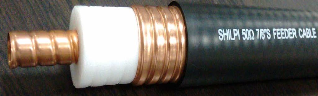
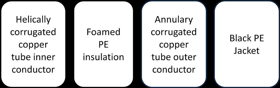
27 Inner Conductor The inner conductors of corrugated coaxial cables consist of copper wire, copper clad aluminium (CCA) wire or copper tube. For corrugated cables with small dimensions or braided cables, wires are used to guarantee sufficient flexibility. The inner conductors of corrugated coaxial cables with larger dimensions are made of copper tubes which ensures low weight as well as the necessary flexibility. Spiral (helical) corrugation of inner conductor tube lends the corrugated coaxial cable additional flexibility. 27 P age
28 Outer Conductor The outer conductor of corrugated coaxial cable is formed by a welded copper tube with either spiral/helical or circular/annular/ring-shaped corrugations. The welded copper tube guarantees RF shielding with screening attenuation values in excess of 120 db. Spiral corrugations, braids and foils are used for highly flexible cable versions. The deep and tightly spaced corrugations in the outer conductor of corrugated coaxial cables result in the smallest possible bending radii and highest flexibility. 28 P age
29 Dielectric In all coaxial cables, highly foamed polyethylene (FPE) ensures excellent attenuation to be achieved with the smallest possible dimensions. Foam coax will have 15% less attenuation than cables with solid PE dielectric. Also, FPE cables are low weight 65% less than solid PE cables(at the same attenuation) and smaller diameter 25% smaller than solid PE cables(at the same attenuation).foam coax can absorb moisture increasing loss. The insulation (dielectric) is used to provide separation between the conductors. The word electric derives from Greek elektron which translates to amber (An insulating material known to produce an electric charge when rubbed).the prefix di- infers the effect of preventing flow of electrons(current).a dielectric then is a barrier-an insulator-separating positive and negative electric charges from one another, preventing direct current flow. This action is typified by a capacitor. HDPE & LDPE are blended with a minimum amount of an endoderm nucleating agent to achieve required melt strength and viscosity for bubble growth and even cell distribution. For foaming of dielectric, preferably CO₂ is used as foaming gas due to its high solubility in polymer melts and its inertness. Foam rates up to 80% void ratio (expansion) with an uniform cell distribution providing highest quality signal transmission and minimum attenuation. It is desirable that the dielectric has stable electrical characteristics (dielectric constant & dissipation factor) across a broad frequency range. The most common materials used are polyethylene (PE), polypropylene (PP), fluorinated ethylene propylene (FEP) and poly tetra fluoro ethylene (PTFE).PE & PP are desirable in lower cost, power and temperature range applications. A thin layer of unfoamed polyethylene is applied directly to the inner conductor so that the dielectric can be stripped with ease. A physical foaming process produces up to 80% of the polyethylene with a fine pore, non-hygroscopic cell structure that lays the foundation for the cable s electrical performance. High foaming means a high proportion of air in the dielectric which results in lower weight, and attenuation characteristics approaching those of air dielectric cables of similar size. 29 P age
30 Jacket Options Black polyethylene is the standard outer jacket for all cables. This material is suitable for indoor and outdoor use (also underground). It is UV-resistant and halogen-free, and develops no corrosive gases in case of fire. For applications which demand flame-retardant cables an outer cable jacket made of FRNC material (Flame Retardant Non Corrosive) is available. The FRNCmaterial is also halogen-free and enables the cable to comply with the various listed IEC, NEC and UL flame tests. 30 P age
31 Tensile Strength The tensile strength of a cable defines the maximum permissible tensile force which may be applied to the cable during installation or handling. The unit of measurement is Newton (N) and takes into account all the materials used in the cable. In case of corrugated conductors, tensile strength is naturally less than in the case of smooth conductors. Exceeding the quoted values may result in impairment of the cable s mechanical or electrical characteristics. The values are determined by the technical measuring instruments and include an additional safety factor. The values are based on a maximum cable elongation by 0.2%. 31 P age
32 Bending Radius Specific minimal bending radii are defined for all types and cable sizes. A distinction is drawn between single bending and repeated bending. In case of single bending, the cable should not be bent back again after reaching its minimal bending radius, as this could result in damage to the cable. Repeated bending allows the cable to be bent to the minimal bending radius at least 15 times. It is typical for cable to be bent between 40 and 50 times without any impairment of its transmission characteristics. A cable s behavior and stability when subjected to repeated bending is very important during installation and assembly. Repeated bending also gives an indication of the minimum admissible reel core radius. Electrical and mechanical values of coaxial cables remain stable even after repeated bending. The minimum bending radii guarantee simple and reliable installation of the cables, resulting in dependable and endurable connections. Advantage of RF cables with corrugated conductors is their flexibility. 32 P age
33 Bending Moment A reference value for defining the ease at which a cable can be bent. A particular advantage of RF cables with corrugated conductors is their flexibility, as expressed in the bending moment. The cable under test is fixed in a straight support and a perpendicular force is introduced at a certain distance of 1 metre away from the support. The necessary force to deflect the cable by half this distance multiplied by the distance gives the bending moment. 33 P age
34 Flat Plate Crush Strength A reference value for defining the load required to create some amount of deformation to a cable s outer conductor applicable to applications where a cable is to be buried under earth or concrete. A particular advantage of the outer conductor corrugation is the fact that it gives the cable a very high crush resistance. If the given values are not exceeded the local impedance change is less than 0.5 Ω.For instance, In order to compress a 100 mm length section of Shilpi 7/8 S cable (SCR078SC) to reduce the impedance by 0.5Ω, It is necessary to apply a force of more than 1400 N (143 Kg). Unit of crush strength is N/mm cable length. 34 P age
35 Temperature Ranges Temperature ranges are defined for cables in storage, during installation and operation. Following table shows the temperature ranges which apply for cables with a standard polyethylene jacket or FRNC jacket : Polyethylene jacket FRNC jacket Storage : -70 C to +85 C -70 C to +85 C Installation : -40 C to +60 C -40 C to +60 C Operation : -55 C to +85 C -55 C to +85 C 35 P age
36 Recommended Hanger Spacing Various aspects need to be considered when fastening corrugated cables. Hangers must be spaced in accordance with specific values that are dependent on the location, the environmental conditions and the choice of installation materials. Extreme loads to the cable due to icing or strong winds must be taken into account when calculating the distance between the hangers. The recommended maximum hanger spacing for various cable sizes are shown in the below table: ¼ S 3/8 S ½ S ½ F 5/8 F 7/8 S 7/8 F 1-1/4 F 1-5/8 F 0.6 m 0.6 m 0.8 m 0.8 m 1.0 m 1.0 m 1.0 m 1.2 m 1.5 m Coaxial cables with corrugated outer Conductor 36 P age
 Manager, QA SHILPI CABLE TECHNOLOGIES")
, Rajasthan, India Mail to:")
37 Mithilesh K Singh, B.Tech. (ECE) Manager, QA SHILPI CABLE TECHNOLOGIES LIMITED SP-1037, RIICO Industrial Area, Chopanki Bhiwadi (Alwar), Rajasthan, India Mail to: mithilesh@shilpicabletech.com 37 P age
Connection technology for wireless communication systems
 Connection technology for wireless communication systems Rosenberger Rosenberger, founded in 1958, is a family owned company and ranks today among the top global manufacturers of high-frequency coaxial
S-Link. RF Cable Solution
 S-Link RF Cable Solution Netop supplys complete RF subsystem for site application with Rosenberger S-Link site solution package which include feeder cables, jumpers, connectors, surge arresters, grounding
EC 200 CHARACTERISTICS D A T A S H E E T. Kabelwerk EUPEN AG cable. M e c h a n i c a l c h a r a c t e r i s t i c s
 EC 200 EC200 - Rev. 3-23.06.11 Characteristic impedance 50 ± 2 Material copper wire Nominal capacity (pf/m) 80.5 Construction - Relative propagation velocity (%) 83 Diameter (mm) 1.05 Inductance (µh/m)
Edition January 2008
 Edition January 2008 New eupen corrugated aluminium cables INTRODUCTION EUPEN extends its cable product range with two specifically designed foam dielectric corrugated aluminum cables EA5-50 7/8 and EA7-50
EXCELLENT ELECTRICAL PERFORMANCES
 50OHMS CORRUGATED COPPER TUBE COAXIAL CABLE PRODUCT INTRODUCTION 2 Hansen's manufacturing of wide-scope 50ohms corrugated copper coaxial Cable is the fruitful result of the engineers' diligent research
Site Solutions Coaxial Feeder Cables 50 Ω High Performance Transmission Line Solutions
 Site Solutions Coaxial Feeder Cables 50 Ω High Performance Transmission Line Solutions Intro Rosenberger Group Rosenberger is one of the worldwide leading suppliers of controlled impedance and optical
SBCA Industry Standards Subcommittee. Specification for 75 Ω Flexible RF Coaxial Drop Cable for Direct Broadcast Satellite (DBS) Installations
 Installations") SBCA Industry Standards Subcommittee Document: SBCA Series 6 Recommended Practices Date of Issue: Specification for 75 Ω Flexible RF Coaxial Drop Cable for Direct Broadcast Satellite (DBS) Installations
SBCA Industry Standards Subcommittee Document: SBCA Series 6 Recommended Practices Date of Issue: Specification for 75 Ω Flexible RF Coaxial Drop Cable for Direct Broadcast Satellite (DBS) Installations
MIL-C-17 Standard RF Coaxial Cable Low Loss & Ultra Low Loss RF Microwave Cable ANTENNA & TEST Cable up to 26.5 GHz
 MIL-C-17 Standard RF Coaxial Cable Low Loss & Ultra Low Loss RF Microwave Cable ANTENNA & TEST Cable up to 26.5 GHz Low Loss Low Density PTFE Dielectric RF Microwave Coaxial Cable Silver Plated Copper
Chapter 12: Transmission Lines. EET-223: RF Communication Circuits Walter Lara
 Chapter 12: Transmission Lines EET-223: RF Communication Circuits Walter Lara Introduction A transmission line can be defined as the conductive connections between system elements that carry signal power.
ENGINEERING COMMITTEE Interface Practices Subcommittee AMERICAN NATIONAL STANDARD ANSI/SCTE
 ENGINEERING COMMITTEE Interface Practices Subcommittee AMERICAN NATIONAL STANDARD ANSI/SCTE 177 2012 Specification for Braided 75 Ω, Mini-Series Quad Shield Coaxial Cable for CMTS and SDI cables NOTICE
TERM PAPER OF ELECTROMAGNETIC
 TERM PAPER OF ELECTROMAGNETIC COMMUNICATION SYSTEMS TOPIC: LOSSES IN TRANSMISSION LINES ABSTRACT: - The transmission lines are considered to be impedance matching circuits designed to deliver rf power
LMR LMR Ohm Flexible Low Loss Coaxial Cable TIMES MICROWAVE SYSTEMS
 LMR-200-75 LMR -200-75 Ohm Flexible Low Loss Coaxial Cable Ideal for Satellite Applications Video Applications-CCTV, CATV, baseband or broadband In-Building Feeder Runs Any 75 ohm Wireless Application
AVA5-50FX. Product Classification. Standards And Qualifications. Construction Materials. Dimensions. Electrical Specifications
 AVA5RK-50FX, HELIAX Andrew Virtual Air Coaxial Cable, corrugated copper, 7/8 in, black, Non-halogenated, fire retardant polyolefin jacket B2ca-s1b,d1 Product Classification Brand Product Series Product
C240-NFSM-3M. Jumper Assembly Sample Label. Product Classification. General Specifications. Return Loss/VSWR
 C240-NFSM-3M Product Classification Brand Product Series Product Type CNT Jumper with interface types N Female and SMA Male, 3m CNT Braided cable assembly General Specifications Body Style, Connector A
Jumper cable. Feeder cable + connector. Cable clamp. Grounding kit
 Mobile Networks 1 Jumper cable Feeder cable + connector Cable clamp Grounding kit 2 28 Superflexible and Extraflexible Cables Draka superflexible RFF cables and extraflexible RFE cables offer the most
COAX 101. Author: Rob Wessels. Vice President of Engineering
 COAX 101 Author: Rob Wessels Vice President of Engineering Structured cable systems have very thorough standards for fiber optic and twisted pair installations. The cabling components and installed systems
Speedflex. Halogen free coaxial cables.
 Speedflex Halogen free coaxial cables Speedflex is a completely halogen-free and environmentally-friendly alternative to standard RG coaxial cables. Speedflex Item Material Speedflex Speedflex Speedflex
C400-UMUM-100. Jumper Assembly Sample Label. Product Classification. General Specifications. Return Loss/VSWR
 C400-UMUM-100 Product Classification Brand Product Series Product Type CNT Jumper with interface types UHF Male and UHF Male, 30.48 m CNT Braided cable assembly General Specifications Body Style, Connector
SMB Plug Connector Crimp/Solder Attachment for RG174, RG316, RG188, LMR-100, PE-B100, PE-C100, inch
 SMB Plug Connector Crimp/Solder Attachment for RG174, RG316, RG188, LMR-100, PE-B100, PE-C100, 0100 inch RF Connectors Technical Data Sheet PE4046 Configuration SMB Plug Connector MIL-STD-348A 50 Ohms
ZHONGTIAN TECHNOLOGIES CO., LTD
 ZHONGTIAN TECHNOLOGIES CO., LTD Contents Company profile...1 Quality certificates.. 2 Manufacture equipment 3 Products profile. 4 Radio Coaxial Cables 5 HHTAY-50-42 (1-5/8 ) HCTAY-50-32 (1-1/4 ) HCTAY-50-22
C400-TMTM-30-X. Jumper Assembly Sample Label. Product Classification. General Specifications. Electrical Specifications
 C400-TMTM-30-X Product Classification Brand Product Series Product Type CNT-400-FR CNT Jumper with interface types TNC Male and TNC Male, 9.14 m CNT CNT-400 Braided cable assembly General Specifications
SMA Male Connector Crimp/Solder Attachment for RG174, RG316, RG188 Gold Plated
 SMA Male Connector Crimp/Solder Attachment for RG174, RG316, RG188 Gold Plated RF Connectors Technical Data Sheet PE45145 Configuration SMA Male Connector 50 Ohms Straight Body Geometry RG174, RG316, RG188
Computer Networks Lecture -4- Transmission Media. Dr. Methaq Talib
 Computer Networks Lecture -4- Transmission Media Dr. Methaq Talib Transmission Media A transmission medium can be broadly defined as anything that can carry information from a source to a destination.
C195-SMQM-3M. Jumper Assembly Sample Label. Product Classification. General Specifications. Return Loss/VSWR
 C195-SMQM-3M Product Classification Brand Product Series Product Type CNT-195 CNT Jumper with interface types SMA Male and QMA Male, 3M CNT CNT-195 Braided cable assembly General Specifications Body Style,
TNC Male Right Angle Connector Crimp/ Solder Attachment for RG174, RG316, RG188, inch, PE-B100, PE-C100, LMR-100
 TNC Male Right Angle Connector Crimp/ Solder Attachment for RG174, RG316, RG188, 0100 inch, PE-B100, PE-C100, LMR-100 RF Connectors Technical Data Sheet PE4455 Configuration TNC Male Connector 50 Ohms
RADIALL DETAIL SPECIFICATION FOR SHF COAXIAL CABLE
 1/18 RADIALL DETAIL SPECIFICATION FOR SHF COAXIAL CABLE Rédigé par / Written by Responsabilité / Responsibility Date Signature S. POIZAT Space Project Manager 31/08/2016 Vérifié par / Verified by V.EUDELINE
ATBTK-MF-4G. Product Classification. Mechanical Specifications. Dimensions. Regulatory Compliance/Certifications.
 ATBTK-MF-4G Bias Tee Kit, AISG Compatible 698-2700 MHz Product Classification Product Type RET bias tee Mechanical Specifications Antenna Interface 7-16 DIN Female BTS Interface 7-16 DIN Male Dimensions
LTE high-performance coaxial cables (RG replacement)
") LTE high-performance coaxial cables (RG replacement) Center Conductor: See table below. Dielectric: LTE (extruded low-density PTFE) or low density / composite. Inner Shield: 875-892: None. 900-142: Flat
LTE high-performance coaxial cables (RG replacement) Center Conductor: See table below. Dielectric: LTE (extruded low-density PTFE) or low density / composite. Inner Shield: 875-892: None. 900-142: Flat
RF Connectors Technical Data Sheet. Description Minimum Typical Maximum Units. Frequency Range DC 3 GHz VSWR 1.25:1 Operating Voltage (AC) 335 Vrms.
 335 Vrms.") BNC Male Connector Crimp/Crimp Attachment for 100 inch, RG316, RG174, RG188, LMR-100, LMR- 100, LMR-100-FR, PE-C100, PE-B100 RF Connectors Technical Data Sheet PE45045 Configuration BNC Male Connector
BNC Male Connector Crimp/Crimp Attachment for 100 inch, RG316, RG174, RG188, LMR-100, LMR- 100, LMR-100-FR, PE-C100, PE-B100 RF Connectors Technical Data Sheet PE45045 Configuration BNC Male Connector
C400-NMTM-1M. Jumper Assembly Sample Label. Product Classification. General Specifications. Return Loss/VSWR
 C400-NMTM-1M Product Classification Brand Product Series Product Type CNT-400 CNT Jumper with interface types N Male and TNC Male, 1m CNT CNT-400 Braided cable assembly General Specifications Body Style,
EZ-200-NMH-D ok by tech Svcs
 EZ-200-NMH-D ok by tech Svcs EZ-200-NMH-D ok by tech Svcs LMR LMR-200 600 TIMES MICROWAVE SYSTEMS LMR -200 Flexible Low Loss Communications Coax Ideal for Jumper Assemblies in Wireless Communications Systems
Tru products are now under the Tru-Win brand from Winchester Interconnect.
 TRUflex PWR Series TRUflex PWR Series cable assemblies offers an extensive line of flexible RF cable assembly and connector solutions for applications that require RF high power/voltage capability as well
N Male Connector Clamp/Solder Attachment for PE-C500, LMR-500
 N Male Connector Clamp/Solder Attachment for PE-C500, LMR-500 RF Connectors Technical Data Sheet PE44046 Configuration N Male Connector MIL-STD-348A 50 Ohms Features Gold Plated Brass Contact Applications
REQUEST FOR INFORMATION (RFI) RFI NO: /WJG
 RFI NO: /WJG") (RFI) RFI NO: 15-219/WJG WASHINGTON METROPOLITAN AREA TRANSIT AUTHORITY 600 FIFTH STREET, NW WASHINGTON DC 20001 ( WMATA OR AUTHORITY ) 1 ⅝ INCH RADIATING COAXIAL CABLE DATE: AUGUST 7, 2015 Contents Introduction...
(RFI) RFI NO: 15-219/WJG WASHINGTON METROPOLITAN AREA TRANSIT AUTHORITY 600 FIFTH STREET, NW WASHINGTON DC 20001 ( WMATA OR AUTHORITY ) 1 ⅝ INCH RADIATING COAXIAL CABLE DATE: AUGUST 7, 2015 Contents Introduction...
ZHONGTIAN TECHNOLOGIES CO., LTD
 ZHONGTIAN TECHNOLOGIES CO., LTD Contents Company profile...1 Quality certificates.. 2 Manufacture equipment 3 Products profile. 4 Radio Frequency Coaxial Cables 5 HHTAY-50-42 (1-5/8 ) HCTAY-50-32 (1-1/4
Since 1993 the company is ISO 9001 certified for all its products.
 Edition 01 / 2012 The foundation of the cable factory KABELWERK EUPEN AG as manufacturer of electrical cables goes back to the beginning of the 20th century. Today the company has a staff of 950 people
Detailed Specifications & Technical Data
 Description: Series 11, 14 AWG solid.064" bare copper-covered steel conductor, gas-injected foam polyethylene insulation, Duobond IV quad shield (60% and 40% coverage), PVC jacket Physical Characteristics
N Male Right Angle Connector Clamp/Solder Attachment For 1/2 inch Annular, 1/2 inch Flexible, PE-1/2FAC. Cable Attachment Method (Shield/Contact)
") N Male Right Angle Connector Clamp/Solder Attachment For 1/2 inch Annular, 1/2 inch Flexible, PE-1/2FAC TECHNICAL DATA SHEET N Male Right Angle Connector Clamp/Solder Attachment For 1/2 inch Annular, 1/2
N Male Right Angle Connector Clamp/Solder Attachment For 1/2 inch Annular, 1/2 inch Flexible, PE-1/2FAC TECHNICAL DATA SHEET N Male Right Angle Connector Clamp/Solder Attachment For 1/2 inch Annular, 1/2
Analysis and Study the Performance of Coaxial Cable Passed On Different Dielectrics
 Analysis and Study the Performance of Coaxial Cable Passed On Different Dielectrics Baydaa Hadi Saoudi Nursing Department, Technical Institute of Samawa, Iraq. Email:baydaa_s2007@yahoo.com Abstract In
RP TNC Male Connector Crimp/Solder Attachment for PE-C240, RG8X, inch, LMR-240, LMR-240-DB, LMR-240-UF, B7808A
 RP TNC Male Connector Crimp/Solder Attachment for PE-C240, RG8X, 0240 inch, LMR-240, LMR-240-DB, LMR-240-UF, B7808A RF Connectors Technical Data Sheet PE44670 Configuration TNC Male Reverse Polarity Connector
H155A02. Product Description. Product Specifications. Technical Specifications. Application. Bend Radius. CCB-Sub-Crush Resistance.
 H155A02 Part Number: H155A02 COAX RF H155 FRNC Product Description COAX RF H155 FRNC Product Specifications Application Application 1: Application 2: 50 Ohm low loss coaxial transmission cable designed
Coaxial Cables Coax Serie. HF Steckverbinder für Mobilfunk-Anwendungen. in Bulk Rings or on Cable Drums
 4.3-10 Coax Serie Coaxial Cables HF Steckverbinder für Mobilfunk-Anwendungen in Bulk Rings or on Cable Drums Coaxial Cables In addition to the wide range of coaxial connectors, Telegärtner offers suitable
LMR-240. LMR -240 Flexible Low Loss Communications Coax TIMES MICROWAVE SYSTEMS
 LMR-240 LMR -240 Flexible Low Loss Communications Coax Ideal for Jumper Assemblies in Wireless Communications Systems Short Antenna Feeder runs (e.g. WLL, GPS, LMR, Mobile Antennas) Any application (e.g.
Surge Protection and Grounding Issues
 Surge Protection and Grounding Issues Presented to SCTE Chicago Chapter January 21, 2004 By: Nisar Chaudhry VP Electrical Engineering, CTO Introduction Transients caused by disturbances on the power lines
FBT-195 TIMES MICROWAVE SYSTEMS
 FBT-195 Engineered Products: FBT TM -195 Flexible Low Loss High Power Communications Coax Ideal for High Power Base Station Jumper Assemblies In-Building Plenum Feeder Runs Any High Power Low Loss RF cable
Labs. Introduction. Specialty Family
 INC. Labs Introduction Specialty Family Features K-Jumper: Affordable, High Performance Interconnect up to 35 GHz Space-Flex : Semi-Rigid and Flexible Cable Assemblies for S-Level Space T-Flex : Flexible
Amateur Extra Manual Chapter 9.4 Transmission Lines
 9.4 TRANSMISSION LINES (page 9-31) WAVELENGTH IN A FEED LINE (page 9-31) VELOCITY OF PROPAGATION (page 9-32) Speed of Wave in a Transmission Line VF = Velocity Factor = Speed of Light in a Vacuum Question
Telegärtner Mobile Radio Base Station Components.
 Telegärtner Mobile Radio Base Station Components www.telegaertner.com Mobile Radio Base Station Components Components: Connectors EMP Protectors Jumper Cables Adaptors Tools and Accessories 2011 Telegärtner
2. The Basic principle of optical fibre (Or) Working principle of optical fibre (or) Total internal reflection
 Working principle of optical fibre (or) Total internal reflection") Introduction Fibre optics deals with the light propagation through thin glass fibres. Fibre optics plays an important role in the field of communication to transmit voice, television and digital data signals
Introduction Fibre optics deals with the light propagation through thin glass fibres. Fibre optics plays an important role in the field of communication to transmit voice, television and digital data signals
DETAIL SPECIFICATION SHEET CABLES, RADIO FREQUENCY, SEMIRIGID, COAXIAL, SEMI-AIR-DIELECTRIC,.875 TO INCHES OUTSIDE DIAMETER, 50 OHMS
 INCH-POUND MIL-DTL-22931/11B 21 August 2013 SUPERSEDING MIL-C-22931/11A 20 January 1972 DETAIL SPECIFICATION SHEET CABLES, RADIO FREQUENCY, SEMIRIGID, COAXIAL, SEMI-AIR-DIELECTRIC,.875 TO 1.005 INCHES
Microwave Coax. w w w. t e m p f l e x. c o m ( ) M i l f o r d R d. S o u t h G r a f t o n, M A
 M i l f o r d R d. S o u t h G r a f t o n, M A") Microwave Coax w w w. t e m p f l e x. c o m ( 5 0 8 ) 8 3 9-5 9 8 7 2 6 M i l f o r d R d. S o u t h G r a f t o n, M A 0 1 5 6 0 Microwave Coax Product Description Low Loss, Flexible Microwave products
Microwave Coax w w w. t e m p f l e x. c o m ( 5 0 8 ) 8 3 9-5 9 8 7 2 6 M i l f o r d R d. S o u t h G r a f t o n, M A 0 1 5 6 0 Microwave Coax Product Description Low Loss, Flexible Microwave products
QN Male Connector Crimp/Solder Attachment for RG55, RG141, RG142, RG223, RG400
 QN Male Connector Crimp/Solder Attachment for RG55, RG141, RG142, RG223, RG400 RF Connectors Technical Data Sheet PE44978 Configuration QN Male Connector 50 Ohms Straight Body Geometry Features Max Operating
Partnering ideas with technology THEORY AND APPLICATION
 www.bhccable.com sales@bhccable.com 1-877-755-5242 Partnering ideas with technology Coaxial Cable Transmission of electrical signals over wire lines requires the use of two conductors to complete the circuit.
Telecommunication Wiring Questions
 Telecommunication Wiring Questions 1. is the process of modifying a carrier frequency in rhythm to the audio frequency. A, Modulation B. Amplitude C. Change of phase D. Interference 2. is the property
Harbour Industries Coaxial Cable Catalog
 Low Loss Light Weight Strip Braid Harbour Industries Coaxial Cable Catalog Low Loss Light Weight Strip Braid MIL-C-17 Spiral Strip High Strength COAXIAL CABLES LL (Low Loss) Cables... page 4-7 Expanded
K20 & L120 LSZH Armoured F/FTP Cat6 Cables
 K20 & L120 LSZH Armoured F/FTP Cat6 Cables The cables are designed for high speed data transmissions, and are suitable for installations in cable trays or on hooks. RATP CAT6-K20 (for K20 cable) FRANCE
EC Transmission Lines And Waveguides
 EC6503 - Transmission Lines And Waveguides UNIT I - TRANSMISSION LINE THEORY A line of cascaded T sections & Transmission lines - General Solution, Physical Significance of the Equations 1. Define Characteristic
ECOFLEX 10 Characteristics Diameter 10,2 mm. ECOFLEX 15 Characteristics Diameter 14,6 mm. AIRCOM PLUS Characteristics Diameter 10,3 mm
 AIRCOM PLUS Characteristics Diameter 10,3 mm Attenuation @ 1 GHz/100m 13,4 db Attenuation @ 1 GHz/100ft 4,08 db 10 GHz ECOFLEX 10 Characteristics Diameter 10,2 mm Attenuation @ 1 GHz/100m 14,2 db Attenuation
1/2", Corrugated, Jacketed UL-910, CATVP AP012J Physical Dimensions Center Conductor
 AirCell PLENUM CABLES 50 Ohm Plenum, 1/2" Description Product Number Frequency MHz Attenuation and Coupling Loss 1/2", Corrugated, Jacketed UL-910, CATVP AP012J50 5 0.159 0.56 17.6 10 0.225 0.82 12.0 20
The below identified patent application is available for licensing. Requests for information should be addressed to:
 DEPARTMENT OF THE NAVY OFFICE OF COUNSEL NAVAL UNDERSEA WARFARE CENTER DIVISION 1176 HOWELL STREET NEWPORT Rl 02841-1708 IN REPLY REFER TO Attorney Docket No. 300104 25 May 2017 The below identified patent
TECHNICAL INFORMATION
 TECHNICAL INFORMATION TECHNOLOGY Y-Junction circulator PORT 1 PORT 2 PORT 3 FIG. 1 The Y-junction circulator uses spinel ferrites or garnet ferrites in the presence of a magnetic bias field, to provide
EC6011-ELECTROMAGNETICINTERFERENCEANDCOMPATIBILITY
 EC6011-ELECTROMAGNETICINTERFERENCEANDCOMPATIBILITY UNIT-3 Part A 1. What is an opto-isolator? [N/D-16] An optoisolator (also known as optical coupler,optocoupler and opto-isolator) is a semiconductor device
PhaseTrack. Phase Stable Cable Assemblies
 PhaseTrack Phase Stable Cable Assemblies Phased Array Systems All Phase Sensitive Systems All Phase Sensitive Platforms All System Platforms (Ground, Sea, Airborne, Space) INTRODUCTION Phase stable interconnects
MICROWAVE & RF CABLE Semi-Rigid, hand-formable & flexible microwave cable
 MICROWAVE & RF CABLE Semi-Rigid, hand-formable & flexible microwave cable TABLE OF CONTENTS The Story of Micro-Coax...2-3 Microwave Cable Selection Guide...4-5 Semi-Rigid Coaxial Cable...5 UTiFORM Tin-Dipped
TIMES QUALIFIED MILTECH CABLE ASSEMBLIES
 TIMES QUALIFIED MILTECH CABLE ASSEMBLIES Starting on page 5 MILTECH Qualified Cable Assemblies Manufactured to the requirements of MIL-C-87104 and MIL-T-81490, FAA FAR25 and DO-160 Fully vapor sealed for
Generation of Sub-nanosecond Pulses
 Chapter - 6 Generation of Sub-nanosecond Pulses 6.1 Introduction principle of peaking circuit In certain applications like high power microwaves (HPM), pulsed laser drivers, etc., very fast rise times
Cable Type 100. CAI Certification Specification
 Cable Type 100 CAI Certification Specification Ref: CAI-007-C / 100 / 12-2016 Confederation of Aerial Industries Ltd Communications House 41a Market Street WATFORD Herts WD18 0PN Tel: 01923 803030 Fax:
Module 2. Studoob.in - Where Learning is Entertainment
 Module 2 Module 2 Transmission media - Guided Transmission Media: Twisted pair, Coaxial cable, optical fiber, Wireless Transmission, Terrestrial microwave, Satellite microwave. Wireless Propagation: Ground
Exercise 3-2. Effects of Attenuation on the VSWR EXERCISE OBJECTIVES
 Exercise 3-2 Effects of Attenuation on the VSWR EXERCISE OBJECTIVES Upon completion of this exercise, you will know what the attenuation constant is and how to measure it. You will be able to define important
CIRCULATOR APPLICATION NOTE ANV001.
 APPLICATION NOTE ANV001 Bötelkamp 31, D-22529 Hamburg, GERMANY Phone: +49-40 547 544 60 Fax: +49-40 547 544 666 Email: info@valvo.com A Circulator is defined as a non-reciprocal, passive three ports, ferromagnetic
CUSTOM DESIGN COAXIAL CABLES BY SICAB
 CUSTOM DESIGN COAXIAL CABLES BY SICAB. COAX RG 58 C/U Application: Coaxial Cable 50 Ohm For indoor installation as well as in industrial areas in conduits and cable ducts, for transmission of high frequency
U.S. Toll Free (800) Phone (802) Canada Phone (450)
 Phone (802) Canada Phone (450)") Harbour Industries LLC is the preeminent manufacturer of high temperature and high performance coaxial cables for the military, aerospace, commercial, and industrial markets. Design and process engineering
Harbour Industries LLC is the preeminent manufacturer of high temperature and high performance coaxial cables for the military, aerospace, commercial, and industrial markets. Design and process engineering
Cable Type 125. CAI Certification Specification
 Cable Type 125 CAI Certification Specification Ref: CAI-008-C / 125 / 12-2016 Confederation of Aerial Industries Ltd Communications House 41a Market Street WATFORD Herts WD18 0PN Tel: 01923 803030 Fax:
Tru products are now under the Tru-Win brand from Winchester Interconnect.
 TRU MEIA Series Tru-Win MEIA offers the latest innovation in high power connector design. The MEIA interface provides equivalent kw power handling compared to similar EIA connector line sizes but provides
Tailored Insulations for High Transmission Rate Data Cable
 Tailored Insulations for High Transmission Rate Data Cable Ann Watson William Fajardo Ann Watson Borealis Polymers, Belgium William Fajardo Borealis Compounds Inc, ABSTRACT Even with the spread of fibre
Figure 4-1. Figure 4-2 Classes of Transmission Media
 Electromagnetic Spectrum Chapter 4 Transmission Media Computers and other telecommunication devices transmit signals in the form of electromagnetic energy, which can be in the form of electrical current,
EACON. Field mountable microwave cable. INEXIM Sp. z o.o. Edition Bezpośredni importer i dystrybutor
 EACON Field mountable microwave cable Edition 2012 Bezpośredni importer i dystrybutor INEXIM Sp. z o.o. www.inexim.pl Easy connected EACON - the field mountable cable assembly 4 EACON 4C 6 Suitable to
Design and Construction of a150kv/300a/1µs Blumlein Pulser
 Design and Construction of a150kv/300a/1µs Blumlein Pulser J.O. ROSSI, M. UEDA and J.J. BARROSO Associated Plasma Laboratory National Institute for Space Research Av. dos Astronautas 1758, São José dos
Practical Antennas and. Tuesday, March 4, 14
 Practical Antennas and Transmission Lines Goals Antennas are the interface between guided waves (from a cable) and unguided waves (in space). To understand the various properties of antennas, so as to
ACR (Attenuation to Crosstalk Ratio) ACR-F. Alien Crosstalk. Attenuation (signal attenuation, conductor attenuation)
 ACR-F. Alien Crosstalk. Attenuation (signal attenuation, conductor attenuation)") ACR (Attenuation to Crosstalk Ratio) The distance between the wanted signal and the interfering signal (ACR) is an important factor for the transmission quality. To ensure a faultless transmission, the
ACR (Attenuation to Crosstalk Ratio) The distance between the wanted signal and the interfering signal (ACR) is an important factor for the transmission quality. To ensure a faultless transmission, the
The shunt capacitor is the critical element
 Accurate Feedthrough Capacitor Measurements at High Frequencies Critical for Component Evaluation and High Current Design A shielded measurement chamber allows accurate assessment and modeling of low pass
N Male Connector Crimp/Solder Attachment For RG58
 N Male Connector Crimp/Solder Attachment For RG58 RF Connectors Technical Data Sheet PE4329 Configuration N Male Connector 50 Ohms Straight Body Geometry RG58 Interface Type Crimp/Solder Attachment Electrical
Microwave Coax Cable
 Cable LINCOS microwave coaxial cable basic construction is shown below : Ø 1. Inner Conductor : Solid or Strand Sliver Plated Copper Ø 2. Insulation : Wrapped Low Density PTFE Ø 3. Outer Conductor : Sliver
Coax element HF75-0,3/1,6 RG179 HF50-0,9/2,95 RG58 HF50-0,3/0,84 RG178 Part. No. CFKoax1 CFKoax2 CFKoax3
 Overview Coax element HF75-0,3/1,6 RG179 HF50-0,9/2,95 RG58 HF50-0,3/0,84 RG178 Part. No. CFKoax1 CFKoax2 CFKoax3 Example drawing (see the chapter belonging to the cable for details) (see the chapter belonging
TwenCombi Cat-5E FTP(3x) - Coax 9 - EIBA - tube PE 5 mm
 - Coax 9 - EIBA - tube PE 5 mm") name: TKF article number: 10305 description Nr.: POE- PS- 10305 PT F F F 800 B C 1 2 3 4 5 6 7 Assembly: 1. Primary tube 5 mm 2. CAT 5 E FTP cable 3. CAT 5 E FTP cable 4. Bus cable 5. Coax 9 cable 6. Separation
name: TKF article number: 10305 description Nr.: POE- PS- 10305 PT F F F 800 B C 1 2 3 4 5 6 7 Assembly: 1. Primary tube 5 mm 2. CAT 5 E FTP cable 3. CAT 5 E FTP cable 4. Bus cable 5. Coax 9 cable 6. Separation
5. EPC (Eupen Passive Components) Dummy Loads DC Isolators Splitters Packing Information
 Dummy Loads DC Isolators Splitters Packing Information") Edition 01 / 2014 2 www.eupen.com 1. Introduction 100 Years of Experience............................. 6 Over the World........................................... 8 2. Introduction to Eupen Radiating Cables
Edition 01 / 2014 2 www.eupen.com 1. Introduction 100 Years of Experience............................. 6 Over the World........................................... 8 2. Introduction to Eupen Radiating Cables
Technician License. Course
 Technician License Course Technician License Course Chapter 4 Lesson Plan Module - 9 Antenna Fundamentals Feed Lines & SWR The Antenna System The Antenna System Antenna: Transforms current into radio waves
The Principle V(SWR) The Result. Mirror, Mirror, Darkly, Darkly
 The Result. Mirror, Mirror, Darkly, Darkly") The Principle V(SWR) The Result Mirror, Mirror, Darkly, Darkly 1 Question time!! What do you think VSWR (SWR) mean to you? What does one mean by a transmission line? Coaxial line Waveguide Water pipe Tunnel
The Principle V(SWR) The Result Mirror, Mirror, Darkly, Darkly 1 Question time!! What do you think VSWR (SWR) mean to you? What does one mean by a transmission line? Coaxial line Waveguide Water pipe Tunnel
NETWORK CONNECTIVITY SYSTEMS
 NETWORK CONNECTIVITY SYSTEMS Installation Cable KS-STP Category 7 Installation Cable Certificates 10GBaseT FTP Category 6 Installation Cable UTP Category 6 Installation Cable UTP Category 5E Installation
Low Loss Pre-Connectorized Cable Sets, LL58 Series, DC-3.5GHz
 Low Loss Pre-Connectorized Cable Sets, LL58 Series, DC-3.5 reliable performance, dependable service Replace traditional RG types for benefit of: lower loss better shielding > - 90dB Drop in replacement
7/16 DIN Male Connector Clamp/Solder Attachment for RG213, RG55, RG141, RG142, RG223, RG400, RG303, PE-C195, PE-P195, LMR-195
 7/16 DIN Male Connector Clamp/Solder Attachment for RG213, RG55, RG141, RG142, RG223, RG400, RG303, PE-C195, PE-P195, LMR-195 RF Connectors Technical Data Sheet PE4567 Configuration 7/16 DIN Male Connector
Cable Attachment Method (Shield/Contact) Size Length, in [mm] 0.98 [24.89] Width/Dia., in [mm] [9.53]. Weight, lbs [g] 0.02 [9.07] 3.
![Cable Attachment Method (Shield/Contact) Size Length, in [mm] 0.98 [24.89] Width/Dia., in [mm] [9.53]. Weight, lbs [g] 0.02 [9.07] 3.](/thumbs/94/121044667.jpg "Cable Attachment Method (Shield/Contact) Size Length, in [mm] 0.98 [24.89] Width/Dia., in [mm] [9.53]. Weight, lbs [g] 0.02 [9.07] 3.") Configuration Interface Type Cable Attachment Method (Shield/Contact) Body Style PE-SR402AL,PE-SR402FL,RG402 Clamp/Solder Straight Electrical Specifications Impedance, Ohms 50 Mechanical Specifications
Configuration Interface Type Cable Attachment Method (Shield/Contact) Body Style PE-SR402AL,PE-SR402FL,RG402 Clamp/Solder Straight Electrical Specifications Impedance, Ohms 50 Mechanical Specifications
Bill Ham Martin Ogbuokiri. This clause specifies the electrical performance requirements for shielded and unshielded cables.
 098-219r2 Prepared by: Ed Armstrong Zane Daggett Bill Ham Martin Ogbuokiri Date: 07-24-98 Revised: 09-29-98 Revised again: 10-14-98 Revised again: 12-2-98 Revised again: 01-18-99 1. REQUIREMENTS FOR SPI-3
New LOW LOSS A Version
 Including the New LOW LOSS A Version Edition 02-2010 The foundation of the cable factory KABELWERK EUPEN AG as manufacturer of electrical cables goes back to the beginning of the 20th century. Today the
Use and abuse of screened cables
 December 2016 Use and abuse of screened cables Tim Williams Elmac Services 1 of 21 Outline How does a screened cable work? electric fields, magnetic fields, low versus high frequency Types of screen Transfer
Test Cable Assemblies
 Test Cable Assemblies DC-65 GHz 8851 SW Old Kansas Ave. Stuart, FL 34997 USA +1-772-286-9300 +1-800-544-5594 sales@emc-rflabs.com www.emc-rflabs.com Premium Test Cable Lab-Flex 200 Frequency to 31 GHz
Screening Attenuation When enough is enough
 Screening Attenuation When enough is enough Anders Møller-Larsen, Ph.D. M.Sc. E.E. Product Manager, Coax Network Introduction This white paper describes the requirements to screening attenuation of cables
Signal and Noise Measurement Techniques Using Magnetic Field Probes
 Signal and Noise Measurement Techniques Using Magnetic Field Probes Abstract: Magnetic loops have long been used by EMC personnel to sniff out sources of emissions in circuits and equipment. Additional
SMA Male QD Connector Crimp/Solder Attachment For RG142, RG223, RG400, RG55
 SMA Male QD Connector Crimp/Solder Attachment For RG142, RG223, RG400, RG55 RF Connectors Technical Data Sheet Configuration SMA Male Connector 50 Ohms Straight Body Geometry RG142, RG223, RG400, RG55
SPORTCRAFT ANTENNAS. INSTALLATION INSTRUCTIONS for FLUSH WINGTIP COM ANTENNAS
 01A SPORTCRAFT ANTENNAS INSTALLATION INSTRUCTIONS for FLUSH WINGTIP COM ANTENNAS 1.0 INTRODUCTION. 1.1 GENERAL. These antennas have been designed by Bob Archer of Torrance, California utilizing concepts